
AAS01 - Support pour écran plat ASUS - Free user manual and instructions
Find the device manual for free AAS01 ASUS in PDF.


| Product Type | Monitor Arm / Mount |
| Brand | ASUS |
| Model | AAS01 |
| Recommended Display Size | Up to 34 inches |
| Weight Capacity (Flat Display) | 3 - 11.5 kg (6.6 - 25.3 lbs) |
| Weight Capacity (Curved Display) | 3 - 8.5 kg (6.6 - 18.7 lbs) |
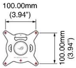
| VESA Mounting Pattern | 100 x 100 mm (3.94 x 3.94 in) |
| Desk Clamp Range | 10 - 80 mm (0.39 - 3.15 in) |
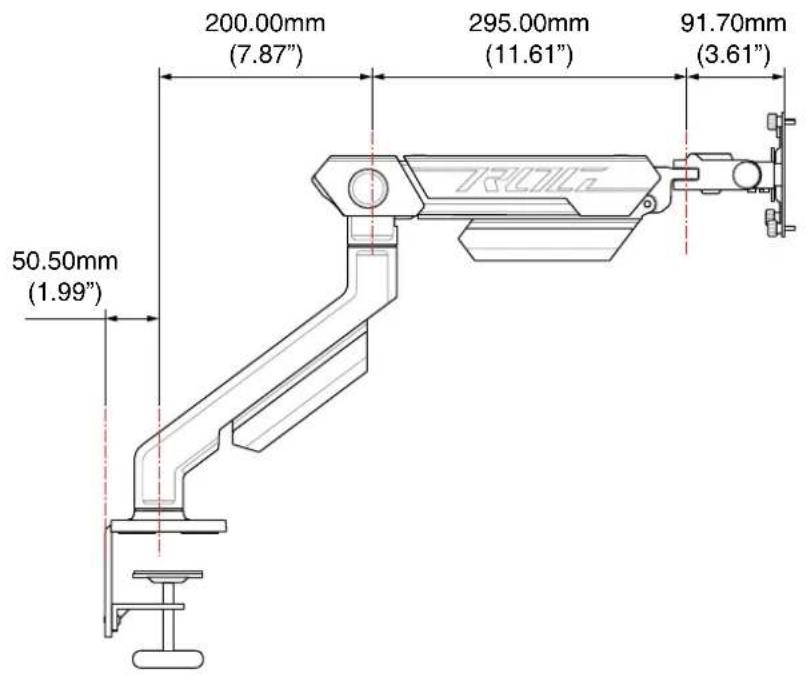
| Maximum Extension | 63.72 cm (25.08 in) |
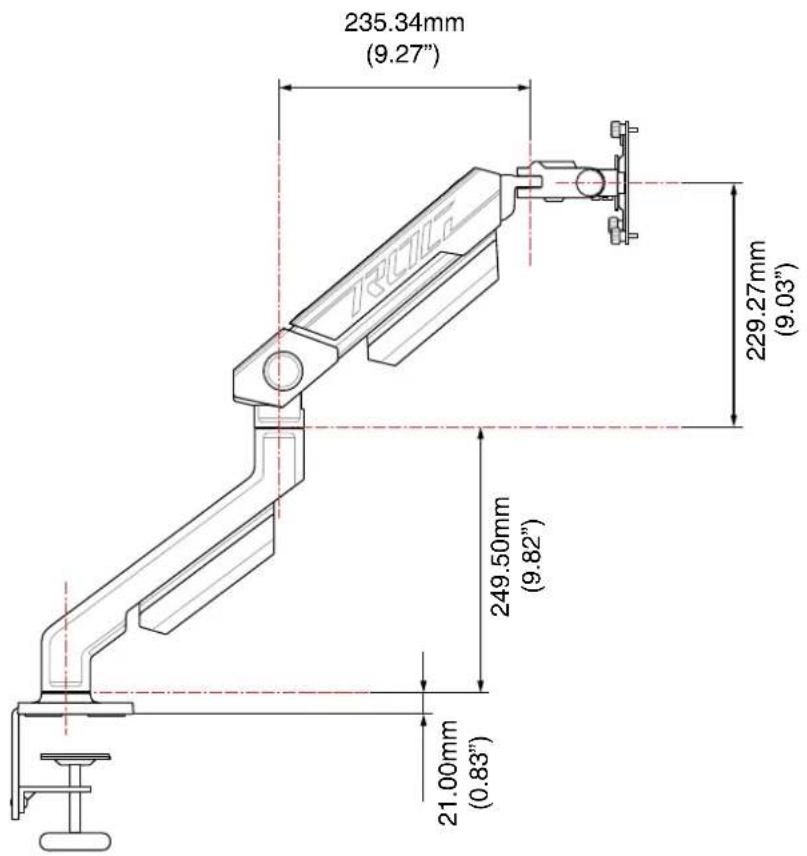
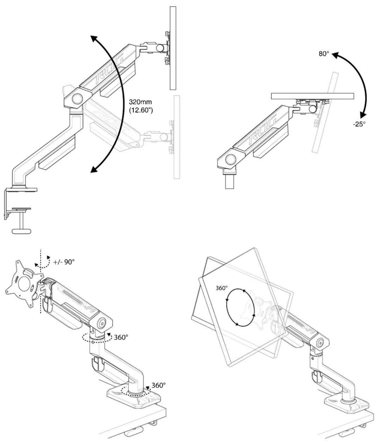
| Lift Range | 32 cm (12.6 in) |
| Tilt Range | +80° to -25° |
| Swivel Range | ±90° |
| Pivot | 360° |
| Pan | 360° |
| Rotation | 360° |
| Dimensions (Arm, W x L x H) | 57.8 x 65.6 x 15.4 cm (22.76 x 25.83 x 6.06 in) |
| Net Weight | 4.5 kg (9.9 lbs) |
| Gross Weight | 5.8 kg (12.8 lbs) |
| Material | Aluminum/Steel (typical) |
| Color | Black (assumed) |
| Cleaning | Wipe with dry cloth; do not use abrasive cleaners |
| Adjustment | Gas spring lift, tilt, swivel, pivot, rotation |
Frequently Asked Questions - AAS01 ASUS
User questions about AAS01 ASUS
0 question about this device. Answer the ones you know or ask your own.
Ask a new question about this device
Download the instructions for your Support pour écran plat in PDF format for free! Find your manual AAS01 - ASUS and take your electronic device back in hand. On this page are published all the documents necessary for the use of your device. AAS01 by ASUS.
USER MANUAL AAS01 ASUS
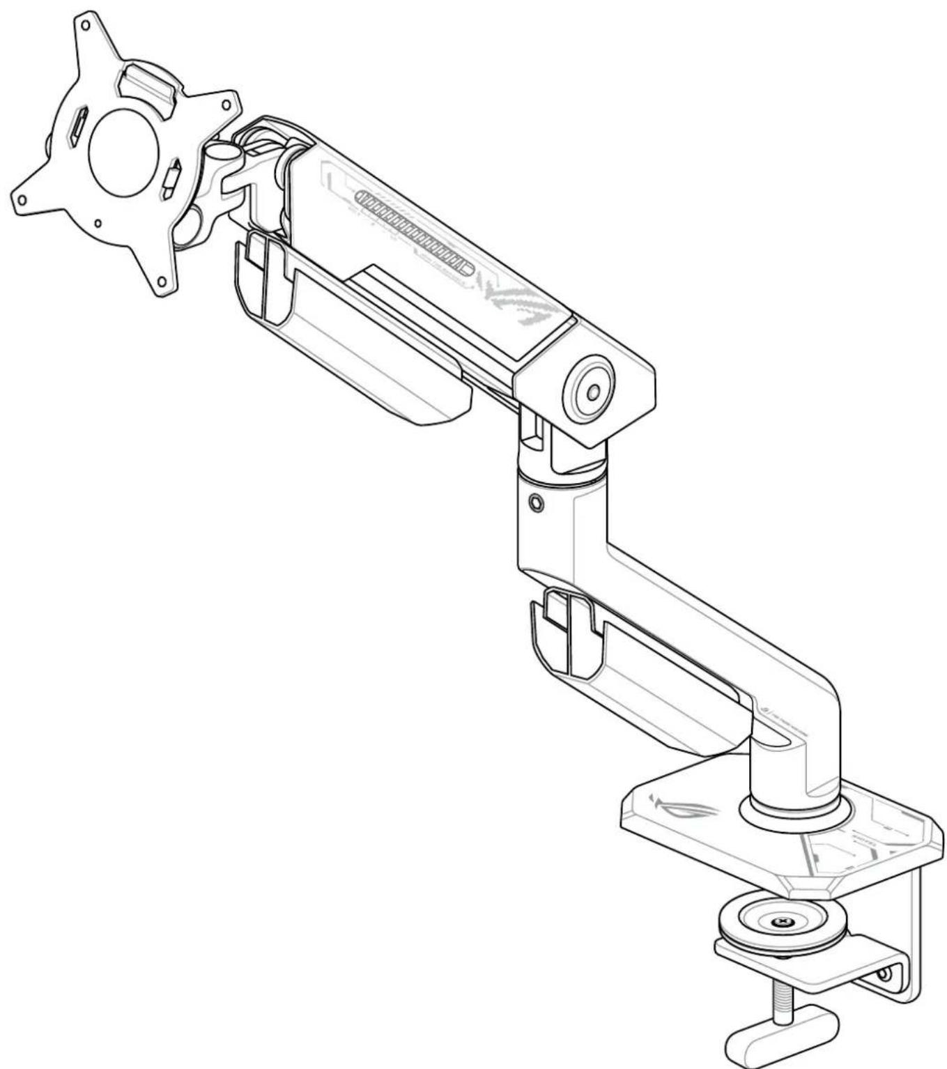
ROG ERGO MONITOR ARM (AASO1)
USER GUIDE
natural_image
Technical line drawing of a mechanical arm assembly (no text or symbols)Contents
Package contents 3
Safety Information 4
Dimensions 5
Desk placement options 8
Installation and assembly....10
Product specifications....18
Product serial number 18
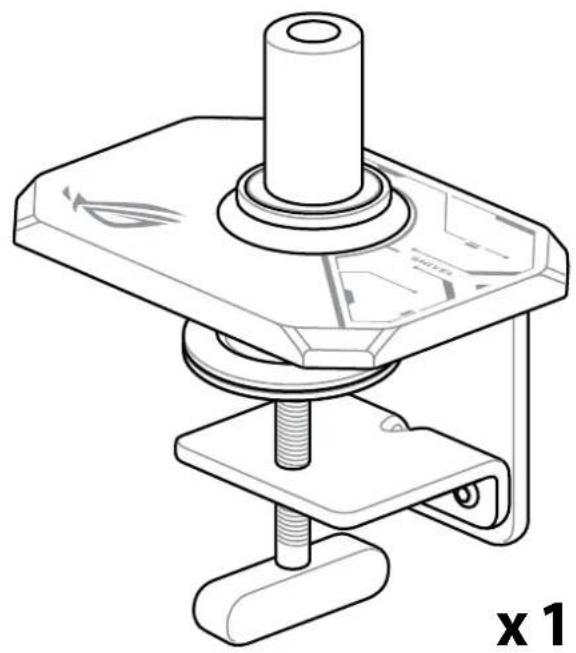
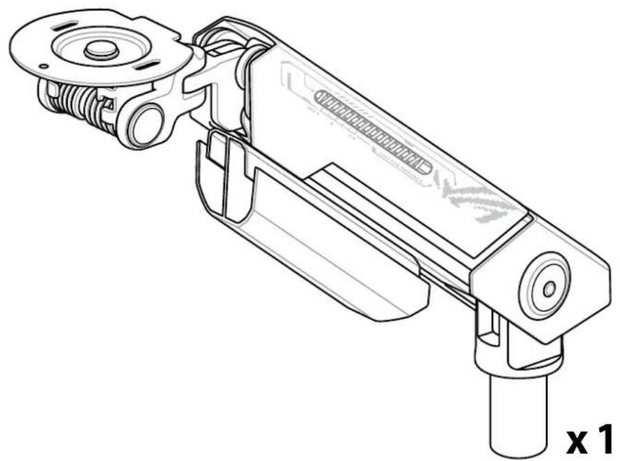
Package contents
natural_image
Technical line drawing of a mechanical clamp or holder assembly (no text or symbols)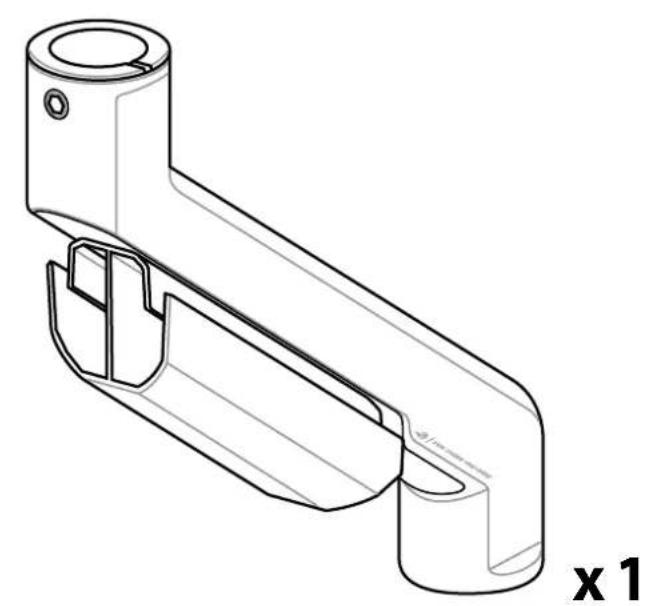
natural_image
Technical line drawing of a mechanical bracket component (no text or symbols)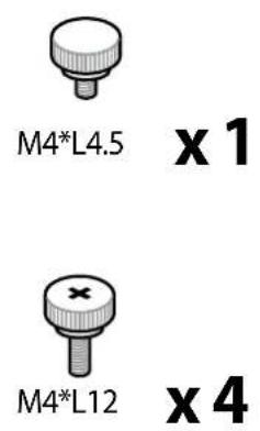
natural_image
Technical line drawing of a mechanical device with no visible text or symbols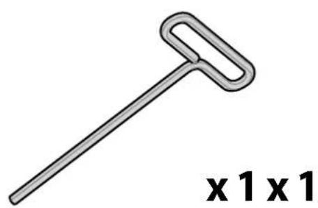
natural_image
Simple line drawing of a hammer or plunger (no text or symbols on the object itself)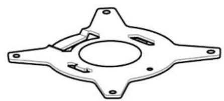
natural_image
Technical line drawing of a mechanical component with four symmetrical arms and central hole (no text or symbols)Safety Information
- Ensure to mount and assemble all the components before adjusting the position, rotation, and tilt of your monitor arm. Movement should be smooth and easy through the full range of motion and the monitor arm should stay in place once set. If this is not the case, double check that you have followed the adjustment instructions.
- Whenever equipment is added or removed from your monitor arm, leading to a change in the weight of the mounted load, repeat the adjustments steps to ensure safe and optimal operation.
- Ensure your mounting surface is strong and wide enough to support the monitor arm and mounted equipment.
- Ensure the connected cables have sufficient slack to accommodate the full range of motion.
- Ensure the connected cables are properly routed to avoid cable pinching. Cable pinching may cause damages to the monitor arm or personal injuries.
- DO NOT exceed the listed maximum weight capacity as this may cause damages to the monitor arm and mounted equipment or personal injuries.
▲ WARNING
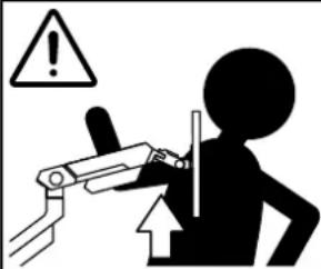
DO NOT remove mounted equipment from the monitor arm unless the monitor arm has been moved to the highest position. The monitor arm may rapidly move upwards when mounted equipment is removed, due to tension in the arm mechanism. This may cause severe personal injuries and damages to the equipment.
Dimensions

Arm at max extension Monitor mount


Arm in full up position
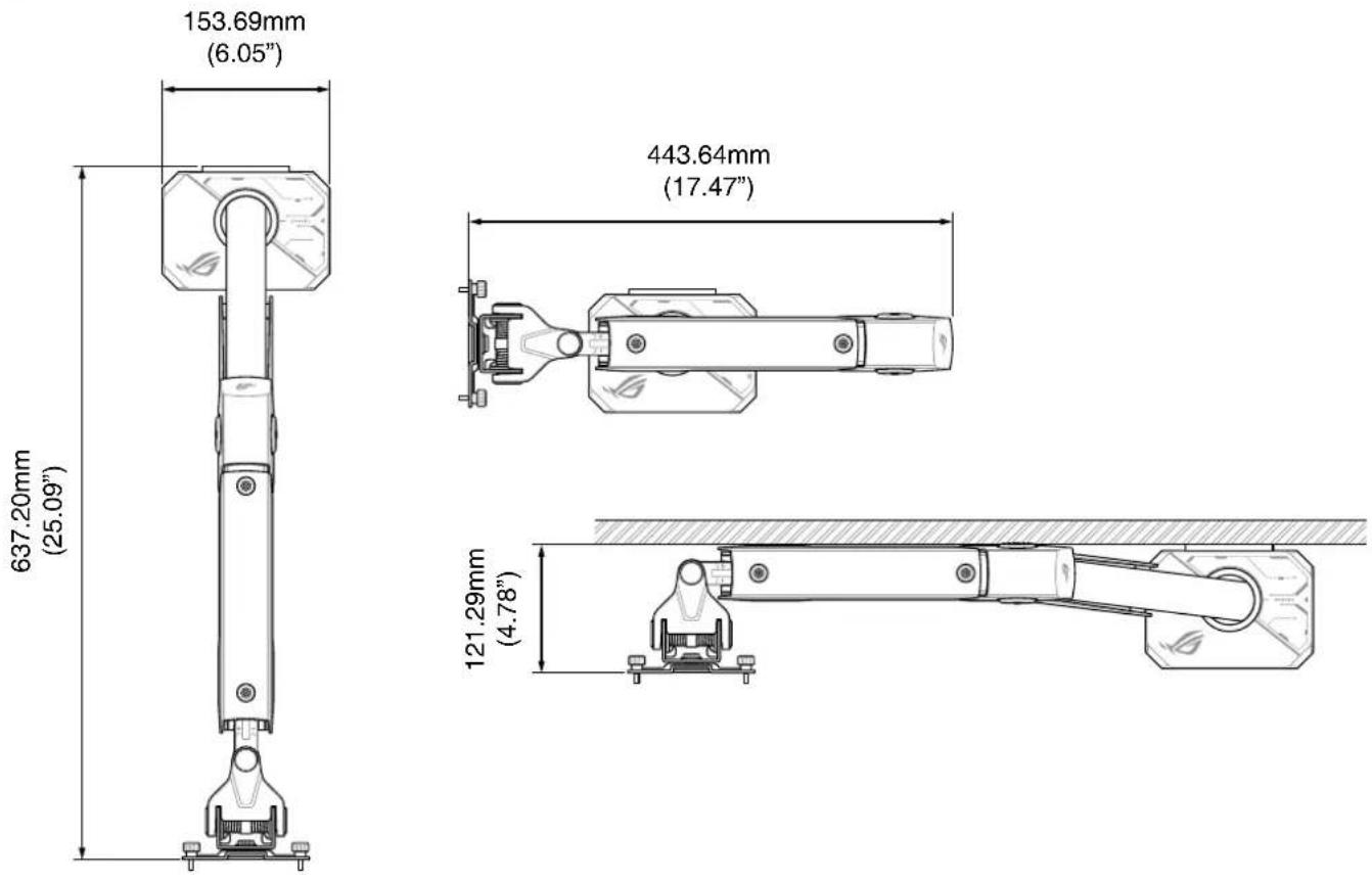

Desk clamp
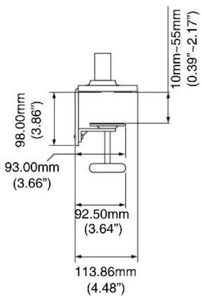
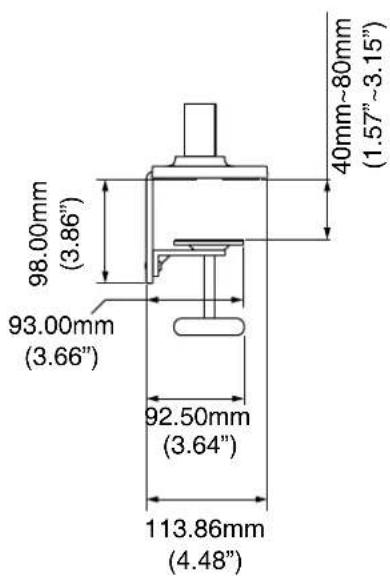
IMPORTANT! Ensure to mount and assemble all the components before adjusting the position, rotation, and tilt of your monitor arm. Movement should be smooth and easy through the full range of motion and the monitor arm should stay in place once set. If this is not the case, double check that you have followed the adjustment instructions.
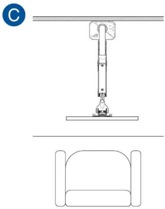
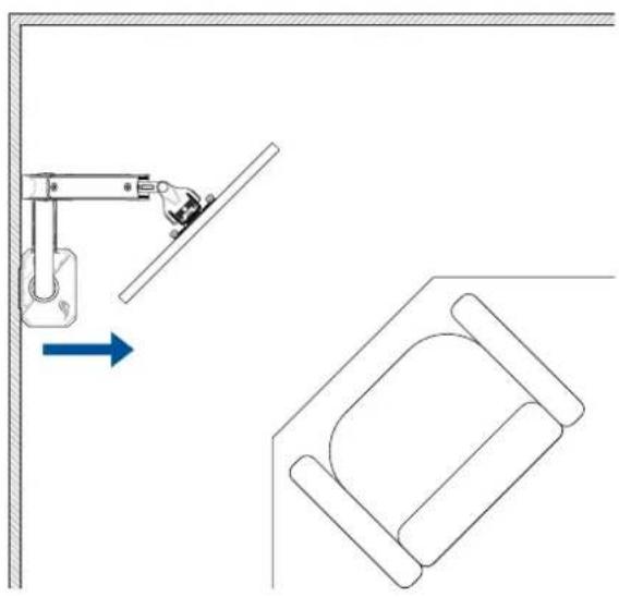
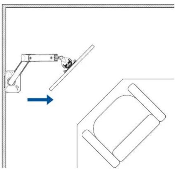
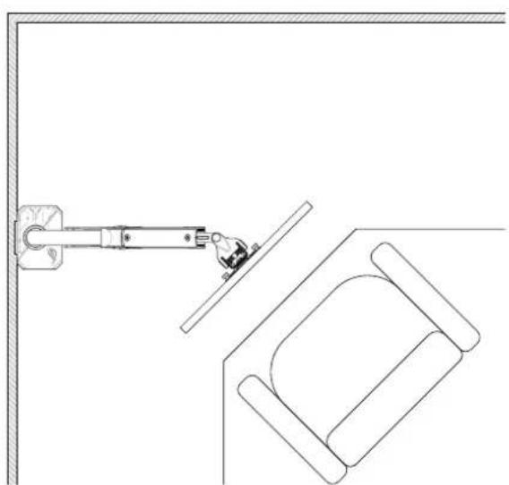
Desk placement options
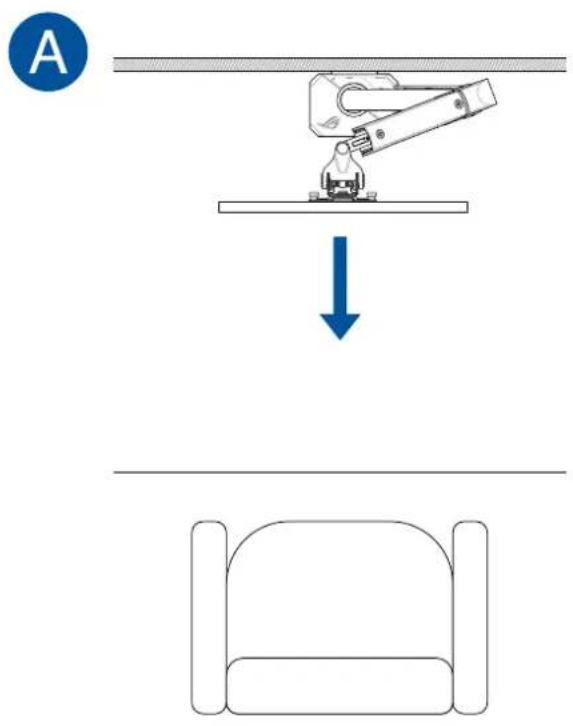
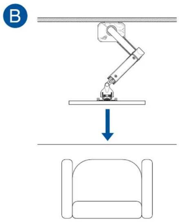
natural_image
Technical line drawing of a mechanical assembly with a vertical support and two side-view diagrams (no text or symbols)A
natural_image
Technical diagram showing a mechanical arm and a bed with directional arrows (no text or symbols)B
natural_image
Diagram showing a robotic arm interacting with a bed, with an arrow indicating direction (no text or symbols present)©
natural_image
Technical line drawing of a mechanical assembly with a lever and sofa, no text or symbols presentInstallation and assembly
1
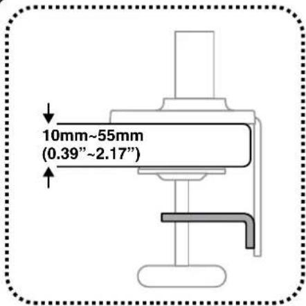
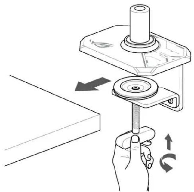
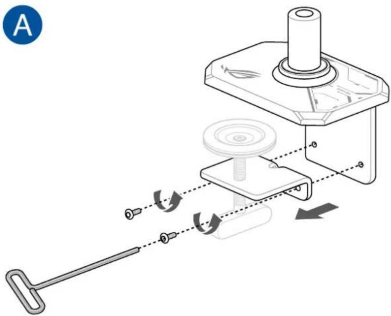
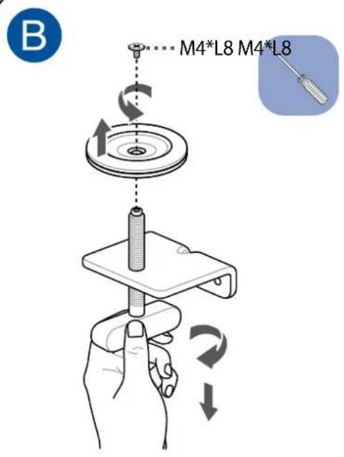
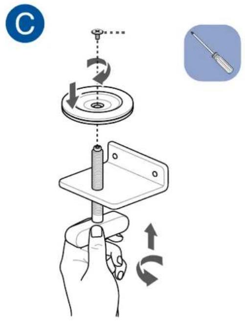
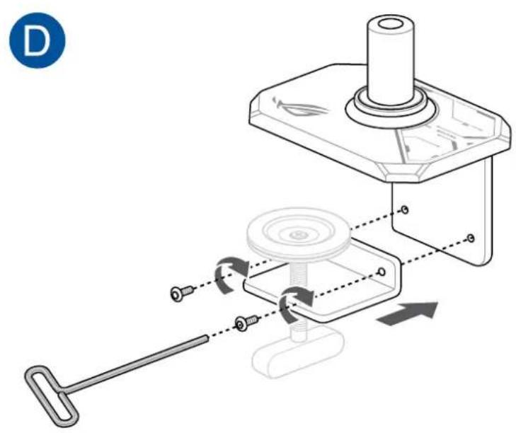
CAUTION! Ensure the C-clamp is properly aligned and pushed into the side of the surface. Failure to do so may risk the mounted equipment falling over due to unsteadiness.
natural_image
Illustration of a hand using a tool to lift a mechanical component, showing rotational motion (no text or symbols)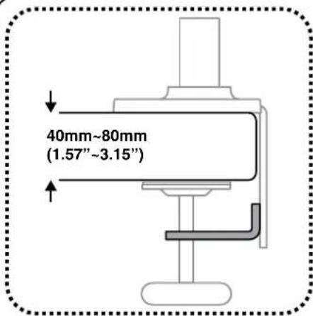
CAUTION! Ensure the C-clamp is properly aligned and pushed into the side of the surface. Failure to do so may risk the mounted equipment falling over due to unsteadiness.
natural_image
Mechanical assembly diagram showing a lever mechanism with pulley and shaft components (no text or labels)
natural_image
Diagram of a mechanical assembly with a hand holding a bolt, showing rotational motion (no text or symbols)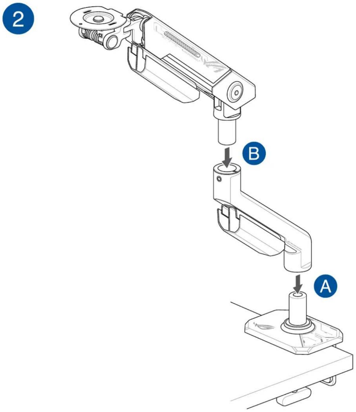
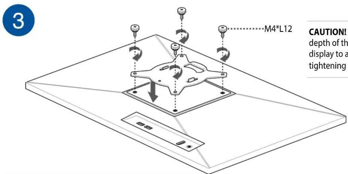
CAUTION! Take note of the depth of the screw holes on the display to avoid damage when tightening the screws.
4
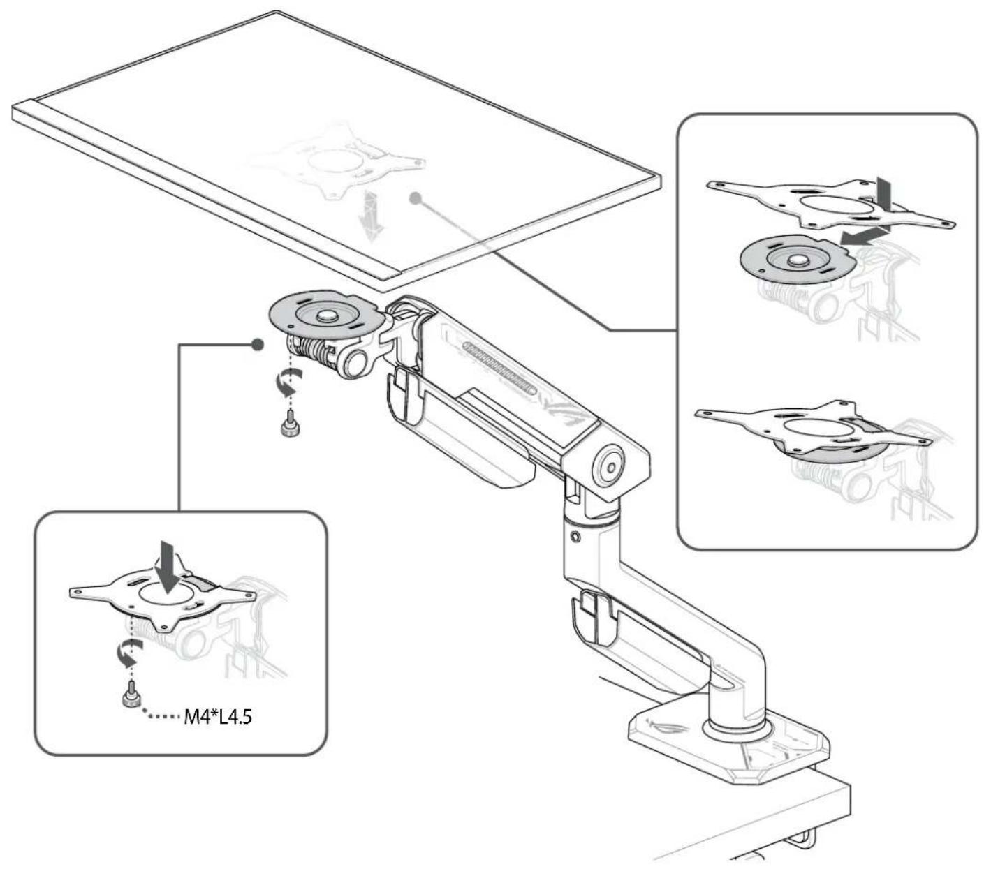
5
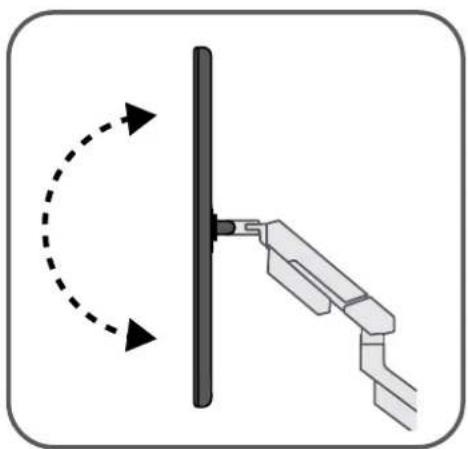
natural_image
Diagram showing a mechanical linkage with rotational motion indicated by arrows (no text or symbols)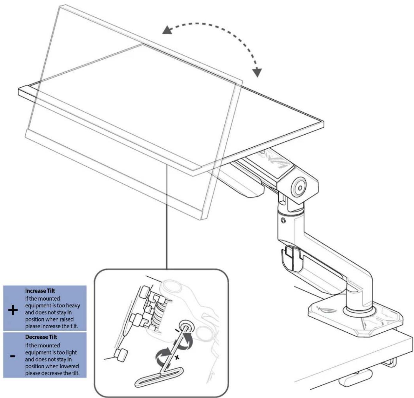
CAUTION! DO NOT overtighten or remove the screw, doing so may cause damage to the monitor arm.
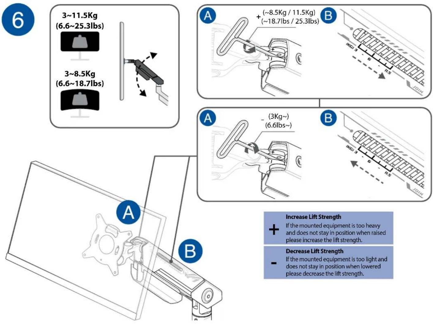
NOTE: Ensure the lift strength is adjusted according to the weight of your monitor.
CAUTION!
- DO NOT overtighten the screw, doing so may cause damage to the monitor arm.
- DO NOT exceed the listed maximum weight capacity as this may cause damage to the monitor arm and mounted equipment or personal injuries.
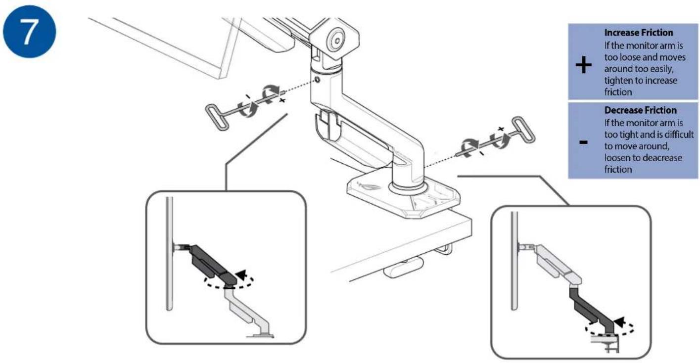
CAUTION! DO NOT remove the screw, doing so may cause damage to the monitor arm.
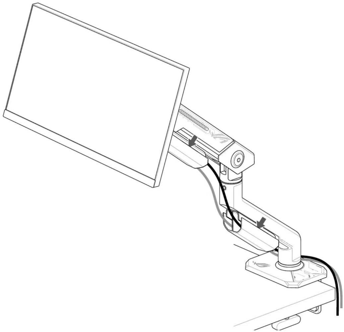
natural_image
Line drawing of a computer monitor mounted on a stand with cable, showing no text or symbolsNOTE:
- Ensure the connected cables have sufficient slack to accommodate the full range of motion.
- To remove or route cable through the cable organizer, gently pry open the cable organizer (tip of the arrow in the illustration above).
CAUTION! Ensure the connected cables are properly routed to avoid cable pinching. Cable pinching may cause damages to the monitor arm or personal injuries.
Product specifications
| Model AAS01 | ||
| Recommended Display Size | ≤34"* Display size is an approximation.** Dimension is the diagonal measurement of the display.*** The display size may be exceeded as long as the weight of the display does not exceed the maximum weight capacity of the mount. | |
| Weight Capacity | Flat display 3Kg ~ | 11.5Kg (6.6lbs ~ 25.3lbs) |
| Curved display 3Kg ~ | 8.5 Kg (6.6lbs ~ 18.7lbs)* Due to the difference in weight distribution between flat and curved display, the applicable size range of curved displays is smaller. | |
| Lift 32cm (12.6") | ||
| Tilt +80° ~ -25° | ||
| Swivel +90° ~ -90° | ||
| Pivot 360° | ||
| Pan 360° | ||
| Rotation 360° | ||
| Maximum Height 49.97cm (19.67") | ||
| Maximum Extension | 63.72cm (25.08") | |
| Physical Dimension (W x L x H) | 57.8cm x 65.6cm x 15.4cm (22.76" x 25.83" x 6.06") | |
| Box Dimension (W x L x H) | 77.5cm x 13.5cm x 23.2cm (30.51" x 5.31" x 9.13") | |
| Net Weight | 4.5Kg (9.9lbs) | |
| Gross Weight | 5.8Kg (12.8lbs) | |
| Desk Clamp Range | 10mm ~ 80mm (0.39" ~ 3.15") | |
| VESA Wall Mounting | 100mm x 100mm (3.94" x 3.94") | |
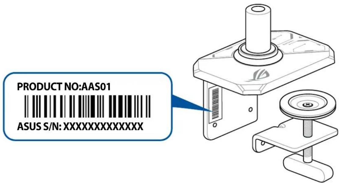
Product serial number
Please provide the product serial number when contacting customer service. Refer to the illustration below for the location of the product serial number.
Brand : ASUS
Model : AAS01
Category : Support pour écran plat