CRS700/4D - Receiver Coastal Source - Free user manual and instructions
Find the device manual for free CRS700/4D Coastal Source in PDF.


| Product Type | Multi-Zone Outdoor Receiver |
| Model | CRS700/4D |
| Brand | Coastal Source |
| Number of Zones | 4 |
| Power Output per Channel | 175W RMS @ 8Ω (stereo) |
| Total Power Output | 700W RMS |
| Minimum Impedance | 4Ω |
| Frequency Response | 20Hz - 20kHz (±0.5dB) |
| Signal-to-Noise Ratio | > 105dB |
| Total Harmonic Distortion | < 0.05% |
| Input Sensitivity | 1V RMS |
| Audio Inputs | 4x Stereo RCA, 1x Optical, 1x Bluetooth |
| Audio Outputs | 4x Speaker Binding Posts, 1x Subwoofer RCA |
| Control | IR Input, RS-232, Ethernet, Keypad Zones |
| Weather Resistance | IP66 (indoor/outdoor installation) |
| Dimensions (W x H x D) | 17 x 3.5 x 12 inches (430 x 88 x 305 mm) |
| Weight | 22 lbs (10 kg) |
| Power Supply | AC 120V-240V, 50/60Hz |
| Power Consumption | 800W maximum |
| Operating Temperature | -20°C to 50°C |
| Certifications | CE, FCC, RoHS |
| Included Accessories | Power cord, remote control, mounting brackets |
Frequently Asked Questions - CRS700/4D Coastal Source
User questions about CRS700/4D Coastal Source
0 question about this device. Answer the ones you know or ask your own.
Ask a new question about this device
Download the instructions for your Receiver in PDF format for free! Find your manual CRS700/4D - Coastal Source and take your electronic device back in hand. On this page are published all the documents necessary for the use of your device. CRS700/4D by Coastal Source.
USER MANUAL CRS700/4D Coastal Source
Data is subject to change without notice.
For the latest update, please refer to the online
version available on www.coastalsource.com.
Component Rack System
Table of Contents
1. Important safety instructions 10
2. Component Rack System 11
2:1. Welcome 11
2:2. Unpacking & checking for shipping damage 11
2:3. Disposal of the packaging material 11
2:4. List of image panels 11
3. Installation 12
3:1.Location12
3:2. Cooling 12
3:3. Cleaning 12
3:4. Precautions regarding installation 12
3:5. AC mains supply 13
3:6. Switch ON/OFF 13
3:7. Energy save 13
3:8. Breaker save 13
3:9. Remote ON/OFF (standby mode) 13
4. Connections 14
4:1. Signal grounding 14
4:2.Analog audio input connections 14
4:2.1. Remote level adjustment 14
4 : 3. Digital audio input connections 14
4:3.1. Input selection and Backup policy 14
4:4. Ethernet connections 14
4:5. Output connections 14
4:5.1. Hi-Z 70V/100V operations 14
4:6. Gain selection 15
4:7. Lo-Z 2Ω load operation 15
4 : 8. Diagnostics - GPO - Alarms 15
4:8.1. Pilot tone monitoring 15
4:8.2. Output load monitoring 15
5. LED chart 16
5:1. LED bars: signal metering 16
5:2. LED strip: system status 16
5:3. Operating mode LEDs 16
6. Control Panel 16
6:1. Selfcheck 16
6:1.1. Global faults 17
6:1.2. Channel faults 17
7. Networking 17
7:1.IP addressing 17
7:1.1. IP Addressing troubleshooting 17
8:1. Signal routing and DSP architecture 18
8:2. Purposed workflow 18
8:3. Live Impedance 18
9. Speaker Configuration 19
10. Warranty and Assistance 19
10:1. Warranty 19
10:1.1. Return of Goods 19
10:1.2. Repair or replacement 19
10:1.3. Cost and responsibility of transport 19
10:2. Assistance 19
10:2.1. In-Warranty Repairs 19
10:2.2. Out of Warranty Issues 19
10:2.3. Shipping the product to Coastal Source for Factory service 19-20
10:2.4.D.O.A Procedure 20
11. Specifications 21
A

B
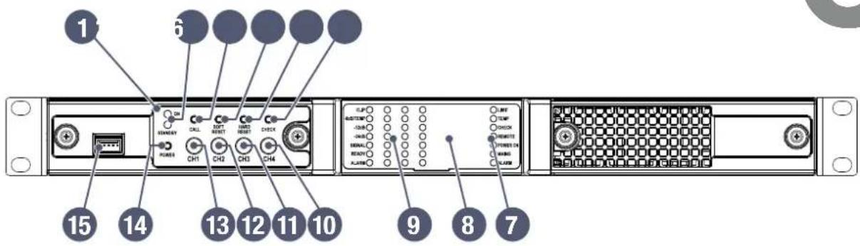
- Control panel
- ON LED and STANDBY LED
- Armonía callback push button
- Soft Reset push button
- Hard Reset push button
- Self Check
- Global status LED strip
- LED panel
- Channel status LED bars
- Channel 4 level potentiometer
- Channel 3 level potentiometer
- Channel 2 level potentiometer
- Channel 1 level potentiometer
- Power push button
- Port reserved for servicing

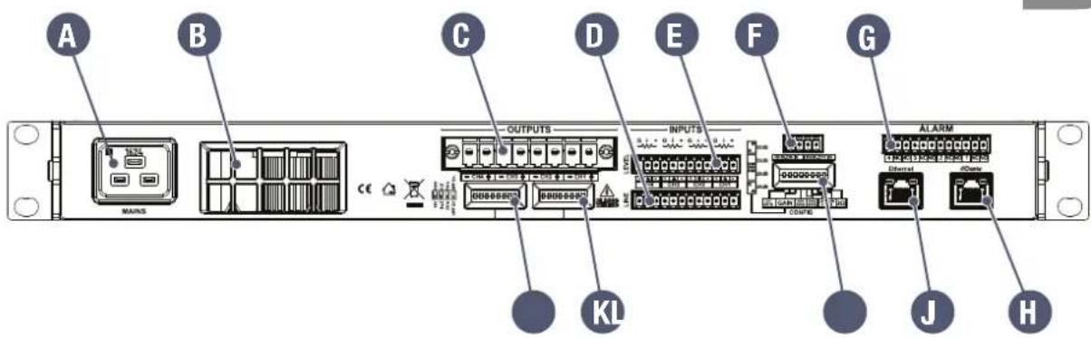
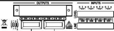
A. AC mains connector
B. Air vent
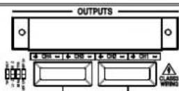
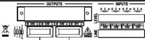
C. Output connector
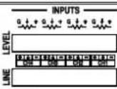
D. Line input connector
E. Remote levels connector
F. Remote on/off
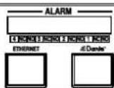
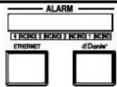
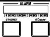
G. Alarm connector
H. Dante™ port
I. Ethernet port
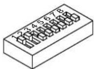
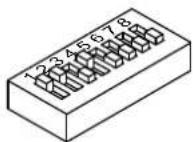
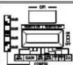
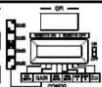
J. System configuration dip switches
K. CH1, CH2 output configuration dip switches
L. CH3, CH4 output configuration dip switches
WARNING: Connecting speakers to the incorrect channels could cause permanent speaker damage and void all warranty claims.

INPUT | CRS ADAPTER CABLES
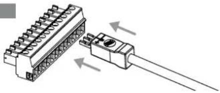
natural_image
Diagram of a connector assembly showing two connected components with arrows indicating direction (no text or symbols present)
OUTPUT | CRS ADAPTER CABLES
(sold separately)
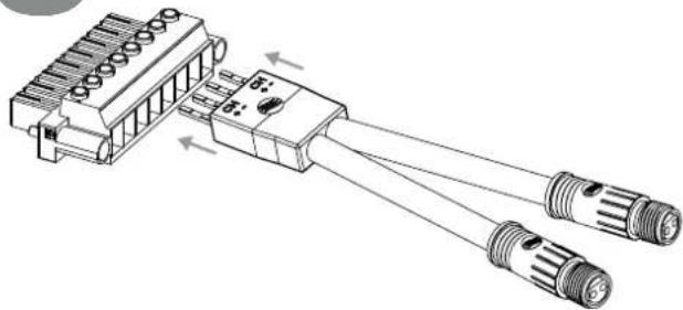
natural_image
Technical line drawing of a mechanical connector assembly with two threaded ports (no text or symbols)
INPUT | BARE WIRE
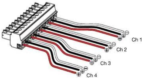
Phoenix MC 1,5/12-ST-3,81 1803675

OUTPUT | Bare wire (single ended)
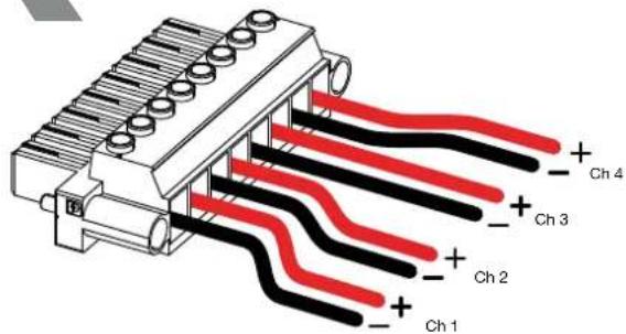
Phoenix PC 5/8-STF1-7,62 1777891

GPO/ALARM
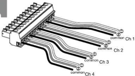
Phoenix MC 1,5/12-ST-3,81 1803675

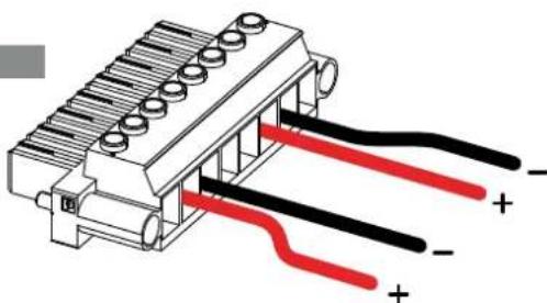
OUTPUT | Bare wire (bridged)
natural_image
Diagram of a connector with black and red wires, no text or symbols presentWARNING: Bridging the amplifier could cause permanent speaker damage. Please contact us before bridging.

REMOTE LEVEL
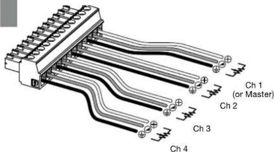
Phoenix MC 1,5/12-ST-3,81 1803675

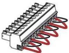
INPUT (Analog Inputs not in use)
natural_image
Illustration of a mechanical connector with coiled spring and terminal blocks (no text or symbols)
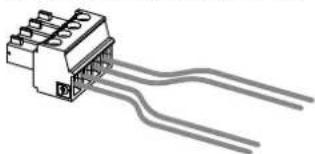
REMOTE ON | REMOTE OFF
natural_image
Pure electrical connector diagram without any text, numbers, or symbolsPhoenix MC 1,5/4-ST-3,81 1803594

Bill of connectors
Name Plug
JT Phoenix MC 1,5/12-ST-3,81 1803675
OUTPUT Phoenix PC 5/8-STF1-7,62 1777891
GPO/ALARM Phoenix MC 1,5/12-ST-3,81 1803675
REMOTE ONIOFF Phoenix MC 1,5/4-ST-3,81 1803594
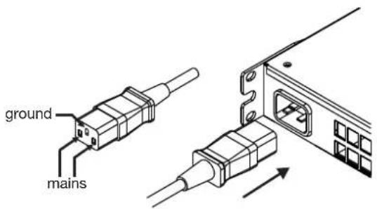
AC MAINS IEC C19

OUTPUTS
1
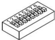
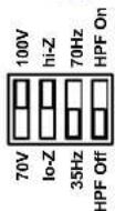
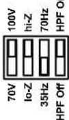
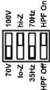
| Low-Z | High-Z | 100V | 70V | HPF@35 Hz | HPF@70 Hz | |
| 1 | ● | |||||
| 2 | ● | ● | ||||
| 3 | ● | ● | ● | |||
| 4 | ● | ● | ● | |||
| 5 | ● | ● | ||||
| 6 | ● | ● | ● | |||
| 7 | ● | ● | ● |
2
3
4
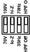
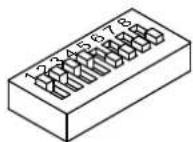
5
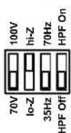
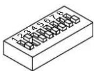
6
7
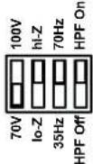
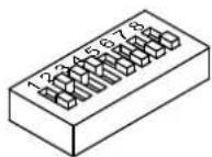
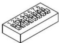
NOTE: In almost all installations, these DIP switches can be left untouched. Please call us for more information.

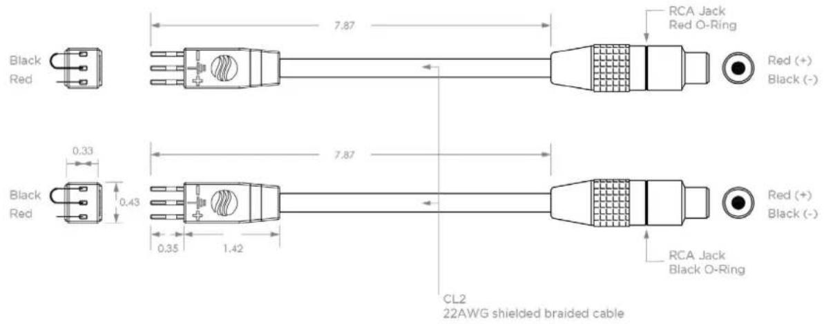
RCA INPUT CABLE ADAPTERS
(2 pairs included with each CRS Amplifier)

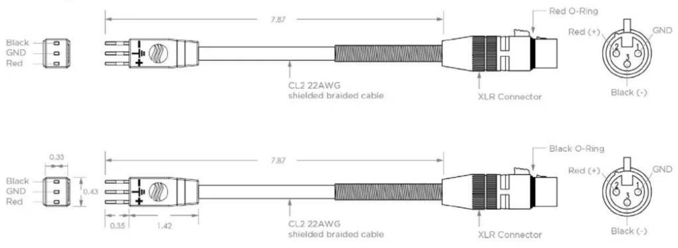
XLR INPUT CABLE ADAPTERS
(sold separately (in pairs) for balanced inputs)

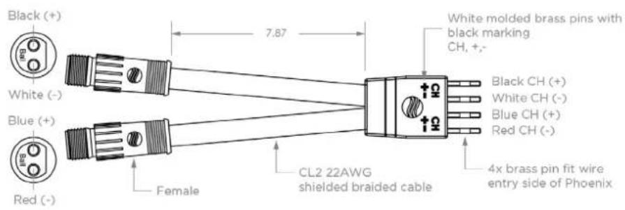
CC OUTPUT CABLE ADAPTERS
(sold separately (in pairs) for Coastal Connector outputs)

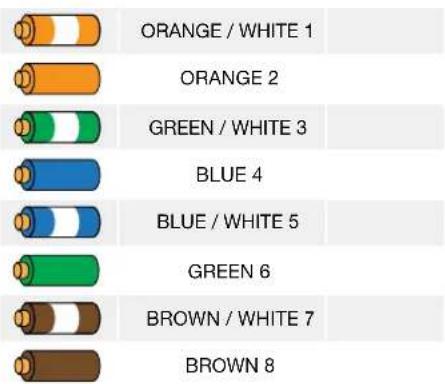
Color code (TIA/EIA-568-B) Pin
1
WEEE Directive
If the time arises to throw away your product, please recycle all possible components.
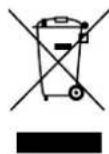
This symbol indicates that when the end-user wishes to discard this product, it must be sent to separate collection facilities for recovery and recycling. By separating this product from other household-type waste, the volume of waste sent to incinerators or land-fills will be reduced and natural resources will thus be conserved.
The Waste Electrical and Electronic Equipment Directive (WEEE Directive) aims to minimise the impact of electrical and electronic goods on the environment. Coastal Source complies with the Directive 2012/19/EU of the European Parliament on waste electrical finance the cost of treatment and recovery of electronic equipment (WEEE) in order to reduce the amount of WEEE that is being disposed of in land-fill site.
All of our CRS products are marked with the WEEE symbol; this indicates that this product must NOT be disposed of with other waste. Instead it is the user's responsibility to dispose of their waste electrical and electronic equipment by handing it over to an approved reprocessor, or by returning it to Coastal Source for reprocessing. For more information about where you can send your waste equipment for recycling, please contact Coastal Source or your local dealer.
Important Safety Instructions EXPLANATIONS OF GRAPHICAL SYMBOLS

The Lighting Flash with Arrowhead symbol within an equilateral triangle, is intended to alert the user to the presence of uninsulated "dangerous voltages" within the product enclosure that may be of sufficient magnitude to constitute a risk of shock to persons.

The Exclamation point within an equilateral triangle, is intended to alert the user to the presence of important operating and maintenance (servicing) instructions in the literature accompanying the product.

The CE-mark indicates the compliance with the low voltage and electromagnetic compatibility.

Symbol for earth/ground connection.

Symbol indicating that the equipment is for indoor use only.

Symbol for conformity with Directive 2012/19/EC of the European Parliament on waste electrical and electronic equipment (WEEE).

Do not use the unit at altitudes above 2000 m.

Do not use the unit in tropical environment.

WARNING> TO REDUCE THE RICK OF FIRE OR ELECTRIC SHOCK, DO NOT EXPOSE THIS APPARATUS TO RAIN OR MOISTURE.

DO NOT EXPOSE THIS APPARATUS TO DRIPPING OR SPLASHING AND THAT NO OBJECTS FILLED WITH LIQUID, SUCH AS VASES, SHOULD NOT BE PLACED ON THE APPARATUS.

WARNING: TO REDUCE THE RISK OF ELECTRIC SHOCK, DO NOT ATTEMPT TO OPEN ANY PART OF THE UNIT. NO USER-SERVICEABLE PARTS INSIDE. REFER SERVICING TO QUALIFIED SERVICE PERSONNEL.

CONNECTION TO THE MAINS SHALL BE DONE ONLY BY A ELECTROTECHNICAL SKILLED PERSON ACCORDING THE NATIONAL REQUIREMENTS OF THE COUNTRIES WHERE THE UNIT IS SOLD.

USE ONLY BATTERIES, CHARGERS, AND OTHER ACCESSORIES APPROVED BY POWERSOFT FOR USE WITH THIS DEVICE. PLEASE REALIZE THAT BATTERIES MIGHT CAUSE DAMAGES LIKE LEAKING, FIRE OR EXPLODE WHEN MISUSE OR DEFECTIVE. NEVER MAKE WRONG POLARITY CONNECTION WHEN CHARGING AND DISCHARGING BATTERY PACKS. ALWAYS DOUBLE CHECK POLARITY OF BATTERY'S CONNECTOR TO MAKE SURE RED WIRE TO RED WIRE AND BLACK WIRE TO BLACK WIRE.

FOR SAFETY REASON, WE USUALLY SHIP BATTERY NOT FULLY CHARGED: YOU MUST CHARGE THE BATTERY BEFORE USE.

BATTERIES (BATTERY PACK OR BATTERIES INSTALLED) SHALL NOT BE EXPOSED TO EXCESSIVE HEAT SUCH AS SUNSHINE, FIRE OR THE LIKE.

WARNING TO PREVENT INJURY, THIS APPARATUS MUST BE SECURELY ATTACHED TO THE FLOOR/WALL IN ACCORDANCE WITH THE INSTALLATION INSTRUCTIONS.

CAUTION
RISK OF ELECTRIC SHOCK DO NOT OPEN

Electrical energy can perform many useful functions. This unit has been engineered and manufactured to ensure your personal safety. But IMPROPER USE CAN RESULT IN POTENTIAL ELECTRICAL SHOCK OR FIRE HAZARD.
In order not to defeat the safeguards incorporated into this product, observe the following basic rules for its installation, use and service. Please read these "Important Safeguards" carefully before use.
Important safety instructions
-
Read these instructions.
-
Keep these instructions.
-
Heed all warnings.
-
Follow all instructions.
-
Do not use this equipment near water.
-
Clean only with a dry cloth.
-
Do not block any ventilation openings. Install in accordance with the manufacturer's instructions.
-
Do not install near any heat sources such as radiators, heat registers, stoves, or other apparatus (including amplifiers) that produce heat.
-
Do not defeat the safety purpose of the polarized or grounding-type plug. A polarized plug has two blades with one wider than the other. A grounding-type plug has two blades and a third grounding prong. The wide blade or the third prong are provided for your safety. If the provided plug does not fit into your outlet, consult an electrician for replacement of the obsolete outlet.
-
Protect the power cord from being walked on or pinched particularly at plugs, convenience receptacles, and the point where they exit from the apparatus.
-
Only use attachments/accessories specified by the manufacturer.
-
Use only with the cart, stand, tripod, bracket, or table specified by the manufacturer, or sold with the apparatus. When a cart is used, use caution when moving the cart/apparatus combination to avoid injury from tip-over.

-
Unplug this apparatus during lightning storms or when unused for long periods of time.
-
Refer all servicing to qualified service personnel. Servicing is required when the apparatus has been damaged in any way, such as power-supply cord or plug is damaged, liquid has been spilled or objects have fallen into the apparatus, the apparatus has been exposed to rain or moisture, does not operate normally, or has been dropped.
-
The apparatus shall be connected to a MAINS socket outlet with a protective earthing connection
-
Where the MAINS plug or an appropriate coupler is used as the disconnect device, the disconnect device shall remain readily operable.
Component Rack System Quick Guide
2:1. Welcome
Congratulations on buying a Coastal Source amplifier!
We know you are eager to use your new CRS amplifier, but please take a moment to read this quick guide and the safety instructions. In case you have any questions, please do not hesitate to contact your dealer or Coastal Source.
The CRS amplifier is specifically designed for installation applications. In just 1 RU, the CRS offers smaller dimensions, lighter weight and the traditionally amazing sound quality and reliability of all Coastal Source products.
CRS amplifiers implement a high efficiency microprocessor controlled power supply with built in PFC (Power Factor Correction) that allows flawless worldwide operation with any AC mains voltage in the range 85-275 V _AC tolerant to peak up to 400 V. The patented SRM (Smart Rails Management) technology allows to maximize the efficiency of the system and drastically reduce power consumption at any load and usage condition.
A secondary high efficient power supply is present to keep the system responsive at any operating condition, so that system check and monitoring can be performed even in stand-by and deep-sleep modes.
CRS is designed to work with lo-Z (from 2Ω) and with 70V/100V distributed lines: any mixed configuration of low and high impedance output loads can be realized, making the CRS suitable to all applications in installed sound reinforcement system.
The CRS amplifiers extend system performance with the support to Dante ^™ digital audio networking architecture and the on board high-end signal processing.
| 2800 140 0 700 | ||
| 8 Ω | 700 W 350 W 175 W | |
| 4 Ω | 700 W 350 W 175 W | |
| 2 Ω | 920 W 460 W 230 W | |
| Hi-Z 70 V | 700 W 350 W 175 W |
Hi-Z 100 V 700 W 350 W 175 W
2:2. Unpacking & checking for shipping damage
Your CRS amplifier has been completely tested and inspected before leaving the factory. Carefully inspect the shipping package before opening it, and then immediately inspect your new product. If you find any damage notify the shipping company or retailer immediately.
The box contains the following:
▶ 1x CRS amplifier.
▶ 1x Phoenix MC 1,5/4-ST-3,81 - 1803594 plug
▶ 2x Phoenix MC 1,5/12-ST-3,81 - 1803675 plug
▶ 1x Phoenix PC 5/8-STF1-7,62 - 1777891 plug
▶ 2x CRS RCA input cable adapters pairs
▶ 1x IEC power cord
▶ 1x Quick Start Guide
▶ 1x User Guide
2:3. Disposal of the packaging material
The protective transport packaging has been selected from materials which are environmentally friendly for disposal and can normally be recycled.
Rather than just throwing these materials away, please ensure they are offered for recycling.
2:4. List of image panels
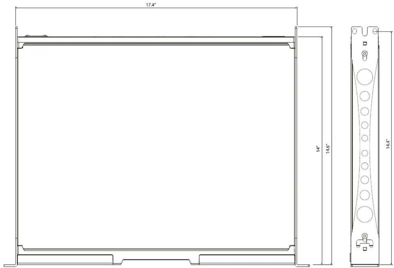
A. CRS Amplifier: all dimensions in inches
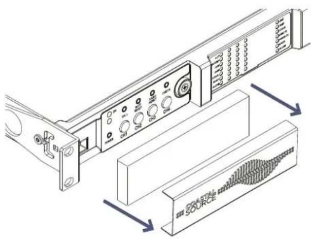
B. Front panel: how to access it
C. CRS Amplifier: Front panel description
D. CRS Amplifier: Rear panel description
E. Input | CRS Adapter cables
F. Input | Bare wire
G. GPO/Alarm
H. Remote Level
I. Remote on/Remote off
J. Output | CRS Adapter cables
K. Output connectors: wiring (single ended)
L. Output connectors: wiring (bridged mode)
M. Input (Analog Inputs not in use)
N. Output load DIP switch configurations
O. RJ45 Ethernet wiring (Color code TIA/EIA-568-B)
P. RCA Input cable adapters
Q. XLR Input cable adapters
R. CC Output cable adapters
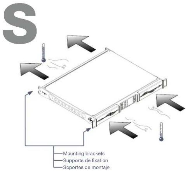
S. Air flow and mounting brackets
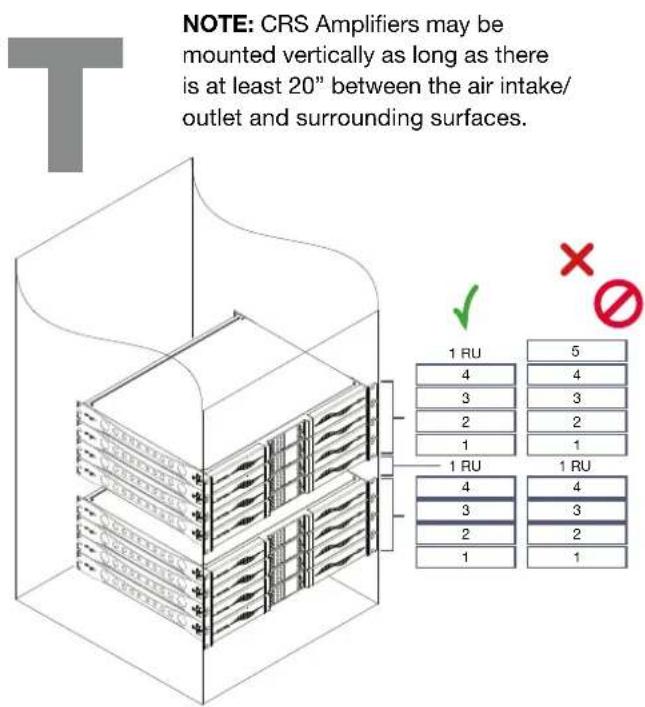
T. Rack mounting constraints
U. Regulatory information
Installation
3
3:1.Location
CRS amplifiers are meant to be installed into rack cabinets. In order to limit the risk of mechanical damages, the amplifiers must be secured to the rack using both frontal and rear mounting brackets. We recommend to use eight M6 or 12-24 UNC-2B screws for threaded holes or cage nuts.
The AC mains connector of the units must be connected to a proper circuit breaker.
Install this amplifier as far as possible from radio tuners and TV sets. An amplifier installed in close proximity of such equipment may experience noise or generic performance degradation. Placing and using the amplifier for long periods of time on heat generating sources will affect its performance. Avoid placing the amplifier on heat generating sources.
NOTE: CRS Amplifiers may be mounted vertically as long as there is at least 20" between the air intake/outlet and surrounding surfaces.
3:2.Cooling
Install the amplifier in a well-ventilated location: the ventilation openings must not be impeded by any item such as newspapers, tablecloths, curtains, etc; keep a distance of at least 20 in from the front and rear ventilation openings of the amplifier.
All Coastal Source amplifiers implement a forced-air cooling system to maintain low and constant operating temperatures. Drawn by the internal fans, air enters from the front panel and is forced over all components, exiting at the back of the amplifier.
The amplifier's cooling system features “intelligent” variable-speed DC fans which are controlled by the heat sink temperature sensing circuits: the fans speed will increase only when the temperature detected by the sensors rises over carefully predetermined values. This ensures that fan noise and internal dust accumulation are kept to a minimum.
Should however the amplifier be subject to an extreme thermal load, the fans will force a very large volume of air through the heat sink. In the extremely rare event that the amplifier should dangerously overheat, sensing circuits shut down all channels until the amplifier cools down to a safe operating temperature. Normal operation is resumed automatically without the need for user intervention.
CRS amplifiers can be stacked one on top of the other due to the efficient cooling system they are equipped with.
There is however a safety limit to be observed: in case a rack with closed back panels is used, leave one rack unit empty every four CRS amplifiers to guarantee adequate air flow (see Panel T, p. 9).
3:3.Cleaning
Always use a dry cloth for cleaning the chassis and the front panel. Air filter cleaning should be scheduled according to the dust levels in the amplifier's operating environment.

Disconnect the AC mains source before attempting to clean any part of the amplifier

In order to clean the vent filters you need to remove the front cover: never attempt to open any other part of the unit.
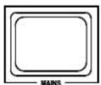
- Firmly grip the outermost blue panel and pull it outwards (see Panel B, p. 4).
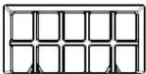
- When the front panel is removed, the air filter (looking like a shiny black plastic sponge) will be exposed.
You may use compressed air to remove the dust from filters, or wash it with clean water: in the latter case ensure that the filter is dry prior to reassembly.
3:4. Precautions regarding installation
WARNING: TO PREVENT FIRE OR ELECTRIC SHOCK
This device must be powered exclusively by earth connected mains sockets in electrical networks compliant to the IEC 364 or similar rules.
▶ Install the unit into a rack cabinet.
▶ A sectioning breaker between the mains connections and the amplifier should be installed inside the rack cabinet.
▶ Properly fit the AC mains plug to the amplifier inlet.
▶ Before powering this amplifier, verify that the correct voltage rating is being used.
▶ Verify that your mains connection is capable of satisfying the power ratings of the device.
▶ Do not use this amplifier if the electrical power cord is frayed or broken.
▶ Output terminals are hazardous: wiring connection to these terminals require installation by an instructed person and the use of ready-made leads.
▶ Take care to lock the output terminal before switching the device on.
▶ To avoid electrical shock, do not touch any exposed speaker wiring while the amplifier is operating.
▶ Do not spill water or other liquids into or on the amplifier.
▶ No naked flame sources such as lighted candles should be placed on the amplifier.
▶ Do not remove the cover. Failing to do so will expose you to potentially dangerous voltage.
The manufacturer cannot be held responsible for damages caused to persons, things or data due to an improper or missing ground connection.
▶ Contact your dealer or Coastal Source for ordinary and extraordinary maintenance.
It is absolutely necessary to verify these fundamental requirement of safety and, in case of doubt, require an accurate check by qualified personnel.
3:5.AC mains supply
CRS amplifiers implement a universal switching mode power supply with power factor correction operating in the range from 100VAC up to 240VAC ± 10% .
AC mains connection is in the rear panel through the IEC C20 inlet: the approved power cord is provided (see Panel N, p. 7).

AC mains connections must be performed only by professional or qualified personnel

ording to local electrical authorities guidelines.

This device must be powered exclusively by earth connected mains sockets in electrical works compliant to the IEC 364 or similar rule


Coastal Source recommends plugging the CRS Amplifier into a 20A rated breaker.

3:7. Energy Save
The Smart Rails Management technology implemented in the power supply unit allows it to reduce the power consumption when the input signal falls under a defined threshold.
Signal activity is monitored on the input section of the amplifier so that the system can resume normal operation in a matter of milliseconds when an incoming signal is detected on the channels. Once switched on, Energy Save is active on each channel independently.
If the signal is missing for more than 30 minutes on all channels, the auto standby is applied and the main PSU is turned off to further save energy*. Normal operation is resumed in a matter of milliseconds when an incoming signal is detected on the channels.
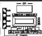
In order to activate the Energy Save feature, locate the NRG SAVE switch on the rear panel (see Panel D, p. 5) and set it ON (high).
TAB. 1 shows the power consumption in idle mode when the Energy save is either enabled or disabled.
| Energy Save | 115 V AC mains 230 V | AC mains | |||||
| Current | Real Power | Apparent Power | Current | Real Power | Apparent Power | ||
| CRS2800/4 | OFF | 0.5 A | 33.6 W | 76 VA | 0.35 A | 33.7 W | 145 VA |
| AUTOSTBY | 0.47 A | 20 W | 55 VA | 0.57 A | 21 W | 131 VA | |
| CRS1400/4 | OFF | 0.45 A | 32.7 W | 70 VA | 0.29 A | 31.8 W | 140 VA |
| AUTOSTBY | 0.46 A | 20 W | 53 VA | 0.46 A | 20 W | 106 VA | |
| CRS700/4 | OFF | 0.45 A | 33.6 W | 70 VA | 0.29 A | 32.8 W | 140 VA |
| AUTOSTBY | 0.46 A | 20 W | 53 VA | 0.46 A | 20 W | 106 VA | |
TAB. 1: Idle consumption.
3:8.Breaker save
In case the power grid is unable to provide enough current to continuously drive the loads, or when the number of attached amplifier to the same AC mains is such that one can reach the critical power absorption from the line, it is possible to activate the Breaker Save feature.
When activated, the Breaker Save feature reduces *Time out time is selectable via Armonia in DSP+D Versions
(halves) the maximum continuous current absorption from the mains. This slightly reflects on the overall performance of the system reducing the available output power.
In order to activate the Breaker Save feature, locate the BRK SAVE switch on the rear panel (see Panel D, p. 5) and set it ON (high).
3:6.Switch ON/OFF
Once properly powered (power cord inserted, sectioning breaker closed), the system can be either ON or in STANDBY mode depending on its state at last power off.
In order to toggle between ON and STANDBY press and hold the power button for 3 seconds (see Panel C, p. 5). Please consider that the operating condition can be modified by the REMOTE ON and REMOTE OFF configuration (see §3 : 9.Remote ON/OFF (standby mode).
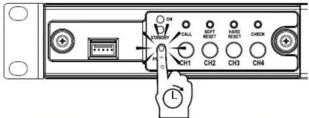
FIG. 1: Press and hold the power button for 3 seconds to toggle between ON and STANDBY.
3:9.Remote ON/OFF (standby mode)
Remote ON/OFF is available through the dedicated terminals on the rear panel (see Panel D, p. 5).
Both terminals respond to the differential voltage between the contacts: a voltage difference in the range 5V_DC - 24V_DC triggers the control. Any voltage exceeding 28V_DC may damage the input circuitry.
The couple of terminals act depending on the actual state of the amplifier, as shown in.
| REMOTE ON | REMOTE OFF | AMPLIFIER STATE |
| Vdiff ≥ 5V | Any | Force Turn ON |
| Vdiff < 3V | Vdiff ≥ 5V | Force Turn OFF |
| Vdiff < 3V | Vdiff < 3V | No Change(Keep either standby or in current state) |
In order to remotely toggle between standard operating and standby modes, the AC mains power must be connected.
Connections
4
Make sure the external breaker is off before attempting to make any input or output connections.
By using good quality input and output speaker cables, the likelihood of erratic signal behavior is reduced to a minimum. Whether you make them or buy them, look for good quality wires, connectors and soldering techniques.
Coastal Source includes (2) pairs of RCA input cables with each CRS amplifier for factory quality input connections. Other input and output cables are available separately for completely factory I/O connections.
4:1. Signal grounding
There is no ground switch or terminal on the CRS amplifiers. All shield terminals of input connections are directly connected to the chassis. This means that the unit's signal grounding system is automatic. In order to limit hum and/or interference entering the signal path, use balanced input connections.
In the interests of safety, the unit MUST always operate with electrical safety earth connected to the chassis via the dedicated Protective Earth ♦wire.
4:2. Analog audio input connections
Analog input connections are made via the Phoenix MC 1,5/12-ST-3,81 1803675 connector. Signal polarity of analog input connections is shown in Panel F, p. 6.
Short the Positive (+) and Negative (-) to the Ground Input terminal on the unused Input channel(s) in order to avoid picking up noise.
4:2.1. Remote level adjustment
The level of each channel of the CRS amplifiers can be remotely adjusted by means of a linear 10 kΩ potentiometer connected to the input LEVEL connector (see Panel D, p. 5) through a Phoenix MC 1,5/12-ST-3,81 1803675 plug. The right polarity for the connections is shown in Panel H, p. 6.
When the CH1 MSTR switch is in the OFF position (low) the remote level potentiometers work independently on each separate channel.
When the CH1 MSTR switch is in the ON position (high) the remote level potentiometer of the channel 1 acts as a master level, controlling the volume of all the four channels.
The remote level controls are in series with the level adjustment knobs in the front panel.
4:3. Digital audio input connections
The CRS amplifiers accept four input streams from the Dante connection through the Dante port. Cabling must comply to TIA/EIA-568-B and adopt the T568B scheme pinout, as shown in Panel U, p. 9.
In order to implement a Dante network, a computer running Dante Controller has to be used. Dante Controller is a software application that manages devices on the network. CRS amplifiers are automatically discovered and displayed in Dante Controller with the default identifier MODELNAME-SERIAL (e.g. CRS2800-71520).
4:3.1.Input selection and Backup policy
With CRS amplifiers, it is possible to select among two input signal sources per channel: analog and Dante streams. The Armonía Pro Audio Suite software provides an interface to select the proper input source, manage input gain and delay of the analog and digital sources, in order to compensate transmission latency and levels.
Furthermore, CRS amplifiers implement a backup policy aimed to improve reliability against signal fault. By assigning a bus priority to the two different input sources per channel, the system is able to automatically switch to a reliable input connection in case of signal drop or pilot tone mismatch.
4:4. Ethernet connections
The port labeled Ethernet is designed to remotely control the amplifier via an Ethernet connection through a personal computer and Armonía Pro Audio Suite software. A complete interface for signal routing, sound shaping, and performance fine tuning is provided.
Coastal Source recommend the use of Ethernet Cat5 straight through - patch - cables with pin/pair assignments TIA/EIA-568-B, i.e. T568B, as shown in Panel U, p. 9.
4:5. Output connections
WARNING: Connecting speakers to the incorrect channels could cause permanent speaker damage and void all warranty claims.

CLASS3 WIRING
CLASS3 Output terminals are hazardous: wiring connection to WIRING these terminals require installation by an instructed person and the use of ready made leads. Take care to secure the output terminal before switching the device on.
Output connections are made via the Phoenix PC 5/8-STF1-7,62 1777891: single-ended wirings for lo-Z loudspeaker and Hi-Z distributed lines connections are shown in Panel K, p. 6. Bridge-tied connection of lo-Z loudspeaker is supported on adjacent channel pairs 1-2, 3-4, 5-6 and 7-8; inputs must be physically paralleled as shown in Panel L, p. 6.
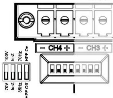
Any mixed configuration of low and high impedance output loads can be made: in order to set the load configuration, each channel is provided by four DIP switches (refer to Panel O, p. 7). CRS Amplifiers are configured to drive Lo-Z loads by factory default.
4:5.1.Hi-Z 70V/100V operations
Any channel of a CRS amplifier can drive 70V/100V (Hi-Z) distributed line of loudspeakers. In order to connect any channel's output to a 70V/100V line, the rear panel DIP switch corresponding to the channel must be correctly set as indicated in Panel O, p. 7.
Coastal Source recommends to use the built-in HPF (High Pass Filter) when the amplifier is set to drive a distributed line to prevent loudspeaker transformer saturation which can considerably degrade sound performance. The HPF can be activated by means of the DIP switch corresponding to the channel (see Panel O, p. 7), two cutting frequency are available 35 Hz and 70 Hz.
4:6.Gain selection
The CRS amplifiers can operate with different gain applied to the input signal. This feature is designed to match the voltage of the input signal, i.e. allowing to obtain the same output power at different input levels.
| GAIN | Input sensitivity @ 8Ω load | ||
| Vpeak Vrms dBu | |||
| 2800/4 | 26 6.92 4.9 16.0 | ||
| 29 4.90 3.47 13.0 | |||
| 32 3.46 2.45 10.0 | |||
| 35 2.45 1.74 7.0 | |||
| 1400/4 | 26 4.89 3.46 13.0 | ||
| 29 3.48 2.46 10.0 | |||
| 32 2.45 1.74 7.0 | |||
| 35 1.74 1.23 4.0 | |||
| 700/4 | 26 3.46 2.45 10.0 | ||
| 29 2.46 1.74 7.0 | |||
| 32 1.72 1.23 4.0 | |||
| 35 1.23 0.87 1.0 | |||
TAB. 2: Input sensitivity.
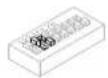
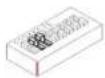
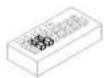
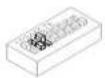
A proper combination of the position of two GAIN switches on the rear panel sets the operating gain of the amplifier (see TAB. 3)
| 26 dB | 29 dB | 32 dB | 35 dB |
 |  |  |  |
| Bread | Bread | Bread | Bread |
TAB. 3: Setting the GAIN.
4:7.Lo-Z 2Ω load operation
The CRS amplifiers are optimized for working with 4Ω output loads but a special configuration allows to connect low loads down to 2Ω (e.g. in the configuration with three paralleled 8Ω loudspeakers that provides 2.67Ω load to the output channel).
The 2Ω switch (see Panel D, p. 5) allows to activate on all output channels set to match low impedance (i.e. in Lo-Z configuration) an operating condition that optimizes the performance with very low loads, by limiting the maximum output voltage to 85 V _peak per channel.
For optimal 2Ω performance, it is recommended to select LowZ mode for all the amplifier's channels
4:8. Diagnostics - GPO - Alarms
The amplifier's GPO – general purpose output – system
implements triggering signals to broadcast alarms.
CRS amplifiers provide a pair of paralleled general purpose output connections per channel: one Normally Open ⊕ NO and one Normally Closed ⊗ NC.
The connections are available on the back panel via the 12-pin Phoenix MC 1.5/12-ST-3.81 1803675 connector: see Panel G, p. 6 for wirings.
These contacts are used to report potentially dangerous faults or generally unsafe operation conditions by toggling alarm switches relative to the following events, and any fault preventing the normal operation of an output channel:
▶ No AC mains (i.e. system shutdown);
▶ Thermal stress: the system temperature is too high and the thermal protection is engaged;
▶ Short circuit in output wiring: either the loudspeaker or the line is in short;
▶ Amplifier is in Standby
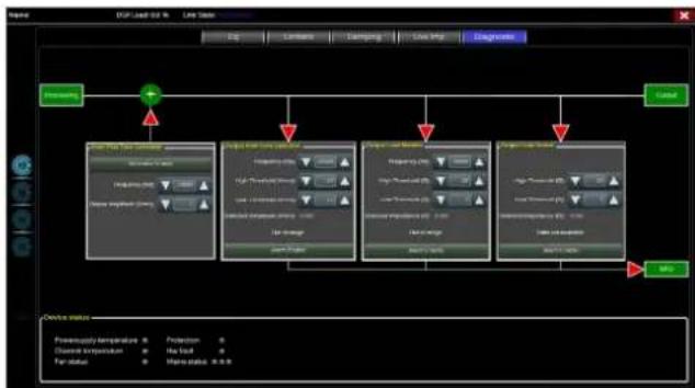
CRS amplifiers features further monitoring on pilot tone and output load: the monitoring and diagnostic interface
flowchart
graph TD
    A["Input"] --> B["Control"]
    B --> C{Condition}
    C -->|Yes| D["Output 1"]
    C -->|No| E["Output 2"]
    D --> F["Pressure: 1000V, Current: 50A"]
    E --> G["Pressure: 1000V, Current: 50A"]
    F --> H["Pressure: 1000V, Current: 50A"]
    G --> I["Pressure: 1000V, Current: 50A"]
FIG. 2: Diagnostic panel in Armonía Pro Audio Suite.
is accessible in Armonía Pro Audio Suite software through the Diagnostic tab in the output ways panel of the selected channel of the CRS amplifier.
4:8.1. Pilot tone monitoring
Thanks to the built-in DSP, the CRS amplifiers implement pilot tone detection and alert. Detecting and alerting features are available for both input and output pilot tones on each channel.
The detection of a mismatch in the input pilot tone parameters (frequency and voltage level) can be used to trigger the backup policy and activate an alert through the general purpose output switch.
The output pilot tone detection relies on an external signal passing through the amplifier or the internal post DSP pilot tone generator; in both cases any mismatch between the detected signal and the set thresholds triggers the general purpose output switches.
4:8.2. Output load monitoring
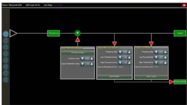
Through the Armonía Pro Audio Suite software it is possible to set the thresholds on the load impedance, at given frequency, that trigger the general purpose output of any channel in the CRS amplifiers.
LED chart
5
The front LED panel of the amplifier includes four LED bars for output signal metering and one LED strip with status indicators. Two operating mode LEDs are located on the control panel under the left hand cover.
5:1.LED bars: signal metering
The four left hand LED bars provide signal metering and channel status for channels 1 to 4 left to right.
| Color | Signal metering | Warnings Lighting Description | ||
| ORANGE | Clipping *Limiter Engaged | — | Custom speaker limiters engaged | |
| YELLOW | -6dB SOLID ON | Thermal warning Thermal protection engaged | ||
| GREEN | -12dB — — | |||
| GREEN | -24dB — — | |||
| GREEN | -60dB | SOLID ON Signal presence BLINKING Channel muted | ||
| GREEN | — | SOLID ON Channel ready | ||
| FLASHING Auto Standby | ||||
| RED | — | SOLID ON Channel fault FLASHING User Diagnostic Fault | ||
The "CLIP" LED on the CRS amplifiers is illuminated any time that our pre-programmed limiters are engaged. These limiters are designed to maximize both SPL and the life of the drivers. This does not indicate actual clipping or damage to the amp or speakers.
1 Red LED lights on in case of any kind of channel fault that prevents the normal channel operating; at the same time the rear corresponding GPO toggles the contacts NO into NC and NC into NO.
5:2.LED strip: system status
The right hand LED strip on the LED panel provides system status informations.
| Color Name | Warnings | |||
| Lighting Description | ||||
| ORANGE | LIMIT | FLASHING Breaker Save Enabled | ||
| SOLID ON | Breaker Save limiting power draw | |||
| YELLOW | TEMP | SOLID ON | Thermal warning Thermal protection engaged | |
| ORANGE | CHECK | SOLID ON | System self checking | |
| BLINKING | Self check completed | |||
| FAST BLINKING | Self Check Unavailable | |||
| GREEN | REMOTE | SOLID ON | Connected to Armonia or 3rd Party Remote Control | |
| FLASHING | Preset Changed / Disconnected | |||
| GREEN | POWER ON | SOLID ON | System ready | |
| OFF | System off | |||
| GREEN | MAINS | SOLID ON | AC mains voltage within the operating range | |
| OFF | Undervoltage | |||
| FLASHING | Over/Undervoltage Warning | |||
| FAST BLINKING | Overvoltage | |||
| SLOW BLINKING | Mains FUSES blown | |||
| RED | ALARM | SOLID ON | PSU fault OR Critical Faults | |
1 Red LED lights on in case of any kind of PSU fault that prevents normal operating.
5:3.Operating mode LEDs
The operating mode LEDs are located on the control panel. They state the operating mode when the system either is on or in standby mode.
| Color Name | Operating mode | |||
| Standby | Power on | |||
| GREEN | POWER ON | — | SOLID ON | |
| ORANGE | STANDBY | SOLID ON | — | |
| ORANGE | AUTO STANDBY | BLINKING | — | |
| ORANGE | ERROR CODE | BLINK COUNTER | — | |
Control Panel
6
The control panel is located under the left hand metal cover. See Panel B, p. 4 on how to access the control panel.
The control panel contains two LEDs (for the description see §5:3.Operating mode LEDs) and the following controls.
The push-buttons are disabled when connected to Armonia.
| Label | Type | Action | Description |
| POWER | Pushbutton | keep pressed for 3 seconds | Toggle system ready/standby mode |
| CALL | Pushbutton | press | Highlight the amplifier in the Armonía workspace |
| SOFT RESET1 | Pushbutton | keep pressed for 3 seconds | Reset network parameters to factory default |
| HARD RESET1 | Pushbutton | keep pressed for 3 seconds | Reboot the system |
| CHECK2 | Pushbutton | keep pressed for 3 seconds | Start the self-checking procedure* |
| CH13 | Potentiometer | turn counter-clockwise | Attenuate the output level of the signal on channel 1 |
| CH23 | Potentiometer | turn counter-clockwise | Attenuate the output level of the signal on channel 2 |
| CH33 | Potentiometer | turn counter-clockwise | Attenuate the output level of the signal on channel 3 |
| CH43 | Potentiometer | turn counter-clockwise | Attenuate the output level of the signal on channel 4 |
- Keep pressed both the SOFT RESET button and the HARD RESET button for at least 3 seconds to completely reset the amplifier to its factory default configuration (any preset stored in the internal memory will be lost and replaced with a flat preset).
- For further information see §6:1. Self check.
- The potentiometer is in series with the remote level control (see §4:2.1. Remote level adjustment) so it can be used to limit the output volume regardless to any remote adjustment.
* Press again to resume normal operations
6:1.Self check
The self check procedure tests the amplifier status and reports the user in case of failures.

It is highly recommended to unplug the output connectors before proceeding with the self check procedure


The testing signals might cause loudspeaker impairments.

After few minutes, at the end of the self check procedure, a combination of lighten LED in the LED panel provide information about the amplifier status.
In order to exit the self check test and resume normal operations, press once the self check push button.
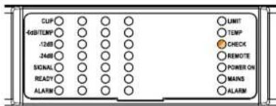
FIG. 3: System OK.
6:1.1.Global faults
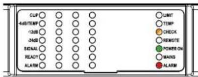
FIG. 4: Power supply fault
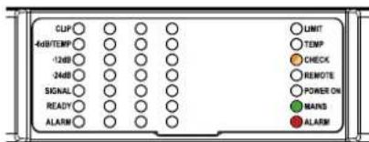
FIG. 5: AC Mains voltage out of range (over/ under voltage)
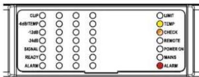
FIG. 6: PSU temperature out of range
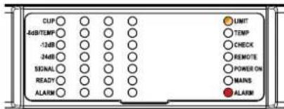
FIG. 7: Fan Error
6:1.2.Channel faults
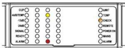
FIG. 8: Channel# Temperature out of range
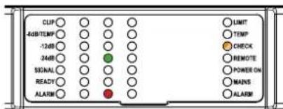
FIG. 9: Channel# Output Waveform non-conformity
If self check cannot be started because of a fault, the check LED will blink fast, whilst a reassuring slow blink is an indication of a completed self check procedure.
Networking
7
CRS amplifiers support star network topology via the Ethernet port and Dante networking via the Dante port only.
The Ethernet port is designed to allow the remote control of the amplifier through Armonía Pro Audio Suite and third party software. The Dante port is reserved to Dante networking.
7:1.IP addressing
Factory default network settings are DHCP/AutoIP, in order for the amplifier to self-configure when connected to an existing LAN or PC. Fixed IP policy can also be adopted and configured through Armonía Pro Audio Suite.
If a DHCP server is not active within the network, the amplifier platform initiates a stateless address auto-configuration (i.e. Zero-configuration networking methodology – Zeroconf): it self assigns a local numeric network address (of the type 169.254.x.y – 172.31.*.* for the secondary network if present – with a subnet mask 255.255.0.0) and automatically distributes and resolves the host names of the networking devices. For setting a static IP address please refer to the Armonía Pro Audio Suite user guide.
7:1.1.IP Addressing troubleshooting
When connecting the CRS to a network environment it may happen that Armonía Pro Audio Suite does not discover or import the amplifier.
Usually this is a problem of IP addressing: both Armonia and the amplifier must belong to the same subnet. If a DHCP server is present on the network and a CRS amplifier is in AUTO IP, networking may become unstable.
As a rule of thumb, turn the DHCP server on before connecting the amplifiers.
IP addressing of a CRS amplifier is established during the bootstrap: when the amplifier discovers a DHCP server on the network during the startup, it negotiates the networking parameters. If the amplifier does not reveal a DHCP server on the network during the startup, it set itself in AUTO IP mode.
Armonía Pro Audio Suite is the default configuring interface that allows system setting and customization of the CRS amplifiers.
Armonía can be installed on a PC running Windows (XP SP3 and higher). Freely download Armonía Pro Audio Suite from the Armonía forum:
https://armonia.powersoft.it/download-armonia/
CRS amplifiers can connect to the PC running Armonía through a Fast Ethernet connection. In order to start remote operation the device must be discovered and imported into the Armonía Workspace. Click on the Discover button in the Remote entities window, or select it from the Model list and drag it into the Armonía Workspace.
The callback button (see Panel C, p.5) allows you to highlight the presence of the amplifier into the Armonía Workspace.
Once connected to Armonía Pro Audio Suite, a double click on the amplifier icon in the Workspace will open the amplifier dashboard. Here it is possible to access and configure all the features of the CRS amplifier.
8:1. Signal routing and DSP architecture
Signal processing on CRS amplifiers accomplishes multiple functions that affect the audio signal before power amplification; the main adjustments include gain, polarity, delay, limiting and signal equalization; some processing are related only to particular stages, such as limiting and damping control that are implemented on the output section only, or input priority assignment available in the input section.
The processing architecture is composed of six sections:
▶ Input source selection. The input section allows you to manage input gain and delay of analog and digital sources, in order to compensate transmission latency and levels. Furthermore the CRS amplifiers implement a backup policy aimed to improve reliability against signal fault.
▶ Matrix. The innovative routing engine of CRS amplifiers allows any input to be routed to any output. The Matrix implements a non-boolean rooting architecture allowing free channel assignment and level adjustment.
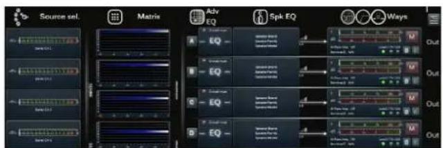
FIG. 10: Armonía Pro Audio Suite.
▶ Advanced processing. This allows you to optimize levels and shape the sound of the input signals. Gain and polarity adjustment, asymmetric raised-cosine full parametric filters, delay and mute are available on each channel routed to the speaker section.
▶ Speaker equalization. Designed to manage the configuration presets for multi-way systems, it implements FIR and IIR full parametric filters.
▶ Speaker routing. Once properly grouped, the output channels are presented to the matrix as speakers – a single row representing a speaker (actually group of ways) – allowing a high grade of granularity in signal processing.
▶ Output processing. This allows fine tuning of output signals, aiming to optimize the power delivered and the performance of the single way out. It provides gain and polarity adjustment, IIR and FIR full parametric filters, delay, mute, limiting and damping control on each output channel.
8:2. Purposed workflow
Once the loudspeaker layout has been defined, we suggest a bottom-up configuration procedure that starts from the configuration of the transducers layout and goes up toward the input selection and the definition of the backup policy.
Shortly, the main steps to follow are:
- Set Lo-Z and Hi-Z loads and filters on output channels.
- Load the loudspeaker presets or manually configure the loudspeaker layout (grouping output channels, limiting, speaker processing, etc.).
- Define the routing path and the levels of the signals from the input channels to the active output channels (matrix).
- Select the signal source from the input connections and define the backup policy (input source selection).
- Define GPO assignment and alarms thresholds.
8:3. Live Impedance
Through Armonía Pro Audio Suite software it is possible to set the thresholds on the load impedance, at given frequency, that trigger the general purpose output of any channel in CRS amplifiers (see FIG. 5).
flowchart
graph TD
    A["Input Data"] --> B["Processing"]
    B --> C["Data Analysis Module"]
    C --> D["Output Module"]
    D --> E["Storage"]
    style A fill:#f9f,stroke:#333
    style B fill:#ccf,stroke:#333
    style C fill:#cfc,stroke:#333
    style D fill:#fcc,stroke:#333
    style E fill:#cff,stroke:#333
FIG. 11: GPO: System monitoring interface.
▶ CRS amplifier potentiometers attenuate the speakers gain (see Panel C, p. 5): they modify the overall gain applied to the group of ways belonging to the selected speaker. The amount of gain attenuation (External gain) is shown in Armonía Pro Audio Suite.
Speaker Configuration
9
Utilizing the Armonía Pro Audio Suite, Coastal Source ships all CRS amplifiers with a custom DSP configuration for the exact speaker setup that was ordered with the amplifier. Each pre-loaded speaker preset has been specially tuned to optimize performance from the amplifier and speaker itself. The top of the amplifier bears a Speaker Configuration label that outlines the programmed output configuration based on your original order.
In addition to the pre-loaded speaker presets, each CRS amp ships with the preset for the entire Coastal Source speaker line. If the system changes down the road, contact Coastal Source for instructions on how to change presets from one speaker type to another. This can be done quickly utilizing the Armonía web app.
NOTE: Coastal Source outdoor audio systems are the clearest and most efficient on the market, but they are not designed to run at 100% volume full-time. If the system is going to be played at loud volumes for an extended period of time, Coastal Source recommends setting the volume to 75-80%.
Warranty and Assistance
10
10:1.Warranty
Coastal Source guarantees its manufactured products to be free from defective components and factory workmanship for a period of time starting from the date of purchase printed on Coastal Source's (or any of its Authorized Dealer's) invoice to the end customer. The standard warranty period are:
5 years for CRS amplifiers.
All warranty repairs and retrofits must be performed by Coastal Source at no cost for the purchaser. Warranty exclusion: Coastal Source's warranty does not cover product malfunctioning or failure caused by: misuse, abuse, repair work or alterations performed by non-authorized personnel, incorrect connections, exposure to harsh weather conditions, mechanical damages (including shipping accidents), and normal wear and tear. Coastal Source will perform warranty services provided that the product is not damaged during transportation.
10:1.1. Return of Goods
Goods can be returned to Coastal Source only after they have been granted a Return Merchandise Authorization (RMA) number to be attached to the external packaging. Coastal Source has the right to refuse any returned good without a RMA number.
10:1.2. Repair or replacement
Coastal Source reserves the right to repair or replace any defective goods covered by product warranty at its sole discretion and as it deems best.
10:1.3. Cost and responsibility of transport
The purchaser (or end user/customer) is solely responsible for all transportation costs and risks associated with sending warranty covered goods to Coastal Source or its Authorized Service Center. Coastal Source will assume full responsibility and cover all costs incurred to send the goods back to the purchaser (or end user/customer).
10:2.Assistance
There are no user-serviceable parts in the amplifier. If your amplifier needs repair, contact your Coastal Source dealer. You can also contact the Coastal Source Technical Service department directly.
After having applied the aforementioned procedure, Coastal Source or your dealer will provide the shipment details and the product's warranty status.
10:2.1. In-Warranty repairs:
The service repair will be free of charge for the customer.
10:2.2. Out of Warranty Issues
▶ The service costs are calculated on the local rate applied by Coastal Source.
The repair time has been set from Coastal Source and it's equally applied in all cases.
The unit will be evaluated by a technician, and Coastal Source will provide the customer with the estimated costs. The repair will only take place once the customer has approved the estimated costs. The customer will pay the shipping charges once the repair has been completed, depending on the countries' standard procedures.
For any inquiries please contact Coastal Source customer care warranty@coastalsource.com.
10:2.3. Shipping the product to Coastal Source for Factory service
▶ Take a note of each serial number of the units to be returned.
▶ Fill out completely the defect report form for each unit to be returned.
▶ Send the completed defect report form to the following email address:
warranty@coastalsource.com
After having applied the aforementioned procedure, you will receive an Email containing the Return Merchandise Authorization (RMA form) for each unit returned.
All returned Coastal Source units must be shipped to the following address:
Coastal Source
1270 Glen Avenue
Moorestown, NJ 08057
Phone: 1-800-719-1996
Email: warranty@coastalsource.com
Phone Support Hours
Monday - Friday 9AM to 5PM EST
10:2.4.D.O.A. Procedure
In case of a D.O.A. (Dead On Arrival) product, we kindly request the customer to contact the local dealer where the product was purchased or the Factory service centre, mentioning the serial number of the faulty unit.
D.O.A. unit will be replaced completely without any additional charges!
Important Note: Do not tamper with or operate the D.O.A. unit in any ways in order to avoid any warranty issue.
Coastal Source declines any D.O.A warranty service if the returned unit has been tampered with or misused by the customer.
Specifications
CRS2800/4
Channel Handling
| Number of output channels | 4 Hi-Z or Lo-Z (bridgeable per ch. pair) | Phoenix PC 5/8-STF1-7,62 |
| Number of input channels | ||
| Analog | 4 | Phoenix MC 1,5/12-ST-3,81 |
| DanteTM* | 4 | 1 x RJ45 |
Audio
| Gain 26 dB 29 dB 32 dB 35 dB | ||||
| Input sensitivity @ 8 Ω | 4.9 V | 3.47 V | 2.45 V | 1.73 V |
| Max input level | 20 dBu | |||
| Frequency Response ( ±0.5 dB , 1 W @ 8 Ω) | 20 Hz - 20 kHz | |||
| Crosstalk (1 kHz) | typical -70 dB | |||
| S/N (32 dB gain, analog input 20 Hz - 20 kHz @ 8 Ω) | >110 dB(A) | |||
| Input impedance | 20 kΩ balanced | |||
| THD+N (from 0.1 W to Full Power) | < 0.1%(typical < 0.05%) | |||
| DIM (from 0.1 W to Full Power) | < 0.05% | |||
| Slew Rate (input filter bypassed @ 8 Ω) | >50 V/μs | |||
| Damping Factor @ 8 Ω, 20 Hz - 100 Hz | >500 | |||
DSP*
| AD converters | 24 Bit TandemTM @ 48 kHz125 dB-A Dynamic Range - 0.005 % THD+N |
| DA converters | 24 Bit TandemTM @ 48 kHz117 dB-A Dynamic Range - 0.003 % THD+N |
| Sample rate converter | 24 Bit @ 44.1 kHz to 192 kHz140 dB Dynamic Range - 0.0001 % THD+N |
Internal precision 32 bit floating point
Latency 2.5 ms fixed latency architecture
Memory/Presets 128 MB (RAM) plus 512 MB flash for presets
Delay 2 s (input) + 100 ms (output) for time alignment
| Equalizer | Raised-cosine, custom FIR, parametric IIR: peaking, hi/lo-shelfing, all-pass, band-pass, band-stop, hi/lo-pass |
| Crossover | linear phase (FIR), Butterworth, Linkwitz-Riley, Bessel: 6 dB/oct to 48 dB/oct (IIR) |
| Limiters TruePowerTM, RMS voltage, RMS current, Peak limiter | |
| Damping control | Active DampingControlTM and LiveImpedanceTM measurement |
Networking
Standards compliance auto-sensing Fast Ethernet (IEEE 802.3u, 100 Mbit/s)
Supported topologies Star
| Maximum output power per channel @ 8 Ω | 700 W |
| Maximum output power per channel @ 4 Ω | 700 W |
| Maximum output power per channel @ 2 Ω | 920 W |
| Maximum output power @ 4 Ω Bridged | 1840 W |
| Maximum output power @ 8 Ω Bridged | 1400 W |
| Maximum output power @ Hi-Z distributed line 100 V | 700 W |
| Maximum output power @ Hi-Z distributed line 70 V | 700 W |
| Maximum unclipped output voltage @ 8 Ω | 139 V_peak |
| Maximum output current | 45 A_peak |
The power figure is calculated by driving and loading symmetrically all the channels: uneven loads allow to achieve higher performances.
AC Mains Power
| Power supply | Universal regulated switch mode with PFC, SRM | |||
| Nominal voltage (±10%) | 100-240 V @ 50-60Hz | |||
| Power factor (>500 W output) | >0.95 | |||
| Consumption/current draw | @ 115 V | @ 230 V | ||
| Idle | 32.3 W | 0.45 A | 32.4 W | 0.33 A |
| Idle (DSP+D) | 33.6 W | 0.5 A | 33.7 W | 0.35 A |
| 1/8 Max Output Power @ 4 Ω | 850 W | 9.16 A | 826.8 W | 5.02 A |
| 1/4 Max Output Power @ 4 Ω | 1718 W | 15.96 A | 1651 W | 9.41 A |
| AC Mains connector | IEC C20 inlet (20 A max)region-specific power cord provided | |||
Thermal
| Operating temperature | 14° - 95° F / -10° - 35° C | |||
| Cooling | Fan, continuously variable speed,temperature controlled, front to rear airflow | |||
| Thermal dissipation | @ 115 V | @ 230 V | ||
| Idle | 110.3 BTU/h | 27.8 kcal/h | 110.6 BTU/h | 27.9 kcal/h |
| Idle (DSP+D) | 114.7 BTU/h | 28.92 kcal/h | 115.1 BTU/h | 29.02 kcal/h |
| 1/8 Max Output Power @ 4 Ω | 853.5 BTU/h | 215.2 kcal/h | 768.1 BTU/h | 193.7 kcal/h |
| 1/4 Max Output Power @ 4 Ω | 1768.5 BTU/h | 445.9 kcal/h | 1539.8 BTU/h | 388.3 kcal/h |
Construction
| Dimensions | 19.0 x 1.75 x 14.1 in483 x 44.5 x 358 mm |
| Weight | 15.4 lb (7.0 Kg) |


Channel Handling
| Number of output channels | 4 Hi-Z or Lo-Z(bridgeable per ch. pair) | Phoenix PC 5/8-STF1-7,62 |
| Number of input channels | ||
| Analog | 4 | Phoenix MC 1,5/12-ST-3,81 |
| DanteTM* | 4 | 1 x RJ45 |
Audio
| Gain 26 dB 29 dB 32 dB 35 dB | ||||
| Input sensitivity @ 8 Ω | 3.46 V | 2.46 V | 1.73 V | 1.23 V |
| Max input level | 20 dBu | |||
| Frequency Response ( ±0.5 dB , 1 W @ 8 Ω) | 20 Hz - 20 kHz | |||
| Crosstalk (1 kHz) | typical -70 dB | |||
| S/N (32 dB gain, analog input 20 Hz - 20 kHz @ 8 Ω) | >108 dB(A) | |||
| Input impedance | 20 kΩ balanced | |||
| THD+N (from 0.1 W to Full Power) | < 0.1%(typical < 0.05%) | |||
| DIM (from 0.1 W to Full Power) | < 0.05% | |||
| Slew Rate (input filter bypassed @ 8 Ω) | >50 V/μs | |||
| Damping Factor @ 8 Ω, 20 Hz - 100 Hz | >500 | |||
DSP
| AD converters | 24 Bit TandemTM @ 48 kHz125 dB-A Dynamic Range - 0.005 % THD+N |
| DA converters | 24 Bit TandemTM @ 48 kHz117 dB-A Dynamic Range - 0.003 % THD+N |
| Sample rate converter | 24 Bit @ 44.1 kHz to 192 kHz140 dB Dynamic Range - 0.0001 % THD+N |
Internal precision 32 bit floating point
Latency 2.5 ms fixed latency architecture
Memory/Presets 128 MB (RAM) plus 512 MB flash for presets
Delay 2 s (input) + 100 ms (output) for time alignment
| Equalizer | Raised-cosine, custom FIR, parametric IIR: peaking, hi/lo-shelving, all-pass, band-pass, band-stop, hi/lo-pass |
| Crossover | linear phase (FIR), Butterworth, Linkwitz-Riley, Bessel: 6 dB/oct to 48 dB/oct (IIR) |
| Limiters TruePowerTM, RMS voltage, RMS current, Peak limiter | |
| Damping control | Active DampingControlTM and LiveImpedanceTM measurement |
Networking
Standards compliance auto-sensing Fast Ethernet (IEEE 802.3u, 100 Mbit/s)
Supported topologies Star
| Maximum output power per channel @ 8 Ω | 350 W |
| Maximum output power per channel @ 4 Ω | 350 W |
| Maximum output power per channel @ 2 Ω | 460 W |
| Maximum output power @ 4 Ω Bridged | 920 W |
| Maximum output power @ 8 Ω Bridged | 700 W |
| Maximum output power @ Hi-Z distributed line 100 V | 350 W |
| Maximum output power @ Hi-Z distributed line 70 V 350 W | |
| Maximum unclipped output voltage @ 8 Ω | 100 V_peak |
| Maximum output current | 45 A_peak |
The power figure is calculated by driving and loading symmetrically all the channels: uneven loads allow to achieve higher performances.
AC Mains Power
| Power supply | Universal regulated switch mode with PFC, SRM | |||
| Nominal voltage (±10%) | 100-240 V @ 50-60Hz | |||
| Power factor (>500 W output) | >0.95 | |||
| Consumption/current draw | @ 115 V | @ 230 V | ||
| Idle | 31.4 W | 0.40 A | 31.6 W | 0.28 A |
| Idle (DSP+D) | 32.7 W | 0.45 A | 31.8 W | 0.29 A |
| 1/8 Max Output Power @ 4 Ω | 442 W | 4.2 A | 438 W | 2.39 A |
| 1/4 Max Output Power @ 4 Ω | 878 W | 8.02 A | 849 W | 4.41 A |
| AC Mains connector | IEC C20 inlet (20 A max)region-specific power cord provided | |||
Thermal
| Operating temperature | 14° - 95° F / -10° - 35° C | |||
| Cooling | Fan, continuously variable speed,temperature controlled, front to rear airflow | |||
| Thermal dissipation | @ 115 V | @ 220 V | ||
| Idle | 107.2 BTU/h | 27.0 kcal/h | 107.9 BTU/h | 27.2 kcal/h |
| Idle (DSP+D) | 111.6 BTU/h | 28.1 kcal/h | 112.0 BTU/h | 28.2 kcal/h |
| 1/8 Max Output Power @ 4 Ω | 484.8 BTU/h | 122.2 kcal/h | 471.2BTU/h | 118.8 kcal/h |
| 1/4 Max Output Power @ 4 Ω | 949.1 BTU/h | 239.3 kcal/h | 850.1 BTU/h | 214.3 kcal/h |
Construction
| Dimensions | 19.0 x 1.75 x 14.1 in483 x 44.5 x 358 mm |
| Weight | 15.0 lb (6.8 Kg) |

Channel Handling
| Number of output channels | 4 Hi-Z or Lo-Z (bridgeable per ch. pair) | Phoenix PC 5/8-STF1-7,62 |
| Number of input channels | ||
| Analog | 4 | Phoenix MC 1,5/12-ST-3,81 |
| DanteTM* | 4 | 1 x RJ45 |
Audio
| Gain 26 dB 29 dB 32 dB 35 dB | ||||
| Input sensitivity @ 8 Ω | 2.45 Vrms | 1.74 Vrms | 1.22 Vrms | 0.87 Vrms |
| Max input level | 20 dBu | |||
| Frequency Response ( ±0.5 dB , 1 W @ 8 Ω) | 20 Hz - 20 kHz | |||
| Crosstalk (1 kHz) | typical -70 dB | |||
| S/N (20 Hz - 20 kHz A-Weighted @ 8 Ω) | >104 dB | |||
| Input impedance | 20 kΩ balanced | |||
| THD+N (from 0.1 W to Full Power) | < 0.1%(typical < 0.05%) | |||
| DIM (from 0.1 W to Full Power) | < 0.05% | |||
| Slew Rate (input filter bypassed @ 8 Ω) | >50 V/μs | |||
| Damping Factor @ 8 Ω, 20 Hz - 100 Hz | >500 | |||
DSP
| AD converters | 24 Bit TandemTM @ 48 kHz125 dB-A Dynamic Range - 0.005 % THD+N |
| DA converters | 24 Bit TandemTM @ 48 kHz117 dB-A Dynamic Range - 0.003 % THD+N |
| Sample rate converter | 24 Bit @ 44.1 kHz to 192 kHz140 dB Dynamic Range - 0.0001 % THD+N |
Internal precision 32 bit floating point
Latency 2.5 ms fixed latency architecture
Memory/Presets 128 MB (RAM) plus 512 MB flash for presets
Delay 2 s (input) + 100 ms (output) for time alignment
| Equalizer | Raised-cosine, custom FIR, parametric IIR: peaking, hi/lo-shelving, all-pass, band-pass, band-stop, hi/lo-pass |
| Crossover | linear phase (FIR), Butterworth, Linkwitz-Riley, Bessel: 6 dB/oct to 48 dB/oct (IIR) |
| Limiters TruePowerTM, RMS voltage, RMS current, Peak limiter | |
| Damping control | Active DampingControlTM and LiveImpedanceTM measurement |
Networking
Standards compliance auto-sensing Fast Ethernet (IEEE 802.3u, 100 Mbit/s)
Supported topologies Star
| Maximum output power per channel @ 8 Ω | 175 W |
| Maximum output power per channel @ 4 Ω | 175 W |
| Maximum output power per channel @ 2 Ω | 230 W |
| Maximum output power @ 4 Ω Bridged | 460 W |
| Maximum output power @ 8 Ω Bridged | 350 W |
| Maximum output power @ Hi-Z distributed line 100 V | 175 W |
| Maximum output power @ Hi-Z distributed line 70 V | 175 W |
| Maximum unclipped output voltage @ 8 Ω | 70 V_peak |
| Maximum output current | 33 A_peak |
The power figure is calculated by driving and loading symmetrically all the channels: uneven loads allow to achieve higher performances.
AC Mains Power
| Power supply | Universal regulated switch mode with PFC, SRM | |||
| Nominal voltage (±10%) | 100-240 V @ 50-60Hz | |||
| Power factor (>500 W output) | >0.95 | |||
| Consumption/current draw | @ 115 V | @ 230 V | ||
| Idle | 31.4 W | 0.40 A | 31.6 W | 0.28 A |
| Idle (DSP+D) | 32.7 W | 0.45 A | 32.8 W | 0.29 A |
| 1/8 Max Output Power @ 4 Ω | 301 W | 2.75 A | 302 W | 1.65 A |
| 1/4 Max Output Power @ 4 Ω | 556 W | 5.47 A | 553 W | 3.02 A |
| AC Mains connector | IEC C20 inlet (20 A max)region-specific power cord provided | |||
Thermal
| Operating temperature | 14° - 95° F / -10° - 35° C | |||
| Cooling | Fan, continuously variable speed,temperature controlled, front to rear airflow | |||
| Thermal dissipation | @ 115 V | @ 220 V | ||
| Idle | 107.2 BTU/h | 27.0 kcal/h | 107.9 BTU/h | 27.1 kcal/h |
| Idle (DSP+D) | 111.6 BTU/h | 28.1 kcal/h | 108.6 BTU/h | 27.3 kcal/h |
| 1/8 Max Output Power @ 4 Ω | 344.8 BTU/h | 86.8 kcal/h | 348.2 BTU/h | 87.6 kcal/h |
| 1/4 Max Output Power @ 4 Ω | 53 2.6 BTU/h | 134.0 kcal/h | 522.3 BTU/h | 131.4 kcal/h |
Construction
| Dimensions | 19.0 x 1.75 x 14.1 in483 x 44.5 x 358 mm |
| Weight | 15 lb (6.8 Kg) |


COASTAL
SOURCE
[ defy the elements ]
Coastal Source
1270 Glen Avenue
Moorestown, NJ 08057
Tel: 1-800-719-1996
General inquiries: info@coastalsource.com
Service & maintenance: warranty@coastalsource.com
www.coastalsource.com
- Component Rack System
- Table of Contents
- Important safety instructions 10
- Component Rack System 11
- Installation 12
- Connections 14
- LED chart 16
- Control Panel 16
- Networking 17
- Speaker Configuration 19
- Warranty and Assistance 19
- Specifications 21
- Bill of connectors
- 1
- WEEE Directive
- Important Safety Instructions EXPLANATIONS OF GRAPHICAL SYMBOLS
- CAUTION
- Important safety instructions
- Component Rack System Quick Guide
- 2:1. Welcome
- 2:2. Unpacking & checking for shipping damage
- 2:3. Disposal of the packaging material
- 2:4. List of image panels
- Installation
- 3
- 3:1.Location
- 3:2.Cooling
- 3:3.Cleaning
- Disconnect the AC mains source before attempting to clean any part of the amplifier
- 3:4. Precautions regarding installation
- WARNING: TO PREVENT FIRE OR ELECTRIC SHOCK
- 3:5.AC mains supply
- 3:7. Energy Save
- 3:8.Breaker save
- 3:6.Switch ON/OFF
- 3:9.Remote ON/OFF (standby mode)
- Connections
- 4
- 4:1. Signal grounding
- 4:2. Analog audio input connections
- 4:2.1. Remote level adjustment
- 4:3. Digital audio input connections
- 4:3.1.Input selection and Backup policy
- 4:4. Ethernet connections
- 4:5. Output connections
- CLASS3 WIRING
- 4:5.1.Hi-Z 70V/100V operations
- 4:6.Gain selection
- 4:7.Lo-Z 2Ω load operation
- 4:8. Diagnostics - GPO - Alarms
- 4:8.1. Pilot tone monitoring
- 4:8.2. Output load monitoring
- LED chart
- 5
- 5:1.LED bars: signal metering
- 5:2.LED strip: system status
- 5:3.Operating mode LEDs
- Control Panel
- 6
- 6:1.Self check
- Networking
- 7
- 7:1.IP addressing
- 7:1.1.IP Addressing troubleshooting
- As a rule of thumb, turn the DHCP server on before connecting the amplifiers.
- 8:1. Signal routing and DSP architecture
- 8:2. Purposed workflow
- 8:3. Live Impedance
- Speaker Configuration
- 9
- Warranty and Assistance
- 10
- 10:1.Warranty
- 10:1.1. Return of Goods
- 10:1.2. Repair or replacement
- 10:1.3. Cost and responsibility of transport
- 10:2.Assistance
- 10:2.1. In-Warranty repairs:
- 10:2.2. Out of Warranty Issues
- 10:2.3. Shipping the product to Coastal Source for Factory service
- 10:2.4.D.O.A. Procedure
- Specifications
- CRS2800/4
- COASTAL
- SOURCE
Brand : Coastal Source
Model : CRS700/4D
Category : Receiver