
EKSRDS1A - Chauffe-eau instantané et ballon d'eau chaude DAIKIN - Free user manual and instructions
Find the device manual for free EKSRDS1A DAIKIN in PDF.


| Product Type | Control and pump unit for solar thermal systems |
| Model | EKSRDS1A |
| Brand | Daikin |
| Dimensions (W x H x D) | 240 x 410 x 130 mm |
| Weight | Approx. 7 kg |
| Operating Voltage | 230 V / 50 Hz |
| Max. Power Consumption (Pump) | 52 W |
| Max. Power Consumption (Controller) | 2 W |
| Max. Operating Pressure | 6 bar |
| Max. Pump Capacity | 2 m³/h |
| Temperature Range | 0 – 120 °C (short-term up to 160 °C) |
| Connections | 4 x 1 1/4" female for Ø 22 mm clamping ring bolt |
| Circulation Pump | Grundfos Solar 25-65 (speed-controlled) |
| Controller Type | Digital differential temperature controller with plain text display |
| Main Functions | Automatic pump speed regulation, solar priority (BSK), frost protection, leak protection, manual operation, fault diagnosis |
| Safety Features | Pressure relief valve (safety group), overheat protection (cut-in protection), switch-off lock-out |
| Flow Measurement | Optional FlowSensor EKSFLP12A (0-12 l/min, 0-120 °C) |
| Display | Backlit LCD showing temperatures, flow, pump status, fault codes |
| Installation | Wall-mounted near hot water storage tank; suitable for solar panel circuits with double-sided or same-side connection |
| Maintenance | Check system pressure regularly; inspect for leaks; clean venting pot if needed |
| Spare Parts / Repairability | Original Daikin spare parts available; sensors and pump replaceable by qualified technician |
| Compatible Systems | Daikin air-water heat pumps EKHBH*/EKHBS* and hot water storage tanks EKHWE*/EKHWS* |
| Protection Class | IP20 (controller) |
Frequently Asked Questions - EKSRDS1A DAIKIN
User questions about EKSRDS1A DAIKIN
0 question about this device. Answer the ones you know or ask your own.
Ask a new question about this device
Download the instructions for your Chauffe-eau instantané et ballon d'eau chaude in PDF format for free! Find your manual EKSRDS1A - DAIKIN and take your electronic device back in hand. On this page are published all the documents necessary for the use of your device. EKSRDS1A by DAIKIN.
USER MANUAL EKSRDS1A DAIKIN
Control and pump unit for solar systems
Operating and installation instructions
Control and pump unit for solar systems Operating and installation instructions
English
1 Safety 5
1.1 Observing Instructions....5
1.2 Warning signs and explanation of symbols....5
1.3 Avoid danger....6
1.4 Proper use....6
1.5 Instructions for operating safety....6
2 Product description....7
2.1 Design and components of the solar system 7
2.2 Brief description 8
2.3 System components 8
2.4 Accessories....9
3 Installation 10
3.1 System concepts.... 10
3.1.1 Parallel connection 10
3.1.2 Serial connection 10
3.2 Preparatory installation work 10
3.3 Pump unit EKSRDS1A.... 11
3.4 Controller EKSR3PA 12
3.4.1 Wall mounting.... 12
3.4.2 Electrical connections....13
3.5 Pump unit EKSRDS1A - electrical connection.... 15
3.6 Storage temperature sensor 15
3.7 FlowSensor (optional) 16
4 Start-up and taking out of service.... 17
4.1 Initial start-up 17
4.1.1 Filling solar panel circuit 17
4.1.2 Regulate the flow rate on the solar panel circuit 19
4.1.3 Filling the storage tank and heating circuit 19
4.2 Taking out of service.... 20
4.2.1 Temporary shutdown 20
4.2.2 Final shutdown.... 20
5 Operation.... 21
5.1 Operating and display components 21
5.2 Operation of control systems 21
5.2.1 Pump operation 21
5.2.2 Contact for Solar Priority (BSK) 23
5.2.3 Switch-on lock-out function....23
5.2.4 Manual operation....23
5.2.5 Solar FlowSensor EKSFLP12A 23
5.2.6 Output calculation, maximum values and yield count 24
5.2.7 Speed regulation of the solar circuit pump PS 24
5.2.8 Global reset function 26
5.2.9 Frost protection function 26
5.2.10 Leak protection function 26
5.3 Setting and menu operation 27
5.3.1 Start display 27
5.3.2 Operating display....28
5.3.3 Settings menu 28
5.3.4 Password input 30
5.3.5 Language selection 30
5.3.6 Setting and resetting parameters....30
5.3.7 Manual setting of the pump speed regulation (only with connected FlowSensor EKSFLP12A)....30
5.3.8 Correction values for measuring points....31
5.4 Recommended settings....31
5.4.1 Standard parameter settings, recommended setting ranges 31
5.4.2 Additional settings for your solar system....33
5.4.3 Domestic water hygiene....33
6 Faults and malfunctions.... 34
6.1 Event display 34
6.2 Troubleshooting 35
7 Technical data.... 37
7.1 Basic data 37
7.2 Diagrams 38
8 List of keywords.... 39
1.1 Observing Instructions
This manual is intended for authorised and trained technicians who have experience with the proper installation and start-up of heating systems on account of their technical training and knowledge.
All procedures required for installation, start-up, operation and adjustment of the installation are described in this instruction manual and associated instruction manuals. Please read this manual carefully and thoroughly before proceeding with the installation and initial start-up or modification of the system.
Relevant documents
Documents listed below are part of the technical documentation of the Daikin solar system and therefore must be observed. The documents are included in the scope of supply of the individual components.
- Air-water heat pumps EKHBH*/ EKHBX*; Operating and installation instructions
– Solar panels EKSV26P/EKSH26P: Installation instructions - Solar add-on for air-water heat pump system EKSOLHWAV1. Installation and operating instruction manual.
- Process water for air-water heat pump EKHWE*/EKHWS*. Installation instructions
1.2 Warning signs and explanation of symbols
Meaning of the warnings
Warnings in this manual are classified according into their severity and probability of occurrence.

DANGER!
Draws attention to imminent danger.
Disregarding this warning can lead to serious injury or death.

WARNING!
Indicates a potentially dangerous situation.
Disregarding this warning can result in serious injury or death.

CAUTION!
Indicates a situation which may cause possible damage.
Disregarding this warning can lead to damage to property and the environment.

This symbol identifies user tips and particularly useful information, but not warnings or hazards.
Special warning symbols
Some types of danger are represented by special symbols:

Electrical current Danger of burning or scalding


Materials that are irritants or can damage your health
Handling instructions
- Instructions on actions are shown as a list. Actions of which the sequential order must be maintained are numbered.
→ Results of actions are identified with an arrow.
1.3 Avoid danger
Daikin solar installations are state-of-the-art and are built to meet all recognised technical requirements. However, improper use can lead to serious injuries or death, as well as cause material damage. To prevent such risks, install and operate the Daikin solar installation only:
– as stipulated and in perfect condition,
– with an awareness of the safety and hazards involved.
This assumes knowledge and use of the contents of this manual, the relevant accident prevention regulations and the recognised safety-related and occupational medical rules.
1.4 Proper use
The Daikin solar installation must only be used for heating hot water. The Daikin solar system must be installed, connected and operated only according to the instructions in this manual.
Any other use outside the above-mentioned use is considered as improper. Any resulting damages will be borne by the user/owner alone.
Proper use also includes observing the relevant maintenance and servicing conditions. Spare parts must at least satisfy the technical requirements defined by the manufacturer. This is the case, for example, with original spare parts.
1.5 Instructions for operating safety
Working on the roof
- Installation work on the roof may only be carried out by authorised and trained persons (heating technicians, roofers, etc.) in compliance with the relevant Accident Prevention Regulations.
- Material and tools must be secured against falling down.
- Barriers must be erected to prevent persons from entering the area below the roof where the work is being carried out.
- Observe safety clearances to overhead lines at the installation location.
Before working on the heating system
- All work on the heating system (such as installation, connection, and start-up) may only be carried out by authorised and trained heating technicians.
- Switch off the mains supply before starting any work on the heating system and secure it against unintentional switch-on.
Electrical installation
- Electrical installation may only be carried out by qualified electrical technicians under observance of the relevant electrical guidelines and the regulations of the electric utilities company.
- Before connecting to the mains supply, check that the voltage specified on the type label of the heating system (230 V, 50 Hz) is the same as the available supply voltage.
Instructing the user/owner
- Before you hand over the heating system, explain to the user/owner how to operate and check the heating system.
2.1 Design and components of the solar system
flowchart
graph TD
    subgraph Section II
        A["Component 1"] -->|t_k| B["Flow Path"]
        C["Component 2"] -->|t_k| B
        D["Component 3"] -->|t_k| B
        B --> E["Flow Path"]
        F["Component 4"] --> G["Flow Path"]
        H["Component 5"] --> I["Flow Path"]
        J["Component 6"] --> K["Flow Path"]
        L["Component 7"] --> M["Flow Path"]
        N["Component 8"] --> O["Flow Path"]
        P["Component 9"] --> Q["Flow Path"]
        R["Component 10"] --> S["Flow Path"]
    end

    subgraph Section I
        T["Component 1"] -->|t_k| U["Flow Path"]
        V["Component 2"] -->|t_k| U
        W["Component 3"] -->|t_k| U
        X["Component 4"] -->|t_k| U
        Y["Component 5"] -->|t_k| U
        Z["Component 6"] -->|t_s1| AA["Pressure Gauge"]
        AB["Component 7"] --> AC["Pressure Gauge"]
        AD["Component 8"] --> AE["Pressure Gauge"]
        AF["Component 9"] --> AG["Pressure Gauge"]
        AH["Component 10"] --> AI["Pressure Gauge"]
    end

    subgraph Section II
        AJ["Component 1"] --> AK["Flow Path"]
        AL["Component 2"] --> AK
        AM["Component 3"] --> AK
        AN["Component 4"] --> AK
        AO["Component 5"] --> AK
        AP["Component 6"] --> AQ["Pressure Gauge"]
        AR["Component 7"] --> AS["Pressure Gauge"]
        AT["Component 8"] --> AU["Pressure Gauge"]
        AV["Component 9"] --> AW["Pressure Gauge"]
    end

    subgraph Section II
        AX["Component 10"] --> AY["Flow Path"]
        AZ["Component 11"] --> BA["Flow Path"]
        BB["Component 12"] --> BC["Flow Path"]
        BD["Component 13"] --> BE["Flow Path"]
        BF["Component 14"] --> BG["Flow Path"]
    end

    subgraph Section II
        BH["Component 11"] --> BI["EKRP1HBAA"]
        BJ["EKSRDS1A"] --> BK["Sv"]
        BL["MAG"] --> BN["P_S"]
    end

    subgraph Section II
        BO["EKSFLP12A"] --> BP["t_v"]
        BP --> BQ["t_R"]
    end

    subgraph Section II
        BR["EKSRLPA"] --> BS["P_S"]
    end

    subgraph Section II
        BT["EKSHGFL"] --> BU["t_s1"]
        BV["EKSOLHWAV1"] --> BW["t_s2"]
    end

    subgraph Section II
        BX["EKHWS* EKHWE*"] --> BY["t_s1"]
        BZ["EKSOLHWAV1"] --> CA["t_s2"]
    end
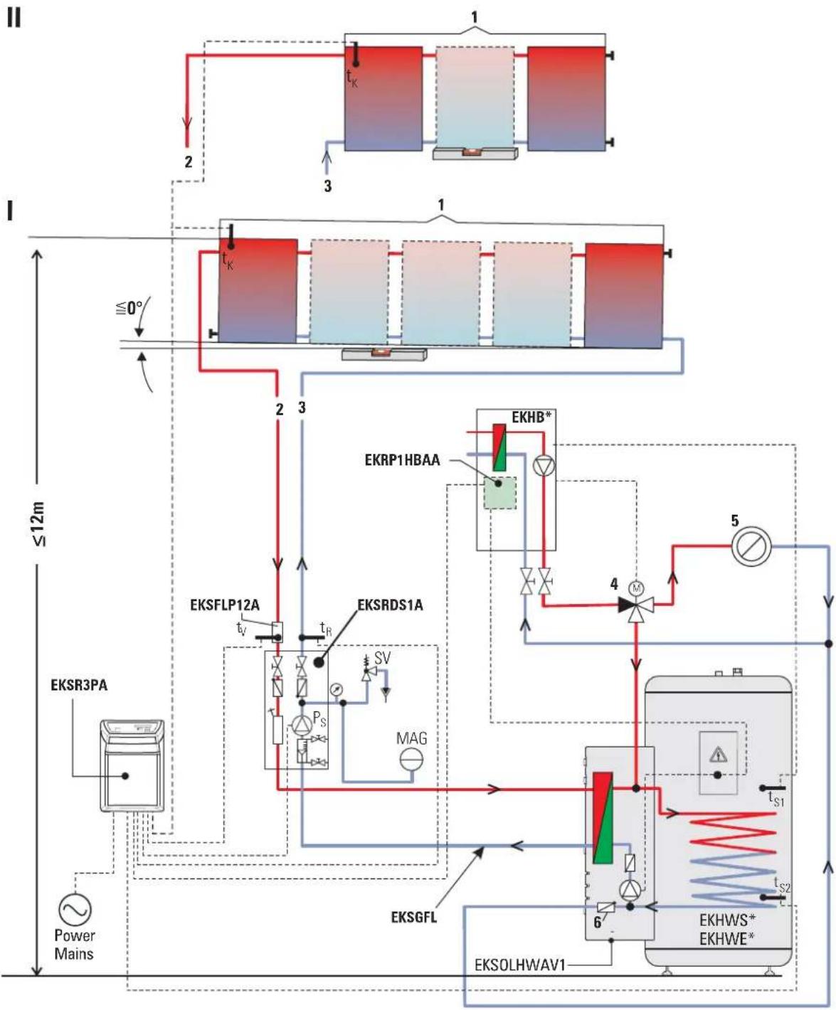
Fig. 2-1 Standard design of a Daikin solar system (Daikin recommends a double-sided connection)
1 Solar panel field
2 Solar feed line (at the top of the solar panels)
3 Solar return line (at the bottom of the solar panels)
4 3-way diverter valve with drive motor
5 Heat distribution
6 Check valve
I Double-sided connection for 2 to 5 solar panels
II Same side connection for max. 3 solar panels (not for in-roof installation)
EKHB* Internal unit of the air-water heat pump
EKHWE*/EKHWS* Hot water storage tank
EKRP1HBAA Solar module
EKSFLP12A FlowSensor (accessory)
EKSGFL Solar system fluid
EKSOLHWAV1 Solar connection kit
EKSRDS1A Pump unit
EKSR3PA Control unit
MAG Diaphragm pressure expansion vessel (building side)
P_S Solar panel circulation pump
SV Pressure relief valve
t_K Solar panel temperature sensor
t_V Solar flow temperature sensor
t_R Solar return flow temperature sensor
t_S1 Storage temperature sensor in air-water heat pump
t_S2 Storage temperature sensor in the controller EKSR3PA
2.2 Brief description
The Daikin solar system is a thermal solar system for supplying hot water.
Operating mode
The high-performance flat solar panels EKSV26P and EKSH26P efficiently convert the sun's radiation into heat. The heat-transfer medium in the solar panel system is a frost-proof water-glycol mixture, and heating water in the tank circulation system.
When the solar panels reach a usable temperature level the fluid in the solar panel circuit EKSGFL is pumped by the pump unit EKSRDS1A and the plate heat exchanger of the solar connection kit EKSOLHWAV1. The circulation pump of the solar connection kit EKSOLHWAV1 (solar panel circulation pump) simultaneously pumps the heating water in the storage tank charging circuit through the plate heat exchanger where it takes up the heat given out by the solar panel circuit and transfers it to the hot water via the storage charging heat exchanger.
Modular design
The system consists of several preassembled modules. Plug-in technology and a high degree of pre-assembly ensure fast and simple installation.
Storage tank
Only the hot water storage tanks EKHWE*/ EKHWS* can be used for the Daikin solar system.

Construction, operating principle, commissioning, and operation of the storage tank are not described in this manual. You will find detailed information on the storage tanks in their respective installation and operating manuals.
Electronic control
The fully electronic control system of the controller EKSR3PA ensures optimum utilisation of the solar heat (hot water generation) and that all safety-relevant aspects are complied with. All parameters needed for trouble-free operation have been preset at factory.
2.3 System components

The Daikin solar system can only be operated with the air-water heat pump EKHBX*, the pump unit EKSRDS1A, the controller EKSR3PA, the solar connection kit EKSOLHWAV1, the water-glycol mixture EKSGFL and the hot water storage tanks EKHWE*/ EKHWS*.
Controller EKSR3PA
Consists of:
- Controller EKSR3PA with storage temperature sensor, return flow temperature sensor with sensor adapter, connection plug solar panel temperature sensor, pump connection and extension cable (P_S) , connection cable for solar priority, connection cable 230V mains connection (3 m)
- Accessory bag (4 fillister screws, 4 plugs, 2 locking screws)
- Documentation
natural_image
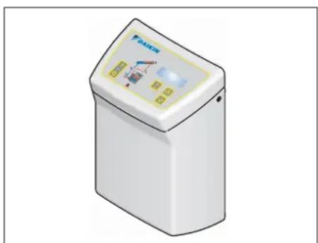
Illustration of a white industrial water heater with control panel and control buttons (no text or symbols)Fig. 2-2 Controller EKSR3PA
Pump unit EKSRDS1A
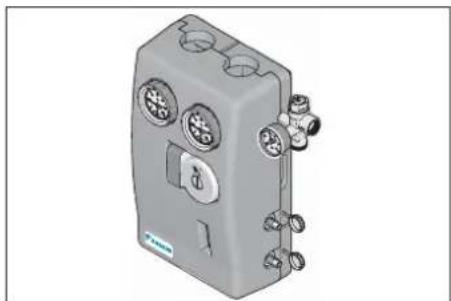
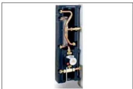
Pump unit including connection fittings for Cu pipe ∅ 22 mm with circulation pump Grundfos Solar 25-65, diameter with 2x KFE cocks, integrated air separator, safety group with pressure gauge, fitting accessories.
natural_image
3D rendering of a gray industrial device with multiple ports and mounting holes (no visible text or symbols)Solar connection kit EKSOLHWAV1
To connect the pump unit EKSRDS1A with the hot water storage tank EKHWE*/EKHWS*.
Consists of:
- Plate heat exchanger
- Circulation pump
- Fitting material
natural_image
Interior view of a black electrical enclosure with visible wiring and components (no text or symbols)Fig. 2-4 Solar connection kit EKSOLHWAV1
Solar module EKRP1HBAA
For connecting the air-water heat pump EKHBH*/ EKHBX* to the Daikin solar system.
Consists of:
- Solar board
- Connection cables
- Fitting material
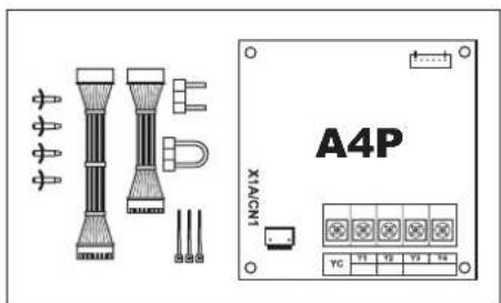
Fig. 2-5 Solar module EKRP1HBAA
2.4 Accessories
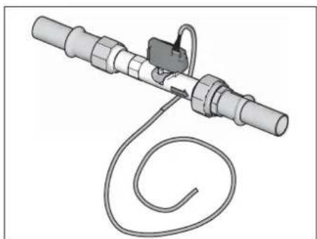
FlowSensor EKSFLP12A
For measuring the flow volume and the feed temperature.
Consists of:
- FlowSensor with pressure and temperature resistant measuring section and pre-assembled pipe adapter
- 3 m cable (ready to plug in).
natural_image
Mechanical device with coiled cable and connector (no text or symbols visible)Fig. 2-6 EKSFLP12A FlowSensor supplied with 3 m cable
3.1 System concepts
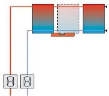
DAIKIN solar systems are usually set up according to one of the following system layouts.
3.1.1 Parallel connection
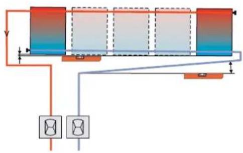
Fig. 3-1 Solar panel connected at both sides (recommended)
natural_image
Pure electrical circuit lines without any symbolsFig. 3-2 Solar panel field with both connections at one end (max. 3 solar panels)
3.1.2 Serial connection
As an alternative to the straightforward parallel connection, as described, the solar panels can, if required, also be mounted in a maximum of three rows one above the other. Solar panels or solar panel fields mounted one above the other must be connected in series (Fig 3-3). One pack of serial connectors for the selected solar system will be required for each additional row of solar panels.
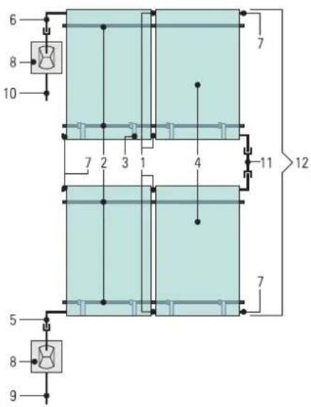
1 Solar panel connector
2 Mounting profile rail
3 Solar panel securing clip
4 Solar panel
5 Return connection solar panel
6 Flow connection solar panel
7 Solar panel connection cap
8 Roof penetration for flow and return flow
9 Solar return line
10 Solar flow line
11 Solar panel serial connector
12 Solar panel field (2x 2 solar panels)
Fig. 3-3 Alternative solar panel arrangement
3.2 Preparatory installation work

WARNING!
Live parts can cause an electric shock on contact and cause life-threatening burns and injuries.
- Before beginning installation and maintenance work, disconnect the electrical components from the power supply (switch off fuse, main switch) and secure against unintentional restart).
- Electrical installations must always be carried out by qualified electrical technicians in conformity with the relevant electrical guidelines and the regulations of the electric utilities company to prevent hazards from damaged electric wiring.
- Comply with the relevant safety at work regulations.

DANGER!
Leaking gas in the immediate proximity of electrical components can cause an explosion.
- The Control and pump unit for solar systems EKSR3PA + EKSRDS1A and electrical components should not be installed in locations where there is a danger of flammable gas escaping.
-
Pay attention to minimum distances from walls and in shafts.
-
Fit solar connection kit EKSOLHWAV1 to hot water storage tank. See installation instructions for solar connection kit.
- Install the solar module EKRP1HBAA in the internal unit of the air-water heat pump EKHBH*/EKHBX*. See installation instructions for solar module.
- Fit solar panel temperature sensor. See installation instructions for solar panels EKSV26P/ EKSH26P.
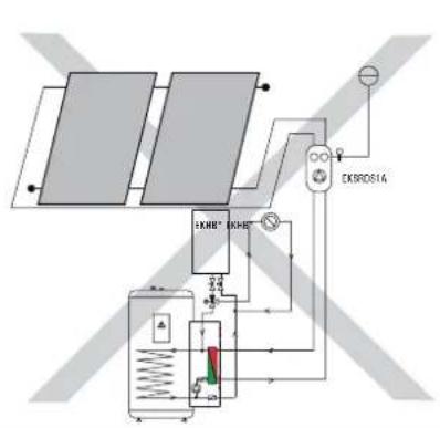
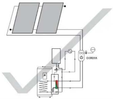
If the circulation in the solar panels comes to a standstill, steam may be formed and may damage the diaphragm expansion vessel (MAG).
- Always install the EKSRDS1A pump unit and the diaphragm expansion vessel (MAG) lower than the solar panels.
flowchart
graph TD
    A["Solar Panel"] --> B["Gas Storage Unit"]
    B --> C["EKRD614 Controller"]
    C --> D["Pressure Control Valve"]
    D --> E["Valve 3.2V"]
    E --> F["Valve 3.5V"]
    F --> G["Valve 3.8V"]
    G --> H["Valve 4.0V"]
    H --> I["Valve 4.2V"]
    I --> J["Valve 4.4V"]
    J --> K["Valve 4.6V"]
    K --> L["Valve 4.8V"]
    L --> M["Valve 5.0V"]
    M --> N["Valve 5.2V"]
    N --> O["Valve 5.4V"]
    O --> P["Valve 5.6V"]
    P --> Q["Valve 5.8V"]
    Q --> R["Valve 6.0V"]
    R --> S["Valve 6.2V"]
    S --> T["Valve 6.4V"]
    T --> U["Valve 6.6V"]
    U --> V["Valve 6.8V"]
    V --> W["Valve 7.0V"]
    W --> X["Valve 7.2V"]
    X --> Y["Valve 7.4V"]
    Y --> Z["Valve 7.6V"]
    Z --> AA["Valve 7.8V"]
    AA --> AB["Valve 8.0V"]
flowchart
graph TD
    A["Solar Panel 1"] --> B["Pressure Gauge"]
    C["Water Inlet"] --> D["Valve"]
    D --> E["Actuator"]
    E --> F["Pressure Gauge"]
    F --> G["Flow Meter"]
    G --> H["Return Line"]
    H --> I["Pressure Gauge"]
    I --> J["Actuator"]
    J --> K["Pressure Gauge"]
    K --> L["Return Line"]
    L --> M["Pressure Gauge"]
    M --> N["Actuator"]
    N --> O["Pressure Gauge"]
    O --> P["Return Line"]

CAUTION!
Danger of scalding if incorrect connection pipes are used.
- The connection pipe between the solar panel array and the hot water storage tank must be made of pressure-resistant metal piping (recommended Cu ∅ 22 mm). Using plastic piping is not allowed.
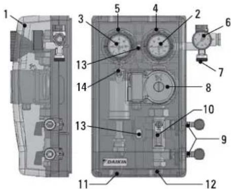
Fig. 3-4 Connections and dimensions pump unit EKSRDS1A
1 Outside cover
2 Temperature gauge on solar return line
3 Temperature gauge on solar feed line
4 Connection of solar return line (∅ 22 mm)
5 Connection of solar feed line (∅ 22 mm)
6 Safety valve with pressure gauge (solar panel circuit)
7 Connection of diaphragm expansion vessel (MAG) (∅ 22 mm)
8 Circulation pump (solar panel circuit)
9 Filling and drainage cock (solar panel circuit)
10 Flowmeter (solar panel circuit)
11 Connection of pump unit feed pipe to solar connection kit EKSOLHWAV1 (Ø 22 mm)
12 Connection of pump return line to solar connection kit EKSOLHWAV1 (∅ 25 mm)
13 Drilled holes for mounting the pump unit on the wall
14 Venting pot
i
General installation instructions
- The pump unit EKSRDS1A should be mounted in such a way that there are no external forces act on the fittings when installed.
- Welding and soldering work on the plant should not cause any overheating. Fit the pump unit EKSRDS1A only after this work has been carried out.
- The pipes must be flushed out thoroughly before installing the pump unit EKSRDS1A to prevent leaks caused by weld spatter, hemp or metallic swarf.
i
Installing the clamping ring bolt:
- Cut off the pipe end at right angles and debur.
- Place swivel nut and clamping ring on the pipe.
- Lightly oil threads.
- Push pipe into the clamping ring bolt to the stop and tighten swivel nut by hand.
-
Tighten swivel nut with open-ended spanner.
-
Remove external cover (1) over the pump unit EKSRDS1A.
- Mount the pump unit EKSRDS1A on the wall in the vicinity of the hot water storage tank.
- Mount the sensor adapter pipe for return flow temperature sensor t _R on the solar return flow on top of the pump unit EKSRDS1A (connection 4).
- Optional: Mount FlowSensor EKSFLP12A on the solar flow at the top on the pump unit EKSRDS1A (connection 5) (see Chapter 3.7).
- Connect the feed and return lines (Cu 0 22 mm) from the solar panel (see Chapter 3.1), at the top of the pump unit EKSRDS1A (connections 4 and 5) in accordance with the system design.
- Install the feed and return lines (Cu 0 22 mm) between the pump unit EKSRDS1A (connections 11 and 12) and the solar connection kit EKSOLHWAV1.
- Connect the diaphragm pressure expansion vessel (MAG) to the pump unit EKSRDS1A (connection 7). Connect the diaphragm expansion vessel in accordance with EN 12828.
- Connect the blow-off line to the safety valve in accordance with EN 12828.
- The blow-off line should be routed so that solar liquid can flow freely into a collection vessel when the safety valve is tripped.
- The blow-off line should be able to be blocked off.
3.4 Controller EKSR3PA
3.4.1 Wall mounting
- Unscrew the screws on both sides of the cover.
- Fold the cover forward and remove downwards.
- Unhook the control system from the housing baseplate.
- Mount the housing baseplate in the vicinity of the pump unit EKSRDS1A on the wall.
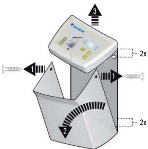
Fig. 3-5 Removing and fixing the control unit
3.4.2 Electrical connections
- Check the power supply voltage at the house junction box ( 230 V, 50 Hz).
- Disconnect the junction box of the domestic installation.
-
Lay the connection cable from the control unit EKSR3PA to the individual components and connect.
-
Power supply (\~230 V, 50 Hz)
- Solar panel temperature sensor t_K (included in the scope of supply of the solar panel components)
- Return flow temperature sensor t_R
– Solar panel circulation pump P _S of the pump unit EKSRDS1A - Board A4P of the solar module EKRP1HBAA
- Storage temperature sensor t S2
- Optional:Flow meter t v (FlowSensor EKSFLP12A)
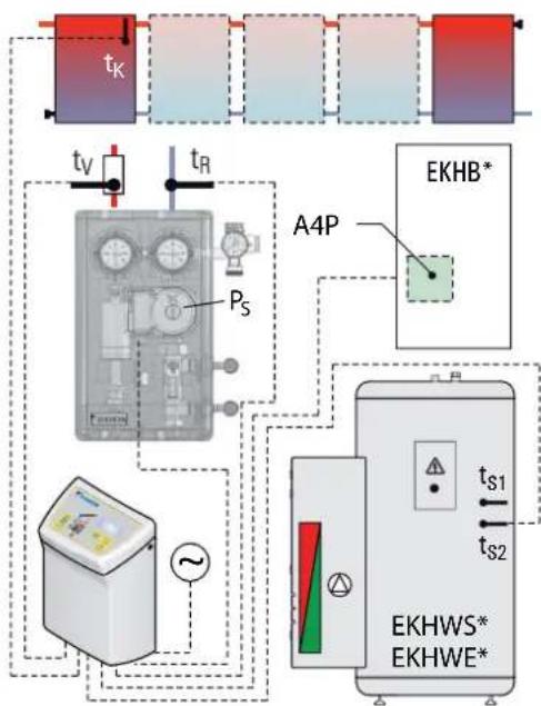
flowchart
graph TD
    A["Power Supply"] --> B["Measurement Device"]
    B --> C["AC Source"]
    C --> D["Ground"]
    D --> E["EKHWS* EKHWE*"]
    E --> F["A4P"]
    F --> G["EKHBS*"]
    style A fill:#f9f,stroke:#333
    style B fill:#ccf,stroke:#333
    style C fill:#cfc,stroke:#333
    style D fill:#fcc,stroke:#333
    style E fill:#cff,stroke:#333
    style F fill:#ffc,stroke:#333
    style G fill:#fcf,stroke:#333
Fig. 3-6 Electric cabling EKSR3PA
- Fix the cable supplied to the back of the control system using the edge connectors. The plugs are coded to prevent mixing them up. The configuration of connections is shown on the lid of the control system.
- Connect solar panel temperature sensor line (integrated in the connection cable) to the terminals in the plug and connect the plug on the edge of the board of the control system, to position TK (2-pole, see Fig 3-10).
- Optional: Connect the FlowSensor EKSFLP12A plug (see Chapter 3.7).
- All the cables are routed through the labyrinth to ensure there is stress relief.

natural_image
Close-up of hands using a screwdriver to adjust small components (no text or symbols visible)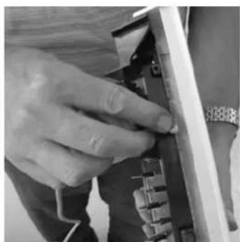
natural_image
Close-up of a hand adjusting a small electronic component (no visible text or symbols)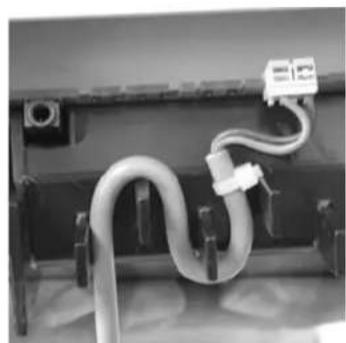
natural_image
Close-up of a coiled white hose with attached cable and connector (no visible text or symbols)Fig. 3-7 Steps 4+5 Fig. 3-8 Steps 4+5 Fig. 3-9 Step 7
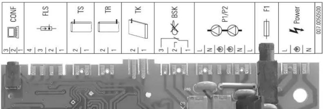
Fig. 3-10 Connection assignment
CONF Programming socket for software updates
FLS FlowSensor EKSFLP12A (accessory)
TR Return flow temperature sensor
TK Solar panel temperature sensor
P1/P2 Solar panel circulation
pump P_S
F1 Fuse
Power Power supply
TS Storage temperature sensor t S2
BSK Connection cable for solar priority
natural_image
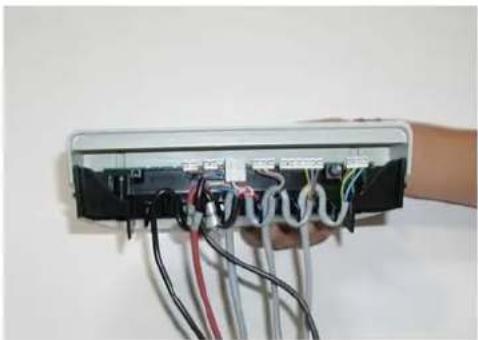
Hand holding a device with multiple wires and connectors, no visible text or symbolsFig. 3-11 Basic cabling: tank, solar panel sensor, pump and power feed
natural_image
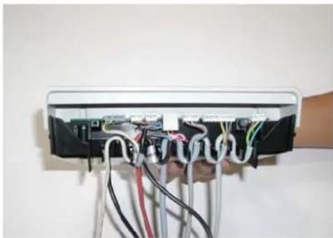
Hand holding a black electronic device with multiple wires and connectors, mounted on a stand (no visible text or symbols)Fig. 3-12 Extended cabling additionally with FlowSensor
- Place control systems into the housing baseplate from above.
- Hook the cover into the bottom of the housing baseplate and click into the control system at the top.
- Screw cover on both sides to the control system housing again with countersunk screws.
- Lay the cable to the components.
- Connect the cable for solar priority (points 1+4 in the Figures 3-13 and 3-14) to the board A4P of the solar module EKRP1HBAA and the connection X2M of the internal unit of the air-water heat pump.
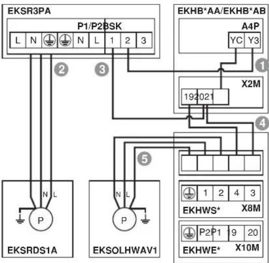
flowchart
graph TD
    A["EPKR3PA"] -->|L N N L 1 2 3| B["192021"]
    C["EPKRDS1A"] -->|N L P| D["192021"]
    E["EPKSHWAV1"] -->|N L P| F["192021"]
    G["AKSHBSK"] -->|P1/P2 BSK| H["A4P"]
    I["AKSHBSK"] -->|YC Y3| J["X2M"]
    K["AKSHBSK"] -->|P2P1 9 20 X8M| L["X8M"]
    M["AKSHBSK"] -->|YC Y3| N["X2M"]
Fig. 3-13 Connection cable for solar priority on EKHBH/X_AA and EKHBH/X_AB
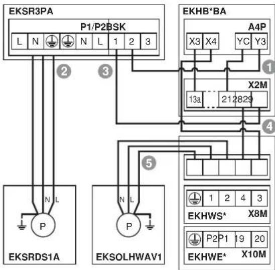
flowchart
graph TD
    A["EPKR3PA"] -->|L N N L 1 2 3| B["EPKRBSK"]
    C["EPKRBSK"] -->|N L P| D["EPKRDS1A"]
    E["EPKRBSK"] -->|N L P| F["EPKOLHWAV1"]
    G["EPKHBA"] -->|X3 X4 YC Y3| H["A4P"]
    H --> I["X2M"]
    I --> J["13a 212829"]
    J --> K["1 2 4 3"]
    K --> L["1 2 4 3"]
    L --> M["EKHWS* X8M"]
    M --> N["P2 P1 19 20"]
    N --> O["EKHWE* X10M"]
Fig. 3-14 Connection cable for solar priority on EKHBH/X_BA
3.5 Pump unit EKSRDS1A - electrical connection
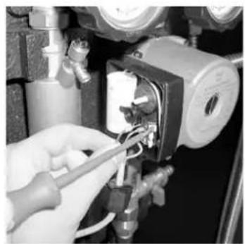
- Remove cover on switch casing of solar panel circulation pump.
- Connect control line to solar panel circulation pump.
- Install cover on switch casing of solar panel circulation pump.
- Lay control line in casing of EKSRDS1A pump unit.
- Replace the external cover (1) on the pump unit EKSRDS1A.
natural_image
Close-up of a hand using a tool to adjust or install a mechanical component (no visible text or symbols)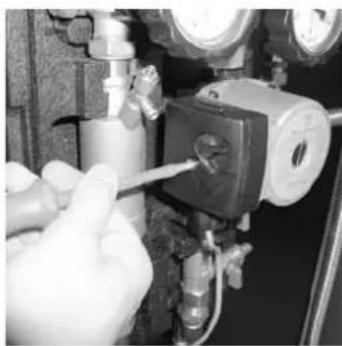
natural_image
Close-up of hands using a tool to adjust or install a pressure pump component (no visible text or symbols)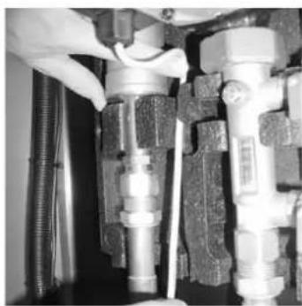
natural_image
Close-up of hands adjusting a mechanical valve assembly with tubing (no visible text or symbols)Fig. 3-15 Work step 2 Fig. 3-16 Work step 3 Fig. 3-17 Work step 4
3.6 Storage temperature sensor
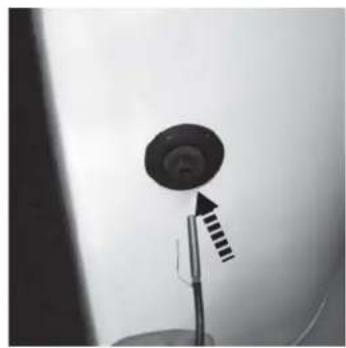
- Insert the storage temperature sensor t_S2 (included in supply) into the bottom connection on the hot water storage tank.
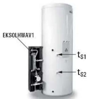
Fig. 3-18 Position storage temperature sensor
natural_image
Close-up of a black circular object mounted on a stand with a striped arrow pointing upward (no text or symbols visible)Fig. 3-19 Installation storage temperature sensor t_S2
3.7 FlowSensor (optional)
i
- During installation be aware of the flow direction of the measurement instruments.
- The FlowSensor and the measuring section must not be overheated by welding and soldering work on the plant. Only fit the measuring section after this work.
- Tighten the screwed fittings after final installation of the measuring section.
The FlowSensor EKSFLP12A (Page 9, Fig 2-6), available as an accessory, is a measurement instrument that records the flow volume in the solar panels and the feed temperature. The measurement range of the FlowSensor EKSFLP12A is between 0 and 12 l/min (flow volume) and 0 to 120 °C (feed temperature).
The measured values are shown on the control unit EKSR3PA display. The control system EKSR3PA automatically sets the appropriate flow rate when the system is in operation by regulating the speed of the solar panel circulation pump.
- Slide the swivel nut (2) and the cutting ring (1) over the pipe adapter (3) at the outlet of the FlowSensor (4).
- Push the pre-assembled FlowSensor (4) onto the flow connection of the control unit EKSR3PA and tighten the swivel nut (2).
- Lay the FlowSensor cable (5) between FlowSensor (4) and the control unit EKSR3PA.
- Connect FlowSensor cable (5) to FlowSensor (4) and to the control system printed circuit board edge at position FLS (4-pin, see Fig 3-10).
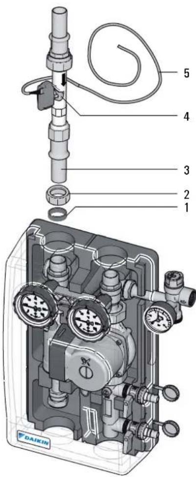
Fig. 3-20 Installation FlowSensor EKSFLP12A
4.1 Initial start-up

WARNING!
The solar system cannot be started until all hydraulic and electrical connections have been completed.
An incorrect start-up will adversely affect the function and may damage the complete system. Installation and start-up must therefore must conducted by DAIKIN-authorised and trained heating experts.
4.1.1 Filling solar panel circuit

CAUTION!
Danger of scalding by hot solar fluid and escaping steam.
- Only fill the solar panel circuit when there is no strong direct sunlight or only if the solar panels are covered up.

WARNING!
If the heat transfer medium is mixed with other substances, frost and corrosion protection may be reduced. This may damage system components.
- Conduct all work on the components of the solar system only with the solar panels covered.
- The solar system should only be flushed and filled with the included heat transfer medium EKSGFL.
- Mixing of the heat transfer medium with other materials is not permitted.

WARNING!
If heat transfer media containing glycol are exposed to temperatures above 170 °C over an extended period, they will decompose or form silt. This may reduce the frost protection, affect the output of the solar system and damage components of the system.
- Start operation of the solar system immediately after filling it.
- Drain the system if it is to be out of operation over an extended period.
- Replace the heat transfer medium in the system before start-up after extended downtime.
| MAG initial pressure | System fill pressure | Maximum system pressure |
| p_v = 0.1 × h_stat + 0.5 bar p | _0 = p_v + 0.3 bar p | _e <= 0.9 × p_sv |
p_e Maximum permissible system pressure p_v (hot) in bar
p_sv Operating pressure of safety valve p_0 (>3 bar)
MAG initial pressure in bar
(at least 1.2 bar)
System filling pressure (cold) in bar
h_stat Static height in m between centre of MAG and the highest point of the system.
Tab. 4-1 Calculating pressures for start-up
-
Check that all threaded fasteners are tight.
-
Calculate the required initial pressure for the diaphragm expansion vessel (MAG) with the system unpressurised, check it and adjust if necessary (see MAG initial pressure Tab. 4-1).
-
Open ball cock ball valves of feed and return flow at the EKSRDS1A pump unit.
-
Set the blocking of the flow meter (Item 10, Fig 3-4) to the filling position (slot horizontal).
flowchart
graph TD
    A["Solar Panel"] --> B["EKHB*"]
    B --> C["Valve"]
    C --> D["Pressure Gauge"]
    D --> E["Valve"]
    E --> F["Control Valve"]
    F --> G["Water Tank"]
    H["EKSRDS1A"] --> I["Valve"]
    I --> J["Control Valve"]
    J --> K["Valve"]
    K --> L["Water Tank"]
    M["1"] --> N["3"]
    N --> O["2"]
    O --> P["Flow Line"]
    P --> Q["End"]
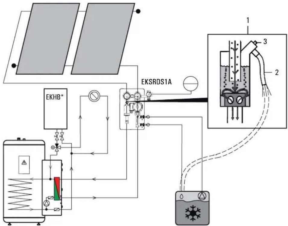
Fig.4-1 Filling and venting the solar panel circuit
- Connect filling/flushing pump by hose to the upper KFE cock (see also Item 9, Fig 3-4) of the pump unit EKSRDS1A.
- Connect the return hose to the lower KFE cock (see also Item 9, Fig 3-4) of the pump unit EKSRDS1A and direct to the filling container from which the solar fluid EKSGFL is to be filled into the solar panel circuit.
- Open KFE cocks and start filling/flushing pump.
- Fill and flush the solar panel circuit until the solar fluid flows back into the filling container cleanly and without any bubbles
- The pressure at the pressure gauge of the pump unit EKSRDS1A must not exceed the maximum permissible system pressure p_B (Tab. 4-1).
- Close the lower KFE cock.
- Increase the solar panel circuit pressure to at least 0.3 bar above the pressure set at the diaphragm expansion vessel (MAG) (see system fill pressure Tab. 4-1).
- Close the upper KFE cock.
- Vent the system as follows :
- Direct the venting hose of the venting pot into a suitable collection vessel.
- Open valve (Item 3, Fig 4-1) of the venting pot (Item 1, Fig 4-1).
→ Displaced air escapes from the venting pot. -
Close the valve as soon as solar fluid comes out of the venting pot.
-
Check the system pressure on the pressure gauge of the pump unit EKSRDS1A again.
-
The system pressure must not drop over a period of 1/2 hour.
- If the pressure drops, check the solar panel circuit and connections for leaks and repair if necessary.
- Vent solar panel circuit again (residual air in system).
-
If necessary, correct the system pressure by adding solar fluid (see working step 4 onwards).
-
Separate the filling/flushing pump with hoses from the pump unit EKSRDS1A.
-
Open the blocking of the flow meter completely (slot vertical).
4.1.2 Regulate the flow rate on the solar panel circuit
- Connect the mains line of the control unit EKSR3PA to the plug socket of the domestic supply ( 230 V, 50 Hz) and provide power supply.
- Switch on the control unit EKSR3PA (initialisation phase starts).
- After the initialisation phase (temperature display), start the system by pressing the two arrow keys simultaneously (manual operation).
→ The pump then runs up to its full output.

The pumps are only switched on if the temperature of the solar panels is higher than the minimum value coupled to the minimum temperature of the storage tank (see chapter 5.2.10) and lower than the specified approved maximum temperature.
If there is a longer period between step 5 and 8, the temperature of the solar panels may be outside the approved range. If T_K > T_Kzul it is not necessary to switch to manual operation.
- Close the regulating valve (closing the flow meter) completely. The system is now under the maximum possible operating pressure.
- Look for leaks by carrying out a visual examination of all connection points in the house and on the roof. Repair any leaks found.
- Finish heat insulation at connection points.
- Adjust flow depending on the number of solar panels. For reference values for the setting see Tab. 4-2.
| Number of solar panels | Set flow rate in l/min on solar panel circuit | Set flow rate in l/h on solar panel circuit |
| 2 3.6 to 4 | 8 220 to 290 | |
| 3 5.4 to 7 | 2 330 to 435 | |
| 4 7.2 to 9 | 6 435 to 580 | |
| 5 9 to 12 | 540 to 720 |
Tab. 4-2 Setting the flowrate on the flow meter
8. Switch the control unit EKSR3PA off.
9. Instructing the user/owner

The flow of the solar panel circuit can be checked and set at the flow display of the DAIKIN pump unit EKSRDS1A (settings see Tab. 4-2).
When using the FlowSensors EKSFLP12A completely open the regulating valve.
→ The optimum flow rate is automatically adjusted by regulating the speed of the pump.
→ At the same time the control system performs an output measurement and energy balance.
4.1.3 Filling the storage tank and heating circuit
- Filling the hot water storage tank; see the associated installation and operating instructions.
- Filling the heating system and venting; see the associated installation and operating instructions.
4.2 Taking out of service
4.2.1 Temporary shutdown

CAUTION!
A heating system which is shut down can freeze in the event of frost and may suffer damage.
- Drain the heating system that is shut down if there is danger of frost.
If solar heating support is not required for water heating for an extended period, the solar system can be switched off temporarily at the mains switch of the EKSR3PA control unit.
In the event of frost danger you must:
- start the solar system in operation
or
- suitable antifreeze measures must be applied to the connected heating system and hot water storage tank (e.g. draining).

If there is a danger of frost for just a few days, the unit's excellent heat insulation means that the insulated tank does not have to be drained, provided that the storage tank temperature is monitored regularly and does not fall below +3°C. This does not, however, provide any protection against frost for the connected heat distribution system!
4.2.2 Final shutdown
- Switch on the EKSR3PA + EKSRDS1A control and pump unit again (see Chapter 4.2.1 "Temporary shutdown").
- Disconnect the EKSR3PA + EKSRDS1A control and pump unit from all electrical and water connections.
- Dismantle the EKSR3PA + EKSRDS1A control and pump unit in accordance with the assembly instructions (Chapter 3 "Montage") in reverse order.
- Dispose of the EKSR3PA + EKSRDS1A control and pump unit correctly.
Recommendations for disposal

Thanks to the environmentally friendly design of the solar system, DAIKIN has complied with requirements for environmentally sound disposal. During the disposal process, the only waste created is that which can be used for material or thermal recycling.
The materials that are suitable for recycling can be separated so that they are unmixed.

This marking on the product indicates that electrical and electronic products must not be disposed of in unsorted household waste.
Proper disposal in compliance with the applicable national regulations of the country of use is the responsibility of the user/owner.
- Dismantling the system, handling refrigerant, oil and other parts may only be carried out by a qualified technician.
- Disposal only via an organisation specialised in reutilisation, recycling and recovery.
Further information can be obtained from the installation company or from the responsible local authority.
5.1 Operating and display components
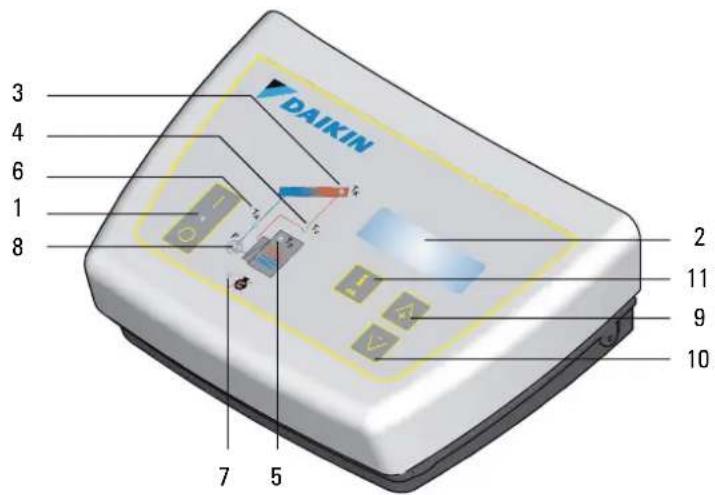
Fig. 5-1 Operating and display elements of the EKSR3PA control system
1 Main switch with indicator light
2 Display of temperature and parameters (energy-saving function: display lighting switches off automatically 10 min after the last button press)
3 Indicator for solar panel display
4 Indicator for solar feed temperature and flow rate display
(EKSFLP12A)
5 Indicator for storage tank temperature display
6 Indicator for solar return temperature display
7 Operating condition for BSK-contact (solar priority) - "lights up" when contact is closed (signal for air-water heat pump that solar heat is available)
8 Operating status indicator for P S solar panel circulation pump (lights when pump is operating)
9 Push arrow key up to switch the temperature or parameter display in the direction of the arrow or to increase the parameter setting
10 Push arrow key down to switch the temperature or parameter display in the direction of the arrow or to reduce parameter settings
11 Info button to open the information level (displays of measurement values, maximum values and calculated values) and OK pushbutton to confirm and save settings in the settings menu
5.2 Operation of control systems
| i | Because of continual improvements for optimum use of the EKSR3PA + EKSRDS1A control and pump unit, the solar control system is fitted with an update function. Therefore, some functions described in this chapter are applicable to specific software versions only. These functions are indicated separately by symbols.Software updates to the solar control system must be done by DAIKIN service technicians only. |
| i | The DAIKIN solar system is operated fully automatically throughout the year. The speed of the pump drive is controlled by the solar control system when the FlowSensor EKSFLP12A is connected. The operating and display components are shown in Fig 5-1.The power switch completely disconnects the solar control system from the mains voltage. Switching on the power switch requires greater pressure on the button than pressing the operating buttons. |
5.2.1 Pump operation
Criteria for switching on:
- Pump operation depends on the continuously measured temperature difference between the solar panel and the storage tank temperature and a comparison with the set value of the parameter "Delta T on".
- The solar panel circulation pump P S switches on when the temperature difference (=T K - T _s ) exceeds the value set in the parameter "Delta T on" (e.g. storage tank temperature equals 40 °C and "Delta T on" is equal to 15 K; solar panel temperature >55 °C).
i
- After expiry of the time set in parameter "Time UB", the controller switches to operation mode and monitors, in sequence:
a) With connected FlowSensor EKSFLP12A: The temperature difference between solar feed and return flow temperature (" T_V - " T_R ").
b) Without FlowSensor: The temperature difference between solar panel and return flow temperature (" T_K - " T_R ").
- It is only with connected FlowSensor that the pump output is regulated in dependence of the temperature difference between the solar feed and return flow temperature.
- With a short delay ("Time PsE") after switching on the solar circulation pump P _S the contact for solar priority switches and transfers this signal to the air-water heat pump. The incorporated electronics decides whether the pump fitted in the connection kit EKSOLHWAV1 is activated.
Criteria for switching off:
- The pumps are switched off if the temperature difference falls below the "Delta T off" parameter value.
a) With connected FlowSensor EKSFLP12A: The temperature difference between solar feed and return flow temperature (" T_V - " T_R ). e.g. return flow temperature = 45 °C and "Delta T off" = 2 K; Solaris feed temperature < 47 °C.
b) Without FlowSensor: The temperature difference between solar panel and return flow temperature (" T_K " - "T _R ").
- If the maximum storage tank temperature set in parameter "T S max" is reached (T S indicator flashes). In this case the pumps can only be started again if the storage tank temperature has fallen by more than 2 K.
- If the maximum solar panel temperature set in parameter "T k zul" is reached (T k indicator flashes). In this case the pumps can only be started again if the solar panel temperature has fallen by more than 2 K.
i
If a FlowSensor is not installed or is faulty, the solar panel circuit pump runs constantly at the set output level (without speed control). The pumps are regulated exclusively by the temperature difference between the solar panel and solar return flow temperature.
other
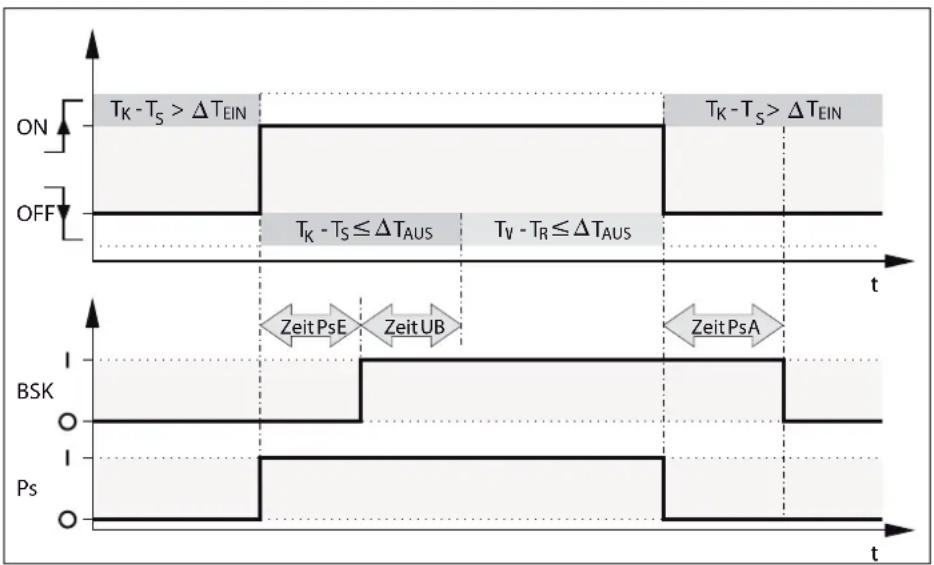
| Signal | Time Segment | Pulse Description | |--------|--------------|----------------------------------------| | ON | On | T_k - T_s > ΔT_EIN | | OFF | Off | T_k - T_s ≤ ΔT_AUS | | BSK | BSK | Zeit PsE, Zeit UB, Zeit PsA | | Ps | Ps | Ps |Fig. 5-2 Start and stop sequence (with FlowSensor EKSFLP12A)
T_ON ( T_EIN) Cut-in temperature difference
T_OFF( T_Aus) Cut-out temperature difference
PS Solar panel circulation pump
BSK Contact for solar priority
t T i
T_K Solar panel temperature
T_R Return flow temperature
T_V Flow temperature
Time PsA (Zeit PsA ) Switch-off delay BSK
Time PSE (Zeit PSE ) Switch-on delay BSK
Time UB (Zeit UB ) Reverse condition delay time
1 Switch-on delay BSK:
For maximum use of the heat the solar panel circuit is started before circulating the storage tank circuit. The preheated plate heat exchanger can heat immediately with the time-offset start of the tank circulation pump. e
2 Switch-off delay BSK:
To prevent temperatures >100^ in the plate heat exchanger after the solar panel circulation pump switches off, for the time _PSA set in the parameters.
i
The storage tank circulation pump is in the solar connection set EKSOLHWAV1. It is switched on with the air-water heat pump when the contact BSK is closed and the solar priority is present (see Installation and Operating Instructions EKSOLHWAV1).
5.2.2 Contact for Solar Priority (BSK)
System considerations mean that hot water cannot be heated simultaneously with the solar system and the air-water heat pump.
For this reason, the contact for solar priority (BSK) is closed by the control system EKSR3PA when the solar panel circulation pump P_S is switched on. This transfers the signal that the solar system is active to the air-water heat pump via the cable connected to the printed circuit board A4P of the solar module EKRP1HBAA. The LED for the BSK contact (Item 7, Fig 5-1) lights up.
If the control system of the air-water heat pump is set to hot water generation with solar priority, the storage tank circuit pump in the solar connection kit EKSOLHWAV1 is switched on by this control system. At the same time, the hot water generation is blocked by the air-water heat pump.
5.2.3 Switch-on lock-out function
The switch-on lock-out function prevents:
- reactivation if the solar system has been automatically shutdown because the set maximum storage tank temperature "T _S max" has been reached.
- pump operation if the solar panel temperature exceeds the value set by the heating expert with the parameter "T K zul". Under sustained solar radiation temperatures markedly in excess of 100 °C may occur at the solar panels after switching off the solar circuit pump. If the storage tank temperature falls below the release temperature ("T S max" - 2 K) in this situation (e.g. by removal of hot water), the solar circuit pump is switched on again when the cut-in switch protection temperature at the solar panels set with parameter "T K zul" falls by 2 K. The T K indicator flashes.
The function blocking time "Time SP" makes it possible, that, in the event of a switch-off condition caused by the flow sensor (FlowSensor), only after the blocking time (0 – 600 s) set in the solar control system has expired can the pumps be released again.
Therefore:
– cycling of the system can be minimised.
- the solar panels can reach a higher temperature.
– the feed temperature during filling the system does not fall below the cut-out condition and the system regulates itself faster.
5.2.4 Manual operation
The system can started manually with the time set in the parameter "H/A" for start-up and testing only. All control functions are disabled and the solar circuit pump runs continuously at the specified output independently of the system temperatures.
- Pressing (>1 s) both arrow keys simultaneously activates or deactivates manual operation.

CAUTION!
Uncontrolled manual operation can lead to vapour pressure pulses, heat losses and excessively high storage tank temperatures.
To prevent vapour pressure pulses:
- the solar panel temperature must be T_K < T_K zul. Manual operation is blocked if T_K > T_K zul and can only be started after sufficient cooling of the solar panels.
5.2.5 Solar FlowSensor EKSFLP12A
The optional FlowSensor is used to measure the flow "V" and the feed temperature "Tv".
If a sensor is connected and activated:
- the measurement values "V" and "T v" are displayed.
– the control systems operate after the filling process with the actual system temperature difference of feed and return temperature.
- if the speed of the solar circuit pump is regulated.
If the system has detected the FlowSensor once, a fault signal is shown if the sensor is faulty or disconnected (see section 6.1).
The system now operates in emergency mode without a FlowSensor.
If the control systems detect a FlowSensor after a new installation or a reset by a technician, the value "12" in parameter "FLS active" is automatically set. It is only necessary to check and, if necessary, adjust the correct parameter value for the specific FlowSensor (see Tab. 5-1). The Flow Sensor can be disabled by input of the parameter value "0".
| FlowSensor Parameter value"FLS active" | Minimum flowstart phase "V1" in l/min | Minimum flowoperating phase "V2" in l/min |
| 1.0 12 1.5 1.0 |
Tab. 5-1 Overview flow rates FlowSensor
If the FlowSensor is disabled by the heating expert, a fault signal is not shown. The control system now operates without the measured value for the flow. The feed temperature " T_V " is set to be equal to the solar panel temperature " T_K ".
5.2.6 Output calculation, maximum values and yield count

Balancing and calculating system operating data (e.g. solar heat yield) does not replace official calibration of the heat meter. The values must not be used for distribution of heat costs or similar official balances.
If a FlowSensor is connected, the system operating data is calculated and balanced, such as the current heat output and the solar heat yield. The maximum and calculated values can be shown on the display (see chapter 5.3). Values greater than "0" that have not been deleted will continue to be displayed even after removal or deactivation of the FlowSensors (without further updates).
5.2.7 Speed regulation of the solar circuit pump P s

The automatic speed control of the pump unit EKSRDS1A will only operate if a FlowSensor is integrated into the system. Otherwise the solar circuit pump will operate at 100%.
After completed start sequence, the solar control system initiates:
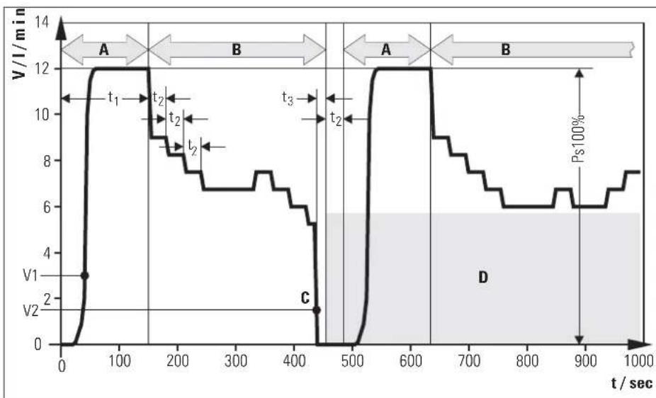
- Stepwise output reduction of P_S until the calculated nominal spread "DT" maintains the setpoint value corresponding to Fig 5-3, or until it falls below the minimum flow V2 (Fig 5-4).
- The switch to the next pump stage is implemented after a safety time "t 2" (Fig 5-4).
If the pump output is too small, the flow in the solar circuit can fall below the threshold value required to provide reliable data evaluation. If the flow falls below this minimum value "V2"(Fig 5-4) for at least 10 s, the control system detects a flow breakdown which could also be caused by, e.g. a leak or the pump coming to a standstill. The last valid output level is stored as the minimum pump output. Lower pump output stages are blocked.
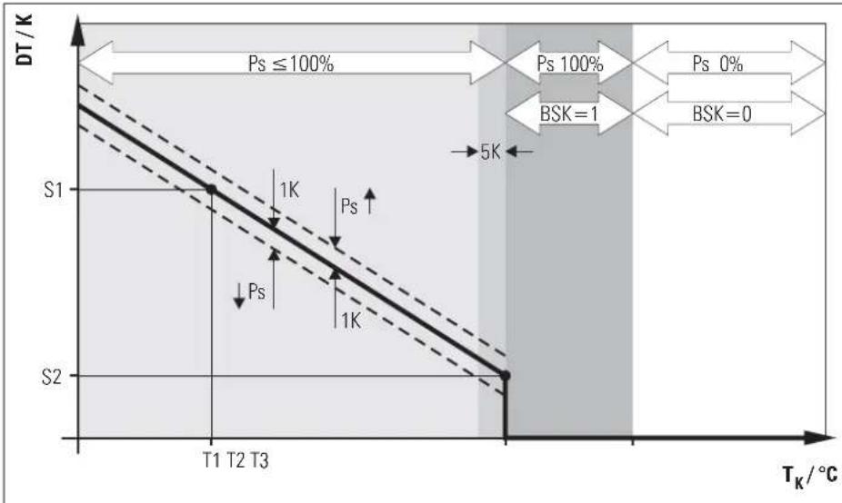
The temperature-dependent output control of P_S is between the calculated minimum and maximum output. The spread of " T_V " and " T_R " is continuously measured and compared with the nominal spread. If the temperature spread between " T_V " and " T_R " is too great, the pump output of P_S (max. 10 stages) and therefore the flow through the solar panels is increased until the nominal spread is reached. If the spread is too low, the pump output is reduced. The actual pump output of P_S while it is running is displayed as a percentage in the "Flow" indicator beside the measured flow value. A typical operating sequence of a modulating solar system is shown in Fig 5-3.
line
| T_K / °C | DT / K | | -------- | ------ | | T1 | 1K | | T2 | 1K | | T3 | 1K | | >T2 | 5K |DT Nominal spread (calculated for the working point)
S1 Upper nominal spread ("spread 1")
S2 Tower nominal spread ("spread 2")
T_K Solar panel temperature
T1 Minimum temperature of storage tank ("T R min")
T2 Booster temperature ("TK max")
T3 Cut-in protection temperature ("TK zul")
- Nominal spread
--- Switching limits for pump modulation
Fig. 5-3 Temperature difference-dependent pump output control
line
| t/sec | V/1/min | |-------|---------| | 0 | 0 | | 50 | 3 | | 100 | 12 | | 150 | 12 | | 200 | 9 | | 250 | 8 | | 300 | 7 | | 350 | 7 | | 400 | 6 | | 450 | 0 | | 500 | 0 | | 550 | 12 | | 600 | 12 | | 650 | 9 | | 700 | 8 | | 750 | 7 | | 800 | 6 | | 850 | 6 | | 900 | 6 | | 950 | 7 | | 1000 | 7 |A Start phase
B Operating phase (modulation)
C Flow stall
D Low pump output stages are automatically blocked after flow stall
V Flow in solar panel circuit
V1 Minimum flow in start phase ("VS min")
V2 Minimum flow in operating phase ("S-flow")
t Time
t1 Start run time of the solar panel circuit pump at 100% ("Time PsE")
t2 Stabilisation time ("S-time")
t3 Stall detection time (10 s)
Fig. 5-4 Example of modulation operation with blockage of the lower pump stages in systems with FlowSensor when the minimum flow rate is not achieved
5.2.8 Global reset function
The device responds to a global reset with a new start (self-test), all parameters are reset to the factory settings and all blocked pump output stages are released. Reset by:
- pressing OK and arrow keys simultaneously.
5.2.9 Frost protection function
As soon as the control system records a solar panel temperature " T_K " below " T_R min" (factory-defined frost protection return temperature), the frost protection function is activated. It remains activated for 24 h after the limit temperature has been exceeded.
While frost protection is active a star icon is shown in the standard temperature display.
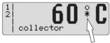
Fig. 5-5 Operating display when frost protection is active
The solar system only starts up with active frost protection if the switch-on condition is fulfilled and the solar panel temperature " T_K " exceeds the value " T_K save" (factory setting 40 °C). The BSK contact for solar priority is then activated at the same time as the solar panel circuit pump. This prevents the plate heat exchanger from freezing at outside temperatures below 0°C.
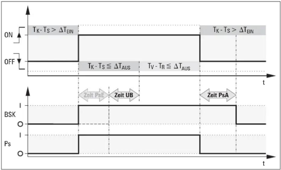
Fig. 5-6 Start and stop sequence (with FlowSensor EKSFLP12A) with frost protection function
BSK Cable for solar priority
P_S Solar panel circulation pump
t T i m e
Time PSA (Zeit PSA ) Switch-off delay BSK
Time PSE (Zeit PSE ) Switch-on delay BSK
Time UB (Zeit UB ) Reverse condition delay time
5.2.10 Leak protection function
If no minimum flow start phase "V1" in accordance with Tab. 5-1 is detected at the FlowSensor after switching on or releasing pump P_S in maximum cut-in delay for tank circulation pump BSK "Time PsE", the following are possible:
- a fault in the FlowSensors or
- vapour formation in the solar circuit or
- a leak in the solar circuit.
To prevent the solar fluid from being pumped out of the system if there is a leak, the pump P_S is shutdown for 2 h and the fault signal "W" is shown in the left column of the display.
After three fault signals in succession the pump P_S switches off permanently and the fault signal "F" is shown in the left column of the display.
- Replace faulty sensor or eliminate leak.
- Start system manually.
5.3 Setting and menu operation
Tab. 5-2 shows an overview of the available measuring points and the associated display formats. Tab. 5-3 summarises the views of the calculated parameters.
| Measuring point | Designation Measurement range | Resolution ensor | ||
| Display | ||||
| T_{K} | Solar panel temperature -30 to 250 °C 1 K PT 1000 temperature sensor | |||
| T_{R} | Return flow temperature 0 to 100 °C 1 K PTC temperature sensor | |||
| T_{S} | Storage tank temperature 0 to 100 °C 1 K PTC temperature sensor | |||
| T_{V}$ | Flow temperature | 0 to 100 °C | 1 K | FlowSensor with voltage output 0.5 to 3.5 V |
| V | Flow | 0.0 to 12.0 l/min | 0.1 l/min | FlowSensor 12 with voltage output 0.5 to 3.5 V |
Tab. 5-2 Overview of measuring points
| Individual | Designation | Value range | Resolution | Comment |
| TK max | Maximum measured solar panel temperature | -30 to 250 °C | 1 K | Maximum measured solar panel temperature since reset |
| TK min | Minimum measured solar panel temperature | -30 to 250 °C | 1 K | Maximum measured solar panel temperature since reset |
| V max | Maximum flow | 0.0 to 12.0 l/min | 0.1 l/min | Maximum flow rate achieved during filling 1) |
| PS | Peak output | 0.0 to 99.9 kW | 0.1 kW | Maximum value from 5 min output average 1) |
| HP (15h) | Daily peak output | 0.0 to 99.9 kW | 0.1 kW | Maximum value of the peak power within the last 15 h 1) |
| W (15h) | Daily heat yield | 0.0 to 999.9 kW | 0.1 kWh | Heat yield obtained from the momentary output within the last 15 h 1) |
| W | Total heat yield | 0.0 to 9999.9 kWh or 10.000 to 99.999 kWh | 0.1 kWh0.0001 MWh | Total solar heat yield obtained from the momentary output 1) |
| P | Instantaneous output | 0.0 to 99.9 kW | 0.1 kW | Average of the last minute 1) |
| DT | Nominal spread | 1 to 15 K | 1 K | Nominal temperature difference T_V-T_R at modulation operation (calculated) 1) |
| PS | Current output stage of the solar panel circuit pump | 0 to 100% | 1% | 1) |
| Stage min | Smallest released output stage of the solar panel circuit pump | 0 to 10;0 to 100% | 1; 1% | Only available with technician access (see Fig 5-9) 1) |
| P1 on | Running time of the solar panel circuit pump | 0 to 99999h | 1 h | Only available with technician access (see Fig 5-9) 1) |
Tab. 5-3 Maximum values and calculated values - ^1) only with connected FlowSensor EKSFLP12A
5.3.1 Start display
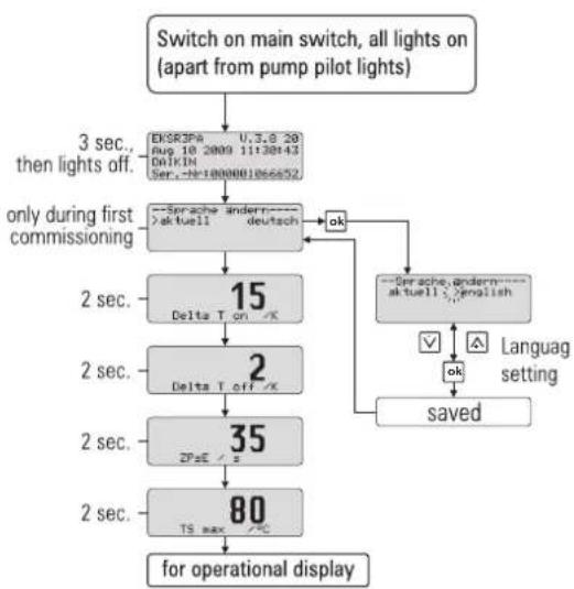
After switching on, the solar control system carries out a self test where the display elements are switched on individually and the setting parameters of the user level are displayed. The following test steps are run and displayed in succession for approx. 2 s (Fig 5-7):
- Immediately after switch-on the start screen appears showing the installed software version and the serial number of the unit.
- At the initial start-up the user is prompted to select the display language.
- The function of the pump and the status indicator can only be checked manually for security reasons (see chapter 5.2.4).
5.3.2 Operating display
The operating display shows system temperatures, maximum and calculated values. After the start display, the solar control system is automatically in operating display mode, an operating value is displayed and the associated indicator lights up.
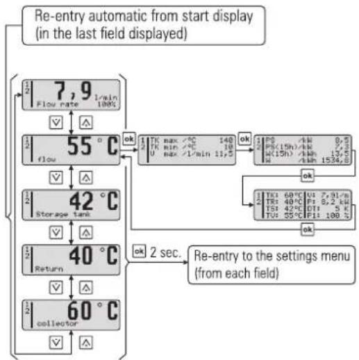
- Pushing the arrow keys allows you to navigate between the 4 temperature measured values and the flow rate measured value (see Tab. 5-2 and Tab. 5-6) (without FlowSensor only between 3 temperature measured values).
- Press the Info button to show the maximum and calculated values (see Tab. 5-3).
The left column of the display is the status display. This means:
- "1" in first row, solar circuit pump P _S is active.
- "2" in the second row, BSK contact for solar priority active (see Section 5.4).
- "K" in the 3rd row, solar panel sensor defective, or a different error status (see Chapter 6.2).
- "H" in the fourth line, manual mode active.
i
So long as no manual adjustments are made or an event corresponding to Tab. 6-2 produces a different display, the actuated measured value or information display remains active. It is also reactivated after parameter changes or switching off and on. If information values are displayed, no measuring point indicator light is activated.
flowchart
graph TD
    A["Switch on main switch, all lights on (apart from pump pilot lights)"] --> B["EKSR3Pa U.3.8 20<br>Rup 10 2009 11:30:43<br>DalKIN<br>Ser.-N=1000001066652"]
    B --> C["3 sec., then lights off."]
    C --> D["only during first commissioning"]
    D --> E["--Sprache andern---aktuell deutsch"]
    E --> F["ok"]
    F --> G["--Sprache andern---aktuell English"]
    G --> H["ok"]
    H --> I["Language setting"]
    I --> J["saved"]
    J --> K["for operational display"]
    D --> L["2 sec. Delta T on /K"]
    L --> M["2"]
    M --> N["Delta T off /K"]
    N --> O["2 sec. Delta T off /K"]
    O --> P["2 sec. 35 ZPsE /="]
    P --> Q["2 sec. 80 TS max /=C"]
flowchart
graph TD
    A["Re-entry automatic from start display (in the last field displayed)"] --> B{Flow rate 7.9 min 100%}
    B --> C["Flow 55°C"]
    C --> D{OK}
    D --> E["TK max /°C 140<br>TK min /°C 10<br>U max /L/min 11.5"]
    E --> F["OK"]
    F --> G["P0 60°C U1 7.31/s<br>P0 40°C P2 8.2 kW<br>T0 42°C DT1 5 K<br>T0 35°C P11 100%"]
    G --> H["OK"]
    H --> I["Tk 60°C U1 7.31/s<br>T0 40°C P2 8.2 kW<br>T0 42°C DT1 5 K<br>T0 35°C P11 100%"]
    I --> J["OK"]
    J --> K["Return"]
    K --> L{OK 2 sec.}
    L --> M["60°C collector"]
    M --> N["Return"]
Fig. 5-7 Start display Fig. 5-8 Operating display with connected FlowSensor EKSFLP12A
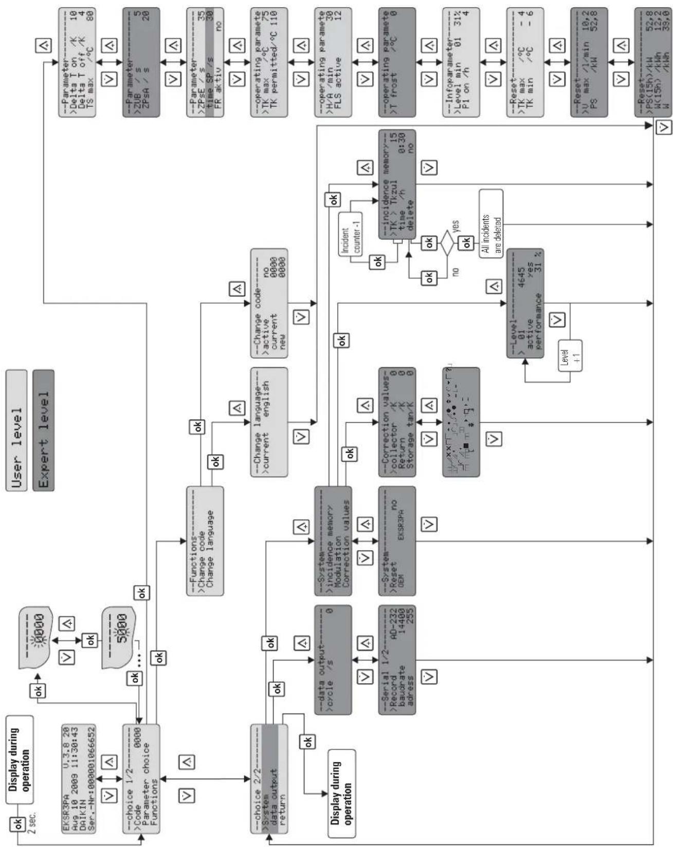
5.3.3 Settings menu
The solar control system parameters are displayed and changed in the menu.
- Press once (>2 s) on the OK pushbutton to open the menu or to return to the operating display. Press briefly to confirm a selection, open the next menu display or "Saved" is shown for approx. 1 s if a value is changed.
- In the required parameter display press OK to open parameter change mode.
In the menu (Fig 5-9) the active menu path is displayed in the first line, a cursor (" > ") in the left column indicates the next lower menu path or a parameter. Then use the arrow keys to scroll up (+ pushbutton) or down (- pushbutton) in the menu tree. The set value can be modified with the arrow keys.
A short press on the arrow key changes the value one step, press and hold to make larger changes.
If the desired parameter has been changed and the complete parameter list scrolled through to the bottom, the user is returned to the selection menu "Selection 2/2" and then to the operating display (see Fig 5-9). The control system now operates immediately with the modified parameter values. The control system always jumps back to the operating mode if no button is pressed for about 10 minutes.
flowchart
graph TD
    A["User level"] --> B["Expert level"]
    B --> C["Display during operation"]
    C --> D["OK"]
    D --> E["OK"]
    E --> F["5000"]
    F --> G["---choice 1/2----Code 0000 Parameter choice Functions"]
    G --> H["OK"]
    H --> I["---Functions----Change code Change language"]
    I --> J["OK"]
    J --> K["---Change language----current english"]
    J --> L["---Change code----active no current new 0000"]
    K --> M["---data output----cycle /s 0"]
    L --> N["---Incidence memory Modulation Correction values"]
    M --> O["---Serial 1/2----Record 14400 address AD-232 255"]
    N --> P["---System----Reset no OEM EKSR3PA"]
    O --> Q["---Correction values----collector /K 0 Return /K 0 Storage tan/K 0"]
    P --> R["---Level---->01 4645 active yes performance 31% Level +1"]
    Q --> S["---Incidence memory----TK > Tkzul 15 time /h delete no Incident counter -1"]
    S --> T["---Incident counter -1"]
    T --> U["---Incident values----no yes all incidents are deleted"]
    U --> V["---Reset---->U max /l/min 10,2 PS /kW 52,8 Reset---->PS(15h)/kW 52,8 W(15h) /kWh 12,2 W /kWh 39,8"]
    V --> W["---Parameter---->Delta T on /K 10 Delta T off /K 4 TS max /°C 80"]
    W --> X["---Parameter---->ZUB /s 5 ZPsA /s 20"]
    X --> Y["---Parameter---->ZPsE /s 35 time SP /s 30 FR aktiv no"]
    Y --> Z["---operating paramete >TK max /°C 75 TK permitted/°C 110"]
    Z --> AA["---operating paramete >H/A min 30 FLS active 12"]
    AA --> AB["---operating paramete >T frost /°C 0"]
    AB --> AC["---Infoparameter---->Level min 01 31% PI on /h"]
    AC --> AD["---Reset---->TK max /°C -4 TK min /°C -6"]
    AD --> AE["---Reset---->U max /l/min 10,2 PS /kW 52,8 Reset---->PS(15h)/kW 52,8 W(15h) /kWh 12,2 W /kWh 39,8"]
Fig. 5-9 Settings menu
5.3.4 Password input
The technician area of the settings menu is protected by a password, which is entered when opening the settings menu. The user level can also be password-protected. The user level and the technician level are shown in different colours in the settings menu. In addition to the path described in Fig 5-9 the user can press and hold the up arrow key (+) to open the settings menu during the control systems start display.
Password input is not required while the unit is under manual operation. A password remains valid for approx. 10 min after the last pushbutton press. After entering the password, the desired level is available for 2 s:
- "User OK",
- "Technician OK" or
- "Password incorrect".
User password
This password is not activated in the factory setting of the solar control system. A 4-digit numerical code can be entered to protect all adjustable parameters in the user level from unauthorised access (child protection or concierge function). The parameters of the user level can only be modified with a deactivated user password or with a valid user password.
A user password can be activated and changed or reassigned in the following menu path: "Selection 1/2" -> "Functions" -> "Change passw." (see Fig 5-9):
- Enter old password into "current 0000" and new into "new 0000". Confirm every digit of the password with OK.
- For a new password, enter the new password in "current 0000" and also in "new 0000".
If the user password is activated, the menu path "Selection 1/2" only shows "Password 0000". The user password only becomes active after 10 min or after the solar control system is restarted.
Technician password
The password is entered in the menu path: "Selection 1/2" at "Password 0000". It activates all important systems parameters in the settings menu for technicians (see Fig 5-9).
5.3.5 Language selection
At initial start-up or after a global reset the display (Fig 5-7) stops during start-up and the user is prompted to select the language. - Select a language with arrow keys and confirm with OK.
Open the settings menu in the menu path: "Selection 1/2" -> "Functions" -> "Change language" to select a different language (see Fig 5-9):
5.3.6 Setting and resetting parameters
Setting the parameters is in accordance with Fig 5-9. All adjustable parameters are shown with access level, adjustment range and factory setting in the Tab. 5-5. In the menu path: "Selection 1/2" -> "Parameter selection" -> "Reset" the maximum values and calculated values (see Tab. 5-5) can be reset. The selected maximum value is immediately set to "0" using the OK button.0 Cancel the action with the down arrow key and the cursor returns to the left. Press OK to confirm the selection. Press the down arrow key repeatedly to open "Selection 2/2". Confirm "back" to return to the operating display. In the menu path:
"Selection 2/2" -> "System" -> "Reset" all system parameters can be reset to the factory settings. The system is then restarted (see also section 5.2.8).
5.3.7 Manual setting of the pump speed regulation (only with connected FlowSensor EKSFLP12A)
At some output stages of the speed-controlled pump P_S noise problems may be encountered occasionally. The actual output of the selected stage is displayed as a percentage in the bottom line "Flow" in the operating display (see Fig 5-8).
- Note the output of the problematic stage.
- In the menu path: "Selection 2/2" -> "System" -> "Modulation" go to "Stage" (see Fig 5-9).
Up to 10 speed stages can be disabled here. The percentage output for the various stages is displayed under "Output" as well as the allocation number of the output stage (starting with 01 for the lowest output) and the activity status.
- Set the noise-intensive stage to "no" under the parameter "active".
→ The stage will be skipped during actuation of pump .
5.3.8 Correction values for measuring points
If the measured value of a sensor deviates from the actual value, it can be compensated with a correction value.
- In the menu path: "Selection 2/2" -> "System" -> "Correction values" select the correction parameter (see Fig 5-9) and modify values Tab. 5-4 accordingly.
| Designation Access level | Measurement/set-ting/value range | Factory value Increment | |
| Solar panel temperature correction | 90 K 1 Kto +DehKičian0 K 1 K | -9 to +90 K 1 K | |
| Return temperature correction -9 to + | |||
| Storage tank temperature correction -9 to + | |||
| Feed temperature correction -9 to +9 | |||
| Flow correction | -2 to +2 | 0 l/min | |
Tab. 5-4 Correction values
5.4 Recommended settings
5.4.1 Standard parameter settings, recommended setting ranges
The following table summarises the factory settings and the possible and recommended setting ranges of the solar system parameters.
| Parameter | Designation | Access level | Setting range | Recommended setting range | Factory setting | Increment | |
| BE | FA | ||||||
| Delta T on | Cut-in temperature difference | x | x | 1...80 (> "Delta T off") | 10 to 15 K | 15 K | 1 K |
| Delta T off | Cut-out temperature difference | x | x | 1...20 (< "Delta T on") | 2 to 5 K | 4 K | 1 K |
| T_S max | Maximum storage tank temperature | x | x | 20 to 85°C | 75 to 85°C | 80 °C | 1 K |
| Time PsE | Switch-on delay BSK | x | x | 0 to 600 s | 20 to 40 s | 35 s | 1 s |
| Time PsA | Switch-off delay BSK | - | x | 0 to 600 s | 15 to 30 s | 20 s | 1 s |
| Time UB | Reverse condition delay time | - | x | 0 to 600 s | 5 to 20 s | 5 s | 1 s |
| Time Sp | Pump blocking time | - | x | 0 to 600 s | - | 30 s | 10 s |
| T_K max | Booster temperature (maximum solar panel temperature) | i | x | 20 to 110°C | - | 75 °C | 1 K |
| T_K zul | Cut-in protection temp. (max. approved operating solar panel temp.) | i | x | 90 to 130°C | - | 110 °C | 1 K |
| T_R min | Minimum temperature storage tank | - | x | 0 to 10°C | - | 0 °C | 1 K |
| H/A | Automatic reset from manual to automatic mode | i | x | 1 to 900 min | - | 30 min | 1 min |
| FLS active | Activation FlowSensor | i | x | no / 12 | 12 | without FLS: no with FLS: 12 | no / 12 |
| Cycle | Cycle of data output (serial interface RS 232) | - | x | 0 to 300 s | - | 0 | 5 s |
| Baud rate | Step speed of data output | - | x | 2400, 4800, 9600, 19200 | - | 19200 | - |
Tab. 5-5 Parameter overview
| BE | User | x | adjustable |
| FA | Technician | i | informative |
| - | not available |
i
The system parameters at start-up must be set individually to the installed system situation and if necessary optimised during operation. In general, the system operates with the factory settings.
The following information will assist with calculating the settings and will guarantee optimum heat yield with low power consumption:
- Set the cut-in temperature difference "Delta T on" so the system remains operating after start-up under steady solar radiation conditions and does not shut down immediately the solar panels cool down after removing heat. The lower the selected value can be the longer operation times and therefore the greater the achievable heat yields. If the cut-in temperature difference is set too low the solar panels will cool down as soon as the pumps are started enough to fall below the cut-out temperature difference.
→ The pumps will shut down immediately and less heat will be obtained at high power consumption. - Set the cut-out temperature difference "Delta T off" so the available heat output at the cut-out point is higher than the electrical power required to operate the pumps.
→ Because the power consumption of the pumps is virtually independent of the area of the solar panels but the available heat output depends directly on the number of solar panels, the parameter value is set higher with fewer solar panels and lower with more solar panels. - Set the cut-in delay for the tank circulation pump "Time PsE" so hot water is at the plate heat exchanger of the solar connection kit EKSOLHWAV1 until the tank circulation pump starts.
- The maximum storage tank temperature "T _S max" is set appropriately for the individual requirements. The higher the parameter value the higher the available heat storage capacity and therefore the potential output of the solar system.

CAUTION!
If storage tank temperatures are over 60 °C a thermal mixing valve must always be installed at the hot water connection of the storage tank for scalding protection.
The cut-in protection temperature " T_K zul" is preset at the factory to prevent noise and steam formation. The solar control system only switches on the pumps if the solar panel temperature has exceeded the defined parameter value once by 2 K. The system operates without forming steam in the solar panels. However, on a cloudless day this may cause the system to switch on again only in the late afternoon, although the storage tank temperature allows additional heating.
- To maximise the energy input set the "cut-in protection temperature parameter" to a value greater than 110 °C and therefore deactivate the cut-in temperature protection function. The owner of the system must be informed of possible audible bubbling noises and vapour pressure pulses during start-up in this case.
5.4.2 Additional settings for your solar system

During operation of the solar system with FlowSensor the flow in the solar system is continuously adjusted for the requirements with the differential temperature-dependent control system of pump P_S .
The following information on adjustments is applicable for operation without FlowSensor only:
Set the water flow in the solar panel circuits so the flow through every solar panel is 90 to 120 l/h. Either match the flow rate by setting the speed stage on the solar circuit pump and by throttling on the isolation in the flow meter of the pump unit EKSRDS1A (Chapter 3 "Montage", Fig 3-4, Item 10). Reference values for correct valve and pump stage settings are listed in Tab. 5-6.
Always observe the system temperatures during normal system operation as indirect control of the flow volume. Under optimum solar radiation (clear sky, clear air, sun vertical to solar panels) the temperature increase in the solar panels should be about 10 to 15 K. During operation with pump P_S for example at a return temperature of 50 °C, set the solar panel temperature at 60 to 65 °C. If a heat meter is installed in the building, the flow volume can be set by direct measurement during operation of the pump.
| Number of solar panels | Set flow rate in l/min on solar panel circuit | Set flow rate in l/h on solar panel circuit |
| 2 3.6 to 4 | 8 220 to 290 | |
| 3 5.4 to 7 | 2 330 to 435 | |
| 4 7.2 to 9 | 6 435 to 580 | |
| 5 9 to 12 | 540 to 720 |
Tab. 5-6 Setting the flowrate on the flow meter

Even if the flow volume is set correctly, the cut-in temperature difference "Delta T on" and good weather conditions will occasionally shut down the solar system. With the sun rising or setting and an increasing storage tank temperature the solar panel temperature will fall slowly after starting the pumps, the cut-out condition will be reached. The continuing solar radiation will increase the temperature of the solar panels, the pumps will operate and the system will cycle because the solar radiation is no longer sufficient for continuous operation. The FlowSensor reduces this effect by controlling the pump speed.
Follow the setting instructions in the installation and operating instructions of the connection kit EKSOLHWAV1.
5.4.3 Domestic water hygiene
If no hot water is drawn off for several days and if the storage tank temperature does not reach at least 60 °C as a result of the solar system, one-off heating to over 60 °C or draining of the stored hot water is recommended for hygienic reasons (Legionella protection).
6.1 Event display
Using the menu path: "Selection 2/2" -> "System" -> "Event memory" and after input of the technician password (see chapter 5.3.4 and figure 5-9) the events occurring during operation can be displayed. For this purpose, the solar control system has a simple remote fault diagnosis system. The type and time of the event are stored on the event storage. The event is displayed in plain text and in code, the time of the start of the event is displayed in hours. The individual events can be scrolled through with the Info button starting from the most recent. If the parameter "Delete" is in the menu path: "Selection 2/2" -> "System" -> "Event memory" is set to "yes", all events are deleted. Deleting an individual event is not possible. An overview of the event storage is given in Tab. 6-1.
| Event code | Plain text display | Description Status | display (flashing) | Lamp (flashing) | Consequence |
| 0 Solar panel Solar | panel sensor: short-circuit or interruption K TK | Long-term switch off of P_S and BSK=0 | |||
| 1 | Return flow | Return flow sensor: short-circuit or interruption | R | TR | |
| 2 | Storage tank | Storage tank sensor short-circuit or interruption | S | TS | |
| 3 | Flow rate | FlowSensor: Short circuit or interruption | D | Operation without FlowSensor | |
| 4 | Flow | FlowSensor: Short circuit or interruption | V | ||
| 5 | A/D | Internal A/D converter fault | G | Long-term switch off of P_S and BSK=0 | |
| 6 | Supply | Internal equipment fault of the supply voltage | G | ||
| 7 | Reference | Internal equipment fault of the reference voltage | G | ||
| 8 | reset | General reset has been carried out | G | Parameters to factory settings, restart the equipment | |
| 12 | Start flow | Minimum flow rate V1 (Page 25, Fig 5-4) was not reached in the start phase after expiry of "Time PsE" - see Chapter 5.2.9 | W | TV | Temporary switch off of P_S and BSK=0 (2 h / 3 start attempts) |
| F | Long-term switch off of P_S and BSK=0 | ||||
| 13 | T_S>T_max | Maximum storage tank temperature (" T_S max") exceeded (see Chapter 5.2.1 and Chapter 6.2 | TS | Temporary switch off of P_S and BSK=0 | |
| 14 | T_R>T_S | T_R-T_S>10K and T_R>40°C -see Chapter 6.2 | TR | ||
| 15 | T_K>T_Kzul | Maximum permissible solar panel temperature (" T_Kzul ") exceeded - see Chapter 5.2.1 and Chapter 6.2 | TK | ||
| 16 Collapse Flow breakdown during operating phase detected (V < "S-Flow") - see Page 25, Fig 5-4 and Chapter 5.2.9 | Temporary switch-off of P_S blockage of the current and lower pump modulation stage. | ||||
Tab. 6-1 Event storage
Sensor-specific fault signals
The solar control system reacts as follows when the cable is broken or in the event of a short circuit in the sensors or sensor cables (see Tab. 6-2):
- The display shows a flashing letter in the status line to indicate the fault and a message is shown.
– The lamp associated with the sensor flashes. - In addition, the solar control system automatically intervenes in the operation of the system.
All other sensor values can still be reached using the arrow keys.
| Sensor Cause of the fault | Status (flashes) | Display Lamp (flashing) | Consequence | ||
| Solar panel temperature | Interruption K uuuu TK | Long-term switch off of PS and BSK=0 | |||
| Short circuit ---- TK | |||||
| Return flow temperature | Interruption R uuuu TR | ||||
| Short circuit ---- TR | |||||
| Storage tank temperature | Interruption S uuuu TS | ||||
| Short circuit ---- TS | |||||
| Feed temperature V | Voltage drop V | ---- | without lamp | Operation without FlowSensor | |
| Flow sensor | Voltage drop | D | ---- | without lamp | |
Tab. 6-2 Sensor fault table
6.2 Troubleshooting
Fault-type operational events:
Storage tank temperature "T S " in the hot water storage tank reaches the value set in parameter "T S max":
- Solar circuit pump P_S is switched off and BSK contact for solar priority open. In the solar control system the T_S lamp flashes, the display shows the measured storage tank temperature. If the storage tank temperature falls by more than 2 K, normal system operation is released again automatically.
Temperature in the solar panels is higher than the cut-in protection temperature "T _K zul":
- Solar circuit pump P_S is switched off and BSK contact for solar priority open. The T_K lamp flashes in the solar control system. If the set cut-in protection temperature falls by more than 2 K, normal system operation is automatically enabled.
Malfunctions:

WARNING!
Live parts can cause an electric shock on contact and cause life-threatening burns and injuries.
- Electrical installations must always be carried out by qualified electrical technicians in conformity with the relevant electrical guidelines and the regulations of the electric utilities company to prevent hazards from damaged electric wiring.
- Rectification of damage to live components of the EKSR3PA + EKSRDS1A must only be carried out by heating engineers authorised and recognised by the energy supply company.
- Before starting any maintenance work on the central unit disconnect the EKSR3PA + EKSRDS1A from the power supply (switch off fuse, main switch) and secure it against unintentional restart.
-
Comply with the relevant safety at work regulations.
-
The T_K lamp flashes in the solar control system. Return flow temperature " T_R " is greater than 40 °C and is 10 K over the storage tank temperature " T_S ". The pumps are switched off. The cause can be a defective or a wrongly connected sensor. Also unsuitable or deliberate control settings made at the air-water heat pump can lead to this operation condition.
-
Fit the sensor correctly or replace it, the normal system operation is automatically released again.
-
Check controller settings on the air-water heat pump and adapt to suit (observe Installation and Operating Instructions of the solar connection kit EKSOLHWAV1).
-
The fault signal "W" is shown in the left column of the solar control system display.
During the start procedure after expiry of time PsE and time UB the minimum flow corresponding to start phase "V1" Tab. 5-1 was not reached at the FlowSensor. The cause can be vapour production when starting the pump from the stagnation phase, in which the solar panels can get very hot and the solar fluid has vaporised in the solar panel. The system is temporarily blocked for 2 h and then automatically attempts to start.
The causes may include:
- a fault in the FlowSensors or
- vapour formation in the solar circuit or
- a leak in the solar panel circuit.
-
If a leak is suspected, inspect the solar system, repair damage and then disable the block by switching the control system off and on.
-
The fault signal "F" is shown in the left column of the solar control system display. It follows three "W" fault signals with 2 h block time each. The system is now completely blocked and can only be restarted by user intervention. The causes may include:
-
a fault in the FlowSensors or
- vapour formation in the solar circuit or
- a leak in the solar panel circuit.
-
If a leak is suspected, inspect the solar system, repair damage and then disable the block by switching the control system off and on.
-
If circulation cannot be generation in the tank or solar panel circuit, it may be caused by the following faults:
a) Air in the pump of the affected circuit.
- Check the pump for air.
- Check system pressure and, if necessary, top up heating water or solar fluid.
b) Check system for tightness
- Check system for tightness and seal if necessary. In doing so, observe the instructions in Chapter 4 "Inbetriebnahme und Außerbetriebnahme".
-
Check the safety valve of the affected circuit for leaks.
c) Increase the capacity of the pumps at the selector switch (1, 2, 3) for the individual pump. -
If the display is without display and the main switch is in the illuminated "ON position":
-
Replace the solar control system (electronic fault).
- If the main switch is not lit up in the "ON position" there is no power supply to the unit.
- Check the plug connection of the mains plug and the domestic power supply (fuse, switch).
Special instructions for electrical sensors

Use only original DAIKIN spare parts.
- Evaluate the display of the solar control system EKSR3PA.
- Remove casing of control unit and remove and disconnect the relevant sensors.
- Check the contact points of the sensor in question, if necessary measure the resistance (or the DC voltage for feed temperature and flow rate sensors) on the sensor side.
If the fault has been rectified the system automatically switches to normal operation and will be in the operating mode.
The resistance or DC voltage measurements of the sensors are listed in Fig 7-2. Diagnosable internal faults of the control electronics are shown in the display according to Tab. 6-1 (status G). They also effect a safety switch-off of the pumps.
Switching off and on again after waiting for 2 min will either correct the fault or the solar control system must be replaced.
7.1 Basic data
| Controller EKSR3PA | |
| Dimensions W x T x H 230 x 815 x 142 cm | |
| Operating voltage 230 V / 50 Hz | |
| Control Digital differential temperature regulator with plain text display | |
| Max. electrical power consumption of the control system | 2 W |
| solar panel temperature sensor Pt 1000 | |
| Storage tank and return flow temperature sensor PTC | |
| Feed temperature and flow sensor (optional) EKSFLP12A | |
Tab. 7-1 Technical data control unit
| Pump unit EKSRDS1A | |
| Dimensions W x T x H 240 x 410 x 130 cm | |
| Operating voltage 230 V / 50 Hz | |
| Solar panel circulation pump Grundfos Solar 25-65 130 | |
| Max. electrical power consumption of the pump 52 W | |
| Max. operating pressure 6 bar | |
| Max. pump capacity 2 m3/h | |
| Pressure gauge 0 - 10 bar | |
| Temperature range | 0 - 120 °C (short-term 160 °C) |
| Connections | 4x 1 1⁄4" female for ∅ 22 clamping ring bolt |
Tab. 7-2 Technical data pump unit
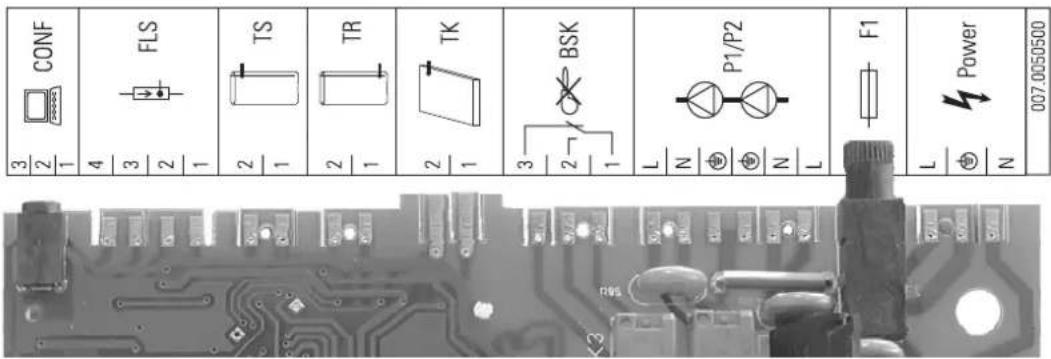
Fig. 7-1 Connection assignment
| CONF | Programming socket for software updatesTR | |
| FLS | FlowSensor EKSFLP12A (accessory) | TK |
| TS | Storage temperature sensor t_S2 | BSK |
| Return flow temperature sensorP1/P2 | Solar panel circulation | |
| Solar panel temperature sensor | pump P_S | |
| Connection cable for solar priority | F1 | Fuse |
| Power | Power supply | |
7 Technical data
| Temperature sensor | |||||||||||||||||||
| Solar sensor Sensor type Measured temperature in °C | |||||||||||||||||||
| - 2 | 0 | - | 1 | 0 | 0 | 1 | 0 | 2 | 0 | 3 | 0 | 4 | 0 | 5 | 0 | 6 | |||
| Sensor resistance in Ohm according to standard or manufacturer's data | |||||||||||||||||||
| TR, TS PTC 1386 | 1495 1630 1 | 772 19 | 22 2080 | 2245 | 2418 | 25 | 98 2786 | 2982 | 3185 | 3396 | |||||||||
| TK PT-1000 922 | 961 1000 103 | 39 1077 | 1116 1 | 155 11 | 94 1232 | 1270 | 1308 13 | 47 1385 | 1423 | 1461 | |||||||||
| FlowSensor | Sensor voltage in V according to manufacturer data | ||||||||||||||||||
| TV | (0.50 - 3.50 V) | 0.50 | 0.80 | 1.10 | 1.40 | 1.70 | 2.00 | 2.30 | 2.60 | 2.90 | 3.20 | 3.50 | |||||||
| Flow rate | |||||||||||||||||||
| Solar sensor Sensor type Measured flow rate in l/min | |||||||||||||||||||
| FlowSensor | 0.0 | 2.0 | 4.0 | 6.0 | 8.0 | 10.0 | 12.0 | 14.0 | 16.0 | 18.0 | 20.0 | ||||||||
| Sensor voltage in V according to manufacturer data | |||||||||||||||||||
| V | (0.36 - 3.50 V) | 0.36 | 0.67 | 0.99 | 1.30 | 1.62 | 1.93 | 2.24 | 2.56 | 2.87 | 3.19 | 3.50 | |||||||
Tab. 7-3 Sensor table of the solar sensors
0 7
7.2 Diagrams
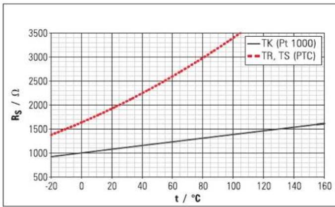
line
| t / °C | TK (Pt 1000) | TR, TS (PTC) | | ------ | ------------ | ------------ | | -20 | 950 | 1400 | | 0 | 1050 | 1600 | | 20 | 1150 | 1850 | | 40 | 1250 | 2150 | | 60 | 1350 | 2500 | | 80 | 1450 | 2850 | | 100 | 1550 | 3250 | | 120 | 1650 | 3550 | | 140 | 1750 | 3750 | | 160 | 1850 | 3750 |Fig. 7-2 Resistance characteristics of the solar sensors
R_S Sensor resistance (PTC, Pt 1000) t Temperature
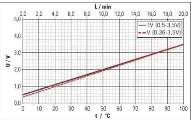
line
| t / °C | TV (0.5-3.5V) | V (0.36-3.5V) | | ------ | ------------- | ------------- | | 0 | 0.5 | 0.4 | | 10 | 1.0 | 0.8 | | 20 | 1.5 | 1.3 | | 30 | 2.0 | 1.8 | | 40 | 2.5 | 2.3 | | 50 | 3.0 | 2.8 | | 60 | 3.5 | 3.3 | | 70 | 4.0 | 3.8 | | 80 | 4.5 | 4.3 | | 90 | 5.0 | 4.8 | | 100 | 5.5 | 5.3 |Fig. 7-3 Characteristics of the FlowSensor
L Flow rate t Temperature
B
Brief description 8
BSK - solar priority .....14, 21, 22, 23, 26, 28, 31, 34, 35, 37
C
Control
Brief description 8
Language selection 30
Manual operation 23
Operation 21
Password input 30
Control and pump unit
Manual speed control 30
Technical data 37
Control unit 8
D
Danger of frost 20
E
Explanation of symbols 5
F
Filling the system 17, 18, 19, 23, 27
Flow
Control system display 28
Correction values 31
Display flow meter 21
Flow meter measuring section 27
Flowmeter solar panel circuit 23
Minimum flow rate 24, 25, 26, 33
Set values 33
Flow rate
Filling position of flow meter 17
Flowmeter solar panel circuit 11, 13
Malfunction 34, 35
Set values ...... 19, 38
Setting solar panel circuit 19
FlowSensor 9, 16, 19, 23, 27, 31, 34, 37, 38
Frost protection function 26
|
Installation
Connection pipes 11
Control unit 12
FlowSensor 16
Preparatory activities 10
Pump unit 11
Storage temperature sensor 12
L
Language selection 30
M
Malfunctions
Event display 34
Rectification 35
N
Noise problems 30
0
Operating safety 6
P
Parameter 31
Flow at FlowGuard 19
Flow rate on the flow rate regulator 33
Recommended setting ranges 31
Proper use 6
Pump unit 9
s
Shutdown 20
Final 20
Temporary 20
Solar connection kit 9
Solar module 9
Solar system
Design 7
Operating mode 8
Speed control automatic 24
Manual setting pump speed 30
Start-up 17,23
Storage tank 8
Switch-off delay BSK 22, 26, 31
Switch-on delay BSK 22, 26, 31, 32
System concepts .... 10
T
Taking out of service 17
Technical data 37
Thermal transfer medium 8,17
V
Vent system 18, 19
- Control and pump unit for solar systems
- Safety 5
- Product description....7
- Installation 10
- Start-up and taking out of service.... 17
- Operation.... 21
- Faults and malfunctions.... 34
- Technical data.... 37
- List of keywords.... 39
- Observing Instructions
- Relevant documents
- Warning signs and explanation of symbols
- Meaning of the warnings
- DANGER!
- WARNING!
- CAUTION!
- Special warning symbols
- Handling instructions
- Avoid danger
- Proper use
- Instructions for operating safety
- Working on the roof
- Before working on the heating system
- Electrical installation
- Instructing the user/owner
- Design and components of the solar system
- Brief description
- Operating mode
- Modular design
- Storage tank
- Electronic control
- System components
- Controller EKSR3PA
- Consists of:
- Pump unit EKSRDS1A
- Solar connection kit EKSOLHWAV1
- Solar module EKRP1HBAA
- Accessories
- FlowSensor EKSFLP12A
- System concepts
- Serial connection
- Preparatory installation work
- i
- General installation instructions
- Installing the clamping ring bolt:
- Controller EKSR3PA
- Wall mounting
- Electrical connections
- Pump unit EKSRDS1A - electrical connection
- Storage temperature sensor
- FlowSensor (optional)
- Initial start-up
- Filling solar panel circuit
- Regulate the flow rate on the solar panel circuit
- Filling the storage tank and heating circuit
- Taking out of service
- Temporary shutdown
- Final shutdown
- Recommendations for disposal
- Operating and display components
- Operation of control systems
- Pump operation
- Criteria for switching off:
- Contact for Solar Priority (BSK)
- Switch-on lock-out function
- Manual operation
- Solar FlowSensor EKSFLP12A
- Output calculation, maximum values and yield count
- Speed regulation of the solar circuit pump P s
- Global reset function
- Frost protection function
- Leak protection function
- Setting and menu operation
- Start display
- Operating display
- Settings menu
- Password input
- User password
- Technician password
- Language selection
- Setting and resetting parameters
- Manual setting of the pump speed regulation (only with connected FlowSensor EKSFLP12A)
- Correction values for measuring points
- Recommended settings
- Standard parameter settings, recommended setting ranges
- Additional settings for your solar system
- Domestic water hygiene
- Event display
- Sensor-specific fault signals
- Troubleshooting
- Fault-type operational events:
- Malfunctions:
- Special instructions for electrical sensors
- Basic data
- Technical data
- Diagrams
- B
- C
- D
- E
- F
- |
- L
- M
- N
- 0
- P
- s
- T
- V
Brand : DAIKIN
Model : EKSRDS1A
Category : Chauffe-eau instantané et ballon d'eau chaude