
9401A - Uncategorized GENELEC - Free user manual and instructions
Find the device manual for free 9401A GENELEC in PDF.


| Product Type | Multichannel Audio-over-IP Interface |
| Brand | Genelec |
| Model | 9401A |
| Dimensions (H x W x D) | 43 x 483 x 105 mm (1 11/16 x 19 x 4 1/8 in) |
| Weight | 2 kg (4.4 lbs) |
| Mains Input Voltage | 100-240 VAC, 50-60 Hz |
| Operating Power Consumption | 12 W |
| Idle Power Consumption | 9 W |
| ISS State Power Consumption | 4.5 W |
| Digital Audio Input Formats | ST2110-30, AES67, Ravenna |
| Digital Audio Output Format | AES/EBU (AES3-2003) |
| Sample Rate Range | 44.1 kHz to 192 kHz |
| Word Length | 16 to 32 bits (AES/EBU outputs max 24 bits) |
| Audio Output Channels | 16 channels via DB25, plus subwoofer link (AES/EBU XLR) and aux stereo (AES/EBU XLR) |
| Network Interface | 2 x RJ-45 for 1000BASE-T (Cat 5e or better) |
| Redundant IP Input | ST2022-7 compliant with seamless handover |
| Clock Synchronization | IEEE1588-2008 PTPv2 |
| Operating Temperature | 15-35 °C (59-95 °F) |
| Operating Humidity | 20% to 80% non-condensing |
| EMC Compliance | FCC Part 15 Class B, CE |
| Included Accessories | Mains cable, 5 m GLM network cable, Quick Setup Guide |
| Configuration | Genelec Loudspeaker Manager (GLM) software and HTTP web interface |
| Power Saving | Intelligent Signal Sensing (ISS) with configurable timeout |
| User Serviceable Parts | None; maintenance by certified personnel only |
Frequently Asked Questions - 9401A GENELEC
User questions about 9401A GENELEC
0 question about this device. Answer the ones you know or ask your own.
Ask a new question about this device
Download the instructions for your Uncategorized in PDF format for free! Find your manual 9401A - GENELEC and take your electronic device back in hand. On this page are published all the documents necessary for the use of your device. 9401A by GENELEC.
USER MANUAL 9401A GENELEC
natural_image
Front view of a black GENELEC rack with indicator lights and wiring diagram (no readable text or symbols beyond branding)Genelec 9401A Multichannel Audio-Over-IP Interface


Introduction
Congratulations and thank you for purchasing the Genelec 9401A multichannel audio-over-IP (AoIP) interface. This manual addresses the setting up and use of the Genelec 9401A intended for use with 7300 Series subwoofers.
The Genelec 9401A enables Smart Active Monitoring (SAM) monitors and subwoofers to receive multichannel audio presentations using standard AoIP networks. The 9401A offers 16 channels of AES-EBU digital audio feeds for SAM monitors and a dedicated AES/EBU interface for 7300 series Smart Active Monitoring (SAM) subwoofers, as well as an auxiliary AES/EBU output for supporting monitoring systems, such as headphones.
The 9401A enables the monitoring of immersive digital audio, supporting monitoring layouts up to 9.1.6 configuration when the low frequency effects (LFE) channel is also used.
The auxiliary AES/EBU output can be used to connect, for example, an additional stereo monitor system or headphones when a digital-to-analog interface device and a headphone amplifier is used.
Genelec's energy-saving Intelligent Signal Sensing (ISS) function automatically puts the 9401A into a power-save state when no AoIP stream is present. The waiting time before activation can be configured using Genelec Loudspeaker Manager (GLM) software. When ISS is on your monitoring system will remain ready for action and the 9401A will consume less than 4.5 watts of power. The interface will wake up and switch to normal operating mode when it senses an AoIP stream.
This 9401A is supplied with:
- Mains cable
- 5 m GLM network cable
- Quick Setup Guide
- Operating manual via QR code
The 9401A uses in addition a standard CAT cable for the IP network connection.
Installation
We strongly recommend switching off/disconnecting mains power from all system devices before connecting signal cables.
Connections
Pay attention to the GLM network and Ethernet connectors. The GLM network uses the 8P8C (RJ45) connector but is not compatible with Ethernet or Power over Ethernet (PoE).
The mains input supports a wide voltage range (100-240 VAC, 50-60 Hz). If the mains power is provided by a generator, inverter or a low-quality UPS device, we recommend using a harmonic filter to reduce the unwanted harmonic distortion.
The two digital audio stream inputs for ST2110, AES67 or Ravenna digital audio stream uses a standard 1000BASE-T compatible network interface with an RJ45 connector. The two inputs offer redundancy and can be configured for fast and seamless hand-over in case of the failure in the primary stream input.
When the audio content in the stream carries a low frequency effects (LFE) channel, the 9410A is configured to extract the correct channel as the LFE content and assign the LFE content to the AES/EBU output and subframe by using the GLM software.
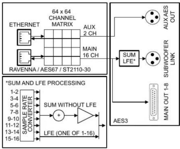
The multichannel audio output for the monitors uses one DB25 connector to deliver 8 AES/EBU audio signals, carrying 16 channels of audio. The output is a bit-to-bit copy of the stream content audio signals, so the outputs retain the original signal quality without modification. When used, the LFE signal is output using the subwoofer interface and is also available through the DB25 connector, meaning that the LFE content is available for any device connected to this output. The content of the multichannel audio output is configured using the HTTP web interface.
The digital audio output for the subwoofer is a single male XLR connector, which uses an AES/EBU cable to carry the sum of all the main channel inputs over one AES/EBU subframe and the LFE channel, if used, over the other AES/EBU subframe. A GLM Kit or SAM Reference Controller (RC) and Genelec
flowchart
graph TD
    A["ETHERNET"] --> B["64 x 64 CHANNEL MATRIX"]
    C["RAVENNA / AES67 / ST2110-30"] --> B
    B --> D["AUX 2 CH"]
    B --> E["MAIN 16 CH"]
    F["AUX AES OUT"] --> G["SUM LFE*"]
    H["SUBWOOFER LINK"] --> I["SUBWOUFER"]
    J["AES3"] --> K["MAIN OUT 1-8"]
    L["*SUM AND LFE PROCESSING"] --> M["SAMPLE RATE CONVERTER"]
    M --> N["SUM WITHOUT LFE"]
    N --> O["+"]
    O --> P["LFE (ONE OF 1-16)"]
    P --> Q["15-16"]
Figure 1. Functional block diagram of the 9401A and the sample rate converter (SRC)
Loudspeaker Manager (GLM) software is required to use the 9401A with 7300 Series subwoofers. The AES/EBU output on 7300 Series subwoofers enables the daisy-chaining of additional SAM subwoofers to increase the capacity of the system's low frequency acoustic output (SPL). To make this possible, GLM software will align the playback of the complete subwoofer system with the rest of the monitoring system. The 9401A includes two GLM Network connectors for management using Genelec Loudspeaker Manager (GLM) software.
The auxiliary digital audio output is a single XLR connector. It delivers two channels of audio. The content of the auxiliary output is configured using the HTTP web interface. The 9401A includes two GLM Network connectors for management using Genelec Loudspeaker Manager (GLM) software.
flowchart
graph TD
    A["Digital IN"] --> B["Subwoofer LINK"]
    C["Digital OUT"] --> D["AUXOUT"]
    E["DISCUIT1-8"] --> F["AL3OUT"]
    G["DISCUIT1-8"] --> H["AL3OUT"]
    I["DISCUIT1-8"] --> J["AL3OUT"]
    K["DISCUIT1-8"] --> L["AL3OUT"]
    M["DISCUIT1-8"] --> N["AL3OUT"]
    O["DISCUIT1-8"] --> P["AL3OUT"]
    Q["DISCUIT1-8"] --> R["AL3OUT"]
    S["DISCUIT1-8"] --> T["AL3OUT"]
    U["DAC"] --> V["SLM NETWORK"]
    W["SLM NETWORK"] --> X["SLM NETWORK"]
    Y["SLM NETWORK"] --> Z["SLM NETWORK"]
    AA["SLM NETWORK"] --> AB["SLM NETWORK"]
    AC["SLM NETWORK"] --> AD["SLM NETWORK"]
    AE["SLM NETWORK"] --> AF["SLM NETWORK"]
    AG["AUDIOSOURCE"] --> AH["SLM NETWORK"]
    AI["AES/EBUDIGITALCABLING"] --> AJ["Digital IN"]
    AK["AES/EBUDIGITALCABLING"] --> AL["Digital IN"]
    AM["AES/EBUDIGITALCABLING"] --> AN["Digital IN"]
    AO["AES/EBUDIGITALCABLING"] --> AP["Digital IN"]
    AQ["AES/EBUDIGITALCABLING"] --> AR["Digital IN"]
    AS["AES/EBUDIGITALCABLING"] --> AT["Digital IN"]
    AU["AES/EBUDIGITALCABLING"] --> AV["Digital IN"]
    AW["AES/EBUDIGITALCABLING"] --> AX["Digital IN"]
    AY["AES/EBUDIGITALCABLING"] --> AZ["Digital IN"]
    BA["AES/EBUDIGITALCABLING"] --> BB["Digital IN"]
    BC["AES/EBUDIGITALCABLING"] --> BD["Digital IN"]
    BE["AES/EBUDIGITALCABLING"] --> BF["Digital IN"]
    BG["AES/EBUDIGITALCABLING"] --> BH["Digital IN"]
    BI["AES/EBUDIGITALCABLING"] --> BJ["Digital IN"]
    BK["AES/EBUDIGITALCABLING"] --> BL["Digital IN"]
    BM["AES/EBUDIGITALCABLING"] --> BN["Digital IN"]
    BO["AES/EBUDIGITALCABLING"] --> BP["Digital IN"]
    BQ["AES/EBUDIGITALCABLING"] --> BR["Digital IN"]
    BS["AES/EBUDIGITALCABLING"] --> BT["Digital IN"]
    BU["AES/EBUDIGITALCABLING"] --> BV["Digital IN"]
    BW["AES/EBUDIGITALCABLING"] --> BX["Digital IN"]
    BY["AES/EBUDIGITALCABLING"] --> BZ["Digital IN"]
    CA["AES/EBUDIGITALCABLING"] --> CB["Digital IN"]
    CC["AES/EBUDIGITALCABLING"] --> CD["Digital IN"]
    CE["AES/EBUDIGITALCABLING"] --> CF["Digital IN"]
    CG["AES/EBUDIGITALCABLING"] --> CH["Digital IN"]
    CI["AES/EBUDIGITALCABLING"] --> CJ["Digital IN"]
    CK["AES/EBUDIGITALCABLING"] --> CL["Digital IN"]
    CM["AES/EBUDIGITALCABLING"] --> CN["Digital IN"]
    CO["AES/EBUDIGITALCABLING"] --> CP["Digital IN"]
    CS["AES/EBUDIGITALCABLING"] --> CT["Digital IN"]
    CU["AES/EBUDIGITALCABLING"] --> CV["Digital IN"]
    CW["AES/EBUDIGITALCABLING"] --> CX["Digital IN"]
    CY["AES/EBUDIGITALCABLING"] --> CZ["Digital IN"]
    DA["AES/EBUDIGITALCABLING"] --> DB["Digital IN"]
    DC["AES/EBUDIGITALCABLING"] --> DE["Digital IN"]
    DF["AES/EBUDIGITALCABLING"] --> DG["Digital IN"]
    DH["AES/EBUDIGITALCABLING"] --> DI["Digital IN"]
    DJ["AES/EBUDIGITALCABLING"] --> DK["Digital IN"]
    DL["AES/EBUDIGITALCABLING"] --> DV["Digital IN"]
    DW["AES/EBUDIGITALCABLING"] --> DX["Digital IN"]
    DXA["AES/EBUDIGITALCABLING"] --> DY["Digital IN"]
    DYA["AES/EBUDIGITALCABLING"] --> DYB["AES/EBUDIGITALCABLING"]
    DYA --> DYD["AES/EBUDIGITALCABLING"]
    DYB --> DYE["AES/EBUDIGITALCABLING"]
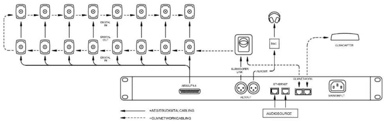
Figure 2. An example monitoring system connected with the 9401A interface
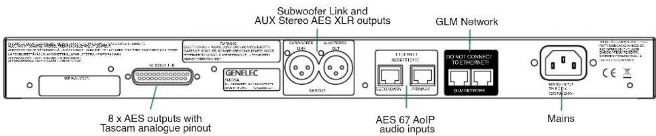
Figure 3. Connectors on the back panel of the 9401A interface
flowchart
graph TD
    A["Mac/PC"] -->|USB| B["9320A"]
    B -->|Headphone| C["GLM"]
    B -->|Measurement microphone| D["9320A"]
    D -->|GLM| E["GLM Network"]
    B -->|Aux STEREO OUT AES (XLR)| F["9401A"]
    F --> G["AES OUT 1-8 AES x 16 DB25 → 16 x XLR"]
    F --> H["SUBWOOFER LINK AES (XLR)"]
    F --> I["73xx subwoofer(s)"]
    I --> J["GLM Network"]
    B --> K["Ethernet Switch Local Area Network (LAN)"]
    K --> L["16 monitors"]
    K --> M["Audio Stream(s)"]
    K --> N["LAN"]
    N --> O["GLM Network"]
    style A fill:#f9f,stroke:#333
    style B fill:#ccf,stroke:#333
    style F fill:#cfc,stroke:#333
    style I fill:#fcc,stroke:#333
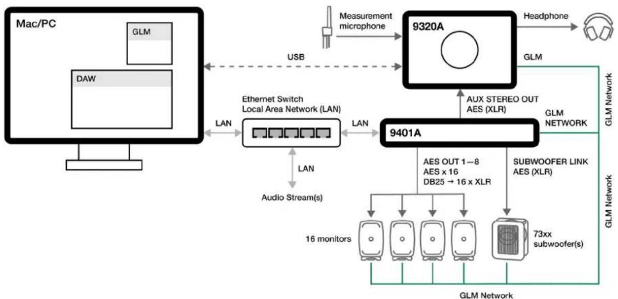
Figure 4. Example connection to computer and Genelec 9320A Reference Controller
Redundant IP Network Input
The 9401A offers two network interface connections. This enables redundant connectivity following the ST2022-7 specification. The 9401A can be connected to two separate networks, so that audio streaming is seamlessly switched over if the primary IP network is compromised. Refer to the Web interface function reference for additional information on the network interface settings.
The primary network interface is self-configuring by default. This means that the 9401A will automatically assign an IP address to itself without DHCP or DNS servers. The assigned IP address is visible in GLM. It will advertise its services and be discoverable through Bonjour, Avahi or similar implementations. For discovery, registration and control in ST2110 networks, 9401A supports the NMOS IS-04 and NMOS IS-05 interface specifications.
The secondary network interface is set in switched mode by default. IP Packets entering the primary port will be forwarded to the secondary port, allowing a second device to be connected without using a separate network switch. It can be configured using the web interface, which can be accessed through GLM. Both network interfaces support zero-configuration, DHCP or static IP operation.
The input connector of the 9401A follows the 1000Base-T standard for Gigabit Ethernet. Slower transmission speeds (10Base-T, 100Base-T) are not supported. Use of CAT 5e cabling or better is necessary.
Selection of IP switch
The 9401A is fully compatible with standard Gigabit Ethernet and IP switch technology. Genelec recommends using a managed switch. Managed IP switches offer the ability to configure, manage and monitor the local area network, typically using a web browser user interface, and this helps in creating a well working system.
The IP switches should support QoS and multicast groups. Differentiated services (DiffServ) typically implement QoS prioritization of IP traffic. DiffServ marks IP packets according to priority. In response, IP switches can prioritize media traffic to improve system performance. Differentiated services code point (DSCP) markings in the IP packet headers are sensed by the QoS capable IP switch. Multicast groups can be used to reduce traffic in large networks by forwarding data only to the devices that are set to receive it. Genelec does not endorse certain IP switch brands as the 9401A works perfectly with all high-quality standard IP switches with these capabilities. Use of 1 Gbps (Gigabit) or faster IP switches is mandatory.
Network Structure
For redundant connectivity, Genelec recommends a spine-leaf architecture. Otherwise, a star architecture is recommended. IP device ports should not be daisy chained to several IP devices. Each IP switch must have its own IP address.
The 9401A can act as an IEEE1588-2008 compliant clock source for the ST2110, AES67 or Ravenna network using the Precision Time Protocol version 2 (PTPv2). The PTP on 9401A is fully configurable through the web interface. Refer to the Web interface function reference for additional information on the PTP settings.
Audio-over-IP requires the use of a cable-based LAN network. Low-latency uncompressed audio-over-IP streaming is not feasible over WLAN.
ST2022-7 Setup
ST2022-7 support is enabled by selecting the "Multi-Interface mode" option under Network in the web interface General settings page. The two interfaces should be configured to use different IP address ranges to avoid address conflicts. Changing the interface settings requires a reboot of the
| AES67 Mode | |
| Sampling rate | 48 kHz |
| Word length | 24 bits |
| Routing | Multicast |
| Latency | 3 ms |
Table 1. Using the 9401A with Dante systems
| Indicator Colour, indication | Meaning | |
| Power switch | Solid green Power on, normal operation | |
| Blinking green GLM is adjusting 9401A | ||
| Green blink every 10 s 9401A in power save mode | ||
| No light | No power, power off | |
| Input signal indicator | Solid green Valid digital audio is detected and received | |
| No light | Valid input is not detected | |
Table 2. Front panel indicator light functions
device. The 9401A will automatically detect a ST2022-7 stream source and seamlessly switch over if one of the Ethernet links is disconnected.
Dante Compatibility
9401A can interoperate with Dante systems using the AES67 mode. This must be enabled in Dante systems that connect to 9401A to enable audio to pass. See Table 1.
Output Cabling
The AES59 standard offers a configuration to deliver 16 channels of digital audio in one direction. This configuration is used in the output DB25 connector of 9401A. The audio output in 9401A is intended for connections to monitors. The recommended cable for this connection is an 8 x XLR male fan-out cable following the AES59 pinout, also known as the Tascam analogue pinout. For example, an Avid cable type DB25-XLRM DigiSnake can be used. In addition, AES/EBU XLR-to-XLR cables are needed to extend the signals from the snake output onwards to the monitors.
The AES59 standard output connector pinout of the 9401A is shown in Figure 5. We strongly recommend that a high-quality AES/EBU digital audio cable be used.
Controls and Indicators
The 9401A's front panel features a power switch with a power-on light as well as nine
active-connection indicator lights for the AES/EBU outputs.
The 9401A is configured using Genelec Loudspeaker Manager (GLM™) software. Please refer to the 'Use With GLM Management Network' section below for details. While editing the 9401A settings in GLM, the interface's power-on light will blink continuously. A lit light indicates that the corresponding AES/EBU is available for output. If an output light is off, there is an AES/EBU data issue or there is no valid AES/EBU audio. See Table 2 for a list of indicator lights and their functions.
Troubleshooting
If there are issues with audio transmission such as cuts or latency peaks, please check the following common issues. For additional information on how to perform each step, consult the manufacturer documentation or a technician.
- Processor usage of the connected computer. If the usage is at over 75 %, there is a risk of cuts in transmission. Attempt closing unnecessary background programs.
- Power saving settings of the processor or the Ethernet adapter. Attempt disabling these settings or setting the computer to high performance mode. If using a laptop, avoid using battery power and run on mains power instead.
• Antivirus and firewall settings. Make sure
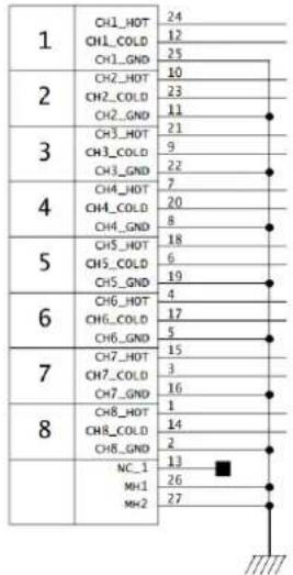
Figure 5. Digital audio output cable pin-out.
that the antivirus is not interfering with the streaming programs, and that the necessary firewall rules are set.
- Buffer length of the transmitter or receiver. Attempt increasing the buffer length or setting additional safety playout delay in the web interface general settings. If using different Ethernet adapter models in ST2022-7 mode, increasing the buffer size might be necessary to avoid cuts between switching.
- Other Ethernet or wireless adapters (Bluetooth, Wi-Fi). If these are active at the same time with the Ethernet adapter used for audio transmission, latency peaks may occur. Attempt disabling all other network and wireless adapters. An active internet connection on the streaming Ethernet interface may also cause latency peaks.
- If using an external Ethernet adapter, it is recommended to use Thunderbolt instead of USB for optimum performance.
- For the lowest latency, a network adapter with hardware PTP timestamping support should be used.
Configuration and Management Using GLM and the HTTP Web Interface
The 9401A is set up using Genelec Loudspeaker Manager GLM™ software,
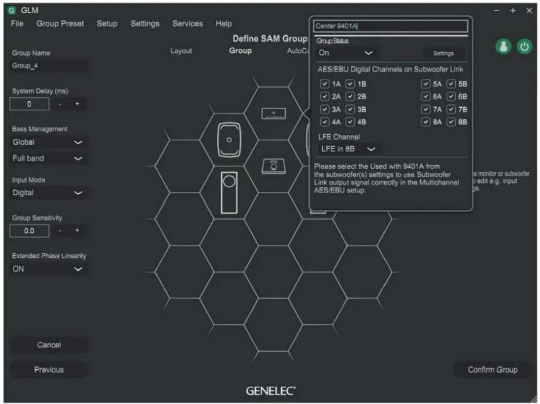
Figure 6. 9401A setup panel in GLM software
using GLM's Management Network. Advanced setup is done via an HTTP web interface. The web interface can be accessed by pressing the URL button in GLM settings for the 9401A. Refer to the Web interface function reference for additional information. More information about GLM is available in the SAM System Operating Manual.
Connection
Configuration consists of the following steps:
- Connect the IP network to the primary Ethernet network interface.
- Set up a digital audio stream in the ST2110, AES67 or Ravenna formats.
- Configure the audio source to connect to the 9410A device, for example using the web interface (Web interface function reference) or ANEMAN software.
- Connect 'AES OUT 1-8' to a fan-out cable and continue with XLR-to-XLR cables to each monitor. Please use cables intended for carrying AES/EBU
digital audio. We strongly discourage the use of standard analogue microphone cables as this may reduce system performance.
- Connect the 'SUBWOOFER LINK' output to the 'DIGITAL IN' connector on a Genelec 7300 Series subwoofer.
- Connect the 'AUX STEREO OUT' output to stereo monitors or headphones through a digital-to-analog converter and a headphone amplifier.
- Connect CAT 5 (RJ45) GLM network cables between the 9401A, every monitor and subwoofer. Finally, connect to the GLM Adapter device (see Figure 2). The connection order of the other devices is not important. Connect the GLM Adapter device to your computer via USB.
• Install and run Genelec Loudspeaker Manager (GLM) software.
All devices appear in GLM software monitor stack. Move devices from the monitor stack onto GLM's honeycomb grid, including the 9401A. You may want to drag and drop
the 9401A icon close to the subwoofer connected to it (see Figure 6).
When using multiple 9401A devices, you can identify a 9401A by clicking the 9401A icon in GLM, causing the associated 9401A device front panel power button light to blink.
Configuration
Configuration of the 9401A using GLM software has the following steps:
- Select the 'Input Signal Type' for the monitor Group to be 'AES/EBU Digital'. Then, set the group status to ON state and the 9401A devices become active.
- Select the AES/EBU outputs in the 9401A to enable them. Note that you need to configure the audio streams. (see section Setting Up Audio Streams)
- Set the 'AES/EBU Digital Input Mode' to 'Multichannel' in the 7300 series subwoofer settings.
- In the 'LFE Channel' drop-down, select the AES output and the subframe that carries the LFE channel audio.
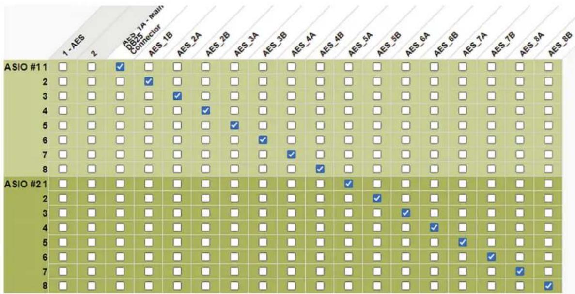
Figure 7. Audio stream setup matrix
- Select the ‘+10 dB’ setting in the subwoofer configuration if the LFE channel audio requires the 10 dB boost in the subwoofer relative to the main audio channels.
When all 9401A units in the system are set to 'Group Off' state, the 'AES/EBU Digital Input Mode' in all 7300 series subwoofers switch the AES/EBU digital stereo audio input to a standard stereo audio input.
Setting Up Audio Streams
While GLM is used for managing the LFE and sum channel output, the audio channel mapping is configured using the internal HTTP web interface or by using ANEMAN software or similar.
The web interface can be accessed through GLM, or directly from the browser using the device name. For example, if the name is "9401A_61", the web interface address is "http://9401a_61.local/advanced".
In the web interface:
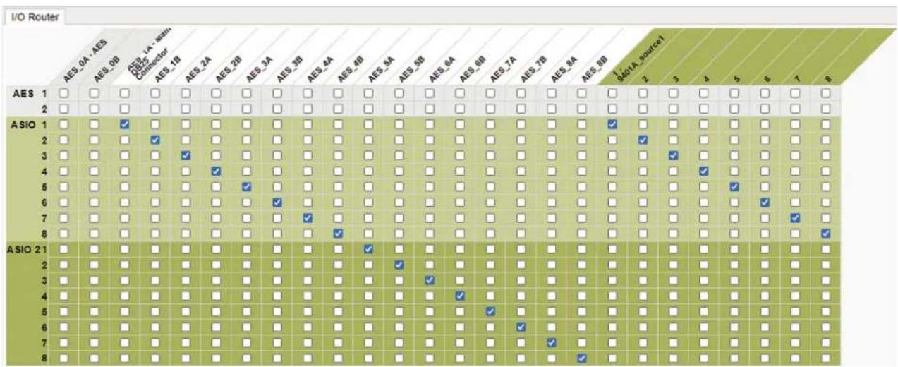
- Open the I/O router tab
- On the matrix view, inputs are shown on the rows and outputs on the columns
- Set up streams by selecting input-output pairs in the matrix
• Changes are automatically applied
The 9401A can also be used to route AoIP streams to other compatible devices. Use the Session sources tab to create a new source. Refer to the Web interface function reference for additional information on configuring a source. After the source is created, it can be routed from the I/O router tab as explained above.
Acoustic Calibration
GLM software supports automatic calibration and system alignment of the complete monitoring system.
To acoustically calibrate your setup, attach the measurement microphone included with your SAM Reference Controller or GLM Kit onto a microphone stand so that the microphone points upwards, then place the microphone at the listening position with the microphone top positioned at the listener's ear height.
Follow the steps in the GLM software to calibrate your entire system. The calibration process starts after you create a new group preset using 'File' | 'New' menu item. An existing group preset can be calibrated by selecting the 'Group Preset' | 'Calibrate' menu item.
If you wish to disconnect the computer after calibration, save the GLM calibration onto the monitors, subwoofers and 9401A interfaces in your system. The settings can be stored using the GLM software menu item 'Store' | 'Store the Current Group Settings'. Note that monitors and subwoofers have a switch that enables stored settings. This switch must be set to 'ON' for operating the system with the stored settings. After removing the GLM network cable and powering the 9401A and all monitors off and on, the stored settings are enabled. We strongly recommend using GLM software and keeping the GLM network connected to access the full flexibility of the monitoring system.
Returning to Factory Settings
GLM settings stored in a 9401A can be erased by keeping the power switch depressed for more than 10 seconds before releasing it again. This returns the 9401A to its factory settings. After this, GLM software should be used to reconfigure the 9401A.
Operating Environment
The 9401A is designed for indoor use only, and the permissible ambient room temperature is 15-35 degrees Celsius (59-95°F) with a relative humidity of 20% to 80% (noncondensing). If the 9401A has been stored or transported in a cool environment before entering a warm room, please wait between 60 minutes before unpacking it, as this will prevent harmful condensation. Sufficient cooling must be
ensured to keep the 9401A within optimal operating temperatures. No minimum clearance for ventilation is needed around the interface.
Maintenance
There are no user serviceable parts inside the 9401A. Maintenance or repair must only be performed by Genelec certified service personnel.
Guarantee
Genelec guarantees the 9401A for two years against manufacturing faults or defects that alter performance. Refer to the reseller for full sales and guarantee terms.
Safety Considerations
The 9401A has been designed in accordance with international safety standards. To ensure safe operation, the following warnings and precautions must be observed:
- Servicing and adjustment must only be performed by Genelec certified service personnel.
- The enclosure must not be opened.
- Do not use this product with a mains cable or mains outlet without a protective earth (potential-equalising) connection, as doing so may result in personal injury.
- To prevent fire or electric shock, never expose the unit to water or moisture.
- Do not place objects filled with liquid, such as vases, on or near the 9401A.
- The 9401A is never completely disconnected from mains power unless the mains cable is removed from the device or the mains outlet.
Compliance to FCC Rules
This device complies with part 15 of the FCC Rules. Operation is subject to both of the following two conditions:
- This device may not cause harmful interference.
- This device must accept any interference received, including interference that may cause undesired operation.
Note: This equipment has been tested and found to comply with the limits for a Class B digital device, pursuant to part 15 of the FCC Rules. These limits are designed to provide reasonable protection
against harmful interference in a residential installation. This equipment generates, uses, and can radiate radio frequency energy and, if not installed and used in accordance with the instructions, may cause harmful interference to radio communications. There is no guarantee that interference will not occur in a particular installation. If this equipment does cause harmful interference to radio or television reception, which can be determined by turning the equipment off and on, the user is encouraged to try and correct the interference by one or more of the following measures:
- Reorient or relocate the receiving antenna.
- Increase the separation between the equipment and receiver.
- Connect the equipment into an outlet on a circuit different from that to which the receiver is connected.
- Consult the dealer or an experienced radio/TV technician for help.
Modifications not expressly approved by the manufacturer can void the user's authority to operate the equipment under FCC rules.
| SPECIFICATIONS | |
| Description Feature | |
| Network interface RJ-45 connector for 1000BASE-T | |
| Network cable Category 5e (Cat 5e) or higher-rated Ethernet cable | |
| Number of Ethernet ports 2 | |
| Digital audio input format ST2110-30, AES67, Ravenna | |
| Digital audio input specifications ST2022-7, NMOS IS-04, NMOS IS-05 | |
| Digital audio word length Minimum 16 bits, maximum 32 bits. AES/EBU outputs maximum 24 bits | |
| Digital audio sample rate Minimum 44.1 kHz, maximum 192 kHz. Supports single-wire AES/EBU audio, does not support dual wire AES/EBU audio | |
| Digital audio output format AES/EBU (AES3-2003) Can also be used with S/P-DIF and AES3id signals when impedance converters are used | |
| Digital audio output impedance 110 ohm differential | |
| Digital audio output level 2.5 Vpp | |
| Maximum AES/EBU cable length 100 m | |
| End-to-end latency < 3 ms (dependent on buffer size) | |
| Clock synchronization Sample accurate | |
| Conversion accuracy | Bit perfect |
| Operating temperature | 15-35 C (59-95 F) |
| Weight | 2 kg (4.4 lbs) |
| DimensionsHeight:Width:Depth: | 43 mm (1 11/16 in)483 mm (19 in)105 mm (4 1/8 in) |
| Mains input voltage | 100...240 VAC (50...60 Hz) |
| Mains tolerance | +/- 10 % |
| Operating power consumption | 12 W |
| Idle power consumption | 9 W |
| ISS state power consumption | 4.5 W |
| Operating environment humidity | 10-80 % non-condensing |
| EMC compliance | FCC part 15 Class B, CE |
Web interface function reference
| General settings | |
| Device Name | |
| Device name Unique name, consists | of the model name (9401A) and serial number separated by an underscore. |
| Location Optional entry to specify the | physical location of the device (e.g., Listening Room). |
| Audio Configuration | |
| Sample rate Selects the sample rate | used for audio streaming, must be matched to the receiver/transmitter sample rate. |
| Frame size (@1FS) Number of samples | les in an Ethernet packet. Lower values provide lower latencies but require better performance from switches and streaming equipment. |
| Session Sinks Global | |
| Safety Playout Delay (@1FS) Additional delay that can be added to prevent dropouts or cuts. Value is given in samples which corresponds to the frame size (e.g., a value of 48 adds 1 ms of delay). | |
| SSM (requires IGMP v3) Source Specific Multicast, requires a router with IGMP v3 support. | |
| Network | |
| Multi-Interface mode Must be checked when using both network interfaces and for ST2022-7 support. | |
| Interface 1 / Interface 2 | |
| Link | Up with a green background: the interface is successfully connected to the network.Down: the interface is not active. |
| Name | Primary or Secondary, corresponding to the Ethernet connectors on the back of the 9401A. |
| Type | IP address assignment: Static, automatically assigned using DHCP or service discovery using Zeroconf. |
| Address | When using type Static, specifies address in IP format using dot-decimal notation. |
| Netmask | When using type Static, specifies the subnet mask using dot-decimal notation. |
| Gateway | When using type Static, specifies the router default gateway. Default route is 0.0.0.0. |
| Use as Primary Gateway Selects which interface is used as the primary transmission route in ST2022-7 mode. | |
| DNS | When using type Static, specifies the Domain Name System (DNS) server IP address. |
General settings
Device Name
9401A
This is the unique zeroconf device name. Other devices see this device name.
Location
Audio Configuration
Sample rate
48 kHz
Frame size (@1FS)
48 smpIAES67(1ms)
Session Sinks Global
Safety Playout Delay (@1FS)
0
SSM (requires IGMP v3)
□
Network
Multi-Interface mode
□
Note: must be checked for ST2022-7 support.
Interface 1
| Link | Up |
| Name | Primary |
| Type | DHCP ▼ |
| Address | 10.0.0.65 |
| Netmask | 255.255.255.0 |
| Gateway | 10.0.0.1 Use as Primary Gateway |
| DNS | 10.0.0.155 |
Note: changing the network settings require a reboot of the device.
| PTP | |
| Global | |
| Type Indicates if PTP (v1) or PTPv2 is used. | |
| Domain PTP domain, must be set to the | same value for connected master and slave devices. |
| DSCP Differentiated Services Code Point | a 6-bit priority value for Quality of Service (QoS). |
| Master | |
| Manual If not selected, uses default PTP | settings. |
| Priority1 Selects the priority used for the | Best Master Clock (BMC) selection algorithm. Lower values indicate higher priority. |
| Class Allows assigning different clocks | their own classes, each class having their own priority. |
| Accuracy The difference between the clock and UTC, in nanoseconds | |
| Priority2 Final priority in case it is not definitively decided by above criteria. Lower values indicate higher priority. | |
| GMID Unique grandmaster identifier for the clock, constructed from the device's MAC address. | |
| Slave only Forces the device to be slave only. | |
| Delay mech. Delay measurement mechanism between master or slave, End-to-End (E2E) or Peer-to-Peer (P2P). | |
| Announce PTP announcement interval in seconds. | |
| Sync PTP synchronization message interval in seconds. | |
| Status | |
| GMID Current PTP Grandmaster ID. | |
| Lock | PTP lock status. Either Unlocked, Locking or Locked. |
| Interface 1 / Interface 2 | |
| Master / Slave / Listening | Interface PTP status. Listening means the interface is not being used for synchronization. |
| GMID Grandmaster ID of the interface clock. | |
| Statistics | |
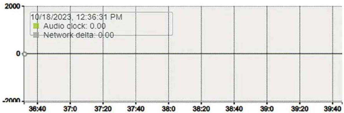
| Audio clock | Regulated difference to the current PTP master. |
| Network delta | Difference to the current PTP master, before the clock regulation algorithm. |
PTP
Global
| Type | PTPv2 |
| Domain | 0 |
| DSCP | 46 (EF) ▼ |
Master
Manual
| Priority1 | 255 |
| Class | 255 |
| Accuracy | 32 |
| Priority2 | 128 |
| GMID | 30-D6-59-FF-FE-01-B0-06 |
| Slave only | |
| Delay mech. | E2E ▼ |
| Announce | 2 sec. ▼ |
| Sync | 0.125 sec. ▼ |
Status
| GMID | 30-D6-59-FF-FE-01-B0-06 |
| Lock | Locked |
| Interface 1 | |
| Master | |
| 30-D6-59-FF-FE-01-B0-06 | |
Statistics
line
| Time | Audio clock | Network delta | | ---------- | ----------- | ------------- | | 10/18/2023 | 0.00 | 0.00 || ASIO Clock | |
| Multicast clock | |
| Auto ASIO clock is activated only on the PTP master. | |
| Address IP address and port of the multicast clock. | |
| DSCP Differentiated Services Code Point, a 6-bit priority value for Quality of Service (QoS). |
ASIO Clock
Multicast Clock
Auto
Address
239.1.219.2:4242
DSCP
34 (AF41)
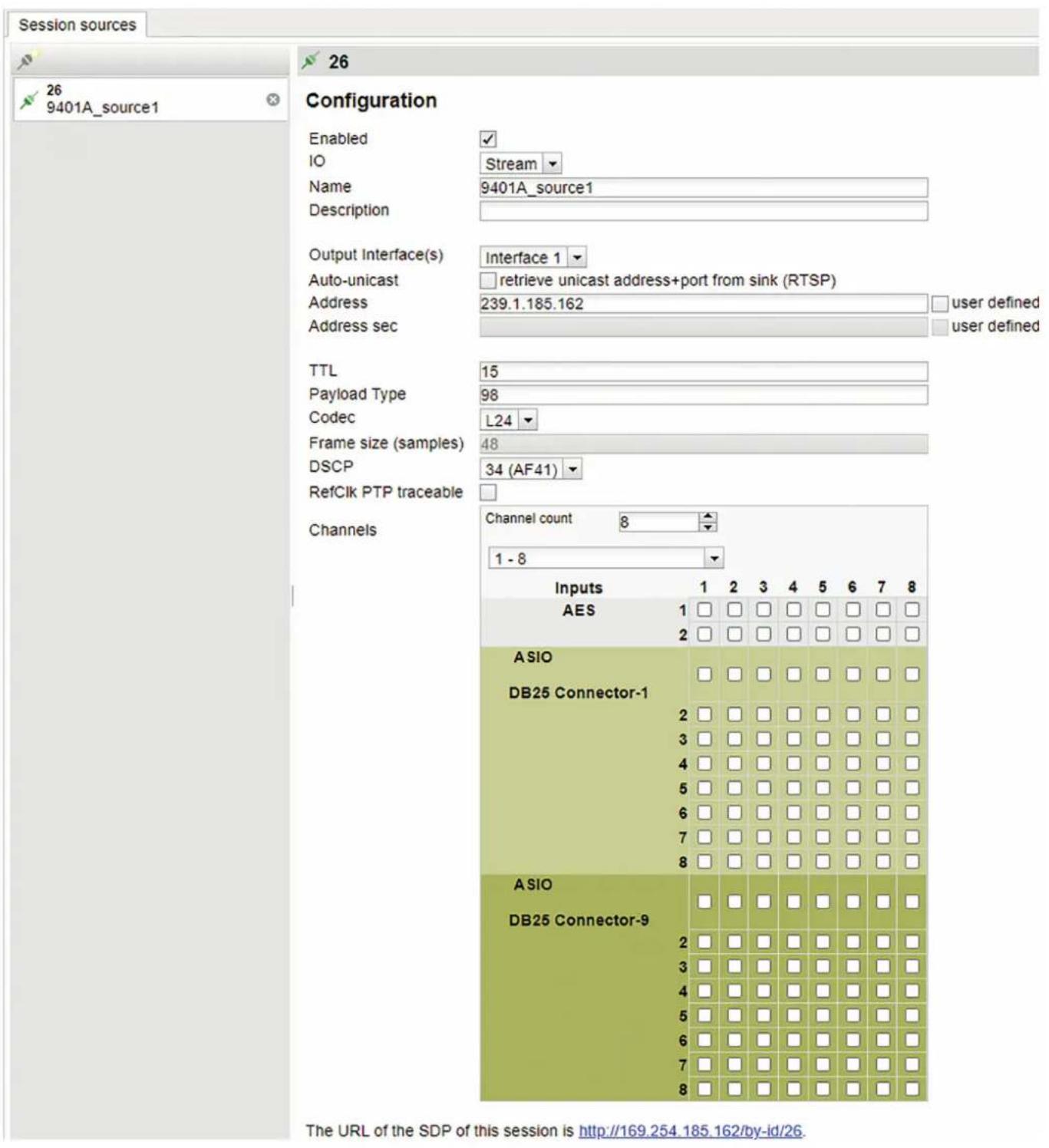
| Session sources | |
| Create session | Create a new source. |
| Configuration | |
| Enabled Enables or disables the source. | |
| IO Selects the input source. For 9401A, this is always Stream. | |
| Name Name of the source, maximum length is 63 characters. | |
| Description Optional entry. | |
| Output Interface(s) | Selects the source output. Either Interface 1, Interface 2, or Interfaces 1&2 (ST_2022-7). (Dependent on General settings). |
| Auto-unicast, retrieve unicast address+port from sink (RTSP) | Automatically retrieve the sink's IP address, for Merging Technologies devices. |
| Address Stream multicast IP address, port can also be specified separated by a colon : | |
| Address sec Stream multicast IP address for the secondary interface. | |
| TTL Time to live, number of hops the IP packet is allowed in the network. Recommended to leave at the default value. | |
| Payload Type RTP payload format. Recommended to leave at the default value. | |
| Codec Method for encoding the audio. | Either linear 16/24 bits (L16, L24) or DSD (DSD64 - DSD64_32 - DSD128 - DSD128_32 - DSD256). |
| Frame size (samples) Frame size of the source. (Dependent on General settings). | |
| DSCP | Differentiated Services Code Point, a 6-bit priority value for Quality of Service (QoS). |
| RefClk PTP traceable Allows sinks from different PTP masters to connect to the source, for example when connecting over the Internet. | |
| Channels | Number of channels in the stream.. |
| The URL of the SDP of this session is | Save the Session Description Protocol file for devices that require manual SDP. |
| Session sinks | |
| Create session sink | Create a new sink. |
| Configuration | |
| IO Selects the physical output. For 9401A, this is always Stream. | |
| Label Name of the sink. | |
| Description Optional entry. | |
| Source Selects the source, either from SAP or mDNS advertisers or manually by copying the SDP file from the source. | |
| Delay (samples) Sets the playback delay.0: Automatically set the delay.Delays between devices must be matched. | |
| Ignore refclk GMID Allows sinks from different PTP masters to connect to the source, for example when connecting over the Internet. (Dependent on the session sources settings). | |
| Ignore refclk Domain Allows sinks from different PTP clock domains to connect to the source, for example when connecting over the Internet. (Dependent on the session sources settings). | |
| Relaxed check Allows connection to a source that has less channels than the output. | |
| Channels Number of channels in the stream. | |
| Session Info | |
| Session status Yellow background and Started: the sink is attempting to connect to the source.Green background and Connected: the sink is connected to the source.Red background: the sink can't connect to the source, see the message for details. | |
| RTP status Green background and Receiving: the sink is receiving RTP (audio) packets.Red background and Muted: the stream is muted, see the Interface RTP status for details.Yellow background and Degraded: In ST2022-7 mode, one interface is not receiving RTP packets. | |
| Session name Source name from SDP file. | |
| Playout delay Total delay of the sink in samples and milliseconds. | |
| RTSP Host The source IP address. | |
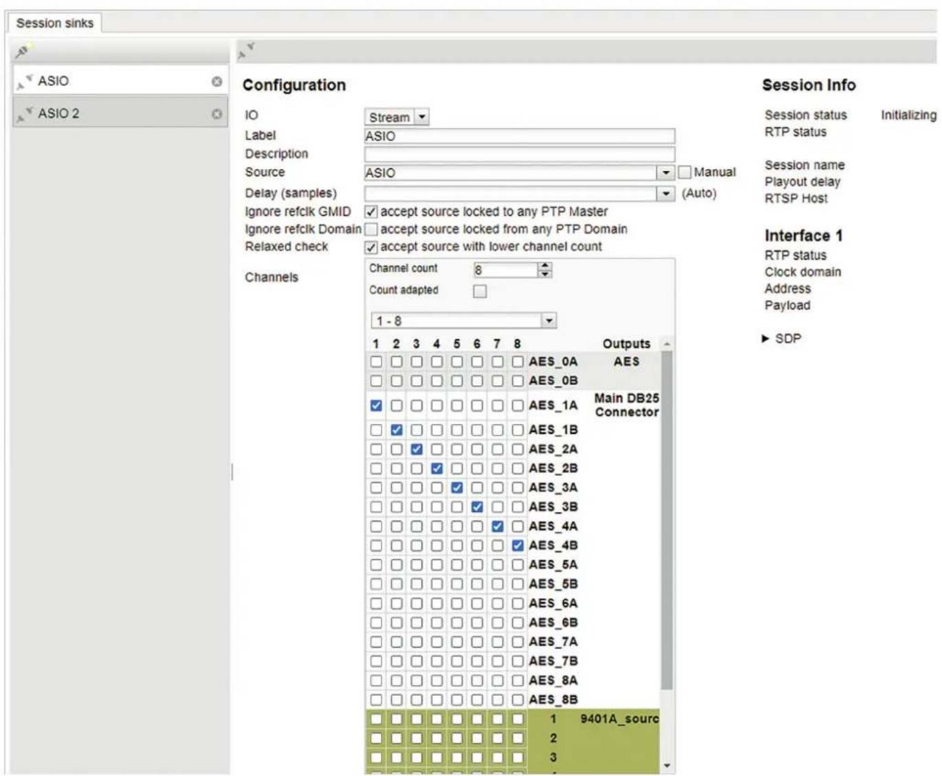
| Interface 1 / Interface 2 | |
| RTP status Information | about the incoming RTP packets.0x10: receiving RTP packets.0x20 / 0x40: stream has been muted.0x80: both interfaces are not receiving RTP packets properly (ST2022-7 mode).0x01: wrong RTP sequence id.0x02: wrong RTP SSRC.0x04: wrong RTP payload type.0x08: wrong RTP SAC. |
| Clock domain PTP clock type and domain. | |
| Address Multicast IP address of the sink. | |
| Payload The payload type, codec, sample rate and number of channels of the stream. | |
| SDP Show the SDP file of the stream. | |
| Stream status indicator Description | |
| Network offline. | |
| Network error. | |
| Network receiver error. | |
| Network started. | |
| Network receive. | |
| Network transmit | |
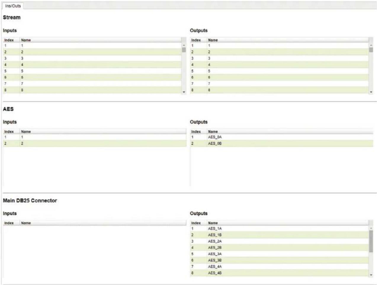
| Ins/Outs | |
| Stream | |
| Inputs AoIP stream inputs, 64 channels. | |
| Outputs AoIP stream outputs, 64 channels. | |
| AES | |
| Inputs Not physically available on the 9401A. | |
| Outputs Aux stereo out connector on the 9401A. | |
| Main DB25 Connector | |
| Inputs Not physically available on the 9401A. | |
| Outputs Main monitor outputs, 16 channels. | |
| Note: Names of the channels can be changed by double-clicking. | |
| I/O Router | |
| Rows Session sources as co | configured in the corresponding page. |
| Columns Session sinks as co | configured in the corresponding page. |
| Row-column matrix Creates | connections between source and sink channels by selecting points in the matrix. Mixing of channels is not supported. (a sink channel can receive from one source channel). |
| Statistics | |
| Sink Name of the sink being measured. | |
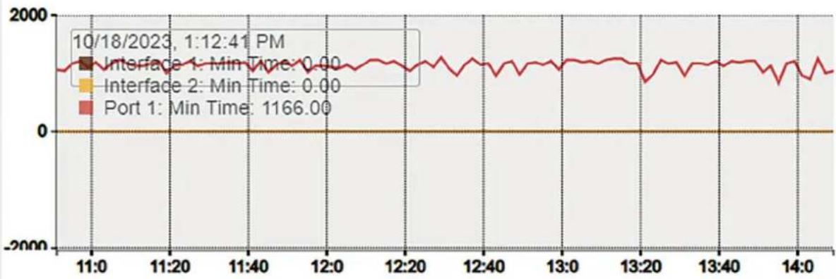
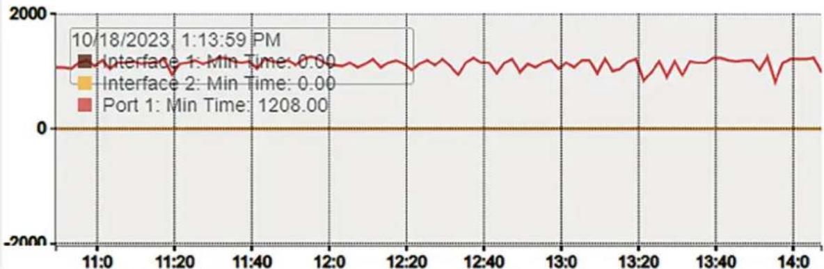
| Min The minimum latency measured from Port 1 / Port 2 to output. Does not include latency from source buffer. Resets after refreshing the web page. | |
| Max The maximum latency measured from Port 1 / Port 2 to output. Does not include latency from source buffer. Resets after refreshing the web page. | |
| Graph Displays the latency data on a graph at 2 s intervals. | |
| Note: The values can be reset by refreshing the page. | |
Statistics
Sink(27) ASIO (on Jarkko-T15)_9401A_proto4_Main DB25 Connector-1
Min: 979 / 0 [us]
Max: 1250 / 0 [us]
line
| Time | Min Time | | -------- | -------- | | 10/18/2023 | 0.00 | | 1:12:41 PM | 0.00 | | 13:00 | 0.00 | | 13:30 | 0.00 | | 14:00 | 1166.00 |Sink(28) ASIO (on Jarkko-T15)_9401A_proto4_Main DB25 Connector-9
Min: 1062 / 0 [us] [us]
Max: 1208 / 0 [us]) [us]
line
| Time | Min Time | | -------- | -------- | | 10/18/2023 | 0.00 | | 1:13:59 PM | 0.00 | | Port 1 | 1208.00 || NMOS | |
| NMOS General Settings | |
| Enable Enable or disable NMOS client. | |
| Port NMOS communication port. | |
| Flush streamer address on disable When selected, will empty streamer multicast addresses each time the streamer disabled. Allows interoperability with Nevion. | |
| Set UUID from Names When selected, will set the Universally Unique Identifier from the source name. Source names must be unique in this case. | |
| Configure Registration Server | |
| Mode NMOS server communication mode. Either Static Address, Search Domain by providing a network domain, or automatic discovery by mDNS. | |
| Address | When Mode is set to Static Address, specifies the NMOS server IP address. |
| Search domain | When Mode is set to Search Domain, specifies the DNS domain to search in. |
| Registration Server | |
| Server Name NMOS server name provided by the server via DNS or mDNS. | |
| Host NMOS host name provided by the server via DNS or mDNS. | |
| Address NMOS server address. | |
| Port NMOS server port. | |
| Registered True if registration with the server is successful. | |
| Note: The NMOS must be disabled to change the settings. | |
NMOS
NMOS
NMOS General Settings
Enable

Port
1936
Flush streamer address on disable

Set UUID from Names (needs a device restart when changing node name)

Configure Registration Server
Mode
mDNS
Address

Search domain
aoip.genelec.local
Suggested:
Registration Server
Server Name
Host
Address
Port
Registered
false
| System | |
| Build Number | |
| Build Number Currently installed firmware version. | |
| Configuration file | |
| Download Save device configuration to a file. | |
| Upload Save device configuration from a file. | |
| Commands | |
| Reboot Reboot the AoIP module. For applying settings. | |
| Reboot to Factory Reboot the AoIP module to factory default values. | |
| Restart Fully restart the AoIP module. | |
| Save Save the current configuration. | |
| Debug | |
| Get Report Generates a debug report. | |
| Get Device Status Display the device status. | |
| Get Device Engine Status Display the device engine status. | |
System
Build Number
1.6.0b56768
Configuration file
Download
Upload
Commands
Reboot
Reboot to Factory
Restart
Save
Debug
Get Report
Get Device Status
Get Device Engine Status
| Static top panel | |
| Device selection drop-down menu When multiple devices exist in the same network, can be used to change between their WebApps. | |
| Vendor Device vendor name. (Genelec) | |
| Product Device name. (9401A) | |
| Serial Serial number of the device. | |
| Identify Me When using multiple devices, can be used to identify which device is being configured. When checked, the 9401A flashes its power button LED. | |

RAVENNA
AES67
now!

9401A


Vendor Genelec
Product 9401A
Serial
Identify Me □
GENELEC®
the sonic reference
Genelec Document D0207R001. Copyright Genelec Oy 4.2024. All data subject to change without prior notice
www.genelec.com
GENELEC®
International enquiries:
Genelec, Olvitie 5
FIN-74100, Iisalmi, Finland
Phone +358 17 83BB1
Fax +358 17 812 267
Email genelec@genelec.com
In the U.S. please contact:
Genelec, Inc., 7 Tech Circle
Natick, MA 01760, USA
In China please contact:
Beijing Genelec Audio Co.Ltd
Room 101, Building B33,
Universal Business Park,
No.10 Jiuxianqiao Road,
Chaoyang District,
100015 Beijing, China
Phone +86 (10) 5823 2014
+86 400 700 1978
Email genelec.china@genelec.com
In Japan, please contact:
Genelec Japan Inc.
2-22-21 Akasaka, Minato-ku
07-0052, Tokyo
Phone +81-3-6441-0591
genelec.japan@genelec.com
Email genelec.japan@genelec.com
In Sweden please contact
Genelec Sverige
Tureholmsvägen 12
125 35 Älvsjö
Sweden
Phone +46 8 449 5220
Email sweden@genelec.com
- Genelec 9401A Multichannel Audio-Over-IP Interface
- Introduction
- Installation
- Connections
- Redundant IP Network Input
- Selection of IP switch
- Network Structure
- ST2022-7 Setup
- Dante Compatibility
- Output Cabling
- Controls and Indicators
- Troubleshooting
- Configuration and Management Using GLM and the HTTP Web Interface
- Connection
- Configuration
- Setting Up Audio Streams
- Acoustic Calibration
- Returning to Factory Settings
- Operating Environment
- Maintenance
- Guarantee
- Safety Considerations
- Compliance to FCC Rules
- Device Name
- Audio Configuration
- Session Sinks Global
- Network
- Multicast Clock
- Statistics
- NMOS
- NMOS General Settings
- Configure Registration Server
- Registration Server
- Build Number
- Configuration file
- Commands
- Debug
Brand : GENELEC
Model : 9401A
Category : Uncategorized