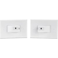
ECM S10 - Detection sensor Extron - Free user manual and instructions
Find the device manual for free ECM S10 Extron in PDF.


| Product Type | AV Control Module |
| Brand | Extron |
| Model | ECM S10 |
| Dimensions | 100 x 50 x 25 mm |
| Weight | 0.15 kg |
| Power Supply | 12V DC, 500 mA |
| Power Consumption | 6W |
| Inputs | 1x RS-232, 1x Ethernet |
| Outputs | 1x IR, 1x Relay |
| Control Protocol | TCP/IP, UDP |
| Mounting | Rack mount (optional bracket) |
| Operating Temperature | 0°C to 50°C |
| Storage Temperature | -20°C to 70°C |
| Humidity | 10% to 90% non-condensing |
| Main Functions | Device control, automation, scheduling |
| Cleaning | Dry cloth, no liquids |
| Safety | CE, FCC certified |
| Repairability | Modular design, replaceable power supply |
| Warranty | 3 years limited |
| Software Support | Extron PCS, Global Configurator |
Frequently Asked Questions - ECM S10 Extron
User questions about ECM S10 Extron
0 question about this device. Answer the ones you know or ask your own.
Ask a new question about this device
Download the instructions for your Detection sensor in PDF format for free! Find your manual ECM S10 - Extron and take your electronic device back in hand. On this page are published all the documents necessary for the use of your device. ECM S10 by Extron.
USER MANUAL ECM S10 Extron
ECM S10 Partition Sensor • Setup Guide
ECM S10 is a pollution degree 2 product with a rated impulse voltage of 330 V. Construction of Control is defined as "Independently Mounted". The purpose of the control is considered as an "Operating Control" with Type 1 Action.
The Extron ECM S10 is an eBUS ^® compatible partition sensor. The sensor consists of a transmitter and receiver pair, which are mounted, face down, in the ceiling on either side of a moveable room partition. The receiver is mounted up to 10 feet (3 m) away from the transmitter and in direct line of sight. When the partition is open, the receiver detects the IR signal from the transmitter. When the partition is closed, the IR signal from the transmitter is blocked and the receiver can no longer detect a signal.
The control signal indicating whether the partition is open or closed can be sent through the eBUS port. Alternatively, it can be sent through the digital output port, which allows communication with Extron IPCP control processors, Extron legacy control products, or third-party controllers that have digital I/O ports.
Multiple ECM S10 partition sensors can be connected to a single control processor. If the control signal is sent via eBUS, up to eight partition sensors can be connected to the IPCP control processor.
NOTE: Extron IPCP control processors are the only control processors that have an eBUS port.
If the control signal is sent via the digital port, the number of partition sensors is limited only by the number of digital I/O ports available on an Extron or third-party control processor.
The receiver is powered through the eBUS port. The transmitter is powered by a 14 VDC cable connected to the receiver. The transmitter does not have an eBUS port.
Panel Features
Rear Panel

Figure 1. Rear Panel Features of ECM S10 Transmitter (left) and Receiver (right)
A Decorator Style Faceplate Cover Mounting Location (2) — Used to attach the oversized 1-gang decorator style cover.
B US 1-gang Mounting Slots (2) — Used to mount the device to any standard US 1-gang junction box. The slots allow minor alignment adjustments.
© EU and MK 1-gang Mounting Slots (2) — Used to mount the device to any standard EU or MK 1-gang junction box. The slots allow minor alignment adjustments.
D Transmitter Power Input — A 12-inch (305 mm) pigtail, terminated with a two-pole captive screw connector accepts power from the receiver power output (see G, below). A separate cable, connecting the pigtail to the receiver, must be provided by the user.
eBUS Status LEDs — The ECM S10 receiver has yellow, red, and green LEDs that provide diagnostic information about the connection, communication, and power status of the panels. For more information about how the LEDs are used for troubleshooting see Step 5 — Testing and Troubleshooting the System on page 12.
eBUS Port — This four-pole captive screw connector provides power to the ECM S10 receiver and can also provide communication between the ECM S10 and an Extron IPCP control processor.
NOTES:
- If the control signal is sent to the control processor by eBUS, cables are connected to all four poles (see Step 2 — Connecting Cables to the Units on page 6).
- If the control signal is sent to the control processor by digital output port, cables are connected to the +V and G poles only (see Step 2 — Connecting Cables to the Units).
G Receiver Power Output — This two-pole captive screw connector provides 14 VDC to the transmitter.
Digital Output Port — If the control signal is sent to the control processor by digital output, connect this two-pole captive screw connector to a Digital I/O port on a control processor.
Front Panel


① Transmitter with sensor cover
② Receiver with sensor cover
③ Receiver with cover removed.
Figure 2. Front Panel Features of ECM S10
A IR Signal Source — The transmitter emits an IR signal through this slot in the cover.
B IR Signal Detector — The receiver detects the IR signal from the transmitter, when it passes through this slot in the cover.
Sensor Status LEDs — The transmitter has one red LED. The receiver has one amber and one green LED. These provide feedback about the power and alignment status:
| Sensor Set to Normally Open (D) | Digital OutputTransmitter | |||
| Red LED Amber | LED Green LED | |||
| Sensors aligned and partition open | ON OFF ON | open/Logic High | ||
| Partition closed | ON ON ON | Closed/Logic Low/Ground | ||
| Sensors not aligned and partition open | ON ON ON | Closed/Logic Low/Ground | ||
If the red transmitter LED is off, the transmitter is not receiving power.
If the green receiver sensor LED is off, the receiver is not receiving power.
Removable Sensor Cover — Both the transmitter and receiver have sensor covers. They are removed by gently pressing the sides of the sensor cover to free the catches on both sides from the slots in the metal mounting plate. The cover can then be pulled straight out.
Removing the cover from the receiver provides access to the BUS ID DIP switches, the sensitivity adjustment control, the sensor setting control, and Reset button.
E Sensitivity adjustment — By default, the sensitivity of the detector in the receiver is set to maximum. Extron recommends that it remains at this setting.
F Sensor Setting — By default, this is set to D (normally open). If required, use a small, flat-bladed screwdriver to turn the setting to L (normally closed).
BUS ID DIP Switches — Up to eight partition sensors configured for eBUS operation can be connected to one control processor. Each eBUS device connected to the same control processor must have a unique BUS ID, which is set using the DIP switches (see Step 3 — Setting the BUS ID Addresses on page 9).
Reset Button — If required, press this recessed button to reset the firmware to the factory installed version.
To reset the firmware
- Disconnect the eBUS cable that is providing power.
- Press and hold down the Reset button and, while holding down the Reset button, reconnect eBUS cable.
- Release the Reset button 1 second after reconnecting power. When the eBUS Connection Status LED lights, the reset process is complete.
If the reset is carried out while the ECM S10 is sending the partition status signal via I/O ports (no control signal via eBUS), the firmware is reset to the factory default. However, if the reset is carried out while the partition status signal is sent via eBUS, the firmware is initially reset to the factory default but the IPCP control processor may then push a more recent version of the firmware to the ECM S10.
Installing the ECM S10 Partition Sensor
The ECM S10 can transmit information about the partition status (open or closed) in any of the following ways:
• Via eBUS port to an Extron control processor
• Via digital output port to an Extron control processor
• Via digital output port to a third-party control processor
Installation Overview
How the partition status signal is sent to the control processor determines how the ECM S10 receiver is connected to the control processor. This, in turn, affects how the sensor is installed. The following sections describe:
• Before You Start (see page 3)
• Downloading Software (see page 3)
• Considerations for Placing the ECM S10 (see page 4)
• Installation (see page 5)
- Step 1 – Installing the Junction Boxes (see page 5)
-
Step 2 — Connecting Cables to the Units (see page 6)
• Partition status signal via eBUS (see page 7)
• Partition status signal via I/O Ports (see page 8) -
Step 3 — Setting the BUS ID Addresses (see page 9) only for Control Signal via eBUS
- Step 4 – Configuring the System (see page 12)
• Step 5 — Testing and Troubleshooting the System (see page 12)
• Step 6 — Mounting the Transmitter and Receiver (see page 13)
• Step 7 — Aligning the Transmitter and Receiver (see page 13)
Before You Start
Downloading Software
If you are sending the partition status signal via eBUS or if you are using digital output ports connected to an Extron IPCP Pro control processor, download the latest versions of Extron Global Configurator Plus and Professional or Global Scripter. You can use Global Configurator to configure the system or Global Scripter to program the system.
If you are using digital output ports connected to other Extron control products, download Global Configurator 3.0.
See the appropriate help file for information about using the software.
To download the software:
- Go to www.extron.com.
- Click Download (see figure 3, ①).
- Click Software ( ②).

Figure 3. Downloading Software
ECM S10 Partition Sensor • Setup Guide (Continued)
The Download Center Software page opens:

Figure 4. Download Center Software Page
- If the software appears at the top of the page, click on the product (see figure 4, ①), which takes you to the product page on the Extron web site. This provides further information about the product. Click Download and follow the on-screen instructions to download the software.
- If you do not see the product, click the < or > arrows (②) to see other options.
- If the product is not listed in the top section of the page, click the initial letter of the software product name (③). Software products with that initial letter are listed at the bottom of the page (④).
- Click Download (5) and follow the on-screen instructions to download the software.
Considerations for Placing the ECM S10
The following conditions influence where the ECM S10 can be installed:
• The transmitter and receiver must be placed on opposite sides of the moveable partition wall.
- The transmitter and receiver are designed to mount face down into junction boxes on the ceiling. The ECM S10 units can mount to a 1-gang US junction box, a 1-gang EU junction box, or a 1-gang MK junction box.
- When the partition is closed, the receiver must be unable to detect the IR signal sent by the transmitter.
- When the partition is open, the receiver must be able to detect the IR signal sent by the transmitter.
- The transmitter and receiver must be aligned so that the receiver is within line of sight of the transmitter (the detector of the receiver cannot be more than 2.5° from the center line of the signal from the transmitter).
- The distance between the transmitter and receiver must not exceed 10 feet (3 meters).
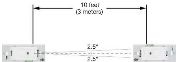
Figure 5. ECM S10 Mounting Requirements
Installation
Step 1 — Installing the Junction Boxes
ATTENTION:
Once the precise locations for the transmitter and receiver have been determined (see Considerations for Placing the ECM S10 on the previous page), install two 1-gang junction boxes (US, EU, or MK) in the ceiling. One junction box is for the receiver and one is for the transmitter (see figure 6).
The junction boxes must be aligned so that the tops and bottoms face each other, on either side of the room partition. Ensure the junction boxes are aligned so that, when the partition is open, the signal from the transmitter can be detected by the receiver.
The distance between the two boxes must not exceed 10 feet (3 meters).
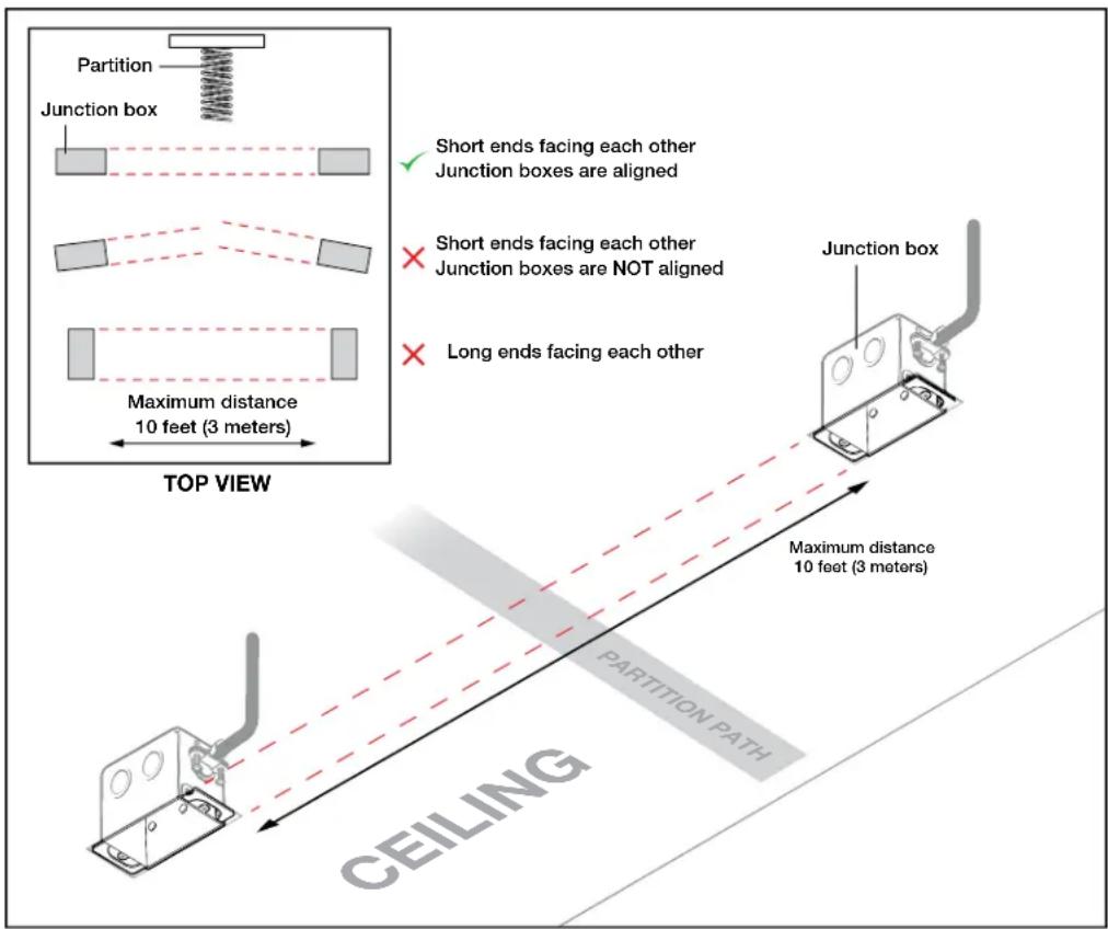
Figure 6. Installing the Junction Boxes
NOTES:
- For the installation to meet UL requirements and to comply with National Electrical Code (NEC), the ECM S10 must be installed in a UL Listed junction box (not included with the ECM S10).
- The junction boxes must be purchased separately by the end user or installer.
- The junction boxes must be installed by following the instructions provided by the manufacturer.
The transmitter and receiver should be connected, using a plenum-rated serial control cable. If the cable is not plenum-rated, it must be contained within a conduit run between the two junction boxes.
Step 2 — Connecting Cables to the Units
The receiver can be powered by an eBUS connection to an Extron IPCP control processor, distribution hub, an active distribution hub (such as the PS 1220 EB), or a 12 VDC power supply.
The transmitter is powered by a 14 VDC power cable from the receiver.
Do not connect power to either unit until you have read these Attention notifications.
ATTENTION:
- Connect up to eight eBUS devices for each IPCP Pro control processor.
- Wire the connectors in the same way at both ends.
- Do not exceed a total of 1000 feet (305 meters) of cable for connections between the IPCP Pro and all the eBUS panels and devices. This is true even if the signal is not carried by the eBUS connection.
- Do NOT power an ECM S10 from more than one power source. Power can be provided by an IPCP Pro control processor, a PS 1220EB power supply, or an Extron 12 VDC power supply. If more than one power source is used in a system, make sure that the devices powered by the first source are isolated from the devices powered by the second source by disconnecting the +V pin of the first source.
Partition status signal via eBUS
- Connect the receiver to a control processor or power supply using a standard eBUS cable. Before powering on the control processor, read the Attention notifications on the previous page. The four connectors are:
• +V — Carries 12 VDC power from the controller, active hub, or power supply
• +S — Carries the positive data signal
- -S — Carries the negative data signal
• G — Ground
Extron STP20-2/1000 or STP20-2P/1000 cable is recommended for eBUS connections.

Figure 7. Wiring When the Partition Status Signal is Carried by eBUS
- Connect the 14 VDC output on the receiver (see figure 1, G, on page 1) to the 14 VDC input on the transmitter (D). The cable (not provided) should be run between the two junction boxes. If possible, use a plenum-rated serial control cable (for example Extron STP 20 or STP 20-2 cable). If the cable is not plenum-rated, it must be contained within a conduit run between the two junction boxes.
Figure 8 shows how the system is cabled when the partition status signal is carried by eBUS.
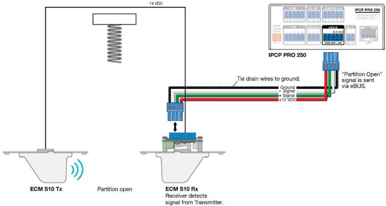
Figure 8. Connecting the Cables when the Partition Status Signal is Carried by eBUS
NOTE: Power to the receiver (red and black wires) can come from the IPCP control processor, powered distribution hub, or a power supply. If power comes from a power supply, the red and black wires must be disconnected from the control processor.
ECM S10 Partition Sensor • Setup Guide (Continued)
Partition status signal via I/O Ports
- Connect the receiver to a control processor or power supply using a modified eBUS cable. Before powering on the control processor, read the Attention notifications on page 6. Use only the two following connectors:
• +V — carries 12 VDC power from the controller, active hub, or power supply
• G - ground

Figure 9. Wiring when the Partition Status Signal is Carried by Digital Output
- If you use the eBUS connector for power only, you must connect the receiver digital output port to a digital I/O port on a control device.
- Connect the 14 VDC output on the receiver (see figure 1, G, on page 1) to the 14 VDC input on the transmitter (D). The cable (not provided) should be run between the two junction boxes. If possible, use a plenum-rated serial control cable (for example Extron STP 20 or STP 20-2 cable). If the cable is not plenum-rated, it should be contained within a conduit run between the two junction boxes.
Figure 10 shows how the system is cabled when the partition status signal is carried via the digital output ports.
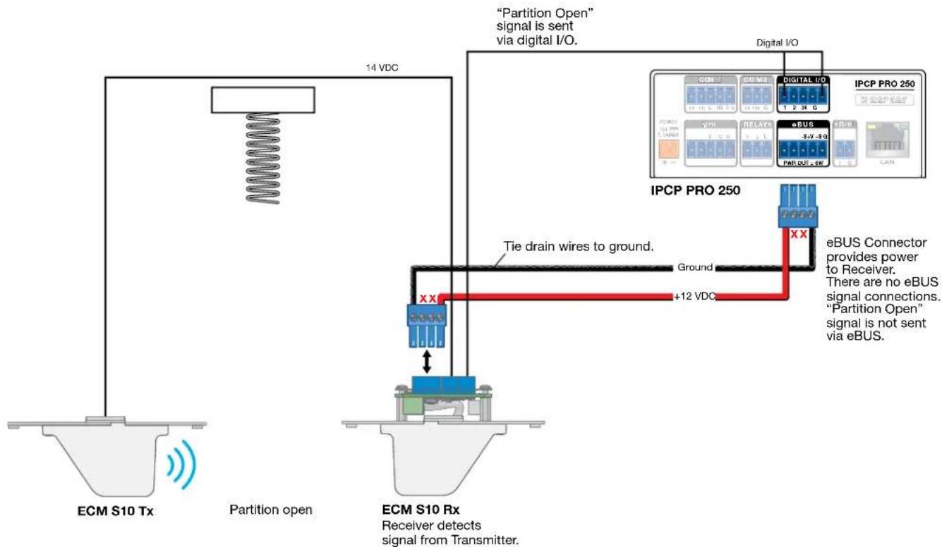
flowchart
graph TD
    A["ECM S10 Tx"] --> B["Partition open"]
    B --> C["ECM S10 Rx"]
    C --> D[""Partition Open" signal is sent via digital I/O."]
    D --> E["Digital I/O"]
    E --> F["IPC P PRO 250"]
    F --> G["eBUS Connector provides power to Receiver. There are no eBUS signal connections. "Partition Open" signal is not sent via eBUS."]
    C --> H["Tie drain wires to ground."]
    H --> I["Ground"]
    I --> J["+12 VDC"]
    J --> K["ECM S10 Rx"]
    style A fill:#f9f,stroke:#333
    style B fill:#ccf,stroke:#333
    style C fill:#cfc,stroke:#333
    style D fill:#fcc,stroke:#333
    style E fill:#cff,stroke:#333
    style F fill:#ffc,stroke:#333
    style G fill:#fcc,stroke:#333
    style H fill:#ffc,stroke:#333
    style I fill:#fcc,stroke:#333
    style J fill:#cff,stroke:#333
    style K fill:#fcc,stroke:#333
Figure 10. ECM S10 Sending the Partition Status Signal by Digital Output Port
NOTE: Power to the receiver (red and black wires) can come from the IPCP control processor or a power supply. If power comes from a power supply, the eBUS cable connects to the power supply and NOT to the control processor.
Step 3 — Setting the BUS ID Addresses
This step is required if the control signal is passed via eBUS. If the signal is passed by I/O ports, go to Step 4 — Configuring the System (see page 12).
Up to eight eBUS devices can be connected to one IPCP control processor. In order for the control processor to be successfully configured, each eBUS device connected to the same control processor must have a unique six-bit, BUS ID, which is set with the DIP switch assembly on the front panel of the ECM S10 (figure 2, G, on page 2). If two or more modules have the same BUS ID, address conflicts may cause one or more of the panels to not be recognized by the IPCP Pro control processor. If there is an address conflict, the red status LED (see figure 1, E, on page 1) lights solidly (see Step 5 — Testing and Troubleshooting the System on page 12).
Various combinations of the six DIP switches being set to On or Off provide 64 addresses: 0 is a reserved eBUS ID and the configurable eBUS ID range is 1 through 63 (see the table starting on the next page in Setting BUS ID numbers). The section below shows an example of binary to decimal conversion.
eBUS ID Setup
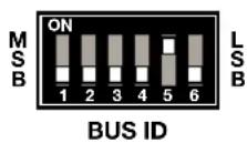

| DIP Switch | ||||||
| 1 | 2 | 3 | 4 | 5 | 6 | |
| Position | Off | Off | Off | Off | On | Off |
| Decimal | 2^5=32 | 2^4=16 | 2^3=8 | 2^2=4 | 2^1=2 | 2^0=1 |
Figure 11. eBUS ID Setup
Add the decimal numbers for each of the DIP switches that are set to On to obtain the address of the eBUS device. In figure 11, only DIP switch #5 is on and the rest are off, which means the address for the device in figure 11 is 2 (0+0+0+0+2+0).
NOTES:
- Any address can be used except address 0 (binary: 000000), which is reserved (as the address of the controller) and may not be used.
- Switch 1 (on the left) is the highest value (32, the most significant bit) and is labelled MSB.
- Switch 6 (on the right) is the lowest value (1, the least significant bit) and is labelled LSB.
• Up = on = 1, Down = off = 0
The factory default address for the ECM S10 is 20 (BUS ID = 010100). The ID can be changed to any valid value. The table on the following two pages shows the BUS ID DIP switch settings for all 64 possible addresses.
Setting BUS ID numbers
In the table below, a DIP switch setting shown as is equivalent to Off. A DIP switch setting shown as 1 is equivalent to On.
NOTE: The ID number 0 (switch setting 000000) is reserved for the IPCP control processor and cannot be used by an eBUS device.
| DIP Switch Setting | Decimal Value | DIP Switch Setting | Decimal Value | ||||||||||||||||||||||
| 1 | 2 | 3 | 4 | 5 | 6 | 1 | 2 | 3 | 4 | 5 | 6 | ||||||||||||||
| MSB |  | LSB | 00 | 00 | 0 | 0 | MSB | ON1 2 3 4 5 6 | LSB | 00 | 11 | 1 | 15 | ||||||||||||
| MSB | 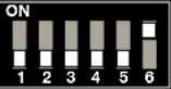 | LSB | 00 | 00 | 1 | 1 | MSB | ON1 2 3 4 5 6 | LSB | 01 | 00 | 0 | 16 | ||||||||||||
| MSB |  | LSB | 00 | 01 | 0 | 2 | MSB | ON1 2 3 4 5 6 | LSB | 01 | 00 | 1 | 17 | ||||||||||||
| MSB |  | LSB | 00 | 01 | 1 | 3 | MSB | ON1 2 3 4 5 6 | LSB | 01 | 01 | 0 | 18 | ||||||||||||
| MSB |  | LSB | 00 | 01 | 0 | 4 | MSB | ON1 2 3 4 5 6 | LSB | 01 | 01 | 1 | 19 | ||||||||||||
| MSB |  | LSB | 00 | 01 | 1 | 5 | MSB | ON1 2 3 4 5 6 | LSB | 01 | 01 | 0 | 20 | ||||||||||||
| MSB |  | LSB | 00 | 01 | 0 | 6 | MSB | ON1 2 3 4 5 6 | LSB | 01 | 01 | 1 | 21 | ||||||||||||
| MSB |  | LSB | 00 | 01 | 1 | 7 | MSB | ON1 2 3 4 5 6 | LSB | 01 | 01 | 0 | 22 | ||||||||||||
| MSB |  | LSB | 00 | 10 | 0 | 8 | MSB | ON1 2 3 4 5 6 | LSB | 01 | 01 | 1 | 23 | ||||||||||||
| MSB |  | LSB | 00 | 10 | 1 | 9 | MSB | ON1 2 3 4 5 6 | LSB | 01 | 10 | 0 | 24 | ||||||||||||
| MSB |  | LSB | 00 | 10 | 0 | 10 | MSB | ON1 2 3 4 5 6 | LSB | 01 | 10 | 1 | 25 | ||||||||||||
| MSB |  | LSB | 00 | 10 | 1 | 11 | MSB | ON1 2 3 4 5 6 | LSB | 01 | 10 | 0 | 26 | ||||||||||||
| MSB | 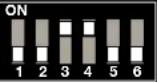 | LSB | 00 | 11 | 0 | 12 | MSB | ON1 2 3 4 5 6 | LSB | 01 | 10 | 1 | 27 | ||||||||||||
| MSB | 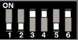 | LSB | 00 | 11 | 1 | 13 | MSB | ON1 2 3 4 5 6 | LSB | 01 | 11 | 0 | 28 | ||||||||||||
| MSB |  | LSB | 00 | 11 | 0 | 14 | MSB | ON1 2 3 4 5 6 | LSB | 01 | 11 | 1 | 29 | ||||||||||||
| MSB | 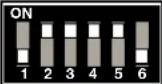 | LSB | 01 | 11 | 0 | 30 | MSB |  | LSB | 10 | 11 | 1 | 47 | ||||||||||||
| MSB |  | LSB | 01 | 11 | 1 | 31 | MSB |  | LSB | 11 | 00 | 0 | 48 | ||||||||||||
| MSB |  | LSB | 10 | 00 | 0 | 32 | MSB |  | LSB | 11 | 00 | 1 | 49 | ||||||||||||
| MSB |  | LSB | 10 | 00 | 1 | 33 | MSB |  | LSB | 11 | 00 | 1 | 0 | 50 | |||||||||||
| MSB |  | LSB | 10 | 00 | 1 | 0 | 34 | MSB | 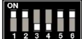 | LSB | 11 | 00 | 1 | 1 | 51 | ||||||||||
| MSB | 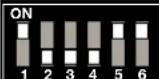 | LSB | 10 | 00 | 1 | 1 | 35 | MSB |  | LSB | 11 | 01 | 0 | 0 | 52 | ||||||||||
| MSB |  | LSB | 10 | 01 | 0 | 0 | 36 | MSB |  | LSB | 11 | 01 | 0 | 1 | 53 | ||||||||||
| MSB |  | LSB | 10 | 01 | 0 | 1 | 37 | MSB | 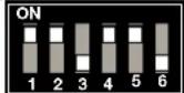 | LSB | 11 | 01 | 1 | 0 | 54 | ||||||||||
| MSB |  | LSB | 10 | 01 | 1 | 0 | 38 | MSB |  | LSB | 11 | 01 | 1 | 1 | 55 | ||||||||||
| MSB |  | LSB | 10 | 01 | 1 | 1 | 39 | MSB |  | LSB | 11 | 10 | 0 | 0 | 56 | ||||||||||
| MSB |  | LSB | 10 | 10 | 0 | 0 | 40 | MSB |  | LSB | 11 | 10 | 0 | 1 | 57 | ||||||||||
| MSB | 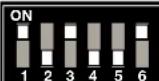 | LSB | 10 | 10 | 0 | 1 | 41 | MSB | 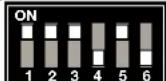 | LSB | 11 | 10 | 1 | 0 | 58 | ||||||||||
| MSB | 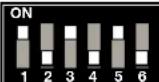 | LSB | 10 | 10 | 1 | 0 | 42 | MSB | 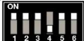 | LSB | 11 | 10 | 1 | 1 | 59 | ||||||||||
| MSB |  | LSB | 10 | 10 | 1 | 1 | 43 | MSB |  | LSB | 11 | 11 | 0 | 0 | 60 | ||||||||||
| MSB | 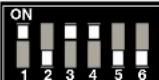 | LSB | 10 | 11 | 0 | 0 | 44 | MSB | 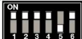 | LSB | 11 | 11 | 0 | 1 | 61 | ||||||||||
| MSB |  | LSB | 10 | 11 | 0 | 1 | 45 | MSB | 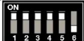 | LSB | 11 | 11 | 0 | 0 | 62 | ||||||||||
| MSB | 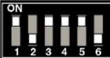 | LSB | 10 | 11 | 1 | 0 | 46 | MSB |  | LSB | 11 | 11 | 1 | 1 | 63 | ||||||||||
Step 4 — Configuring the System
The system must be configured to respond to the eBUS partition status signal or the digital output Logic High (partition open) or Logic Low (partition closed) signal in an appropriate manner.
By this stage, the junction boxes should be installed, and the transmitter and receiver should be connected by a power cable.
- If the partition status signal is sent via eBUS, each device connected to the same IPCP control processor must have a unique six-bit BUS ID, which is set with the BUS ID DIP switch assembly (see Step 3 — Setting the BUS ID Addresses on page 9). The DIP switches are accessed by removing the cover from the front panel of the receiver (see figure 2, G, on page 2). If two or more modules connected to the same IPCP Pro control processor have the same BUS ID, address conflicts may prevent the ECM S10 devices from being recognized by the control processor.
- If the partition status signal is sent via eBUS, you can configure the system using Global Configurator Plus and Professional or program the system using Global Scripter (see the help file for the software for more information about setting up an eBUS system).
- If the partition status signal is sent via the digital output port to an Extron IPCP Pro control processor, Global Configurator Plus and Professional or Global Scripter are still required to configure the system.
- If the partition status signal is sent via the digital output port to an Extron IPLink (non-Pro) control processor, use Global Configurator 3.0 or later to configure the system (see the Global Configurator Help File).
- If the partition status signal is sent via the digital output port to a third-party controller, use the control system software recommended for that controller.
Step 5 — Testing and Troubleshooting the System
After configuring the system, test that it is working correctly. Test the system before mounting the transmitter and receiver into the junction boxes because, after they are mounted, the three status LEDs on the rear panel of the receiver are inaccessible.
Ensure that the receiver responds to signals from the transmitter
-
Connect power and check that:
-
The green sensor LED on the receiver front panel and the red LED on the transmitter front panel both light, showing that both units are receiving power.
-
The amber sensor LED on the receiver front panel is off to show that it is detecting a signal from the transmitter. When the signal is obstructed, this LED should turn on.
-
After testing the units, shut off the power to the receiver.
Ensure that the ECM \$10 functions in the eBUS system
If the partition status signal is sent via eBUS, it is important that ECM S10 is fully integrated into the eBUS system. These tests are not required if the partition status signal is sent via the digital output port.
-
Verify that the BUS ID DIP switches on the ECM S10 devices are set to the desired address on each device and that there are no BUS ID conflicts in the system (see Step 3 — Setting the BUS ID Addresses on page 9).
-
The eBUS status LEDs (see figure 1, E, on page 1) provide information about power and communication status and bus ID address conflicts.
The ECM S10 receiver has three LEDs, which are located on the rear panel:
- Off — If all three LEDs are off, the device is not receiving power.
-
Yellow LED—Lights steadily when the device is receiving power but communication with the IPCP control processor is not confirmed.
• Red LED—Lights steadily when there is a BUS ID address conflict.
• Green LED — Lights steadily when power and communication are both confirmed. -
Verify that cables to and from the eBUS components are wired in the same way at each end (pin 1 to pin 1, pin 2 to pin 2, and so forth).
-
Test the system:
-
With the partition open, ensure that the sensor status LEDs (figure 2, C, on page 2) light appropriately for the partition being open.
-
Block the IR signal by placing a solid object between the transmitter and receiver. Ensure the sensor status LEDs light appropriately for the partition being closed.
-
Make adjustments to wiring, BUS ID address, or system configuration as needed. Remember that the rear panel ports and DIP switches may not be accessible after the eBUS component is mounted. If needed, upload a revised configuration to the control processor.
If you have questions during installation and setup, contact the Extron S3 Sales & Technical Support or the Extron S3 Control Systems Support Hotline (1.800.633.9877).
Step 6 — Mounting the Transmitter and Receiver
Figure 12 shows the ECM S10 receiver being mounted to a US 1-gang junction box. The transmitter is mounted in exactly the same way. US 1-gang mounting slots (see figure 1, B, on page 1) can be accessed without removing the sensor cover.
The ECM S10 can also be mounted to EU or MK junction boxes. For access to the EU and MK mounting slots (C), remove the sensor cover to both the transmitter and receiver (see figure 2, D, on page 2) by gently pressing the sides of the cover to free the catches on each side. Pull the cover straight out
- Before mounting the units, ensure that power has been cut off to the system.
At this time, the junction boxes should have been mounted in the ceiling, following the instructions provided by the manufacturer of the junction box (see Step 1 — Installing the Junction Boxes on page 5).
If required, a conduit should be run between the units to carry power from the receiver to the transmitter.
- Secure the transmitter and receiver to their junction boxes (see figure 12, ①) using appropriate screws (not provided).
Tighten the screws so that the units are attached securely but can still be moved to adjust their alignment.
Do not replace the sensor cover or mount the faceplate until the transmitter and receiver are aligned.

Figure 12. Mounting the ECM S10 Receiver
Step 7 — Aligning the Transmitter and Receiver
- The slots on the transmitter and receiver that are used to secure the device to a junction box provide a certain amount of play, allowing the units to be moved to adjust their alignment.
Use a laser pointer and carpenter square to ensure the receiver is aligned with the IR source on the transmitter. - Use a laser pointer and carpenter square to ensure the IR source on the transmitter is pointing straight at the receiver.
- Power on the receiver. The transmitter should also power on, as shown by the front panel LEDs.
• The green LED on the receiver and the red LED on the transmitter both light to show that both units are receiving power.
- If the sensor setting is D (normally open, see figure 2, F), the amber LED on the receiver is switched off when a signal from the transmitter is detected and lights when the signal is obstructed. This is the factory default setting.
- If the sensor setting is L (normally closed), the amber LED on the receiver lights when a signal from the transmitter is detected and switches off when the signal is obstructed.
-
If both units are receiving power but the units are not properly aligned, the amber sensor LED on the receiver lights (if the sensor setting is D) or remains off (if the sensor setting is L). Use the laser pointer to check that the IR source on the transmitter is pointing straight at the receiver and that the receiver is correctly aligned with the transmitter.
-
If either of the units is not aligned correctly, slightly loosen the screws holding them to the junction box and gradually adjust their position until they are aligned correctly. 10 feet
-
The transmitter and receiver must be aligned so that the receiver sensor is within line of sight of the transmitter (the receiver sensor cannot be more than 2.5^ from the center line of the signal from the transmitter).
-
The distance between the transmitter and receiver must not exceed 10 feet (3 meters).
-
Place a solid object in front of the IR source on the transmitter and ensure that the amber LED on the receiver switches off (sensor setting L) or switches on (sensor setting D).
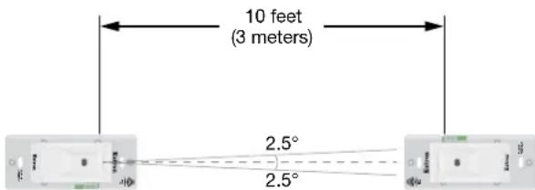
Figure 13. ECM S10 Mounting Requirements
- When all the LEDs light correctly, tighten the screws holding the ECM S10 units to the junction box, taking care not to disturb the alignment between the transmitter and receiver (see figure 12, ①, above).
- Replace the sensor cover (②), if it was removed, and the faceplate (③).
For information on safety guidelines, regulatory compliances, EMI/EMF compatibility, accessibility, and related topics, see the Extron Safety and Regulatory Compliance Guide on the Extron website.
- ECM S10 Partition Sensor • Setup Guide
- Panel Features
- NOTES:
- Front Panel
- To reset the firmware
- Installing the ECM S10 Partition Sensor
- Installation Overview
- Before You Start
- Downloading Software
- ECM S10 Partition Sensor • Setup Guide (Continued)
- Considerations for Placing the ECM S10
- Installation
- Step 1 — Installing the Junction Boxes
- ATTENTION:
- Step 2 — Connecting Cables to the Units
- Partition status signal via eBUS
- Partition status signal via I/O Ports
- Step 3 — Setting the BUS ID Addresses
- eBUS ID Setup
- Setting BUS ID numbers
- Step 4 — Configuring the System
- Step 5 — Testing and Troubleshooting the System
- Ensure that the receiver responds to signals from the transmitter
- Ensure that the ECM \$10 functions in the eBUS system
- Step 6 — Mounting the Transmitter and Receiver
- Step 7 — Aligning the Transmitter and Receiver
Brand : Extron
Model : ECM S10
Category : Detection sensor