
HKTS 14 - Pregnant HARMAN KARDON - Free user manual and instructions
Find the device manual for free HKTS 14 HARMAN KARDON in PDF.


| Product Type | 6-piece home theater speaker system |
| Model Name | HKTS 14 |
| Brand | Harman Kardon |
| System Configuration | 4 satellite speakers, 1 center speaker, 1 powered subwoofer |
| Subwoofer Type | Powered, 12-inch woofer, bass-reflex enclosure |
| Satellite Speaker Type | Two-way, dual 3" midrange drivers, 3/4" dome tweeter |
| Center Speaker Type | Dual-driver, two-way, dual 3" midrange drivers, 3/4" dome tweeter |
| Frequency Response | 25Hz – 20kHz (-6dB) |
| Satellite Power Handling | 10 – 120 Watts per channel |
| Center Power Handling | 10 – 120 Watts per channel |
| Subwoofer Amplifier Power | 200 Watts RMS |
| Impedance (Satellites & Center) | 8 ohms nominal |
| Sensitivity (Satellites & Center) | 86dB @ 1 watt/1 meter |
| Satellite Dimensions (H x W x D) | 9-9/16" x 3-15/16" x 3-5/8" (243mm x 100mm x 92mm) |
| Center Dimensions (H x W x D) | 4" x 9-1/2" x 3-5/8" (102mm x 241mm x 92mm) |
| Subwoofer Dimensions (H x W x D) | 20-1/2" x 14-1/2" x 14-1/2" (521mm x 368mm x 368mm) |
| Satellite Weight | 2.2 lb (1 kg) each |
| Center Weight | 2.2 lb (1 kg) |
| Subwoofer Weight | 48 lb (21.8 kg) |
| Color Coding | CEA standard: White (Front L), Red (Front R), Green (Center), Blue (Surround L), Gray (Surround R), Purple (Subwoofer LFE) |
| Magnetic Shielding | Yes, all speakers magnetically shielded for placement near video monitors |
| Inputs (Subwoofer) | Line-level subwoofer (SUB) input, line-level full-range inputs (L/R), speaker-level inputs, external trigger input |
| Special Features | Auto turn-on (audio-sense and trigger), phase switch, high-cut (low-pass) filter, shelf stands and wall-mount brackets included |
| Included Accessories | 4 shelf stands, 4 wall-mount brackets, 1 x 15' RCA cable (purple), 1 x 15' mini-plug trigger cable, 3 x 20' speaker cables, 2 x 40' speaker cables, color-coded stickers |
Frequently Asked Questions - HKTS 14 HARMAN KARDON
User questions about HKTS 14 HARMAN KARDON
0 question about this device. Answer the ones you know or ask your own.
Ask a new question about this device
Download the instructions for your Pregnant in PDF format for free! Find your manual HKTS 14 - HARMAN KARDON and take your electronic device back in hand. On this page are published all the documents necessary for the use of your device. HKTS 14 by HARMAN KARDON.
USER MANUAL HKTS 14 HARMAN KARDON
Designed to Entertain.
HKTS 14
natural_image
Product photo of a modern stainless steel speaker with cylindrical and meshed components (no visible text or symbols)3 Safety Information
4 Introduction
4 Included
5 SUB-TS14 Subwoofer Amplifier Panel Controls and Connections
7 Speaker Placement
7 Color-Coding System
8 Mounting Options
9 Speaker Connections
9 Speaker-Level Connection Guide
10 Dolby Digital or DTS (or Other Digital Surround Mode) Connection
11 Dolby Pro Logic (Non-Digital) - Line Level
12 Dolby Pro Logic (Non-Digital) — Speaker Level
13 Operation
13 Volume
13 Additional Bass Adjustments
14 Troubleshooting
15 Specifications
Please register your product on our Web site at www.harmankardon.com. Note: You'll need the serial number of your new home theater speaker system. At the same time, you can choose to be notified about our new products and/or special promotions.
Typographical Conventions
In order to help you use this manual, certain conventions have been used.
EXAMPLE – (bold type) indicates a specific control or rear-panel connection on the SUB-TS14 subwoofer
EXAMPLE—(OCR type) indicates a control or switch position on the SUB-TS14 subwoofer
① – (number in a circle) indicates a rear-panel control or connection on the SUB-TS14 subwoofer
2 TABLE OF CONTENTS
Read First! Important Safety Precautions!
CAUTION
RISK OF ELECTRIC SHOCK DO NOT OPEN
CAUTION: To reduce the risk of electric shock, do not remove cover (or back). No user-serviceable parts inside. Refer servicing to qualified service personnel.
CAUTION: To prevent electric shock, do not use this (polarized) plug with an extension cord, receptacle or other outlet unless the blades can be fully inserted to prevent blade exposure.

enclosure that a risk of elect
The lightning flash with arrowhead symbol, within an equilateral triangle, is intended to alert the user to the presence of uninsulated "dangerous voltage" within the product's may be of sufficient magnitude to constitute sic shock to persons.

The exclamation point within an equilateral triangle is intended to alert the user to the presence of important operating and maintenance (servicing) instructions in the accompanying the appliance.
-
Read these instructions.
-
Keep these instructions.
- Heed all warnings.
- Follow all instructions.
- Do not use this apparatus near water.
- Clean only with a dry cloth.
- Do not block any ventilation openings. Install in accordance with the manufacturer's instructions.
- Do not install near any heat sources such as radiators, heat registers, stoves or other apparatus (including amplifiers) that produce heat.
- Do not defeat the safety purpose of the polarized or grounding-type plug. A polarized plug has two blades with one wider than the other. A grounding-type plug has two blades and a third grounding prong. The wide blade or the third prong is provided for your safety. If the provided plug does not fit into your outlet, consult an electrician for replacement of the obsolete outlet.
- Protect the power cord from being walked on or pinched, particularly at plugs, convenience receptacles and the point where they exit from the apparatus.
- Only use attachments/accessories specified by the manufacturer.
-
Use only with the cart, stand, tripod, bracket or table specified by the manufacturer or sold with the apparatus. When a cart is used, use caution when moving the cart/apparatus combination to avoid injury from tip-over.
-
Unplug this apparatus during lightning storms or when unused for long periods of time.
- Refer all servicing to qualified service personnel. Servicing is required when the apparatus has been damaged in any way, such as power-supply cord or plug is damaged, liquid has been spilled or objects have fallen into the apparatus, the apparatus has been exposed to rain or moisture, does not operate normally, or has been dropped.
- Do not use attachments not recommended by the product manufacturer, as they may cause hazards.
- This product should be operated only from the type of power source indicated on the marking label. If you are not sure of the type of power supply to your home, consult your product dealer or local power company. For products intended to operate from battery power, or other sources, refer to the operating instructions.
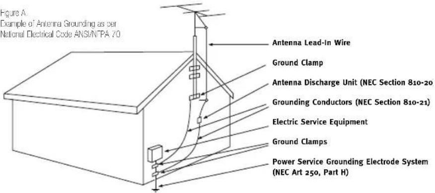
- If an outside antenna or cable system is connected to the product, be sure the antenna or cable system is grounded so as to provide some protection against voltage surges and built-up static charges. Article 810 of the National Electrical Code, ANSI/NFPA 70, provides information with regard to proper grounding of the mast and supporting structure, grounding of the lead-in wire to an antenna discharge unit, size of grounding conductors, location of antenna-discharge unit, connection to grounding electrodes, and requirements for the grounding electrode. See Figure A.
-
An outside antenna system should not be located in the vicinity of overhead power lines or other electric light or power circuits, or where it can fall into such power lines or circuits. When installing an outside antenna system, extreme care should be taken to keep from touching such power lines or circuits, as contact with them might be fatal.
-
Do not overload wall outlets, extension cords, or integral convenience receptacles, as this can result in a risk of fire or electric shock.
- Never push objects of any kind into this product through openings, as they may touch dangerous voltage points or short-out parts that could result in a fire or electric shock. Never spill liquid of any kind on the product.
- The apparatus shall not be exposed to dripping or splashing, and no objects filled with liquids, such as vases, shall be placed on the apparatus.
- Do not attempt to service this product yourself, as opening or removing covers may expose you to dangerous voltage or other hazards. Refer all servicing to qualified service personnel.
- When replacement parts are required, be sure the service technician has used replacement parts specified by the manufacturer or that have the same characteristics as the original part. Unauthorized substitutions may result in fire, electric shock or other hazards.
- Upon completion of any service or repairs to this product, ask the service technician to perform safety checks to determine that the product is in proper operating condition.
- The product should be mounted to a wall or ceiling only as recommended by the manufacturer.
Introduction
Thank you for purchasing the Harman Kardon HKTS 14, with which you're about to begin many years of listening enjoyment. The HKTS 14 has been custom-designed to provide all the excitement and power of the cinema experience in your own living room. To obtain maximum enjoyment from your new home theater speaker system, we urge you to take a few minutes to read through this manual. This will ensure that connections to your receiver or preamp/processor and amplifier or other external devices are made properly. In addition, a few minutes spent learning the functions of the controls will enhance the HKTS 14's performance. If you have any questions about this product, its installation or its operation, please contact your dealer, the best local source of information, or visit our Web site at www.harmankardon.com.
Description and Features
The HKTS 14 is a six-piece home theater speaker system that includes a 12-inch, 200-watt, bass-reflex powered subwoofer; four identical, two-way, dual-midrange satellite speakers for use in the left and right front and rear speaker positions; a voice-matched, dedicated, dual-driver center speaker; shelf stands and wall-mount brackets for the four satellites; and all of the speaker cables you need to connect your speakers to your receiver or preamp/processor and amplifier. The speaker cables and speakers are all color-coded to conform to the CEA standard, simplifying setup, especially when the system is used with a Harman Kardon receiver.
The HKTS 14 subwoofer is easy to connect to your system, since it's equipped with a subwoofer input for use with equipment that has a dedicated subwoofer low frequency output. It also includes stereo speaker-level inputs and outputs for connection to older receivers and processors that do not have a line-level subwoofer output. Other conveniences include a level control, an external trigger input for automatic turn-on when connected to a compatible product, a high-cut (low-pass) filter switch and a phase switch for fine-tuning bass response to suit your listening environment and taste, and audio-sense auto turn-on, which senses the presence of an audio signal and automatically switches the unit from Standby mode to Active mode.
Shelf stands and wall-mount brackets are included for the satellite speakers, and optional HTFS 2 floor stands are available separately from your Harman Kardon dealer.
Harman Kardon invented the high-fidelity receiver more than fifty years ago. With state-of-the-art features and time-honored circuit designs, the HKTS 14 is a perfect complement to a Harman Kardon receiver or any home theater system.
■Complete home theater speaker system
■Identical dual-midrange configuration for satellites and center provides seamless pans
■Speakers are magnetically shielded for placement near video monitors
■Fully color-coded cables and connections simplify setup
■Both line- and speaker-level inputs for use with most audio components
■Subwoofer input offers superior-quality bass reproduction when used with any digital audio system that incorporates bass management or programmable crossovers
■Auto turn-on using trigger input or audio-sense
Included
One center channel speaker
natural_image
Blank gray document or book cover with no visible text, symbols, or markingsOne powered subwoofer

Four satellites for left, right and surrounds, with color-key stickers, mounted on shelf stands
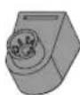
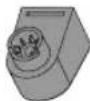
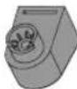
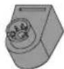
Four wall-mount brackets

One 15' RCA cable for connection to subwoofer (purple)

One 15' mini-plug cable for use with external trigger input (black)
chemical
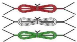
Three molecular structure diagrams showing red, gray, and green ribbon-like arrangements with bondsThree 20' speaker cables for connection to front satellites (red and white) and to center speaker (green)
natural_image
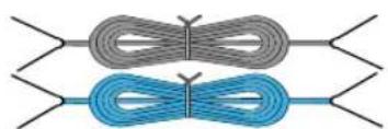
Two coiled cable structures with blue and gray bands, no text or symbols presentTwo 40' speaker cables for connection from receiver to rear satellites (gray and blue)
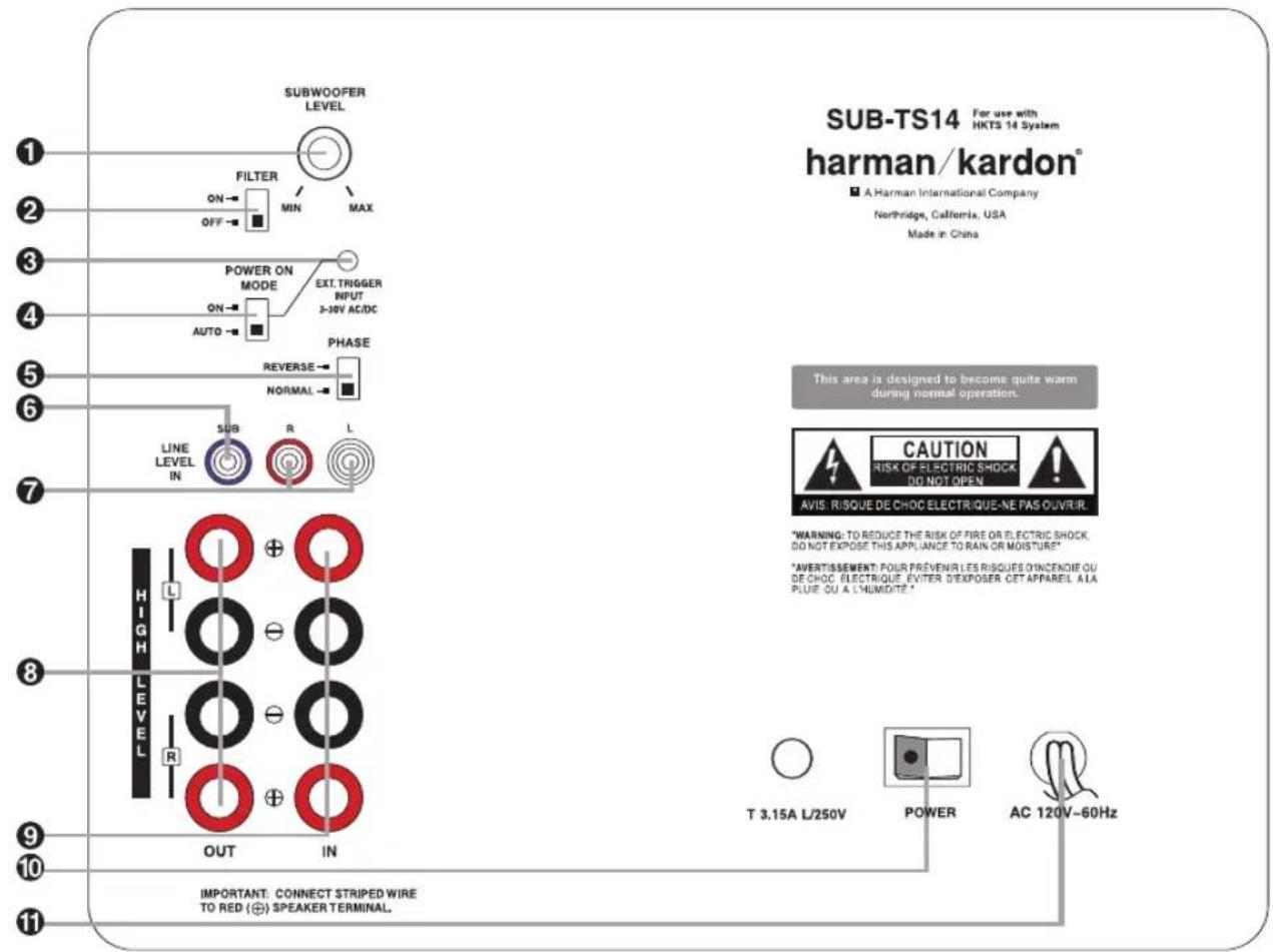
① Subwoofer-Level Control
② High-Cut (Low-Pass) Filter Switch
③ External Trigger Input
4 Audio-Sense On/Off Switch
⑤ Phase Switch
6 Line-Level Subwoofer (SUB) Input
⑦ Line-Level Full-Range Inputs
8 Speaker-Level Outputs
⑨ Speaker-Level Inputs
10 Master Power Switch
11 AC Power Cord
① Subwoofer-Level Control: Volume may be adjusted using the Subwoofer-Level Control. Turn the control clockwise to increase the SUB-TS14's volume, or counterclockwise to decrease it.
② High-Cut (Low-Pass) Filter Switch: Placing this switch in the ON position activates circuitry that cuts out all audio input signals above 120Hz. This allows the SUB-TS14 to focus its power on reproducing the low-frequency portion of the signal, avoiding
inefficiency and distortion. Engage this filter when using the Speaker-Level Inputs ⑨, or when using the Line-Level Full-Range Inputs ⑦, unless your receiver or processor processes its line-level output using a low-pass filter. The filter has no effect when the SUB Input ⑥ is used.
3 External Trigger Input: Use the supplied mini-plug cable to connect the trigger output of another product to this jack. When a trigger signal between 3 and 30 volts (AC
or DC) is detected, the SUB-TS14 amplifier will turn on, even when the Audio-Sense feature has been activated by placing the Audio-Sense On/Off Switch ④ in the AUTO position. The amplifier will remain on for about 10–15 minutes without a trigger signal.
4 Audio-Sense On/Off Switch: When placed in the AUTO position, and when the Master Power Switch 10 is turned on, the SUB-TS14 will automatically turn itself on or
place itself in the Standby mode, depending on whether it is receiving an audio signal. When this switch is placed in the ON position, the SUB-TS14 will remain on, whether or not it is receiving an audio signal.
An LED located on top of the SUB-TS14 indicates whether the SUB-TS14 is in the ON or STANDBY state when used with the Audio-Sense On/Off Switch 4 in the AUTO position. The LED is lit blue to indicate that the SUB-TS14 is receiving an audio signal and is turned on, and the LED is lit amber to indicate that no signal is being received and the SUB-TS14 is in Standby mode.
When the Audio-Sense On/Off Switch 4 is in the ON position, the LED will be lit blue, whether or not an audio signal is present.
When the Master Power Switch ⑩ is turned off, the LED goes dark, no matter which position the Audio-Sense On/Off Switch ④ is in.
⑤ Phase Switch: This switch determines whether the SUB-TS14 subwoofer's piston-like action moves in and out in phase with the main speakers. If the speakers were to play out of phase, the sound waves produced by the subwoofer would be cancelled out, reducing bass response. This phenomenon depends in part on the relative placement of the speakers in the room. In most cases, the Phase Switch ⑤ should be left in the NORMAL position. However, it does no harm to experiment with the Phase Switch 5, and you may leave it in the position that maximizes bass response.
6 Line-Level Subwoofer (SUB) Input: Connect the subwoofer output of a receiver with digital surround sound decoding, such as Dolby® Digital or DTS®, to this input. This input bypasses the SUB-TS14's internal crossover circuitry, and should only be used with a filtered signal. If your receiver does not have digital decoding, you should use the Line-Level Full-Range Inputs 7 instead.
7 Line-Level Full-Range Inputs: Connect the line-level subwoofer output or preamp output(s) of your receiver or amplifier to these inputs. If your receiver does not have a separate subwoofer output, use a Y-adapter (not supplied) to bridge the receiver's preamp output to the main amp input for that channel, and connect the long end of the adapter to the corresponding line-level input on the SUB-TS14. If your receiver has only a single subwoofer output, you may connect it to either the left or right line-level input on the SUB-TS14, and no Y-adapter is needed.
⑧ Speaker-Level Outputs: If you are using the Speaker-Level Inputs ⑨ on the SUB-TS14, you should connect these binding post terminals to your front left and right speakers, remembering to maintain polarity by connecting the (+) terminal on the SUB-TS14 subwoofer to the (+) terminal on the speaker, and the (−) terminal on the SUB-TS14 subwoofer to the (−) terminal on the speaker. If you are not using the Speaker-Level Inputs ⑨, then connect your front left and right speakers directly to your receiver or amplifier. See pages 9 through 12 for further information on speaker connections.
⑨ Speaker-Level Inputs: If your receiver or amplifier does not have a line-level subwoofer output, connect these binding-post terminals to the main left and right speaker terminals of your receiver or amplifier. Remember to maintain polarity by connecting the (+) terminal on the receiver/amplifier to the (+) terminal on the SUB-TS14 subwoofer, and the (−) terminal on the receiver/amplifier to the (−) terminal on the SUB-TS14 subwoofer.
10 Master Power Switch: Place this switch in the "●" position to power-on the SUB-TS14 subwoofer. The SUB-TS14 will then be either in the Standby mode or completely on, depending on the position of the
Audio-Sense On/Off Switch 4
1 AC Power Cord: Make sure to plug this cord into an active, unswitched electrical outlet for proper operation of the SUB-TS14. The cord should not be plugged into the accessory outlets found on some audio components.
Color-Coding System
The HKTS 14 uses the channel color-coding system established by the Consumer Electronics Association to make setting up your home theater speaker system as easy as possible. Your system includes a set of colored stickers that may be placed near the speaker terminals of each of the four satellite speakers according to the key below. It doesn't matter which satellite speaker is used for any of the front or rear positions. (The center speaker and powered subwoofer are already color-coded for you.)
| Speaker Sticker (or Terminal) Position and Cable Color | |
| Front Left White | |
| Front Right Red | |
| Center Green | |
| Surround Left Blue | |
| Surround Right Gray | |
| Subwoofer (LFE) Purple | |
Before you begin to connect cables, it is important to set up your speakers in their correct locations in the room.
Optimally, the speakers should be placed in a circle with the listening position at its center. The distance from the listening position to the video display forms the radius of the circle.
The speakers should be angled so that they directly face the listening position. The center speaker is placed either on top of or below the video display screen.
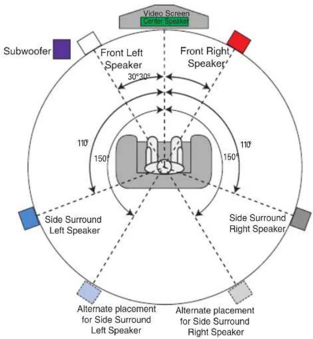
The front left and right speakers are placed along the circle, about 30 degrees from the center speaker and angled toward the listener.
It is best to place the front left/right and center speakers as close to the same height as possible, preferably about the same height as the listener's ears. In any event, the center speaker should be no more than two feet above or below the left/right speakers.
The side surround speakers should be placed 110 degrees from the center speaker; that is, slightly behind and angled toward the listener. If this isn't feasible, place the surround speakers behind the listener, with each surround speaker facing the opposite-side front speaker. The surround speakers may be placed a little higher than the listener's ears.
The subwoofer's location is less critical, since low-frequency sounds are omni-directional. Placing the subwoofer close to a wall or in a corner will reinforce the low frequencies, and may create a "boomy" sound. You may wish to experiment over time by placing the subwoofer where the listener normally sits and then walking around the room until the low frequencies sound best. Place the subwoofer in that spot.
Satellites and Surrounds
natural_image
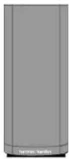
Exterior view of a modern office building (no signage)The satellite speakers may be placed on a shelf.
natural_image
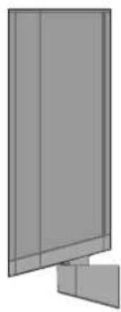
Pure diagram of a cabinet or shelf structure without any text, numbers, or symbolsThey may be wall-mounted using the supplied brackets.
Wall-Mounting
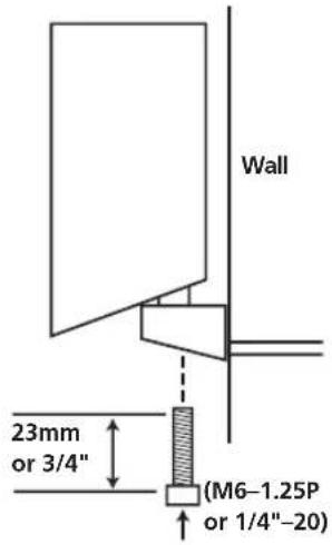
Unscrew the bolt that attaches the black shelf stand to the bottom of the speaker. Store the stand and bolt in a safe place in case they are needed for a future installation.
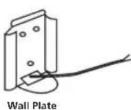
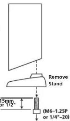
Mount the wall-bracket attachment plate on the wall in the desired location. If possible, position the
speakers so that the mounting screws (not included; use size #8) may be installed directly into a wooden wall stud. If that is not possible, use optional wall anchors that are rated to support at least twenty-five pounds. The customer is responsible for proper selection and use of mounting hardware, available through hardware stores, to properly and safely wall-mount the speakers.
Referring to the speaker connection instructions on pages 9 through 12, thread the appropriate speaker cable through the opening in the bottom of the wall plate, and then through the back of the bracket as shown in the diagram. The bracket has two openings
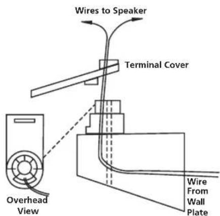
on top: a round screw hole, and an arc-shaped opening in front of it. The speaker cable should be threaded through the arc-shaped opening, not the screw hole.
Attach the bracket to the wall plate by inserting the tab at the top of the wall plate into the slot on top of the bracket and snapping the bracket onto the wall plate.
Thread the cable through the round opening in the terminal cover, and then insert the speaker wires into the terminals on the underside of the speaker, remembering to observe the correct polarity (see page 9).
Place the terminal cover over the opening on the underside of the speaker so that it fits flush against the speaker and covers the terminals, with its round opening exposing the threaded insert. The bracket fits through the round opening in the terminal cover.
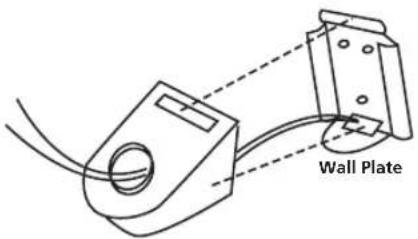
Insert the supplied bracket bolt up through the bottom of the bracket and terminal cover, and screw it into the threaded insert on the underside of the speaker. The bolt should be snug, but not so tight as to prevent the bracket from pivoting.
The wall-mounted speaker may be pivoted from side to side; however, the bracket is not designed to tilt up or down, and attempting to tilt it will damage the bracket and possibly the wall, which would not be covered by your warranty.
Speaker-Level Connection Guide
IMPORTANT NOTE: Before making speaker connections, be certain that your receiver or audio power amplifier is turned off and preferably unplugged from its AC power source. The SUB-TS14 subwoofer should not be connected to an AC power source until all speaker wire connections have been made.
Speakers and electronics terminals have corresponding (+) and (−) terminals. Most manufacturers of speakers and electronics, including Harman Kardon, use red to denote the (+) terminal and black for the (−) terminal.
natural_image
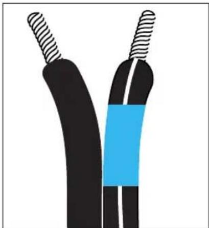
Diagram of two black and blue electrical wires with striped ends, no text or symbols presentNewer Harman Kardon receivers conform to the new CEA standard and therefore use a color other than red or black for the (+) terminal to indicate some speaker positions: e.g., surround left. Although the HKTS 14 system has red and black collars on the individual speaker terminals to denote the positive and negative connections, your system includes a colored band on the positive lead at both ends of every speaker cable and a matching colored sticker for each of the four satellite speakers, conforming to the key on page 7. The center speaker has a green (+) terminal, and the subwoofer has a purple SUB input jack. This system is intended to help you ensure that the speaker in each location is connected to the correct terminals on your receiver or amplifier.
The (+) lead of the speaker wire is indicated with a stripe and has the colored band corresponding to the speaker's position. It is important to connect all speakers identically: (+) on the speaker to (+) on the amplifier and (−) on the speaker to (−) on the amplifier. Wiring "out of phase" results in thin sound, weak bass and a poor stereo image.
With the advent of multichannel surround sound systems, connecting all of the speakers in your system with the correct polarity remains equally important in order to preserve the proper ambience and directionality of the program material.
To connect the supplied speaker wires to the satellite and center speaker terminals located on the bottom of each speaker, press the red or black tab, insert the bare end of the wire into the hole and release the tab. Gently tug on the wire to make sure that it is fully inserted.
For the best performance, Harman Kardon recommends that the subwoofer be connected using either the Line-Level Subwoofer (SUB) Input ⑥ or the Line-Level Full-Range Inputs ⑦. However, if the application requires the use of the speaker-level connections for the subwoofer, unscrew the binding-post collar until the pass-through hole in the center post is visible under the collar. Insert the bare end of the wire through this hole; then screw the collar down until the connection is light. The hole in the center of each collar is intended for use with banana-type connectors.

natural_image
Three identical diagrams showing red cylindrical objects with black circular elements, connected by arrows (no text or symbols)Dolby® Digital or DTS® (or Other Digital Surround Mode) Connection
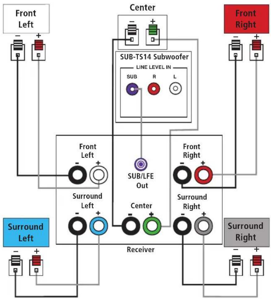
USE THIS INSTALLATION METHOD FOR DOLBY DIGITAL, DTS OR OTHER DIGITAL SURROUND PROCESSORS:
Use the line-level input jack marked SUB
⑥ for the Low-Frequency Effects channel. Connect this jack to the subwoofer output or LFE output on your receiver or amplifier. Connect each speaker to the corresponding speaker terminals on your receiver or amplifier.
Make sure you've configured your surround sound processor for "Subwoofer On." The front left, front right, center and surround speakers should all be set to "Small."
When all connections have been made, plug the AC power cord on the subwoofer into an AC outlet.
flowchart
graph TD
    A["Front Left"] --> B["+"]
    C["Center"] --> D["+"]
    E["Sub-TS14 Subwoofer LINE LEVEL IN"] --> F["SUB"]
    G["Front Right"] --> H["+"]
    I["Front Left"] --> J["+"]
    K["Surround Left"] --> L["+"]
    M["Surround Right"] --> N["+"]
    O["Sub/LFE Out"] --> P["+"]
    Q["Center"] --> R["+"]
    S["Receiver"] --> T["+"]
    U["Front Right"] --> V["+"]
    W["Surround Right"] --> X["+"]
Dolby Pro Logic®
(Non-Digital) - Line Level
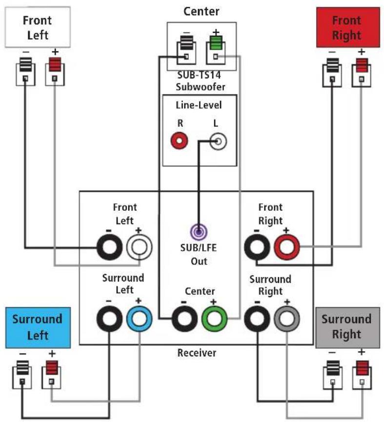
USE THIS INSTALLATION METHOD FOR DOLBY PRO LOGIC APPLICATIONS (NOT DOLBY DIGITAL, DTS OR OTHER DIGITAL PROCESSING), WHERE THE RECEIVER/PROCESSOR IS EQUIPPED WITH A SUBWOOFER OUTPUT, OR A VOLUME-CONTROLLED PREAMP (LINE-) LEVEL OUTPUT:
Use the supplied RCA-type interconnect cable to connect the line-level subwoofer output on your receiver or amplifier to either the left or right Line-Level Full-Range
Input 7 on the SUB-TS14 subwoofer. Use both the left and right inputs on the subwoofer if your receiver or processor has both left and right line-level outputs. In that case, you will need to supply a second interconnect cable.
If your receiver is equipped with line-level outputs but does not have a separate subwoofer output, use a Y-adapter (not supplied) to bridge the receiver's preamp output to the main amp input for that channel, and connect the long end of the adaptor to the corresponding line-level input on the SUB-TS14.
IMPORTANT: Do not use the SUB Input ⑥ on the subwoofer with Dolby Pro Logic processors.
If your receiver/processor has a built-in low-pass crossover filter for the subwoofer output, you may use the SUB Input ⑥ to bypass the subwoofer's internal crossover.
Connect each speaker to the corresponding speaker terminals on your receiver or amplifier.
Make sure that you have configured your surround sound processor for "Subwoofer On." The front left, front right, center and surround speakers should all be set to "Small."
When all connections have been made, plug the AC power cord on the subwoofer into an AC outlet.
flowchart
graph TD
    A["Front Left"] --> B["+"]
    B --> C["Center"]
    C --> D["SUB-TS14 Subwoofer"]
    D --> E["Line-Level R L"]
    E --> F["Sub/LFE Out"]
    F --> G["Receiver"]
    G --> H["Front Right"]
    H --> I["+"]
    I --> J["Surround Right"]
    J --> K["+"]
    K --> L["Surround Left"]
    L --> M["+"]
    M --> N["Front Left"]
    style A fill:#f9f,stroke:#333
    style C fill:#ccf,stroke:#333
    style F fill:#cfc,stroke:#333
    style H fill:#fcc,stroke:#333
    style J fill:#cff,stroke:#333
    style K fill:#ffc,stroke:#333
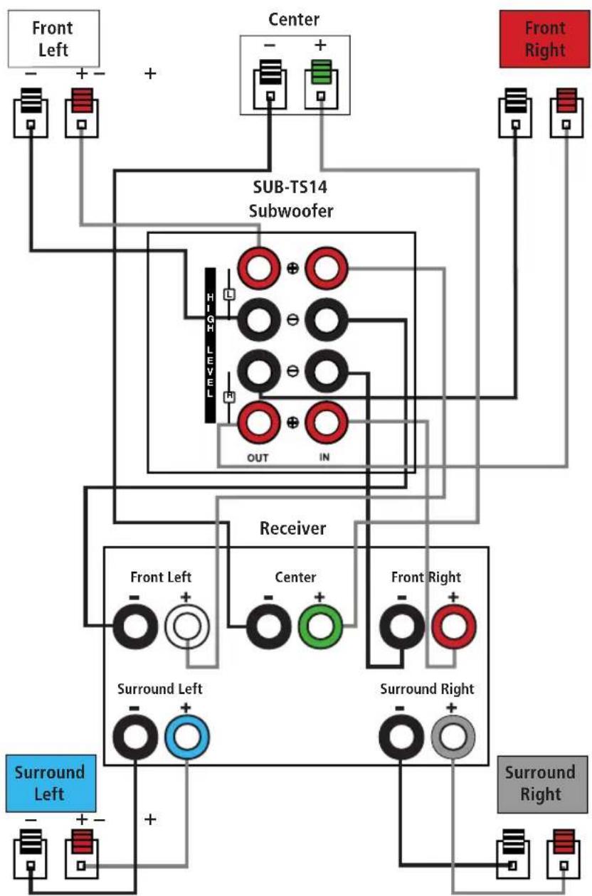
Dolby Pro Logic (Non-Digital) – Speaker Level
USE THIS INSTALLATION METHOD FOR DOLBY PRO LOGIC APPLICATIONS (NOT DOLBY DIGITAL, DTS OR OTHER DIGITAL PROCESSING), WHERE THE RECEIVER/PROCESSOR DOES NOT HAVE A SUB-WOOFER OUTPUT, OR A VOLUME-CONTROLLED PREAMP (LINE-) LEVEL OUTPUT:
Connect your receiver or amplifier's front left and right speaker terminals to the left and right Speaker-Level Input ⑨ terminals on the SUB-TS14 subwoofer that are marked "High Level In." Connect the left and right Speaker-Level Output ⑧ terminals on the SUB-TS14 subwoofer that are marked "High Level Out" to the corresponding terminals on the back of your front left and right speakers.
Connect your receiver or amplifier's center, and surround left and right speaker terminals to the corresponding terminals on the back of your center, and surround left and right speakers.
When all connections have been made, plug the AC power cord on the subwoofer into an AC outlet.
flowchart
graph TD
    A["Front Left"] --> B["+"]
    C["Center"] --> D["+"]
    E["Sub-TS14 Subwoofer"] --> F["High Level"]
    F --> G["OUT"]
    F --> H["IN"]
    I["Front Right"] --> J["+"]
    K["Receiver"] --> L["Front Left"]
    K --> M["Center"]
    K --> N["Front Right"]
    O["Surround Left"] --> P["+"]
    Q["Surround Right"] --> R["+"]
    S["+"] --> T["Ground"]
    U["+"] --> V["Ground"]
Move the Master Power Switch 10 (marked Power) to the “•” (On) position. The SUB-TS14 subwoofer will automatically turn itself on or go into Standby mode, depending on whether or not a signal is being sent to it by your receiver or surround processor, and provided that the Audio-Sense On/Off Switch 4 is moved down so that it is in the AUTO position.
When your receiver or amplifier is off, or is not sending program material to the subwoofer, the subwoofer will be in Standby mode and the LED Indicator on the top of the subwoofer will turn amber. When the subwoofer senses an audio signal, it will automatically turn itself on and the LED Indicator will turn blue. If the subwoofer does not sense a signal after approximately twenty minutes, it will automatically go into Standby mode.
When the Audio-Sense On/Off Switch 4 is switched to the ON position, the subwoofer will remain on, whether or not program material is playing, and the LED Indicator will remain lit blue.
If your receiver, processor or amplifier is equipped with a compatible trigger output, you may connect it to the SUB-TS14's
External Trigger Input ③. When you turn on your component, if you have set it up correctly, it will send an electrical trigger signal to the SUB-TS14, which will cause the subwoofer to turn itself on, even when the
Audio-Sense On/Off Switch 4 has been placed in the AUTO position and no audio signal is detected.
The trigger signal must be between 3 and 30 volts, although it may be an AC or DC signal, and an AC signal may be 50Hz or 60Hz.
If you'll be away from home for an extended period of time, or if the subwoofer will not be used, switch the Master Power Switch 10 to the OFF position.
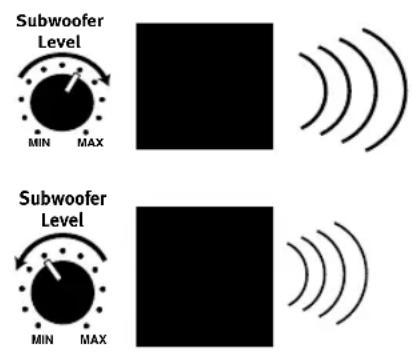
Volume
Volume can be adjusted using the Subwoofer-Level Control ①, as shown. Turn the control knob clockwise to increase the volume of the subwoofer, and counterclockwise to decrease the subwoofer's volume.
Additional Bass Adjustments
In addition to the volume adjustments described above, the SUB-TS14 subwoofer includes a Phase Switch ⑤ and a Filter Switch ② that can be used to adjust the bass response to suit your listening environment or taste.
In most situations, the Phase Switch 5 should be left in the NORMAL position. If you suspect that the subwoofer is playing out of phase with the other speakers, which would tend to diminish bass response, try placing this switch in the REVERSE position. There is no harm in experimenting, and you may return the switch to the NORMAL position at any time. If you rearrange your room and reposition the speakers, it would be a good idea to check whether they are in phase by flipping this switch.
The High-Cut (Low-Pass) Filter Switch
2 limits the frequencies of the audio signal inputted to the subwoofer to the low frequencies that the subwoofer reproduces best. This allows the subwoofer to perform more efficiently, and with superior bass reproduction, minimizing distortion that might occur if the subwoofer attempted to reproduce higher frequencies. This switch should be left in the ON position, except:
- When the SUB Input ⑥ is being used, in which case it has no effect, or
- When the Speaker-Level Inputs ⑨ or the Line-Level Full-Range Inputs ⑦ are being used with a crossover or filter aboard the receiver or processor.
In these two circumstances, place the switch in the OFF position.
SYMPTOM SOLUTION
| If there is no sound fromany of the speakers: | Check that receiver/amplifier is on and a source is playing.Check that the powered subwoofer is plugged in and its Master Power Switch 10 is switched on to the “•” position.Check all wires and connections between receiver/amplifier and speakers. Make sure all wires are connected.Make sure none of the speaker wires are frayed, cut, punctured or touching other wires.Review proper operation of your receiver/amplifier. |
| If there is no sound comingfrom one speaker: | Check the “Balance” control on your receiver/amplifier.Check all wires and connections between receiver/amplifier and speakers. Make sure all wires are connected.Make sure none of the speaker wires are frayed, cut or punctured, and that no wires are touching each other.In Dolby Digital or DTS mode, make sure that the receiver/processor is configured so that the speaker in question is enabled.Tum off all electronics and switch the speaker in question with one of the other speakers that is working correctly. Turn everything back on, and determine whether the problem is in the same place: i.e., the speaker that was working previously now has no sound and the speaker that was not working now sounds fine; or whether it has moved: i.e., the speaker that was not working still has no sound and the speaker that was working is still fine. If the problem is in the same place, the source of the problem is most likely with your receiver or amplifier, and you should consult the owner’s manual for that product for further information. If the problem has followed the speaker, consult your dealer for further assistance or, if that is not possible, visit our Web site at www.harmankardon.com for further information. |
| If there is no sound fromthe center speaker: | Check all wires and connections between receiver/amplifier and speaker. Make sure all wires are connected.Make sure none of the speaker wires are frayed, cut, punctured or touching other wires.If your receiver/processor is set in Dolby Pro Logic mode, make sure the center speaker is not in phantom mode.If your receiver/processor is set in Dolby Digital or DTS mode, make sure the receiver/processor is configured so that the center speaker is enabled. |
| If the system plays at low volumes but shuts off as volume is increased: | Check all wires and connections between receiver/amplifier and speakers. Make sure all wires are connected.Make sure none of the speaker wires are frayed, cut, punctured or touching other wires.If more than one pair of main speakers is being used, check the minimum impedance requirements of your receiver/amplifier. |
| If there is low (or no) bass output: | Make sure the SUB 6 or Line-Level Inputs 7 of the SUB-TS14 subwoofer and SUB or LFE output of your receiver or amplifier are properly connected by the RCA-type interconnect cable.If you are using the SUB-TS14’s Speaker-Level Inputs 9, check your speaker cables to make sure they are all connected; that none of the wires are frayed, cut, punctured or touching other wires; and that you have maintained the correct polarity by connecting positive terminals to positive terminals, and negative terminals to negative terminals.Make sure the subwoofer is plugged into an active electrical outlet and its Master Power Switch 10 is switched on to the “•” position.Check the speaker setup (bass management) settings in your A/V receiver or processor to make certain that the front, center and surround speakers are configured for “Small,” and that the subwoofer is set for “Yes” or “On.” |
| If there is no sound fromthe surround speakers: | Check all wires and connections between receiver/amplifier and speakers. Make sure all wires are connected. Make sure none of the speaker wires are frayed, cut, punctured or touching other wires.Review proper operation of your receiver/processor and its surround sound features.Make sure the movie or TV show you are watching is recorded in a surround sound mode. If it is not, check to see whether your receiver/processor has other surround modes you may use.In Dolby Digital or DTS mode, make sure your receiver/processor is configured so that the surround speakers are enabled.Review the operation of your DVD player and the jacket of your DVD to make sure that the DVD features the desired Dolby Digital or DTS mode, and that you have properly selected that mode using both the DVD player’s menu and the DVD disc’s menu. |
HKTS 14 System
Frequency Response:
25Hz - 20kHz (-6dB)
SAT-TS14
Satellites
Recommended Power:
10 – 120 Watts
Impedance:
8 Ohms nominal
Sensitivity:
86dB @ 1 watt/1 meter
Tweeter:
One 3/4" dome, video-shielded
Midrange:
Dual 3" drivers, video-shielded
Dimensions (H x W x D):
9-9/16" x 3-15/16" x 3-5/8"
243mm x 100mm x 92mm
Weight:
2.2 lb/1kg
CEN-TS14
Center
Recommended Power:
10 - 120 Watts
Impedance:
8 Ohms nominal
Sensitivity:
86dB @ 1 watt/1 meter
Tweeter:
One 3/4" dome, video-shielded
Midrange:
Dual 3" drivers, video-shielded
Dimensions (H x W x D):
4" x 9-1/2" x 3-5/8"
102mm x 241mm x 92mm
Weight:
2.2 lb/1kg
SUB-TS14
Subwoofer
Amplifier:
200 Watts RMS
Bass:
12" Woofer, bass-reflex enclosure
External Trigger Input Voltage:
3\~30 Volts AC/DC
Dimensions (H x W x D):
20-1/2" x 14-1/2" x 14-1/2"
521mm x 368mm x 368mm
Weight:
48 lb/21.8kg
All features and specifications are subject to change without notice.
Harman Kardon is a trademark of Harman International Industries, Incorporated, registered in the United States and/or other countries.
Designed to Entertain is a trademark of Harman International Industries, Incorporated.
Dolby and Pro Logic are registered trademarks of Dolby Laboratories.
DTS is a registered trademark of DTS, Inc.
harman/kardon®
H A Harman International Company
250 Crossways Park Drive, Woodbury, New York 11797
516.255.HKHK (4545) Fax: 516.682.3523
© 2006 Haman International Industries, Incorporated.
All rights reserved.
Printed 9/06 Part No. 406-000-05559-E
- HKTS 14
- Typographical Conventions
- TABLE OF CONTENTS
- Read First! Important Safety Precautions!
- CAUTION
- RISK OF ELECTRIC SHOCK DO NOT OPEN
- Introduction
- Description and Features
- Included
- Audio-Sense On/Off Switch 4
- Color-Coding System
- Satellites and Surrounds
- Wall-Mounting
- Speaker-Level Connection Guide
- Dolby® Digital or DTS® (or Other Digital Surround Mode) Connection
- Dolby Pro Logic®
- (Non-Digital) - Line Level
- Dolby Pro Logic (Non-Digital) – Speaker Level
- Volume
- Additional Bass Adjustments
- The High-Cut (Low-Pass) Filter Switch
- HKTS 14 System
- SAT-TS14
- Satellites
- CEN-TS14
- Center
- SUB-TS14
- Subwoofer
Brand : HARMAN KARDON
Model : HKTS 14
Category : Pregnant