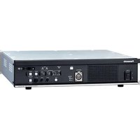
AK-HCU250PSJ - Unité de contrôle caméra PANASONIC - Free user manual and instructions
Find the device manual for free AK-HCU250PSJ PANASONIC in PDF.


| Type of Product | Camera Control Unit (CCU) |
| Brand | Panasonic |
| Model | AK-HCU250PSJ |
| Dimensions (W x H x D) | 430 x 44 x 350 mm |
| Weight | 5.5 kg |
| Power Supply | AC 100-240 V, 50/60 Hz |
| Power Consumption | 150 W |
| Operating Temperature | 0°C to 40°C |
| Operating Humidity | 20% to 80% (non-condensing) |
| Video Inputs | 2x 3G-SDI, 1x HDMI |
| Video Outputs | 2x 3G-SDI, 1x HDMI loop-through |
| Control Interfaces | Ethernet (RJ-45), RS-232C, GPI |
| Intercom | Built-in intercom (headset not included) |
| Main Functions | Camera control, video processing, power to camera head, tally indication |
| Mounting | 19-inch rack-mountable (1U) |
| Cooling | Fan cooling, ensure proper ventilation |
| Maintenance | Clean exterior with dry cloth; avoid liquids |
| Safety | Use only with grounded outlet; do not remove cover; risk of electric shock |
| Spare Parts | Available through Panasonic authorized service centers |
| Repairability | Repairs only by qualified technicians |
| Warranty | 2 years (check local regulations) |
Frequently Asked Questions - AK-HCU250PSJ PANASONIC
User questions about AK-HCU250PSJ PANASONIC
0 question about this device. Answer the ones you know or ask your own.
Ask a new question about this device
Download the instructions for your Unité de contrôle caméra in PDF format for free! Find your manual AK-HCU250PSJ - PANASONIC and take your electronic device back in hand. On this page are published all the documents necessary for the use of your device. AK-HCU250PSJ by PANASONIC.
USER MANUAL AK-HCU250PSJ PANASONIC
Operating Instructions
Camera Control Unit
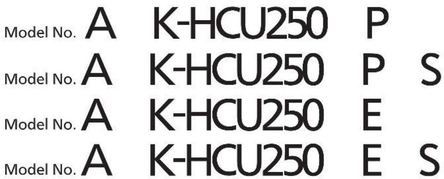


Please carefully read this manual, and save this manual for future use. Before using this product, be sure to read "Read this first!" (pages 2 to 6).
Read this first!
WARNING:
This equipment must be grounded.
To ensure safe operation, the three-pin plug must be inserted only into a standard three-pin power outlet which is effectively grounded through normal household wiring.
Extension cords used with the equipment must have three cores and be correctly wired to provide connection to the ground. Wrongly wired extension cords are a major cause of fatalities.
The fact that the equipment operates satisfactorily does not imply that the power outlet is grounded or that the installation is completely safe. For your safety, if you are in any doubt about the effective grounding of the power outlet, please consult a qualified electrician.
WARNING:
- To reduce the risk of fire or electric shock, do not expose this equipment to rain or moisture.
- To reduce the risk of fire or electric shock, keep this equipment away from all liquids. Use and store only in locations which are not exposed to the risk of dripping or splashing liquids, and do not place any liquid containers on top of the equipment.
WARNING:
Always keep memory cards (optional accessory) out of the reach of babies and small children.
WARNING:
Installation should only be performed by qualified installation personnel. Improper installation may result in the entire apparatus falling down and causing injury.
WARNING:
This equipment is compliant with Class A of CISPR 32. In a residential environment this equipment may cause radio interference.
CAUTION:
Do not remove panel covers by unscrewing.
To reduce the risk of electric shock, do not remove the covers. No user serviceable parts inside.
Refer servicing to qualified service personnel.
CAUTION:
To reduce the risk of fire or electric shock and annoying interference, use the recommended accessories only.
CAUTION:
In order to maintain adequate ventilation, do not install or place this unit in a bookcase, built-in cabinet or any other confined space. To prevent risk of electric shock or fire hazard due to overheating, ensure that curtains and any other materials do not obstruct the ventilation.
CAUTION:
The mains plug of the power supply cord shall remain readily operable.
The AC receptacle (mains socket outlet) shall be installed near the equipment and shall be easily accessible. To completely disconnect this equipment from the AC mains, disconnect the power cord plug from the AC receptacle.
CAUTION:
Invisible Laser radiation is emitted from the Optical fiber connector when this product is turned on. Don't look into directly into the Optical fiber connector of this product.
CAUTION:
This product uses a semiconductor laser system and is a Class 1 Laser Product complies with Radiation Performance Standards, 21CFR SUBCHAPTER J. Use of controls or adjustments or performance of procedures other than those specified herein may result in hazardous radiation exposure. Don't make any modifications. Don't repair by yourself. Refer servicing to qualified personnel.
CAUTION:
- Keep the temperature inside the rack to between 0 °C to 40 °C (32 °F to 104 °F).
- Bolt the rack securely to the floor so that it will not topple over when the unit is drawn out.
CAUTION:
Naked flame sources, such as lighted candles, should not be placed on the apparatus.
CAUTION:
To reduce the risk of fire or electric shock, refer mounting of the optional interface boards to qualified service personnel.
For U.S.A. and Canada
CAUTION:
This apparatus can be operated at a voltage in the range of 100–240 V AC.
Voltages other than 120 V are not intended for U.S.A. and Canada.
Operation at a voltage other than 120 V AC may require the use of a different AC plug. Please contact either a local or foreign Panasonic authorized service center for assistance in selecting an alternate AC plug.
NOTIFICATION (Canada)
CAN ICES-003 (A)/NMB-003(A)

indicates safety information.
For AK-HCU250P, AK-HCU250PS
IMPORTANT SAFETY INSTRUCTIONS
1) Read these instructions.
2) Keep these instructions.
3) Heed all warnings.
4) Follow all instructions.
5) Do not use this apparatus near water.
6) Clean only with dry cloth.
7) Do not block any ventilation openings. Install in accordance with the manufacturer's instructions.
8) Do not install near any heat sources such as radiators, heat registers, stoves, or other apparatus (including amplifiers) that produce heat.
9) Do not defeat the safety purpose of the polarized or grounding-type plug. A polarized plug has two blades with one wider than the other. A grounding-type plug has two blades and a third grounding prong. The wide blade or the third prong are provided for your safety. If the provided plug does not fit into your outlet, consult an electrician for replacement of the obsolete outlet.
10) Protect the power cord from being walked on or pinched particularly at plugs, convenience receptacles, and the point where they exit from the apparatus.
11) Only use attachments/accessories specified by the manufacturer.
12) Use only with the cart, stand, tripod, bracket, or table specified by the manufacturer, or sold with the apparatus. When a cart is used, use caution when moving the cart/apparatus combination to avoid injury from tip-over.

13) Unplug this apparatus during lightning storms or when unused for long periods of time.
14) Refer all servicing to qualified service personnel. Servicing is required when the apparatus has been damaged in any way, such as power-supply cord or plug is damaged, liquid has been spilled or objects have fallen into the apparatus, the apparatus has been exposed to rain or moisture, does not operate normally, or has been dropped.
FCC NOTICE (USA)
Supplier's Declaration of Conformity
Model Number: AK-HCU250P/AK-HCU250PS
Trade Name: Panasonic
Responsible Party: Panasonic Corporation of North America
Two Riverfront Plaza, Newark, NJ 07102
Support contact: 1-800-524-1448
This device complies with part 15 of the FCC Rules.
Operation is subject to the following two conditions:
(1) This device may not cause harmful interference, and (2) this device must accept any interference received, including interference that may cause undesired operation.
FCC Note:
This equipment has been tested and found to comply with the limits for a class A digital device, pursuant to Part 15 of the FCC Rules. These limits are designed to provide reasonable protection against harmful interference when the equipment is operated in a commercial environment. This equipment generates, uses, and can radiate radio frequency energy, and if not installed and used in accordance with the instruction manual, may cause harmful interference to radio communications. Operation of this equipment in a residential area is likely to cause harmful interference in which case the user will be required to correct the interference at his own expense.
Warning:
To assure continued FCC emission limit compliance, the user must use only shielded interface cables when connecting to external units. Also, any unauthorized changes or modifications to this equipment could void the user's authority to operate it.

indicates safety information.
For AK-HCU250E, AK-HCU250ES
Caution for AC Mains Lead
FOR YOUR SAFETY PLEASE READ THE FOLLOWING TEXT CAREFULLY.
This product is equipped with 2 types of AC mains cable. One is for continental Europe, etc. and the other one is only for U.K.
Appropriate mains cable must be used in each local area, since the other type of mains cable is not suitable.
FOR CONTINENTAL EUROPE, ETC.
Not to be used in the U.K.

FOR U.K. ONLY
If the plug supplied is not suitable for your socket outlet, it should be cut off and appropriate one fitted.

FOR U.K. ONLY
This appliance is supplied with a moulded three pin mains plug for your safety and convenience.
A 13 amp fuse is fitted in this plug.
Should the fuse need to be replaced please ensure that the replacement fuse has a rating of 13 amps and that it is approved by ASTA or BSI to BS1362.
Check for the ASTA mark or the BSI mark on the body of the fuse.
If the plug contains a removable fuse cover you must ensure that it is refitted when the fuse is replaced.
If you lose the fuse cover the plug must not be used until a replacement cover is obtained.
A replacement fuse cover can be purchased from your local Panasonic Dealer.
How to replace the fuse
- Open the fuse compartment with a screwdriver.

- Replace the fuse.


indicates safety information.
EMC NOTICE FOR THE PURCHASER/USER OF THE APPARATUS
1. Pre-requisite conditions to achieving compliance with the above standards
<1> Peripheral equipment to be connected to the apparatus and special connecting cables
- The purchaser/user is urged to use only equipment which has been recommended by us as peripheral equipment to be connected to the apparatus.
- The purchaser/user is urged to use only the connecting cables described below.
<2> For the connecting cables, use shielded cables which suit the intended purpose of the apparatus.
• Video signal connecting cables
Use double-shielded coaxial cables, which are designed for 75-ohm type high-frequency applications, for SDI (Serial Digital Interface).
Coaxial cables, which are designed for 75-ohm type high-frequency applications, are recommended for analog video signals.
• Audio signal connecting cables
If your apparatus supports AES/EBU serial digital audio signals, use cables designed for AES/EBU.
Use shielded cables, which provide quality performance for high-frequency transmission applications, for analog audio signals.
- Other connecting cables (LAN, RS-422)
Use double shielded cables, which provide quality performance for high-frequency applications, as connecting cables.
- When connecting to the DVI signal terminal, use a cable with a ferrite core.
- If your apparatus is supplied with ferrite core(s), they must be attached on cable(s) following instructions in this manual.
2. Performancelevel
The performance level of the apparatus is equivalent to or better than the performance level required by these standards.
However, the apparatus may be adversely affected by interference if it is being used in an EMC environment, such as an area where strong electromagnetic fields are generated (by the presence of signal transmission towers, cellular phones, etc.). In order to minimize the adverse effects of the interference on the apparatus in cases like this, it is recommended that the following steps be taken with the apparatus being affected and with its operating environment:
- Place the apparatus at a distance from the source of the interference.
- Change the direction of the apparatus.
- Change the connection method used for the apparatus.
- Connect the apparatus to another power outlet where the power is not shared by any other appliances.
AEEE Complies with Directive of Turkey.
Manufactured by:
Panasonic Connect Co., Ltd.
4-1-62 Minoshima, Hakata-ku, Fukuoka 812-8531, Japan
Importer:
Panasonic Connect Europe GmbH
Hagenauer Strasse 43, 65203 Wiesbaden, Germany
Authorized Representative in EU:
Panasonic Connect Europe GmbH
Panasonic Testing Centre
Winsbergring 15, 22525 Hamburg, Germany
Importer for UK:
Panasonic Connect UK,
a branch of Panasonic Connect Europe GmbH,
Maxis 2, Western Road, Bracknell, Berkshire, RG12 1RT


Disposal of Old Equipment
Only for European Union and countries with recycling systems
This symbol on the products, packaging, and/or accompanying documents means that used electrical and electronic products must not be mixed with general household waste.
For proper treatment, recovery and recycling of old products, please take them to applicable collection points in accordance with your national legislation.
By disposing of them correctly, you will help to save valuable resources and prevent any potential negative effects on human health and the environment. For more information about collection and recycling, please contact your local municipality, dealer or supplier.
Penalties may be applicable for incorrect disposal of this waste, in accordance with national legislation.
How to View This Manual 8
About trademarks and registered trademarks ....8
About copyright 8
Illustrations and screen displays featured in the manual 8
Overview 8
Notice....9
Personal computer requirements 9
Disclaimer of warranty 9
Network security 10
Memory cards 10
Accessories 11
Precautions for Use 12
Precautions for Installation 13
Mounting the unit in a rack 14
Connection....15
System configuration ....15
Serial connection 15
IP connection 15
Setting the user account 16
Software 16
Use the User Account Setup Software to set the user accounts in this unit ....16
Equipment connections 17
Parts and their functions ....18
Front panel 1....18
Front panel 2....19
Front panel 3....20
Rear panel 1 21
Rear panel 2 22
Picture monitor (PM) 23
Picture monitor displays....23
Transition of displays 24
Information display....25
Warning displays 25
IRIS display 26
Status displays 27
Operation displays 34
Auto displays 35
CCU menu 36
Menu operations 36
Displaying and hiding the menus 36
Basic menu operations ....37
Operation with menu items that have multiple setting items on one line ....39 Text input ....40
Menu composition....42
OPERATION 43
SYSTEM MODE 43
IN/OUT SELECT 44
IN/OUT SELECT(4K OPTION) 44
SETTING 45
HD PHASE 45
BAR ID 46
AUDIO 47
MIC OUT 47
CCU INTERCOM TALK 47
INTERCOM 48
PGM 48
MAINTENANCE....49
START UP 49
SETUP 50
ND NAME 50
NETWORK 51
VERSION 52
PM VIEW SETTING(1/2) 52
PM VIEW SETTING(2/2) 53
Using EasyIP Setup Tool Plus to set the unit's settings ....56
Displaying the web screen 58
Notice regarding the Web screen ....58
Displaying the web screen using a personal computer ....58
Logging into the web screen 61
Web setting screen 61
Product information screen [Product info.] 62
View system settings screen [System mode] ......63
Network settings screen [Network] 64
ROP account settings screen [ROP account setting]....78
User management screen [User mng.] 79
Troubleshooting 80
Operation 80
Reference 81
Connector pin assignment table 81
G/L specifications 85
Appearance 86
Specifications 87
Index 89
Introduction
How to View This Manual
About trademarks and registered trademarks
- SDXC logo is a trademark of SD-3C and LLC.
- Other names of companies or products in this manual are either registered trademarks or trademarks of their respective owners.
About copyright
Distributing, copying, disassembling, reverse compiling, reverse engineering and also exporting in violation of export laws of the software provided with this unit are expressly prohibited.
Illustrations and screen displays featured in the manual
- What is shown in the manual's illustrations and screen displays may differ from how it actually appears.
Overview
This is a camera control unit (CCU) designed for use with the HD studio camera (AK-HC3900: sold separately) and the 4K studio camera (AK-PLV100: sold separately).
Use by connecting the unit to the HD studio camera and 4K studio camera ("camera" hereafter) using an optical fiber multi cable (sold separately).
You can use the unit to input and output the video signals of various formats.*1
Equipped with 3G-HD/HD-SDI output, 3G/HD-SDI return input, prompter input (3G/HD-SDI, analog composite), and 3G/HD-SDI HD TRUNK OUT output.
Intercom calls with the camera and microphone audio output are possible.
The unit also comes with tally and other system interface inputs.
Connecting the ROP (AK-HRP250; sold separately, AK-HRP1000; sold separately, AK-HRP1005; sold separately, AK-HRP1010; sold separately; AK-HRP1015; sold separately) with a multi cable (sold separately) allows you to use the ROP to control the adjustment and setting of the camera and this unit.
*1: Configure the format and imaging mode settings on the camera according to the format setting of the CCU.
Notice
Personal computer requirements
Use a host computer that satisfies the following conditions.
| CPU CPU Intel | ® CoreTM2 DUO 2.4 GHz or better is recommended |
| Memory • Windows | 1 GB or more(However, 2 GB or more for the 64-bit versions of Microsoft ® Windows ® 10, Microsoft ® Windows ® 8.1, Microsoft ® Windows ® 8, and Microsoft ® Windows ® 7) |
| • Mac2 GB or more | |
| Network function 100BASE-TX1 port | |
| Image display function Resolution: 1024×768 pixels or moreColor generation: True Color 24-bit or better | |
| Supported operating systems and Web browser | • Windows• Microsoft ® Windows ® 10 Pro 64-bit/32-bit*1• Microsoft ® Windows ® 8.1 Pro 64-bit/32-bit*1• Windows ® Internet Explorer ® 11.0*1*3• Microsoft ® Windows ® 8 Pro 64-bit/32-bit*1• Windows ® Internet Explorer ® 10.0*1*3• Microsoft ® Windows ® 7 Professional SP1 64-bit/32-bit*2• Windows ® Internet Explorer ® 11.0/10.0/9.0/8.0*3 |
| • Mac• OS X 10.12Safari 10• OS X 10.11Safari 9• OS X 10.10Safari 8.0.4• OS X 10.9Safari 7.0.2• OS X 10.8Safari 6.1.2 | |
*1: Use the desktop version of Internet Explorer. (Internet Explorer for Windows UI is not supported.)
*2: Use is not possible in Windows® XP compatibility mode.
*3: Use is not possible with the 64-bit version of Internet Explorer®.
Disclaimer of warranty
IN NO EVENT SHALL Panasonic Connect Co., Ltd. BE LIABLE TO ANY PARTY OR ANY PERSON, EXCEPT FOR REPLACEMENT OR REASONABLE MAINTENANCE OF THE PRODUCT, FOR THE CASES, INCLUDING BUT NOT LIMITED TO BELOW:
- ANY DAMAGE AND LOSS, INCLUDING WITHOUT LIMITATION, DIRECT OR INDIRECT, SPECIAL, CONSEQUENTIAL OR EXEMPLARY, ARISING OUT OF OR RELATING TO THE PRODUCT;
-
PERSONAL INJURY OR ANY DAMAGE CAUSED BY INAPPROPRIATE USE OR NEGLIGENT OPERATION OF THE USER;
-
UNAUTHORIZED DISASSEMBLE, REPAIR OR MODIFICATION OF THE PRODUCT BY THE USER;
- INCONVENIENCE OR ANY LOSS ARISING WHEN IMAGES ARE NOT DISPLAYED, DUE TO ANY REASON OR CAUSE INCLUDING ANY FAILURE OR PROBLEM OF THE PRODUCT;
- ANY PROBLEM, CONSEQUENTIAL INCONVENIENCE, OR LOSS OR DAMAGE, ARISING OUT OF THE SYSTEM COMBINED BY THE DEVICES OF THIRD PARTY;
- ANY INCONVENIENCE, DAMAGES OR LOSSES RESULTING FROM ACCIDENTS CAUSED BY AN INADEQUATE INSTALLATION METHOD OR ANY FACTORS OTHER THAN A DEFECT IN THE PRODUCT ITSELF;
- LOSS OF REGISTERED DATA CAUSED BY ANY FAILURE;
- ANY DAMAGE OR CLAIMS DUE TO LOSS OR LEAKAGE OF IMAGE DATA OR SETTING DATA SAVED ON THIS UNIT OR ON A MEMORY CARD OR PERSONAL COMPUTER.
Network security
This unit also has functions which are used when it is connected to a network.
Using the unit when it is connected to a network may possibly give rise to the following.
- Leakage or disclosure of information transmitted via this unit
- Unauthorized use of this unit by a third person with malicious intent
- Interference or stoppage of this unit by a third person with malicious intent
It is your responsibility to take sufficient network security measures such as those described below to protect yourself against the above risks.
- Use this unit in a network secured by a firewall, etc.
- If this unit is used in a system with a personal computer connected, make sure that checks for and removal of computer viruses and malicious programs are implemented regularly.
Also observe the following points.
- Do not install the unit in a location where the unit, cables, and other parts may be easily damaged.
Memory cards
Memory cards used with the unit should conform to SD, SDHC or SDXC standards.
Be sure to use the unit to format memory cards.
Memory cards with the following capacity can be used with the unit.
| SD: 2 GB | |
| SDHC: 4 GB to 32 GB | |
| SDXC: 64 GB |
For the latest information not included in these Operating Instructions, refer to the support pages at the following website.
https://pro-av.panasonic.net/en/
Observe the following points when using and storing this unit.
- Avoid high temperature and humidity.
- Avoid water droplets.
- Avoid static electricity.
Accessories
- After removing the product from its container, dispose of the power cable cap (if supplied) and packing materials in an appropriate manner.
| Power cable • for AK-HCU250P / AK-HCU250PS......1 • for AK-HCU250E / AK-HCU250ES......2 | Rack mount adapters*1......2 →"Mounting the rack mount adapters" (see page 14) |
*1: The screws for the rack mount adapters come attached to the unit.
Precautions for Use
In addition to the safety precautions given in "Read this first!", also observe the following instructions.
Handle carefully
- Do not drop the product or subject it to a strong impact. Doing so may cause a failure or accident.
Avoid using the unit outdoors
- Use the product in an ambient temperature of 0\ °C to 40\ °C ( 32\ °F to 104\ °F ). Avoid using the product in a cold place where the temperature drops below 0\ °C ( 32\ °F ) or in a hot place where the temperature rises above 40\ °C ( 104\ °F ) because an extremely low or high temperature will adversely affect the internal parts.
Turn off the power before connecting or disconnecting cables
- Before connecting or disconnecting the cables, be sure to turn the power off.
Avoid humidity and dust
- Avoid using the product in a very humid or dusty place because a lot of humidity and dust will cause damage to the internal parts.
Cleaning
- Turn the power off and wipe the product with a dry cloth.
- To remove stubborn dirt, dip a cloth into a diluted solution of kitchen detergent (neutral detergent), wring it out well, and wipe the product gently. Then, wipe the product with a cloth dampened with water. Finally, wipe the product with a dry cloth.

- Avoid using benzine, paint thinners and other volatile fluids.
- If a chemical cleaning cloth is to be used, carefully read through the precautions for its use.
Optical fiber multi cable
- When the optical fiber connectors of the optical fiber multi cable (sold separately) become dirty, the optical signal transmission state will deteriorate. Use commercially available optical connector cleaner to clean the optical connector end faces in accordance with the instructions.
Consumable parts
- The cooling fan is a consumable part. The replacement cycle is approximately 10 years (when used approximately 8 hours per day). Contact your dealer to request cooling fan replacement.
Disposal of the unit
- When the unit has reached the end of its service life and is to be disposed of, ask a qualified contractor to dispose of the unit properly in order to protect the environment.
■ Information on software used with this product
1 This product includes software licensed under GNU General Public License (GPL) and GNU Lesser General Public License (LGPL), and customers are hereby notified that they have rights to obtain, re-engineer, and redistribute the source code of these software.
2 This product includes software licensed under MIT-License.
3 This product includes software developed by the OpenSSL Project for use in the OpenSSL Toolkit (http://www.openssl.org/).
4 This product includes software licensed under OpenBSD License.
For details on each license, refer to the terms of license.
The terms of license can be displayed using the following method.
- Select [MAINTENANCE] menu → [SD CARD] menu → [OSS LICENSE] → [YES] and the file is written to an SD card inserted in this camera.
Insert the SD card to which the file has been written into a computer and select "LICENSE.TXT".
For details on these descriptions (originally provided in English) and how to obtain the source code, visit the following website.
https://pro-av.panasonic.net/en/
We do not accept inquiries about the details of the source code obtained by the customer.
Excluding the open source software licensed based on GPL/LGPL, etc., transferring, copying, reverse assembling, reverse compiling, and reverse engineering of the software included in the camera is prohibited. Also, exporting of any software included in the camera against the export laws and regulations is prohibited.
Precautions for Installation
In addition to the safety precautions given in "Read this first!", also observe the following instructions.
Be sure to ask your dealer to perform the installation and connection work for the unit.
Connecting a power supply
- Be sure to use the power cable supplied with the unit.
- Connect the [SIGNAL GND] terminal on the rear of the unit to the system ground.
- When the unit will not be used for a long time, turn off the [POWER] switch and remove the power plug from the outlet to save power.
Ground of the power plug
- The power cable supplied with the unit has a 3-prong plug with a ground terminal.
Connect it to a 3-prong outlet with a ground contact.
Grounding
- Ground the system via the [SIGNAL GND] terminal on the unit.
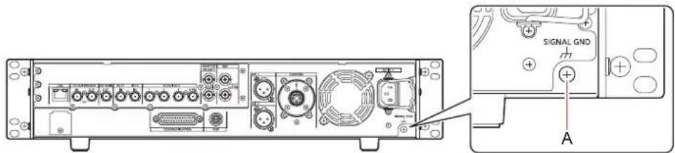
A. [SIGNAL GND] terminal
Handle carefully
- Dropping the unit or subjecting it to a strong impact or vibration may cause a failure or accident.
- Do not allow any foreign objects to enter inside the unit.
Allowing water, metal items, food or drink, or other foreign objects to enter inside the unit may cause a fire or electric shock.
Installation location
- This unit is designed for indoor use only.
- Do not install the unit in a cold place where the temperature drops below 0 °C (32 °F) or in a hot place where the temperature rises above 40 °C (104 °F).
- Avoid installing the unit where it will be exposed to direct sunlight or near an outlet from which hot air is blown out.
- Installing the unit in a location with a lot of humidity, dust, or vibration may result in a failure.
Mounting the unit in a rack
Mounting the rack mount adapters
1. Remove the setting legs (A) secured to the unit.
Remove them using a Phillips screwdriver.
2. Mount the supplied rack mount adapters (B).
- Mounting screws are not supplied. Use mounting screws removed from the unit using a Phillips screwdriver. Tighten the mounting screws for rack mount adapters using a torque of 110 N·m or more.
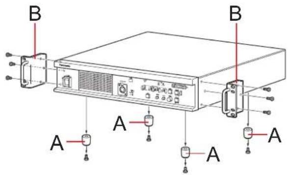
A. Setting legs
B. Rack mount adapters
Mounting the unit in a rack
- Use the unit securely mounted in a standard 19-type rack (depth: 600 mm [23-5/8 inches] or more) compliant with EIA or JIS standards or equivalent.
- Securely fix the unit in place using screws that are appropriate for the rack.
- Be sure to attach a support guide for supporting (A) the rear of the unit. (Provide a support guide that is appropriate for the rack.)
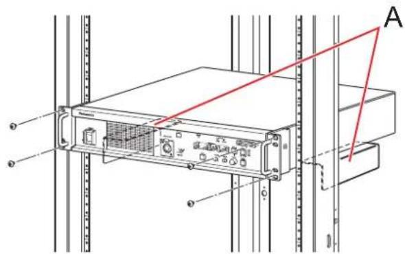
A. Support guide
Mounting positions
In the case of the EIA standard rack

In the case of the JIS standard rack


NOTE
- Do not block the ventilation holes when installing the unit.
Connection
System configuration
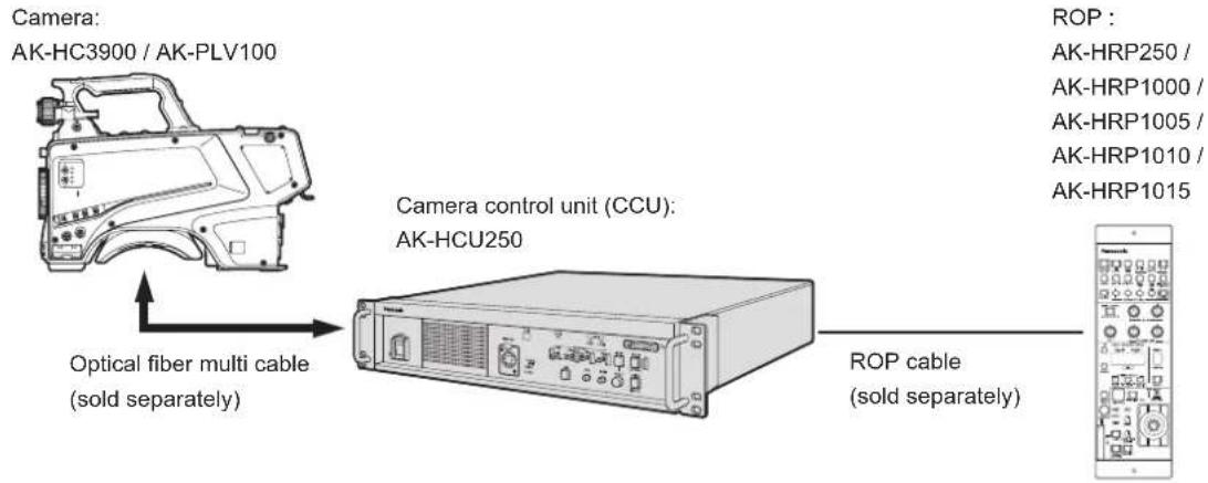
Serial connection
Use the optical fiber multi cable (sold separately) to connect the unit and camera.
Use a ROP cable to connect the unit to the ROP (AK-HRP250 / AK-HRP1000 / AK-HRP1005 / AK-HRP1010 / AK-HRP1015).
For the connection procedure, see "Equipment connections."
→ "Equipment connections" (see page 17)
IP connection
Use the optical fiber multi cable (sold separately) to connect the unit and camera.
Connect the unit to the ROP (AK-HRP250 / AK-HRP1000 / AK-HRP1005 / AK-HRP1010 / AK-HRP1015) via a PoE-compatible switching hub using LAN cables (straight cables: sold separately).
- Read "Network security" before connecting the devices.
- Use a switching hub with PoE support.
For the connection procedure, see "Setting the user account" and "Equipment connections."
→ "Setting the user account" (see page 16)
→ "Equipment connections" (see page 17)
![graph TD A["Camera: AK-HC3900 / AK-PLV100"] -->|Optical fiber multi cable (sold separately)| B["Camera control unit (CCU): AK-HCU250"] B -->|LAN cable (straight cable) (sold separately)| C["Electronic device"] B -->|LAN cable (straight cable) (sold separately)| C D["ROP : AK-HRP250 / AK-HRP1000 / AK…](/content/2026/05/910589/images/66cabe45e14cecce817af5d4974b0dcf2d0c61481e93798dd9d1258182a6145b.jpg)
PoE-compatible switching hub
Setting the user account
In order to connect this unit and the ROP (AK-HRP250 / AK-HRP1000 / AK-HRP1005 / AK-HRP1010 / AK-HRP1015), you will need to register the account that has been registered on the ROP on this unit.
Use the following procedure to register the account on this unit.
Software
To install the software, download User Account Setup Software (AccoutGen) from the following website. (Windows)
https://pro-av.panasonic.net/en/
■User Account Setup Software (AccoutGen)
User account setting of this unit can be set using User Account Setup Software.
Use the User Account Setup Software to set the user accounts in this unit
User account setting of this unit can be set using User Account Setup Software.
- The User Account Setup Software saves user account information to an SD card, so you will need to insert an SD card in preparation.
- We recommend a password for the user account that is 8 characters or more, and that includes at least 3 types of character including upper case, lower case, numerals, and special characters.
- User accounts can also be set from the web screen of this unit.
→ "ROP account settings screen [ROP account setting]" (see page 78)
Procedure for setting with the User Account Setup Software
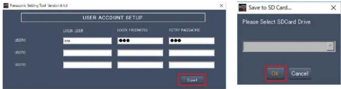
Fig.1 Fig.2
- Start User Account Setup Software.
- Enter the account name in the LOGIN USER field and the password in the LOGIN PASSWORD and RETRY PASSWORD fields.
You can register user accounts for a maximum of 3 people. (Fig.1) - Click the [Export] button. (Fig.1)
- Select the SD card to save to and click [OK]. (Fig.2)
Setting procedure on this unit
- Insert the SD card containing the user account information into this unit.
- Select [ACCOUNT SETTING] in the [MAINTENANCE] menu.
- Select [LOAD].
- Select [EXECUTE].
- Select [YES].
Equipment connections
- Before proceeding with the connections, check that the power of the unit and camera is OFF.
- Use the optical fiber multi cable to connect the unit and camera.
Connect only the AK-HC3900 / AK-PLV100 camera: Do not connect any other model.
- Use a dedicated cable to connect the unit to the ROP.
- When the unit's [POWER] switch is set to ON and then the camera's power is set to ON, the camera can be controlled using the ROP.
- The camera statuses are shown on the picture monitor.
→ "Picture monitor displays" (see page 23)
When you configure the unit's settings by menu operations, the menu screens are displayed on the picture monitor.
→ "Menu operations" (see page 36)
- Before disconnecting the cables from the camera and ROP, turn off the camera's power and then turn off the unit's power.
- When connecting the unit to the ROP using IP connection via a switching hub, use a switching hub that provides PoE support.
- When operating multiple ROPs at the same time with the unit connected using IP connection via a switching hub, the ROP operated last will be given priority.
Camera: AK-HC3900 / AK-PLV100

ROP :
AK-HRP250 /
AK-HRP1000 /
AK-HRP1005 /
AK-HRP1010 /
AK-HRP1015
Parts and their functions
Front panel 1
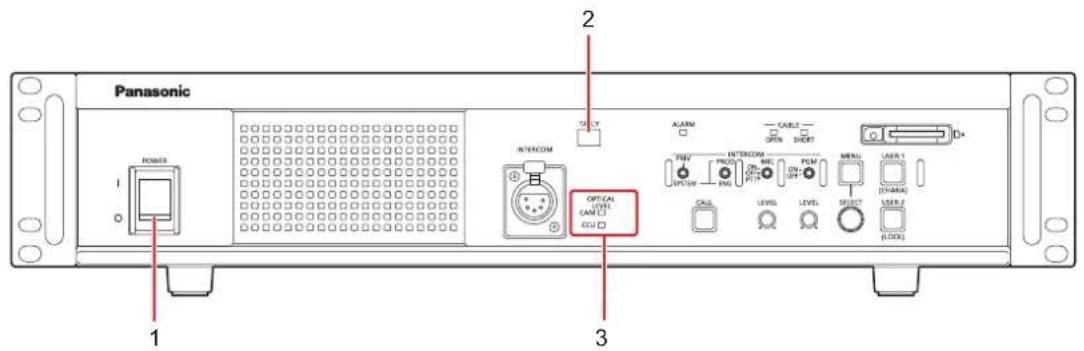
1 [POWER] switch This is the unit's power switch.Move it to the ON position to turn on the power. |
| 2 [TALLY] lamps The lamp remains lit while tally signals (R) are input. |
| 3 [OPTICAL LEVEL] indicators Indicates the reception status of optical transmission.[CAM] indicatorIndicates the reception status on the camera.[CCU] indicatorIndicates the reception status on the CCU. |
Front panel 2
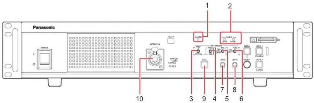
| 1 [ALARM] indicator • [ALARM] indicator | ||
| 2 [CABLE] indicators Lights to indicate | the cable connection status. | |
| • [OPEN] indicatorThis lights when the unit and camera are not connected by the optical fiber multi cable. | ||
| • [SHORT] indicatorThis lights when the cable connecting the unit and camera has been short-circuited. | ||
| 3 | [PRIV/SYSTEM] selector switch | This switch is for selecting the party to call using the intercom.Switch position |
| PRIV: For making private calls between the unit and camera side.SYSTEM: For calling the intercom on the system side and camera side. | ||
| 4 [PROD/ENG] selector switch This switch selects the party to which to speak via the intercom. | ||
| 5 [MIC] switch This switch switches the intercom microphone ON/OFF.Switch position | ||
| ON: The intercom microphone is turned on.OFF: The intercom microphone is turned off.PTT: The intercom microphone is on only while the switch is held down. | ||
| 6 [PGM] switch This switch mixes audio for the intercom.Switch position | ||
| ON: The sound of PGM is mixed with the intercom sound.OFF: The sound of PGM is not mixed with the intercom sound. | ||
| 7 | [INCOM LEVEL] adjustment dial | These controls are for adjusting the volume level of the sound heard through the intercom. |
| 8 | [PGM LEVEL] adjustment dial | This dial adjusts the volume level of the intercom's program audio mix. |
| 9 [CALL] button This button calls the camera and the ROP.During calling, it lights red. | ||
| 10 | [INTERCOM] connector | This connector is for connecting the intercom.This connector enables calls with the intercom line of the camera. |
Front panel 3

| 1 | [MENU] button | When you hold down the [MENU] button, the menu screen is displayed on the picture monitor and the [MENU] button lights.If you hold down the [MENU] button while the menu is displayed, the menu closes and the [MENU] button turns off.→ "Menu operations" (see page 36) |
| 2 | [SELECT] dial This jog dial is for menu screen operations.When the [SELECT] dial is turned clockwise, the cursor moves down; conversely, when it is turned counterclockwise, the cursor moves up.Press the [SELECT] dial to select the menu items.→ "Menu operations" (see page 36) | |
| 3 | [USER1] and [USER2] buttons These buttons are used for assigning functions.Function assignments are selected using [SETUP] in the CCU menu.The following functions are pre-assigned at the factory.[USER1] button: CHARA[USER2] button: LOCK→ "SETUP" (see page 50) | |
| 4 | Memory card slot Insert a memory card (sold separately).A memory card can be used to set this unit.→ "SD CARD" (see page 54) | |
| 5 | Memory card access lamp This is lit while the memory card is being accessed. | |
Rear panel 1
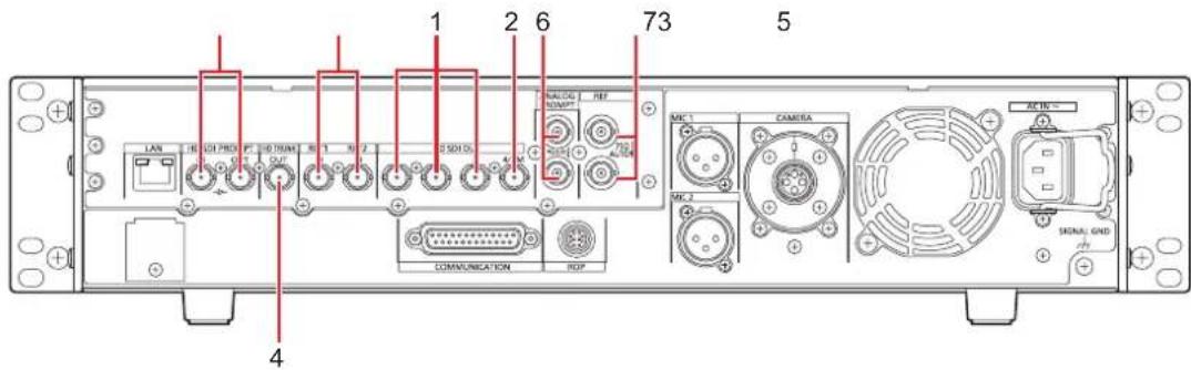
| 1 [HD SDI OUT] connectors [1] to [3] | These connectors (BNC) are for outputting 3G/1.5G-SDI signals. Signals output can be selected from the CCU menu.● Connect with a 5C-FB cable or better. |
| 2 [HD SDI OUT] connector [4/PM] | These connectors (BNC) are for outputting 1.5G-SDI signals. This output is specifically for the picture monitor.● Connect with a 5C-FB cable or better. |
| 3 [HD SDI PROMPT IN] and [HD SDI PROMPT OUT] connectors | These connectors (BNC) are for inputting 3G/1.5G-SDI prompter signals. An active through signal is output from the [HD SDI PROMPT OUT] connector.● 1080/59.94p/50p/59.94i/50i video formats can be input.● Connect with a 5C-FB cable or better. |
| 4 [HD TRUNK OUT] connector | The 3G/1.5G HD SDI TRUNK signals that are input to the camera are output. |
| 5 [RET1 IN] to [RET2 IN] connectors | These connectors (BNC) are for inputting SDI signals for return images in HDTV formats. 3G and 1.5G are recognized automatically.● Connect with a 5C-FB cable or better. |
| 6 [ANALOG PROMPT IN] and [ANALOG PROMPT OUT] connectors | This connector (BNC) is for inputting SD analog composite signals for the prompter. When a cable is not connected to ANALOG PROMPT OUT, the connector is automatically terminated at 75 Ω. Connecting a cable to this connector releases 75 Ω termination. |
7 [REF] connector These connectors (BNC) are for inputting reference signals. Black burst (BB) signals and tri-level sync signals can be input, and the type of signals input is recognized automatically.*1When no cable is connected to the loop-through output connector (B), the connector is automatically terminated at 75 Ω. Connecting a cable to this connector releases 75 Ω termination.When a cable is connected to the loop-through output connector (B), be sure to connect the other end of the cable to a connector.REF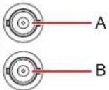 A. Reference signal input connectorB. Loop-through output*1: When the [CCU MODE] is [1080/23.98psF], input 1080/23.98psF (47.95 Hz) tri-level sync signals.For details on supported sync signals for each format, see "G/L specifications."→"G/L specifications" (see page 85) A. Reference signal input connectorB. Loop-through output*1: When the [CCU MODE] is [1080/23.98psF], input 1080/23.98psF (47.95 Hz) tri-level sync signals.For details on supported sync signals for each format, see "G/L specifications."→"G/L specifications" (see page 85) | |
Rear panel 2

| 1 | [LAN] connector | It is the LAN connector (RJ45) for connecting the ROP (AK-HRP250 / AK-HRP1000 / AK-HRP1005 / AK-HRP1010 / AK-HRP1015) with an IP connection.Use a switch hub and connect the devices with a 10BASE-T/100BASE-TX straight cable. This connector is for connecting a personal computer when configuring Web settings.• Connect with a category 5e or better STP (Shielded Twisted Pair) LAN cable. |
| 2 | [COMMUNICATION] connector | This connector is for connecting the intercom signals and tally signals to the external system. |
| 3 [ROP] connector This connector is for connecting a ROP (sold separately). | ||
| 4 | [MIC1] and [MIC2] connectors | These connectors are for outputting the analog signals of microphones 1 and 2 of the camera.The microphone level is 0 dBm/600 Ω. |
| 5 | [CAMERA] connector | This connector is for connecting the optical fiber multi cable (sold separately). |
| 6 Cooling fan This is the unit's cooling fan. | ||
| 7 AC power socket This socket is for inputting AC power.Connect the supplied power cable, and use a 3-prong outlet and ground the unit properly. | ||
| 8 [SIGNAL GND] terminal Connect this to the system ground. | ||
Picture monitor (PM)
Picture monitor displays
Display the camera statuses, warnings, and other information on the picture monitor using the operation panel of the ROP.
Press the [CHARA] button (A) of the ROP to display the desired information.
- When [CHARA] is assigned to the [USER] button on the front panel of the unit (AK-HCU250), the same operation can also be carried out with the [USER] button.
The camera statuses, warnings, and other information are cleared when the [CHARA] button of the ROP is held down.
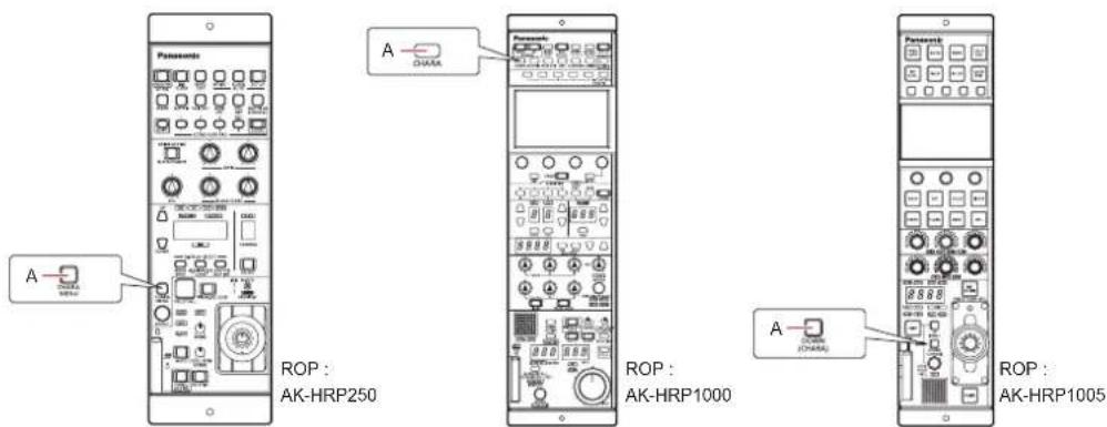
A. [CHARA] button
Transition of displays
When trouble is detected, warning information is automatically displayed on the picture monitor.
Even if status information or operation information is already displayed on the picture monitor when trouble is detected, priority is given to the display of the warning information.
The descending sequence of priority for the displays on the picture monitor is as follows: warning displays → auto displays → status displays → ROP menu displays → CCU menu displays → operation displays → no display.
When the warning information with the highest priority disappears, the warning information with the next highest priority appears.
| Priority Screen | ROP connected | ||
| Yes No | |||
| High↑↓Low | Warning displays Warnings are automatically displayed when trouble is detected.Self-recovery.The warning displays are cleared.Press the [CHARA] button of the ROP No display→(WARNING)→ IRIS →Status displays→ Status1 → Status2 → Status3 → Status4 → Status5 → Status6 → Status7 → IRIS · · ·Hold down the [CHARA] button of the ROP.The warning displays are cleared. | Warnings are automatically displayed when trouble is detected.Self-recovery.The warning displays are cleared.Press the [USER1] button of this unit (This is enabled when [CHARA] is assigned to the button.)When the transition source screen is displayed:The display switches to the transition source screen.When the transition source screen is not displayed:The warning displays are cleared. | |
| Auto displays Automatically displayed Automatically displayed | |||
| Status displays • Perform display operations using the [CHARA] button of the ROP.Press the [CHARA] button of the ROP No display→(WARNING)→ IRIS →Status displays→ Status1 → Status2 → Status3 → Status4 → Status5 → Status6 → Status7 → IRIS · · ·Hold down the [CHARA] button of the ROP.The status displays end. | - | ||
| CCU menu displays• When the camera menu is displayed from the ROP while a menu of the CCU (this unit) is displayed, the menu of the CCU (this unit) disappears. | Display by pressing the menu button on the unit.Operations using the [SELECT] dial on the unit. | Display by pressing the menu button on the unit.Operations using the [SELECT] dial on the unit. | |
| Operation displays Automatically displayed Automatically displayed | |||
| No display -- | |||
Information display
This information is displayed on the picture monitor (PM).
Warning displays
The warning information is displayed when trouble is detected in the unit, camera, or optical fiber multi cable.
- WARNING -
CAM RCV LVL NG
CCU RCV LVL NG
- Warning information displayed is cleared when the status returns to normal.
- To manually clear the warning information display, hold down the [CHARA] button of the ROP.
Information displayed
| Display item Description | |
| CAM RCV LVL NG The level of the optical signal received by the camera is low. | |
| CCU RCV LVL NG The level of the optical signal received by the CCU is low. | |
| CAM FAN NG Trouble with the cooling fan of the camera. | |
| CCU FAN NG Trouble with the cooling fan of the CCU. | |
| CAM HIGH TEMP The temperature of the camera is abnormally high. | |
| CCU HIGH TEMP The temperature of the CCU is abnormally high.If you continue operation even with the message displayed, power supply to the camera may stop as a protective measure. | |
| CAM OVER TEMP Due to overheating, the camera turned OFF automatically as a protective measure. | |
| OVER LOAD The power supply circuit load to the camera exceeded 90%. | |
| POWER CONT ERROR Trouble with the power supply circuit to the camera. | |
| CABLE OPEN | The optical fiber multi cable is not connected. |
| CABLE SHORT | The optical fiber multi cable is shorted.The power supply voltage to the unit dropped momentarily.Power supply to the camera will stop as a protective measure.Turn the unit off immediately, and determine and resolve the problem before turning it back on.The camera is malfunctioning or startup of the camera failed for reasons other than the above. |
| FORMAT NG | The CAM mode and CCU mode do not match. |
| During data transfer (CAM←→ROP) | Data transfer between the camera and ROP is in progress. |
IRIS display
When the information is not displayed on the picture monitor, display it by pressing the [CHARA] button of the ROP.

A. Camera number
B. IRIS F value
C. IRIS level
D. IRIS memory
E. TALLY INFO
- Set each item to be displayed on the [PM VIEW SETTING] screen that can be accessed by selecting [MAINTENANCE] on the CCU menu. However, this screen will not appear if the menu's [IRIS LEVEL] setting is [OFF].
- The IRIS schedule is displayed as follows depending on the setting of [IRIS SCALE] that can be accessed by selecting [MAINTENANCE] > [SETUP].
IRIS SCALE: FULL

IRIS SCALE: 2STOP
- In the IRIS level display, the IRIS F value stored in IRIS memory is indicated at the center (+), and the current IRIS F value is displayed relative to the center as "*".
When the center value (+) and the current IRIS value (*) overlap, the display shows " > * <

- When the IRIS level falls outside either end of the display range, the status is displayed as a flashing ">" or "<".

• TALLY INFO (E)
- Display the R tally in two segments of the upper row and the R or G tally in two segments of the lower row.
- When all R and G tally signals are ON, the upper row is red, and the left segment of the lower row is green.
- When the R and G tally signals are ON, the upper row is red and the lower row is green.
Status displays
From the IRIS display screen, press the [CHARA] button of the ROP to display the "status display screen".
However, when the "IRIS LEVEL" setting is "OFF", the screen will be displayed first if the [CHARA] button of the ROP is pressed when the information is not displayed on the picture monitor.
When the "status display screen" appears, pressing the [CHARA] button of the ROP again displays the status screen.
Pressing the [CHARA] button repeatedly switches display through the status screens in the sequence 1/7 → 2/7 → 3/7 → 4/7 → 5/7 → 6/7 → 7/7 → 1/7 ....
Status display screen

A. Camera number
B. System format
C. Scene file number
Not displayed when SCENE FILE is set to OFF.
D. Gain value
E. HDR information
F. COLORIMETRY information
G. Extender information
H. F.DROP information
I. Shutter value
J. Zoom position
K. Focus position
L. Optical signal reception status
M. ND filter value
N. Color temperature
O. IRIS value
P. TALLY INFO
- Set each item to be displayed on the [PM VIEW SETTING] screen that can be accessed by selecting [MAINTENANCE] on the CCU menu.
- The camera format indicates the format of the signal output from the camera.
-
Pressing the [CHARA] button of the ROP from the status display screen displays the "status screen".
• TALLY INFO (L) -
Display the R tally in two segments of the upper row and the R or G tally in two segments of the lower row.
- When all R and G tally signals are ON, the upper row is red, and the left segment of the lower row is green.
- When the R and G tally signals are ON, the upper row is red and the lower row is green.
Q. V-LOG information
Status displays (page 1 of 7)
| 1/7 -Status1- | ||
| HLG MODE | VAR | |
| SDR MODE | VAR | |
| HLG B.GAMMA | ON | |
| HLG KNEE | ON | |
| SDR CONV GAIN | 0 | |
| SDR CONV POINT | 0 | |
| SDR CONV SLOPE | 0 | |
| Item Display range | Remarks | |
| HLG MODE FIX | VAR | The HLG mode is displayed here. |
| SDR MODE FIX | VAR | The SDR mode is displayed here. |
| HLG B.GAMMA OFF | ON | The status of black gamma when HLG is enabled is displayed here. |
| HLG KNEE OFF | ON | The status of knee when HLG is enabled is displayed here. |
| SDR CONV GAIN -12 | -11-10-9-8-7-6-50 | The gain value when HDR video is converted to SDR video is displayed here. |
| SDR CONV POINT 0 to 100 The video level to start compression for SDR video is displayed here. | ||
| SDR CONV SLOPE 0 to 127 The slope to compress video signals is displayed here. | ||
Status displays (page 2 of 7)
| 2/7 -Status2- | |
| CAM No. | 1 |
| BLACK SHADING | OFF |
| WHITE SHADING | OFF |
| FLARE | OFF |
| GAMMA | OFF |
| BLACK GAMMA | OFF |
| KNEE | OFF |
| WHITE CLIP | OFF |
| DRS SW | OFF |
| MATRIX | OFF |
| SHUTTER | OFF |
| Item Display range | Remarks | |
| CAM No. 1 to 99 The camera number is displayed here. | ||
| BLACK SHADING OFF | ON | The status of the black shading is displayed here. |
| WHITE SHADING OFF | ON | The status of the white shading is displayed here. |
| FLARE OFF | ON | The status of the FLARE is displayed here. |
| GAMMA OFF | ON | The status of the gamma correction is displayed here. |
| BLACK GAMMA OFF | ON | The status of the black gamma is displayed here.This function changes the amplification rate of the video signals in the low-brightness areas. |
| KNEE OFF | ON | The status of the knee function is displayed here.This function attenuates that part of the video signal that exceeds the prescribed level (knee point) to minimize saturation. |
| WHITE CLIP OFF | ON | The status of the white clip function is displayed here. |
| DRS SW OFF | ON | The status of the DRS SW is displayed here. |
| MATRIX OFF | ON | The status of the matrix function is displayed here.This function compensates the saturation and hue. |
| SHUTTER | Setting values on camera | The speed of the electronic shutter is displayed here.For the setting values, refer to the Operating Instructions for the camera. |
Status displays (page 3 of 7)
When AK-PLV100 is connected, if the setting on AK-PLV100 of [MODE] in [SWITCH MODE] → [GAIN SETTING] is [ISO], [M.GAIN] becomes [ISO SELECT] and [M.GAIN VAR] becomes [ISO].
| 3/7 -Status3- | |
| GAMMA MODE | FLIKE1 |
| M.GAIN | 36dB |
| M.GAIN VAR | -2.9dB |
| DETAIL | OFF |
| SKIN TONE DETAIL | OFF |
| DC DETAIL | OFF |
| DC SKIN TONE DETAIL | OFF |
| ND FILTER | **** |
| LENS EXTENDER | 1.0 |
| AUTO IRIS | OFF |
| SCENE FILE | SCENEO |
| 3/7 -Status3- | ||
| GAMMA MODE | FLIKE1 | FLIKE1 |
| ISO SELECT | NATIVE | NATIVE |
| ISO 800 | 800 | |
| DETAIL OFF | OFF | |
| SKIN TONE DETAIL | OFF | OFF |
| DC DETAIL | OFF | OFF |
| DC SKIN TONE DETAIL | OFF | OFF |
| ND FILTER | **** | |
| LENS EXTENDER | 1.0 | 1.0 |
| AUTO IRIS | OFF | OFF |
| SCENE FILE | SCENEO | SCENEO |
When [MODE] is [dB] When [MODE] is [ISO]
| Item Display range | Remarks | |
| GAMMA MODE HD | FILMLIKE1FILMLIKE2FILMLIKE3FILM RECVIDEO REC | The selected gamma type is displayed here. |
| M.GAIN -6dB to 36dB The gain increase value is displayed here.ISO SELECT NATIVE / 800 / 2500 The ISO operation set on AK-PLV100 is displayed here. | ||
| M.GAIN VARISO | -6dB to 36dB The gain offset value is displayed here.200 to 25600 The ISO value set on AK-PLV100 is displayed here. | |
| DETAIL | OFFON | The status of DETAIL is displayed here. |
| SKIN TONE DETAIL | OFFON | The status of SKIN TONE DETAIL is displayed here. |
| DC DETAIL | OFFON | The status of DC DETAIL is displayed here.• Displayed only when the SYSTEM FORMAT is UHD. |
| DC SKIN TONE DETAIL | OFFON | The status of DC SKIN TONE DETAIL is displayed here.• Displayed only when the SYSTEM FORMAT is UHD. |
| ND FILTER | **** | The names of the ND filters are displayed here.• Indicates the names (4 letters each) corresponding to ND filters 1 to 5.• The names configured in the CCU screen appear. |
| LENS EXTENDER | 1.02.0 | The magnification of the lens extender is displayed here. |
| AUTO IRIS | OFFON | The status of the auto IRIS function is displayed here.• This is not displayed when AK-PLV100 is connected. |
| SCENE FILE | OFF---1 to 8 | The selected scene file is displayed here. |
Status displays (page 4 of 7)
4/7 -Status4-
| RETURN1 | RET1 |
| RETURN2 | RET2 |
| Item Display range | Remarks | |
| RETURN1 RET1 | RET2 | The input assignment for return signals is displayed here. |
| RETURN2 |
Status displays (page 5-1 of 7)

| Item Display range Remarks | ||
| HD SDI OUTPUT1 1080p/1080i/1080-29.97PsF/ | The output formats for connectors HD SDI OUTPUT1, HD SDI OUTPUT2, and HD SDI OUTPUT3 are displayed here. | |
| HD SDI OUTPUT2 | 1080-23.98PsF/1080-23.98p over 59.94i/720p/1080p-HDR/1080i-HDR/ | |
| HD SDI OUTPUT3 | 1080-29.97PsF-HDR/1080-23.98PsF-HDR/1080-23.98p over 59.94i-HDR/1080-25PsF/1080-25PsF-HDR | |
| HD SDI OUTPUT4 1080i/720p The output format for connectors HD SDI | OUTPUT4 isdisplayed here. | |
Status displays (page 5-2 of 7)

| Item Display range Remarks | ||
| UHD/HD SDI OUTPUT1-4 | 2160p/2160-29.97PsF/2160-29.97p/2160-23.98PsF/2160-23.98p/2160p-HDR/2160-29.97PsF-HDR/2160-29.97p-HDR/2160-23.98PsF-HDR/2160-23.98p-HDR/2160-25PsF-HDR/2160-25p-HDR/1080p/1080i/1080-29.97PsF/1080-23.98PsF/1080-23.98p over 59.94i/1080-23.98p over 59.94i-HDR/720p/1080p-HDR/1080i-HDR/1080-29.97PsF-HDR/1080-23.98PsF-HDR/1080-25PsF/1080-25PsF-HDR | The output formats for UHD/HD SDI OUTPUT1 to 4 are displayed here. |
| UHD/HD SDI OUTPUT1 | 1.5G/3G/6G/12G/UHD/no signal The output formats for UHD/HD SDI OUT1 to 4 are displayed here. | |
| UHD/HD SDI OUTPUT2 | ||
| UHD/HD SDI OUTPUT3 | ||
| UHD/HD SDI OUTPUT4 | ||
| UHD OUTPUT FORMAT | INTERLEAVE SQUARE | The signal format of UHD is displayed here. |
| UHD COLORIMETRY BT | .709BT.2020 | The status of COLORIMETRY is displayed here. |
| UHD GAMUT NORMAL | WIDE_G2 | The status of GAMUT is displayed here. |
Status displays (page 6 of 7)
6/7 -Status6-
HD TRUNK
HD TRUNK
| Item Display range | Remarks | |
| HD TRUNK HD TRUNK The signal to | be output from the [HD TRUNK OUT] connector is displayed here. | |
Status displays (page 7 of 7)
7/7 -Status7-
BUTTON ASSIGN
USER1
CHARA
USER2
MENU/USER1 LOCK
HOURS CCU
H
CABLE OPEN
CABLE SHORT
CAM RECEIVE LEVEL
■ ■ ■ ■ ■
CCU RECEIVE LEVEL
■ ■ ■ ■ ■
VERSION
XX.XX-XXXX-XX.XX
| Item Display range | Remarks | |
| BUTTON ASSIGN USER1 NONE | CHARABARSCLEAN | The function assigned to the [USER1] button is displayed here. |
| BUTTON ASSIGN USER2 NONE | CHARAMENU/USER1 LOCKBARSCLEAN | The function assigned to the [USER2] button is displayed here. |
| HOURS CCU *****H Cumulative CCU operating time is displayed here. | ||
| CABLE OPEN (Off) This item flashes when the optical fiber multi cable is not connected. | ||
| CABLE SHORT (Off) This item flashes when the optical fiber multi cable is short-circuited. | ||
| CAM RECEIVE LEVEL | ■■■■■ | The level of the optical signals received by the camera is displayed in 5 gradations. |
| CCU RECEIVE LEVEL | ■■■■■ | The level of the optical signals received by the unit is displayed in 5 gradations. |
| VERSION - - - The unit's software version is displayed here. | ||
Operation displays
The operation displays appear at the bottom of the screen for approx. 4 seconds when any of the following operations have been performed with the operation panel of the ROP.
- Master gain change
• Electronic shutter change - Lens extender change
- Scene file change
- REF LOAD is changed
- FILTER is changed
The display time can be changed from [MAINTENANCE] menu > [PM OPERATION STATUS] > [STATUS DISP TIME].
MASTER GAIN 12dB
| Item Display range | Remarks | |
| MASTER GAIN Setting values on | camera | The master gain value is displayed here.· For the setting values, refer to the Operating Instructions for the camera. |
| SHUTTER Setting values on | camera | The speed of the electronic shutter is displayed here.· For the setting values, refer to the Operating Instructions for the camera. |
| LENS EXT 1.0 | 2.0 | The magnification of the lens extender is displayed here.· When the magnification of the lens extender is set to 2x, [2.0] is displayed. Otherwise, [1.0] is displayed. |
| SCENE FILE OFF | 1 to 8 | This indicates the scene file name. |
| REF LOAD FACTORY | USER1 to USER3 REF1 to 3 | This indicates the reference file that was loaded via reference call recalling. |
| FILTER **** | (ND/CC filter name) | The names of the ND filter/CC filters are displayed here. |
Auto displays
When the following operation is performed while no menu is displayed on the picture monitor, information on the operation performed appears at the bottom of the screen.
- AWB (Auto White Balance) function
• ABB (Auto Black Balance) function
The display is cleared 4 seconds after the operations are completed.
If the operations cannot be completed, they will remain displayed until the NG (error) items of the AUTO function are released.
The display time can be changed from [MAINTENANCE] menu > [PM OPERATION STATUS] > [STATUS DISP TIME].
AWB: ACTIVE
While viewing the menu screen of the picture monitor, operate the [MENU] button and [SELECT] dial on the front panel.
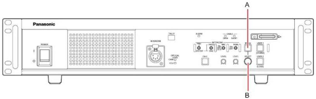
A. [MENU] button
B. [SELECT] dial
Displaying and hiding the menus
Menus are displayed or hidden by the following procedure.
1. Press the [MENU] button.
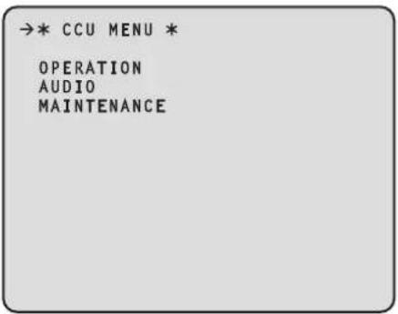
The [MENU] button lights and the menu (CCU MENU) is displayed.
If you press the [MENU] button while the menu is displayed, the menu closes and the [MENU] button turns off.
![graph LR A["Menu"] -->|Press| B["CCU MENU *"] B --> C["OPERATION\nAUDIO\nMAINTENANCE"]](/content/2026/05/910589/images/e2b75b91a2134d41843d919241868f7db7902e4611998622aafc9da0f95a0066.jpg)
Basic menu operations
Menu items are selected and set by the following procedure.
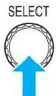
1. Turn the [SELECT] dial while in the [CCU MENU], select [OPERATION] or [MAINTENANCE], and then press the [SELECT] dial.
A list of menu items included in the selected item ([OPERATION] or [MAINTENANCE]) is displayed.
- When the [SELECT] dial is turned clockwise, the cursor moves down; conversely, when it is turned counterclockwise, the cursor moves up.
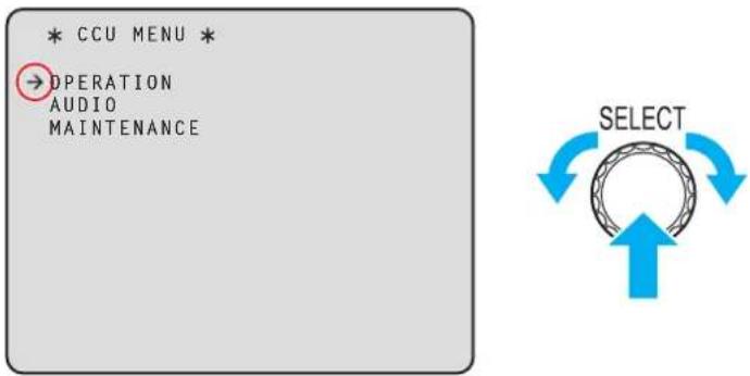
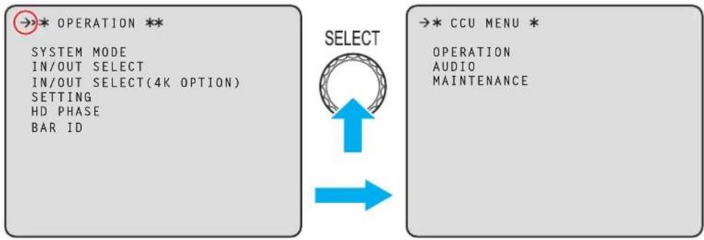
2. Turn the [SELECT] dial to move the cursor to the menu item you want to set, and then press the [SELECT] dial.

The setting screen one level below the selected menu item appears.

- Moving the cursor to the menu title and then pressing the [SELECT] dial redisplays [CCU MENU].
3. Turn the [SELECT] dial to move the cursor to the menu item you want to set, and then press the [SELECT] dial.
The setting value of the selected menu item starts flashing and you can change it.
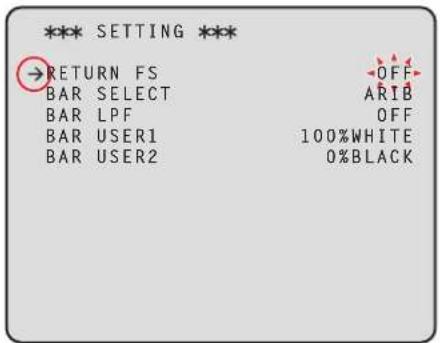
![graph TD A["SELECT"] --> B["Loop"] B --> C["Arrow Up"] B --> D["Arrow Down"] B --> E["Arrow Left"]](/content/2026/05/910589/images/10879749bbbb18e2e53faa573d7f1340a18c39fad254f3b00e439f13e156f227.jpg)
4. Turn the [SELECT] dial to change the value, and then press the [SELECT] dial.
Turning the [SELECT] dial changes the setting value and pressing the [SELECT] dial confirms the setting value.

![PANASONIC AK-HCU250PSJ - Turn the [SELECT] dial to change the value, and then press the [SELECT] dial. - 2](/content/2026/05/910589/images/e33b91ee7188ca97d475c91bf723e9823ab274ad701a386c9738cacd286525da.jpg)
When the setting value is confirmed and the flashing stops, you can move the cursor.
With some menu items, setting changes become effective while the setting value is in the flashing state; with others, changes become effective when the [SELECT] dial is pressed to confirm the setting value.
Operation with menu items that have multiple setting items on one line
1. Turn the [SELECT] dial to move the cursor to the menu item you want to set, and then press the [SELECT] dial.
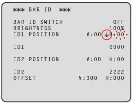
The cursor becomes "↓" and you can use the [SELECT] dial to move the cursor to a setting item in the selected menu item.

![graph TD A["SELECT"] --> B["Process Step"] B --> C["Return Path"] C --> A](/content/2026/05/910589/images/cacc9fedf9d44316983017b84941a2f3d5fef3994674a8e24a98ecd220c00fe2.jpg)
2. Turn the [SELECT] dial to move the cursor to the item you want to set, and then press the [SELECT] dial.
The setting value of the selected item starts flashing and you can change it.
![graph TD A["SELECT"] --> B["Process Step"] B --> C["Return Path"] C --> A](/content/2026/05/910589/images/006ceef3a76c8aca4612987d15927d67f478d2705c9e30537a6bd67b2cfc18ae.jpg)
3. Turn the [SELECT] dial to change the value, and then press the [SELECT] dial.
Turning the [SELECT] dial changes the setting value and pressing the [SELECT] dial confirms the setting value.

![graph TD A["SELECT"] --> B((Circular Node)) B --> C["Blue Arrow Down"] B --> D["Blue Arrow Up"]](/content/2026/05/910589/images/929ab5d85809f8a37eb4950a1a1c412386fa5169658edc02ac503990f3b37e45.jpg)
When the setting value is confirmed and the flashing stops, you can move the cursor.
If you press the [SELECT] dial while the cursor is on the left of a menu item, the cursor becomes “→” and you can select the menu item.

![PANASONIC AK-HCU250PSJ - Turn the [SELECT] dial to change the value, and then press the [SELECT] dial. - 4](/content/2026/05/910589/images/42c0e3a4903215890fcee0646f06583ea8f3bd73d042b0003db4d76f715277b3.jpg)
Text input
- Turn the [SELECT] dial to move the cursor to the menu item where text is to be input, and then press the [SELECT] dial.
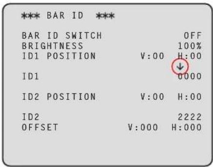
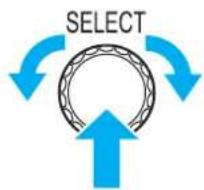
The cursor display changes as indicated by "↓". By turning the [SELECT] dial, you can move the cursor to the next (previous) character position.
- Turn the [SELECT] dial to move the cursor to position where a character is to be input, and then press the [SELECT] dial.
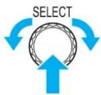
The selected character starts flashing and you can change it.

- Turn the [SELECT] dial to change the character, and then press the [SELECT] dial.
Turning the [SELECT] dial changes characters, and pressing the [SELECT] dial confirms character changes.


When a character has been input and the flashing stops, you can move the cursor.
If you press the [SELECT] dial while the cursor is on the left of a menu item, the cursor becomes “→” and you can select the menu item.


NOTE
- Turning the [SELECT] dial clockwise while pressing it increases the speed at which the number increases (turning it counterclockwise decreases the number). Turning the dial more increases the speed even more. This operation is effective for making a large change to a value when the setting width is large (e.g., IP address or port number).
Menu composition
This is the first screen displayed when you press the [MENU] button.
Select one of the menus.
| Item Content Details page | ||
| OPERATION Makes settings for items such as the system format and input and output. | →“OPERATION” (see page 43) | |
| AUDIO Makes AUDIO related settings. | →“AUDIO” (see page 47) | |
| MAINTENANCE Makes MAINTENANCE related settings. | →“MAINTENANCE” (see page 49) | |
OPERATION
This is the selection screen for the OPERATION menu.
| Item Content Details page | ||
| SYSTEM MODE Makes settings for items such as the system frequency. | → "SYSTEM MODE" (see page 43) | |
| IN/OUT SELECT Sets the external input/output and the operation mode for each connection. | → "IN/OUT SELECT" (see page 44) | |
| IN/OUT SELECT(4K OPTION) Sets the external input/output and the operation mode for each connection when a 4K OPTION board is connected. | → "IN/OUT SELECT(4K OPTION)" (see page 44) | |
| SETTING Makes settings for items such as the color bar and delay time for the return signal. | → "SETTING" (see page 45) | |
| HD PHASE Makes Genlock phase settings. | → "HD PHASE" (see page 45) | |
| BAR ID Makes settings related to the IDs superimposed on color bar. | → "BAR ID" (see page 46) | |
SYSTEM MODE
This is the selection screen for the SYSTEM MODE menu.
____ indicates factory default settings.
| Item Setting value | Setting details | ||
| FORMAT | 1080/59.94p*1 1080/29.97PsF1080/23.98PsF1080/23.98p over 59.94i720/59.94p2160/59.94p2160/29.97PsF2160/29.97p2160/23.98PsF2160/23.98p 1080/50p*2 1080/25PsF720/50p2160/50p2160/25PsF2160/25p | Sets the system format.The 4K (2160) format is available for selection only when the 4K OPTION board is fitted. | |
| CAMERA NUMBER | 1 to 99 | Sets the camera number displayed on the camera, in the CCU status, and on the ROP. | |
| HDR SW | OFFON | Enables/disables the HDR mode. | |
| HD SDI OUTPUT3(HDR) | OFFON | Enables/disables the HDR mode for HD SDI OUTPUT3. | |
| HD SDI OUTPUT1&2(HDR) | OFFON | Enables/disables the HDR mode for HD SDI OUTPUT1&2.Enabled only when the 4K OPTION board is fitted. | |
*1: AK-HCU250P/250PS
*2: AK-HCU250E/250ES
IN/OUT SELECT
This is the selection screen for the IN/OUT SELECT menu.
____ indicates factory default settings.
| Item Setting | value Setting details | |
| SDI OUTPUT1&2 | 3G 1.5G | Sets the format of the signal output from SDI1&2.Fixed to 1.5G when SYSTEM 720p. |
| SDI OUTPUT3 | 3G 1.5G | Sets the format of the signal output from SDI3.Fixed to 1.5G when SYSTEM 720p. |
| 3G SDI | -A -B | Sets the output format when SDI is outputting 3G.Output to the OPTION board is also enabled when the 4K OPTION board is fitted. |
IN/OUT SELECT(4K OPTION)
Displayed only when the 4K OPTION board is fitted.
____ indicates factory default settings.
| Item Setting | value Setting details | |
| UHD/HD SDI OUT(1-4) | 1.5G3G6G12GUHD | Sets the format of the signal output from UHD/HD SDI OUT.Fixed to 1.5G when [FORMAT] is 720p.Switchable between 1.5G and 3G when [FORMAT] is [1080/59.94p] or [1080/50p]. Fixed to 1.5G when [FORMAT] is [1080/29.97PsF], [1080/23.98PsF], or [1080/25PsF].Switchable between UHD and 12G when [FORMAT] is [2160/59.94p] or [2160/50p]. Fixed to UHD when [FORMAT] is [2160/29.97PsF], [2160/23.98PsF], or [2160/25PsF].Switchable between UHD and 6G when [FORMAT] is [2160/29.97p], [2160/23.98p], or [2160/25p]. |
| SDI OUT1 | The content set in | UHD/HD SDI OUT(1-4) is displayed.The display is "no signal" when there is no output. |
| SDI OUT2 | ||
| SDI OUT3 | ||
| SDI OUT4 | ||
| UHD OUTPUT FORMAT | SQUAREINTERLEAVE | Sets the type of signal output from SDI when UHD.The selection item is enabled only when [FORMAT] is UHD.Fixed to SQUARE when [FORMAT] is [2160/29.97PsF], [2160/23.98PsF], or [2160/25PsF].When [FORMAT] is [2160/29.97P], [2160/23.98P], or [2160/25P] and INTERLEAVE is selected, UHD/HD SDI will be LEVEL B. |
| COLORIMETRY | BT.709BT.2020 | Switches the Y/C conversion coefficient.The selection item is enabled only when [FORMAT] is UHD. |
| GAMUT | NORMALWIDE_G2 | Switches the color gamut.The selection item is enabled only when [FORMAT] is UHD. |
SETTING
This is the selection screen for the SETTING menu.
____ indicates factory default settings.
| Item Setting | value Setting details | |
| RETURN FS | ONOFF | Set the delay mode for the HD return signals. |
| BAR SELECT | STDSMPTEARIBEIAJ | Sets the color bar signal. |
| BAR LPF | OFF3TAP5TAP7TAP9TAP | Sets the filter to be applied to the color bar signal. |
| BAR USER1 | 75%WHITE100%WHITE+I_SIGNAL-I_SIGNAL | When the color bar is ARIB, the settings for BAR USER1 are selected. |
| BAR USER2 | 0%BLACK+Q_SIGNAL | When the color bar is ARIB, the settings for BAR USER2 are selected. |
HD PHASE
This is the selection screen for the HD PHASE menu.
____ indicates factory default settings.
| Item Setting value Setting details | ||
| HD H COARSE | -127 to 0 to +127 Makes | broad settings for the horizontal phase for GL HD REF. |
| HD H FINE -100 to 0 to + | 100 Makes detailed settings for the horizontal phase for GL HD REF. | |
| V ADVANCE | -3 / -2 / -1 / 0 | Set the vertical phase of this unit in relation to the vertical phase of the REF signal.The larger the negative value, the larger the advance.The setting unit varies depending on [FORMAT].When the mode is [720/59.94p] or [720/50p], the setting unit is 1H of [720p].When the mode is [1080/23.98PsF], the setting unit is 1H of [1080/23.98PsF].Otherwise, the setting unit is 1H of [1080/59.94i] or [1080/50i]. |
BAR ID
This is the selection screen for the BAR ID menu.
____ indicates factory default settings.
| Item Setting | value Setting details | |
| BAR ID SWITCH | ONOFF | Shows/hides the ID superimposed on the color bars. |
| BRIGHTNESS | 0 to 100% Sets the | luminance for the ID display. |
| ID1 POSITION V | 0 to 05 Sets the vertical position for the start of the ID1 display. | |
| ID1 POSITION H | 0 to 15 Sets the horizontal position for the start of the ID1 display. | |
| ID1 | ##(Max. 16 characters) | Set camera ID1 CHARacters which can be used:Alphanumeric characters, spaces, ! # % & ' ( ) * + , - . / : ; <= > ? [ ] _ ~If "###" is input, that portion is replaced with the camera number (1 to 15) being managed by the CCU. |
| ID2 POSITION V | 0 to 05 Sets the vertical position for the start of the ID2 display. | |
| ID2 POSITION H | 0 to 15 Sets the horizontal position for the start of the ID2 display. | |
| ID2 | Spaces(Max. 16 characters) | Set camera ID2 CHARacters which can be used:Alphanumeric characters, spaces, ! # % & ' ( ) * + , - . / : ; <= > ? [ ] _ ~If "###" is input, that portion is replaced with the camera number (1 to 15) being managed by the CCU. |
| OFFSET V | 00 to 89 Specify the origin (upper left) in the vertical direction of the character drawing area in pixels. | |
| OFFSET H | 00 to 79 Specify the origin (upper left) in the horizontal direction of the character drawing area in pixels. | |
AUDIO
This is the selection screen for the AUDIO menu.
| Item Content Details page | ||
| MIC OUT Makes settings for microphone output. | → "MIC OUT" (see page 47) | |
| CCU INTERCOM TALK Makes settings for the microphone of the intercom. | → "CCU INTERCOM TALK" (see page 47) | |
| INTERCOM Makes settings for the intercom. | → "INTERCOM" (see page 48) | |
| PGM Makes settings for PGM. | → "PGM" (see page 48) | |
MIC OUT
This is the selection screen for the MIC OUT menu.
____ indicates factory default settings.
| Item Setting value | Setting details | |
| MIC1 OUT LV | -40dB to 0dB to +20dB This adjusts the analog output level for MIC1. | |
| MIC2 OUT LV | -40dB to 0dB to +20dB This adjusts the analog output level for MIC2. | |
CCU INTERCOM TALK
This is the selection screen for the CCU INTERCOM TALK menu.
____ indicates factory default settings.
| Item Setting value | Setting details | |
| MIC TYPE | DYNECMCBN | Select the type of intercom microphone. |
| MIC POWER | ONOFF | Set the power supply of the intercom microphone to ON or OFF. |
| MIC GAIN | -40dB to 0dB to +12dB(1dB Step) | This is the volume control of the intercom microphone. |
| SIDE TONE | OFF-36dB to -6dB to 0dB | This is the side tone volume control of the intercom microphone. |
INTERCOM
This is the selection screen for the INTERCOM menu.
____ indicates factory default settings.
| Item Setting value | Setting details | |
| 4W/RTS | 4W/RTS | Select the intercom voice I/O method. |
| 4W INPUT LEVEL | -40dB to 0dB to +20dB (1dB Step) | Switch the 4W (intercom) input level. |
| 4W OUTPUT LEVEL | -40dB to 0dB to +20dB (1dB Step) | Switch the 4W (intercom) output level. |
| RTS INPUT LEVEL | -40dB to 0dB to +20dB (1dB Step) | Switch the RTS (intercom) input level. |
| RTS OUTPUT LEVEL | -40dB to 0dB to +20dB (1dB Step) | Switch the RTS (intercom) output level. |
| RTS CANCEL LEVEL -20.0dB to | +20.0dB(0.5dB Step) | Switch the RTS (intercom) I/O cancellation level. |
PGM
This is the selection screen for the PGM menu.
____ indicates factory default settings.
| Item Setting value | Setting details | |
| PGM GAIN | 0dB20dB | Switch the PGM input gain. |
MAINTENANCE
This is the selection screen for the MAINTENANCE menu.
| Item Content Details page | ||
| START UP Sets the behavior when the unit's power is turned on. | → “START UP” (see page 49) | |
| SETUP Sets the SW&BUTTON and various connection related settings. | → “SETUP” (see page 50) | |
| ND NAME Sets the ND filter name. | → “ND NAME” (see page 50) | |
| NETWORK Makes settings for establishing IP connections. | → “NETWORK” (see page 51) | |
| VERSION Displays the version. | → “VERSION” (see page 52) | |
| PM VIEW SETTING(1/2) Sets what is displayed on the PM. | → “PM VIEW SETTING(1/2)” (see page 52) | |
| PM VIEW SETTING(2/2) Sets what is displayed on the PM. | → “PM VIEW SETTING(2/2)” (see page 53) | |
| PM OPERATION STATUS Sets what is displayed on the PM when there is a change in status. | → “PM OPERATION STATUS” (see page 53) | |
| SYSTEM Initializes the unit and displays connection status with the ROP. | → “SYSTEM” (see page 54) | |
| SD CARD Operations on SD cards. | → “SD CARD” (see page 54) | |
| ACCOUNT SETTING Makes settings for user accounts. | → “ACCOUNT SETTING” (see page 54) | |
| UPDATE | This is the page for updating the software version. | → “UPDATE” (see page 55) |
START UP
This is the selection screen for the START UP menu.
____ indicates factory default settings.
| Item | Setting value | Setting details |
| CAM POWER | OFFONREMOTE | Sets the camera power control when the unit's power is turned on.OFFThe power of the camera will not come on even if the power of this unit is turned on. In this case, you will need to switch "HEAD POWER" on the ROP control panel to ON.ONThe camera's power will come on when the unit's power is turned on.REMOTEThe camera's power will come on when the unit's power is turned off. |
| VF POWER | OFFONREMOTE | Sets the viewfinder power control when the unit's power is turned on.OFFThe viewfinder's power will not come on even when the unit's power is turned on. In this case, "VF POWER" must be set to ON on the operation panel of the ROP.ONTurning on the power of this unit also turns on the power of the viewfinder.REMOTEThe camera's power will come on when the unit's power is turned off. |
| CONNECT MODE | HC3900PLV100 | Selects the camera to be connected to the unit.HC3900Connects to AK-HC3900.PLV100Connects to AK-PLV100. |
SETUP
This is the selection screen for the SETUP menu.
____ indicates factory default settings.
| Item Setting value Setting details | ||
| IRIS SCALE | FULL2STOP | Set the IRIS display range of the status display screen. |
| CABLE CONNECTION | HYBRIDFIBER | Sets the cable used to connect the camera.HYBRIDSelect this when connecting the camera using an optical fiber multi cable.FIBERSelect this when connecting the camera using only optical fiber.When [FIBER] is selected, power will not be supplied to the camera. In addition, the "OPEN" and "SHORT" errors will not be displayed. |
| USER BUTTON1 | NONECHARABARS | Sets the function to be assigned to the [USER1] button on the front panel.NONENo assignmentCHARACharacter display, operationBARSColor bar ON/OFF |
| USER BUTTON2 | NONECHARAMENU/USER1LOCKBARS | Sets the function to be assigned to the [USER2] button on the front panel.NONENo assignmentCHARACharacter display, operationMENU/USER1 LOCKInvalidate [MENU] button, [USER1] button(Function is assigned, but nothing happens when button pressed.)BARSColor bar ON/OFF |
| TALLY | MAKEV | Select the input format for the TALLY signal.MAKEWhen the TALLY IN H terminal and the TALLY IN C terminal are OPEN, then TALLY=OFF. When they are MAKE, then TALLY=ON.The TALLY IN H terminal is internally pulled up to +5 V with a 2.2 K resistor through a protective diode. The maximum current is 20 mA or less.VWhen voltage is applied to the TALLY IN H terminal, TALLY is ON, and when voltage is not applied, TALLY is OFF. Connect TALLY IN C to GND.A resistor of about 12.4 kΩ is inserted between TALLY IN H and TALLY IN C. The maximum voltage that can be applied is 24 V, and the maximum current is 20 mA. |
ND NAME
This is the selection screen for the ND NAME menu.
| Item Setting value Setting details | |
| ND FILTER1 NAME 5 characters Sets the name of the ND filter 1 (maximum of 5 characters). | |
| ND FILTER2 NAME 5 characters Sets the name of the ND filter 2 (maximum of 5 characters). | |
| ND FILTER3 NAME 5 characters Sets the name of the ND filter 3 (maximum of 5 characters). | |
| ND FILTER4 NAME 5 characters Sets the name of the ND filter 4 (maximum of 5 characters). | |

NOTE
- The name set here is displayed in the status display
Characters which can be used:
Alphanumeric characters, spaces, ! # % & ' ( ) * + , - . / : ; <= > ? [ ] _ \~
NETWORK
This is the selection screen for the NETWORK menu.
NETWORK(1/2)
This is the setting screen for the NETWORK(1/2) menu.
____ indicates factory default settings.
| Item Setting value Setting details | ||
| IP ADDRESS | (Factory setting:192.168.0.20) | Set the IP address. |
| SUBNETMASK | (Factory setting:255.255.255.0) | Set the subnet mask. |
| DEFAULT GATEWAY | (Factory setting:192.168.0.1) | Set the default gateway. |
| HTTP PORT | 1 to 80 to 65535 Sets the PORT number used for HTTP.[A042]  The following port numbers cannot be set because they are used by this unit:20, 21, 23, 25, 42, 53, 67, 68, 69, 110, 123, 161, 162, 443, 546, 547, 554, 995, 5960 to 5985, 7960 to 8060, 10669, 10670, 10672, 49152, 49200 to 49299, 59000 to 61000 The following port numbers cannot be set because they are used by this unit:20, 21, 23, 25, 42, 53, 67, 68, 69, 110, 123, 161, 162, 443, 546, 547, 554, 995, 5960 to 5985, 7960 to 8060, 10669, 10670, 10672, 49152, 49200 to 49299, 59000 to 61000 | |
| HTTPS PORT | 1 to 443 to 65535 Sets the PORT number used for HTTPS.[ATK4]  The following port numbers cannot be set because they are used by this unit:20, 21, 23, 25, 42, 53, 67, 68, 69, 80, 110, 123, 161, 162, 546, 547, 554, 995, 5960 to 5985, 7960 to 8060, 10669, 10670, 10672, 49152, 49200 to 49299, 59000 to 6100 The following port numbers cannot be set because they are used by this unit:20, 21, 23, 25, 42, 53, 67, 68, 69, 80, 110, 123, 161, 162, 546, 547, 554, 995, 5960 to 5985, 7960 to 8060, 10669, 10670, 10672, 49152, 49200 to 49299, 59000 to 6100 | |
| ROP PORT | 49152 to 49299 Set the port number used for connecting to the ROP. | |
| SET EXECUTE | - | When you press the [SELECT] button, [NETWORK SET EXECUTE NO/YES] appears. Select [YES] to apply the configured [NETWORK] information to the unit. If this operation is not performed, the changed [NETWORK] settings will not be applied. In addition, if you exit the menu without performing this operation, the settings will return to their original values. |
| WEB CONNECTION | HTTP HTTPS | Sets the method to connect to the unit. |
| MAC ADDRESS Display only Displays the MAC address. | ||
NETWORK(2/2)
This is the setting screen for the NETWORK(2/2) menu.
____ indicates factory default settings.
| Item Setting value | Setting details | ||
| IP TALLY INDEX | X NO | 1 to 65534 Sets the | INDEX NO set by devices that output TALLY. |
| PORT | 60000 to 65535 | Sets the PORT number for TALLY IN. | |
| SET EXECUTE | - | When you press the [SELECT] button, [NETWORK(2/2) SET EXECUTE NO/YES] appears. Select [YES] to apply the configured [NETWORK(2/2)] information to the unit.If this operation is not performed, the changed [NETWORK(2/2)] settings will not be applied. In addition, if you exit the menu without performing this operation, the settings will return to their original values. | |
NTP SETTING
indicates factory default settings.
| Item Setting value | Setting details | |
| NTP SERVER ADDRESS - Input | the IP address of the | NTP server. |
| NTP PORT | 1 to 65535(Factory setting: 123) | Input the port No. of the NTP server. [8DSY]You cannot use a port number that is being used by other functions such as [NETWORK]. [8DSY]You cannot use a port number that is being used by other functions such as [NETWORK]. |
| TIME ADJUSTMENT INTERVAL | 1h to 24h Selects the | the interval (1 to 24 hours in 1-hour increments) for acquiring the time from the NTP server. |
| SET EXECUTE NO | YES | Select whether to have the unit operate according to the settings made in [NTP SETTING]. |
VERSION
This is the selection screen for the VERSION menu.
| Item Setting value Setting details | |
| SYSTEM Display only Displays the SYSTEM version of the unit. | |
| MAIN FPGA Display only Displays the MAIN FPGA version. | |
| RET FPGA Display only Displays the RET FPGA version. | |
| USC FPGA Display only Displays the USC FPGA version. | |
PM VIEW SETTING(1/2)
This is the selection screen for the PM VIEW SETTING(1/2) menu.
____ indicates factory default settings.
| Item | Setting value | Setting details |
| CAMERA NO | ONOFF | Shows/hides the camera number. |
| SYSTEM MODE | ONOFF | Shows/hides the system mode. |
| SCENE FILE No | ONOFF | Shows/hides the scene file number. |
| SHUTTER | ONOFF | Shows/hides the shutter value. |
| ND FILTER | ONOFF | Shows/hides the ND filter name. |
| GAIN | ONOFF | Shows/hides the gain value. |
| EXTENDER INFO | ONOFF | Shows/hides the extender information. |
| IRIS | ONOFF | Shows/hides the iris value (F value). |
| IRIS LEVEL | ONOFF | Shows/hides the IRIS level bar. |
| COLOR TEMP VALUE | ONOFF | Shows/hides the color temperature. |
| IRIS MEMORY | ONOFF | Shows/hides the iris value in the camera memory. |
PM VIEW SETTING(2/2)
This is the selection screen for the PM VIEW SETTING(2/2) menu.
____ indicates factory default settings.
| Item | Setting value | Setting details |
| TALLY INFO | ON/OFF | Shows/hides the TALLY INFO. |
| F.DROP | ON/OFF | Shows/hides the F.DROP. |
| ZOOM POSITION | ON/OFF | Shows/hides the zoom position Information. |
| FOCUS POSITION | ON/OFF | Shows/hides the focus position Information. |
| OPT_CAM | ON/OFF | Shows/hides the optical signal level on the camera. |
| OPT_CCU | ON/OFF | Shows/hides the optical signal level on the CCU. |
| COLORIMETRY | ON/OFF | Shows/hides COLORIMETRY information. |
| HDR | ON/OFF | Shows/hides HDR information. |
| G/L | ON/OFF | Shows/hides G/L information. |
| V-LOG | ON/OFF | Shows/hides V-LOG information. |
PM OPERATION STATUS
This is the selection screen for the PM OPERATION STATUS menu.
____ indicates factory default settings.
| Item | Setting value | Setting details |
| STATUS DISPLAY TIME | 024 | Sets the time for displaying the status. |
| MANUAL OPERATION STATUS | ||
| ▶ MASTER GAIN | ONOFF | Shows/hides when MASTER GAIN is operated. |
| ▶ SHUTTER | ONOFF | Shows/hides when SHUTTER is operated. |
| ▶ LENS EXTENDER | ONOFF | Shows/hides when LENS EXTENDER is operated. |
| ▶ FILTER | ONOFF | Shows/hides when FILTER is operated. |
| ▶ SCENE FILE | ONOFF | Shows/hides when SCENE FILE is operated. |
| ▶ REF LOAD | ONOFF | Shows/hides when REF LOAD is operated. |
| AUTO OPERATION STATUS | ONOFF | Shows/hides when the AUTO function is operated. |
SYSTEM
This is the selection screen for the SYSTEM menu.
| Item | Setting value | Setting details |
| INITIALIZE - Return | the menu items | to the factory default values. |
| FACTORY INITIALIZE | - Return the unit's settings to the factory default values.When you place the cursor on [FACTORY INITIALIZE] and press the [SELECT] dial, [FACTORY INITIALIZE? NO/YES] appears. Select [YES] to start initialization.Controls from the camera, ROP, or MSU cannot be performed during initialization. | |
| ROP CONNECT SERIAL | CONNECT ---- | Displays the serial connection status with the ROP.CONNECTConnected.----Not connected. |
| ROP CONNECT NETWORK | CONNECT ---- | Displays the IP connection status with the ROP.CONNECTConnected.----Not connected. |
SD CARD
This is the selection screen for the SD CARD menu.
____ indicates factory default settings.
| Item | Setting value | Setting details |
| DATA SAVE - Save settings data | to a memory card. | |
| DATA LOAD | - | Load the settings data that has been saved to a memory card. |
| CARD FORMAT - Initialize the memory card. | ||
| OSS LICENSE | YESNO | Record OSS license terms to an SD card. The file generated will be named “LICENSE.TXT”. |
ACCOUNT SETTING
This is the selection screen for the ACCOUNT SETTING menu.
____ indicates factory default settings.
| Item Setting value Setting details | |||
| LOAD Load user account information from an SD card. | |||
| EXECUTE YES | NO | Select load execution. | |
| NO.1 | Display the account name on the SD card. | ||
| NO.2 | Display the account name on the SD card. | ||
| NO.3 | Display the account name on the SD card. | ||
| DELETE | Delete the account information recorded in this unit. | ||
| EXECUTE YES | NO | Select delete execution. | |
| DELETE NO.1 | NONE1 to 12 | Set the list number to be deleted. | |
| DELETE NO.2 | NONE1 to 12 | Set the list number to be deleted. | |
| DELETE NO.3 | NONE1 to 12 | Set the list number to be deleted. | |
| LIST | Display the account information recorded in this unit. | ||
UPDATE
This is the screen for updating the software.
____ indicates factory default settings.
| Item | Setting value | Setting details |
| UPDATE | YESNO | Initiate the updating of the software with the image file for updating stored on an SD memory card.While executing the software update, the busy lamp (next to the SD memory card slot) flashes. |
Web Screen
Network settings
Software
Download EasyIP Setup Tool Plus from the following website and then install them. [Windows]
- Download URL
https://pro-av.panasonic.net/en/
EasyIP Setup Tool Plus
This software sets the unit's network settings.
→ "Using EasyIP Setup Tool Plus to set the unit's settings" (see page 56)
Using EasyIP Setup Tool Plus to set the unit's settings
The settings related to the unit's network can be set using the supplied EasyIP Setup Tool Plus.
When multiple of this unit are to be set, they each need to be set individually.
If setting cannot be done using the EasyIP Setup Tool Plus, make the individual settings for this unit and the personal computer in [MAINTENANCE] > [NETWORK] in the CCU menu.
→ "NETWORK" (see page 51)

NOTE
- If, after the network settings have been set, another device on the same network has the same IP address, the network operations will not be performed properly. Set the IP address in such a way that it does not duplicate an existing IP address.
- Do not set network settings from a multiple number of EasyIP Setup Tool Plus programs at the same time for a single camera. When connected from more than one PC, the settings of this unit can only be changed from the PC that was connected first.
- EasyIP Setup Tool Plus cannot be used from a different subnet via a router.
- Changes to the settings of this unit using the EasyIP Setup Tool Plus are performed with authentication from an account in the web screen, therefore changes are not possible if the initial account for the web screen is not yet set.
→ "Displaying the web screen using a personal computer" (see page 58)
Setting Procedure
- Start the EasyIP Setup Tool Plus.
- Click the [Search] button.

- You can set the Network to be used for the search in the selection menu at the top of the screen.
3. Select the camera to configure and click the [Network Settings] button.

- The web screen for the selected camera is displayed when you click the [Web GUI] button.
4. Input the network items, and click the [Setup] button.

- Settings for DHCP, DNS, and Port No. are unsupported, so do not make settings for these.
5. Enter the user name and password registered in the web screen, then click the [OK] button.

- Enter the user name and password that was set for the initial account or was set in the User management screen [User mng.] in the web screen.
→ "Displaying the web screen using a personal computer" (see page 58)
→ "User management screen [User mng.]" (see page 79) - After the [OK] button is clicked, it takes about 2 minutes for the settings in the unit to be completed. If this unit is turned off or the LAN cable is disconnected before the settings are completed, the settings will be invalidated. In this case, repeat the steps to set the settings.
![PANASONIC AK-HCU250PSJ - Enter the user name and password registered in the web screen, then click the [OK] button. - 2](/content/2026/05/910589/images/5993394d5e2cf0fd81ad9abf14420b277037d94a0609266b5ec43fa5038e068b.jpg)
NOTE
• The unit does not support IPv6.
- This unit does not support "Administrator Registration", and "Firmware Update" from EasyIP Setup Tool Plus.
- When a firewall (including software) has been introduced, enable access to all the UDP ports.
- For details about EasyIP Setup Tool Plus, refer to the Help page.
Displaying the web screen
Connect the LAN connector on this unit and a personal computer and make a variety of settings in a web browser.
Use a LAN crossover cable to directly connect the LAN connector on this unit and a personal computer. When connecting via a switching hub, etc., use a LAN straight cable.
Notice regarding the Web screen
IP address and subnet mask
Select an IP address for the personal computer within the private address range while ensuring that it is different from the address of the unit. Set the subnet mask to the same address as the unit.
- Unit's IP address and subnet mask (factory settings)
| IP address 192.168.0.20 | |
| Subnet mask 255.255.255.0 |

NOTE
- In the factory settings, the variable range for private addresses is between 192.168.0.1 and 192.168.0.255.
Personal computer environment required to display the Web screen
For details on the personal computer environment required to display the Web screen, refer to following page.

"Personal computer requirements" (see page 9)
Displaying the web screen using a personal computer
Screens from Windows (Microsoft Edge) are used as examples in this manual. There will be some differences in how the screen appears in other browsers, but the procedures will be the same.
1. Start the web browser of the personal computer.
Use one of the web browsers below depending on the operating system installed in the personal computer.
| Installed OS Web browser | |
| Windows Microsoft Edge | Internet Explorer 11Google Chrome |
| macOS Safari | |
2. Enter the IP address you configured on the EasyIP Setup Tool Plus in the address bar of the web browser.
• Example of input http://registered URL http://192.168.0.20

- If this unit is within a local network, make the settings for the proxy server from the web browser so that the proxy server is not used for the local address.
3. Sets the initial account.
If the web screen is set to be shown in the initial state, the initial account setting screen is displayed.
Set the user name and password.


NOTE
- Do not use a string of characters that can be easily guessed by a third party.
- Change your password regularly.
- Use at least 3 of the following 4 character types in a password of at least 8-characters in length.
• Upper case alphabet
• Lower case alphabet
- Numbers
- Symbols (! # \$ % ' ( ) * + , - . / ? @ [ ] ^ _ \~)
- If a password is set that does not follow the above policy, the user assumes responsibility for operation, with an adequate understanding of the security risks to the installation environment, etc.
- A warning message is displayed if you set a password that does not meet the recommended setting policy. To change the password, click the [Back] button and enter another password.
To continue the settings after understanding the risk to security, click [Continue] and then complete the settings.
- If you have forgotten the account information you set, execute [SYSTEM] > [FACTORY INITIALIZE] in the CCU menu, and reset the user information used for network connections.
The settings for this unit return to the factory settings when you execute [FACTORY INITIALIZE].
→ "SYSTEM" (see page 54)
![Add user Warning! • 8 or more characters • Three or more types of characters from the following - upper case alphabotic - lower case alphabotic - numbers - symbols(#S%()^+,-?@]^_^~) Continue Back](/content/2026/05/910589/images/ec41f07a60e415a18120a4a23fce74e57fe106f91d7da40688e6f1fff2527b58.jpg)
4. Complete registration of the initial account.
The following screen indicating registration completion is displayed after registration of the initial account is complete.
After about 10 seconds of showing this completion screen, the settings screen is automatically shown. If the screen does not transition to the settings screen even after 10 seconds have elapsed, click on the link in "please click here" to move to the settings screen manually.
This completes the procedures for registering the initial account.
5. Display the settings screen.
The web screen is displayed.
In the initial screen, the Product information screen [Product info.] is displayed, so switch if necessary.
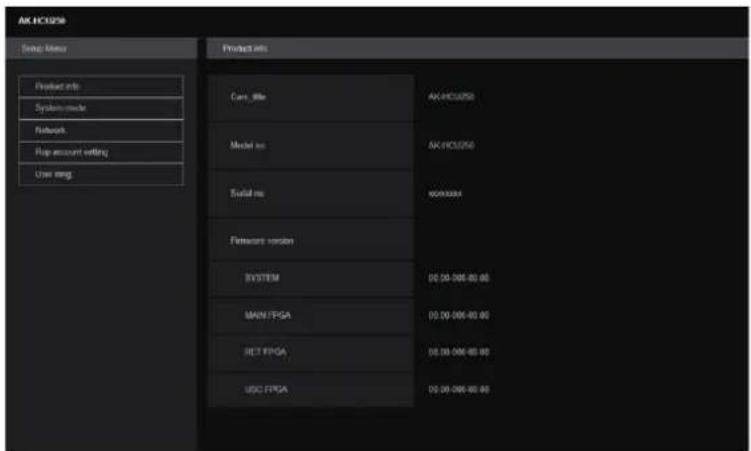
Logging into the web screen
When the web screen is displayed, you need to enter the account information.

NOTE
- The account input screen appears as a pop-up window in the web browser.
- Correctly enter the user name and password that were previously registered.
- It is recommended to regularly change the password.
Web setting screen
This screen enables you to make a variety of settings for this unit.
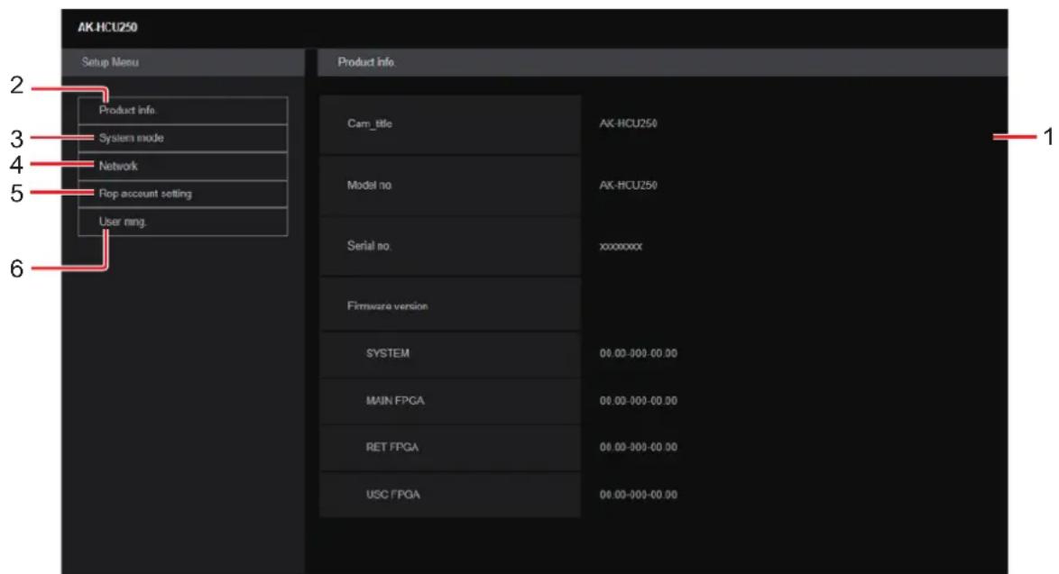
| 1 | Main area The menu screen appears. | |
| 2 | Product information button [Product info.] | Click the button to display the Product information screen [Product info.]. ➔ “Product information screen [Product info.]” (see page 62) |
| 3 | View system settings button [System mode] | Click the button to display the View system settings screen [System mode]. ➔ “View system settings screen [System mode]” (see page 63) |
| 4 | Network settings button [Network] | Click the button to display the Network settings screen [Network]. ➔ “Network settings screen [Network]” (see page 64) |
| 5 | ROP account settings button [ROP account setting] | Click the button to display the ROP account settings screen [ROP account setting]. ➔ “ROP account settings screen [ROP account setting]” (see page 78) |
| 6 | User management settings button [User mng.] | Click the button to display the User management screen [User mng.]. ➔ “User management screen [User mng.]” (see page 79) |

NOTE
- If setting values are changed from an OSD menu or another web browser while the settings menu is being displayed, there may be a mismatch between the setting values and the displayed values. If this occurs, refresh the screen displaying the settings menu in the web browser.
Product information screen [Product info.]
The versions of the unit's software can be checked on this screen.
The [Model no.], [Serial no.], [Firmware version] and other information about the unit is displayed.
| Product info. | |
| Cam_title | AK-HCU250 |
| Model no. | AK-HCU250 |
| Serial no | xxxxxxxxx |
| Firmware version | |
| SYSTEM | 00 00-000-00 00 |
| MAIN FPGA | 00.00-000-00.00 |
| RET FPGA | 00 00-000-00 00 |
| USC FPGA | 00 00-000-00 00 |
____ indicates factory default settings.
| Item Display description | |
| Cam_title | AK-HCU250Set the camera name displayed in the header of the web screen and in EasyIP Setup Tool Plus. |
| Model no. Display the unit's model number. | |
| Serial no. Displays the unit's serial number. | |
| Firmware version SYSTEM | Displays the SYSTEM version of the unit.MAIN FPGADisplays the MAIN FPGA version.RET FPGADisplays the RET FPGA version.USC FPGADisplays the USC FPGA version.• Displayed when the 4K OPTION board is fitted. |
View system settings screen [System mode]
View the system format of this unit, etc., in the View system settings screen [System mode].
The View system settings screen [System mode] consists of [Main].
Main
Click [Main] in the View system settings screen [System mode].
You can view the basic settings for the unit.
| Main | |
| Format | 2160/59.94p |
| Item Display description | |
| Format Displays the settings for the format of the signals output from the CCU. | |
Network settings screen [Network]
Make settings related to the network in the Network settings screen [Network].
The Network settings screen [Network] consists of [Network setup], [Tally in setting], [HTTPS], [NTP] and [Common].
Network setup
Click [Network setup] in the Network settings screen [Network].
Make network settings.
Confirm the settings with the [Set] button.
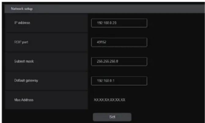
The following information is required to configure network settings. Consult your network administrator or Internet service provider.
- IP address
- Port
- Subnet mask
- Default gateway (when using a gateway server or router)
____ indicates factory default settings.
| Item Setting value | Setting details | |
| IP address | 192.168.0.20 Enter so that the address does not duplicate the IP addresses of the personal computer or other network cameras. | |
| ROP port | 49152(49152 to 49299) | Enter the port number for ROP connection. |
| Subnet mask | 255.255.255.0 Enter the subnet masks. | |
| Default gateway | 192.168.0.1 Set the default gateways. | |
| Mac address Display only display the MAC addresses. | ||
Tally in setting
Click [Tally in setting] in the Network settings screen [Network].
Make settings related to Tally control via TSL Protocol 5.0.
Confirm the settings with the [Set] button.

____ indicates factory default settings.
| Item Setting value | Setting details | |
| Index No. | 1/(1\ to\ 65534) | Enter the Index No. set by devices that output Tally. |
| Port | 62000/(60000\ to\ 65535) | Enter the Tally in port number. |
HTTPS
Click [HTTPS] in the Network settings screen [Network].
Makes settings for the HTTPS function.
The setting is confirmed with the [Set] button.
Refer to "HTTPS settings [HTTPS]" for information on how to set HTTPS.

____ indicates factory default settings.
| Item Setting value Setting details | ||
| CRT key generate | - | A CRT key (SSL encryption key) is generated by HTTPS.Generation of the CRT key is performed with the dialog displayed when you click the [Execute] button.→“Generating a CRT key (SSL encryption key) [CRT key generate]” (see page 68) |
| Self-signed Certificate - Generate | - | A self-signed security certificate is generated by HTTPS. (Self-signed Certificate)Generation of the self-signed certificate (security certificate) is performed with the dialog displayed when you click the [Execute] button.→“Generating a self-signed certificate (security certificate) [Self-signed Certificate - Generate]” (see page 69) |
| Self-signed Certificate - Information | - This displays information relating to the self-signed certificate (security certificate).When you click the [Confirm] button, the information registered in the generated self-signed certificate (security certificate) is displayed in a dialog.Click the [Delete] button to delete the generated self-signed certificate (security certificate). | |
| CA Certificate - Generate Certificate Signing Request | - When using a security certificate issued by the Certificate Authority (CA)as a security certificate for HTTPS, a Certificate Signing Request (CSR) is generated for application to the Certificate Authority (CA).Generation of the Certificate Signing Request (CSR) is performed with the dialog displayed when you click the [Execute] button.→“Generating a Certificate Signing Request (CSR) [CA Certificate - Generate Certificate Signing Request]” (see page 71) | |
| CA Certificate - CA Certificate install | - This displays information relating to server certificates (security certificates) issued by the Certificate Authority (CA), which are to be or are already installed.In the [File Open] dialog, which is displayed by clicking the [Select] button, select the file of the server certificate (security certificate) issued by the Certificate Authority (CA) and click the [Execute] button to install the server certificate (security certificate).If the server certificate (security certificate) is installed, its file name will be displayed.→“Installing a Server Certificate [CA Certificate - CA Certificate install]” (see page 72) | |
| CA Certificate - Information | - | This displays information relating to the server certificate (security certificate).When you click the [Confirm] button, the information registered in the installed server certificate (security certificate) is displayed in a dialog.If the server certificate (security certificate) is not installed, the content of the generated Certificate Signing Request (CSR) is displayed.Click the [Delete] button to delete the installed server certificate (security certificate). |
| Connection | HTTPHTTPS | This sets the method to connect to the unit. |
| HTTPS mode | TLS1.2/1.3TLS1.2TLS1.3 | This sets the encryption protocol when accessing the camera with HTTPS. |

NOTE
- To delete an enabled server certificate (security certificate), confirm that there is a backup to the said certificate in your personal computer or recording media. A server certificate (security certificate) will be needed to reinstall it.
HTTPS settings [HTTPS]
This encrypts access to the camera and sets HTTPS to improve communication safety.
Setting HTTPS is performed by following the procedures below.
The setting is confirmed with the [Set] button.

- Generating a CRT key (SSL encryption key) (page 68)
(When using self-signed certificates) (When using server certificates)
-
Generating a self-signed certificate (security certificate) (page 69)
-
Generating a Certificate Signing Request (CSR) (page 71)
Request to Certificate Authority (CA) - Generate Server Certificate
-
Installing a Server Certificate (page 72)
-
Setting the Connection Method (page 73)
Accessing the Camera by HTTPS
![PANASONIC AK-HCU250PSJ - HTTPS settings [HTTPS] - 2](/content/2026/05/910589/images/cfa3a6df45a97fbce19921b26e169ff0ab1266d8345bafe0609c089e65d39185.jpg)
NOTE
- When using a server certificate, the process from applying to the Certificate Authority (CA) to issuing a server certificate must be performed between customers and the Certificate Authority (CA).
- Use either a self-signed certificate or server certificate. When simultaneously generating a self-signed certificate and installing a server certificate, this unit will prioritize the server certificate.
■ Generating a CRT key (SSL encryption key) [CRT key generate]
![PANASONIC AK-HCU250PSJ - ■ Generating a CRT key (SSL encryption key) [CRT key generate] - 1](/content/2026/05/910589/images/d583b9efa45b814db77fc988a3cc9ccdba8342b726ff81cd094d133ff7efc18f.jpg)
NOTE
- A CRT key cannot be generated when self-signed certificates and server certificates are enabled.
- The size of the key that can be used by the Certificate Authority (CA) differs when using a server certificate. Confirm in advance the the size of the key that can be used.
- Generating a CRT key takes about 1 minute for 1024 bit and about 2 minutes for 2048 bit. Do not operate the web browser until CRT key generation is complete. Image display and communication speed may reduce while generating a CRT key.
1. Click the [Execute] button in [CRT key generate].
The [Current CRT key] dialog is displayed.

2. The size of the generated CRT key is selected from [1024bit]/[2048bit] in [CRT key generate] – [RSA key size].
![PANASONIC AK-HCU250PSJ - The size of the generated CRT key is selected from [1024bit]/[2048bit] in [CRT key generate] – [RSA key size]. - 1](/content/2026/05/910589/images/189051bb3bf8c9ff16c6b1ed9a572771de5005af0b6119101e0f627c2d825fb8.jpg)
NOTE
- When using a server certificate, the RSA key size must be in accordance with the demands of the Certificate Authority (CA) which will be applied to.
3. Click the [Execute] button.
CRT key generation starts.
When CRT key generation stops, the size of the CRT key generated by the [Current CRT key] and the date and time generation concluded will be displayed.
![PANASONIC AK-HCU250PSJ - Click the [Execute] button. - 1](/content/2026/05/910589/images/4de72a291e75a76ea086e9bf926475dde4e5ca6d138a8adaae99eeef98354b51.jpg)
NOTE
- Perform procedures 1 to 3 to change (update) the generated CRT key. Because the CRT key, self-signed certificate and server certificate are enabled as a set, it will be necessary to once again generate a self-signed certificate or apply for a server certificate when the CRT key is changed.
- When the CRT key is changed, previous CRT keys are historically managed one at a time. Clicking the [History] button in the [CRT key] of the [Current CRT key] dialog displays the [Previous CRT key] dialog, allowing confirmation of the key size and the date and time generation was completed.
Clicking the [Apply] button in [Previous CRT key] allows the previous CRT key to be switched to the current CRT key.
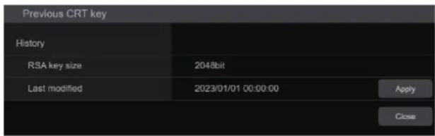
■ Generating a self-signed certificate (security certificate) [Self-signed Certificate - Generate]
![PANASONIC AK-HCU250PSJ - ■ Generating a self-signed certificate (security certificate) [Self-signed Certificate - Generate] - 1](/content/2026/05/910589/images/a0b2d820e32ccc3685440d892abf9d3eade4feda741e52c2a38f316874b25e68.jpg)
NOTE
- A self-signed certificate cannot be generated when a CRT key has not been generated.
1. Click the [Execute] button in [Self-signed Certificate] - [Generate].
[Self-signed Certificate - Generate] is displayed.

2. Input information relating to the certificate to be generated.
Items to be entered are as follows.
| Item Description | Maximum number of characters | |
| Common Name Sets a fixed camera IP address. | ||
| Country Inputs the country code. (can be abbreviated) 2 characters: country code | ||
| State Inputs the name of the state. (can be abbreviated) 128 characters | ||
| Locality Inputs the name of the city. (can be abbreviated) 128 characters | ||
| Organization Inputs the name of the organization. (can be abbreviated) 64 characters | ||
| Organizational Unit | Inputs the name of the organizational unit. (can be abbreviated) | 64 characters |
| CRT key | Displays the size of the current CRT key and the date and time generation was completed. | |

NOTE
- Characters that can be input for [Common Name], [Country], [State], [Locality], [Organization], [Organizational Unit] are 0 to 9, A to Z, a to z, and the following symbols: - . _ + ( ).
- When connecting the camera to the Internet, set the address or host name to be accessed from the Internet in [Common Name]. In this case, when accessing the camera locally, a security warning screen is displayed every time the camera is accessed even when a security certificate is installed.
- When inputting the IPv6 address in [Common Name], surround the address with [ ]. e.g. [2001:db8::10]
3. Click the [OK] button after inputting the address.
A self-signed certificate is generated.
![PANASONIC AK-HCU250PSJ - Click the [OK] button after inputting the address. - 1](/content/2026/05/910589/images/e5d4e399e7b6f8cd9fa062f3a9dcf3f0c656b61f716653b5e063dae0d5c6b318.jpg)
NOTE
- Information relating to the generated self-signed certificate is displayed in [Self-signed Certificate] - [Information]. The following is displayed depending on the status of the self-signed security certificate.
| Displayed content Description | |
| Not generated When the self-signed certificate is not generated | |
| Invalid(Reason: CA Certificate installed) | When the self-signed certificate is already generated and the server certificate is already installedThe server certificate is enabled in this case. |
| [Common Name] of self-signed certificate | When the self-signed certificate is already generated and enabled |
- When the [Confirm] button is clicked, the registered content of the generated self-signed certificate (security certificate) is displayed in the [Self-signed Certificate - Confirm] dialog.

- Click the [Delete] button to delete the generated self-signed certificate (security certificate).
- When [HTTPS] is selected in [Connection], the self-signed certificate (security certificate) cannot be deleted.
■ Generating a Certificate Signing Request (CSR) [CA Certificate - Generate Certificate Signing Request]
![PANASONIC AK-HCU250PSJ - ■ Generating a Certificate Signing Request (CSR) [CA Certificate - Generate Certificate Signing Request] - 1](/content/2026/05/910589/images/82246e84fbc83994d50285006bdf42f83f2b6c25ee1265c9aa24ecfc5d7b7b2e.jpg)
NOTE
- A certificate signing request (CSR) cannot be generated if a CRT key has not been generated.
- To generate a certificate signing request (CSR), perform the following settings in advance in the web browser Internet options.
Perform the following settings in the [Security] tab (accessed from [Tools] in the menu bar - [Internet Options] - [Security]). - Register the camera as a "Trusted Site".
- In [Level Customize], go to [File Download] from [Download] and set to [Enable].
- In [Level Customize], go to [Automatically Display Dialog when Downloading File] from [Download] and set to [Enable].
1. Click the [Execute] button in [CA Certificate - Generate Certificate Signing Request].
The [CA Certificate - Generate Certificate Signing Request] dialog is displayed.

2. Input information relating to the certificate to be generated.
Items to be entered are as follows.
| Item Description | Maximum number of characters | |
| Common Name Sets a fixed camera IP address. | ||
| Country Inputs the country code. 2 characters: country code | ||
| State Inputs the name of the state. 128 characters | ||
| Locality Inputs the name of the city. 128 characters | ||
| Organization Inputs the name of the organization. | 64 characters | |
| Organizational Unit | Inputs the name of the organizational unit. | 64 characters |
| CRT key | Displays the size of the current CRT key and the date and time generation was completed. | |

NOTE
- When using a server certificate, the information to be input must be in accordance with the demands of the Certificate Authority (CA), which will be applied to.
- Characters that can be input for [Common Name], [Country], [State], [Locality], [Organization], [Organizational Unit] are 0 to 9, A to Z, a to z, and the following symbols: - . _ + ( ).
3. Click the [OK] button after inputting the address.
The [Save As] dialog is displayed.
4. In the [Save As] dialog, assign a file name to the Certificate Signing Request (CSR) and save it in personal computer.
Apply to the Certificate Authority (CA) using the saved Certificate Signing Request (CSR).
![PANASONIC AK-HCU250PSJ - In the [Save As] dialog, assign a file name to the Certificate Signing Request (CSR) and save it in personal computer. - 1](/content/2026/05/910589/images/aad5533cde29b6e05d28df8e79f0704438fe509a0174b3a230008aae33f93991.jpg)
NOTE
- A server certificate is issued for both the generated Certificate Signing Request (CSR) and CRT key. The issued server certificate can no longer be used when generating/updating the CRT key after applying to the Certificate Authority (CA).
- The Certificate Signing Request (CSR) generated by this unit is in a PEM format.
■ Installing a Server Certificate [CA Certificate - CA Certificate install]
![PANASONIC AK-HCU250PSJ - ■ Installing a Server Certificate [CA Certificate - CA Certificate install] - 1](/content/2026/05/910589/images/1eba71065dade08f7e0d71843dca95ac0dd5c0913d655f0a101c65dee7401c66.jpg)
NOTE
- A server certificate (security certificate) cannot be installed if a Certificate Signing Request (CSR) has not been generated.
- The server certificate must have been issued by the Certificate Authority (CA) in order to install it.
1. Click the [Select] button in [CA Certificate - CA Certificate install].
The [Open File] dialog is displayed.
2. Select the server certificate file and click [Open]. Then click the [Execute] button.
The server certificate is installed.
![PANASONIC AK-HCU250PSJ - Select the server certificate file and click [Open]. Then click the [Execute] button. - 1](/content/2026/05/910589/images/d271e86e2f7efa7b97968497402cb60cbb9ec4bff512336514ebc9dafe568c99.jpg)
NOTE
- The name of the host registered to the installed server certificate is displayed in [CA Certificate] - [Information]. The following is also displayed depending on the status of the server certificate.
| Displayed content Description | |
| Invalid When the server certificate is not installed | |
| [Common Name] of server certificate | When the server certificate is already installed and enabled |
| Expired When the effective period of the server certificate has expired | |
- When the [Confirm] button is clicked, the content of the installed server certificate (security certificate) is displayed in the [CA Certificate - Confirm] dialog. (An asterisk is displayed in the [Organizational Unit] field only.)
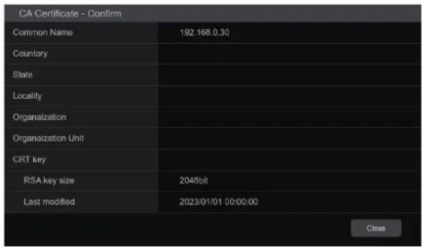
- Click the [Delete] button to delete the installed server certificate (security certificate).
- When [HTTPS] is selected in [Connection], the server certificate (security certificate) cannot be deleted.
- Perform STEP 1 to STEP 2 to update a server certificate.
- To delete an enabled server certificate (security certificate), confirm that there is a backup to the said certificate in your personal computer or recording media. A server certificate (security certificate) will be needed to reinstall it.
- The HTTPS function can no longer be used when the effective period of the server certificate has expired. In such a case, the connection method is changed to HTTP when the unit is restarted. Update the server certificate before its effective period expires.
- The effective period of the server certificate can be confirmed by double-clicking the server certificate file issued by the Certificate Authority (CA).
Setting the Connection Method [Connection]
1. Set the method to access the camera in [Connection].
HTTP: Only HTTP connection is possible.
HTTPS: Only HTTPS connection is possible.
![PANASONIC AK-HCU250PSJ - Set the method to access the camera in [Connection]. - 1](/content/2026/05/910589/images/800d9e436184fc966daa1c0984cb7942f79555788714e76cffe94691eb71137e.jpg)
NOTE
- When using an HTTPS connection, network connection with the AK-HRP1000, AK-HRP1005, AK-HRP1010, AK-HRP250, and AK-MSU1000 will be disabled.
2. Set the Port No. to be used with HTTPS in [HTTPS port].
Port No. that can be selected: 1 to 65535
The following port numbers are used by the unit so they cannot be used.
20, 21, 23, 25, 42, 53, 67, 68, 69, 80, 110, 123, 161, 162, 554, 995, 10669, 10670, 59000 to 61000
Factory settings: 443
3. Set the encryption protocol used with HTTPS in [HTTPS mode].
TLS1.2/1.3: Connection with TLS1.2/1.3 is possible.
TLS1.3: Connection with TLS1.3 is possible.
TLS1.2: Connection with TLS1.2 is possible.
4. Click the [Set] button.
The camera restarts and access to the camera via HTTPS is enabled.
![PANASONIC AK-HCU250PSJ - Click the [Set] button. - 1](/content/2026/05/910589/images/ba0f148be93b2aded2547536ed636e58b9b236e6d3ef538bfddac018d631a40f.jpg)
NOTE
- This unit will restart if the connection method is changed.
• Using a self-signed certificate
A warning screen is displayed when accessing the camera by HTTPS for the first time. Install the self-signed certificate (security certificate) in your personal computer in accordance with the screen instructions.
→ "Install the security certificate" (see page 74)
• Using a server certificate
Install the Certificate Authority (CA) root certificate or intermediate certificate in your web browser in advance. Follow the Certificate Authority (CA) procedures to acquire and install root certificates and intermediate certificates.
- When accessing the camera by HTTPS, the image display speed and frame rate of the moving image may reduce.
- When accessing the camera by HTTPS, it may take some time for the images to be displayed.
- When accessing the camera by HTTPS, images may be disturbed and sound may be interrupted.
- The maximum number of cameras that can be connected simultaneously depends on the maximum image size and distribution format.
■ Accessing the Camera by HTTPS
1. Launch the web browser in your personal computer.
2. Input the camera's IP address in the address bar of the web browser.
Input address: https://192.168.0.10/

NOTE
- When the HTTPS port No. is changed from "443", input "https://camera IP address: Port No." in the address bar. E.g. https://192.168.0.11:61443
- When this unit is in a local network, set a proxy server from the web browser (menu bar: [Tools] - [Internet Options]) to ensure that a proxy server is not used for a local address.
3. Press the [Enter] key.
The live screen [Live] is displayed.
The security certificate is installed when the security warning screen is displayed.
→ "Install the security certificate" (see page 74)
When [User auth.] is set to [On], the user name and password input screen is displayed before the live screen [Live] appears.
![PANASONIC AK-HCU250PSJ - Press the [Enter] key. - 1](/content/2026/05/910589/images/5172126fe61fbbd78ecfb27d3ac4d50038132b82ad067ed62f8534d6db3ce5c8.jpg)
NOTE
- When HTTPS is used, screen and image display may slow down and image update interval (frame rate) may also slow down.
●Install the security certificate
When using HTTPS to access the camera, the security warning screen will be displayed if the security certificate of the said camera has not been installed in your personal computer. To prevent this warning screen being displayed, the security certificate must be installed in accordance with the following procedures. If it is not installed, the security warning screen will be displayed every time the camera is accessed.

NOTE
- The security certificate will be installed to your personal computer based on the content set for [Common Name]. The content set for the "Host Name" must therefore match that set for the address/host name used to access the camera. If the content differs, a security warning screen will be displayed every time the camera is accessed.
- A security warning screen will be displayed if the camera address/host name is changed even when a security certificate has been installed. Reinstall the security certificate.
- When connecting the camera to the Internet, set the address or host name to be accessed from the Internet in [Common Name]. In this case, when accessing the camera locally, a security warning screen is displayed every time the camera is accessed even when a security certificate is installed.
- When the security certificate is correctly installed, an icon of the key will be displayed in the address bar of the web browser accessing the camera.
1. Accessing the Camera by HTTPS.
- When the security warning screen is displayed, click [Continue to this website (not recommended)].
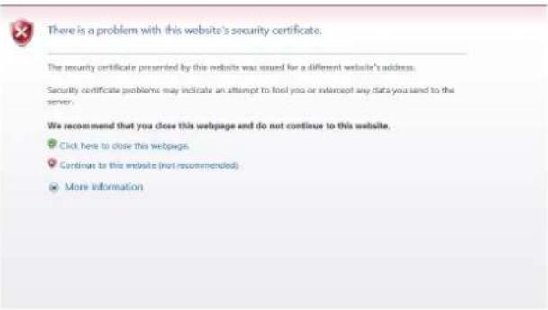
The live screen [Live] is displayed.
When the authentication screen is displayed, input the user name and password.

- When the above screen is displayed after accessing a device apart from the camera or a website, there may be a security problem, so check this carefully.
- Click [Certificate error] in the URL and then click [View certificates].

4. Click [Install Certificate...].

NOTE
- If [Install Certificate...] is not displayed, close Internet Explorer and restart it by selecting [Run as Administrator]. Right-click on [Start] - [Program] - [Internet Explorer] and click [Execute as Administrator (A).].
5. Click [Next], which is displayed in the certificate import wizard.

6. Select [Place all certificates in the following store] and click [Browse...].

7. Select [Trusted Root Certification Authorities] and click [OK].
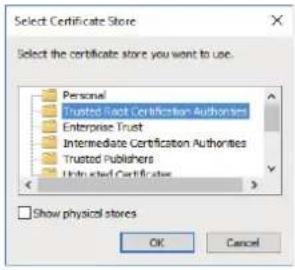
8. Click [Next].

9. Click [Finish].

10. Click [Yes].

When importing is finished, the "The import was successful." screen is displayed.
11. Click [OK].

Closing the web browser after importing the certificate and reconnecting to it will stop the "Certificate error" screen being displayed.
NTP
Click [NTP] in the Network settings screen [Network].
Make settings for the NTP function.
Confirm the settings with the [Set] button.
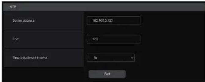
____ indicates factory default settings.
| Item Setting value | Setting details | |
| Server address | 192.168.0.123 Input the IP address of the NTP server. | |
| Port | 123 Input the port No. of the NTP server. | |
| Time adjustment interval | 1h Selects the interval (1 to 24 hours in 1-hour increments) for acquiring the time from the NTP server. | |
Common
Click [Common] in the Network settings screen [Network].
Make shared network settings.
Confirm the settings with the [Set] button.
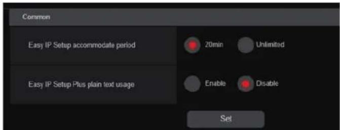
____ indicates factory default settings.
| Item Setting value | Setting details | |
| EasyIP Setup accommodate period | 20min.Unlimited | Sets the time allowed for network setting operations from EasyIP Setup Tool Plus.20min.Allows camera setting operations on the EasyIP Setup Tool Plus for just 20 minutes after start up of this unit.UnlimitedAllows camera setting operations on the EasyIP Setup Tool Plus at any time.Camera display on the EasyIP Setup Tool Plus is enabled all the time, and the camera screen can be opened.Consult the network administrator regarding the address settings for the different servers. |
| EasyIP Setup Plus plain text usage | EnableDisable | Sets whether to enable or disable encryption of communications when communicating with EasyIP Setup Tool Plus.EnableCommunications are sent and received as plain messages.DisableCommunications are sent and received as encrypted messages. |
ROP account settings screen [ROP account setting]
Make the settings for user accounts required to connect to ROPs (AK-HRP250 / AK-HRP1000 / AK-HRP1005 / AK-HRP1010 / AK-HRP1015) from this unit in the ROP account settings screen [ROP account setting]. The accounts can also be deleted here. Up to 12 users can be registered.
The ROP account settings screen [ROP account setting] consists of [User list] and [Add user].
User list
Click [User list] in the ROP account settings screen [ROP account setting].
Information about accounts already registered is displayed.
To delete a registered user account, click the [Delete] button to the right of the relevant account.

Add user
Registers a user account.
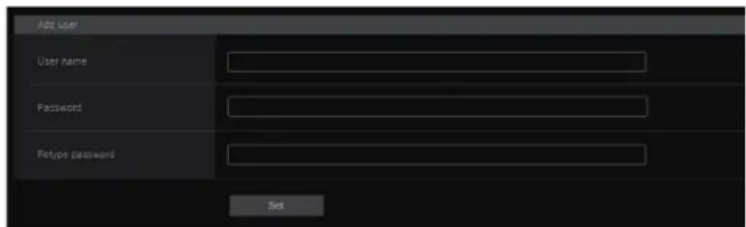
| Item Setting details | |
| User name Enter the user name. | Maximum number of characters1 to 8 half-size charactersCharacters that can be enteredHalf-size numeric characters:0123456789Half-size alphabetical characters (upper and lower cases):ABCDEFGHIJKLMNOPQRSTUVWXYZ abcdefghijklmnopqrstuvwxyzSymbols:- _ # |
| Password | Enter the password. |
| Retype password | Maximum number of characters1 to 31 half-size characters |
User management screen [User mng.]
In the User management screen [User mng.], register authentication for users that can access this unit from personal computers and mobile terminals. Up to 3 users can be registered.
The User management screen [User mng.] consists of [User list] and [Add user].
![PANASONIC AK-HCU250PSJ - User management screen [User mng.] - 1](/content/2026/05/910589/images/bdd95ae33791969ee2c4341da6914612a2fd6567e9c8c2b9ddff5916d420599a.jpg)
NOTE
- If user authentication fails more than 8 times within a 30-second period from the same IP address (personal computer), access to the unit will be disabled for a certain period.
User list
Click [User list] in the User management screen [User mng.].
Information about accounts already registered is displayed.
To delete a registered user account, click the [Delete] button to the right of the relevant account.
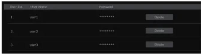

NOTE
- If there is 1 registered account, you cannot delete that account.
Add user
Registers a user account.

| Item Setting details | |
| User name Enter the user name. | Maximum number of characters1 to 32 half-size charactersCharacters that can be enteredHalf-size numeric characters:0123456789Half-size alphabetical characters (upper and lower cases):ABCDEFGHIJKLMNOPQRSTUVWXYZ abcdefghijklmnopqrstuvwxyzSymbols:! # $ % ' () * +, - . / ? @ [ ] ^ _ ~ |
| Password | Enter the password. |
| Retype password | Maximum number of characters4 to 32 half-size characters |
Troubleshooting
Operation
| Symptom Cause and | Measure |
| Cannot turn the power on. | Is the power cable connected to the outlet properly? |
| Cannot perform operation from an ROP connected with an IP connection. | Is the power on?If the [POWER] lamp of this unit is off, the power of this unit is not turned on. |
| Is a valid IP address set on the unit? | |
| Is the unit you want to operate selected correctly? | |
| Is the ROP connected correctly?Also refer to the operating instructions for the ROP. | |
| The version of the ROP may need to be upgraded to enable support for the unit.Consult your dealer. |
Reference
Connector pin assignment table
[INTERCOM] connector (page 19: 10)
HA16PRH-5S (Hirose Electric Co., Ltd.)
| Pin No. | Function Remarks | |
| 1 SHIELD | Carbon MIC: -1 dBDynamic MIC: -5 dBSelect from [DYN], [ECM], and [CBN] in the [AUDIO] menu, [CCU INTERCOM TALK] → [MIC TYPE] | |
| 2 TALK | ||
| 3 SHIELD | ||
| 4 RECEIVE | ||
| 5 NC | ||
[COMMUNICATION] connector (page 22: 2)
JBY-25S-1A3F(LF)(SN) (J.S.T. Mfg. Co., Ltd.)
| Pin No. | Function Flow of signal Remarks | ||
| 1 INCOM ENG OUT (H) CCU→SYSTEM 0 dBm, 600 Ω (4 W) / 1 V [p-p], 200 Ω (RTS) | |||
| 2 INCOM ENG OUT (C) CCU→SYSTEM | 4 W/RTS | ||
| 3 INCOM ENG (GND) | • Selected using a menu | ||
| 4 INCOM ENG IN (H) SYSTEM→CCU | |||
| 5 INCOM ENG IN (C) SYSTEM→CCU | |||
| 6 PGM IN (H) SYSTEM→CCU 0 dBm/-20 dBm, 600 Ω | • Selected using a menu | ||
| 7 PGM IN (C) SYSTEM→CCU | |||
| 8 PGM IN (GND) | |||
| 9 GND | |||
| 10 NC | |||
| 11 | R TALLY IN (H) | SYSTEM→CCU | ON:Short/TTL(H)/24 V→“Example of tally input connections” (see page 82)OFF:Open/TTL(L)/0 V |
| 12 R TALLY IN (C) | SYSTEM→CCU | ||
| 13 GND | |||
| 14 INCOM PROD OUT (H) | CCU→SYSTEM 0 dBm, 600 Ω (4 W) / 1 V [p-p], 200 Ω (RTS) | ||
| 15 INCOM PROD OUT (C) | CCU→SYSTEM | 4 W/RTS | |
| 16 INCOM PROD (GND) | • Selected using a menu | ||
| 17 INCOM PROD IN (H) | SYSTEM→CCU | ||
| 18 INCOM PROD IN (C) | SYSTEM→CCU | ||
| 19 NC | |||
| 20 NC | |||
| 21 NC | |||
| 22 NC | ON: | Short/TTL(H)/24 V→“Example of tally input connections” (see page 82)OFF:Open/TTL(L)/0 V | |
| 23 NC | |||
| 24 G TALLY IN (H) | SYSTEM→CCU | ||
| 25 G TALLY IN (C) | SYSTEM→CCU | ||
Example of tally input connections
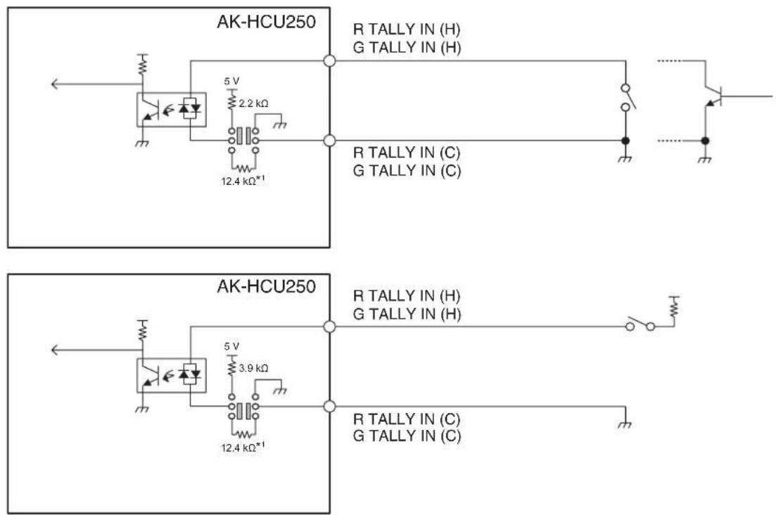
*1: Equivalent circuit
[ROP] connector (page 22: 3)
HR10G-10R-10SC (71) (Hirose Electric Co., Ltd.)
| Pin No. Function Flow of signal | ||
| 1 ROP CONT (H) | CCU→ROP | |
| 2 ROP CONT (C) | CCU→ROP | |
| 3 ROP DATA (H) | ROP→CCU | |
| 4 ROP DATA (C) | ROP→CCU | |
| 5 NC | ||
| 6 NC | ||
| 7 NC | ||
| 8 NC | ||
| 9 +16 V OUT CCU→ROP | ||
| 10 GND | ||
- Connector of cable
HR10A-10P-10P (73)
![PANASONIC AK-HCU250PSJ - [ROP] connector (page 22: 3) - 1](/content/2026/05/910589/images/197f0f17177c2b89666f57030a7270846d8d102690939a3238de3ce5705a31b8.jpg)
[MIC1] and [MIC2] connectors (page 22: 4)
HA16RV-3PG(76) (Hirose Electric Co., Ltd.)
| Pin No. Function Flow of signal Remarks | |||
| 1 SHIELD 0 dBm, 600 Ω | |||
| 2 HOT CCU→SYSTEM | |||
| 3 COLD CCU→SYSTEM | |||
- When connecting to an unbalanced input terminal of an external device, connect to it as shown in the diagram below.
XLR connector
PIN connector
(unbalanced input connector)

1 : Ground (Shield)
- Be sure to open pin 3.
2 : Hot (+Ve)
3 : Cold (-Ve)
- Some commercially available conversion connectors and conversion cables have pin 3 shorted to pin 1. Using such a conversion connector or conversion cable will cause a failure.
NG

- Do not use a conversion connector or conversion cable on which pin 3 is shorted to pin 1.
[CAMERA] connector (page 22: 5)
AK-HCU250P/AK-HCU250E: OPS2404-PR (Tajimi Electronics Co., Ltd.)
| Pin No. Function Flow of signal | |
| 1 Optical fiber CCU → CAM | |
| 2 Optical fiber CAM → CCU | |
| 3 DC 190 V (C) CCU → CAM | |
| 4 DC 190 V (H) CCU → CAM | |
| 5 Control line CCU ←→ CAM | |
| 6 Control line CCU ←→ CAM |
AK-HCU250PS/AK-HCU250ES: FXW.3K.93C.TLM (LEMO)
| Pin No. Function Flow of signal | |
| 1 Optical fiber CCU → CAM | |
| 2 Optical fiber CAM → CCU | |
| 3 Control line CCU ←→ CAM | |
| 4 Control line CCU ←→ CAM | |
| 5 DC 190 V (H) CCU → CAM | |
| 6 DC 190 V (C) CCU → CAM |
G/L specifications
| FORMAT/CCU MODE | REF-IN | ||||||||
| 1080/59i 10 | 80/23PsF 52 | 5/59i 720/59p | 1080/50i 62 | 5/50i 720/50 | p No input | ||||
| HD/HD_HDR(59.94) | |||||||||
| 1080/59.94p | √ | × × × | × × -√ | ||||||
| 1080/59.94i | √ | × × × | × × -√ | ||||||
| 1080/23.98p over 59.94i | √ | √ | √ | × × × | × - | ||||
| 1080/29.97PsF | √ | × × × | × × -√ | ||||||
| 1080/23.98PsF × | √ | √ | × × × | × - | |||||
| 720/59.94p × × | √ | √ | × × × | - | |||||
| HD/HD_HDR(50) | |||||||||
| 1080/50p × × × × | √ | √ | × - | ||||||
| 1080/25PsF | × × × | × | √ | √ | × - | ||||
| 720/50p | × × × | × × | √ | √ | - | ||||
Appearance
Unit: mm (inch)

Specifications
General
| Power supply | AK-HCU250P/AK-HCU250PS : 100 V - 120 V AC (~,), 50 Hz/60 HzAK-HCU250E/AK-HCU250ES : 100 V - 240 V AC (~,), 50 Hz/60 Hz |
| Current consumption 3 A | |
| Capacity for supplying power to a camera | DC ( →) 190 V , 0.6 A |

indicates safety information.
| Operating temperature 0 °C to 40 °C (32 °F to 104 °F) |
| Humidity 10% to 90% (no condensation) |
| Storage temperature -20 °C to 60 °C (-4 °F to 140 °F) |
| Dimensions (Width×Height×Depth) 424 mm × 88 mm × 401 mm (16-5/8 inches × 3-7/16 inches × 15-13/16 inches) (excluding protrusions) |
| Weight Approx. 7.4 k g (16.28 lb) (main unit only) |
Basic items
| System format 1920x10 | 80/59.94p/50p/29.97p/25p/23.98p |
Image input/output sections
| BNC × 33G/1.5G-SDI: 0.8 V [p-p], 75 Ω | |
| BNC × 11.5G-SDI: 0.8 V [p-p], 75 Ω | |
| BNC × 23G/1.5G-SDI: 0.8 V [p-p], 75 Ω | |
| BNC × 13G/1.5G-SDI: 0.8 V [p-p], 75 Ω | |
| BNC × 13G/1.5G-SDI: 0.8 V [p-p], 75 Ω | |
| BNC × 13G/1.5G-SDI: 0.8 V [p-p], 75 Ω | |
| BNC x 13G/1.5G-SDI: 0.8 V [p-p], 75 Ω | |
| BNC × 23-value sync/1 V VBS signal [p-p], 75 Ω3-value sync/1 V VBS signal [p-p], 75 Ω | |
| BNC × 1VBS signal: 1 V [p-p], 75 Ω | |
| BNC × 1VBS signal: 1 V [p-p], 75 Ω |
Audio output sections
| XLR x 2, 3-pin male0dBm/600 Ω |
Intercom section
| XLR x 1, 5-pin female |
Other input/output sections
| terminal | Optical fiber multi connector × 1AK-HCU250P/AK-HCU250E: Tajimi Electronics Co., Ltd., AK-HCU250PS/AK-HCU250ES: LEMO |
| terminal 10 pins | × 2 |
| terminal | 25 pins × 1 |
| terminal RJ45 × | 1 |
The symbols on this product (including the accessories) represent the following:
| ~ | AC |
| — | DC |
| | | Power on |
| ○ | Power off |

NOTE
- For details on the maximum lengths of connection cables, consult your dealer.
Inrush current, measured according to European standard EN55103-1, on initial switch-on: 3 A, after a supply interruption of 5 s: 80 A
Index
A
Accessories 11
ACCOUNT SETTING ....54
AC power socket 22
ALARM indicator 19
ANALOG PROMPT IN connector 21
ANALOG PROMPT OUT connector 21
AUDIO 47
Auto displays 35
B
BAR ID 46
C
CABLE indicators 19
CA Certificate
CA Certificate install 72
Generate Certificate Signing Request .....71
CALL button 19
CAMERA connector 22,84
CCU INTERCOM TALK 47
COMMUNICATION connector 22, 81
Connection 15,73
Cooling fan 22
CRT key generate 68
E
EasyIP Setup Tool Plus ....56
H
HD PHASE 45
HD SDI OUT connectors 21
HD SDI PROMPT IN connector 21
HD SDI PROMPT OUT connector 21
HD TRUNK OUT connector 21
HTTPS 73
I
INCOM LEVEL adjustment dial ....19
IN/OUT SELECT 44
IN/OUT SELECT(4K OPTION) 44
INTERCOM 48
INTERCOM connector 19, 81
IP connection ....15
IRIS....26
L
LAN connector 22
M
MAINTENANCE 49
Memory card access lamp 20
Memory card slot 20
Menu
Displaying 36
Operations 36
MENU button 20
Menu composition 42
MIC connector 22, 83
MIC OUT....47
MIC switch 19
N
ND NAME 50
NETWORK 51
o
OPERATION 43
Operation displays 34
OPTICAL LEVEL indicators 18
P
PGM 48
PGM LEVEL adjustment dial ....19
PGM switch 19
Picture monitor 23
PM VIEW SETTING ....52, 53
POWER switch 18
PRIV/SYSTEM selector switch 19
PROD/ENG selector switch 19
R
REF connectors 21
RET1 IN to RET2 IN connectors .....21
ROP connector 22, 82
s
SD CARD 54
Security certificate 74
SELECT dial 20
Self-signed Certificate
Generate 69
Serial connection 15
SETTING 45
Setting the user account ....16
User Account Setup Software ....16
SETUP 50
SIGNAL GND terminal 22
START UP 49
Status 28, 29, 30, 31, 32, 33
Status displays 27
Status display screen 27
SYSTEM....54
SYSTEM MODE 43
T
TALLY lamps 18
U
UPDATE 55
USER1 and USER2 buttons 20
v
VERSION 52
W
WARNING 25
Web Screen 56
MEMO
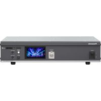
- OPERATING INSTRUCTIONS
- READ THIS FIRST
- WARNING
- CAUTION
- FOR U.S.A. AND CANADA
- NOTIFICATION (CANADA)
- FOR AK-HCU250P, AK-HCU250PS
- IMPORTANT SAFETY INSTRUCTIONS
- FCC NOTICE (USA)
- SUPPLIER'S DECLARATION OF CONFORMITY
- FCC NOTE
- FOR AK-HCU250E, AK-HCU250ES
- CAUTION FOR AC MAINS LEAD
- FOR U.K. ONLY
- EMC NOTICE FOR THE PURCHASER/USER OF THE APPARATUS
- PRE-REQUISITE CONDITIONS TO ACHIEVING COMPLIANCE WITH THE ABOVE STANDARDS
- PERFORMANCELEVEL
- MANUFACTURED BY
- IMPORTER
- AUTHORIZED REPRESENTATIVE IN EU
- IMPORTER FOR UK
- DISPOSAL OF OLD EQUIPMENT
- ONLY FOR EUROPEAN UNION AND COUNTRIES WITH RECYCLING SYSTEMS
- CONNECTION....15
- PARTS AND THEIR FUNCTIONS ....18
- PICTURE MONITOR (PM) 23
- CCU MENU 36
- TROUBLESHOOTING 80
- REFERENCE 81
- SPECIFICATIONS 87
- INDEX 89
- INTRODUCTION
- HOW TO VIEW THIS MANUAL
- ABOUT TRADEMARKS AND REGISTERED TRADEMARKS
- ABOUT COPYRIGHT
- ILLUSTRATIONS AND SCREEN DISPLAYS FEATURED IN THE MANUAL
- OVERVIEW
- NOTICE
- PERSONAL COMPUTER REQUIREMENTS
- DISCLAIMER OF WARRANTY
- NETWORK SECURITY
- MEMORY CARDS
- ACCESSORIES
- PRECAUTIONS FOR USE
- HANDLE CAREFULLY
- AVOID USING THE UNIT OUTDOORS
- TURN OFF THE POWER BEFORE CONNECTING OR DISCONNECTING CABLES
- AVOID HUMIDITY AND DUST
- CLEANING
- OPTICAL FIBER MULTI CABLE
- CONSUMABLE PARTS
- DISPOSAL OF THE UNIT
- INFORMATION ON SOFTWARE USED WITH THIS PRODUCT
- PRECAUTIONS FOR INSTALLATION
- CONNECTING A POWER SUPPLY
- GROUND OF THE POWER PLUG
- GROUNDING
- INSTALLATION LOCATION
- MOUNTING THE UNIT IN A RACK
- MOUNTING THE RACK MOUNT ADAPTERS
- REMOVE THE SETTING LEGS (A) SECURED TO THE UNIT
- MOUNT THE SUPPLIED RACK MOUNT ADAPTERS (B)
- MOUNTING POSITIONS
- NOTE
- CONNECTION
- SYSTEM CONFIGURATION
- SERIAL CONNECTION
- IP CONNECTION
- SETTING THE USER ACCOUNT
- SOFTWARE
- USE THE USER ACCOUNT SETUP SOFTWARE TO SET THE USER ACCOUNTS IN THIS UNIT
- SETTING PROCEDURE ON THIS UNIT
- EQUIPMENT CONNECTIONS
- PARTS AND THEIR FUNCTIONS
- FRONT PANEL 3
- PICTURE MONITOR (PM)
- PICTURE MONITOR DISPLAYS
- TRANSITION OF DISPLAYS
- INFORMATION DISPLAY
- WARNING DISPLAYS
- IRIS DISPLAY
- IRIS SCALE: 2STOP
- STATUS DISPLAYS
- STATUS DISPLAY SCREEN
- V-LOG INFORMATION
- STATUS DISPLAYS (PAGE 1 OF 7)
- STATUS DISPLAYS (PAGE 2 OF 7)
- STATUS DISPLAYS (PAGE 3 OF 7)
- STATUS DISPLAYS (PAGE 4 OF 7)
- STATUS DISPLAYS (PAGE 6 OF 7)
- STATUS DISPLAYS (PAGE 7 OF 7)
- OPERATION DISPLAYS
- AUTO DISPLAYS
- DISPLAYING AND HIDING THE MENUS
- PRESS THE [MENU] BUTTON
- BASIC MENU OPERATIONS
- TURN THE [SELECT] DIAL WHILE IN THE [CCU MENU], SELECT [OPERATION] OR [MAINTENANCE], AND THEN PRESS THE [SELECT] DIAL
- TURN THE [SELECT] DIAL TO MOVE THE CURSOR TO THE MENU ITEM YOU WANT TO SET, AND THEN PRESS THE [SELECT] DIAL
- TURN THE [SELECT] DIAL TO CHANGE THE VALUE, AND THEN PRESS THE [SELECT] DIAL
- OPERATION WITH MENU ITEMS THAT HAVE MULTIPLE SETTING ITEMS ON ONE LINE
- TURN THE [SELECT] DIAL TO MOVE THE CURSOR TO THE ITEM YOU WANT TO SET, AND THEN PRESS THE [SELECT] DIAL
- TEXT INPUT
- MENU COMPOSITION
- OPERATION
- SYSTEM MODE
- IN/OUT SELECT
- IN/OUT SELECT(4K OPTION)
- SETTING
- HD PHASE
- BAR ID
- AUDIO
- MIC OUT
- CCU INTERCOM TALK
- INTERCOM
- PGM
- MAINTENANCE
- START UP
- SETUP
- ND NAME
- NETWORK
- NETWORK(1/2)
- NETWORK(2/2)
- VERSION
- PM VIEW SETTING(1/2)
- PM VIEW SETTING(2/2)
- PM OPERATION STATUS
- SYSTEM
- SD CARD
- ACCOUNT SETTING
- UPDATE
- WEB SCREEN
- NETWORK SETTINGS
- EASYIP SETUP TOOL PLUS
- USING EASYIP SETUP TOOL PLUS TO SET THE UNIT'S SETTINGS
- SETTING PROCEDURE
- SELECT THE CAMERA TO CONFIGURE AND CLICK THE [NETWORK SETTINGS] BUTTON
- INPUT THE NETWORK ITEMS, AND CLICK THE [SETUP] BUTTON
- ENTER THE USER NAME AND PASSWORD REGISTERED IN THE WEB SCREEN, THEN CLICK THE [OK] BUTTON
- DISPLAYING THE WEB SCREEN
- NOTICE REGARDING THE WEB SCREEN
- IP ADDRESS AND SUBNET MASK
- PERSONAL COMPUTER ENVIRONMENT REQUIRED TO DISPLAY THE WEB SCREEN
- DISPLAYING THE WEB SCREEN USING A PERSONAL COMPUTER
- START THE WEB BROWSER OF THE PERSONAL COMPUTER
- ENTER THE IP ADDRESS YOU CONFIGURED ON THE EASYIP SETUP TOOL PLUS IN THE ADDRESS BAR OF THE WEB BROWSER
- SETS THE INITIAL ACCOUNT
- COMPLETE REGISTRATION OF THE INITIAL ACCOUNT
- DISPLAY THE SETTINGS SCREEN
- LOGGING INTO THE WEB SCREEN
- WEB SETTING SCREEN
- PRODUCT INFORMATION SCREEN [PRODUCT INFO.]
- VIEW SYSTEM SETTINGS SCREEN [SYSTEM MODE]
- MAIN
- NETWORK SETTINGS SCREEN [NETWORK]
- NETWORK SETUP
- TALLY IN SETTING
- HTTPS
- HTTPS SETTINGS [HTTPS]
- GENERATING A CRT KEY (SSL ENCRYPTION KEY) [CRT KEY GENERATE]
- CLICK THE [EXECUTE] BUTTON IN [CRT KEY GENERATE]
- THE SIZE OF THE GENERATED CRT KEY IS SELECTED FROM [1024BIT]/[2048BIT] IN [CRT KEY GENERATE] – [RSA KEY SIZE]
- CLICK THE [EXECUTE] BUTTON
- GENERATING A SELF-SIGNED CERTIFICATE (SECURITY CERTIFICATE) [SELF-SIGNED CERTIFICATE - GENERATE]
- CLICK THE [EXECUTE] BUTTON IN [SELF-SIGNED CERTIFICATE] - [GENERATE]
- INPUT INFORMATION RELATING TO THE CERTIFICATE TO BE GENERATED
- CLICK THE [OK] BUTTON AFTER INPUTTING THE ADDRESS
- GENERATING A CERTIFICATE SIGNING REQUEST (CSR) [CA CERTIFICATE - GENERATE CERTIFICATE SIGNING REQUEST]
- CLICK THE [EXECUTE] BUTTON IN [CA CERTIFICATE - GENERATE CERTIFICATE SIGNING REQUEST]
- IN THE [SAVE AS] DIALOG, ASSIGN A FILE NAME TO THE CERTIFICATE SIGNING REQUEST (CSR) AND SAVE IT IN PERSONAL COMPUTER
- INSTALLING A SERVER CERTIFICATE [CA CERTIFICATE - CA CERTIFICATE INSTALL]
- CLICK THE [SELECT] BUTTON IN [CA CERTIFICATE - CA CERTIFICATE INSTALL]
- SELECT THE SERVER CERTIFICATE FILE AND CLICK [OPEN]. THEN CLICK THE [EXECUTE] BUTTON
- SETTING THE CONNECTION METHOD [CONNECTION]
- SET THE METHOD TO ACCESS THE CAMERA IN [CONNECTION]
- SET THE PORT NO. TO BE USED WITH HTTPS IN [HTTPS PORT]
- SET THE ENCRYPTION PROTOCOL USED WITH HTTPS IN [HTTPS MODE]
- CLICK THE [SET] BUTTON
- ACCESSING THE CAMERA BY HTTPS
- LAUNCH THE WEB BROWSER IN YOUR PERSONAL COMPUTER
- INPUT THE CAMERA'S IP ADDRESS IN THE ADDRESS BAR OF THE WEB BROWSER
- PRESS THE [ENTER] KEY
- ●INSTALL THE SECURITY CERTIFICATE
- CLICK [INSTALL CERTIFICATE...]
- CLICK [NEXT], WHICH IS DISPLAYED IN THE CERTIFICATE IMPORT WIZARD
- SELECT [PLACE ALL CERTIFICATES IN THE FOLLOWING STORE] AND CLICK [BROWSE...]
- SELECT [TRUSTED ROOT CERTIFICATION AUTHORITIES] AND CLICK [OK]
- CLICK [NEXT]
- CLICK [FINISH]
- CLICK [YES]
- CLICK [OK]
- NTP
- COMMON
- ROP ACCOUNT SETTINGS SCREEN [ROP ACCOUNT SETTING]
- USER LIST
- ADD USER
- USER MANAGEMENT SCREEN [USER MNG.]
- TROUBLESHOOTING
- REFERENCE
- CONNECTOR PIN ASSIGNMENT TABLE
- [INTERCOM] CONNECTOR (PAGE 19: 10)
- [COMMUNICATION] CONNECTOR (PAGE 22: 2)
- [ROP] CONNECTOR (PAGE 22: 3)
- [MIC1] AND [MIC2] CONNECTORS (PAGE 22: 4)
- [CAMERA] CONNECTOR (PAGE 22: 5)
- APPEARANCE
- SPECIFICATIONS
- INDEX
- A
- B
- C
- E
- H
- I
- L
- M
- N
- O
- P
- R
- S
- T
- U
- V
- W
- MEMO
Brand : PANASONIC
Model : AK-HCU250PSJ
Category : Unité de contrôle caméra