
EKI-7720E-4FI-AE - Switch Advantech - Free user manual and instructions
Find the device manual for free EKI-7720E-4FI-AE Advantech in PDF.


| Product Type | Managed Industrial Ethernet Switch |
| Model | EKI-7720E-4FI-AE |
| Number of Ports | 4 x 10/100/1000Base-T(X) + 4 x 100/1000Base-X SFP |
| Dimensions (W x H x D) | 74 x 105 x 135 mm |
| Weight | 0.62 kg |
| Power Input | 12-48 VDC, dual redundant |
| Power Consumption | 12 W (max) |
| Operating Temperature | -10 to 60°C |
| Mounting | DIN-rail or wall mount |
| Switching Capacity | 12 Gbps |
| Layer 2 Functions | VLAN, QoS, STP/RSTP, IGMP snooping |
| Management | Web, CLI, SNMP v1/v2/v3 |
| Security | 802.1X, ACL, port security |
| Certifications | CE, FCC, UL |
| Cleaning and Maintenance | Wipe with a dry, soft cloth; do not use liquids or solvents |
| Repairability | No user-serviceable parts; contact Advantech support for repairs |
| Warranty | 5 years |
Frequently Asked Questions - EKI-7720E-4FI-AE Advantech
User questions about EKI-7720E-4FI-AE Advantech
0 question about this device. Answer the ones you know or ask your own.
Ask a new question about this device
Download the instructions for your Switch in PDF format for free! Find your manual EKI-7720E-4FI-AE - Advantech and take your electronic device back in hand. On this page are published all the documents necessary for the use of your device. EKI-7720E-4FI-AE by Advantech.
USER MANUAL EKI-7720E-4FI-AE Advantech
natural_image
Illustration of three network equipment units in white outline style against a solid green background (no text or symbols)EKI-7720 Series
16FE/16GE + 4G SFP Port Managed Redundant Industrial Switch
Copyright
The documentation and the software included with this product are copyrighted 2006 by Advantech Co., Ltd. All rights are reserved. Advantech Co., Ltd. reserves the right to make improvements in the products described in this manual at any time without notice. No part of this manual may be reproduced, copied, translated or transmitted in any form or by any means without the prior written permission of Advantech Co., Ltd. Information provided in this manual is intended to be accurate and reliable. However, Advantech Co., Ltd. assumes no responsibility for its use, nor for any infringements of the rights of third parties, which may result from its use.
Acknowledgements
Intel and Pentium are trademarks of Intel Corporation.
Microsoft Windows and MS-DOS are registered trademarks of Microsoft Corp.
All other product names or trademarks are properties of their respective owners.
Product Warranty (5 years)
Advantech warrants to you, the original purchaser, that each of its products will be free from defects in materials and workmanship for five years from the date of purchase.
This warranty does not apply to any products which have been repaired or altered by persons other than repair personnel authorized by Advantech, or which have been subject to misuse, abuse, accident or improper installation. Advantech assumes no liability under the terms of this warranty as a consequence of such events.
Because of Advantech's high quality-control standards and rigorous testing, most of our customers never need to use our repair service. If an Advantech product is defective, it will be repaired or replaced at no charge during the warranty period. For out-of-warranty repairs, you will be billed according to the cost of replacement materials, service time and freight. Please consult your dealer for more details.
If you think you have a defective product, follow these steps:
-
Collect all the information about the problem encountered. (For example, CPU speed, Advantech products used, other hardware and software used, etc.) Note anything abnormal and list any on screen messages you get when the problem occurs.
-
Call your dealer and describe the problem. Please have your manual, product, and any helpful information readily available.
-
If your product is diagnosed as defective, obtain an RMA (return merchandise authorization) number from your dealer. This allows us to process your return more quickly.
-
Carefully pack the defective product, a fully-completed Repair and Replacement Order Card and a photocopy proof of purchase date (such as your sales receipt) in a shippable container. A product returned without proof of the purchase date is not eligible for warranty service.
-
Write the RMA number visibly on the outside of the package and ship it prepaid to your dealer.
Printed in Taiwan Edition 1
July 2021
Declaration of Conformity
CE
This product has passed the CE test for environmental specifications. Test conditions for passing included the equipment being operated within an industrial enclosure. In order to protect the product from being damaged by ESD (Electrostatic Discharge) and EMI leakage, we strongly recommend the use of CE-compliant industrial enclo - sure products.
FCC Class A
Note: This equipment has been tested and found to comply with the limits for a Class A digital device, pursuant to part 15 of the FCC Rules. These limits are designed to provide reasonable protection against harmful interference when the equipment is operated in a commercial environment. This equipment generates, uses, and can radiate radio frequency energy and, if not installed and used in accordance with the instruction manual, may cause harmful interference to radio communications. Operation of this equipment in a residential area is likely to cause harmful interference in which case the user will be required to correct the interference at his own expense.
Technical Support and Assistance
- Visit the Advantech web site at www.advantech.com/support where you can find the latest information about the product.
- Contact your distributor, sales representative, or Advantech's customer service center for technical support if you need additional assistance. Please have the following information ready before you call:
– Product name and serial number
– Description of your peripheral attachments
– Description of your software (operating system, version, application software, etc.)
– A complete description of the problem
– The exact wording of any error messages
Warnings, Cautions and Notes
Warning! Warnings indicate conditions, which if not observed, can cause personal injury!

Caution! Cautions are included to help you avoid damaging hardware or losing data. e.g.

There is a danger of a new battery exploding if it is incorrectly installed. Do not attempt to recharge, force open, or heat the battery. Replace the battery only with the same or equivalent type recommended by the manufacturer. Discard used batteries according to the manufacturer's instructions.
Note! Notes provide optional additional information.

Document Feedback
To assist us in making improvements to this manual, we would welcome comments and constructive criticism. Please send all such - in writing to: support@advantech.com
Packing List
Before setting up the system, check that the items listed below are included and in good condition. If any item does not accord with the table, please contact your dealer immediately.
■ 1 x Industrial Ethernet Switch
■ 1 x DIN-Rail mounting Bracket and Screws
■ 1 x Wall-mounting Bracket
Safety Instructions
- Read these safety instructions carefully.
- Keep this User Manual for later reference.
- Disconnect this equipment from any DC outlet before cleaning. Use a damp cloth. Do not use liquid or spray detergents for cleaning.
- For plug-in equipment, the power outlet socket must be located near the equipment and must be easily accessible.
- Keep this equipment away from humidity.
- Put this equipment on a reliable surface during installation. Dropping it or letting it fall may cause damage.
- The openings on the enclosure are for air convection. Protect the equipment from overheating. DO NOT COVER THE OPENINGS.
- Make sure the voltage of the power source is correct before connecting the equipment to the power outlet.
- Position the power cord so that people cannot step on it. Do not place anything over the power cord.
- All cautions and warnings on the equipment should be noted.
- If the equipment is not used for a long time, disconnect it from the power source to avoid damage by transient overvoltage.
- Never pour any liquid into an opening. This may cause fire or electrical shock.
- Never open the equipment. For safety reasons, the equipment should be opened only by qualified service personnel.
- If one of the following situations arises, get the equipment checked by service personnel:
- The power cord or plug is damaged.
- Liquid has penetrated into the equipment.
- The equipment has been exposed to moisture.
- The equipment does not work well, or you cannot get it to work according to the user's manual.
- The equipment has been dropped and damaged.
- The equipment has obvious signs of breakage.
- DO NOT LEAVE THIS EQUIPMENT IN AN ENVIRONMENT WHERE THE STORAGE TEMPERATURE MAY GO -40°C (-40°F) \~ 85°C (185°F). THIS COULD DAMAGE THE EQUIPMENT. THE EQUIPMENT SHOULD BE IN A CONTROLLED ENVIRONMENT.
- The sound pressure level at the operator's position according to IEC 704-1:1982 is no more than 70 dB (A).
DISCLAIMER: This set of instructions is given according to IEC 704-1. Advantech disclaims all responsibility for the accuracy of any statements contained herein.
Safety Precaution - Static Electricity
Static electricity can cause bodily harm or damage electronic devices. To avoid damage, keep static-sensitive devices in the static-protective packaging until the installation period. The following guidelines are also recommended:
■ Wear a grounded wrist or ankle strap and use gloves to prevent direct contact to the device before servicing the device. Avoid nylon gloves or work clothes, which tend to build up a charge.
■ Always disconnect the power from the device before servicing it.
Before plugging a cable into any port, discharge the voltage stored on the cable by touching the electrical contacts to the ground surface.
Contents
Chapter 1 Product Overview ......1
1.1 Specifications.... 2
1.2 Hardware Views ...... 3
1.2.1 Front View.... 3
1.2.2 Rear View 5
1.2.3 Top View....6
1.3 Dimensions 6
Chapter 2 Switch Installation ......7
2.1 Installation Guidelines....8
2.1.1 Connecting Hardware 8
2.2 Verifying Switch Operation....8
2.3 Installing the Switch 8
2.3.1 DIN Rail Mounting....8
2.3.2 Wall-Mounting.... 10
2.4 Installing and Removing SFP Modules 12
2.4.1 Installing SFP Modules 13
2.4.2 Removing SFP Modules 14
2.5 Connecting the Switch to Ethernet Ports 15
2.5.1 RJ45 Ethernet Cable Wiring 15
2.6 Connecting the Switch to Console Port.... 16
2.7 Power Supply Installation.... 17
2.7.1 Overview.... 17
2.7.2 Considerations.... 18
2.7.3 Grounding the Device 18
2.7.4 Wiring a Relay Contact 19
2.7.5 Wiring the Power Inputs.... 20
2.8 Reset Button 21
Chapter 3 Configuration Utility ......22
3.1 First Time Setup.... 23
3.1.1 Overview.... 23
3.1.2 Introduction 23
3.1.3 Administrative Interface Access.... 23
3.1.4 Using the Graphical (Web) Interface.... 24
3.1.5 Configuring the Switch for Network Access.... 24
3.1.6 Configuring the Ethernet Ports 25
3.2 Command Line Interface Configuration 26
3.2.1 Introduction to Command-Line Interface (CLI).... 26
3.2.2 Accessing the CLI.... 26
3.3 Web Browser Configuration 27
3.3.1 Preparing for Web Configuration 27
3.3.2 System Login 27
Chapter 4 Managing Switch ......28
4.1 Log In 29
4.2 Recommended Practices.... 29
4.2.1 Changing Default Password 29
4.3 Monitoring 30
4.3.1 Device Information.... 30
4.3.2 Logging Message.... 31
4.3.3 Port Monitoring.... 32
4.3.4 Link Aggregation.... 34
4.3.5 LLDP Statistics.... 34
4.3.6 IGMP Statistics 35
4.3.7 MLD Statistics.... 36
4.4 System 38
4.4.1 IP Settings.... 38
4.4.2 IPv6 Settings.... 39
4.4.3 DHCP Client Option 82.... 39
4.4.4 DHCP Auto Provision.... 41
4.4.5 Management VLAN.... 41
4.4.6 System Time.... 42
4.4.7 Network Port 43
4.5 L2 Switching.... 45
4.5.1 Port Configuration.... 45
4.5.2 Port Mirror.... 46
4.5.3 Link Aggregation.... 47
4.5.4 802.1Q VLAN....51
4.5.5 Q-in-Q 55
4.5.6 GARP 57
4.5.7 802.3az EEE.... 58
4.5.8 Multicast.... 59
4.5.9 Jumbo Frame.... 64
4.5.10 Spanning Tree 64
4.5.11 X-Ring Elite....70
4.5.12 X-Ring Pro 71
4.5.13 Loopback Detection 74
4.5.14 ERPS 75
4.6 MAC Address Table 77
4.6.1 Static MAC....77
4.6.2 MAC Aging Time....77
4.6.3 Dynamic Forwarding Table.... 78
4.7 Security 79
4.7.1 Storm Control....79
4.7.2 Port Security 80
4.7.3 Protected Ports 81
4.7.4 DoS Prevention....81
4.7.5 Applications....84
4.7.6 802.1x 86
4.7.7 IP Security....87
4.7.8 Security Login 89
4.7.9 Access Control List 91
4.7.10 IP Source Guard 94
4.7.11 DHCP Snooping....96
4.7.12 ARP Spoofing 99
4.8 QoS 100
4.8.1 General 100
4.8.2 QoS Basic Mode.... 105
4.8.3 Rate Limit.... 107
4.8.4 Bandwidth Guarantee 109
4.9 Management 111
4.9.1 LLDP.... 111
4.9.2 SNMP 115
4.9.3 Power Over Ethernet 118
4.9.4 TCP Modbus Settings.... 120
4.9.5 DHCP Server 121
4.9.6 SMTP Client.... 125
4.9.7 RMON....128
4.9.8 NTP Server.... 132
4.10 Diagnostics 133
4.10.1 Cable Diagnostics.... 133
4.10.2 Ping Test.... 133
4.10.3 IPv6 Ping Test 134
4.10.4 System Log.... 136
4.10.5 DDM.... 138
4.10.6 LED Indication 139
4.11 Tools 140
4.11.1 IXM 140
4.11.2 Backup Manager.... 140
4.11.3 Upgrade Manager.... 141
4.11.4 Dual Image 142
4.11.5 Save Configuration 143
4.11.6 User Account 143
4.11.7 N-Key.... 144
4.11.8 Reset System 144
4.11.9 Reboot Device 144
4.12 Modbus/TCP Mapping 145
4.12.1 Modbus/TCP Mapping Table.... 146
Chapter 5 Troubleshooting.... 158
5.1 Troubleshooting 159
List of Figures
Figure 1.1 Front View .... 3
Figure 1.2 System LED Panel 4
Figure 1.3 Rear View....5
Figure 1.4 Top View....6
Figure 2.1 Installing the DIN-Rail Mounting Kit....9
Figure 2.2 Correctly Installed DIN Rail Kit 9
Figure 2.3 Removing the DIN-Rail....10
Figure 2.4 Installing Wall Mount Plates 11
Figure 2.5 Securing Wall Mounting Screws....11
Figure 2.6 Wall Mount Installation 12
Figure 2.7 Removing the Dust Plug from an SFP Slot .... 13
Figure 2.8 Installing an SFP Transceiver....13
Figure 2.9 Attaching a Fiber Optic Cable to a Transceiver.... 14
Figure 2.10 Removing a Fiber Optic Cable to a Transceiver.... 14
Figure 2.11 Removing an SFP Transceiver.... 14
Figure 2.12 Ethernet Plug & Connector Pin Position....15
Figure 2.13 Serial Console Cable....16
Figure 2.14 DB 9 Pin Position....16
Figure 2.15 Pin Assignment.... 16
Figure 2.16 Power Wiring for EKI-7720 Series....17
Figure 2.17 Grounding Connection....19
Figure 2.18 Terminal Receptor: Relay Contact 19
Figure 2.19 Terminal Receptor: Power Input Contacts....20
Figure 2.20 Removing a Terminal Block....20
Figure 2.21 Installing DC Wires in a Terminal Block 21
Figure 2.22 Securing a Terminal Block to a Receptor 21
Figure 4.1 Login Screen 29
Figure 4.2 Changing a Default Password....30
Figure 4.3 Monitoring > Device Information....30
Figure 4.4 Monitoring > Logging Message 31
Figure 4.5 Monitoring > Logging Information....32
Figure 4.6 Monitoring > Logging Message 32
Figure 4.7 Monitoring > Port Monitoring > Port Statistics ...... 32
Figure 4.8 Monitoring > Port Monitoring > IF MIB Counters 33
Figure 4.9 Monitoring > Port Monitoring > Ether-Like MIB Counters.... 33
Figure 4.10 Monitoring > Port Monitoring > Ether-Like MIB Counters.... 33
Figure 4.11 Monitoring > Port Monitoring > Port Utilization....33
Figure 4.12 Monitoring > Port Monitoring > Port Error Disable....34
Figure 4.13 Monitoring > Link Aggregation....34
Figure 4.14 Monitoring > LLDP Statistics .... 35
Figure 4.15 Monitoring > LLDP Port Statistics....35
Figure 4.16 Monitoring > IGMP Statistics 36
Figure 4.17 Monitoring > MLD Statistics....37
Figure 4.18 System > IP Settings 38
Figure 4.19 System > IP Address Information....38
Figure 4.20 System > IPv6 Settings 39
Figure 4.21 System > IPv6 Information ....39
Figure 4.22 System > DHCP Client Option 82....40
Figure 4.23 System > DHCP Client Option 82 Information....41
Figure 4.24 System > DHCP Auto Provision 41
Figure 4.25 System > DHCP Auto Provision Information 41
Figure 4.26 System > Management VLAN 42
Figure 4.27 System > System Time....42
Figure 4.28 System > System Time Information....43
Figure 4.29 System > Network Port....43
Figure 4.30 L2 Switching > Port Configuration....45
Figure 4.31 L2 Switching > Port Name Settings....45
Figure 4.32 L2 Switching > Port Status 46
Figure 4.33 L2 Switching > Port Mirror 46
Figure 4.34 L2 Switching > RSPAN....47
Figure 4.35 L2 Switching > Mirror Status....47
Figure 4.36 L2 Switching > Link Aggregation > Load Balance....47
Figure 4.37 Switching > Link Aggregation > Load Balance Information.... 48
Figure 4.38 L2 Switching > Link Aggregation > LAG Management.... 48
Figure 4.39 Switching > Link Aggregation > LAG Management Information.... 49
Figure 4.40 L2 Switching > Link Aggregation > LAG Port Settings 49
Figure 4.41 Switching > Link Aggregation > LAG Port Status....50
Figure 4.42 L2 Switching > Link Aggregation > LACP Priority Settings 50
Figure 4.43 L2 Switching > Link Aggregation > LACP Port Settings.... 50
Figure 4.44 L2 Switching > Link Aggregation > LACP Port Information Settings.... 51
Figure 4.45 L2 Switching > 802.1Q VLAN > VLAN Management 52
Figure 4.46 L2 Switching > 802.1Q VLAN > VLAN Table 52
Figure 4.47 L2 Switching > 802.1Q VLAN > PVID Settings ....52
Figure 4.48 L2 Switching > 802.1Q VLAN > Port to VLAN....54
Figure 4.49 L2 Switching > 802.1Q VLAN > Port-VLAN Mapping.... 55
Figure 4.50 L2 Switching > 802.1Q VLAN > RSPAN VLAN Mapping .... 55
Figure 4.51 L2 Switching > Q-in-Q > Global Settings....56
Figure 4.52 L2 Switching > Q-in-Q > Port Settings....56
Figure 4.53 L2 Switching > QinQ Port Information 57
Figure 4.54 L2 Switching > GARP > GARP Settings....57
Figure 4.55 L2 Switching > GARP > GVRP Settings....58
Figure 4.56 L2 Switching > GARP > GMRP Settings 58
Figure 4.57 L2 Switching > 802.3az EEE 59
Figure 4.58 L2 Switching > Multicast > Multicast Filtering....59
Figure 4.59 L2 Switching > Multicast > IGMP Snooping > IGMP Settings 60
Figure 4.60 L2 Switching > Multicast > IGMP Snooping > IGMP Snooping Information...... 60
Figure 4.61 L2 Switching > Multicast > IGMP Snooping > IGMP Querier .... 60
Figure 4.62 L2 Switching > Multicast > IGMP Snooping > IGMP Querier Status.... 61
Figure 4.63 L2 Switching > Multicast > IGMP Snooping > IGMP Static Groups ...... 61
Figure 4.64 L2 Switching > Multicast > IGMP Snooping > Multicast Groups ...... 61
Figure 4.65 L2 Switching > Multicast > IGMP Snooping > Router Ports 61
Figure 4.66 L2 Switching > Multicast > MLD Snooping > MLD Settings 62
Figure 4.67 L2 Switching > Multicast > MLD Snooping > MLD Snooping Information ...... 62
Figure 4.68 L2 Switching > Multicast > MLD Snooping > MLD Snooping Table 62
Figure 4.69 L2 Switching > Multicast > MLD Snooping > MLD Querier 63
Figure 4.70 L2 Switching > Multicast > MLD Snooping > MLD Static Group 63
Figure 4.71 L2 Switching > Multicast > MLD Snooping > Multicast Groups.... 64
Figure 4.72 L2 Switching > Multicast > MLD Snooping > Router Ports....64
Figure 4.73 L2 Switching > Jumbo Frame....64
Figure 4.74 L2 Switching > Spanning Tree > STP Global Settings....65
Figure 4.75 L2 Switching > Spanning Tree > STP Information 65
Figure 4.76 L2 Switching > Spanning Tree > STP Port Settings....66
Figure 4.77 L2 Switching > Spanning Tree > STP Bridge Settings....67
Figure 4.78 L2 Switching > Spanning Tree > STP Port Advanced Settings.... 67
Figure 4.79 Switching > Spanning Tree > STP Port Status....68
Figure 4.80 L2 Switching > Spanning Tree > MST Config Identification 68
Figure 4.81 L2 Switching > Spanning Tree > MST ID Settings 69
Figure 4.82 L2 Switching > Spanning Tree > MSTI Priority Settings....69
Figure 4.83 L2 Switching > Spanning Tree > STP Bridge Status....70
Figure 4.84 L2 Switching > Spanning Tree > MSTI Port Advanced settings.... 70
Figure 4.85 L2 Switching > Spanning Tree > STP Statistics....70
Figure 4.86 L2 Switching > X-Ring Elite > X-Ring Elite Settings....71
Figure 4.87 L2 Switching > X-Ring Elite > X-Ring Elite Groups 71
Figure 4.88 L2 Switching > X-Ring Pro > X-Ring Pro Settings....72
Figure 4.89 L2 Switching > X-Ring Pro > X-Ring Pro Groups > X-Ring Pro Groups Settings..... 72
Figure 4.90 L2 Switching > X-Ring Pro > X-Ring Pro Groups > Chain Settings....72
Figure 4.91 L2 Switching > X-Ring Pro > X-Ring Pro Groups > Couple Setting .... 73
Figure 4.92 L2 Switching > X-Ring Pro > X-Ring Pro Groups > Pair Settings....73
Figure 4.93 L2 Switching > X-Ring Pro > X-Ring Pro Groups > RPair Settings.... 73
Figure 4.94 L2 Switching > Loopback Detection > Global Settings....74
Figure 4.95 L2 Switching > Loopback Detection > Loopback Detection Global Information...... 74
Figure 4.96 L2 Switching > Loopback Detection > Port Settings....75
Figure 4.97 L2 Switching > ERPS > ERPS Settings 75
Figure 4.98 L2 Switching > ERPS > ERPS Groups....76
Figure 4.99 MAC Address Table > Static MAC 77
Figure 4.100 MAC Address Table > Static MAC Status....77
Figure 4.101 MAC Address Table > MAC Aging Time 77
Figure 4.102 MAC Address Table > Dynamic Forwarding Table 78
Figure 4.103 MAC Address Table > MAC Address Information 78
Figure 4.104 Security > Storm Control > Global Settings....79
Figure 4.105 Security > Storm Control > Storm Control Global Information....79
Figure 4.106 Security > Storm Control > Port Settings....80
Figure 4.107 Security > Storm Control > Storm Control Port Information 80
Figure 4.108 Security > Port Security....81
Figure 4.109 Security > Protected Ports....81
Figure 4.110 Security > DoS Prevention > DoS Global Settings....82
Figure 4.111 Security > Storm Control > DoS Global Information....83
Figure 4.112 Security > DoS Prevention > DoS Port Settings....84
Figure 4.113 Security > Applications > TELNET 84
Figure 4.114 Security > Applications > SSH....85
Figure 4.115 Security > Applications > HTTP....85
Figure 4.116 Security > Applications > HTTPS 86
Figure 4.117 Security > 802.1x > 802.1x Global Settings .... 86
Figure 4.118 Security > 802.1x > 802.1x Information....87
Figure 4.119 Security > 802.1x > 802.1x Port Configuration....87
Figure 4.120 Security > IP Security > Global Settings....88
Figure 4.121 Security > IP Security > Entry Settings....88
Figure 4.122 Security > Security Login > Global Settings > Global Settings....89
Figure 4.123 Security > Security Login > Global Settings > RADIUS Settings....89
Figure 4.124 Security > Security Login > Global Settings > TACACS Settings....90
Figure 4.125 Security > Security Login > Global Settings > Global Information....90
Figure 4.126 Security > Security Login > Access Control Settings > Security Login Type Settings. 90
Figure 4.127 Security > Security Login > Access Control Settings > Security Login Type Settings. 91
Figure 4.128 Security > Security Login > Access Control Settings > Access Control Information ... 91
Figure 4.129 Security > Access Control List > MAC ACL > Entry Settings 92
Figure 4.130 Security > Access Control List > MAC ACL > Entry List ....93
Figure 4.131 Security > Access Control List > IP ACL > Entry Settings....93
Figure 4.132 Security > Access Control List > IP ACL > Entry List....94
Figure 4.133 Security > IP Source Guard > Global Settings 94
Figure 4.134 Security > IP Source Guard > Global Information 95
Figure 4.135 Security > IP Source Guard > Entry Settings 95
Figure 4.136 Security > IP Source Guard > Entry Information 95
Figure 4.137 Security > DHCP Snooping > Global Settings > DHCP Snooping State Settings..... 96
Figure 4.138 Security > DHCP Snooping > Global Settings > DHCP Snooping Port Settings...... 96
Figure 4.139 Security > DHCP Snooping > Global Settings > DHCP Snooping Binding Port Settings 96
Figure 4.140 Security > DHCP Snooping > Global Settings > DHCP Snooping Information ..... 97
Figure 4.141 Security > DHCP Snooping > Entry Settings > Entry Information....97
Figure 4.142 Security > DHCP Snooping > L2-Relay Settings 97
Figure 4.143 Security > DHCP Snooping > L2-Relay Port Settings ..... 97
Figure 4.144 Security > DHCP Snooping > L2-Relay VLAN Settings....98
Figure 4.145 Security > DHCP Snooping > Circuit ID Settings 98
Figure 4.146 Security > DHCP Snooping > L2 Relay Information 98
Figure 4.147 Security > ARP Spoofing 99
Figure 4.148 Security > Entry Information 99
Figure 4.149 QoS > General > QoS Properties.... 100
Figure 4.150 QoS > General > QoS Settings 100
Figure 4.151 QoS > General > QoS Status.... 101
Figure 4.152 QoS > General > QoS Scheduling 102
Figure 4.153 QoS > General > QoS Information 102
Figure 4.154 QoS > General > CoS Mapping 103
Figure 4.155 QoS > General > CoS Mapping 103
Figure 4.156 QoS > General > CoS Mapping 104
Figure 4.157 QoS > General > DSCP Mapping 104
Figure 4.158 QoS > General > IP Precedence Mapping.... 105
Figure 4.159 QoS > QoS Basic Mode > Global Settings.... 106
Figure 4.160 QoS > General > Global Settings.... 106
Figure 4.161 QoS > QoS Basic Mode > Port Settings 106
Figure 4.162 QoS > Rate Limit > Ingress Bandwidth Control.... 107
Figure 4.163 QoS > Rate Limit > Ingress Bandwidth Control.... 107
Figure 4.164 QoS > Rate Limit > Ingress Bandwidth Control.... 107
Figure 4.165 QoS > Rate Limit > Egress Bandwidth Control 108
Figure 4.166 QoS > Rate Limit > Egress Bandwidth Control 108
Figure 4.167 QoS > Rate Limit > Egress Queue.... 108
Figure 4.168 QoS > Bandwidth Guarantee > Global Settings.... 109
Figure 4.169 QoS > Bandwidth Guarantee > Global Settings.... 110
Figure 4.170 QoS > Bandwidth Guarantee > Utilization 110
Figure 4.171 Management > LLDP > LLDP System Settings .... 111
Figure 4.172 Management > LLDP > LLDP System Settings 111
Figure 4.173 Management > LLDP > LLDP Port Settings > LLDP Port Configuration.... 112
Figure 4.174 Management > LLDP > LLDP Port Settings > Optional TLVs Selection.... 112
Figure 4.175 Management > LLDP > LLDP Port Settings > VLAN Name TLV VLAN Selection.... 113
Figure 4.176 Management > LLDP > LLDP Local Device Info.... 114
Figure 4.177 Management > LLDP > LLDP Local Device Info.... 114
Figure 4.178 Management > LLDP > LLDP Remote Device Info.... 114
Figure 4.179 Management > LLDP > LLDP Overloading.... 115
Figure 4.180 Management > SNMP > SNMP Settings 115
Figure 4.181 Management > SNMP > SNMP Community 116
Figure 4.182 Management > SNMP > SNMP Community 116
Figure 4.183 Management > SNMP > SNMPv3 EngineID.... 116
Figure 4.184 Management > SNMP > SNMPv3 Settings.... 117
Figure 4.185 Management > SNMP > SNMP Trap 118
Figure 4.186 Management > Power Over Ethernet > PoE System Settings.... 118
Figure 4.187 Management > Power Over Ethernet > PoE System Settings.... 119
Figure 4.188 Management > Power Over Ethernet > PoE Port Settings 119
Figure 4.189 Management > Power Over Ethernet > PoE Port Config Information.... 120
Figure 4.190 Management > TCP Modbus Settings > TCP Modbus Settings .... 120
Figure 4.191 Management > TCP Modbus Settings > TCP Modbus Settings .... 121
Figure 4.192 Management > DHCP Server > Status Settings 121
Figure 4.193 Management > DHCP Server > Global Settings.... 122
Figure 4.194 Management > DHCP Server > Global Settings.... 122
Figure 4.195 Management > DHCP Server > Port Settings.... 123
Figure 4.196 Management > DHCP Server > Option 82 Settings.... 123
Figure 4.197 Management > DHCP Server > Option 82 Settings.... 124
Figure 4.198 Management > DHCP Server > Client MAC Settings 125
Figure 4.199 Management > DHCP Server > Lease Entry 125
Figure 4.200 Management > SMTP Client > Global Settings.... 126
Figure 4.201 Management > SMTP Client > Profile Settings > Profile Settings.... 126
Figure 4.202 Management > SMTP Client > Profile Settings > Profile Target Mail Settings..... 127
Figure 4.203 Management > DHCP Server > Lease Entry 127
Figure 4.204 Management > SMTP Client > Sending Message 127
Figure 4.205 Management > RMON > Rmon Statistics 128
Figure 4.206 Management > RMON > RMON History 129
Figure 4.207 Management > RMON > Rmon Alarm 130
Figure 4.208 Management > RMON > RMON Event....131
Figure 4.209 Management > NTP Server....132
Figure 4.210 Diagnostics > Cable Diagnostics.... 133
Figure 4.211 Diagnostics > Ping Test.... 133
Figure 4.212 Diagnostics > IPv6 Ping Test.... 135
Figure 4.213 Diagnostics > System Log > Logging Service.... 136
Figure 4.214 Diagnostics > System Log > Local Logging 136
Figure 4.215 Diagnostics > System Log > System Log Server 137
Figure 4.216 Diagnostics > DDM > Diagnostic Alarm Settings .... 138
Figure 4.217 Diagnostics > DDM > DMI INFO .... 138
Figure 4.218 Diagnostics > LED Indication....139
Figure 4.219 Diagnostics > LED Indication....139
Figure 4.220 Tools > IXM 140
Figure 4.221 Tools > Backup Manager....141
Figure 4.222 Tools > Upgrade Manager....142
Figure 4.223 Tools > Dual Image 142
Figure 4.224 Tools > User Account 143
Figure 4.225 Tools > User Account 143
Figure 4.226 Tools > User Account....144
Figure 4.227 Tools > N-Key....144
Figure 4.228 Tools > N-Key Information....144
Chapter 1
Product Overview
1.1 Specifications
Specifications Description
| Interface I/O Port 16 x Ethernet ports + 4 x SFP ports | ||
| Power Connector 6-pin removable screw terminal (power & relay) | ||
| Physical Enclosure Metal Shell | ||
| Protection Class IP30 | ||
| Installation DIN-rail, wall mount | ||
| Dimensions (W x H x D) | 74 x 152 x 105mm (2.91" x 5.98" x 4.13") | |
| LED Display System LED SYS, R.M, PWR1, PWR2, Alarm | ||
| Port LED Speed, Link, Activity | ||
| Environment Operating Temperature | EKI-7720E-4F/EKI-7720G-4F: -10°C ~ 60°C (14°F ~ 140°F) EKI-7720E-4FI/EKI-7720G-4FI: -40°C ~ 75°C (-40°F ~ 167°F) | |
| Storage Temperature | -40°C ~ 85°C (-40°F ~ 185°F) | |
| Ambient Relative Humidity | 10 ~ 95% (non-condensing) | |
| Switch Properties | MAC Address | 8K-entry |
| Switching Bandwidth | ■ EKI-7720E: 11.2G ■ EKI-7720G: 40G | |
| Power | Power Consumption | 15W @ 48V |
| Power Input | 12~48 VDC, redundant dual power input | |
| Certifications | Safety | ■ UL 61010-2-201 ■ IEC 60950 (Compliant) |
| EMC | ■ EN 61000-4-2 ■ EN 61000-4-3 ■ EN 61000-4-4 ■ EN 61000-4-5 ■ EN 61000-4-6 ■ EN 61000-4-8 ■ EN 50121-4 | |
| EMI | CE, FCC Class A | |
| Shock | IEC 60068-2-27 | |
| Freefall | IEC 60068-2-32 | |
| Vibration | IEC 60068-2-6 | |
| Traffic Control | NEMA TS2 | |
1.2 Hardware Views
1.2.1 Front View
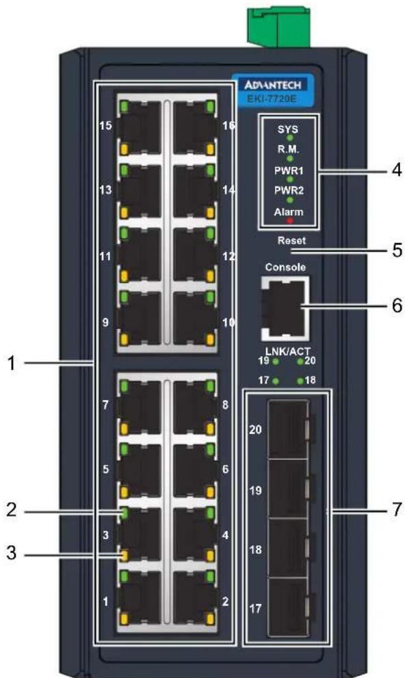
Figure 1.1 Front View
No. Item Description
| 1 ETH port RJ45 ports x 16 | |
| 2 LNK/ACT LED Link activity LED | |
| 3 Speed LED | ■ Amber: 100M■ Green: 1G |
| 4 System LED panel See “System LED Panel” on page 4 for further details. | |
| 5 Reset button Button allows for system soft reset or factory default reset. | |
| 6 Console serial port Console cable port to COM port (DB9 male) on computer to RS232 managed switch (RJ45). | |
| 7 ETH port Fiber ports x 4 | |
1.2.1.1 System LED Panel
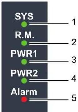
Figure 1.2 System LED Panel
No. LED Name LED Color Description
| 1 SYS Solid green System is operating normally | |
| Off System is powered down / system crash / operation initiating | |
| 2 R.M. Solid green Active when determining ring master | |
| 3 PWR1 Solid green Powered up | |
| Off Powered down or not installed | |
| 4 PWR2 Solid green Powered up | |
| Off Power down or not installed | |
| 5 Alarm Solid red Defined major policies are detected | |
| Blinking Red Defined minor policies are detected | |
| Off Powered off or system is operating normally | |
1.2.2 Rear View
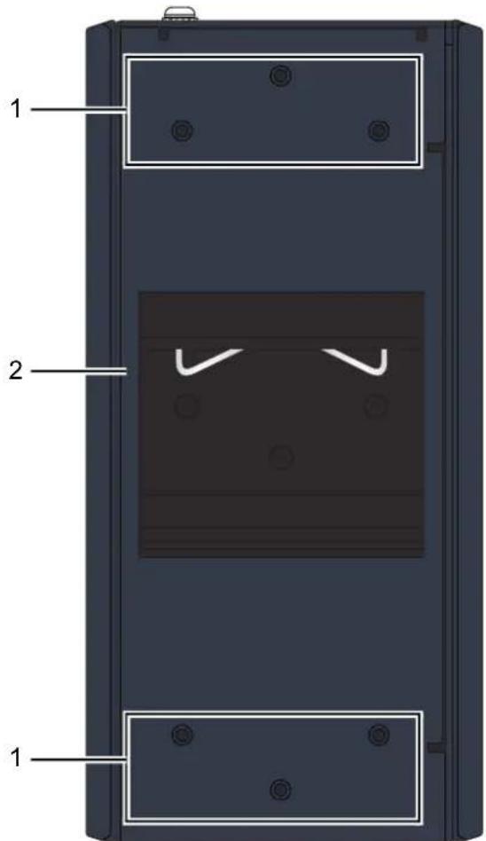
Figure 1.3 Rear View
No. Item Description
| 1 Wall mounting holes Screw holes (x6) used in the installation of a wall mounting plate | |
| 2 DIN-Rail mounting plate | Mounting plate used for the installation to a standard DIN rail |
1.2.3 Top View
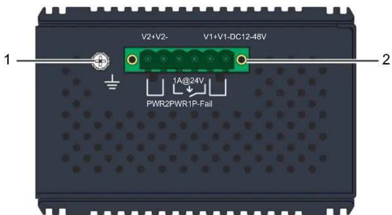
Figure 1.4 Top View
No. Item Description
1 Ground terminal Screw terminal used to ground chassis
2 Terminal block Connect cabling for power and alarm wiring
1.3 Dimensions
![56 [2.222] 45 [1.781] 56 [2.209] 15 [0.591] 38 36 [1.481] [1.400] 84 [3.287] 74 [2.913] 10 [0.390] 114 [4.488] 105 [4.134] 35 41 [1.381][1.600] 74 [2.913] 37 [1.457] 35 [1.378] 20 [0.768] 152 [5.984] 152 [5.984] 152 [5.984] 55 [2.165] 47 [1.850] 130 [5.118]11 [0.433] 110 [4.331]21 [0.827] 162 [6.374] 105 [4.134] 6-M3xP0.5 152 [5.984]](/content/2026/05/910381/images/d3ef4a6a393ae41748f27eceeeb9bb5eaae9dc6024b0ffc6a27b51a68f6531fb.jpg)
Figure 1.5 Dimensions
Chapter 2
Switch Installation
2.1 Installation Guidelines
The following guidelines are provided to optimize the device performance. Review the guidelines before installing the device.
■ Make sure cabling is away from sources of electrical noise. Radios, power lines, and fluorescent lighting fixtures can interference with the device performance.
■ Make sure the cabling is positioned away from equipment that can damage the cables.
- Operating environment is within the ranges listed range, see “Specifications” on page 2.
■ Relative humidity around the switch does not exceed 95 percent (noncondensing).
- Altitude at the installation site is not higher than 10,000 feet.
In 10/100 and 10/100/1000 fixed port devices, the cable length from the switch to connected devices can not exceed 100 meters (328 feet).
■ Make sure airflow around the switch and respective vents is unrestricted. Without proper airflow the switch can overheat. To prevent performance degradation and damage to the switch, make sure there is clarity at the top and bottom and around the exhaust vents.
2.1.1 Connecting Hardware
In this instruction, it will explain how to find a proper location for your Modbus Gateways, and how to connect to the network, hock up the power cable, and connect to the EKI-7720 Series.
2.2 Verifying Switch Operation
Before installing the device in a rack or on a wall, power on the switch to verify that the switch passes the power-on self-test (POST). To connect the cabling to the power source see “Power Supply Installation” on page 17.
At startup (POST), the System LED blinks green, while the remaining LEDs are a solidy green. Once the switch passes POST self-test, the System LED turns green. The other LEDs turn off and return to their operating status. If the switch fails POST, the System LED switches to an amber state.
After a successful self-test, power down the switch and disconnect the power cabling. The switch is now ready for installation on its final location.
2.3 Installing the Switch
2.3.1 DIN Rail Mounting
The DIN rail mount option is the quickest installation option. Additionally, it optimizes the use of rail space.
The metal DIN rail kit is secured to the rear of the switch. The device can be mounted onto a standard 35 mm (1.37") x 75 mm (3") height DIN rail. The devices can be mounted vertically or horizontally. Refer to the following guidelines for further information.
Note! A corrosion-free mounting rail is advisable.

When installing, make sure to allow for enough space to properly install the cabling.
2.3.1.1 Installing the DIN-Rail Mounting Kit
- Position the rear panel of the switch directly in front of the DIN rail, making sure that the top of the DIN rail clip hooks over the top of the DIN rail, as shown in the following illustration.
Warning! Do not install the DIN rail under or in front of the spring mechanism on the DIN rail clip to prevent damage to the DIN rail clip or the DIN rail.

Make sure the DIN rail is inserted behind the spring mechanism.
- Once the DIN rail is seated correctly in the DIN rail clip, press the front of the switch to rotate the switch down and into the release tab on the DIN rail clip. If seated correctly, the bottom of the DIN rail should be fully inserted in the release tab.
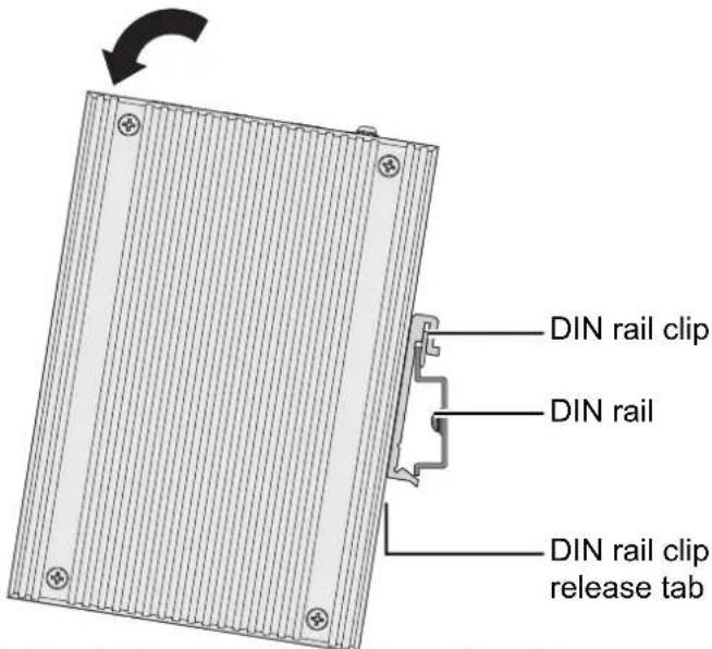
Figure 2.1 Installing the DIN-Rail Mounting Kit
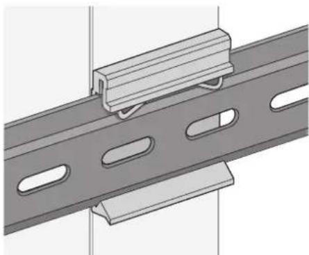
See the following figure for an illustration of a completed DIN installation procedure.
natural_image
Technical illustration of a mechanical assembly with a rail and support bracket (no text or symbols)Figure 2.2 Correctly Installed DIN Rail Kit
- Grasp the bottom of the switch and slightly rotate it upwards. If there is resistance, the switch is correctly installed. Otherwise, re-attempt the installation process from the beginning.
2.3.1.2 Removing the DIN-Rail Mounting Kit
- Ensure that power is removed from the switch, and disconnect all cables and connectors from the front panel of the switch.
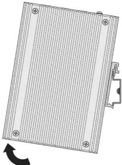
- Push down on the top of the DIN rail clip release tab with your finger. As the clip releases, lift the bottom of the switch, as shown in the following illustration.
natural_image
Technical diagram of a rectangular panel with vertical grooves and mounting holes, showing a curved arrow indicating rotation (no text or symbols present)Figure 2.3 Removing the DIN-Rail
2.3.2 Wall-Mounting
The wall mounting option provides better shock and vibration resistance than the DIN rail vertical mount.
Note! When installing, make sure to allow for enough space to properly install the cabling.

Before the device can be mounted on a wall, you will need to remove the DIN rail plate.
- Rotate the device to the rear side and locate the DIN mounting plate.
- Remove the screws securing the DIN mounting plate to the rear panel of the switch.
- Remove the DIN mounting plate. Store the DIN mounting plate and provided screws for later use.
-
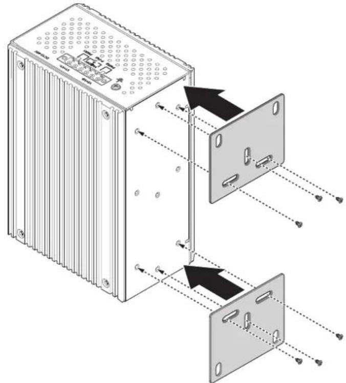
Align the wall mounting plates on the rear side. The screw holes on the device and the mounting plates must be aligned, see the following illustration.
-
Secure the wall mount plates with M3 screws, see the following figure.
natural_image
Diagram of an electronic device showing internal components and wiring connections (no text or symbols)Figure 2.4 Installing Wall Mount Plates
Once the wall mounting plates are secure on the device, you will need to attach the wall screws (x6).
-
Locate the installation site and place the switch against the wall, making sure it is the final installation location.
-
Use the wall mount plates as a guide to mark the locations of the screw holes.
-
Drill four holes over the four marked locations on the wall, keeping in mind that the holes must accommodate wall sinks in addition to the screws.
-
Insert the wall sinks into the walls.
-
Insert the screws into the wall sinks. Leave a 2 mm gap between the wall and the screw head to allow for wall mount plate insertion.
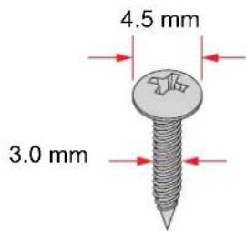
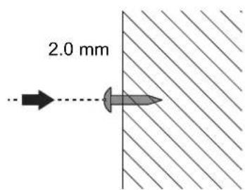
Figure 2.5 Securing Wall Mounting Screws
Note! ■ Make sure the screws dimensions are suitable for use with the wall mounting plate.
Do not completely tighten the screws into the wall. A final adjustment may be needed before fully securing the wall mounting plates on the wall.

-
Align the wall mount plate over the screws on the wall.
-
Install the wall mount plate on the screws and slide it forward to lock in place, see the following figure.
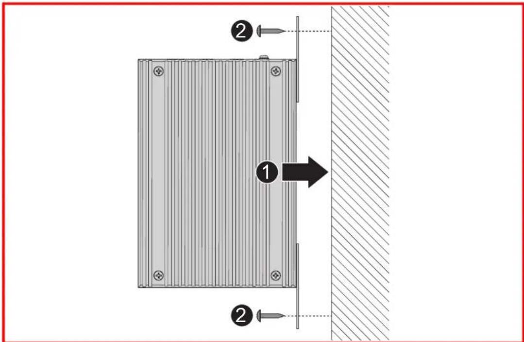
Figure 2.6 Wall Mount Installation
- Once the device is installed on the wall, tighten the screws to secure the device.
2.4 Installing and Removing SFP Modules
Up to two fiber optic ports are available (dependent on model) for use in the switch. Refer to the technical specifications for details.
The Gigabit Ethernet ports on the switch are 100/1000Base SFP Fiber ports, which require using the 100M or 1G mini-GBIC fiber transceivers to work properly. Advant-tech provides completed transceiver models for different distance requirement.
The concept behind the LC port and cable is quite straight forward. Suppose that you are connecting devices I and II; contrary to electrical signals, optical signals do not require a circuit in order to transmit data. Consequently, one of the optical lines is used to transmit data from device I to device II, and the other optical line is used transmit data from device II to device I, for full-duplex transmission.
Remember to connect the Tx (transmit) port of device I to the Rx (receive) port of device II, and the Rx (receive) port of device I to the Tx (transmit) port of device II. If you make your own cable, we suggest labeling the two sides of the same line with the same letter (A-to-A and B-to-B, as shown below, or A1-to-A2 and B1-to-B2).
Note! This is a Class 1 Laser/LED product. To avoid causing serious damage to your eyes, do not stare directly into the Laser Beam.

2.4.1 Installing SFP Modules
To connect the fiber transceiver and LC cable, use the following guidelines:
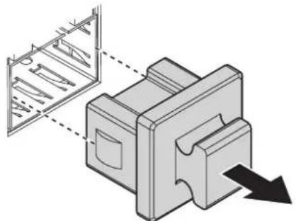
- Remove the dust plug from the fiber optic slot chosen for the SFP transceiver.
natural_image
Technical illustration of a mechanical component with internal structure and directional arrow (no text or symbols)Figure 2.7 Removing the Dust Plug from an SFP Slot
Note! Do not remove the dust plug from the SFP slot if you are not installing the transceiver at this time. The dust plug protects hardware from dust contamination.
-
Position the SFP transceiver with the handle on top, see the following figure.
-
Locate the triangular marking in the slot and align it with the bottom of the transceiver.
-
Insert the SFP transceiver into the slot until it clicks into place.
-
Make sure the module is seated correctly before sliding the module into the slot. A click sounds when it is locked in place.
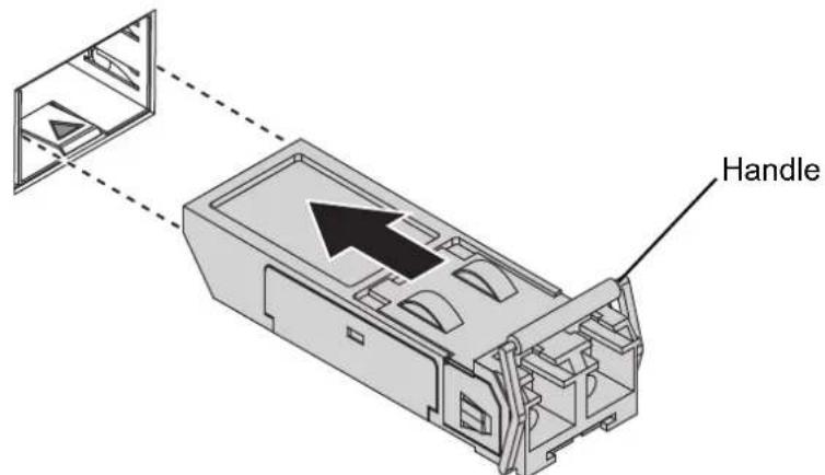
Figure 2.8 Installing an SFP Transceiver
Note! If you are attaching fiber optic cables to the transceiver, continue with the following step. Otherwise, repeat the previous steps to install the remaining SFP transceivers in the device.
- Remove the protective plug from the SFP transceiver.
Note! Do not remove the dust plug from the transceiver if you are not installing the fiber optic cable at this time. The dust plug protects hardware from dust contamination.
- Insert the fiber cable into the transceiver. The connector snaps into place and locks.
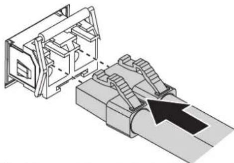
natural_image
Technical illustration of a mechanical assembly with stairs and components, no visible text or symbolsFigure 2.9 Attaching a Fiber Optic Cable to a Transceiver
- Repeat the previous procedures to install any additional SFP transceivers in the switch.
The fiber port is now setup.
2.4.2 Removing SFP Modules
To disconnect an LC connector, use the following guidelines:
- Press down and hold the locking clips on the upper side of the optic cable.
- Pull the optic cable out to release it from the transceiver.
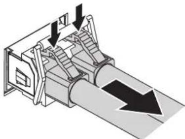
natural_image
Isometric technical diagram of a mechanical device with directional arrows indicating motion or flow (no text or symbols present)Figure 2.10 Removing a Fiber Optic Cable to a Transceiver
- Hold the handle on the transceiver and pull the transceiver out of the slot.
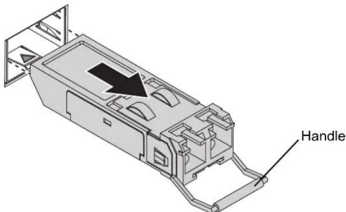
Figure 2.11 Removing an SFP Transceiver
Note! Replace the dust plug on the slot if you are not installing a transceiver.
The dust plug protects hardware from dust contamination.

2.5 Connecting the Switch to Ethernet Ports
2.5.1 RJ45 Ethernet Cable Wiring
For RJ45 connectors, data-quality, twisted pair cabling (rated CAT5 or better) is recommended. The connector bodies on the RJ45 Ethernet ports are metallic and connected to the GND terminal. For best performance, use shielded cabling. Shielded cabling may be used to provide further protection.
| Straight-thru Cable Wiring Cross-over Cable Wiring |
| Pin 1 Pin 1 Pin 1 Pin 3 |
| Pin 2 Pin 2 Pin 2 Pin 6 |
| Pin 3 Pin 3 Pin 3 Pin 1 |
| Pin 6 Pin 6 Pin 6 Pin 2 |
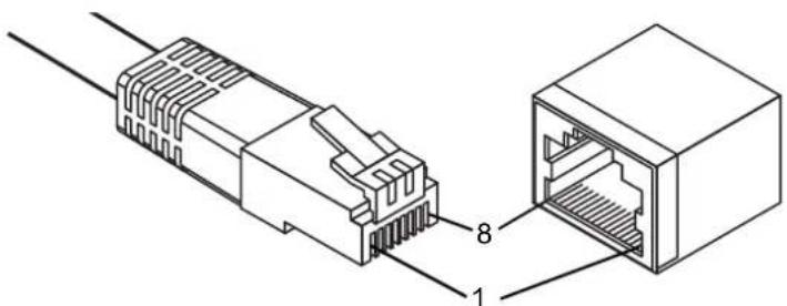
Figure 2.12 Ethernet Plug & Connector Pin Position
Maximum cable length: 100 meters (328 ft.) for 10/100BaseT.
2.6 Connecting the Switch to Console Port
The industrial switch supports a secondary means of management. By connecting the RJ45 to RS232 serial cable between a COM port on your PC (9-pin D-sub female) and the switch's RJ45 (RJ45) port, a wired connection for management can be established.

Figure 2.13 Serial Console Cable
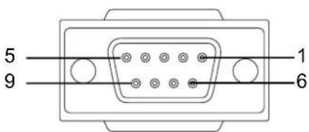
Figure 2.14 DB 9 Pin Position
DB9 Connector RJ45 Connector
| NC 1 Orange/White |
| NC 2 Orange |
| 2 3 Green/White |
| NC 4 Blue |
| 5 5 Blue/White |
| 3 6 Green |
| NC 7 Brown/White |
| NC 8 Brown |
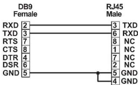
Figure 2.15 Pin Assignment
2.7 Power Supply Installation
2.7.1 Overview
Warning! Power down and disconnect the power cord before servicing or wiring the switch.

Caution! Do not disconnect modules or cabling unless the power is first switched off.

The device only supports the voltage outlined in the type plate. Do not use any other power components except those specifically designated for the switch device.
Caution! Disconnect the power cord before installation or cable wiring.

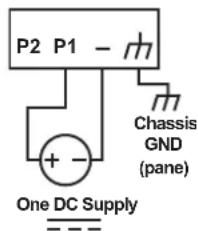
The switches can be powered by using the same DC source used to power other devices. A DC voltage range of 12 to 48 V_DC must be applied between the V1+ terminal and the V1- terminal (PW1), see the following illustrations. The chassis ground screw terminal should be tied to the panel or chassis ground. A redundant power configuration is supported through a secondary power supply unit to reduce network down time as a result of power loss.
EKI-7720 Series support 12 to 48 V _DC . Dual power inputs are supported and allow you to connect a backup power source.
Single DC Power
Redundant DC Power
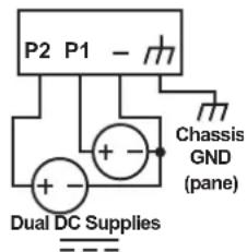
Figure 2.16 Power Wiring for EKI-7720 Series
2.7.2 Considerations
Take into consideration the following guidelines before wiring the device:
■ The Terminal Block (CN1) is suitable for 12-24 AWG (3.31 - 0.205 mm ^4 ). Torque value 7 lb-in.
The cross sectional area of the earthing conductors shall be at least 3.31 mm ^2 .
■ Calculate the maximum possible current for each power and common wire. Make sure the power draw is within limits of local electrical code regulations.
For best practices, route wiring for power and devices on separate paths.
■ Do not bundle together wiring with similar electrical characteristics.
■ Make sure to separate input and output wiring.
Label all wiring and cabling to the various devices for more effective management and servicing.
Note!
Routing communications and power wiring through the same conduit may cause signal interference. To avoid interference and signal degradation, route power and communications wires through separate conduits.
2.7.3 Grounding the Device
Caution!
Do not disconnect modules or cabling unless the power is first switched off.

The device only supports the voltage outlined in the type plate. Do not use any other power components except those specifically designated for the switch device.
Caution!
Before connecting the device properly ground the device. Lack of a proper grounding setup may result in a safety risk and could be hazardous.

Caution!
Do not service equipment or cables during periods of lightning activity.

Caution! Do not service any components unless qualified and authorized to do so.

Caution! Do not block air ventilation holes.

Electromagnetic Interference (EMI) affects the transmission performance of a device. By properly grounding the device to earth ground through a drain wire, you can setup the best possible noise immunity and emissions.
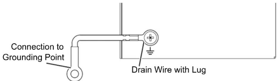
Figure 2.17 Grounding Connection
By connecting the ground terminal by drain wire to earth ground the switch and chassis can be ground.
Note! Before applying power to the grounded switch, it is advisable to use a volt meter to ensure there is no voltage difference between the power supply's negative output terminal and the grounding point on the switch.
2.7.4 Wiring a Relay Contact
The following section details the wiring of the relay output. The terminal block on the EKI-7720 Series is wired and then installed onto the terminal receptor located on the EKI-7720 Series.
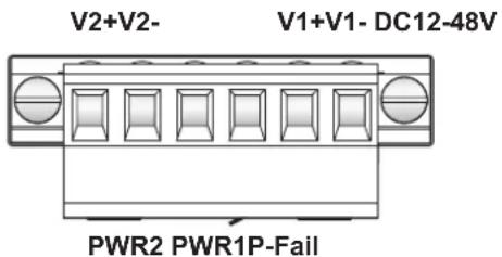
Figure 2.18 Terminal Receptor: Relay Contact
The terminal receptor includes a total of six pins: two for PWR1, two for PWR2 and two for a fault circuit.
2.7.5 Wiring the Power Inputs
Caution!
Do not disconnect modules or cabling unless the power is first switched off.

The device only supports the voltage outlined in the type plate. Do not use any other power components except those specifically designated for the switch devic
Warning!
Power down and disconnect the power cord before servicing or wiring the switch.

There are two power inputs for normal and redundant power configurations. The power input 2 is used for wiring a redundant power configuration. See the following for terminal block connector views.
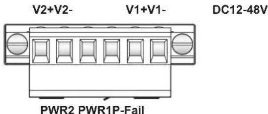
Figure 2.19 Terminal Receptor: Power Input Contacts
To wire the power inputs:
Make sure the power is not connected to the switch or the power converter before proceeding.
-
Loosen the screws securing terminal block to the terminal block receptor.
-
Remove the terminal block from the switch.
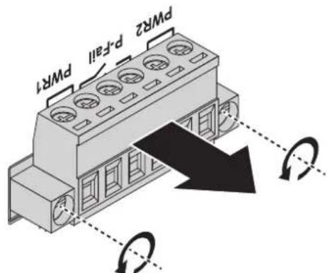
Figure 2.20 Removing a Terminal Block
-
Insert a small flat-bladed screwdriver in the V1+/V1- wire-clamp screws, and loosen the screws.
-
Insert the negative/positive DC wires into the V+/V- terminals of PW1. If setting up power redundancy, connect PW2 in the same manner.
-
Tighten the wire-clamp screws to secure the DC wires in place.
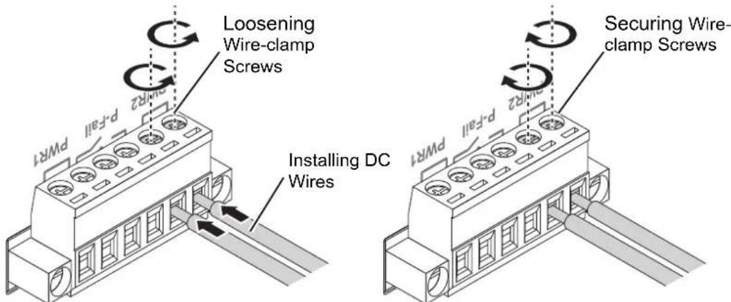
Figure 2.21 Installing DC Wires in a Terminal Block
- Align the terminal block over the terminal block receptor on the switch.
- Insert the terminal block and press it in until it is flush with the terminal block receptor.
- Tighten the screws on the terminal block to secure it to the terminal block receptor.
If there is no gap between the terminal block and the terminal receptor, the terminal block is seated correctly.
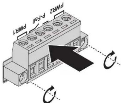
Figure 2.22 Securing a Terminal Block to a Receptor
2.8 Reset Button
Reset configuration to factory default:
Press and hold Reset button for 5 seconds.
System reboot:
Press and hold Reset button for 2 seconds.
Note! Do NOT power off the Ethernet switch when loading default settings.

Chapter 3
Configuration Utility
3.1 First Time Setup
3.1.1 Overview
The Industrial Ethernet Managed Switch is a configurable device that facilitates the interconnection of Ethernet devices on an Ethernet network. This includes computers, operator interfaces, I/O, controllers, RTUs, PLCs, other switches/hubs or any device that supports the standard IEEE 802.3 protocol.
This switch has all the capabilities of a store and forward Ethernet switch plus advanced management features such as SNMP, RSTP and port mirroring. This manual details how to configure the various management parameters in this easy to use switch.
3.1.2 Introduction
To take full advantage of all the features and resources available from the switch, it must be configured for your network.
The switch implements Rapid Spanning Tree Protocol (RSTP) and Simple Network Management Protocol (SNMP) to provide most of the services offered by the switch. Rapid Spanning Tree Protocol allows managed switches to communicate with each other to ensure that there exists only one active route between each pair of network nodes and provides automatic failover to the next available redundant route. A brief explanation of how RSTP works is given in the Spanning Tree section.
The switch is capable of communicating with other SNMP capable devices on the network to exchange management information. This statistical/derived information from the network is saved in the Management Information Base (MIB) of the switch. The MIB is divided into several different information storage groups. These groups will be elaborated in detail in the Management and SNMP information section of this document. The switch implements Internet Group Management Protocol (IGMP) to optimize the flow of multicast traffic on your network.
The switch supports both port-based and tag-based Virtual LANs for flexible integration with VLAN-aware networks with support for VLAN-unaware devices.
3.1.3 Administrative Interface Access
There are several administrative interfaces to the switch:
- A graphical web interface accessible via the switch's built-in web server. Both HTTP and secure HTTPS with SSL are supported.
Note! This is the recommended method for managing the switch.

-
A terminal interface via the RS232 port or over the network using telnet or Secure Shell (SSH).
-
An SNMP interface can be used to read/write many settings.
-
Command Line Interface (CLI) can be used to read/write most settings. Initial setup must be done using an Ethernet connection (recommended) or the serial port.
3.1.4 Using the Graphical (Web) Interface
The graphical interface is provided via a web server in the switch and can be accessed via a web browser such as Opera, Mozilla, or Internet Explorer.
Note! JavaScript must be supported and enabled in your browser for the graphical interface to work correctly.

HTTP and HTTPS (secure HTTP) are supported for access to the web server. By default, only HTTP is enabled. Either or both may be enabled or disabled to secure the switch. (See the Remote Access Security topic in this section.)
To access the graphical interface, enter a URL like HTTP://192.168.1.1 in your browser's address bar. Replace "http" with "https" to use secure http and replace "192.168.1.1" with your switch's IP address if you've changed it from the factory default.
The web server in the switch uses a signed security certificate. When you access the server via https, you may see a warning dialog indicating that the certificate was signed by an unknown authority. This is expected and to avoid this message in the future you can choose to install the certificate on your computer.
Note! This manual describes and depicts the web user interface in detail. The terminal interface is not specifically shown but is basically the same.

3.1.5 Configuring the Switch for Network Access
To control and monitor the switch via the network, it must be configured with basic network settings, including an IP address and subnet mask.
To configure the switch for network access, select [Add Menu Address Here] to reach the System Settings menu. The settings in this menu control the switch's general network configuration.
DHCP Enabled/Disabled: The switch can automatically obtain an IP address from a server using the Dynamic Host Configuration Protocol (DHCP). This can speed up initial set up, as the network administrator does not have to find an open IP address.
IP Address and subnet mask configuration: The IP address for the switch can be changed to a user-defined address along with a customized subnet mask to separate subnets.
Note! Advanced users can set the IP address to 0.0.0.0 to disable the use of an IP address for additional security. However, any features requiring an IP address (i.e., web interface, etc.) will no longer be available.
Default Gateway Selection: A Gateway Address is chosen to be the address of a router that connects two different networks. This can be an IP address or a Fully Qualified Domain Name (FQDN) such as "domainname.org".
NTP Server: The IP address or domain name of an NTP (Network Time Protocol) server from which the switch may retrieve the current time at startup. Please note that using a domain name requires that at least one domain name server be configured.
3.1.6 Configuring the Ethernet Ports
The switch comes with default port settings that should allow you to connect to the Ethernet Ports with out any necessary configuration. Should there be a need to change the name of the ports, negotiation settings or flow control settings, you can do this in the Port Configuration menu. Access this menu by selecting Setup from the Main menu, and then selecting Main Settings.
■ Port Name: Each port in the managed switch can be identified with a custom name. Specify a name for each port here.
- Admin: Ports can be enabled or disabled in the managed switch. For ports that are disabled, they are virtually non-existent (not visible in terms of switch operation or spanning tree algorithm). Choose to enable or disable a port by selecting Enabled or Disabled, respectively.
Negotiation: All copper ports and gigabit fiber ports in the managed switch are capable of autonegotiation such that the fastest bandwidth is selected. Choose to enable auto-negotiation or use fixed settings. 100Mbps Fiber ports are Fixed speed only.
Speed/Duplex/Flow Control: The managed switch accepts three local area network Ethernet Standards. The first standard, 10BASE-T, runs 10Mbps with twisted pair Ethernet cable between network interfaces. The second local area network standard is 100BASE-T, which runs at 100Mbps over the same twisted pair Ethernet cable. Lastly, there is 100BASE-F, which enables fast Ethernet (100Mbps) over fiber.
These options are available:
■ 10h–10 Mbps, Half Duplex
■ 10f –10 Mbps, Full Duplex
■ 100h–100 Mbps, Half Duplex
■ 100f –100 Mbps, Full Duplex
■ 1000f–1000 Mbps, Full Duplex
On managed switches with gigabit combination ports, those ports with have two rows, a standard row of check boxes and a row labeled "SFP" with radio buttons. The SFP setting independently sets the speed at which a transceiver will operate if one is plugged in. Otherwise, the switch will use the fixed Ethernet port and the corresponding settings for it.
Note! When 100f is selected for the SFP of a gigabit combination port, the corresponding fixed Ethernet jack will be disabled unless it is changed back to 1000F.
3.2 Command Line Interface Configuration
3.2.1 Introduction to Command-Line Interface (CLI)
The command-line interface (CLI) is constructed with an eye toward automation of CLI-based configuration. The interaction is modeled on that used in many Internet protocols such as Telnet, FTP, and SMTP. After each command is entered and processed, the switch will issue a reply that consists of a numeric status code and a human-readable explanation of the status.
The general format of commands is:
section parameter [value]
where:
– section is used to group parameters.
- parameter will specify the parameter within the section. For example, the network section will have parameters for DHCP, IP address, subnet mask, and default gateway.
- value is the new value of the parameter. If value is omitted, the current value is displayed.
Please note that new values will not take effect until explicitly committed.
Sections and parameter names are case sensitive (e.g., “Network” is not the same as “network”).
Note!
Any commands in the CLI Commands section of this chapter, with the exception of the global commands, must be prefaced with the name of the section they are in. For example, to change the IP address of the switch, you would type:
network address
3.2.2 Accessing the CLI
To access the CLI interface, establish Ethernet or serial connectivity to the switch.
To connect by Ethernet, open a command prompt window and type:
telnet
At the login prompt, type "cli" for the username and "admin" for the password. The switch will respond with "Managed switch configuration CLI ready".
3.3 Web Browser Configuration
The switch has an HTML based user interface embedded in the flash memory. The interface offers an easy to use means to manage basic and advanced switch functions. The interface allows for local or remote switch configuration anywhere on the network.
The interface is designed for use with [Internet Explorer (6.0), Chrome, Firefox].
3.3.1 Preparing for Web Configuration
The interface requires the installation and connection of the switch to the existing network. A PC also connected to the network is required to connect to the switch and access the interface through a web browser. The required networking information is provided as follows:
IP address: 192.168.1.1
■ Subnet mask: 255.255.255.0
■ Default gateway: 192.168.1.254
■ User name: admin
■ Password: admin
3.3.2 System Login
Once the switch is installed and connected, power on the switch. The following information guides you through the logging in process.
- Launch your web browser on the PC.
- In the browser's address bar, type the switch's default IP address (192.168.1.1). The login screen displays.
- Enter the user default name and password (admin / admin).
- Click OK on the login screen to log in. The main interface displays.
Chapter 4
Managing Switch
4.1 Log In
To access the login window, connect the device to the network, see "Connecting the Switch to Ethernet Ports" on page 15. Once the switch is installed and connected, power on the switch see the following procedures to log into your switch.
When the switch is first installed, the default network configuration is set to DHCP enabled. You will need to make sure your network environment supports the switch setup before connecting it to the network.
- Launch your web browser on a computer.
- In the browser's address bar type in the switch's default IP address (192.168.1.1). The login screen displays.
- Enter the default user name and password (admin/admin) to log into the management interface. You can change the default password after you have successfully logged in.
- Click Login to enter the management interface.
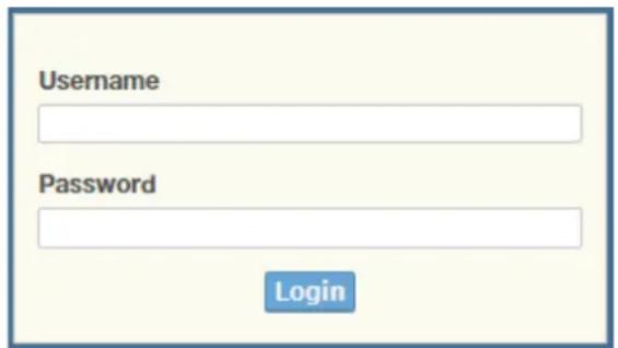
Figure 4.1 Login Screen
4.2 Recommended Practices
One of the easiest things to do to help increase the security posture of the network infrastructure is to implement a policy and standard for secure management. This practice is an easy way to maintain a healthy and secure network.
After you have performed the basic configurations on your switches, the following is a recommendation which is considered best practice policy.
4.2.1 Changing Default Password
In keeping with good management and security practices, it is recommended that you change the default password as soon as the device is functioning and setup correctly. The following details the necessary steps to change the default password.
To change the password:
- Navigate to Tools > User Account.
- From the User drop-down menu, select the Admin (default) account.
- In the User Name field, enter admin for this account. It is not necessary to change the user name, however, a change in the default settings increases the security settings.
-
In the Password field, type in the new password. Re-type the same password in the Retype Password field.
-
Click Apply to change the current account settings.
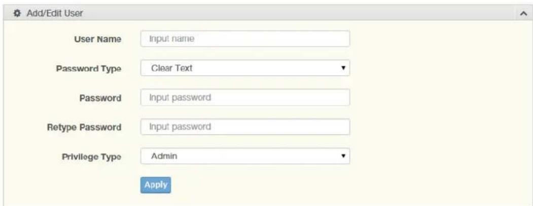
Figure 4.2 Changing a Default Password
After saving all the desired settings, perform a system save (Tools > Save Configuration). The changes are saved.
4.3 Monitoring
4.3.1 Device Information
The Device Information menu lists information, such as: System Name, System Location, MAC Address, Firmware version, and more, pertaining to the system. The information is for review only. To modify the device information, see the respective item within the user interface.
To access this page, click Monitoring > Device Information.
| Device Information | |
| Information Name | Information Value |
| System Name | Switch |
| System Location | Default |
| System Contact | Default |
| MAC Address | C4:00.AD:F2:12:C8 |
| IP Address | 192.168.1.1 |
| Subnet Mask | 255.255.255.0 |
| Gateway | 192.168.1.254 |
| Loader Version | 1.01.S05011 |
| Loader Date | Oct 22 2020 - 16:26:44 |
| Firmware Version | 1.02.01 |
| Firmware Date | Oct 22 2020 - 16:27:05 |
| Build Version | D091016S05255 |
| System OID | 1.3.6.1.4.1.10297.202.7000 |
| System Up Time | 0 days, 0 hours, 14 mins, 12 secs |
Figure 4.3 Monitoring > Device Information
The following table describes the items in the previous figure.
| Item | Description |
| System Name | ClickSwitchto enter the system name: up to 128 alphanumeric characters (default is Switch). |
| System Location | ClickDefaultto enter the location: up to 256 alphanumeric characters (default is Default). |
| System Contact Click Default to enter the contact person: up to 128 alphanumeric characters (default is Default). | |
| MAC Address Displays the MAC address of the switch. | |
| IP Address Displays the assigned IP address of the switch. | |
| Subnet Mask Displays the assigned subnet mask of the switch. | |
| Gateway Displays the assigned gateway of the switch. | |
| Loader Version Displays the current loader version of the switch. | |
| Loader Date Displays the current loader build date of the switch. | |
| Firmware Version Displays the current firmware version of the switch. | |
| Firmware Date Displays the current firmware build date of the switch. | |
| Build Version Displays the current firmware build version of the switch. | |
| System Object ID Displays the base object ID of the switch. | |
| System Up Time Displays the time since the last switch reboot. | |
4.3.2 Logging Message
The Logging Message Filter page allows you to enable the display of logging message filter.
To access this page, click Monitoring > Logging Message.
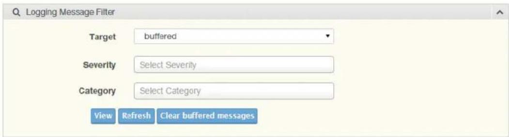
Figure 4.4 Monitoring > Logging Message
The following table describes the items in the previous figure.
| Item | Description |
| Target | Click the drop-down menu to select a target to store the log messages.■ Buffered: Store log messages in RAM. All log messages are cleared after system reboot.■ File: Store log messages in a file. |
| Severity | The setting allows you to designate a severity level for the Logging Message Filter function.Click the drop-down menu to select the severity level target setting.The level options are:■ emerg: Indicates system is unusable. It is the highest level of severity.■ alert: Indicates action must be taken immediately.■ crit: Indicates critical conditions.■ error: Indicates error conditions.■ warning: Indicates warning conditions.■ notice: Indicates normal but significant conditions.■ info: Indicates informational messages.■ debug: Indicates debug-level messages. |
| Category | Click the drop-down menu to select the category level target setting. |
Item Description
| View | Click View to display all Logging Information and Logging Message information. |
| Refresh Click Refresh to update the screen. | |
| Clear buffered messages | Click Clear buffered messages to clear the logging buffer history list. |
The ensuing table for Logging Information table settings are informational only: Target, Severity and Category.
| Information Name | Information Value |
| Target | buffered |
| Severity | emerg, alert, crit, error, warning, notice |
| Category | ACL, CABLE_DIAG, IGMP_SNOOPING, MLD_SNOOPING, L2, LLDP, Mirror, Platforms, PM, Port, QoS, Rate, SNMP, STP, LBD, GVRP, Security, System, Trunk, VLAN, QINQ, XRing, XRing3, ERPS, PoE |
Figure 4.5 Monitoring > Logging Information
The ensuing table for Logging Message table settings are informational only: No, Time Stamp, Category, Severity, and Message.
| No. | Time Stamp | Category | Severity | Message |
| 1 | Jan 01 2000 08:13:18 | System | notice | New http connection for user admin, source 192.168.1.2 ACCEPTED |
| 2 | Jan 01 2000 08:03:41 | System | notice | New http connection for user admin, source 192.168.1.2 ACCEPTED |
| 3 | Jan 01 2000 08:00:36 | System | crit | System cold start |
| 4 | Jan 01 2000 08:00:36 | System | notice | Logging is enabled |
| 5 | Jan 01 2000 08:00:36 | System | cut | power supply 1 is powered down |
Figure 4.6 Monitoring > Logging Message
4.3.3 Port Monitoring
Port Network Monitor is a bandwidth and network monitoring tool for the purpose of capturing network traffic and measuring of network throughput. The monitoring functionality includes listing of port statistics as well as port utilization.
4.3.3.1 Port Statistics
To access this page, click Monitoring > Port Monitoring > Port Statistics.
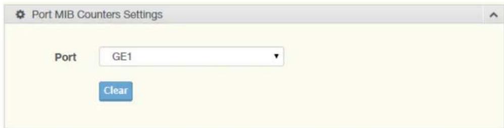
Figure 4.7 Monitoring > Port Monitoring > Port Statistics
The following table describes the items in the previous figure.
Item Description
| Port Click the drop-down menu to select a port and its captured statistical setting values. |
Clear Click Clear to clear the counter selections.
The following table provides information for IF MIB Counters settings.
| IF MIB Counter Name | MIB Counter Value |
| ifInOctets | 0 |
| ifInUcastPkts | 0 |
| ifInNUcastPkts | 0 |
| ifInDiscards | 0 |
| ifOutOctets | 0 |
| ifOutUcastPkts | 0 |
| ifOutNUcastPkts | 0 |
| ifOutDiscards | 0 |
| ifInMulticastPkts | 0 |
| ifInBroadcastPkts | 0 |
| ifOutMulticastPkts | 0 |
| ifOutBroadcastPkts | 0 |
Figure 4.8 Monitoring > Port Monitoring > IF MIB Counters
The following table provides information for Ether-Like MIB Counters settings.
| Ether-Like MIB Counter Name | MIB Counter Value |
| dot3StatsAlignmentErrors | 0 |
| dot3StatsFCSErrors | 0 |
| dot3StatsSingleCollisionFrames | 0 |
| dot3StatsMultipleCollisionFrames | 0 |
| dot3StateDeferredTransmissions | 0 |
| dot3StatsLateCollisions | 0 |
| dot3StatsExcessiveCollisions | 0 |
| dot3StatsFrameToolLongs | 0 |
| dot3StatsSymbolErrors | 0 |
| dot3ControllUnknownOpcodes | 0 |
| dot3InPauseFrames | 0 |
| dot3OutPauseFrames | 0 |
Figure 4.9 Monitoring > Port Monitoring > Ether-Like MIB Counters
The following table provides information for Rmon MIB Counters settings.

Figure 4.10 Monitoring > Port Monitoring > Ether-Like MIB Counters
4.3.3.2 Port Utilization
To access this page, click Monitoring > Port Monitoring > Port Utilization.

Figure 4.11 Monitoring > Port Monitoring > Port Utilization
The following table describes the items in the previous figure.
Item Description
Refresh period Click the drop-down menu to select and designate a period (second intervals) to refresh the information (TX and RX) listings.
IFG Click the drop-down menu to enable or disable the Interframe Gap (IFG) statistic.
4.3.3.3 Port Error Disable
The Port Error Disable page displays the error information of the switch ports. To access this page, click Monitoring > Port Monitoring > Port Error Disable
| Error Disable Reason | Timer Status | Recover Time |
| bpduguard | Disabled | 0 |
| storm-control | Disabled | 0 |
| ingress-bandwidth-control | Disabled | 0 |
| loopback-detection | Enabled | 60 |
Figure 4.12 Monitoring > Port Monitoring > Port Error Disable
The following table describes the items in the previous figure.
Item Description
bpduguard Displays the error status.
| storm-control | Displays the error status. |
| ingress-bandwidth-control | Displays the error status. |
| loopback-detection | Displays the error status. |
4.3.4 Link Aggregation
The Link Aggregation function provides LAG information for each trunk. It displays membership status, link state and membership type for each port.
To access this page, click Monitoring > Link Aggregation.
| LAG | Name | Type | Link State | Active Member | Standby Member |
| Trunk1 | - | Not Present | - | - | |
| Trunk2 | - | Not Present | - | - | |
| Trunk3 | - | Not Present | - | - | |
| Trunk4 | - | Not Present | - | - | |
| Trunk5 | - | Not Present | - | - | |
| Trunk6 | - | Not Present | - | - | |
| Trunk7 | - | Not Present | - | - | |
| Trunk8 | - | Not Present | - | - |
Figure 4.13 Monitoring > Link Aggregation
4.3.5 LLDP Statistics
The LLDP Statistics page displays the LLDP statistics.
To access this page, click Monitoring > LLDP Statistics.
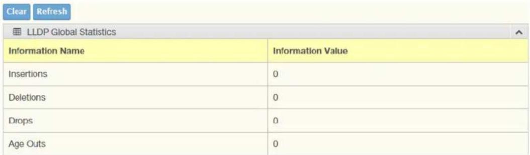
Figure 4.14 Monitoring > LLDP Statistics
The following table describes the items in the previous figure.
Item Description
Clear Click Clear to reset LLDP Statistics of all the interfaces.
Refresh Click Refresh to update the data on the screen with the present state of the data in the switch.
The following figure displays the LLDP Port Statistics settings.
| Port | TX Frames | RX Frames | RX TLVs | RX Ageouts | |||
| Total | Total | Discarded | Errors | Discarded | Unrecognized | Total | |
| GE1 | 0 | 0 | 0 | 0 | 0 | 0 | 0 |
| GE2 | 0 | 0 | 0 | 0 | 0 | 0 | 0 |
| GE3 | 0 | 0 | 0 | 0 | 0 | 0 | 0 |
| GE4 | 0 | 0 | 0 | 0 | 0 | 0 | 0 |
| GE5 | 0 | 0 | 0 | 0 | 0 | 0 | 0 |
| GE6 | 0 | 0 | 0 | 0 | 0 | 0 | 0 |
| GE7 | 0 | 0 | 0 | 0 | 0 | 0 | 0 |
| GE8 | 0 | 0 | 0 | 0 | 0 | 0 | 0 |
| GE9 | 0 | 0 | 0 | 0 | 0 | 0 | 0 |
| GE10 | 0 | 0 | 0 | 0 | 0 | 0 | 0 |
| GE11 | 0 | 0 | 0 | 0 | 0 | 0 | 0 |
Figure 4.15 Monitoring > LLDP Port Statistics
4.3.6 IGMP Statistics
The IGMP Statistics function displays statistical package information for IP multicasting.
To access this page, click Monitoring > IGMP Statistics.
| IGMP Statistics | |
| Statistics Packets | Counter |
| Total RX | 0 |
| Valid RX | 0 |
| Invalid RX | 0 |
| Other RX | 0 |
| Leave RX | 0 |
| Report RX | 0 |
| General Query RX | 0 |
| Special Group Query RX | 0 |
| Special Group & Source Query RX | 0 |
| Leave TX | 0 |
| Report TX | 0 |
| General Query TX | 0 |
| Special Group Query TX | 0 |
| Special Group & Source Query TX | 0 |
Figure 4.16 Monitoring > IGMP Statistics
The following table describes the items in the previous figure.
Item Description
Clear Click Clear to refresh IGMP Statistics of all the interfaces.
Refresh Click Refresh to update the data on the screen with the present state of the data in the switch.
The ensuing table for IGMP Statistics settings are informational only: Total RX, Valid RX, Invalid RX, Other RX, Leave RX, Report RX, General Query RX, Special Group Query RX, Special Group & Source Query RX, Leave TX, Report TX, General Query TX, Special Group Query TX and Special Group & Source Query TX.
4.3.7 MLD Statistics
The MLD Statistics function displays statistical package information for MLD message.
To access this page, click Monitoring > MLD Statistics.
| MLD Statistics | |
| Statistics Packets | Counter |
| Total RX | 0 |
| Valid RX | 0 |
| Invalid RX | 0 |
| Other RX | 0 |
| Leave RX | 0 |
| Report RX | 0 |
| General Query RX | 0 |
| Special Group Query RX | 0 |
| Special Group & Source Query RX | 0 |
| Leave TX | 0 |
| Report TX | 0 |
| General Query TX | 0 |
| Special Group Query TX | 0 |
| Special Group & Source Query TX | 0 |
Figure 4.17 Monitoring > MLD Statistics
The following table describes the items in the previous figure.
Item Description
Clear Click Clear to refresh MLD Statistics of all the interfaces.
Refresh Click Refresh to update the data on the screen with the present state of the data in the switch.
The ensuing table for IGMP Statistics settings are informational only: Total RX, Valid RX, Invalid RX, Other RX, Leave RX, Report RX, General Query RX, Special Group Query RX, Special Group & Source Query RX, Leave TX, Report TX, General Query TX, Special Group Query TX and Special Group & Source Query TX.
4.4 System
4.4.1 IP Settings
The IP Settings menu allows you to select a static or DHCP network configuration. The Static displays the configurable settings for the static option.
To access this page, click System > IP Settings.
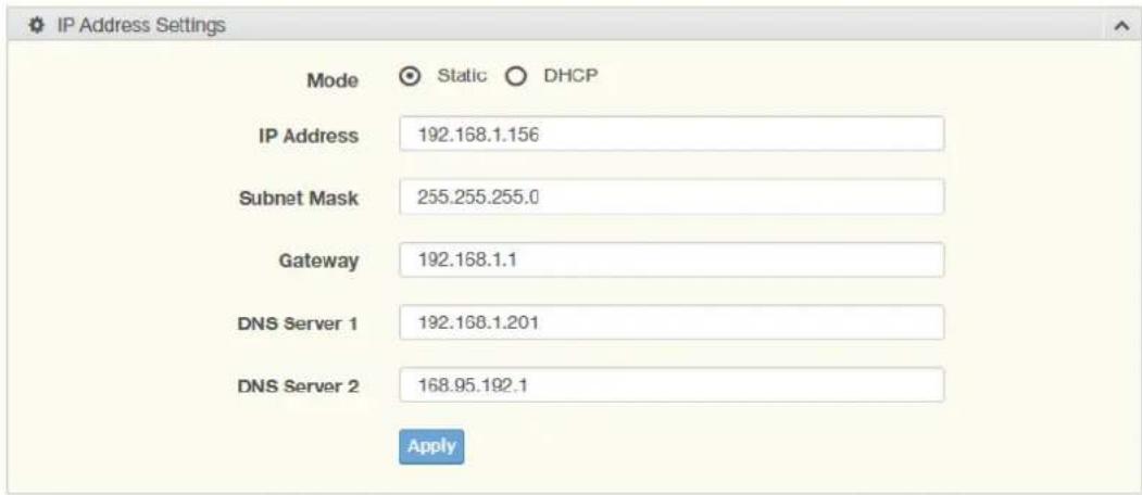
Figure 4.18 System > IP Settings
The following table describes the items in the previous figure.
| Item Description |
| Mode Click the radio button to select the IP Address Setting mode: Static or DHCP. |
| IP Address Enter a value to specify the IP address of the interface. The default is 192.168.1.1. |
| Subnet Mask Enter a value to specify the IP subnet mask for the interface. The default is 255.255.255.0. |
| Gateway Enter a value to specify the default gateway for the interface. The default is 192.168.1.254. |
| DNS Server 1 Enter a value to specify the DNS server 1 for the interface. The default is 168.95.1.1. |
| DNS Server 2 Enter a value to specify the DNS server 2 for the interface. The default is 168.95.192.1. |
| Apply Click Apply to save the values and update the screen. |
The following figure displays the IP Address Information settings
| Information Name | Information Value |
| DHCP State | Disabled |
| Current IP Address | 192.168.1.1 |
| Current Subnet Mask | 255.255.255.0 |
| Current Gateway | 192.168.1.254 |
| Current DNS Server 1 | 168.95.1.1 |
| Current DNS Server 2 | 168.95.192.1 |
| Static IP Address | 192.106.1.1 |
| Static Subnet Mask | 255.255.255.0 |
| Static Gateway | 192.106.1.254 |
| Static DNS Server 1 | 168.95.1.1 |
| Static DNS Server 2 | 168.95.192.1 |
Figure 4.19 System > IP Address Information
4.4.2 IPv6 Settings
To access this page, click System > IPv6 Settings.

Figure 4.20 System > IPv6 Settings
The following table describes the items in the previous figure.
| Item Description | |
| Auto Configuration Select the radio button to enable or disable the IPv6. | |
| IPv6 Address Enter the IPv6 address for the system. | |
| Gateway | Enter the gateway address for the system. |
| DHCPv6 Client | Enter the DHCPv6 address for the system. |
| Apply | Click Apply to save the values and update the screen. |
The ensuing table for IPv6 Information settings are informational only: Auto Configuration, IPv6 In Use Address, IPv6 In Use Router, IPv6 Static Address, IPv6 Static Router and DHCPv6 Client.
The following figure displays the IPv6 Information settings
| Information Name | Information Value |
| Auto Configuration | Enabled |
| IPv6 Link Local Address | fe60: c600:adff:fef2: 12c8 / 64 |
| IPv6 In Use Address | fe60: c600:adff:fef2: 12c8 / 64 |
| IPv6 In Use Router | - |
| IPv6 Static Address | /0 |
| IPv6 Static Router | - |
| DHCPv6 Client | Disabled |
Figure 4.21 System > IPv6 Information
4.4.3 DHCP Client Option 82
The DHCP Client Option 82 configurable Circuit ID and Remote ID feature enhances validation security by allowing you to select naming choices suboptions. You can select a switch-configured hostname or specify an ASCII test string for the remote ID. You can also configure an ASCII text string to override the circuit ID.
To access this page, click System > DHCP Client Option 82.
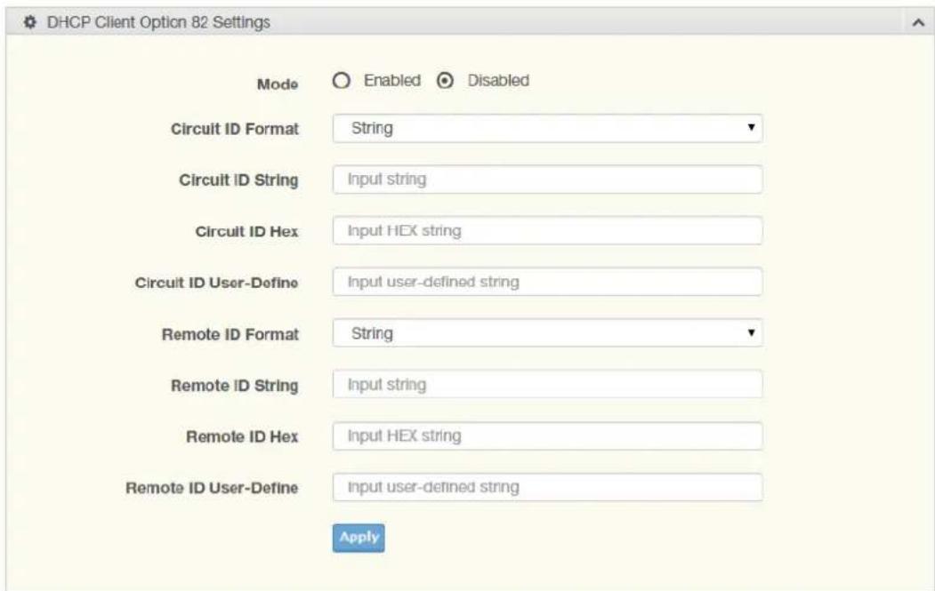
Figure 4.22 System > DHCP Client Option 82
The following table describes the items in the previous figure.
| Item Description | |
| Mode Click the radio button to enable or disable the DHCP Client Option 82 mode. | |
| Circuit ID Format Click the drop-down menu to set the ID format: String, Hex, User Definition. | |
| Circuit ID String Enter the string ID of the corresponding class. | |
| Circuit ID Hex Enter the hex string of the corresponding class. | |
| Circuit ID User-Define | Enter the user definition of the corresponding class. |
| Remote ID Format Click the drop-down menu to set the Remote ID format: String, Hex, User Definition. | |
| Remote ID String Enter the remote string ID of the corresponding class. | |
| Remote ID Hex Enter the remote hex string of the corresponding class. | |
| Remote ID User-Define | Enter the remote user definition of the corresponding class. |
| Apply Click Apply to save the values and update the screen. | |
The ensuing table for DHCP Client Option 82 Information table settings are informational only: Status, Circuit ID Format, Circuit ID String, Circuit ID Hex, Circuit ID User-Define, Remote ID Format, Remote ID String, Remote ID Hex and Remote ID User-Define.
The following figure displays the DHCP Client Option 82 Information settings
| DHCP Client Option 82 Information | |
| Information Name | Information Value |
| Status | Disabled |
| Circuit ID Format | String |
| Circuit ID String | |
| Circuit ID Hex | |
| Circuit ID User-Define | |
| Remote ID Format | String |
| Remote ID String | |
| Remote ID Hex | |
| Remote ID User-Define | |
Figure 4.23 System > DHCP Client Option 82 Information
4.4.4 DHCP Auto Provision
The DHCP Auto Provision feature allows you to load configurations using a server with DHCP options. Through the remote connection, the switch obtains information from a configuration file available through the TFTP server.
To access this page, click System > DHCP Auto Provision.

Figure 4.24 System > DHCP Auto Provision
The following table describes the items in the previous figure.
Item Description
Status Select the radio button to enable or disable the DHCP Auto Provisioning Setting.
Apply Click Apply to save the values and update the screen.
The following figure displays the DHCP Auto Provision Information settings
| Information Name | Information Value |
| Status | Disabled |
| Circuit ID Format | String |
| Circuit ID String | |
| Circuit ID Hex | |
| Circuit ID User-Define | |
| Remote ID Format | String |
| Remote ID String | |
| Remote ID Hex | |
| Remote ID User-Define |
Figure 4.25 System > DHCP Auto Provision Information
4.4.5 Management VLAN
By default the VLAN is the management VLAN providing communication with the switch management interface.
To access this page, click System > Management VLAN.

Figure 4.26 System > Management VLAN
The following table describes the items in the previous figure.
Item Description
Management VLAN Click the drop-down menu to select a defined VLAN.
Apply Click Apply to save the values and update the screen.
The ensuing table for Management VLAN State are informational only: Management VLAN.
4.4.6 System Time
To access this page, click System > System Time.
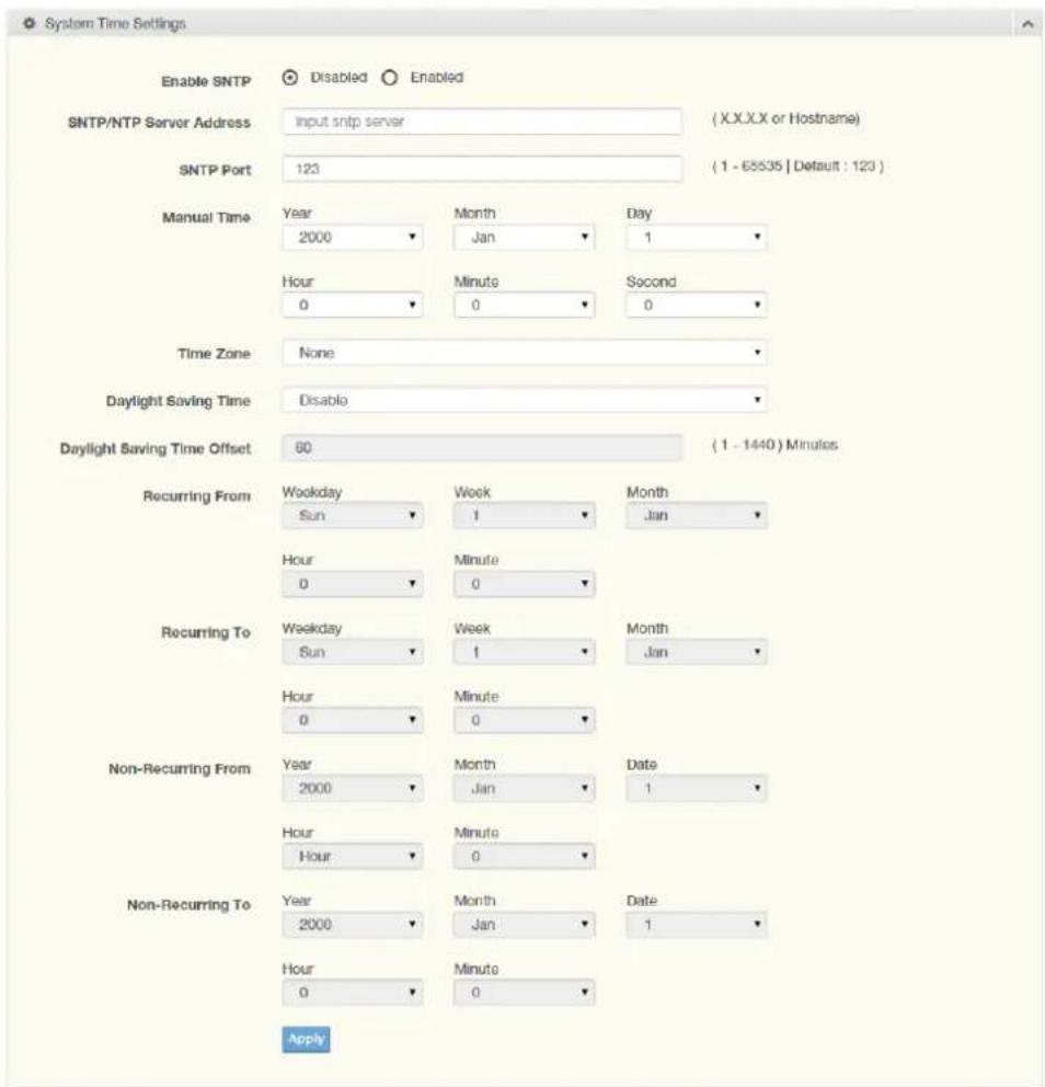
Figure 4.27 System > System Time
The following table describes the items in the previous figure.
Item Description
Enable SNTP Click the radio button to enable or disable the SNTP.
| Item Description | |
| SNTP/NTP Server Address | Enter the address of the SNTP server. This is a text string of up to 64 characters containing the encoded unicast IP address or hostname of a SNTP server. Unicast SNTP requests will be sent to this address. If this address is a DNS hostname, then that hostname should be resolved into an IP address each time a SNTP request is sent to it. |
| SNTP Port Enter the port on the server to which SNTP requests are to be sent. Allowed range is 1 to 65535 (default: 123). | |
| Manual Time Click the drop-down menus to set local date and time of the system. | |
| Time Zone Click the drop-down menu to select a system time zone. | |
| Daylight Saving Time Click the drop-down menu to enable or disable the daylight saving time settings. | |
| Daylight Saving Time Enter the offsetting variable in seconds to adjust for daylight saving time. Offset time. | |
| Recurring From Click the drop-down menu to designate the start date and time for daylight saving time. | |
| Recurring To Click the drop-down menu to designate the end date and time for daylight saving time. | |
| Non-Recurring From Click the drop-down menu to designate a start date and time for a non-recurring daylight saving time event. | |
| Non-Recurring To Click the drop-down menu to designate the end date and time for a non-recurring daylight saving time event. | |
| Apply Click Apply to save the values and update the screen. | |
The following figure displays the System Time Information settings
| Information Name | Information Value |
| Current Date/Time | 06 15 01 DFL(GMT+8) Jan 02 2000 |
| SNTP | Disabled |
| SNTP Server Address | |
| SNTP Server Port | 123 |
| Time zone | GMT+8 |
| Daylight Saving Time | Disabled |
| Daylight Saving Time Offset | |
| From | |
| To |
Figure 4.28 System > System Time Information
4.4.7 Network Port
To access this page, click System > Network Port.
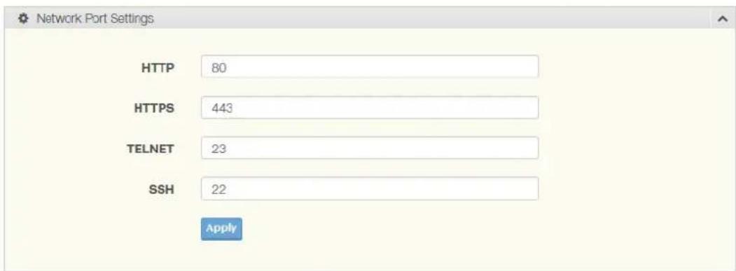
Figure 4.29 System > Network Port
The following table describes the items in the previous figure.
Item Description
| HTTP By default, the HTTPS port setting is set to port 80. To assign the web interface to a different port, enter the port number in the field. |
| HTTPS By default, the HTTPS port setting is set to port 443. To assign the web interface to a different port, enter the port number in the field. |
| TELNET By default, the TELNET port setting is set to port 23. To assign the web interface to a different port, enter the port number in the field. |
| SSH By default, the SSH port setting is set to port 22. To assign the web interface to a different port, enter the port number in the field. |
| Apply Click Apply to save the values and update the screen. |
The ensuing table for Network Port Information are informational only: HTTP, HTTPS, TELNET and SSH.
4.5 L2 Switching
4.5.1 Port Configuration
Port Configuration describes how to use the user interface to configure LAN ports on the switch.
To access this page, click L2 Switching > Port Configuration.
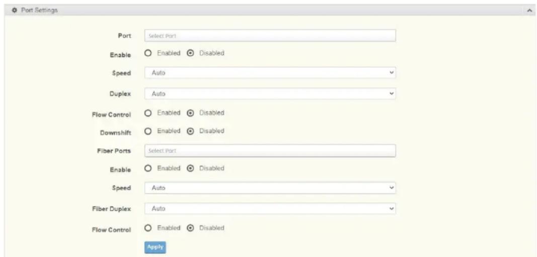
Figure 4.30 L2 Switching > Port Configuration
The following table describes the items in the previous figure.
Item Description
| Port Click the drop-down menu to select the port for the L2 Switch setting. |
| Enabled Click the radio-button to enable or disable the Port Setting function. |
| Speed Click the drop-down menu to select the port speed: Auto, Auto-10M, Auto-100M, Auto-1000M, Auto-10/100M, 10M, 100M, or 1000M. |
| Duplex Click the drop-down menu to select the duplex setting: Auto, Half or Full. |
| Flow Control Click the radio button to enable or disable the flow control function. |
| Downshift Click the radio button to enable or disable the downshift function for speed. |
| Fiber Port Click the drop-down menu to select the port for the L2 Switch Fiber port setting. |
| Enabled Click the radio-button to enable or disable the Fiber Port Setting function. |
| Speed Click the drop-down menu to select the fiber port speed: Auto, Auto-1000M, 100M, or 1000M. |
| Duplex Click the drop-down menu to select the duplex setting: Half or Full. |
| Flow Control Click the radio button to enable or disable the flow control function. |
| Apply Click Apply to save the values and update the screen. |
The following figure shows the Port Name Settings with Display Method.
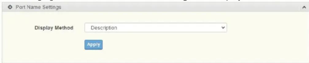
Figure 4.31 L2 Switching > Port Name Settings
The following figure displays the Port Status settings.
| Port | Description | Enable State | Link Status | Speed | Duplex | Down Shift | FlowCtrl Config | FlowCtrl Status |
| GE1 | Edit | Enabled | DOWN | Auto | Auto | Enabled | Disabled | Disabled |
| GE2 | Edit | Enabled | DOWN | Auto | Auto | Enabled | Disabled | Disabled |
| GE3 | Edit | Enabled | DOWN | Auto | Auto | Enabled | Disabled | Disabled |
| GE4 | Edit | Enabled | DOWN | Auto | Auto | Enabled | Disabled | Disabled |
| GE5 | Edit | Enabled | DOWN | Auto | Auto | Enabled | Disabled | Disabled |
| GE6 | Edit | Enabled | DOWN | Auto | Auto | Enabled | Disabled | Disabled |
| GE7 | Edit | Enabled | DOWN | Auto | Auto | Enabled | Disabled | Disabled |
Figure 4.32 L2 Switching > Port Status
4.5.2 Port Mirror
Port mirroring function allows the sending of a copy of network packets seen on one switch port to a network monitoring connection on another switch port. Port mirroring can be used to analyze and debug data or diagnose errors on a network or to mirror either inbound or outbound traffic (or both).
There are no preset values in the Port Mirror. The displayed values do not represent the actual setting values.
To access this page, click L2 Switching > Port Mirror.
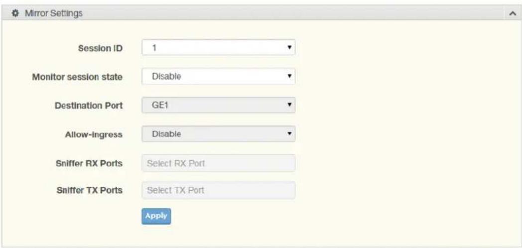
Figure 4.33 L2 Switching > Port Mirror
The following table describes the items in the previous figure.
| Item Description |
| Session ID Click the drop-down menu to select a port mirroring session from the list. The number of sessions allowed is platform specific. |
| Monitor session state Click the drop-down menu to enable or disable the session mode for a selected session ID. |
| Destination Port Click the drop-down menu to select the destination port and receive all the traffic from configured mirrored port(s). |
| Allow-ingress Click the drop-down menu to enable or disable the Allow-ingress function. |
Item Description
Sniffer RX Ports Enter the variable to define the RX port.
Sniffer TX Ports Enter the variable to define the TX port.
Apply Click Apply to save the values and update the screen.
RSPAN Settings allow you to analyze network traffic passing through VLANs or ports by using the RSPAN function to direct a copy of the traffic to a corresponding port.
The following figure displays the RSPAN settings.
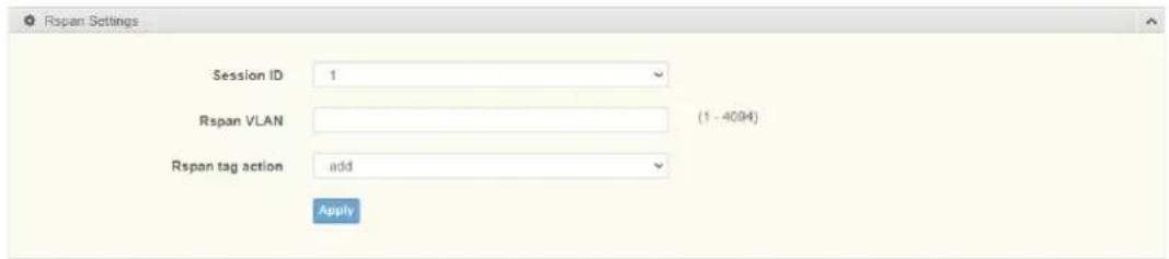
Figure 4.34 L2 Switching > RSPAN
Item Description
Session ID Enter the session ID for RSPAN
Rspan VLAN Enter the value to the corresponding Rspan VLAN ID
Rspan tag action Click to add, remove, and no-modify the entry.
Apply Click Apply to save the values and update the screen.
The following figure displays the Mirror Status settings.
| Session ID | Destination Port | Ingress State | Source TX Port | Source RX Port | Rspan VLAN | Rspan Tag Action |
| 1 | N/A | N/A | N/A | N/A | N/A | N/A |
| 2 | N/A | N/A | N/A | N/A | N/A | N/A |
| 3 | N/A | N/A | N/A | N/A | N/A | N/A |
| 4 | N/A | N/A | N/A | N/A | N/A | N/A |
Figure 4.35 L2 Switching > Mirror Status
4.5.3 Link Aggregation
Link Aggregation is a method for combining multiple network connections in parallel in order to increase throughput beyond the capability of a single connection, and to provide redundancy in case one of the links should fail.
4.5.3.1 Load Balance
The Load Balancing page allows you to select between a MAC Address or IP/MAC Address algorithm for the even distribution of IP traffic across two or more links.
To access this page, click L2 Switching > Link Aggregation > Load Balance.

Figure 4.36 L2 Switching > Link Aggregation > Load Balance
The following table describes the items in the previous figure.
Item Description
Load Balance Algorithm Select the radio button to select the Load Balance Setting: MAC Address, IP/MAC Address or Source Port.
Apply Click Apply to save the values and update the screen.
The following figure displays the Load Balance Information settings.
| Load Balance Information | |
| Information Name | Information Value |
| Load Balance Algorithm | src-dst-mac |
Figure 4.37 Switching > Link Aggregation > Load Balance Information
Link aggregation is also known as trunking. It is a feature available on the Ethernet gateway and is used with Layer 2 Bridging. Link aggregation allows for the logical merging of multiple ports into a single link.
To access this page, click L2 Switching > Link Aggregation > LAG Management.
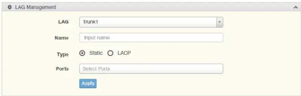
Figure 4.38 L2 Switching > Link Aggregation > LAG Management
The following table describes the items in the previous figure.
Item Description
LAG Click the drop-down menu to select the designated trunk group: Trunk 1 \~8.
Name Enter an entry to specify the LAG name.
Type Click the radio button to specify the type mode: Static or LACP.
Ports Click the drop-down menu to select designated ports: FE1-8 or GE1-2.
Apply Click Apply to save the values and update the screen.
The following figure displays the LAG Management Information settings.
| LAG Management Information | ||||||
| LAG | Name | Type | Link State | Active Member | Standby Member | Modify |
| Trunk1 | - | Not Present | - | - | Edit Clear | |
| Trunk2 | - | Not Present | - | - | Edit Clear | |
| Trunk3 | - | Not Present | - | - | Edit Clear | |
| Trunk4 | - | Not Present | - | - | Edit Clear | |
| Trunk5 | - | Not Present | - | - | Edit Clear | |
| Trunk8 | - | Not Present | - | - | Edit Clear | |
| Trunk7 | - | Not Present | - | - | Edit Clear | |
| Trunk8 | - | Not Present | - | - | Edit Clear | |
Figure 4.39 Switching > Link Aggregation > LAG Management Information
4.5.3.3 LAG Port Settings
The LAG Port Settings page allows you to enable or disable, set LAG status, speed and flow control functions.
In this example we will configure a LAG between the following switches:
To access this page, click L2 Switching > Link Aggregation > LAG Port Settings.
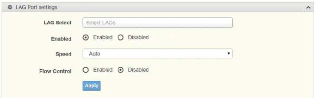
Figure 4.40 L2 Switching > Link Aggregation > LAG Port Settings
The following table describes the items in the previous figure.
Item Description
LAG Select Click the drop-down menu to select a predefined LAG trunk definition: LAG 1-8.
Enabled Click the radio button to enable or disable the LAG Port.
Speed Click the drop-down menu to select the port speed: Auto, Auto-10M, Auto-100M, Auto-1000M, Auto-10/100M, 10M, 100M, or 1000M.
Flow Control Click the radio button to enable or disable the Flow Control for the LAG Port.
Apply Click Apply to save the values and update the screen.
The following figure displays the LAG Port Status settings
| LAG Port Status | ||||||||
| LAG | Description | Port Type | Enable State | Link Status | Speed | Duplex | FlowCtrl Config | FlowCtrl Status |
| Trunk1 | Enabled | Auto | Auto | Disabled | Disabled | |||
| Trunk2 | Enabled | Auto | Auto | Disabled | Disabled | |||
| Trunk3 | Enabled | Auto | Auto | Disabled | Disabled | |||
| Trunk4 | Enabled | Auto | Auto | Disabled | Disabled | |||
| Trunk5 | Enabled | Auto | Auto | Disabled | Disabled | |||
| Trunk6 | Enabled | Auto | Auto | Disabled | Disabled | |||
| Trunk7 | Enabled | Auto | Auto | Disabled | Disabled | |||
| Trunk8 | Enabled | Auto | Auto | Disabled | Disabled | |||
Figure 4.41 Switching > Link Aggregation > LAG Port Status
4.5.3.4 LACP Priority Settings
The LACP Priority Settings page allows you to configure the system priority for LACP. To access this page, click L2 Switching > Link Aggregation > LACP Priority Settings.

Figure 4.42 L2 Switching > Link Aggregation > LACP Priority Settings
The following table describes the items in the previous figure.
Item Description
System Priority Enter the value (1-65535) to designate the LACP system priority.
Apply Click Apply to save the values and update the screen.
The ensuing table for LACP Information settings are informational only: System Priority.
4.5.3.5 LACP Port Settings
Link Aggregation Control Protocol (LACP) provides a method to control the bundling of several physical ports together to form a single logical channel. By configuring the LACP function, the switch can negotiate an automatic bundling of links by sending LACP packets to the peer device (also implementing LACP).
To access this page, click L2 Switching > Link Aggregation > LACP Port Settings.
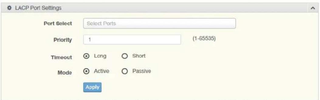
Figure 4.43 L2 Switching > Link Aggregation > LACP Port Settings
The following table describes the items in the previous figure.
Item Description
Port Select Select a port for the LACP Port Settings. The listed available settings are: FE1-FE8, GE1-GE2.
However, the available settings are dependent on the connected LACP device and may not be listed as displayed in the current figure.
Priority Enter a variable (1 to 65535) to assign a priority to the defined port selection.
Timeout Click the radio button to select a long or short timeout period.
Mode Click the radio button to select the setting mode: Active or Passive.
Active: Enables LACP unconditionally.
Passive: Enables LACP only when an LACP device is detected (default state).
Apply Click Apply to save the values and update the screen.
The following figure displays the LACP Port Information settings.
| Port Name | Priority | Timeout | Mode |
| GE1 | 1 | Long | Passive |
| GE2 | 1 | Long | Passive |
| GE3 | 1 | Long | Passive |
| GE4 | 1 | Long | Passive |
| GE5 | 1 | Long | Passive |
| GE6 | 1 | Long | Passive |
| GE7 | 1 | Long | Passive |
| GE8 | 1 | Long | Passive |
Figure 4.44 L2 Switching > Link Aggregation > LACP Port Information Settings
4.5.4 802.1Q VLAN
The 802.1Q VLAN feature allows for a single VLAN to support multiple VLANs. With the 802.1Q feature you can preserve VLAN IDs and segregate different VLAN traffic.
The 802.1Q VLAN tag feature encapsulates the 802.1Q VLAN tagging within another 802.1Q VLAN tag. The outer tag is assigned following the AP group, while the inner VLAN ID is assigned dynamically by the AAA server.
4.5.4.1 VLAN Management
The management of VLANs is available through the VLAN Settings page. Through this page you can add or delete VLAN listings and add a prefix name to an added entry.
To access this page, click L2 Switching > 802.1Q VLAN > VLAN Management.
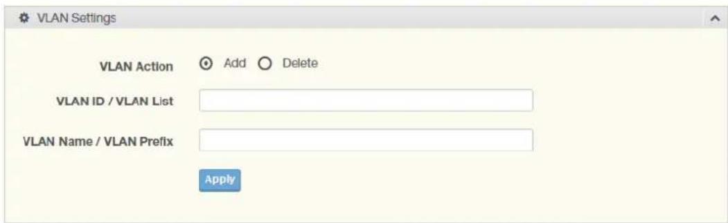
Figure 4.45 L2 Switching > 802.1Q VLAN > VLAN Management
The following table describes the items in the previous figure.
Item Description
VLAN Action Click the radio button to add or delete the VLAN entry shown in the previous field.
VLAN ID / VLAN List Enter the name of the VLAN entry to setup.
VLAN Name / VLAN Enter the prefix to be used by the VLAN list entry in the previous field. Prefix
Apply Click Apply to save the values and update the screen.
The following figure displays the VLAN Table settings.

Figure 4.46 L2 Switching > 802.1Q VLAN > VLAN Table
4.5.4.2 PVID Settings
The PVID Settings page allows you to designate a PVID for a selected port, define the accepted type and enable/disable the ingress filtering.
To access this page, click L2 Switching > 802.1Q VLAN > PVID Settings.
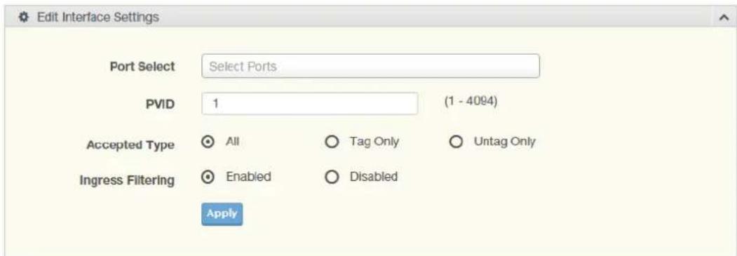
Figure 4.47 L2 Switching > 802.1Q VLAN > PVID Settings
The following table describes the items in the previous figure.
Item Description
Port Select Click the drop-down menu to select a port and edit its settings: FE1-FE8, GE1-GE2, or Trunk1 - Trunk8.
Item Description
| PVID Enter the VLAN ID you want assigned to untagged or priority taggedframes received on this port. The value ranges 1 to 4094. The default is 1. |
| Accepted Type Click the radio button to specify which frames to forward.Tag Only discards any untagged or priority tagged frames.Untag Only discards any tagged frames.All accepts all untagged and tagged frames.Whichever you select, VLAN tagged frames are forwarded in accordance with the IEEE 802.1Q VLAN standard. The default is All. |
| Ingress Filtering Click the radio button to specify how you want the port to handletagged frames. If you enable Ingress Filtering, a tagged frame will be discarded if this port is not a member of the VLAN identified by the VLAN ID in the tag. If you select Disabled, all tagged frames will be accepted. The default is Disabled. |
Apply Click Apply to save the values and update the screen.
The ensuing table for Port VLAN Status settings are informational only: Port, Interface VLAN Mode, PVID, Accept Frame Type and Ingress Filtering.
4.5.4.3 Port to VLAN
The Port to VLAN page allows you to add a port to a VLAN and select the related parameters.
To access this page, click L2 Switching > 802.1Q VLAN > Port to VLAN.
| Port to VLAN Table | |||
| Port | Interface VLAN Mode | Membership | PVID |
| GE1 | Hybrid | ○ Forbidden ○ Excluded ○ Tagged ○ Untagged | YES |
| GE2 | Hybrid | ○ Forbidden ○ Excluded ○ Tagged ○ Untagged | YES |
| GE3 | Hybrid | ○ Forbidden ○ Excluded ○ Tagged ○ Untagged | YES |
| GE4 | Hybrid | ○ Forbidden ○ Excluded ○ Tagged ○ Untagged | YES |
| GE5 | Hybrid | ○ Forbidden ○ Excluded ○ Tagged ○ Untagged | YES |
| GE6 | Hybrid | ○ Forbidden ○ Excluded ○ Tagged ○ Untagged | YES |
| GE7 | Hybrid | ○ Forbidden ○ Excluded ○ Tagged ○ Untagged | YES |
| GE8 | Hybrid | ○ Forbidden ○ Excluded ○ Tagged ○ Untagged | YES |
| GE9 | Hybrid | ○ Forbidden ○ Excluded ○ Tagged ○ Untagged | YES |
| GE10 | Hybrid | ○ Forbidden ○ Excluded ○ Tagged ○ Untagged | YES |
| Trunk1 | Hybrid | ○ Forbidden ○ Excluded ○ Tagged ○ Untagged | YES |
| Trunk2 | Hybrid | ○ Forbidden ○ Excluded ○ Tagged ○ Untagged | YES |
| Trunk3 | Hybrid | ○ Forbidden ○ Excluded ○ Tagged ○ Untagged | YES |
| Trunk4 | Hybrid | ○ Forbidden ○ Excluded ○ Tagged ○ Untagged | YES |
| Trunk5 | Hybrid | ○ Forbidden ○ Excluded ○ Tagged ○ Untagged | YES |
| Trunk6 | Hybrid | ○ Forbidden ○ Excluded ○ Tagged ○ Untagged | YES |
| Trunk7 | Hybrid | ○ Forbidden ○ Excluded ○ Tagged ○ Untagged | YES |
| Trunk8 | Hybrid | ○ Forbidden ○ Excluded ○ Tagged ○ Untagged | YES |

Figure 4.48 L2 Switching > 802.1Q VLAN > Port to VLAN
The following table describes the items in the previous figure.
Item Description
Port Displays the assigned port to the entry.
Interface VLAN Mode Displays the Hybrid mode to the listed VLAN port.
Membership Displays the assigned membership status of the port entry, options include: Forbidden, Excluded Tagged or Untagged.
Apply Click Apply to save the values and update the screen.
The following figure displays the Port-VLAN Mapping Table settings.
| Port | Mode | Administrative VLANs | Operational VLANs |
| GE1 | Hybrid | 1UP | 1UP |
| GE2 | Hybrid | 1UP | 1UP |
| GE3 | Hybrid | 1UP | 1UP |
| GE4 | Hybrid | 1UP | 1UP |
| GE5 | Hybrid | 1UP | 1UP |
| GE6 | Hybrid | 1UP | 1UP |
| GE7 | Hybrid | 1UP | 1UP |
| GE8 | Hybrid | 1UP | 1UP |
| GE9 | Hybrid | 1UP | 1UP |
| GE10 | Hybrid | 1UP | 1UP |
Figure 4.49 L2 Switching > 802.1Q VLAN > Port-VLAN Mapping
4.5.4.5 RSPAN VLAN
The RSPAN VLAN page allows user to process monitoring RSPAN feature of the VLAN. The following figure displays the RSPAN VLAN Table settings.

Figure 4.50 L2 Switching > 802.1Q VLAN > RSPAN VLAN Mapping
The following table describes the items in the previous figure.
| Item Description | |
| VLAN ID Click the drop-down menu to select the corresponding VLAN ID to map. | |
| Apply | Click Apply to save the values and update the screen. |
4.5.5 Q-in-Q
Q-in-Q is commonly referred as VLAN stacking in which VLANs are nested by adding two tags to each frame instead of one. Network service provider and users both can use VLANs and makes it possible to have more than the 4094 separate VLANs allowed by 802.1Q.
There are three ways in which a machine can be connected to a network carrying double-tagged 802.1ad traffic:
■ via a untagged port, where both inner and outer VLANs are handled by the switch or switches (so the attached machine sees ordinary Ethernet frames);
via a single-tagged (tunnel) port, where the outer VLAN only is handled by the switch (so the attached machine sees single-tagged 802.1Q VLAN frames); or
via a double-tagged (trunk) port, where both inner and outer VLANs are handled by the attached machine (which sees double-tagged 802.1ad VLAN frames).
4.5.5.1 Global Settings
The Global Settings page allows you to set the outer VLAN Ethertype setting.
To access this page, click L2 Switching > Q-in-Q > Global Settings.
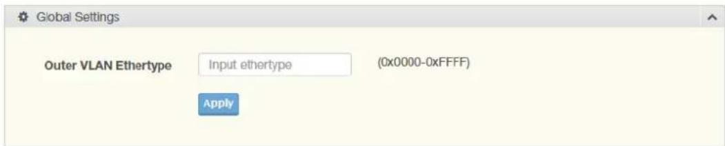
Figure 4.51 L2 Switching > Q-in-Q > Global Settings
The following table describes the items in the previous figure.
Item Description
Outer VLAN Ether-type Enter the outer VLAN handled by the switch giving the attached machine a single-tagged 802.1Q VLAN frame.
Apply Click Apply to save the values and update the screen.
The ensuing table for QinQ Global Information settings are informational only: Outer VLAN Ethertype.
4.5.5.2 Port Settings
The Port Settings page allows you to define the outer PVID and outer mode for a selected port.
To access this page, click L2 Switching > Q-in-Q > Port Settings.
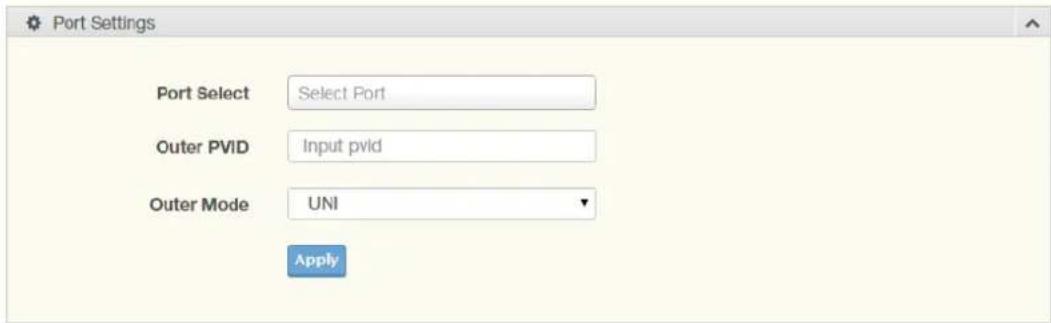
Figure 4.52 L2 Switching > Q-in-Q > Port Settings
The following table describes the items in the previous figure.
Item Description
Port Select Enter the switch port (part of VLAN configuration) to configure the selection as a tunnel port.
Outer PVID Enter the Port VLAN ID (PVID) to assigned the native VLAN ID. All untagged traffic coming in or out of the 802.1Q port is forwarded based on the PVID value
Outer Mode Click the drop-down menu to select between UNI or NNI role.
UNI: Selects a user-network interface which specifies communication between the specified user and a specified network.
■ NNI: Selects a network-to-network interface which specifies communication between two specified networks.
Apply Click Apply to save the values and update the screen.
The following figure displays the QinQ Port Information settings.
| Port | Outer PVID | Outer Mode |
| GE1 | 1 | UNI |
| GE2 | 1 | UNI |
| OE3 | 1 | UNI |
| GE4 | 1 | UNI |
| OE5 | 1 | UNI |
Figure 4.53 L2 Switching > QinQ Port Information
4.5.6 GARP
The Generic Attribute Registration Protocol (GARP) is a local area network (LAN) protocol. The protocol defines procedures for the registration and de-registration of attributes (network identifiers or addresses) by end stations and switches with each other.
4.5.6.1 GARP Settings
To access this page, click L2 Switching > GARP > GARP Settings.
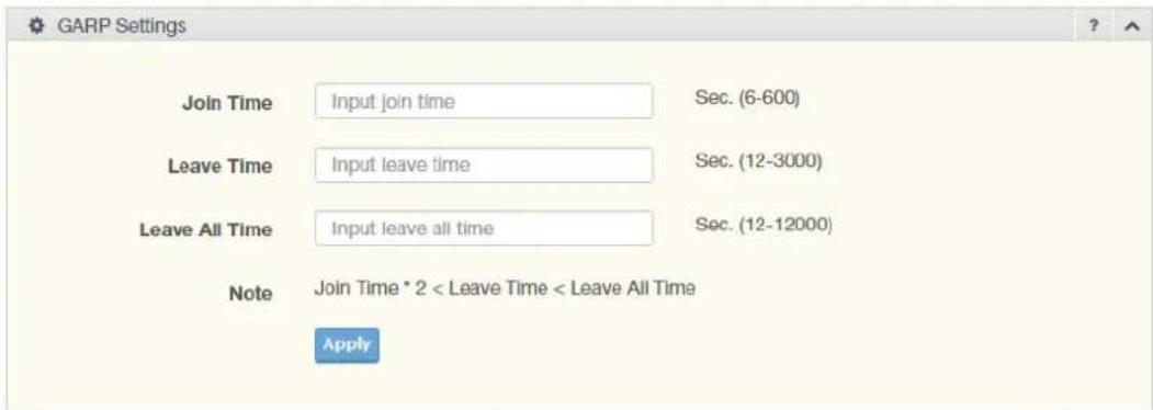
Figure 4.54 L2 Switching > GARP > GARP Settings
The following table describes the items in the previous figure.
| Item Description | |
| Join Time Enter a value to specify the time between the transmission of GARP PDUs registering (or re-registering) membership for a VLAN or multicast group in centiseconds. Enter a number between 6 and 600. An instance of this timer exists for each GARP participant for each port. | |
| Leave Time | Enter a value to specify the time to wait after receiving an unregister request for a VLAN or multicast group before deleting the associated entry, in centiseconds. This allows time for another station to assert registration for the same attribute in order to maintain uninterrupted service. Enter a number between 12 and 3000. An instance of this timer exists for each GARP participant for each port. |
| Leave All Time | Enter a value to specify the Leave All Time controls how frequently Leave All PDUs are generated. A LeaveAll PDU indicates that all registrations will shortly be deregistered. Participants will need to rejoin in order to maintain registration. The Leave All Period Timer is set to a random value in the range of LeaveAllTime to 1.5*LeaveAllTime. The timer is specified in centiseconds. Enter a number between 12 and 12000. An instance of this timer exists for each GARP participant for each port. |
| Apply | Click Apply to save the values and update the screen. |
The ensuing table for GARP Information settings are informational only: Join Time, Leave Time and Leave All Time.
4.5.6.2 GVRP Settings
The GVRP Settings page allows you to enable or disable the GVRP (GARP VLAN Registration Protocol or Generic VLAN Registration Protocol) protocol which facilitates control of virtual local area networks (VLANs) within a larger network.
To access this page, click L2 Switching > GARP > GVRP Settings.

Figure 4.55 L2 Switching > GARP > GVRP Settings
The following table describes the items in the previous figure.
| Item | Description |
| Status | Click to enable or disable the GARP VLAN Registration Protocol administrative mode for the switch. The factory default is Disable. |
| Apply | Click Apply to save the values and update the screen. |
The ensuing table for GVRP Information settings are informational only: GVRP.
4.5.6.3 GMRP Settings
To access this page, click L2 Switching > GARP > GMRP Settings.

Figure 4.56 L2 Switching > GARP > GMRP Settings
The following table describes the items in the previous figure.
| Item | Description |
| State | Click to enable or disable the GMRP mode for the switch. The factory default is Disable. |
| Apply | Click Apply to save the values and update the screen. |
The ensuing table for GMRP Information settings are informational only: GMRP.
The ensuing table for Multicast Groups settings are informational only: VLAN ID, MAC Address, Type and Member Ports.
4.5.7 802.3az EEE
The 802.3az Energy Efficient Ethernet (EEE) innovative green feature reduces energy consumption through intelligent functionality:
■ Traffic detection — Energy Efficient Ethernet (EEE) compliance
■ Inactive link detection
Inactive link detection function automatically reduces power usage when inactive links or devices are detected.
To access this page, click L2 Switching > 802.3az EEE.
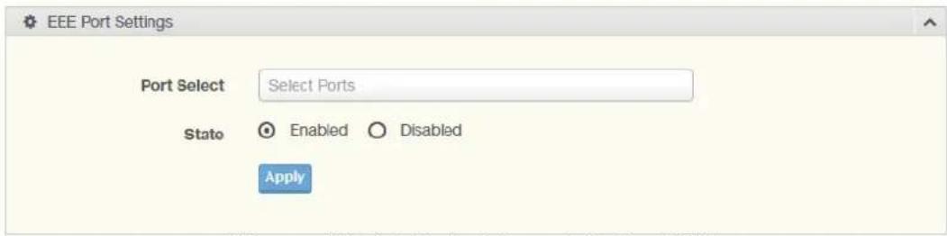
Figure 4.57 L2 Switching > 802.3az EEE
The following table describes the items in the previous figure.
| Item | Description |
| Port Select | Enter the port to setup the EEE function. |
| State | Click Enabled or Disabled to set the state mode of the port select setting. |
| Apply | Click Apply to save the values and update the screen. |
The ensuing table for EEE Enable Status settings are informational only: Port and EEE State.
4.5.8 Multicast
Multicast forwarding allows a single packet to be forwarded to multiple destinations. The service is based on L2 switch receiving a single packet addressed to a specific Multicast address. Multicast forwarding creates copies of the packet, and transmits the packets to the relevant ports.
4.5.8.1 Multicast Filtering
The Multicast Filtering page allows for the definition of action settings when an unknown multicast request is received. The options include: Drop, Flood, or Router Port.
To access this page, click L2 Switching > Multicast > Multicast Filtering.

Figure 4.58 L2 Switching > Multicast > Multicast Filtering
The following table describes the items in the previous figure.
| Item | Description |
| Unknown Multicast Action | Select the configuration protocol: Drop, Flood, or Router Port, to apply for any unknown multicast event. |
| Apply | Click Apply to save the values and update the screen. |
The ensuing table for Properties Information settings are informational only: Unknown Multicast Action.
4.5.8.2 IGMP Snooping
IGMP Snooping is defined as the process of listening to Internet Group Management Protocol (IGMP) network traffic. IGMP Snooping allows a network switch to listen in on the IGMP conversation between hosts and routers and maintain a map of which
links need which IP multicast streams. Multicasts can be filtered from the links which do not need them in turn controlling which ports receive specific multicast traffic.
IGMP Settings
To access this page, click L2 Switching > Multicast > IGMP Snooping > IGMP Settings.
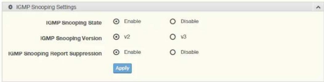
Figure 4.59 L2 Switching > Multicast > IGMP Snooping > IGMP Settings The following table describes the items in the previous figure.
| Item Description | |
| IGMP Snooping State | Select Enable or Disable to designate the IGMP Snooping State. |
| IGMP Snooping Version | Select designate the IGMP Snooping Version: V2 or V3. |
| IGMP Snooping Report Suppression | Select Enable or Disable to setup the report suppression for IGMP Snooping. |
| Apply Click Apply to save the values and update the screen. | |
The following figure displays the IGMP Snooping Information settings.
| IGMP Snooping Information | |
| Information Name | Information Value |
| IGMP Snooping State | Enable |
| IGMP Snooping Version | v2 |
| IGMP Snooping V2 Report Suppression | Enable |
Figure 4.60 L2 Switching > Multicast > IGMP Snooping > IGMP Snooping Information
IGMP Querier
IGMP Querier allows snooping to function by creating the tables for snooping. General queries must be unconditionally forwarded by all switches involved in IGMP snooping.
To access this page, click L2 Switching > Multicast > IGMP Snooping > IGMP Querier.
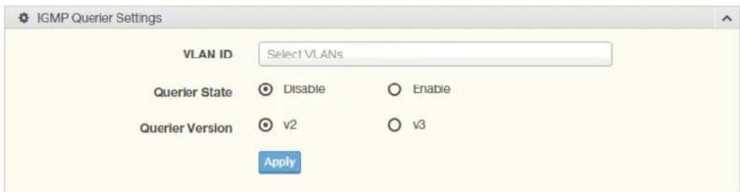
Figure 4.61 L2 Switching > Multicast > IGMP Snooping > IGMP Querier The following table describes the items in the previous figure.
Item Description
VLAN ID Select the VLAN ID to define the local IGMP querier.
Item Description
Querier State Select Disable or Enable to configure the VLAN ID (IGMP Querier).
Querier Version Select the querier version (V2 or V3) designated to the selected VLAN ID.
Apply Click Apply to save the values and update the screen.
The following figure displays the IGMP Querier Status settings.
| VLAN ID | Querier State | Querier Status | Querier Version | Querier IP |
| 1 | disabled | Non-Querier | ... | ... |
Figure 4.62 L2 Switching > Multicast > IGMP Snooping > IGMP Querier Status IGMP Static Groups
To access this page, click L2 Switching > Multicast > IGMP Snooping > IGMP Static Groups.
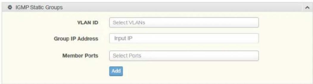
Figure 4.63 L2 Switching > Multicast > IGMP Snooping > IGMP Static Groups The following table describes the items in the previous figure.
Item Description
VLAN ID Select the VLAN ID to define IGMP static group.
| Group IP Address | Enter the IP address assigned to the VLAN ID. |
| Member Ports | Enter the port numbers to associate with the static group. |
| Add | Click Add to add an IGMP group. |
The ensuing table for IGMP Static Groups Status settings are informational only: VLAN ID, Group IP Address, Member Ports and Modify.
Multicast Groups
To access this page, click L2 Switching > Multicast > IGMP Snooping > Multicast Groups.
The following figure displays the Multicast Groups settings.

Figure 4.64 L2 Switching > Multicast > IGMP Snooping > Multicast Groups Router Ports
To access this page, click L2 Switching > Multicast > IGMP Snooping > Router Ports.
The following figure displays the Router Ports settings.
| VLAN ID | Port | Expiry Time (Sec) |
Figure 4.65 L2 Switching > Multicast > IGMP Snooping > Router Ports
4.5.8.3 MLD Snooping
The MLD Snooping page allows you to select the snooping status (enable or disable), the version (v1 or v2) and the enabling/disabling of the report suppression for the MLD querier, which sends out periodic general MLD queries and are forwarded through all ports in the VLAN.
MLD Settings
To access this page, click L2 Switching > Multicast > MLD Snooping > MLD Settings.
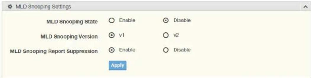
Figure 4.66 L2 Switching > Multicast > MLD Snooping > MLD Settings
The following table describes the items in the previous figure.
Item Description
| MLD Snooping State | Select Enable or Disable to setup the MLD Snooping State. |
| MLD Snooping Version | Select the querier version (V1 or V2) designated to the MLD Snooping Version. |
| MLD Snooping Report Suppression | Select Enable or Disable to designate the status of the report suppression. |
Apply Click Apply to save the values and update the screen.
The following figure displays the MLD Snooping Information settings.

Figure 4.67 L2 Switching > Multicast > MLD Snooping > MLD Snooping Information
The following figure displays the MLD Snooping Table settings.
| MLD Snooping Table | ||||||||||
| Entry No. | VLAN ID | MLD Snooping Operation State | Router Ports Auto Learn | Query Robustness | Query Interval(sec.) | Query Max Response interval(sec.) | Last Member Query count | Last Member Query Interval(sec) | Immediate Leave | Modify |
| 1 | 1 | disabled | enabled | 2 | 125 | 10 | 2 | 1 | disabled | Eats |
Figure 4.68 L2 Switching > Multicast > MLD Snooping > MLD Snooping Table
MLD Querier
The MLD Querier page allows you to select and enable/disable the MLD querier and define the version (IGMPv1 or IGMPv2) when enabled.
To access this page, click L2 Switching > Multicast > MLD Snooping > MLD Que-rier.
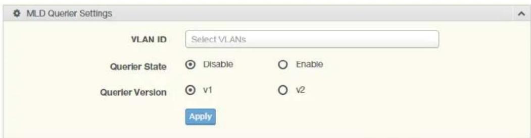
Figure 4.69 L2 Switching > Multicast > MLD Snooping > MLD Querier
The following table describes the items in the previous figure.
| Item Description | |
| VLAN ID Enter the VLAN ID to configure. | |
| Querier State Select Enable or Disable status on the selected VLAN.■ Enable: Enable IGMP Querier Election.■ Disable: Disable IGMP Querier Election. | |
| Querier Version Select the querier version (IGMPV1 or IGMPV2) designated to the MLD Querier function. | |
| Apply | Click Apply to save the values and update the screen. |
The ensuing table for MLD Querier Status settings are informational only: VLAN ID, Querier State, Querier Status, Querier Version and Querier IP.
MLD Static Group
The MLD Static Group page allows you to configure specified ports as static member ports.
To access this page, click L2 Switching > Multicast > MLD Snooping > MLD Static Group.
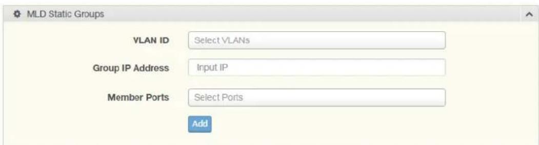
Figure 4.70 L2 Switching > Multicast > MLD Snooping > MLD Static Group
The following table describes the items in the previous figure.
| Item Description | |
| VLAN ID Enter the VLAN ID to define the local MLD Static Group. | |
| Group IP Address | Enter the IP address associated with the static group. |
| Member Ports | Enter the ports designated with the static group. |
| Add | Click Add to add a MLD static group. |
The ensuing table for MLD Static Groups Status settings are informational only: VLAN ID, Group IP Address, Member Ports and Modify.
Multicast Groups
To access this page, click L2 Switching > Multicast > MLD Snooping > Multicast Groups.
The following figure displays the Multicast Groups settings.

Figure 4.71 L2 Switching > Multicast > MLD Snooping > Multicast Groups
Router Ports
To access this page, click L2 Switching > Multicast > MLD Snooping > Router Ports.
The following figure displays the Router Ports settings.
| VLAN ID | Port | Expiry Time (Sec) |
Figure 4.72 L2 Switching > Multicast > MLD Snooping > Router Ports
4.5.9 Jumbo Frame
Jumbo frames are frames larger than the standard Ethernet frame size of 1518 bytes. The Jumbo Frame function allows the configuration of Ethernet frame size.
To access this page, click L2 Switching > Jumbo Frame.
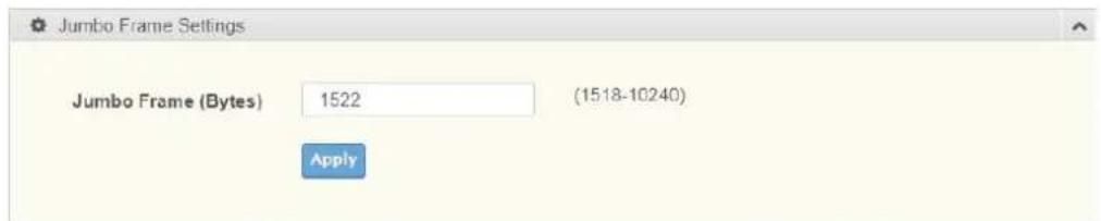
Figure 4.73 L2 Switching > Jumbo Frame
The following table describes the items in the previous figure.
| Item | Description |
| Jumbo Frame (Bytes) | Enter the variable in bytes (1518 to 10240) to define the jumbo frame size. |
| Apply | Click Apply to save the values and update the screen. |
The ensuing table for Jumbo Frame Config settings are informational only: Jumbo Frame (Bytes).
4.5.10 Spanning Tree
The Spanning Tree Protocol (STP) is a network protocol to ensure loop-free topology for any bridged Ethernet local area network.
4.5.10.1 STP Global Settings
The STP Global Settings page allows you to set the STP status, select the configuration for a BPDU packet, choose the path overhead, force version and set the configuration revision range.
To access this page, click L2 Switching > Spanning Tree > STP Global Settings.
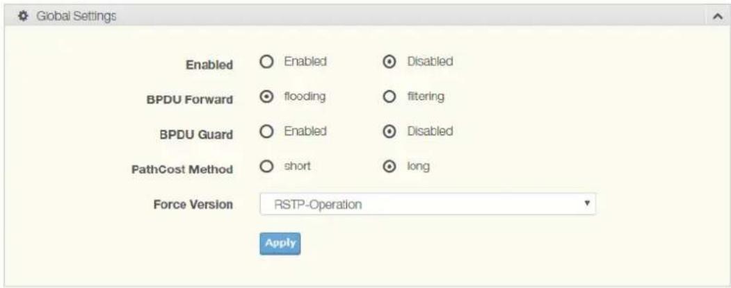
Figure 4.74 L2 Switching > Spanning Tree > STP Global Settings
The following table describes the items in the previous figure.
| Item Description | |
| Enabled Click the radio-button to enable or disable the STP status. | |
| BPDU Forward | Selectfloodingor filteringto designate the type of BPDU packet. |
| BPDU Guard Click the radio-button to enable or disable the BPDU guard. When enabled, BPDU Guard can disable edge ports that receive BPDU packets. This prevents a new device from entering the existing STP topology. Thus devices that were originally not a part of STP are not allowed to influence the STP topology | |
| PathCost Method Select short or long to define the method of used for path cost calculations. | |
| Force Version Click the drop-down menu to select the operating mode for STP.■STP-Compatible: 802.1D STP operation.■RSTP-Operation: 802.1w operation.■MSTP-Operation: 802.1s operation. | |
| Apply | ClickApplyto save the values and update the screen. |
The following figure displays the STP Information settings.
| Information Name | Information Value |
| STP | Disabled |
| BPOU Forward | flooding |
| BPDU Guard | Disabled |
| PathCost Method | long |
| Force Version | RSTP-Operation |
Figure 4.75 L2 Switching > Spanning Tree > STP Information
4.5.10.2 STP Port Settings
The STP Port Settings page allows you to configure the ports for the setting, port's contribution, configure edge port, and set the status of the BPDU filter.
To access this page, click L2 Switching > Spanning Tree > STP Port Settings.
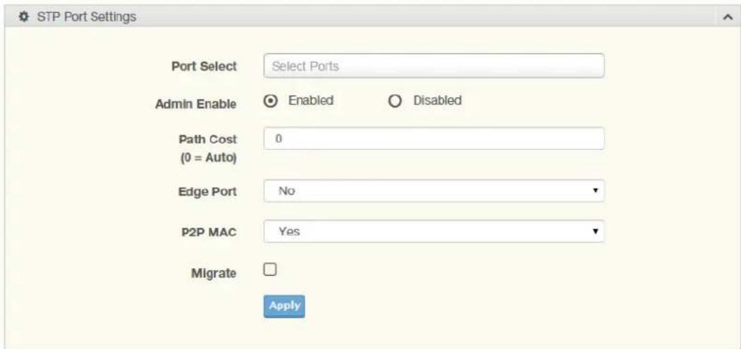
Figure 4.76 L2 Switching > Spanning Tree > STP Port Settings
The following table describes the items in the previous figure.
| Item Description | |
| Port Select Select the port list to specify the ports that apply to this setting. | |
| Admin Enable | Select Enabled or Disabled to setup the admin profile for the STP port. |
| Path Cost (0 = Auto) Set the port's cost contribution. For a root port, the root path cost for the bridge. (0 means Auto). | |
| Edge Port Click the drop-down menu to set the edge port configuration.■ No: Force to false state (as link to a bridge).■ Yes: Force to true state (as link to a host). | |
| P2P MAC | Click the drop-down menu to set the Point-to-Point port configuration.■ No: Force to false state.■ Yes: Force to true state. |
| Migrate | Click the check box to enable the migrate function.Forces the port to use the new MST/RST BPDUs, requiring the switch to test on the LAN segment. for the presence of legacy devices, which are not able to understand the new BPDU formats. |
| Apply | Click Apply to save the values and update the screen. |
The ensuing table for STP Port Status settings are informational only: Port, Admin Enable, Path Cost, Edge Port and P2P MAC.
4.5.10.3 STP Bridge Settings
The STP Bridge Settings page allows you to configure the priority, forward delay, maximum age, Tx hold count, and the hello time for the bridge.
To access this page, click L2 Switching > Spanning Tree > STP Bridge Settings.
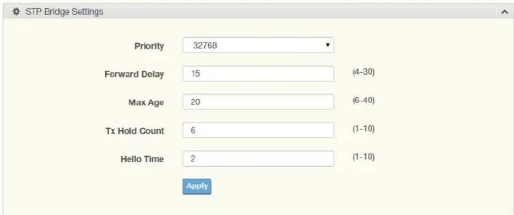
Figure 4.77 L2 Switching > Spanning Tree > STP Bridge Settings
The following table describes the items in the previous figure.
| Item Description | |
| Priority Click the drop-down menu to select the STP bridge priority. | |
| Forward Delay | Enter the variable (4 to 30) to set the forward delay for STP bridge settings. |
| Max Age | Enter the variable (6 to 40) to set the Max age for STP bridge settings. |
| Tx Hold Count | Enter the variable (1 to 10) to designate the TX hold count for STP bridge settings. |
| Hello Time | Enter the variable (1 to 10) to designate the Hello Time for STP bridge settings. |
| Apply | Click Apply to save the values and update the screen. |
The ensuing table for STP Bridge Information settings are informational only: Priority, Forward Delay, Max Age, Tx Hold Count and Hello Time.
The ensuing table for STP Bridge Status settings are informational only: Bridge Identifier, Designated Root Bridge, Root Path Cost, Designated Bridge, Root Port and Last Topology Change.
4.5.10.4 STP Port Advanced Settings
The STP Port Advanced Settings page allows you to select the port list to apply this setting.
To access this page, click L2 Switching > Spanning Tree > STP Port Advanced Settings.
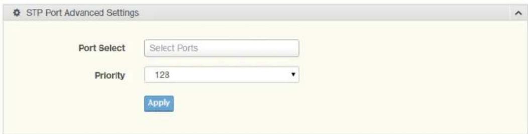
Figure 4.78 L2 Switching > Spanning Tree > STP Port Advanced Settings
The following table describes the items in the previous figure.
| Item Description | |
| Port Select | Select the port to designate the STP settings. |
Item Description
Priority Click the drop-down menu to designate a priority.
Apply Click Apply to save the values and update the screen.
The following figure displays the STP Port Status settings.
| Port | Identifier(Priority / Port Id) | Path CostConf/Oper | Designated Root Bridge | Root Path Cost | Designated Bridge | Edge PortConf/Oper | P2P MACConf/Oper | Port Role | Port State |
| GE1 | 128 / 1 | 0 / 20000 | 0 / 00.00.00.00.00.00 | 0 | 0 / 00.00.00.00.00.00 | No / No | No / No | Disabled | Disabled |
| GE2 | 128 / 2 | 0 / 20000 | 0 / 00.00.00.00.00.00 | 0 | 0 / 00.00.00.00.00.00 | No / No | No / No | Disabled | Disabled |
| GE3 | 128 / 3 | 0 / 20000 | 0 / 00.00.00.00.00.00 | 0 | 0 / 00.00.00.00.00.00 | No / No | No / No | Disabled | Disabled |
| GE4 | 128 / 4 | 0 / 20000 | 0 / 00.00.00.00.00.00 | 0 | 0 / 00.00.00.00.00.00 | No / No | No / No | Disabled | Disabled |
| GE5 | 128 / 5 | 0 / 20000 | 0 / 00.00.00.00.00.00 | 0 | 0 / 00.00.00.00.00.00 | No / No | No / No | Disabled | Disabled |
| GE6 | 128 / 6 | 0 / 20000 | 0 / 00.00.00.00.00.00 | 0 | 0 / 00.00.00.00.00.00 | No / No | No / No | Disabled | Disabled |
| GE7 | 128 / 7 | 0 / 20000 | 0 / 00.00.00.00.00.00 | 0 | 0 / 00.00.00.00.00.00 | No / No | No / No | Disabled | Disabled |
| GE8 | 128 / 8 | 0 / 20000 | 0 / 00.00.00.00.00.00 | 0 | 0 / 00.00.00.00.00.00 | No / No | No / No | Disabled | Disabled |
Figure 4.79 Switching > Spanning Tree > STP Port Status
4.5.10.5 MST Config Identification
The MST Config Identification page allows you to configure the identification setting name and the identification range.
To access this page, click L2 Switching > Spanning Tree > MST Config Identification.
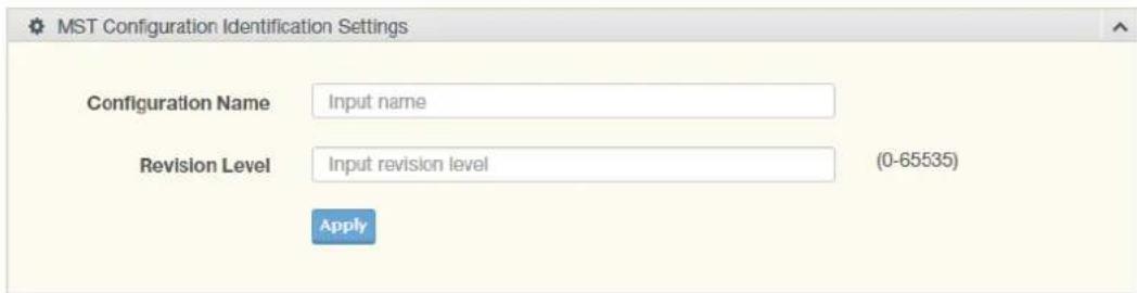
Figure 4.80 L2 Switching > Spanning Tree > MST Config Identification
The following table describes the items in the previous figure.
Item Description
Configuration Name Enter the identifier used to identify the configuration currently being used. It may be up to 32 characters.
Revision Level Enter the identifier for the Revision Configuration, range: 0 to 65535 (default: 0).
Apply Click Apply to save the values and update the screen.
The ensuing table for MST Configuration Identification Information settings are informational only: Configuration Name and Revision Level.
4.5.10.6 MST ID Settings
The MST Instance ID Settings page allows you to edit the MSTI ID and VID List settings.
To access this page, click L2 Switching > Spanning Tree > MST ID Settings.
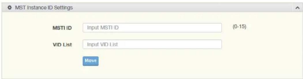
Figure 4.81 L2 Switching > Spanning Tree > MST ID Settings
The following table describes the items in the previous figure.
Item Description
MSTI ID Enter the MST instance ID (0-15).
VID List Enter the pre-configured VID list.
Move Click Move to save the values and update the screen.
The ensuing table for MST ID Information settings are informational only: MSTI ID and VID List.
4.5.10.7 MSTI Priority Settings
The MST Instance Priority Settings allows you to specify the MST instance and the bridge priority in that instance.
To access this page, click L2 Switching > Spanning Tree > MSTI Priority Settings.
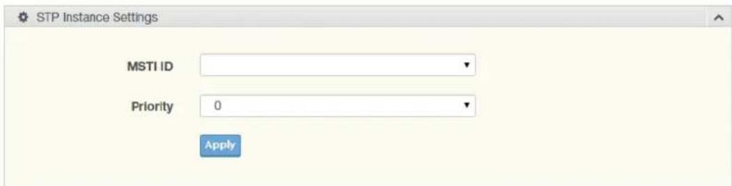
Figure 4.82 L2 Switching > Spanning Tree > MSTI Priority Settings
The following table describes the items in the previous figure.
Item Description
MSTI ID Click the drop-down menu to specify the MST instance.
| Priority | Click the drop-down menu set the bridge priority in the specified MST instance |
| Apply | Click Apply to save the values and update the screen. |
The ensuing table for MSTI Priority Information settings are informational only: MSTI ID, Priority and Action.
4.5.10.8 MSTI Bridge Info
To access this page, click L2 Switching > Spanning Tree > MSTI Bridge Info.
The following figure displays the STP Bridge Status settings.
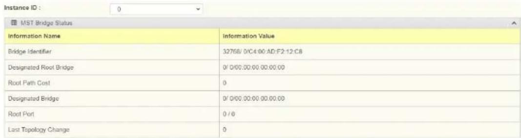
Figure 4.83 L2 Switching > Spanning Tree > STP Bridge Status
4.5.10.9 MSTI Port Advanced settings
To access this page, click L2 Switching > Spanning Tree > MSTI Port Advanced. The following figure displays the MSTI Port Advanced settings.
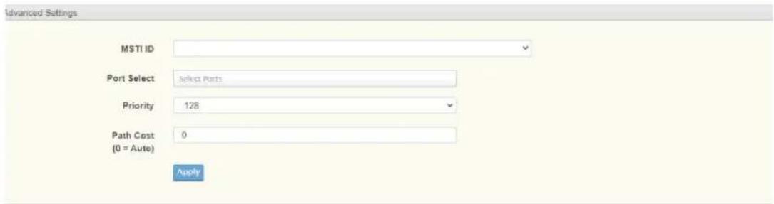
Figure 4.84 L2 Switching > Spanning Tree > MSTI Port Advanced settings
4.5.10.10 STP Statistics
To access this page, click L2 Switching > Spanning Tree > STP Statistics. The following figure displays the STP Statistics settings.
| Port | Configuration BPDUs Received | TCN BPDUs Received | Configuration BPDUs Transmitted | TCN BPDUs Transmitted |
| GE1 | 0 | 0 | 0 | 0 |
| GE2 | 0 | 0 | 0 | 0 |
| GE3 | 0 | 0 | 0 | 0 |
| GE4 | 0 | 0 | 0 | 0 |
| GE5 | 0 | 0 | 0 | 0 |
| GE6 | 0 | 0 | 0 | 0 |
| GE7 | 0 | 0 | 0 | 0 |
| GE8 | 0 | 0 | 0 | 0 |
| GE9 | 0 | 0 | 0 | 0 |
Figure 4.85 L2 Switching > Spanning Tree > STP Statistics
4.5.11 X-Ring Elite
The X-Ring Elite function provides an improvement over Spanning Tree and Rapid Spanning Tree and a rapid auto recovery in the event that the network suffers a corrupt or broken link and prevents network loops.
4.5.11.1 X-Ring Elite Settings
The X-Ring Elite Settings allows you to enable or disable the state of the X-Ring settings.
To access this page, click L2 Switching > X-Ring Elite > X-Ring Elite Settings.

Figure 4.86 L2 Switching > X-Ring Elite > X-Ring Elite Settings
The following table describes the items in the previous figure.
Item Description
State Select Enabled or Disabled to setup the X-Ring Elite mode.
Apply Click Apply to save the values and update the screen.
The ensuing table for Information settings are informational only: X-Ring Elite State.
4.5.11.2 X-Ring Elite Groups
The X-Ring Elite Groups page allows you to select the function and role for each device and the connected ports.
To access this page, click L2 Switching > X-Ring Elite > X-Ring Elite Groups.

Figure 4.87 L2 Switching > X-Ring Elite > X-Ring Elite Groups
The following table describes the items in the previous figure.
Item Description
Ring ID Enter a number to specifies a ranging from 1 to 255 to identify a given X-Ring Elite group.
Role Click the drop-down menu to select the ring role.
Port 1 Click the drop-down menu to define the port designation.
Port 2 Click the drop-down menu to define the port designation.
Add Click Add to save the values and update the screen.
The ensuing table for Information settings are informational only: Ring ID, Role, Port 1, Port 2 and Delete (click to delete the desired Ring ID).
4.5.12 X-Ring Pro
The X-Ring Pro function provides an improvement over Spanning Tree and Rapid Spanning Tree and a rapid auto recovery in the event that the network suffers a corrupt or broken link and prevents network loops.
4.5.12.1 X-Ring Pro Settings
The X-Ring Pro Settings page allows you to configure the status (enabled or disabled) of the function.
To access this page, click L2 Switching > X-Ring Pro > X-Ring Pro Settings.

Figure 4.88 L2 Switching > X-Ring Pro > X-Ring Pro Settings
The following table describes the items in the previous figure.
Item Description
State Select Enabled or Disabled to setup the X-Ring Pro mode.
Apply Click Apply to save the values and update the screen.
The ensuing table for Information settings are informational only: X-Ring Pro State.
4.5.12.2 X-Ring Pro Groups
The X-Ring Pro Groups page allows you to select the function and role for each ring ID and its connected ports.
To access this page, click L2 Switching > X-Ring Pro > X-Ring Pro Groups.

Figure 4.89 L2 Switching > X-Ring Pro > X-Ring Pro Groups > X-Ring Pro Groups Settings
The following table describes the items in the previous figure.
Item Description
Ring ID Enter a number to specifies a ranging from 1 to 255 to identify a given X-Ring Pro group.
Port 1 Click the drop-down menu to define the port designation.
Port 2 Click the drop-down menu to define the port designation.
Add Click Add to save the values and update the screen.

Figure 4.90 L2 Switching > X-Ring Pro > X-Ring Pro Groups > Chain Settings
The following table describes the items in the previous figure.
Item Description
Chain Ring ID Enter a number to specifies a ranging from 1 to 255 to identify a chain ring ID.
Role Click the drop-down menu to select the ring role.
Head Port Click the drop-down menu to define the port designation.
Item Description
Member Port Click the drop-down menu to define the port designation.
Add Click Add to save the values and update the screen.

Figure 4.91 L2 Switching > X-Ring Pro > X-Ring Pro Groups > Couple Setting
The following table describes the items in the previous figure.
Item Description
Couple Ring ID Enter a number to specifies a ranging from 1 to 255 to identify a given X-Ring group.
Port Enter the port to assign to define the couple setting.
Master Ring ID Click the drop-down menu to designate the master ring.
Add Click Add to save the values and update the screen.

Figure 4.92 L2 Switching > X-Ring Pro > X-Ring Pro Groups > Pair Settings
The following table describes the items in the previous figure.
Item Description
Pair Ring ID Enter a number to specifies a ranging from 1 to 255 to identify a pair ring ID.
Port Enter the port to assign to define the couple setting.
Master Ring ID Click the drop-down menu to designate the master ring.
Add Click Add to save the values and update the screen.

Figure 4.93 L2 Switching > X-Ring Pro > X-Ring Pro Groups > RPair Settings
The following table describes the items in the previous figure.
Item Description
RPair Ring ID Enter a number to specifies a ranging from 1 to 255 to identify a rpair ring ID.
Port Enter the port to assign to define the couple setting.
Item Description
Master Ring ID Click the drop-down menu to designate the master ring.
Add Click Add to save the values and update the screen.
The ensuing table for Information settings are informational only: Ring ID, Mode, Role, Operation State, Port 1, Forwarding State, Port 2, Forwarding State and Delete (click to delete the desired Ring ID).
4.5.13 Loopback Detection
The Loopback Detection function is used to detect looped links. By sending detection frames and then checking to see if the frames returned to any port on the device, the function is used to detect loops.
4.5.13.1 Global Settings
The Global Settings page allows you to configure the state (enabled or disabled) of the function, select the interval at which frames are transmitted and the delay before recovery.
To access this page, click L2 Switching > Loopback Detection > Global Settings.
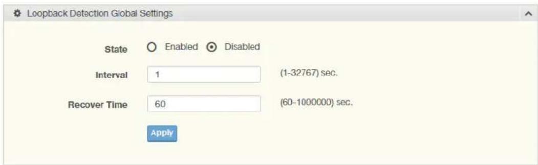
Figure 4.94 L2 Switching > Loopback Detection > Global Settings
The following table describes the items in the previous figure.
Item Description
| State | Select Enabled or Disabled to setup the loopback mode. |
| Interval | Enter the variable in seconds (1 to 32767) to set the interval at which frames are transmitted. |
| Recover Time | Enter the variable in seconds (60 to 1000000) to define the delay before recovery. |
| Apply | Click Apply to save the values and update the screen. |
To access this page, click L2 Switching > Loopback Detection > Loopback Detection Global Information.
The following figure displays the Loopback Detection Global Information settings.
| Loopback Detection Global Information | |
| Information Name | Information Value |
| State | Disabled |
| Interval | 1 |
| Recover Time | 60 |
Figure 4.95 L2 Switching > Loopback Detection > Loopback Detection Global Information
4.5.13.2 Port Settings
The Port Settings page allows you to select ports that are detected by the loopback detection function and configure their status (enabled or disabled).
To access this page, click L2 Switching > Loopback Detection > Port Settings.
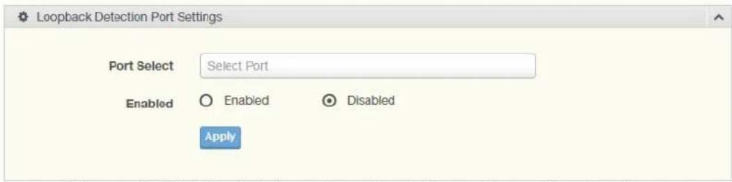
Figure 4.96 L2 Switching > Loopback Detection > Port Settings
The following table describes the items in the previous figure.
Item Description
Port Select Enter the port to define the local loopback detection setting.
| Enabled | Select Enabled or Disabled to setup the Loopback Detection function. |
| Apply Click Apply to save the values and update the screen. | |
The ensuing table for Loopback Detection Port Information settings are informational only: Port, Enable State and Loop Status.
4.5.14 ERPS
4.5.14.1 ERPS Settings
To access this page, click L2 Switching > ERPS > ERPS Settings.

Figure 4.97 L2 Switching > ERPS > ERPS Settings
The following table describes the items in the previous figure.
Item Description
State Click Enabled or Disabled to enable ERPS settings.
Apply Click Apply to save the values and update the screen.
The ensuing table for Information settings are informational only: ERPS State.
4.5.14.2 ERPS Groups
To access this page, click L2 Switching > ERPS > ERPS Groups.
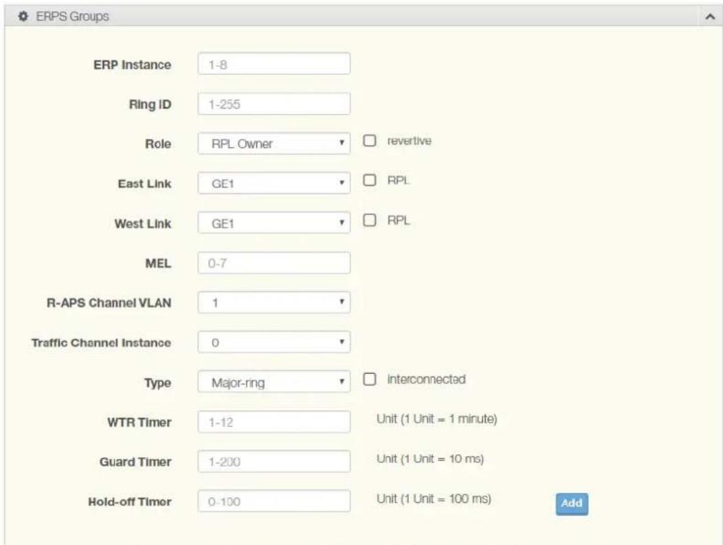
Figure 4.98 L2 Switching > ERPS > ERPS Groups
The following table describes the items in the previous figure.
| Item Description | |
| ERP Instance Enter the value to set the ERP instance. | |
| Ring ID Enter the value to set the ring ID. | |
| Role Click the drop down menu to select the role. Options include: RPL Owner, RPL Neighbor or Other. | |
| East Link Enter the port to define the east link. | |
| RPL Check the check box to enable RPL. | |
| West Link Enter the port to define the west link. | |
| RPL Check the check box to enable RPL. | |
| MEL Enter the value to set minimum equipment list. | |
| R-APS Channel VLAN | Click the drop down menu to select the VLAN. |
| Traffic Channel Instance | Click the drop down menu to select the traffic channel instance. |
| Type | Click the drop down menu to select the ERP group type. |
| WTR Timer | Enter the value to set WTR timer. |
| Guard Timer | Enter the value to set guard timer. |
| Hold-off Timer | Enter the value to set hold-off timer. |
| Apply | Click Apply to save the values and update the screen. |
The ensuing table for Information settings are informational only: ERP Instance, Ring ID, Role, State, East Link, West Link, MEL, R-APS Channel VLAN, Traffic Channel Instance, Type, WTR Timer, Guard Timer, Hold-off Timer and Delete (Click Delete to delete the desired Ring ID).
4.6 MAC Address Table
The MAC Address Table provides access to the Static MAC Settings, MAC Aging Time, and Dynamic Forwarding.
4.6.1 Static MAC
The Static MAC page allows you to configure the address for forwarding of packets, the VLAN ID of the listed MAC address and the designated Port.
To access this page, click MAC Address Table > Static MAC.
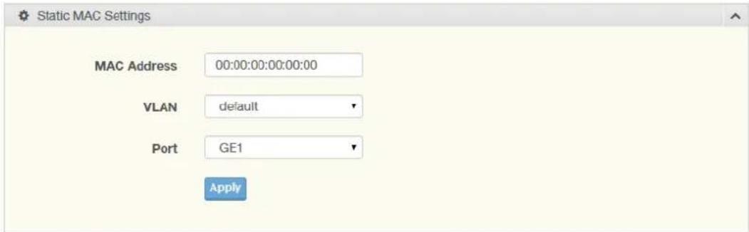
Figure 4.99 MAC Address Table > Static MAC
The following table describes the items in the previous figure.
Item Description
| MAC Address Enter the MAC address to which packets are statically forwarded. | |
| VLAN | Click the drop-down menu to select the VLAN ID number of the VLAN for which the MAC address is residing. |
| Port | Click the drop-down menu to select the port number. |
| Apply | Click Apply to save the values and update the screen. |
To access this page, click MAC Address Table > Static MAC Status.
The following figure displays the Static MAC Status settings.
| No. | MAC Address | VLAN | Port | Delete |
| 1 | C4:00 AD:F2:12:C8 | default(1) | CPU |
Figure 4.100 MAC Address Table > Static MAC Status
4.6.2 MAC Aging Time
The MAC Aging Time page allows you to set the MAC address of the aging time to study.
To access this page, click MAC Address Table > MAC Aging Time.
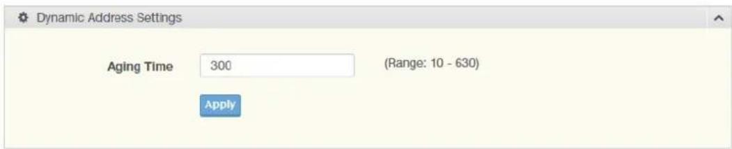
Figure 4.101 MAC Address Table > MAC Aging Time
The following table describes the items in the previous figure.
Item Description
Aging Time Enter the variable (10 to 630) to define the time required for aging.
Apply Click Apply to save the values and update the screen.
The ensuing table for Dynamic Address Status settings are informational only: Aging time.
4.6.3 Dynamic Forwarding Table
The Dynamic Forwarding function allows you to configure an address tables, which contain the following:
■ The port each hardware address is associated with
■ The VLAN to show or clear dynamic MAC entries
■ The MAC address selection
To access this page, click MAC Address Table > Dynamic Forwarding Table.
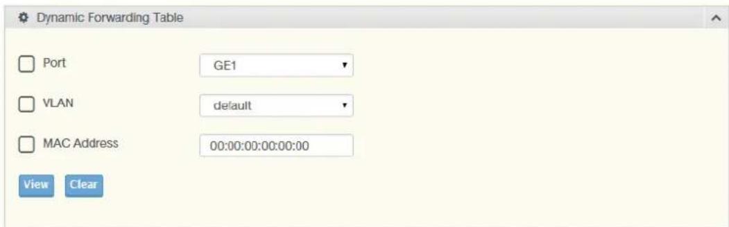
Figure 4.102 MAC Address Table > Dynamic Forwarding Table
The following table describes the items in the previous figure.
| Item Description | |
| Port | Click the drop-down menu to select the port number to show or clear dynamic MAC entries. If a port, VLAN or MAC address is not selected the whole dynamic MAC table is displayed or cleared. |
| VLAN | Click the drop-down menu to select the VLAN to show or clear dynamic MAC entries. |
| MAC Address | Enter the MAC address to show or clear dynamic MAC entries. If a port, VLAN or MAC address is not selected the whole dynamic MAC table is displayed or cleared. |
| View | Click View to display the MAC address information. |
| Clear | Click Clear to clear the MAC Address Information table. |
To access this page, click MAC Address Table > MAC Address Information.
The following figure displays the MAC Address Information settings.

Figure 4.103 MAC Address Table > MAC Address Information
4.7 Security
The Security function allows for the configuration of Storm Control, Port Security, Protected Ports, DoS Prevention, Applications, 802.1x, and IP Security.
4.7.1 Storm Control
The Storm Control page allows you to setup the units and Preamble/IFG to manage the occurrence of packet flooding on the LAN and consequent traffic to prevent the degrading of network performance.
4.7.1.1 Global Settings
To access this page, click Security > Storm Control > Global Settings.
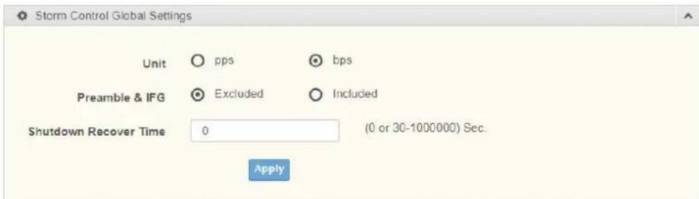
Figure 4.104 Security > Storm Control > Global Settings
The following table describes the items in the previous figure.
| Item Description | |
| Unit | Select pps or bps control units for the Storm Control function. |
| Preamble & IFG | Select Excluded or Included to setup the Storm Control Global settings.Excluded: exclude preamble & IFG (20 bytes) when count ingress storm control rate.Included: include preamble & IFG (20 bytes) when count ingress storm control rate. |
| Shutdown Recover Time | Enter the shutdown recover time in seconds with range 0 or 30 ~ 10000000. |
| Apply Click Apply to save the values and update the screen. | |
To access this page, click Security > Storm Control > Storm Control Global Information.
The following figure displays the Storm Control Global Information settings.
| Information Name | Information Value |
| Unit | bps |
| Preamble & IFG | Excluded |
| Shutdown Recover Time | 0 |
Figure 4.105 Security > Storm Control > Storm Control Global Information
4.7.1.2 Port Settings
The Port Settings page allows you to configure the port and the type of storm control association along with the value of the storm rate for the selected port.
To access this page, click Security > Storm Control > Port Settings.
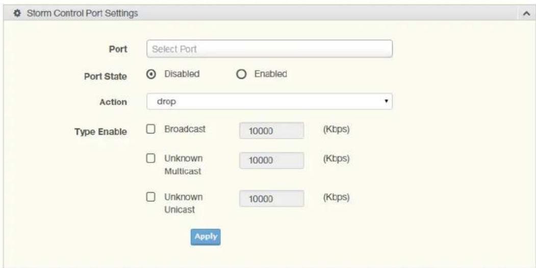
Figure 4.106 Security > Storm Control > Port Settings
The following table describes the items in the previous figure.
Item Description
Port Enter the port number to designate the local port for the Storm Control function.
Port State Select Disabled or Enabled to define the port state
Action Click the drop-down menu to select the type of action to designate for the selected port during a Storm Control incident. The options are Drop and Shutdown.
Type Enable Click the radio button to enable Broadcast, Unknown Multicast, or Unknown Unicast.
■ Broadcast: Select the variable in Kbps to define the broadcast bandwidth.
Unknown Multicast: Select the variable in Kbps to define the unknown multicast setting.
Unknown Unicast: Select the variable in Kbps to define the unknown unicast setting.
Apply Click Apply to save the values and update the screen.
The ensuing table for Storm Control Port Information settings are informational only: Port, Port State, Broadcast (Kbps), Unknown Multicast (Kbps), Unknown Unicast (Kbps) and Action.
The following figure displays the Storm Control Port Information settings.
| Port | Port State | Broadcast (Kbps) | Unknown Multicast (Kbps) | Unknown Unicast (Kbps) | Action |
| GE1 | Disabled | Off (10000) | Off (10000) | Off (10000) | Drop |
| GE2 | Disabled | Off (10000) | Off (10000) | Off (10000) | Drop |
| GE3 | Disabled | Off (10000) | Off (10000) | Off (10000) | Drop |
| GE4 | Disabled | Off (10000) | Off (10000) | Off (10000) | Drop |
| GE5 | Disabled | Off (10000) | Off (10000) | Off (10000) | Drop |
Figure 4.107 Security > Storm Control > Storm Control Port Information
4.7.2 Port Security
The Port Security page allows you to configure port isolation behavior.
To access this page, click Security > Port Security.
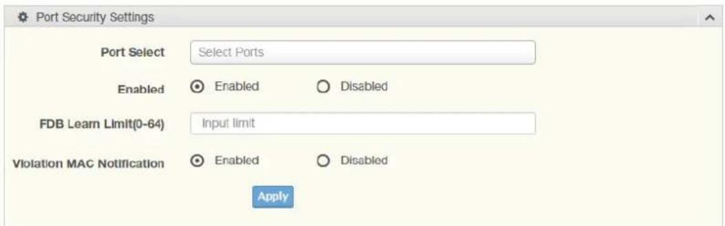
Figure 4.108 Security > Port Security
The following table describes the items in the previous figure.
| Item Description | |
| Port Select Enter a single or multiple port numbers to configure. | |
| Enabled Select Enabled or Disabled to define the selected Port. | |
| FDB Learn Limit (0-64) | Enter the variable (0 to 64) to set the learn limit for the FDB setting. |
| Violation MAC Notifi-cation | Select Enabled or Disabled to define the selected Port. |
| Apply Click Apply to save the values and update the screen. | |
The ensuing table for Port Security Information settings are informational only: Port, Enabled, FDB Learn Limit and Violation MAC Notification.
4.7.3 Protected Ports
The Protected Port page allows you to configure a single or multiple ports as a protected or unprotected type.
To access this page, click Security > Protected Ports.
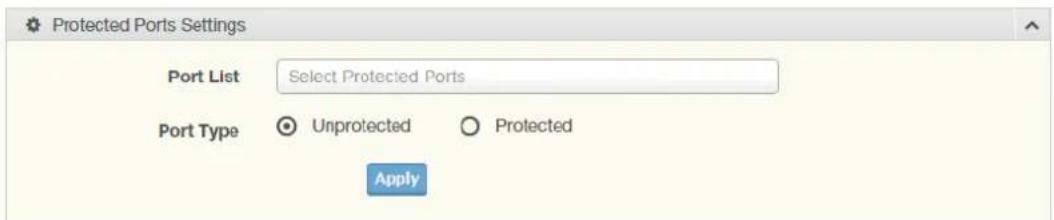
Figure 4.109 Security > Protected Ports
The following table describes the items in the previous figure.
| Item Description |
| Port List Enter the port number to designate for the Protected Port setting. |
| Port Type Select Unprotected or Protected to define the port type. |
| Apply Click Apply to save the values and update the screen. |
The ensuing table for Protected Ports Status settings are informational only: Protected Ports and Unprotected Ports.
4.7.4 DoS Prevention
The DoS Prevention page allows you to setup (enabled or disabled) the denial of service.
4.7.4.1 DoS Global Settings
The DoS Global Settings page allows you to configure (enabled or disabled) the setting for each function.
To access this page, click Security > DoS Prevention > DoS Global Settings.
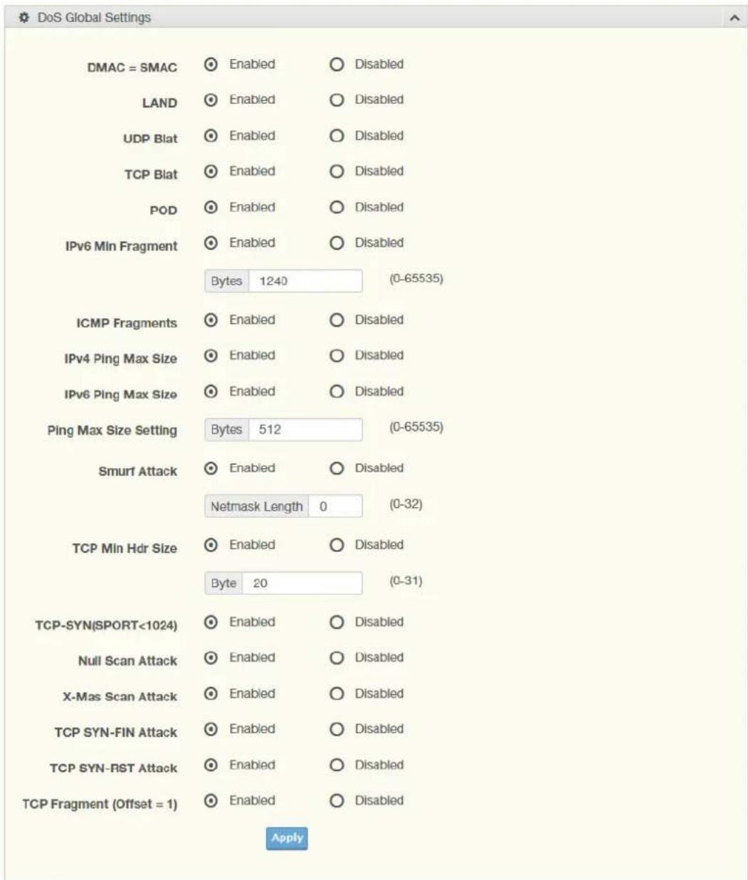
Figure 4.110 Security > DoS Prevention > DoS Global Settings
The following table describes the items in the previous figure.
| Item Description | |
| DMAC = SMAC | Click Enabled or Disabled to define DMAC-SMAC for the DoS Global settings. |
| LAND | Click Enabled or Disabled to define LAND for the DoS Global settings. |
| UDP Blat | Click Enabled or Disabled to define UDP Blat for the DoS Global settings. |
| TCP Blat | Click Enabled or Disabled to define TCP Blat for the DoS Global settings. |
| POD | Click Enabled or Disabled to define POD for the DoS Global settings. |
| IPv6 Min Fragment | Click Enabled or Disabled to define minimum fragment size for the IPv6 protocol.Enter the variable in bytes (0 to 65535) to set the minimum fragment size when the function is enabled. |
| ICMP Fragments | Click Enabled or Disabled to define the ICMP Fragments function. |
| IPv4 Ping Max Size | Click Enabled or Disabled to set the maximum ping size for the IPv4 protocol. |
| IPv6 Ping Max Size | Click Enabled or Disabled to set a maximum ping size for the IPv6 protocol. |
| Ping Max Size Setting | Enter the variable in bytes (0 to 65535) to set the maximum ping size. |
| Smurf Attack | Click Enabled or Disabled to set the Smurf Attack function. |
| TCP Min Hdr Size | Click Enabled or Disabled to set the minimum header size.Enter the variable in bytes (0 to 31) to set the minimum header size. |
| TCP-SYN (SPORT < 1024) | Click Enabled or Disabled to set the TCP synchronization function (sport < 1021). |
| Null Scan Attack | Click Enabled or Disabled to set the Null Scan Attack function. |
| X-Mas Scan Attack | Click Enabled or Disabled to set the X-Mas Scan function. |
| TCP SYN-FIN Attack | Click Enabled or Disabled to set the TCP synchronization termination attack function. |
| TCP SYN-RST Attack | Click Enabled or Disabled to set the TCP synchronization reset attack function. |
| TCP Fragment (Offset = 1) | Click Enabled or Disabled to set the TCP fragment function (offset =1). |
| Apply Click Apply to save the values and update the screen. | |
To access this page, click Security > DoS Prevention > DoS Global Information. The following figure displays the DoS Global Information settings.
| DoS-Global Information | |
| Information Name | Information Value |
| DMAC = SMAC | Enabled |
| Land Attack | Enabled |
| UDP Blat | Enabled |
| TCP Blat | Enabled |
| POD (Ping of Death) | Enabled |
| IPv6 Min Fragment Size | Enabled (1240 Bytes) |
| ICMP Fragment Packets | Enabled |
| IPv4 Ping Max Packet Size | Enabled (512 Bytes) |
| IPv6 Ping Max Packet Size | Enabled (512 Bytes) |
| Smurf Attack | Enabled (Netmask Length: 0) |
| TCP Min Header Length | Enabled (20 Bytes) |
| TCP Syn (SPORT < 1024) | Enabled |
| Null Scan Attack | Enabled |
| X-Mas Scan Attack | Enabled |
Figure 4.111 Security > Storm Control > DoS Global Information
4.7.4.2 DoS Port Settings
The DoS Port Settings page allow you to configure DoS security (enabled or disabled) for the selected port.
To access this page, click Security > DoS Prevention > DoS Port Settings.
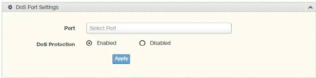
Figure 4.112 Security > DoS Prevention > DoS Port Settings
The following table describes the items in the previous figure.
| Item Description | |
| Port Select the port to configure for the DoS prevention function. | |
| DoS Protection Click Enabled or Disabled to set the DoS Port security function state. | |
| Apply Click Apply to save the values and update the screen. | |
| The ensuing table for DoS Port Status settings are informational only: Port and DoS Protection. |
4.7.5 Applications
The Applications function allows you to configure various types of AAA lists.
4.7.5.1 TELNET
The TELNET page allows you to combine all kinds of AAA lists with the Telnet line. To access this page, click Security > Applications > TELNET.

Figure 4.113 Security > Applications > TELNET
The following table describes the items in the previous figure.
| Item Description | |
| Telnet Service | Click Enabled or Disabled to set remote access through the Telnet Service function. |
| Apply Click Apply to save the values and update the screen. | |
| Disconnect Click Disconnect to disable the current Telnet service. | |
The ensuing table for Telnet Information settings are informational only: Telnet Service and Current Telnet Sessions Count.
4.7.5.2 SSH
Secure Shell (SSH) is a protocol providing secure (encrypted) management connection to a remote device.
To access this page, click Security > Applications > SSH.

Figure 4.114 Security > Applications > SSH
The following table describes the items in the previous figure.
| Item Description | |
| SSH Service | Click Enabled or Disabled to set up Ethernet encapsulation (remote access) through the Secure Shell (SSH) function. |
| Apply Click Apply to save the values and update the screen. | |
The ensuing table for SSH Information settings are informational only: SSH.
4.7.5.3 HTTP
The HTTP page allows you to combine all kinds of AAA lists to the HTTP line. Attempts to access the switch's Web UI from HTTP are first authenticated.
To access this page, click Security > Applications > HTTP.
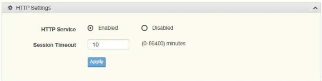
Figure 4.115 Security > Applications > HTTP
The following table describes the items in the previous figure.
| Item Description | |
| HTTP Service | Click Enabled or Disabled to set up Ethernet encapsulation (remote access) through HTTP function. |
| Session Timeout | Enter the variable in minutes (0 to 86400) to define the timeout period for the HTTP session. |
| Apply Click Apply to save the values and update the screen. | |
The ensuing table for HTTP Information settings are informational only: HTTP Service and Session Timeout.
4.7.5.4 HTTPS
The HTTPS page allows you to combine all kinds of AAA lists on the HTTPS line. Attempts to access the switch's Web UI from HTTPS are first authenticated.
To access this page, click Security > Applications > HTTPS.
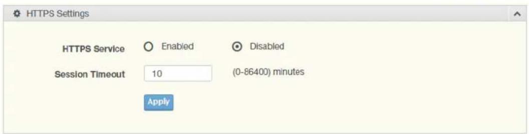
Figure 4.116 Security > Applications > HTTPS
The following table describes the items in the previous figure.
| Item Description | |
| HTTPS Service | Click Enabled or Disabled to set up Ethernet encapsulation over HTTPS. |
| Session Timeout | Enter the variable in minutes (0 to 86400) to define the timeout period for the HTTP session. |
| Apply | Click Apply to save the values and update the screen. |
The ensuing table for HTTPS Information settings are informational only: HTTPS Service and Session Timeout.
4.7.6 802.1x
The 802.1x function provides port-based authentication to prevent unauthorized devices (clients) from gaining access to the network.
4.7.6.1 802.1x Global Settings
The 802.1x Global Settings page allows you to set the state (enabled or disabled) for the selected IP server address, port, accounting port and associated password, including a reauthentication period.
To access this page, click Security > 802.1x > 802.1x Global Settings.
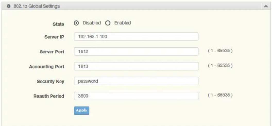
Figure 4.117 Security > 802.1x > 802.1x Global Settings
The following table describes the items in the previous figure.
| Item Description | |
| State | Click Enabled or Disabled to set up 802.1x Setting function. |
| Server IP | Enter the IP address of the local server providing authentication func-tion. |
Item Description
Server Port Enter the port number (1 to 65535) assigned to the listed Server IP.
Accounting Port Enter the port number (1 to 65535) assigned to the listed server IP configured to provide authorization and authentication for network access.
Security Key Enter the variable to define the network security key used in authentication.
Reauth Period Enter the variable in seconds to define the period of time between authentication attempts.
Apply Click Apply to save the values and update the screen.
To access this page, click Security > 802.1x > 802.1x Information.
The following figure displays the 802.1x Information settings.
| Information Name | Information Value |
| 802 1xState | Disabled |
| Server IP | 192.168.1 100 |
| Server Port | 1812 |
| Accounting Port | 1913 |
| Security Key | password |
| Reauth Period | 3600 |
Figure 4.118 Security > 802.1x > 802.1x Information
4.7.6.2 802.1x Port Configuration
The 802.1x Port Configuration page allows you to identify the authorization state for a port by using a MAC or Port authentication base.
To access this page, click Security > 802.1x > 802.1x Port Configuration.
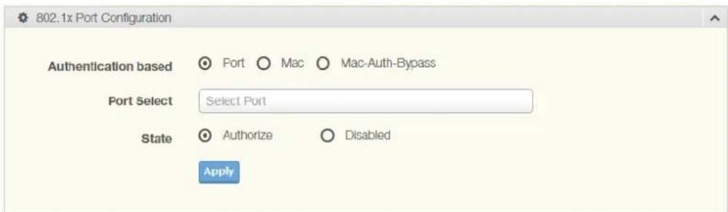
Figure 4.119 Security > 802.1x > 802.1x Port Configuration
The following table describes the items in the previous figure.
Item Description
Authentication based Click Port, Mac or Mac-Auth-Bypass to designate the type of configuration for the 802.1x Port setting.
Port Select Enter the port number associated with the configuration setting.
State Click Authorize or Disabled to define the listed port's state mode.
Apply Click Apply to save the values and update the screen.
The ensuing table for 802.1x Port Authorization settings are informational only: Port and Port State.
4.7.7 IP Security
This section provides you a means to configure the IP Security settings.
4.7.7.1 Global Settings
The Global Settings page allows you to set the IP Security status (enabled or disabled).
To access this page, click Security > IP Security > Global Settings.
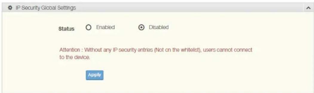
Figure 4.120 Security > IP Security > Global Settings
The following table describes the items in the previous figure.
| Item Description | |
| Status | Click Enabled or Disabled to define the global setting for the IP security function. |
| Apply Click Apply to save the values and update the screen. | |
The ensuing table for IP Security Status settings are informational only: IP Security.
4.7.7.2 Entry Settings
Once the Global Setting is enabled, use the Entry Settings to define an IP Security entry.
To access this page, click Security > IP Security > Entry Settings.
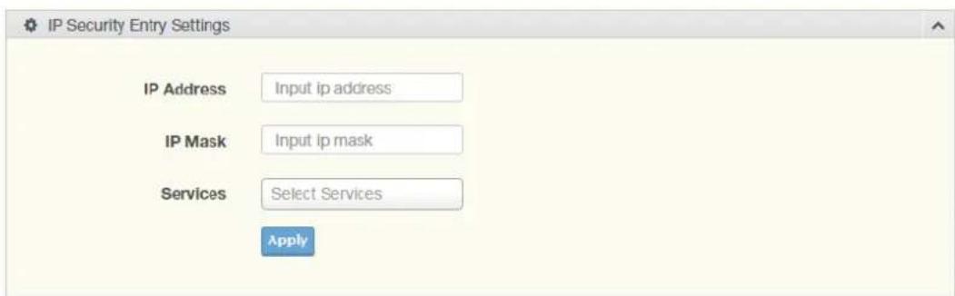
Figure 4.121 Security > IP Security > Entry Settings
The following table describes the items in the previous figure.
| Item Description | |
| IP Address Enter the source IP address to apply the IP Security function. | |
| IP Mask Enter the IP address for use in masking the previous IP Address. | |
| Services | Enter the type of services to associate with the entry setting. |
| Apply Click Apply to save the values and update the screen. | |
The ensuing table for IP Security Entry Information settings are informational only: IP Address, IP Mask, Services and Action.
4.7.8 Security Login
4.7.8.1 Global Settings
This function provides a means to enable or disable the global security settings for the system.
To access this page, click Security > Security Login > Global Settings.

Figure 4.122 Security > Security Login > Global Settings > Global Settings The following table describes the items in the previous figure.
| Item Description | |
| State | Click Enabled or Disabled to set up security login global setting status. |
Apply Click Apply to save the values and update the screen.
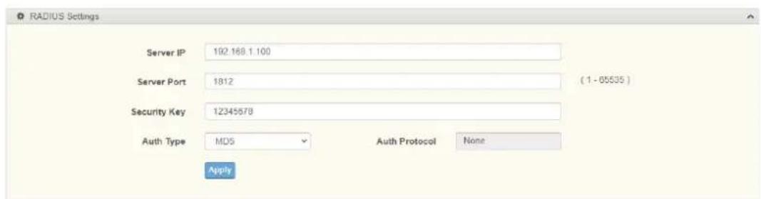
Figure 4.123 Security > Security Login > Global Settings > RADIUS Settings The following table describes the items in the previous figure.
| Item Description |
| Server IP Enter the IP address of the local server providing authentication function. |
| Server Port Enter the port number (1 to 65535) assigned to the listed Server IP. |
| Security Key Enter the variable to define the network security key used in authentication. |
| Auth Type Click the drop down menu to select the Authentication type with option MD5, TTLS or PEAP. Each authentication type is mapping to specified authentication protocol as below:MD5: Using authentication protocol with None.TTLS: Using authentication protocol with TTLS.PEAP: Using authentication protocol with PEAP. |
Apply Click Apply to save the values and update the screen.
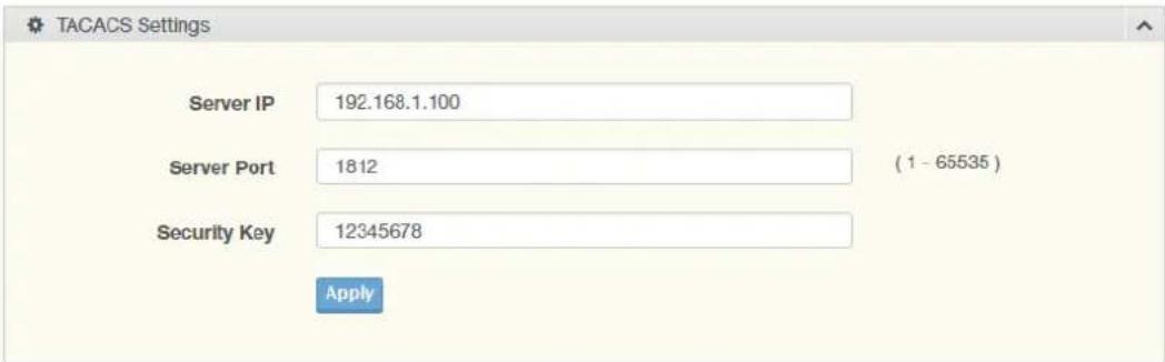
Figure 4.124 Security > Security Login > Global Settings > TACACS Settings The following table describes the items in the previous figure.
| Item Description | |
| Server IP Enter the IP address of the local server providing authentication function. | |
| Server Port Enter the port number (1 to 65535) assigned to the listed Server IP. | |
| Security Key Enter the variable to define the network security key used in authentication. | |
| Apply | Click Apply to save the values and update the screen. |
To access this page, click Security > Security Login > Global Settings > Global Information.
The following figure displays the Global Information settings.
| Information Name | Information Value |
| State | Disabled |
| RADIUS Configuration | Information Value |
| Server IP | 192.168 1.100 |
| Server Port | 1812 |
| Security Key | 12345678 |
| Auth Type | MD5 |
| Auth Protocol | None |
| TACACS Configuration | Information Value |
| Server IP | 192.168 1.100 |
| Server Port | 1812 |
| Security Key | 12345678 |
Figure 4.125 Security > Security Login > Global Settings > Global Information
4.7.8.2 Access Control Settings
This function specifies the login authentication type for the system.
To access this page, click Security > Security Login > Security Login Access Control Settings.
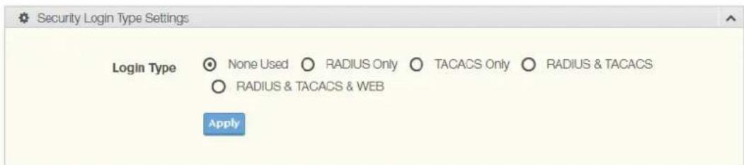
Figure 4.126 Security > Security Login > Access Control Settings > Security Login Type Settings
The following table describes the items in the previous figure.
Item Description
Login Type Click to select the login type. Options include: None Used, RADIUS Only, TACACS Only, RADIUS & TACACS or RADIUS & TACACS & WEB.
Apply Click Apply to save the values and update the screen.
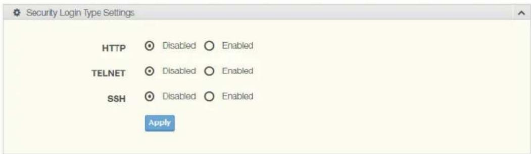
Figure 4.127 Security > Security Login > Access Control Settings > Security Login Type Settings
The following table describes the items in the previous figure.
Item Description
HTTP Click Enabled or Disabled to set up HTTP.
TELNET Click Enabled or Disabled to set up HTTPS.
SSH Click Enabled or Disabled to set up SSH.
Apply Click Apply to save the values and update the screen.
To access this page, click Security > Security Login > Access Control Settings > Global Information.
The following figure displays the Access Control Information settings.
| Information Name | Information Value |
| Login Type | None Used |
| HTTP | Disabled |
| TELNET | Disabled |
| SSH | Disabled |
Figure 4.128 Security > Security Login > Access Control Settings > Access Control Information
4.7.9 Access Control List
The Access Control List is the basic traffic filter for ingress and egress packets. Allow user to filter criteria for diverse protocols and deny access to specific source or destination IP/MAC addresses.
4.7.9.1 MAC ACL
Entry Settings
To access this page, click Security > Access Control List > MAC ACL > Entry Settings.
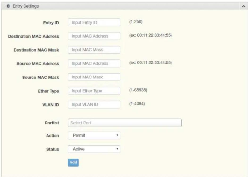
Figure 4.129 Security > Access Control List > MAC ACL > Entry Settings
The following table describes the items in the previous figure.
| Item Description | |
| Entry ID Type in the value designating the entry ID. | |
| Destination MAC Address | Enter the MAC address to set destination MAC address. |
| Destination MAC Mask | Enter a value to specify the subnet mask for the destination MAC address. |
| Source MAC Address | Enter the MAC address to set source MAC address. |
| Source MAC Mask Enter a value to specify the subnet mask for the source MAC address. | |
| Ether Type Enter a value to specify the DNS server for the interface. | |
| VLAN ID Type in the value designating the VLAN ID. | |
| Portlist Select the port to configure for the MAC ACL function. | |
| Action Click the drop down menu to select the MAC ACL action. Options include: Permit, Drop, Assign Queue, Redirect Port or Redirect Port-list. | |
| Assign Queue Click the drop down menu to select the queue. The function is only available when Action is Assign Queue. | |
| Status Click the drop down menu to select the MAC ACL status. Options include: Active or Inactive. | |
| Add Click Add to add a MAC ACL entry. | |
Entry List
To access this page, click Security > Access Control List > MAC ACL > Entry List. The following figure displays the Entry List settings.

Figure 4.130 Security > Access Control List > MAC ACL > Entry List
4.7.9.2 IP ACL
Entry Settings
To access this page, click Security > Access Control List > IP ACL > Entry Settings.
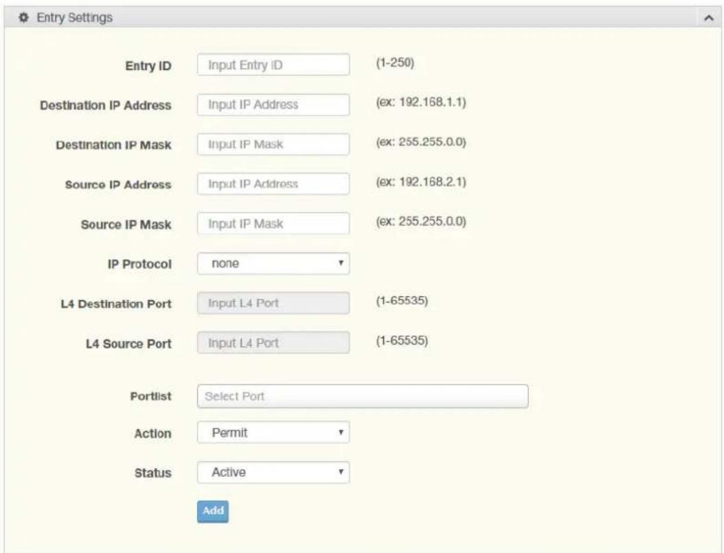
Figure 4.131 Security > Access Control List > IP ACL > Entry Settings
The following table describes the items in the previous figure.
| Item Description | |
| Entry ID Type in the value designating the entry ID. | |
| Destination IP Address | Enter the IP address to set destination IP address. |
| Destination IP Mask | Enter a value to specify the subnet mask for the destination IP address. |
| Source IP Address | Enter the IP address to set source IP address. |
| Source IP Mask | Enter a value to specify the subnet mask for the source IP address. |
| IP Protocol | Click the drop down menu to select the IP protocol. Options include: none, ICMP, TCP or UDP. |
| L4 Destination Port | Enter a value to specify the L4 destination port. |
| L4 Source Port | Enter a value to specify the L4 source port. |
| Item | Description |
| Portlist Select the port to configure for the IP ACL function. | |
| Action Click the drop down menu to select the IP ACL action. Options include: Permit, Drop or Assign Queue. | |
| Assign Queue Click the drop down menu to select the queue. The function is only available when Action is Assign Queue. | |
| Status | Click the drop down menu to select the IP ACL status. Options include: Active or Inactive. |
| Add | Click Add to add an IP ACL entry. |
Entry List
To access the Entry List, click Security > Access Control List > IP ACL > Entry List.
The ensuing figure for IP ACL Information settings are informational only: Entry ID, Summary, Portlist, Action, Status and Modify (Click Edit to edit the desire entry id or Delete to remove the desired entry id).
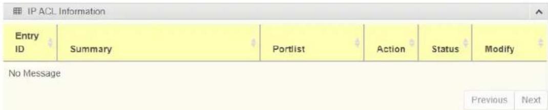
Figure 4.132 Security > Access Control List > IP ACL > Entry List
4.7.10 IP Source Guard
4.7.10.1 Global Settings
To access this page, click Security > IP Source Guard > Global Settings.
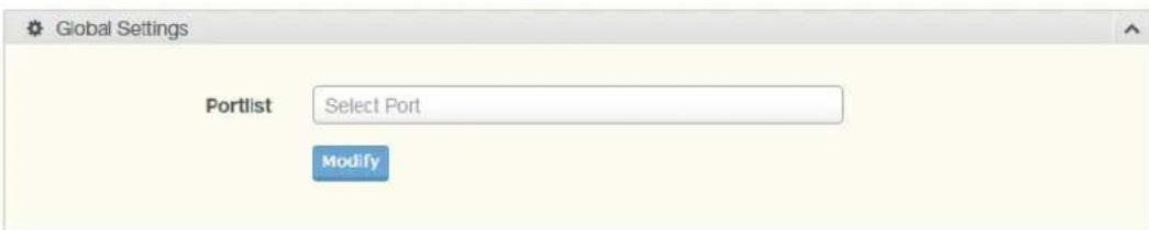
Figure 4.133 Security > IP Source Guard > Global Settings
The following table describes the items in the previous figure.
| Item | Description |
| Portlist Select the port to verify. | |
| Modify | Click Modify to save the values and update the screen. |
The following figure displays the Global Information settings.
| Information Name | Information Value |
| State | Disabled |
| RADIUS Configuration | Information Value |
| Server IP | 192.168.1.100 |
| Server Port | 1812 |
| Security Key | 12345678 |
| Auth Type | MD5 |
| Auth Protocol | None |
| TACACS Configuration | Information Value |
| Server IP | 192 168.1.100 |
| Server Port | 1812 |
| Security Key | 12345678 |
Figure 4.134 Security > IP Source Guard > Global Information
4.7.10.2 Entry Settings
To access this page, click Security > IP Source Guard > Entry Settings.
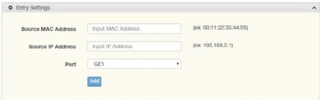
Figure 4.135 Security > IP Source Guard > Entry Settings
The following table describes the items in the previous figure.
| Item Description | |
| Source MAC Address | Enter the MAC address to set source MAC address. |
| Source IP Address | Enter the IP address to set source IP address. |
| Port Select the port to configure for the IP source guard. | |
| Add Click Add to add an IP source guard. | |
To access this page, click Security > IP Source Guard > Entry Information. The following figure displays the Entry Information settings.

Figure 4.136 Security > IP Source Guard > Entry Information
4.7.11 DHCP Snooping
4.7.11.1 Global Settings
To access this page, click Security > DHCP Snooping > Global Settings.

Figure 4.137 Security > DHCP Snooping > Global Settings > DHCP Snooping State Settings
The following table describes the items in the previous figure.
Item Description
DHCP Snooping Click Enabled or Disabled to set DHCP snooping state. State
Apply Click Apply to save the values and update the screen.
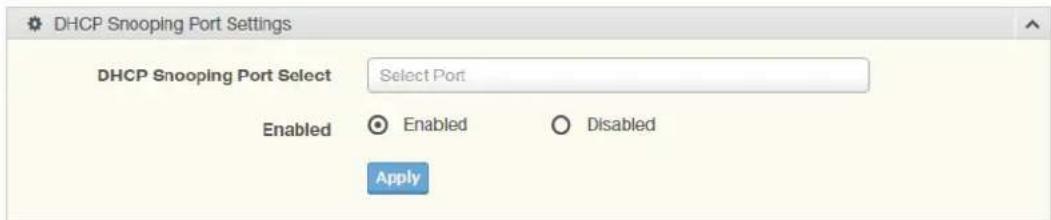
Figure 4.138 Security > DHCP Snooping > Global Settings > DHCP Snooping Port Settings
The following table describes the items in the previous figure.
Item Description
DHCP Snooping Port Select the port to configure for the DHCP Snooping port. Select
Enabled Click Enabled or Disabled to enable DHCP Snooping port.
Apply Click Apply to save the values and update the screen.
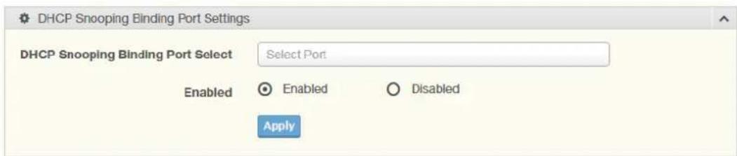
Figure 4.139 Security > DHCP Snooping > Global Settings > DHCP Snooping Binding Port Settings
The following table describes the items in the previous figure.
Item Description
DHCP Snooping Select the port to configure for the DHCP snooping binding port. Binding Port Select
Enabled Click Enabled or Disabled to enable DHCP Snooping binding.
Apply Click Apply to save the values and update the screen.
To access this page, click Security > DHCP Snooping > Global Settings > DHCP Snooping Information.
The following figure displays the DHCP Snooping Information settings.
| DHCP Snooping Information | |
| Information Name | Information Value |
| DHCP Snooping | Disabled |
| DHCP Snooping Port | None |
| DHCP Snooping Binding Port | None |
Figure 4.140 Security > DHCP Snooping > Global Settings > DHCP Snooping Information
4.7.11.2 Entry Settings
To access this page, click Security > DHCP Snooping > Entry Settings. The following figure displays the IP Security Entry Information settings.

Figure 4.141 Security > DHCP Snooping > Entry Settings > Entry Information
To access this page, click Security > DHCP Snooping > L2-Relay Settings. The following figure displays the L2-Relay State settings.

Figure 4.142 Security > DHCP Snooping > L2-Relay Settings
The following table describes the items in the previous figure.
Item Description
L2-Relay State Click Enable or Disable to set the function state.
Apply Click Apply to save the values and update the screen.
To access this page, click Security > DHCP Snooping > L2-Relay Port Settings. The following figure displays the L2-Relay Port settings.

Figure 4.143 Security > DHCP Snooping > L2-Relay Port Settings
The following table describes the items in the previous figure.
Item Description
L2-Relay Port Select Enter the port number to add the corresponding port to the relay.
Enabled Click Enable or Disable to set the function state.
Apply Click Apply to save the values and update the screen.
To access this page, click Security > DHCP Snooping > L2-Relay VLAN Settings.
The following figure displays the L2-Relay VLAN settings.

Figure 4.144 Security > DHCP Snooping > L2-Relay VLAN Settings
The following table describes the items in the previous figure.
Item Description
L2-Relay VLAN List Enter the port number to add the corresponding port to the relay.
Enabled Click Enable or Disable to set the function state.
Apply Click Apply to save the values and update the screen.
To access this page, click Security > DHCP Snooping > Circuit ID Settings.
The following figure displays the Circuit ID Settings & Remote ID settings.
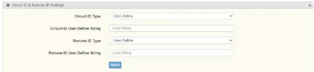
Figure 4.145 Security > DHCP Snooping > Circuit ID Settings
The following table describes the items in the previous figure.
Item Description
Circuit ID Type Enter the port number to add the corresponding port to the relay.
Circuit-ID User-Define String Click Enable or Disable to set the function state.
Remote ID Type
Remote-ID User-Define String
Apply Click Apply to save the values and update the screen.
To access this page, click Security > DHCP Snooping > L2 Relay Information. The following figure displays the L2 Relay Information settings.
| Information Name | Information Value |
| L2-Relay State | Disabled |
| L2-Relay Enable Port | |
| L2-Relay Enable VLAN | |
| L2-Relay Circuit-ID Type | User-Define |
| L2-Relay Circuit-ID User-Define String | |
| L2-Relay Remote-ID Type | User-Define |
| L2-Relay Remote-ID User-Define String |
Figure 4.146 Security > DHCP Snooping > L2 Relay Information
The following table describes the items in the previous figure.
4.7.12 ARP Spoofing
To access this page, click Security > ARP Spoofing.
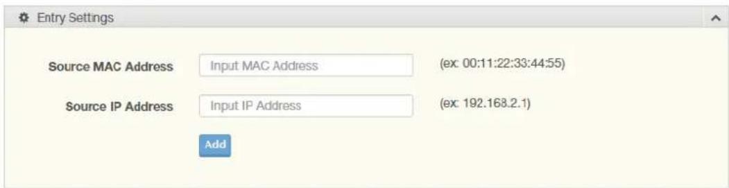
Figure 4.147 Security > ARP Spoofing
The following table describes the items in the previous figure.
Item Description
Source MAC Enter the MAC address to set source MAC address.
Address
Source IP Address Enter the IP address to set source IP address.
Add Click Add to add an ARP spoofing.
To access this page, click Security > Entry Information.
The following figure displays the Entry Information settings.

Figure 4.148 Security > Entry Information
The following table describes the items in the previous figure.
4.8 QoS
The QoS function allows you to configure settings for the switch QoS interface and how the switch connects to a remote server to get services.
4.8.1 General
Traditionally, networks operate on a best-effort delivery basis, all traffic has equal priority and an equal chance of being delivered in a timely manner. When there is congestion, all traffic has an equal chance of being dropped.
The QoS feature can be configured for congestion-management and congestion-avoidance to specifically manage the priority of the traffic delivery. Implementing QoS in the network makes performance predictable and bandwidth utilization much more effective.
The QoS implementation is based on the prioritization values in Layer 2 frames.
4.8.1.1 QoS Properties
The QoS Properties allows you to set the QoS mode.
To access this page, click QoS > General > QoS Properties.

Figure 4.149 QoS > General > QoS Properties
The following table describes the items in the previous figure.
Item Description
QoS Mode Select Disabled or Basic to setup the QoS function.
Apply Click Apply to save the values and update the screen.
The ensuing table for QoS Global Information settings are informational only: QoS Mode.
4.8.1.2 QoS Settings
Once the QoS function is enabled, you can configure the available settings.
To access this page, click QoS > General > QoS Settings.
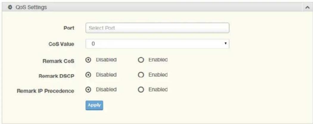
Figure 4.150 QoS > General > QoS Settings
The following table describes the items in the previous figure.
| Item | Description |
| Port | Enter the port number to associate with the QoS setting. |
| CoS Value | Click the drop-down menu to designate the Class of Service (CoS) value (0 to 7) for the Port entry. |
| Remark CoS | Click Disabled or Enabled to setup the Remark CoS function. When enabled the LAN (preassigned priority values) is marked at Layer 2 boundary to CoS values. |
| Remark DSCP | Click Disabled or Enabled to setup the DSCP remark option for the QoS function. |
| Remark IP Precedence | Click Disabled or Enabled to setup the Remark IP Precedence for the QoS function. |
| Apply | Click Apply to save the values and update the screen. |
To access this page, click QoS > General > QoS Status.
The following figure displays the QoS Status settings.
| Port | CoS Value | Remark CoS | Remark DSCP | Remark IP Precedence |
| GE1 | 0 | Disabled | Disabled | Disabled |
| GE2 | 0 | Disabled | Disabled | Disabled |
| GE3 | 0 | Disabled | Disabled | Disabled |
| GE4 | 0 | Disabled | Disabled | Disabled |
| GE5 | 0 | Disabled | Disabled | Disabled |
| GE6 | 0 | Disabled | Disabled | Disabled |
| GE7 | 0 | Disabled | Disabled | Disabled |
| GE8 | 0 | Disabled | Disabled | Disabled |
Figure 4.151 QoS > General > QoS Status
4.8.1.3 Queue Scheduling
The switch support eight CoS queues for each egress port. For each of the eight queues, two types of scheduling can be configured: Strict Priority and Weighted Round Robin (WRR).
Strict Priority scheduling is based on the priority of queues. Packets in a high-priority queue are always sent first and packets in a low-priority queue are only sent after all the high priority queues are empty.
Weighted RoundRobin (WRR) scheduling is based on the user priority specification to indicate the importance (weight) of the queue relative to the other CoS queues. WRR scheduling prevents low-priority queues from being completely ignored during periods of high priority traffic. The WRR scheduler sends some packets from each queue in turn.
To access this page, click QoS > General > QoS Scheduling.
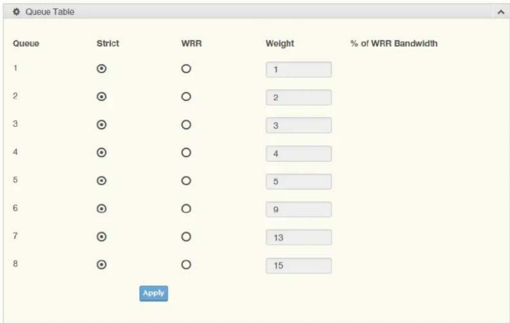
Figure 4.152 QoS > General > QoS Scheduling
The following table describes the items in the previous figure.
| Item Description | |
| Queue Queue entry for egress port. | |
| Strict Select Strict to assign the scheduling designation to the selected queue. | |
| WRR Select WRR to assign the scheduling designation to the selected queue. | |
| Weight Enter a queue priority (weight) relative to the defined entries (WRR only). | |
| % of WRR Bandwidth Displays the allotted bandwidth for the queue entry in percentage values. | |
| Apply Click Apply to save the values and update the screen. | |
| To access this page, click QoS > General > QoS Information. The following figure displays the Queue Information settings. | |
| Queue Information | |
| Information Name | Information Value |
| Strict Priority Queue Number | 8 |
Figure 4.153 QoS > General > QoS Information
4.8.1.4 CoS Mapping
The CoS Mapping allows you to apply CoS mapping.
To access this page, click QoS > General > CoS Mapping.
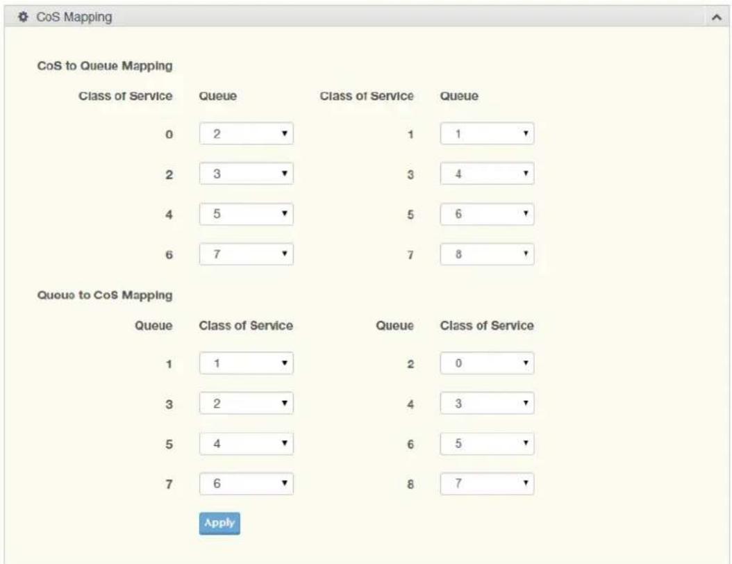
Figure 4.154 QoS > General > CoS Mapping
The following table describes the items in the previous figure.
| Item Description |
| CoS to Queue Mapping |
| Class of Service Displays the CoS for the queue entry. |
| Queue Click the drop-down menu to select the queue priority for selected CoS. |
| Queue to CoS Mapping |
| Queue Displays the queue entry for CoS mapping. |
| Class of Service Click the drop-down menu to select the CoS type |
| Apply Click Apply to save the values and update the screen. |
To access this page, click QoS > General > CoS Mapping.
The following figure displays the CoS Mapping Information settings.
| Information Name | Information Value |
| Strict Priority Queue Number | 8 |
Figure 4.155 QoS > General > CoS Mapping
To access this page, click QoS > General > CoS Mapping.
The following figure displays the Queue Mapping Information settings.
| Queue | Mapping to CoS |
| 1 | 1 |
| 2 | 0 |
| 3 | 2 |
| 4 | 3 |
| 5 | 4 |
| 6 | 5 |
Figure 4.156 QoS > General > CoS Mapping
4.8.1.5 DSCP Mapping
The DSCP to Queue mapping function maps queue values in incoming packets to a DSCP value that QoS uses internally to represent the priority of the traffic. The following table shows the DSCP to Queue map.
If these values are not appropriate for your network, you need to modify them.
To access this page, click QoS > General > DSCP Mapping.
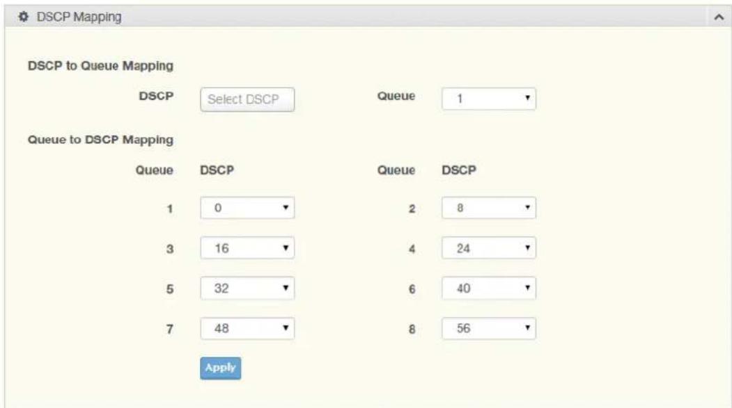
Figure 4.157 QoS > General > DSCP Mapping
The following table describes the items in the previous figure.
| Item Description |
| DSCP to Queue Mapping |
| DSCP Enter the DSCP entry to define the precedence values. |
| Queue Click the drop-down menu to select the queue designation for the DSCP value. |
| Queue to DSCP Mapping |
| Queue Displays the queue value for the DSCP map. |
| DSCP Enter the DSCP entry to define the precedence values. |
| Apply Click Apply to save the values and update the screen. |
The ensuing table for DSCP Mapping Information settings are informational only: DSCP and Mapping to Queue.
The ensuing table for Queue Mapping Information settings are informational only: Queue and Mapping to DSCP.
The IP Precedence Mapping allows you to set IP Precedence mapping.
To access this page, click QoS > General > IP Precedence Mapping.
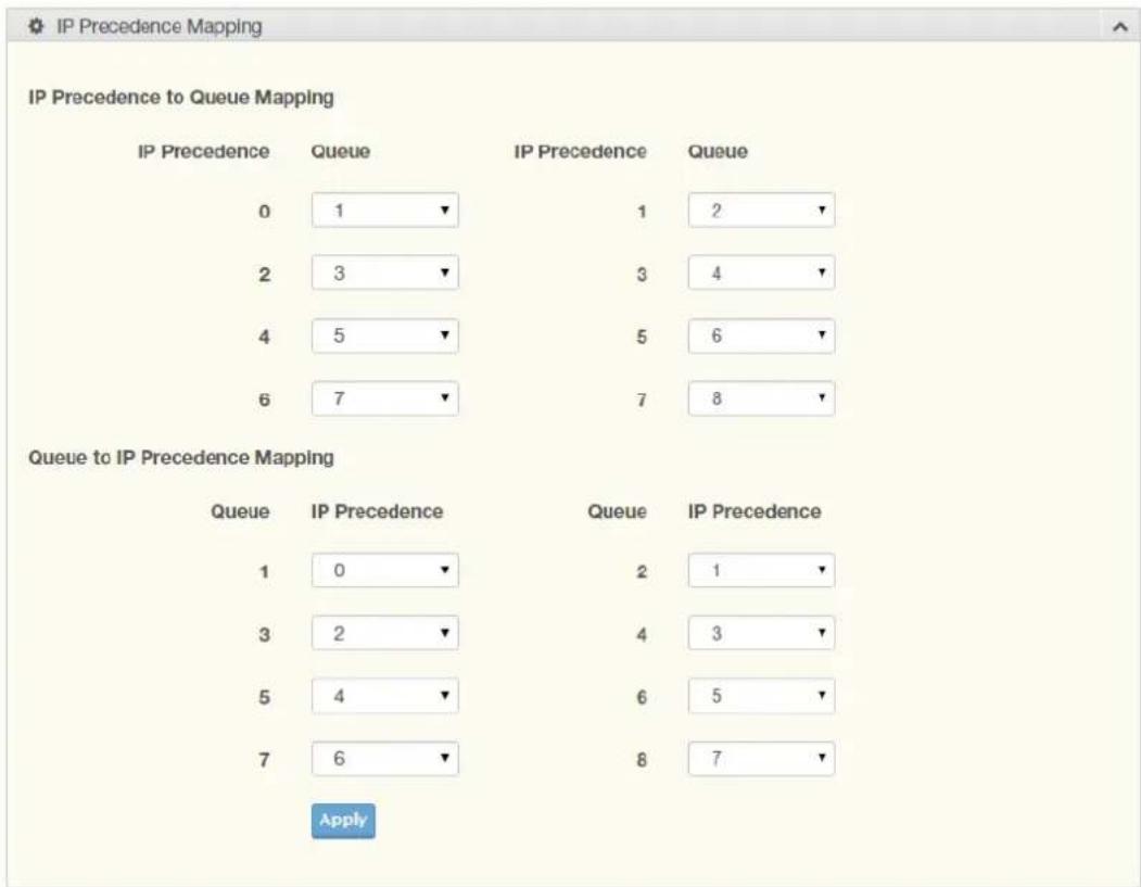
Figure 4.158 QoS > General > IP Precedence Mapping
The following table describes the items in the previous figure.
| Item Description | |
| IP Precedence to Queue Mapping | |
| IP Precedence Displays the IP precedence value for the queue map. | |
| Queue | Click the drop-down menu to map a queue value to the selected IP precedence. |
| Queue to IP Precedence Mapping | |
| Queue | Displays the queue entry for mapping IP precedence values. |
| IP Precedence Click the drop-down menu to map an IP precedence value to the selected queue. | |
| Apply | Click Apply to save the values and update the screen. |
The ensuing table for IP Precedence Mapping Information settings are informational only: IP Precedence and Mapping to Queue.
The ensuing table for Queue Mapping Information settings are informational only: Queue and Mapping to IP Precedence.
4.8.2 QoS Basic Mode
Quality of Service (QoS) allows to give preferential treatment to certain types of traffic at the expense of others. Without QoS, the switch offers best-effort service to each packet, regardless of the packet contents or size sending the packets without any assurance of reliability, delay bounds, or throughput.
QoS mode supports two modes: 802.1p and DSCP.
4.8.2.1 Global Settings
The Global Settings page allows you to configure the trust mode to a port selection.
To access this page, click QoS > QoS Basic Mode > Global Settings.
The function is only available when QoS Properties is set to Basic.
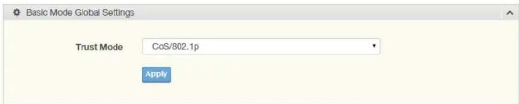
Figure 4.159 QoS > QoS Basic Mode > Global Settings
The following table describes the items in the previous figure.
Item Description
Trust Mode Click the drop-down menu to select the trust state of the QoS basic mode. Settings: None, CoS/802.1p, DSCP, CoS/802.1p-DSCP and IP Precedence.
Apply Click Apply to save the values and update the screen.
To access this page, click QoS > General > Global Settings.
The following figure displays the QoS Information settings.
| Information Name | Information Value |
| Trust Mode | CoS/002.1p |
Figure 4.160 QoS > General > Global Settings
4.8.2.2 Port Settings
The Port Settings page allows you to define a trust state (enabled or disabled) to a listed port.
To access this page, click QoS > QoS Basic Mode > Port Settings.
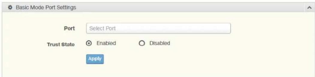
Figure 4.161 QoS > QoS Basic Mode > Port Settings
The following table describes the items in the previous figure.
Item Description
Port Enter the port number for the QoS basic mode setting.
Trust State Select Enabled or Disabled to set the port's trust state status.
Apply Click Apply to save the values and update the screen.
The ensuing table for QoS Port Status settings are informational only: Port and Trust State.
4.8.3 Rate Limit
Rate Limits features control on a per port basis. Bandwidth control is supported for the following: Ingress Bandwidth Control, Egress Bandwidth Control and Egress Queue.
4.8.3.1 Ingress Bandwidth Control
The Ingress Bandwidth Control page allows you to configure the bandwidth control for a listed port.
To access this page, click QoS > Rate Limit > Ingress Bandwidth Control.
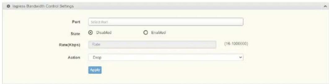
Figure 4.162 QoS > Rate Limit > Ingress Bandwidth Control
The following table describes the items in the previous figure.
Item Description
Port Enter the port number for the rate limit setup.
| State | Select Disabled or Enabled to set the port's state status. |
| Rate (Kbps) | Enter the value in Kbps (16 to 1000000) to set as the bandwidth rate for the selected port. |
| Action | Select the Ingress port action to be Drop or Shutdown. |
| Apply | Click Apply to save the values and update the screen. |
To access this page, click QoS > Rate Limit > Ingress Bandwidth Control.
The following figure displays the Ingress Bandwidth Control Recover Time settings.

Figure 4.163 QoS > Rate Limit > Ingress Bandwidth Control
To access this page, click QoS > Rate Limit > Ingress Bandwidth Control. The following figure displays the Ingress Bandwidth Control Status settings.
| Port | Ingress RateLimit (Kbps) | Action |
| GE1 | Off | Drop |
| GE2 | Off | Drop |
| GE3 | Off | Drop |
| GE4 | Off | Drop |
| GE5 | Off | Drop |
| GE6 | Off | Drop |
Figure 4.164 QoS > Rate Limit > Ingress Bandwidth Control
4.8.3.2 Egress Bandwidth Control
The Egress Bandwidth Control page allows you to set the egress bandwidth control for a listed port.
To access this page, click QoS > Rate Limit > Egress Bandwidth Control.
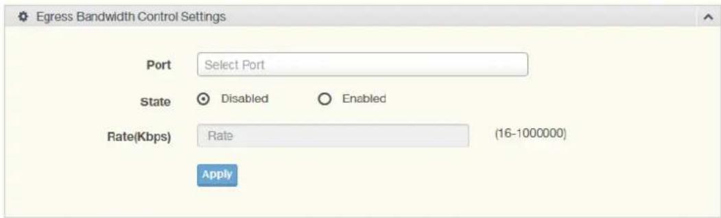
Figure 4.165 QoS > Rate Limit > Egress Bandwidth Control
The following table describes the items in the previous figure.
| Item Description |
| Port Enter the port number to set the Egress Bandwidth Control. |
| State Select Disabled or Enabled to set the Egress Bandwidth Control state. |
| Rate (Kbps) Enter the value in Kbps (16 to 1000000) to set the Egress Bandwidth rate. |
| Apply Click Apply to save the values and update the screen. |
To access this page, click QoS > Rate Limit > Egress Bandwidth Control. The following figure displays the Egress Bandwidth Control Status settings.
| Port | Egress RateLimit (Kbps) |
| GE1 | Off |
| GE2 | Off |
| GE3 | Off |
| GE4 | Off |
| GE5 | Off |
Figure 4.166 QoS > Rate Limit > Egress Bandwidth Control
4.8.3.3 Egress Queue
The Egress Queue page allows you to set the egress bandwidth parameters. To access this page, click QoS > Rate Limit > Egress Queue.
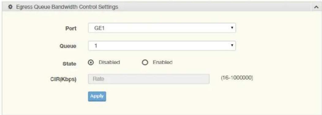
Figure 4.167 QoS > Rate Limit > Egress Queue
The following table describes the items in the previous figure.
| Item Description | |
| Port Click the drop-down menu to select the port to define the Egress queue. | |
| Queue Click the drop-down menu to set the queue order for the Egress setting. | |
| State | Click Disabled or Enabled to set the Egress queue state. |
| CIR (Kbps) Enter the value in Kbps (16 to 1000000) to set the CIR rate for the Egress queue. | |
| Apply Click Apply to save the values and update the screen. | |
The ensuing table for FE1 Egress Per Queue Status settings are informational only: Queue Id and Egress Rate Limit (Kbps).
4.8.4 Bandwidth Guarantee
4.8.4.1 Global Settings
To access this page, click QoS > Bandwidth Guarantee > Global Settings.
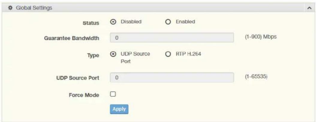
Figure 4.168 QoS > Bandwidth Guarantee > Global Settings
The following table describes the items in the previous figure.
| Item Description | |
| Status | Click Disabled or Enabled to set the guarantee bandwidth. |
| Guarantee Bandwidth | Enter the value for the guarantee bandwidth. |
| Type | Click UDP Source Port or RTP H.264 to set the guarantee bandwidth type. |
| UDP Source Port | Enter the port number for the UDP source. |
| Force Mode | Click the check box to enable the force mode. |
| Apply Click Apply to save the values and update the screen. | |
To access this page, click QoS > Bandwidth Guarantee > Global Settings.
The following figure displays the Ingress Bandwidth Control Status settings.
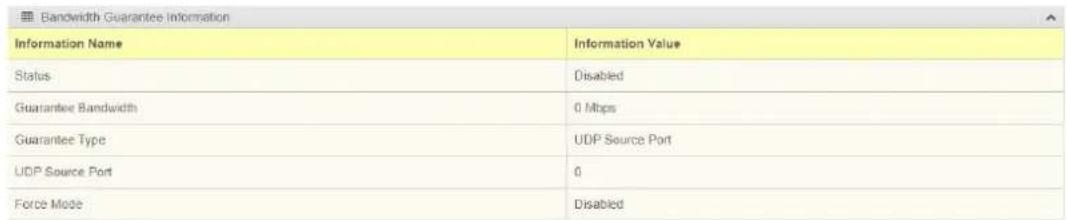
Figure 4.169 QoS > Bandwidth Guarantee > Global Settings
4.8.4.2 Utilization
To access this page, click QoS > Bandwidth Guarantee > Utilization.
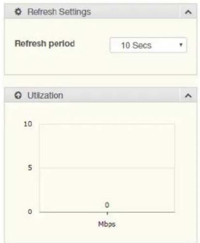
Figure 4.170 QoS > Bandwidth Guarantee > Utilization
The following table describes the items in the previous figure.
| Item Description |
| Refresh period Click the drop-down menu to select refresh time. |
| Apply Click Apply to save the values and update the screen. |
4.9 Management
4.9.1 LLDP
LLDP is a one-way protocol without request/response sequences. Information is advertised by stations implementing the transmit function, and is received and processed by stations implementing the receive function.
4.9.1.1 LLDP System Settings
The LLDP System Settings allows you to configure the status (enabled or disabled) for the protocol, set the interval for frame transmission, set the hold time multiplier and the re-initialization delay.
To access this page, click Management > LLDP > LLDP System Settings.
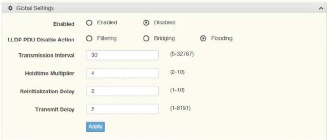
Figure 4.171 Management > LLDP > LLDP System Settings
The following table describes the items in the previous figure.
| Item Description | |
| Enabled | Click Enabled or Disabled to set the Global Settings state. |
| LLDP PDU Disable Action | Click to select the LLDP PDU handling action when LLDP is globally disabled. Options include: Filtered, Bridged, or Flooded. |
| Transmission Interval | Select the interval at which frames are transmitted. The default is 30 seconds, and the valid range is 5 to 32768 seconds. |
| Holdtime Multiplier | Select the multiplier on the transmit interval to assign to TTL. |
| Reinitialization Delay | Select the delay length before re-initialization. |
| Transmit Delay | Select the delay after an LLDP frame is sent. |
| Apply | Click Apply to save the values and update the screen. |
To access this page, click Management > LLDP > LLDP System Settings.
The following figure displays the LLDP Global Config settings.
| Configuration Name | Configuration Value |
| LLDP Enabled | Disabled |
| LLDP PDU Disable Action | Flooding |
| Transmission Interval | 30 Secs |
| Holdtime Multiplier | 4 |
| Resinitialization Delay | 2 Secs |
| Transmit Delay | 2 Secs |
Figure 4.172 Management > LLDP > LLDP System Settings
4.9.1.2 LLDP Port Settings
The LLDP Port Settings page allows you to configure the state (enabled or disabled) of the selected port.
To access this page, click Management > LLDP > LLDP Port Settings.
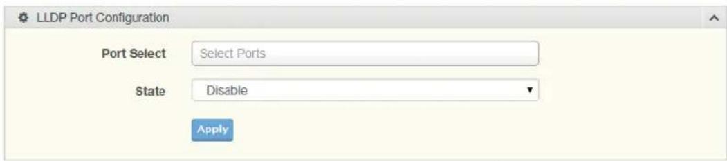
Figure 4.173 Management > LLDP > LLDP Port Settings > LLDP Port Configuration
The following table describes the items in the previous figure.
Item Description
Port Select Enter the port number associated with the LLDP setting.
State Click the drop-down menu to select the LLDP port state.
Apply Click Apply to save the values and update the screen.
The following figure displays the Optional TLVs Selection settings.
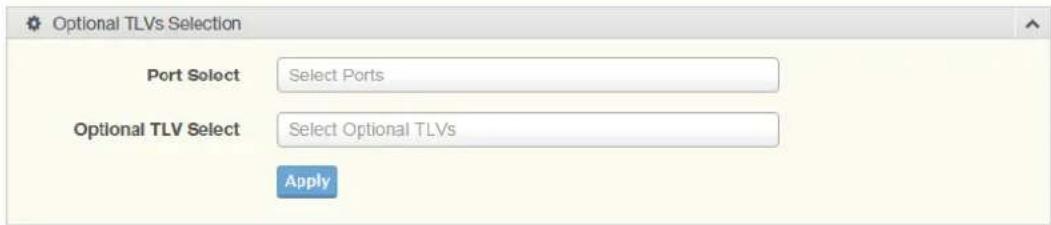
Figure 4.174 Management > LLDP > LLDP Port Settings > Optional TLVs Selection
The following table describes the items in the previous figure.
Item Description
Port Select Enter the port number associated with the TLV (optional) selection.
| Item | Description |
| Optional TLV Select Click the drop-down menu to select the LLDP optional TLVs to be carried (multiple selections are allowed).System Name: To include system name TLV in LLDP frames.Port Description: To include port description TLV in LLDP frames.System Description: To include system description TLV in LLDP frames.System Capability: To include system capability TLV in LLDP frames.802.3 MAC-PHY: To indicate the current duplex and bit rate settings of the device.802.3 Link Aggregation: To indicate the link can be aggregated.802.3 Maximum Frame Size: To indicate the maximum frame size capability of the MAC-PHY implementation.Management Address: To select the advertising IP management address.802.1 PVID: To select to advertise the PVID in the TLV. | |
| Apply | Click Apply to save the values and update the screen. |
The following figure displays the LLDP Port Status settings.
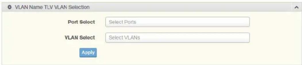
Figure 4.175 Management > LLDP > LLDP Port Settings > VLAN Name TLV VLAN Selection
The following table describes the items in the previous figure.
| Item | Description |
| Port Select | Enter the port number to associated with the TLV selection. |
| VLAN Select | Select the VLAN Name ID to be carried out (multiple selection is allowed). |
| Apply | Click Apply to save the values and update the screen. |
The ensuing table for LLDP Port VLAN TLV Status settings are informational only: Port and Selected VLAN.
4.9.1.3 LLDP Local Device Info
The LLDP Local Device Info page allows you to view information regarding network devices, providing that the switch has already obtained LLDP information on the devices.
To access this page, click Management > LLDP > LLDP Local Device Info.
The following figure displays the Local Device Summary settings.
| Local Device Summary | |
| Information Name | Information Value |
| Chassis ID Subtype | MAC Address |
| Chassis ID | 00 0B:AB:F8:9D:95 |
| System Name | Switch |
| System Description | switch |
| Capabilities Supported | Bridge |
| Capabilities Enabled | Bridge |
| Port ID Subtype | Interface name |
Figure 4.176 Management > LLDP > LLDP Local Device Info
To access this page, click Management > LLDP > LLDP Local Device Info.
The following figure displays the Port Status settings.
| Port Status | ||
| Detail | Port | Selected VLAN |
| Og | GE1 | TX & RX |
| Og | GE2 | TX & RX |
| Og | GE3 | TX & RX |
| Og | GE4 | TX & RX |
| Og | GE6 | TX & RX |
| Og | GE8 | TX & RX |
| Og | GE7 | TX & RX |
Figure 4.177 Management > LLDP > LLDP Local Device Info
4.9.1.4 LLDP Remote Device Info
The LLDP Remote Device Info page allows you to view information about remote devices, LLDP information must be available on the switch.
To access this page, click Management > LLDP > LLDP Remote Device Info.

Figure 4.178 Management > LLDP > LLDP Remote Device Info
The following table describes the items in the previous figure.
Item Description
Detail Click to display the device details.
Delete Click to delete the selected devices.
Refresh Click to refresh the remote device information list.
4.9.1.5 LLDP Overloading
To access this page, click Management > LLDP > LLDP Overloading.
The following figure displays the LLDP Overloading settings.
| Port | Total (Bytes) | Left to Send (Bytes) | Status | Status | |||
| Mandatory TLVs | 802.3 TLVs | Optional TLVs | 802.1 TLVs | ||||
| GE1 | 29 | 1459 | Not Overloading | 21(Transmitted) | 8(Transmitted) | ||
| GE2 | 29 | 1459 | Not Overloading | 21(Transmitted) | 8(Transmitted) | ||
| GE3 | 29 | 1459 | Not Overloading | 21(Transmitted) | 8(Transmitted) | ||
| GE4 | 29 | 1459 | Not Overloading | 21(Transmitted) | 8(Transmitted) | ||
| GE5 | 29 | 1459 | Not Overloading | 21(Transmitted) | 8(Transmitted) | ||
| GE6 | 29 | 1459 | Not Overloading | 21(Transmitted) | 8(Transmitted) | ||
| GE7 | 29 | 1459 | Not Overloading | 21(Transmitted) | 8(Transmitted) | ||
| GE8 | 29 | 1459 | Not Overloading | 21(Transmitted) | 8(Transmitted) | ||
Figure 4.179 Management > LLDP > LLDP Overloading
4.9.2 SNMP
Simple Network Management Protocol (SNMP) is a protocol to facilitate the monitoring and exchange of management information between network devices. Through SNMP, the health of the network or status of a particular device can be determined.
4.9.2.1 SNMP Settings
The SNMP Settings page allows you to set the SNMP daemon state (enabled or disabled).
To access this page, click Management > SNMP > SNMP Settings.

Figure 4.180 Management > SNMP > SNMP Settings
The following table describes the items in the previous figure.
Item Description
State Click Enabled or Disabled to define the SNMP daemon.
Apply Click Apply to save the values and update the screen.
The ensuing table for SNMP Information settings are informational only: SNMP.
4.9.2.2 SNMP Community
The SNMP Community page provides configuration options for the community. SNMP v1 and SNMP v2c use the group name (Community Name) certification. It's role is similar to the password function. If SNMP v1 and SNMP v2c are used, you can go directly from the configuration settings to this page to configure the SNMP community.
To access this page, click Management > SNMP > SNMP Community.
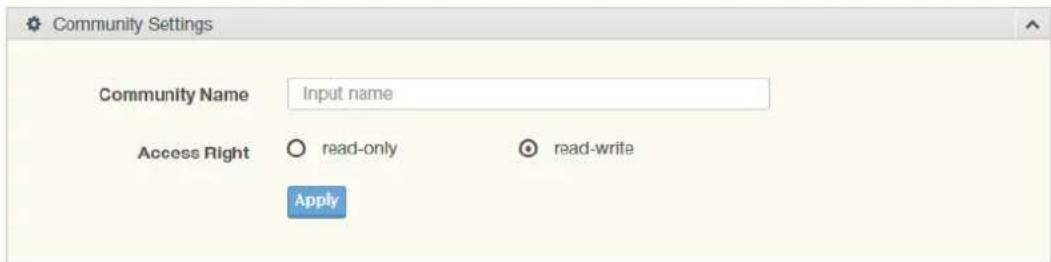
Figure 4.181 Management > SNMP > SNMP Community
The following table describes the items in the previous figure.
Item Description
Community Name Enter a community name (up to 20 characters).
Access Right Click the radio box to specify the access level (read only or read write)
Apply Click Apply to save the values and update the screen.
To access this page, click Management > SNMP > SNMP Community. The following figure displays the Community Status settings.
| Community Status | |||
| No. | Community Name | Access Right | Action |
| 1 | public | read-only | Delete |
| 2 | private | read-write | Delete |
Figure 4.182 Management > SNMP > SNMP Community
4.9.2.3 SNMPv3 EngineID
To access this page, click Management > SNMP > SNMPv3 EngineID.

Figure 4.183 Management > SNMP > SNMPv3 EngineID
The following table describes the items in the previous figure.
Item Description
SNMP EngineID Enter the hexadecimal string to define the engine ID for SNMPv3 agent.
4.9.2.4 SNMPv3 Settings
The SNMPv3 Settings page allows you to create SNMP groups. The users have the same level of security and access control permissions as defined by the group settings.
To access this page, click Management > SNMP > SNMPv3 Settings.
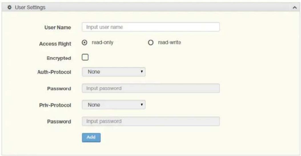
Figure 4.184 Management > SNMP > SNMPv3 Settings
The following table describes the items in the previous figure.
| Item Description | |
| User Name Enter a user name (up to 32 characters) to create an SNMP profile. | |
| Access Right | Click read-only or read-write to define the access right for the profile. |
| Encrypted Click the option to set the encrypted option for the user setting. | |
| Auth-Protocol | Click the drop-down menu to select the authentication level: MD5 or SHA. The field requires a user password.MD5: specify HMAC-MD5-96 authentication levelSHA: specify HMAC-SHA authentication protocol |
| Password | Enter the characters to define the password associated with the authentication protocol. |
| Priv-Protocol | Click the drop-down menu to select an authorization protocol: none or DES.The field requires a user password.None: no authorization protocol in useDES: specify 56-bit encryption in use |
| Password | Enter the characters to define the password associated with the authorization protocol. |
| Add | Click Add to save the values and update the screen. |
The ensuing table for User Status settings are informational only: User Name, Access Right, Auth-Protocol, Priv-Protocol and Delete (click to delete the desired user name).
4.9.2.5 SNMP Trap
The SNMP Trap page allows you to set the IP address of the node and the SNMP credentials corresponding to the version that is included in the trap message.
To access this page, click Management > SNMP > SNMP Trap.
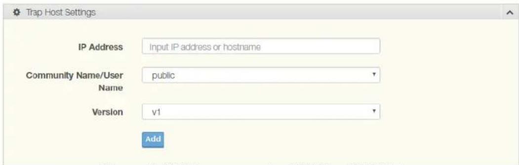
Figure 4.185 Management > SNMP > SNMP Trap
The following table describes the items in the previous figure.
| Item | Description |
| IP Address | Enter the IP address to designate the SNMP trap host. |
| Community Name/User Name | Click the drop-down menu to select a defined community name. |
| Version | Click the drop-down menu to designate the SNMP version credentials (v1, v2c - trap, v2c - inform, v2c - trap or v2c - inform). |
| Add | Click Add to save the values and update the screen. |
The ensuing table for Trap Host Status settings are informational only: No., IP Address, Community Name, Version and Delete (click to delete the desired IP address).
4.9.3 Power Over Ethernet
Power Over Ethernet is the function supplying power to Powered Devices (PD) through the switch in the event that AC power is not readily available.
Power over Ethernet can be used for the following areas:
■ Surveillance devices
■ I/O sensors for security requirements
■ Wireless access points
| Series | Supported Models |
| EKI | EKI-7720G-4FPI |
4.9.3.1 PoE System Settings
The PoE System Settings page allows you to configure the overload disconnect and the maximum available wattage.
To access this page, click Management > Power Over Ethernet > PoE System Settings.
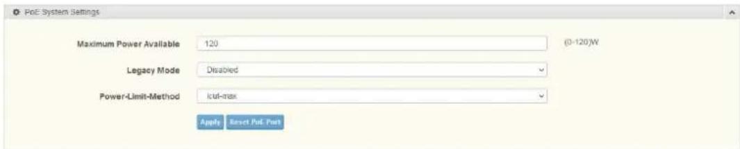
Figure 4.186 Management > Power Over Ethernet > PoE System Settings
The following table describes the items in the previous figure.
| Item Description | |
| Maximum Power Available | Select the value in Watts to set the maximum available power. |
| Legacy Mode | Click the drop-down menu to disable or enable the PoE legacy mode. |
| Power-Limit-Method | Click the drop-down menu to select the limit method for the PoE power setting. The following options are available: ■ user-defined-power-limit ■ power-limit-from-class ■ lcut-max |
| Apply | Click Apply to save the values and update the screen. |
| Reset PoE Port | Click Reset PoE Port to reset the PoE settings to default value. |
The ensuing figure displays the PoE System Information screen. The following information displays: Actual Power Consumption, Current Power Available, Maximum Power Available, Legacy Mode, Overload Disconnect Type and PoE Port Power Limit Method (PLFC).
| Information Name | Information Value |
| Actual Power Consumption | 0.0 W |
| Current Power Available | 120.0 W |
| Maximum Power Available | 120.0 W |
| Legacy Mode | Disabled |
| Overload Disconnect Type | Overload Port First |
| PoE Port Power Limit Method(PLFC) | LCUT Max(According to port behavior) |
Figure 4.187 Management > Power Over Ethernet > PoE System Settings
4.9.3.2 PoE Port Settings
The PoE Port Settings page allows you to configure the port status, its power limitations, legacy mode status, and power limit settings.
To access this page, click Management > Power Over Ethernet > PoE Port Settings.
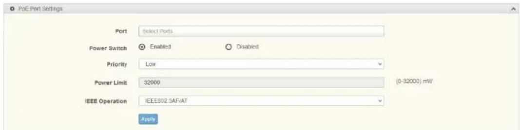
Figure 4.188 Management > Power Over Ethernet > PoE Port Settings
The following table describes the items in the previous figure.
| Item Description | |
| Port | Click the drop-down menu to select a PoE port. |
| Power Switch | Select Enabled or Disabled to designate the PoE port function by ports. |
| Priority | Click the drop-down menu to configure the power supply priority: Critical, Low, Medium or High. Default is Low. |
| Power Limit | Enter a number to set the port power current limitation to be given to the Powered Device (PD) |
Item Description
IEEE Operation Click the drop-down menu to select an IEEE operation feature. The following options are available:
IEEE802.3AF/AT
IEEE802.3AF
Apply Click Apply to save the values and update the screen.
The ensuing figure displays the PoE Config Information screen. The following information displays: Port, Switch State, Priority, Power Limit(W) and IEEE Operation Type.
| Port | Switch State | Priority | Power Limit(W) | IEEE Operation Type |
| gi 1 | Enabled | Low | 32.000 | IEEE802.3AF/AT |
| gi 2 | Enabled | Low | 32.000 | IEEE802.3AF/AT |
| gi 3 | Enabled | Low | 32.000 | IEEE802.3AF/AT |
| gi 4 | Enabled | Low | 32.000 | IEEE802.3AF/AT |
| gi 5 | Enabled | Low | 32.000 | IEEE802.3AF/AT |
| gi 6 | Enabled | Low | 32.000 | IEEE802.3AF/AT |
| gi 7 | Enabled | Low | 32.000 | IEEE802.3AF/AT |
| gi 8 | Enabled | Low | 32.000 | IEEE802.3AF/AT |
Figure 4.189 Management > Power Over Ethernet > PoE Port Config Information
4.9.4 TCP Modbus Settings
The TCP Modbus function allows for client-server communication between a switch module (server) and a device in the networking running MODBUS client software (client).
4.9.4.1 TCP Modbus Settings
The TCP Modbus Settings page allows you to configure the modbus function.
To access this page, click Management > TCP Modbus Settings > TCP Modbus Settings.
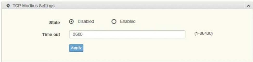
Figure 4.190 Management > TCP Modbus Settings > TCP Modbus Settings The following table describes the items in the previous figure.
Item Description
State Click Disabled or Enabled to set the TCP Modbus state.
Time out Enter the value (1 to 86400) to define the timeout period between transport time.
Apply Click Apply to save the values and update the screen.
To access this page, click Management > TCP Modbus Settings > TCP Modbus Settings.
The following figure displays the TCP Modbus Status settings.
| Information Name | Information Value |
| TCP Modbus Status | Disabled |
| TCP Modbus Times Out | 3600 |
Figure 4.191 Management > TCP Modbus Settings > TCP Modbus Settings
4.9.5 DHCP Server
The Dynamic Host Configuration Protocol (DHCP) is a network protocol enabling a server to automatically assign an IP address to a computer from a defined range of numbers configured for a given network.
4.9.5.1 Status Settings
The Status Settings page allows you to configure the DHCP server mode (enabled or disabled).
To access this page, click Management > DHCP Server > Status Settings.

Figure 4.192 Management > DHCP Server > Status Settings
The following table describes the items in the previous figure.
| Item Description | |
| DHCP Server | Select Enable or Disable to designate the DHCP server function type.When a new DHCP server mode is selected, the switch requires a system restart for the new mode to take effect. |
| Apply | Click Apply to save the values and update the screen. |
| Restart | Click Restart to have the switch perform a system restart function. In the event that the IP settings are changed, the DHCP server must be restarted for the IP settings to take effect. |
The ensuing table for Status Information settings are informational only: DHCP Server Service.
4.9.5.2 Global Settings
The Global Settings page allows you to configure the global settings for the DHCP function.
To access this page, click Management > DHCP Server > Global Settings.
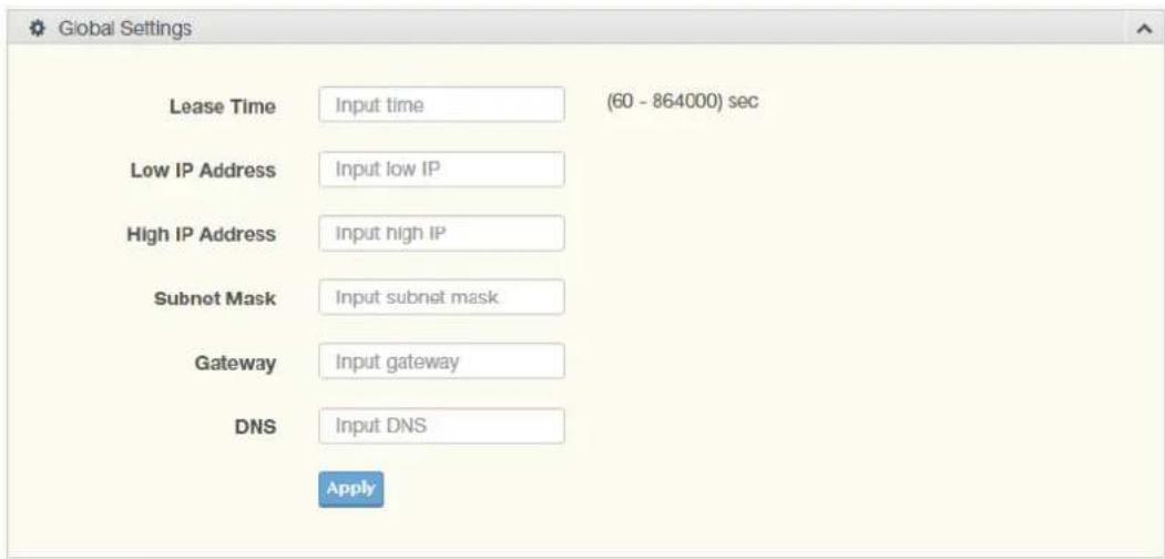
Figure 4.193 Management > DHCP Server > Global Settings
The following table describes the items in the previous figure.
| Item Description |
| Lease Time Type in the value designating the lease time (60 - 864000) in seconds for each setting lease. |
| Low IP Address Type in the value designating the lowest range in the IP address pool. |
| High IP Address Type in the value designating the highest range in the IP address pool. |
| Subnet Mask Type in the value designating the subnet mask for the IP address pool. |
| Gateway Type in the value designating the gateway for the IP address pool. |
| DNS Type in the value designating the DNS for the IP address pool. |
| Apply Click Apply to save the values and update the screen. |
To access this page, click Management > DHCP Server > Global Settings.
The following figure displays the Global Information settings.
| Information Name | Information Value |
| Lease time | 08400 sec |
| Low IP Address | 0.0.0.0 |
| High IP Address | 0.0.0.0 |
| Subnet Mask | 0.0.0.0 |
| Gateway | 0.0.0.0 |
| DNS | 0.0.0.0 |
| Clear IP Pool | Clear |
Figure 4.194 Management > DHCP Server > Global Settings
4.9.5.3 Port Settings
The Port Settings page allows you to configure selected ports for the DHCP function.
To access this page, click Management > DHCP Server > Port Settings.
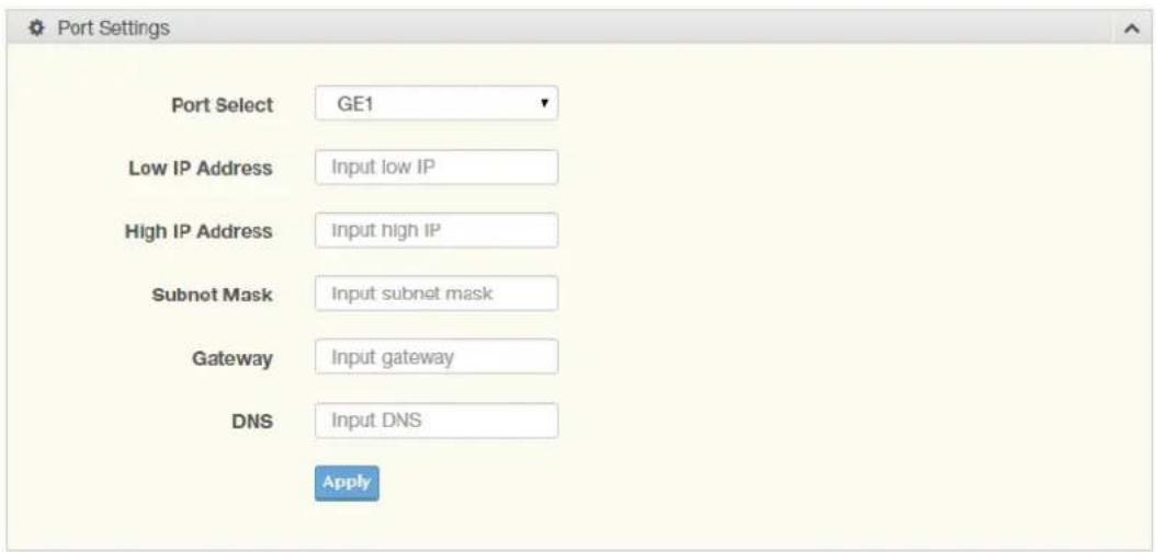
Figure 4.195 Management > DHCP Server > Port Settings
The following table describes the items in the previous figure.
Item Description
Port Select Click the drop-down menu to select a pre-defined port to configure. The suboptions are designated for the selected port.
Low IP Address Type in the value designating the lowest range in the IP address pool.
4.9.5.4 Option 82 Settings
The Option 82 Settings, also known as the DHCP relay agent information option, provide information about the network location of a DHCP client. In turn, the DHCP server uses the information to implement IP addresses or other parameters for the client.
To access this page, click Management > DHCP Server > Option 82 Settings.
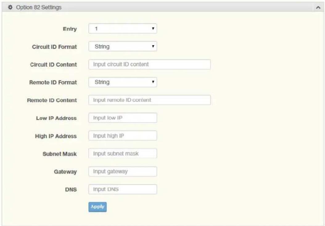
Figure 4.196 Management > DHCP Server > Option 82 Settings
The following table describes the items in the previous figure.
Item Description
Entry Click the drop-down menu to select an entry for the Option 82 setting.
Circuit ID Format Click the drop-down menu to select the format of the circuit ID: string or hex.
Circuit ID Content Enter the circuit ID string on the switch on which the request was received.
Remote ID Format Click the drop-down menu to select the format of the remote ID: string or hex.
Remote ID Content Enter the remote ID string of the host.
Low IP Address Type in the value designating the lowest range in the IP address pool.
High IP Address Type in the value designating the highest range in the IP address pool.
Subnet Mask Type in the value designating the subnet mask for the IP address pool.
Gateway Type in the value designating the gateway for the IP address pool.
DNS Type in the value designating the DNS for the IP address pool.
Apply Click Apply to save the values and update the screen.
To access this page, click Management > DHCP Server > Option 82 Settings.
The following figure displays the Entry Information settings.
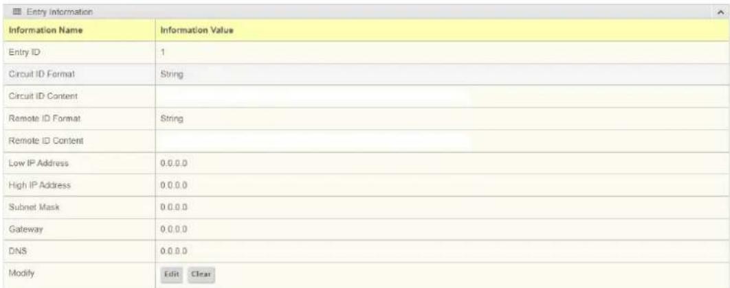
Figure 4.197 Management > DHCP Server > Option 82 Settings
4.9.5.5 Client MAC Settings
To access this page, click Management > DHCP Server > Client MAC Settings.
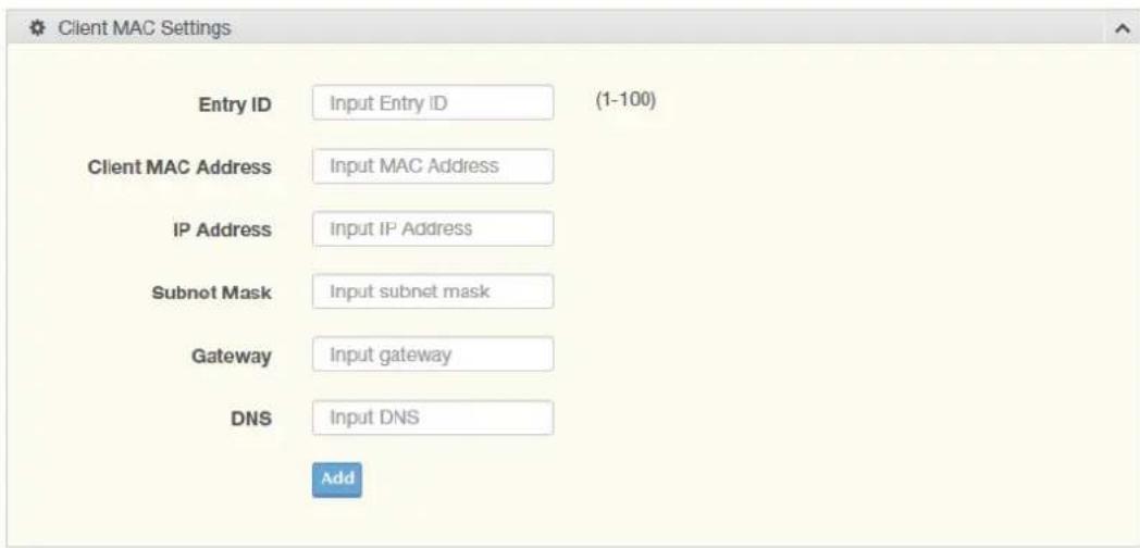
Figure 4.198 Management > DHCP Server > Client MAC Settings
The following table describes the items in the previous figure.
Item Description
| Entry ID Type in the value designating the entry ID. | |
| Client MAC Address Enter the MAC address for DHCP server. | |
| IP Address | Enter a value to specify the IP address of the interface. |
| Subnet Mask | Enter a value to specify the IP subnet mask for the interface. |
| Gateway | Enter a value to specify the gateway for the interface. |
| DNS | Enter a value to specify the DNS server for the interface. |
| Apply | Click Apply to save the values and update the screen. |
The ensuing table for Client MAC Information settings are informational only: Entry ID, Client MAC Address, IP Address, Subnet Mask and Modify (Click Detail to display the detail information of desired entry id or Delete to delete the desired entry id).
4.9.5.6 Lease Entry
To access this page, click Management > DHCP Server > Lease Entry.
The following figure displays the Lease entry Table settings.

Figure 4.199 Management > DHCP Server > Lease Entry
4.9.6 SMTP Client
Simple Mail Transfer Protocol (SMTP) is a protocol to send e-mail messages between servers. SMTP is used to send messages from a mail client to a mail server. SMTP by default uses TCP port 25.
4.9.6.1 Global Settings
The Global Settings page allows you to set the active profile for the SMTP client.
To access this page, click Management > SMTP Client > Global Settings.
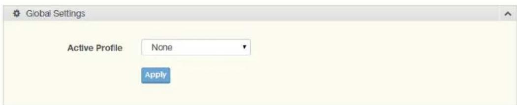
Figure 4.200 Management > SMTP Client > Global Settings
The following table describes the items in the previous figure.
Item Description
Active Profile Click the drop-down menu to select the profile status (None, 1 or 2).
Apply Click Apply to save the values and update the screen.
The ensuing table for SMTP Information settings are informational only: Active Profile Id.
4.9.6.2 Profile Settings
The Profile Settings page allows you to select the server IP, the server port, and sender mail for the listed profile.
To access this page, click Management > SMTP Client > Profile Settings.
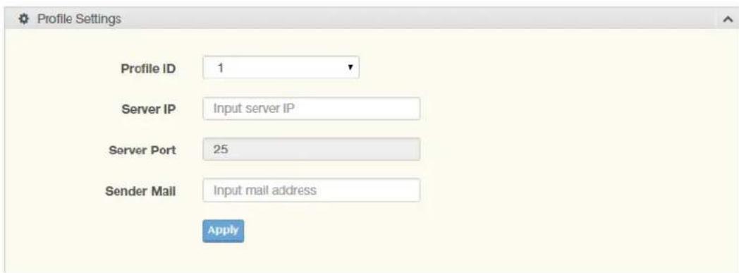
Figure 4.201 Management > SMTP Client > Profile Settings > Profile Settings
The following table describes the items in the previous figure.
Item Description
Profile ID Click the drop-down menu to select the identification type for the profile (1 or 2).
Server IP Enter the IP address to designate the server host.
Server Port Enter the port number to designate the port associated with the server IP address.
Sender Mail Enter the email address of the sender client.
Apply Click Apply to save the values and update the screen.
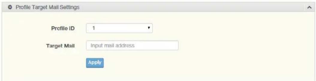
Figure 4.202 Management > SMTP Client > Profile Settings > Profile Target Mail Settings
The following table describes the items in the previous figure.
Item Description
Profile ID Click the drop-down menu to select the identification type for the profile (1 or 2).
Target Mail Enter the email address of the target client.
Apply Click Apply to save the values and update the screen.
To access this page, click Management > SMTP Client > Profile Settings > Profile Target Mail Settings.
The following figure displays the Profile Information settings.
| Information Name | Information Value | Delete |
| Profile ID | 1 | |
| Server IP | 0.0.0.0 | |
| Server Port | 25 | |
| Sender Mail Address |
Figure 4.203 Management > DHCP Server > Lease Entry
4.9.6.3 Sending Message
The Sending Message page allows you to setup the log message for use with the SMTP client.
To access this page, click Management > SMTP Client > Sending Message.
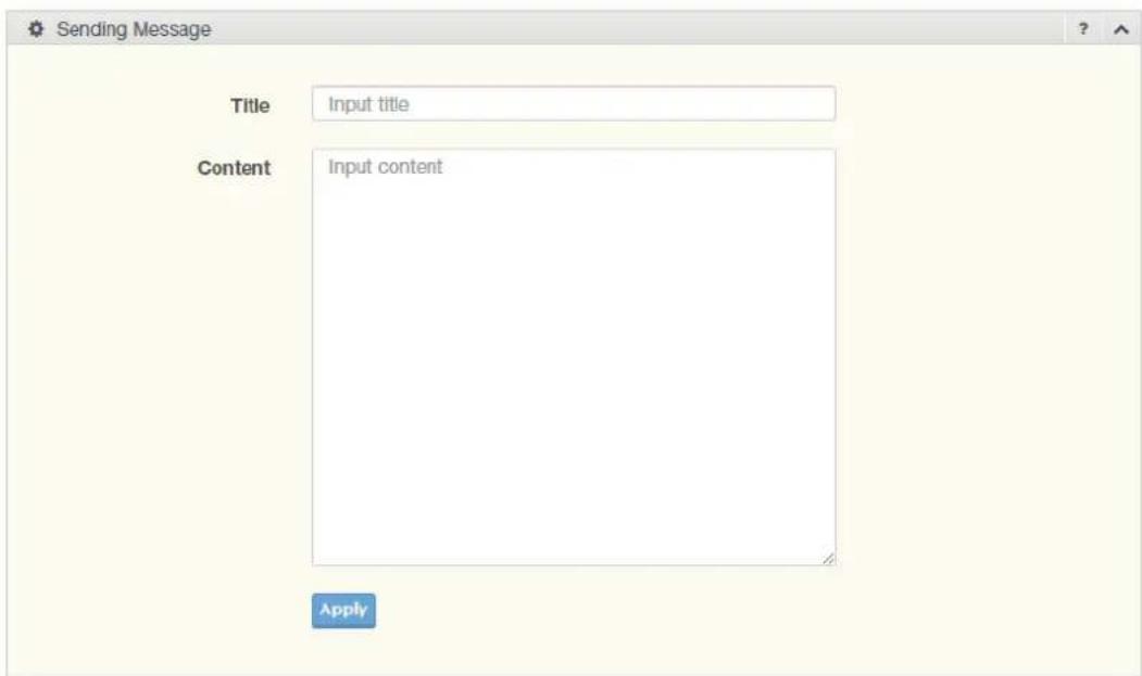
Figure 4.204 Management > SMTP Client > Sending Message
The following table describes the items in the previous figure.
Item Description
Title Assign the title of the email. The maximum length is 20 characters (alphanumeric, symbols (. (dot), _ (underline), - (dash line) and space).
Content Assign the content of the email. The maximum length is 64 characters (alphanumeric, symbols (. (dot), _ (underline), - (dash line) and space).
Apply Click Apply to save the values and update the screen.
4.9.7 RMON
Remote monitoring (RMON) uses a client-server model to monitor/manage remote devices on a network.
4.9.7.1 RMON Statistics
The RMON Statistics page allows you to view information regarding packet sizes and information for physical layer errors. The information displayed is according to the RMON standard.
To access this page, click Management > RMON > RMON Statistics.
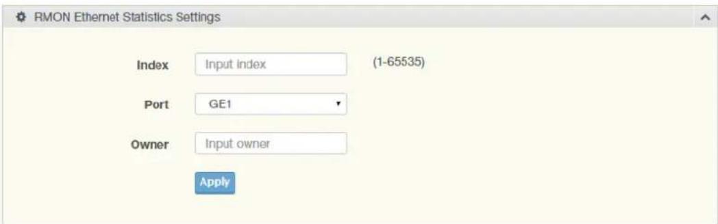
Figure 4.205 Management > RMON > Rmon Statistics
The following table describes the items in the previous figure.
Item Description
| Index | Enter an entry selection (1 to 65535) to display its statistical information. |
| Port | Enter the respective port number for the selected entry. |
| Owner | Enter the name of the owner of the RMON group. |
Apply Click Apply to save the values and update the screen.
The ensuing table for Statistics Information settings are informational only: Index, Port, Drop Events, Octets, Packets, Broadcast, Multicast, Owner and Delete (click to delete the desired index).
4.9.7.2 RMON History
The RMON History page allows you to configure the display of history entries.
To access this page, click Management > RMON > RMON History.
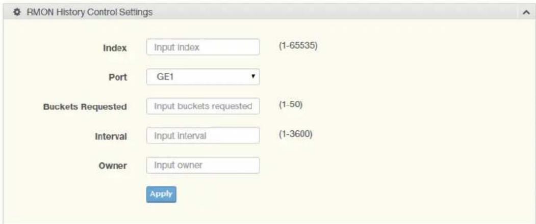
Figure 4.206 Management > RMON > RMON History
The following table describes the items in the previous figure.
Item Description
| Index Enter the index entry (1 to 65535) to select the number of new history table entries. |
Port Select the specific port switch.
| Buckets Requested Enter the specific (1-50) number of samples to store. | |
| Interval | Enter value in seconds (1 to 3600) to designate a specific interval time for the collection of samples. |
| Owner | Enter the name of the owner of the RMON history group. |
| Apply | Click Apply to save the values and update the screen. |
The ensuing table for History Information settings are informational only: Index, Port, Buckets Requested, Interval, Owner and Delete (click to delete the desired index).
4.9.7.3 RMON Alarm
The RMON Alarm page allows you to configure RMON statistics group and alarm groups.
To access this page, click Management > RMON > RMON Alarm.
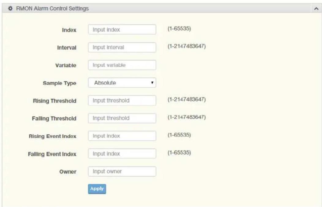
Figure 4.207 Management > RMON > Rmon Alarm
The following table describes the items in the previous figure.
| Item Description | |
| Index Enter the index entry (1 to 65535) to define a specific Alarm Collection history entry. | |
| Interval Enter a value (1 to 2147483647) to define the interval value for the Alarm Collection history. | |
| Variable Enter the alarm variables to define the monitoring triggers. | |
| Sample Type Enter the variable sample type. | |
| Rising Threshold | Enter the rising alarm threshold trigger. |
| Falling Threshold | Enter the falling alarm threshold trigger. |
| Rising Event Index | Enter the rising event index (1-65535) to define the alarm group. |
| Falling Event Index | Enter the falling event index (1-65535) to define the alarm group. |
| Owner | Enter the name of the owner of the RMON alarm group. |
| Apply | Click Apply to save the values and update the screen. |
The ensuing table for Alarm Information settings are informational only: Index, Interval, Variable, Sample Type, Rising Threshold, Falling Threshold, Rising Event Index, Falling Event Index, Owner and Delete (click to delete the desired index).
4.9.7.4 RMON Event
The RMON Event page is used to configure RMON event groups.
To access this page, click Management > RMON > RMON Event.
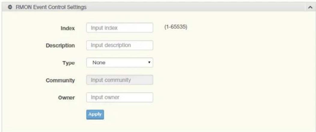
Figure 4.208 Management > RMON > RMON Event
The following table describes the items in the previous figure.
Item Description
Index Enter the index entry (1 to 65535) to define a specific RMON event.
Description Enter a value (1 to 2147483647) to define the interval value for the Alarm Collection history.
Type Click the drop-down menu to define the event type: None, Log, SNMP Trap, Log and Trap.
Community Enter the community string to be passed for the specified event.
Owner Enter the name of the owner of the RMON event.
Apply Click Apply to save the values and update the screen.
The ensuing table for Event Information settings are informational only: Index, Description, Type, Community, Owner and Delete (click to delete the desired index).
4.9.8 NTP Server
To access this page, click Management > NTP Server.
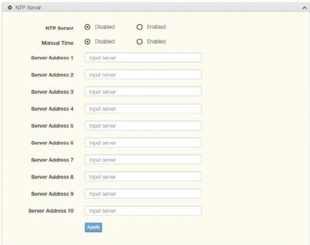
Figure 4.209 Management > NTP Server
The following table describes the items in the previous figure.
Item Description
NTP Server Click the radio button to enable or disable the NTP server function.
Manual Time Click the radio button to enable or disable the manual time function.
Server Address 1 \~ Enter the address of the NTP server. This is a text string of up to 64 Server Address 10 characters containing the encoded unicast IP address or hostname of a NTP server.
Apply Click Apply to save the values and update the screen.
The ensuing table for NTP Server Status settings are informational only: INTP Server Status, Manual Time, Server AddressInformation Value, Server 1, Server 2, Server 3, Server 4, Server 5, Server 6, Server 7, Server 8, Server 9 and Server 10.
4.10 Diagnostics
Through the Diagnostics function configuration of settings for the switch diagnostics is available.
4.10.1 Cable Diagnostics
The Cable Diagnostics page allows you to select the port for applying a copper test. To access this page, click Diagnostics > Cable Diagnostics.
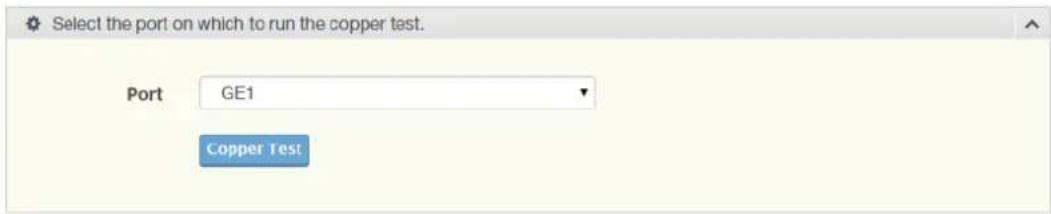
Figure 4.210 Diagnostics > Cable Diagnostics
The following table describes the items in the previous figure.
| Item Description | |
| Port Click the drop-down menu to select a pre-defined port for diagnostic testing. Giga ports are displayed with a channel A to D designation. | |
| Copper Test | Click Copper Test to display the test result for the selected port. |
The ensuing table for Test Result settings are informational only: Port, Channel A, Cable Length A, Channel B, Cable Length B, Channel C, Cable Length C, Channel D and Cable Length D.
4.10.2 Ping Test
The Ping Test page allows you to configure the test log page. To access this page, click Diagnostics > Ping Test.
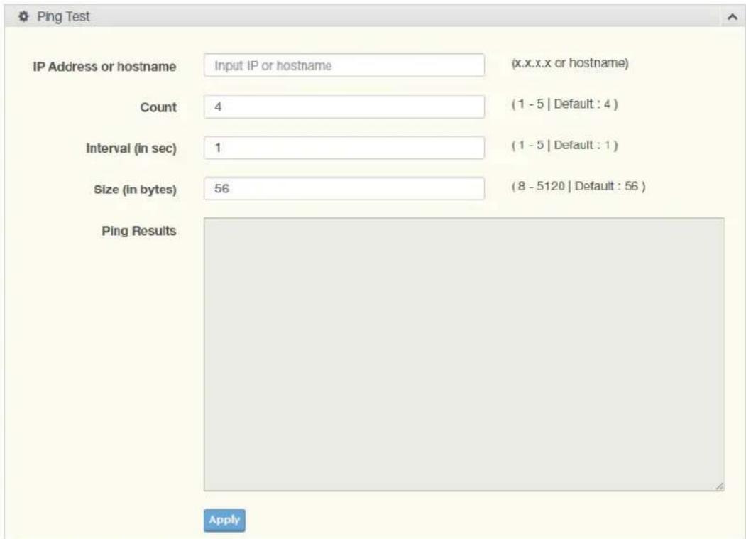
Figure 4.211 Diagnostics > Ping Test
The following table describes the items in the previous figure.
Item Description
| IP Address Enter the IP address or host name of the station to ping. The initial value is blank. The IP Address or host name you enter is not retained across a power cycle. Host names are composed of series of labels concatenated with periods. Each label must be between 1 and 63 characters long, maximum of 64 characters. |
| Count Enter the number of echo requests to send. The default value is 4.The value ranges from 1 to 5. The count entered is not retained across a power cycle. |
| Interval (in sec) Enter the interval between ping packets in seconds. The default value is 1. The value ranges from 1 to 5. The interval entered is not retained across a power cycle. |
| Size (in bytes) Enter the size of ping packet. The default value is 56. The value ranges from 8 to 5120. The size entered is not retained across a power cycle. |
| Ping Results Display the reply format of ping.PING 172.17.8.254 (172.17.8.254): 56 data bytes--- 172.17.8.254 ping statistics ---4 packets transmitted, 0 packets received, 100% packet lossOrPING 172.17.8.93 (172.17.8.93): 56 data bytes64 bytes from 172.17.8.93: icmp_seq=0 ttl=128 time=0.0 ms64 bytes from 172.17.8.93: icmp_seq=1 ttl=128 time=0.0 ms64 bytes from 172.17.8.93: icmp_seq=2 ttl=128 time=0.0 ms64 bytes from 172.17.8.93: icmp_seq=3 ttl=128 time=0.0 ms--- 172.17.8.93 ping statistics ---4 packets transmitted, 4 packets received, 0% packet lossround-trip min/avg/max = 0.0/0.0/0.0 ms |
| Apply Click Apply to display ping result for the IP address. |
4.10.3 IPv6 Ping Test
The IPv6 Ping Test page allows you to configure the Ping Test for IPv6.
To access this page, click Diagnostics > IPv6 Ping Test.
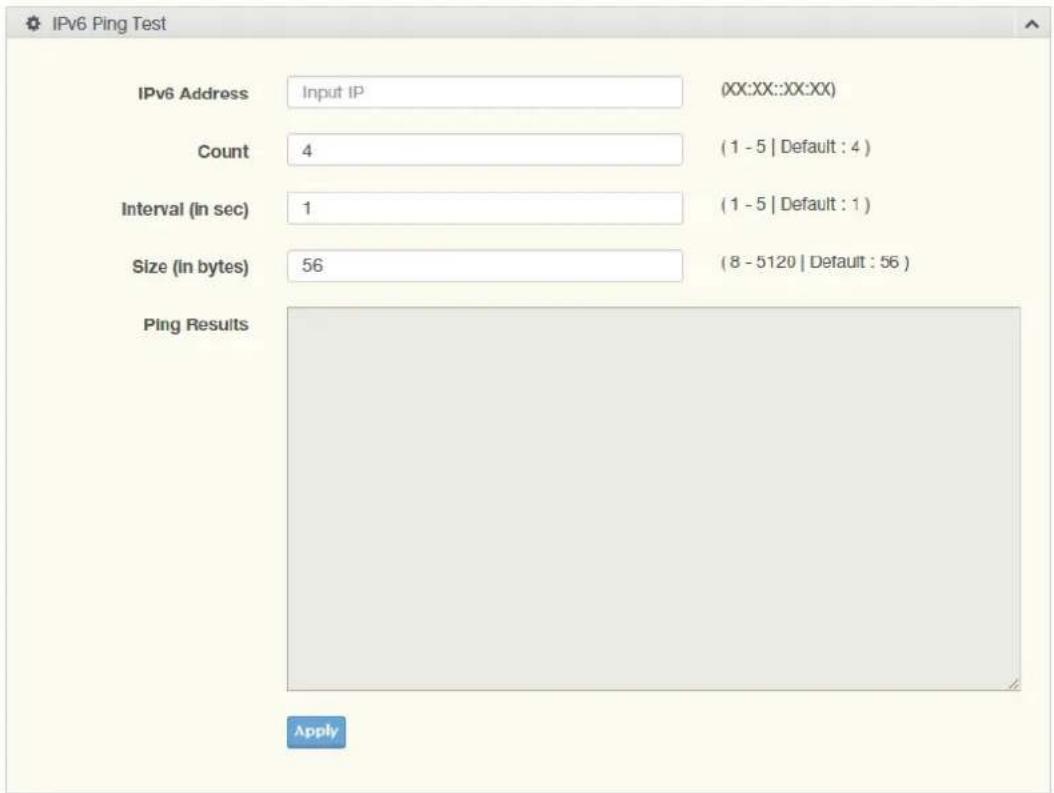
Figure 4.212 Diagnostics > IPv6 Ping Test
The following table describes the items in the previous figure.
Item Description
| IPv6 Address Enter the IP address or host name of the station you want the switch to ping. The initial value is blank. The IP Address or host name you enter is not retained across a power cycle. Host names are composed of series of labels concatenated with dots. Each label must be between 1 and 63 characters long, and the entire hostname has a maximum of 64 characters. |
| Count Enter the number of echo requests you want to send. The default value is 4. The value ranges from 1 to 5. The count you enter is not retained across a power cycle. |
| Interval (in sec) Enter the interval between ping packets in seconds. The default value is 1. The value ranges from 1 to 5. The interval you enter is not retained across a power cycle. |
| Size (in bytes) Enter the size of ping packet. The default value is 56. The value ranges from 8 to 5120. The size you enter is not retained across a power cycle. |
Item Description
Ping Results Display the reply format of ping.
PING 2222::777 (2222::777): 56 data bytes
--- 2222::777 ping statistics ---
4 packets transmitted, 0 packets received, 100% packet loss
Or
PING 2222::717 (2222::717): 56 data bytes
64 bytes from 2222::717: icmp6_seq=0 ttl=128 time=10.0 ms
64 bytes from 2222::717: icmp6_seq=1 ttl=128 time=0.0 ms
64 bytes from 2222::717: icmp6_seq=2 ttl=128 time=0.0 ms
64 bytes from 2222::717: icmp6_seq=3 ttl=128 time=0.0 ms
--- 2222::717 ping statistics ---
4 packets transmitted, 4 packets received, 0% packet loss
round-trip min/avg/max = 0.0/2.5/10.0 ms
Apply Click Apply to display ping result for the IP address.
4.10.4 System Log
4.10.4.1 Logging Service
The Logging Service page allows you to setup the logging services feature for the system log.
To access this page, click Diagnostics > System Log > Logging Service.

Figure 4.213 Diagnostics > System Log > Logging Service
The following table describes the items in the previous figure.
Item Description
Logging Service Click Enabled or Disabled to set the Logging Service status.
Apply Click Apply to save the values and update the screen.
The ensuing table for Logging Information settings are informational only: Logging Service.
4.10.4.2 Local Logging
The Local Logging page allows you to designate a local target when the severity criteria is reached.
To access this page, click Diagnostics > System Log > Local Logging.
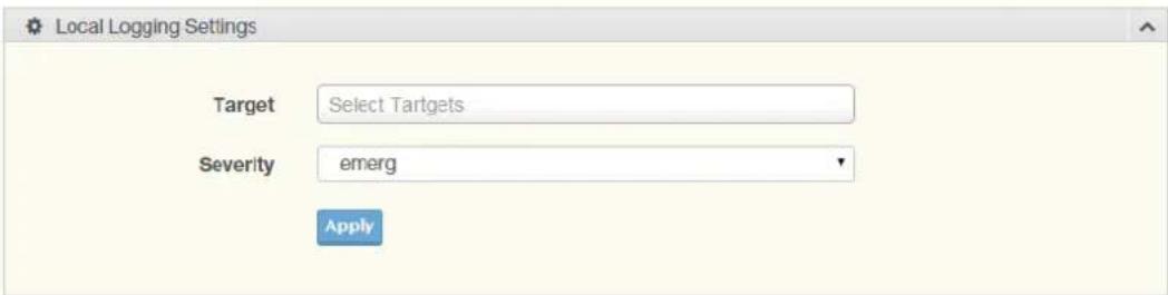
Figure 4.214 Diagnostics > System Log > Local Logging
The following table describes the items in the previous figure.
Item Description
Target Enter the local logging target.
Severity Click the drop-down menu to select the severity level for local log messages.
The level options are:
■ emerg: Indicates system is unusable. It is the highest level of severity
■ alert: Indicates action must be taken immediately
■ crit: Indicates critical conditions
■ error: Indicates error conditions
■ warning: Indicates warning conditions
notice: Indicates normal but significant conditions
■ info: Indicates informational messages
■ debug: Indicates debug-level messages
Apply Click Apply to save the values and update the screen.
The ensuing table for Local Logging Settings Status settings are informational only: Status, Target, Severity and Delete (click to delete the desired target).
4.10.4.3 System Log Server
The System Log Server page allows you to configure the log server.
To access this page, click Diagnostics > System Log > System Log Server.
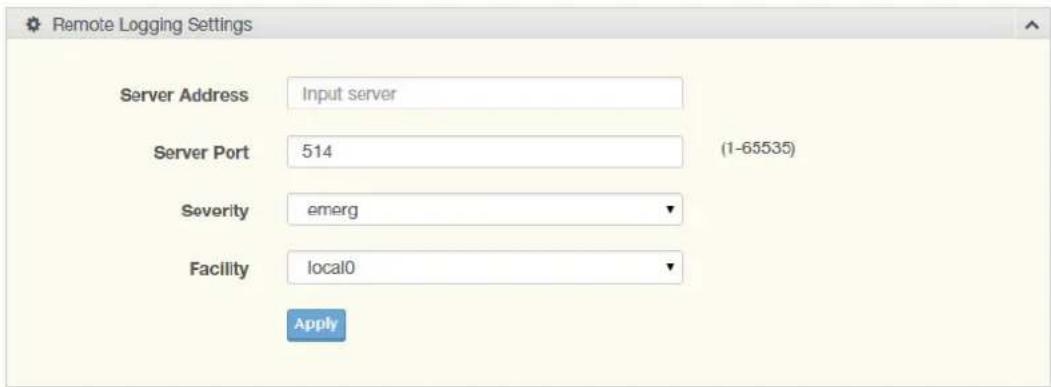
Figure 4.215 Diagnostics > System Log > System Log Server
The following table describes the items in the previous figure.
Item Description
Server Address Enter the IP address of the log server.
Server Port Enter the Udp port number of the log server.
Item Description
Severity Click the drop-down menu to select the severity level for local log messages. The default is emerg.
The level options are:
■ emerg: Indicates system is unusable. It is the highest level of severity
■ alert: Indicates action must be taken immediately
■ crit: Indicates critical conditions
■ error: Indicates error conditions
■ warning: Indicates warning conditions
■ notice: Indicates normal but significant conditions
■ info: Indicates informational messages
■ debug: Indicates debug-level messages
Facility Click the drop-down menu to select facility to which the message refers.
Apply Click Apply to save the values and update the screen.
The ensuing table for Remote Logging Setting Status settings are informational only: Status, Server Info, Severity, Facility and Delete (click to delete the desired server address).
4.10.5 DDM
The DDM page allows you to setup the diagnostic alarm status.
To access this page, click Diagnostics > DDM.
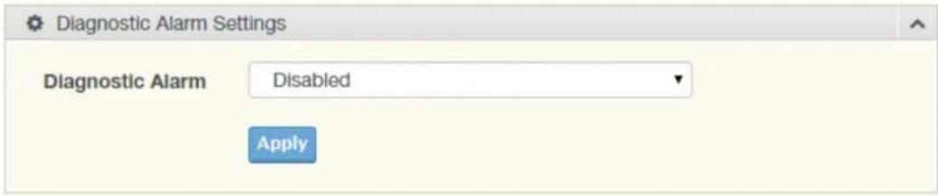
Figure 4.216 Diagnostics > DDM > Diagnostic Alarm Settings
The following table describes the items in the previous figure.
Item Description
Diagnostic Alarm Click the drop-down menu to designate the announcement method: Disabled, SysLog, E-mail, or SNMP.
Apply Click Apply to save the values and update the screen.
The ensuing table for Diagnostic Alarm Information settings are informational only: Diagnostic Alarm.
| GE17 | High Alarm | High Warning | Low Alarm | Low Warning | ||||
| Temperature 127℃~127℃ | 95.000 Enabled | ℃ Disabled | 90.000 Enabled | ℃ Disabled | -50.000 Enabled | ℃ Disabled | -45.000 Enabled | ℃ Disabled |
| Voltage 0.001~6V | 3.500 Enabled | V Disabled | 3.450 Enabled | V Disabled | 3.100 Enabled | V Disabled | 3.150 Enabled | V Disabled |
| TX Basis 1~121mA | 108.000 Enabled | mA Disabled | 90.000 Enabled | mA Disabled | 6.000 Enabled | mA Disabled | 7.000 Enabled | mA Disabled |
| TX Power 8~39dBm | -1.000 Enabled | dbm Disabled | -5.000 Enabled | dbm Disabled | -35.000 Enabled | dbm Disabled | -30.000 Enabled | dbm Disabled |
| RX Power 8~39dBm | -1.000 Enabled | dbm Disabled | -5.000 Enabled | dbm Disabled | -35.000 Enabled | dbm Disabled | -30.000 Enabled | dbm Disabled |
Figure 4.217 Diagnostics > DDM > DMI INFO
The following table describes the items in the previous figure.
Item Description
High Alarm Click Enabled or Disabled to set the alarm state.
High Warning Click Enabled or Disabled to set the alarm state.
Low Alarm Click Enabled or Disabled to set the alarm state.
Low Warning Click Enabled or Disabled to set the alarm state.
Apply Click Apply to save the values and update the screen.
The ensuing table for Vendor Info settings are informational only: Refresh (click to reload the vendor information), Port, Connector, Speed, VendorName, VendorOui, VendorPn, VendorRev, VendorSn and DateCode.
4.10.6 LED Indication
To access this page, click Diagnostics > LED Indication.
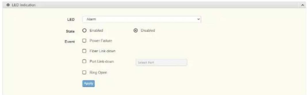
Figure 4.218 Diagnostics > LED Indication
The following table describes the items in the previous figure.
Item Description
LED Click the drop-down menu to select LED indicator.
State Select Enable or Disable to enable LED alarm.
Event Click to select the event of LED alarm.
Apply Click Apply to save the values and update the screen.
To access this page, click Diagnostics > LED Indication.
The following figure displays the LED Information settings.
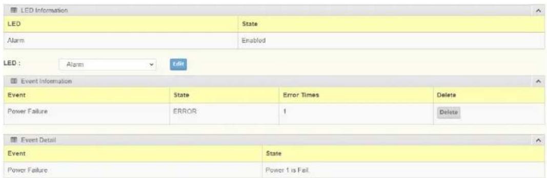
Figure 4.219 Diagnostics > LED Indication
4.11 Tools
4.11.1 IXM
The IXM tool is an industrial Ethernet switch solution to help the users deploy industrial Ethernet switch hardware by allowing users with multiple, managed Ethernet switches in the field to eliminate the need to individually connect to each device to configure it.
To access this page, click Tools > IXM.
Devices

Figure 4.220 Tools > IXM
The following table describes the items in the previous figure.
| Item Description | |
| Search Field Enter criteria to search the IXM information. | |
| # | Displays the reference to the device number. |
| Device Name | Displays the device name. |
| Device Model | Displays the device model type. |
| Category | Displays the device's category type. |
| IP Address | Displays the device's IP address. |
| MAC Address | Displays the device's IP MAC address. |
| Firmware Version | Displays the device's firmware version. |
| System Indicator | Displays the device's system indicator. |
| Previous | Click Previous to back to previous page. |
| Next Click Next to go to next page. | |
4.11.2 Backup Manager
The Backup Manager page allows you to configure a remote TFTP sever or host file system in order to backup the firmware image or configuration file.
To access this page, click Tools > Backup Manager.
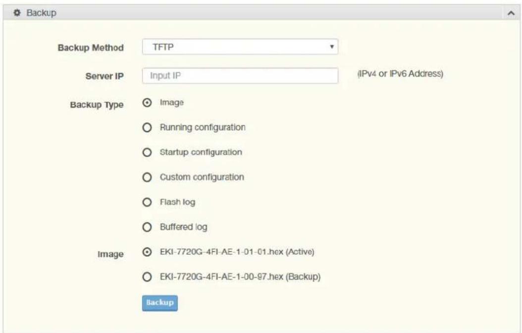
Figure 4.221 Tools > Backup Manager
The following table describes the items in the previous figure.
| Item Description |
| Backup Method Click the drop-down menu to select the backup method: TFTP or HTTP. |
| Server IP Enter the IP address of the backup server. |
| Backup Type Click a type to define the backup method: image: running configuration, startup configuration, custom configuration, flash log, or buffered log. |
| Image Click the format for the image type: Active or Backup. |
| Backup Click Backup to backup the settings. |
4.11.3 Upgrade Manager
The Upgrade Manager page allows you to configure a remote TFTP sever or host file system in order to upload firmware upgrade images or configuration files.
To access this page, click Tools > Upgrade Manager.
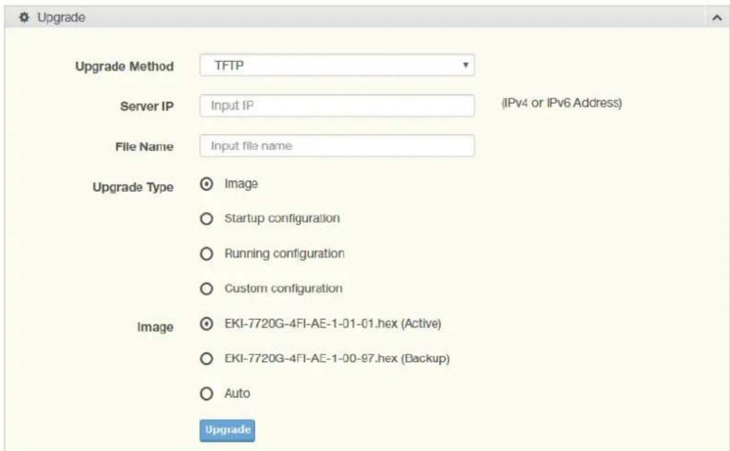
Figure 4.222 Tools > Upgrade Manager
The following table describes the items in the previous figure.
| Item Description |
| Upgrade Method Click the drop-down menu to select the upgrade method: TFTP or HTTP. |
| Server IP Enter the IP address of the upgrade server. |
| File Name Enter the file name of the new firmware version. |
| Upgrade Type Click a type to define the upgrade method: image, startup configuration, running configuration, or custom configuration. |
| Image Click the format for the image type: Active, Backup, or auto. |
| Upgrade Click Upgrade to upgrade to the current version. |
4.11.4 Dual Image
The Dual Image page allows you to setup an active and backup partitions for firmware image redundancy.
To access this page, click Tools > Dual Image.
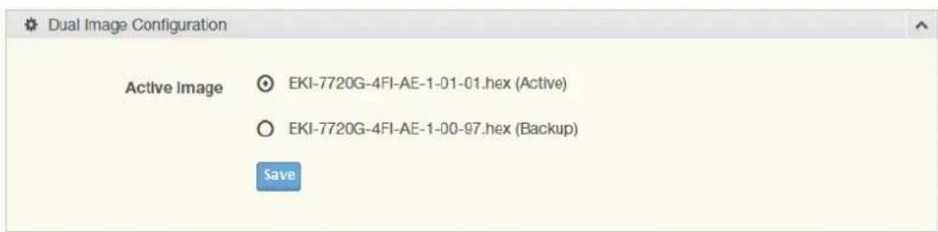
Figure 4.223 Tools > Dual Image
The following table describes the items in the previous figure.
| Item Description | |
| Active Image | Click the format for the image type: Active or Backup. |
| Save | Click Save to save and keep the new settings. |
The ensuing table for Image Information 0/1 settings are informational only: Flash Partition, Image Name, Image Size and Created Time.
4.11.5 Save Configuration
To access this page, click Tools > Save Configuration.
Click Save Configuration to FLASH to have configuration changes you have made to be saved across a system reboot. All changes submitted since the previous save or system reboot will be retained by the switch.
4.11.6 User Account
4.11.6.1 Add and Edit Users
The User Account page allows you to setup a user and the related parameters. To access this page, click Tools > User Account.
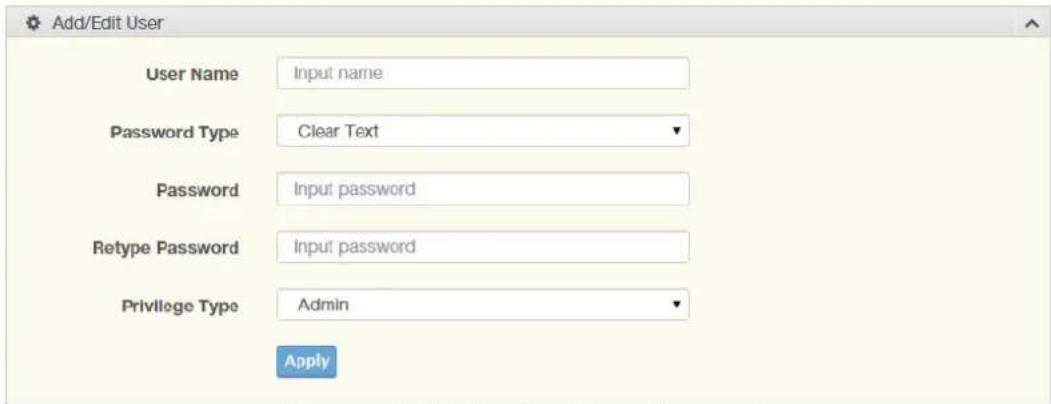
Figure 4.224 Tools > User Account
The following table describes the items in the previous figure.
| Item Description | |
| User Name Enter the name of the new user entry. | |
| Password Type | Click the drop-down menu to define the type of password: Clear Text, Encrypted or No Password. |
| Password Enter the character set for the define password type. | |
| Retype Password Retype the password entry to confirm the profile password. | |
| Privilege Type Click the drop-down menu to designate privilege authority for the user entry: Admin or User. | |
| Apply Click Apply to create a new user account. | |
4.11.6.2 Wrong Password
To access this page, click Tools > User Account.
The following figure displays the Wrong Password settings.

Figure 4.225 Tools > User Account
To access this page, click Tools > User Account.
Item Description
State Click to enable or disable the wrong password detection function.
Retry Time Enter a variable to designate the wrong password entry threshold, State option must be enabled.
Block Time Enter a variable to designate the lockout period in minutes after the retry attempts threshold is reached.
Apply Click Apply to create a new user account.
The following figure displays the Wrong Password Information settings.

Figure 4.226 Tools > User Account
4.11.7 N-Key
To access this page, click Tools > N-Key.

Figure 4.227 Tools > N-Key
The following table describes the items in the previous figure.
Item Description
Auto Mode Click the option to set the auto mode for the N-Key status.
N-Key Status Click the drop-down menu to select N-Key status.
Apply Click Apply to create a new user account.
To access this page, click Tools > N-Key.
The following figure displays the N-Key Information settings.
| N-Key Information | |
| Information Name | Information Value |
| Auto Mode | Enabled |
| N-Key Status | N-key is idle |
Figure 4.228 Tools > N-Key Information
4.11.8 Reset System
To access this page, click Tools > Reset System.
Click Restore to have all configuration parameters reset to their factory default values. All changes that have been made will be lost, even if you have issued a save.
Click Select Excepted Configuration to keep the configuration you selected when resetting.
Reset settings take effect after a system reboot.
4.11.9 Reboot Device
To access this page, click Tools > Reboot Device.
Click Reboot to reboot the switch. Any configuration changes you have made since the last time you issued a save will be lost.
The data map addresses of Advantech switches shown in the following table start from Modbus address 30001 for function code 4.
In the given example, the address offset 0x1000 (hex) equals Modbus address 34097, while the address offset 0x1100 (hex) equals Modbus address 34353.
The information given by the Advantech is shown in hex mode.
4.12.1 Modbus/TCP Mapping Table
| Catalog Name Data Type Interpretation Address | Offset (Hex) | Address 3X | Description | ||||
| System Info Vendor ID = 0x'13FE | 1 word 16 bits HEX 0x0000 30001 Vendor ID = 0x13FE | ||||||
| Unit ID = 0xFF 1 word 16 bits HEX 0x0001 30002 Unit ID = 0xFF | |||||||
| Product Code 1 word 16 bits HEX 0x0002 30003 Product Code | |||||||
| Vendor Name = "Advantech" | 16 words | 32 chars | ASCII | 0x0010 30017 Vendor Name = | |||
| "Advantech"Word 0 Hi byte = 'A'Word 0 Lo byte = 'd'Word 1 Hi byte = 'v'Word 1 Lo byte = 'a'Word 2 Hi byte = 'n'Word 2 Lo byte = 't'Word 3 Hi byte = 'e'Word 3 Lo byte = 'c'Word 4 Hi byte = 'h'Word 4 Lo byte = '\0' | |||||||
| Product Name = "EKI-xxxx" | 16 words | 32 chars | ASCII | 0x0020 30033 Product Name = | |||
| "EKI-xxxx"Word 0 Hi byte = 'E'Word 0 Lo byte = 'K'Word 1 Hi byte = 'l'Word 1 Lo byte = '-'Word 2 Hi byte = 'x'Word 2 Lo byte = 'x'Word 3 Hi byte = 'x'Word 3 Lo byte = 'x'Word 4 Hi byte = '\0' | |||||||
| Firmware Version | 2 words | 32 bits HEX 0x020A | 30523 Firmware Version | ||||
| Ethernet MAC Address | 3 words | 48 bits HEX 0x020E | 30527 Ethernet MAC | ||||
| Catalog | Name | Data Type | Interpretation | Address Offset (Hex) | Address 3X | Description | |
| System Info Revision Number | 16 words | 32 chars | ASCII 0x0211 30530 | Product Name = | |||
| "YYY.xxxxx"Word 0 Hi byte = 'Y'Word 0 Lo byte = 'Y'Word 1 Hi byte = 'Y'Word 1 Lo byte = '.'Word 2 Hi byte = 'x'Word 2 Lo byte = 'x'Word 3 Hi byte = 'x'Word 3 Lo byte = 'x'Word 4 Hi byte = 'x'Word 4 Hi byte = '\0' | |||||||
| IP Address 2 words | 32 bits HEX 0x0400 31025 | IP Address | Ex: IP = 192.168.1.1Word 0 Hi byte = 0xC0Word 0 Lo byte = 0xA8Word 1 Hi byte = 0x01Word 1 Lo byte = 0x01 | ||||
| Port Info Port Status 1 word 16 bits HEX 0x1000 ~ | 0x101F | 34097 ~ 34128 | Port Status0x0000: Link down0x0001: Link up0xFFFF: No port | ||||
| 34107 | |||||||
| 34108 | |||||||
| 34109 | |||||||
| 34110 | |||||||
| 34111 | |||||||
| 34112 | |||||||
| 34113 | |||||||
| 34114 | |||||||
| 34115 | |||||||
| 34116 | |||||||
| 34117 | |||||||
| 34118 | |||||||
| 34119 | |||||||
| 34120 | |||||||
| 34121 | |||||||
| 34122 | |||||||
| 34123 | |||||||
| 34124 | |||||||
| 34125 | |||||||
| 34126 | |||||||
| 34127 | |||||||
| 34128 | |||||||
| Port Info Port Speed 1 word 16 bits HEX 0x1100 ~ | 0x111F | 34353 ~ 34384 | Port Speed 0x0000: 10M-Half 0x0001: 10M-Full 0x0002: 100M-Half 0x0003: 100M-Full 0x0004: 1000M-Half 0x0005: 1000M-Full 0xFFFF: No port | ||||
| Catalog Name | Data Type | Interpretation Address | Offset (Hex) | Address 3X | Description |
| Port Info Port 7 Flow | 1 word 16 bits HEX 0x1206 34615 | ||||
| Control | |||||
| Port 8 Flow Control | 1 word 16 bits HEX 0x1207 34616 | ||||
| Port 9 Flow Control | 1 word 16 bits HEX 0x1208 34617 | ||||
| Port 10 Flow Control | 1 word 16 bits HEX 0x1209 34618 | ||||
| Port 11 Flow Control | 1 word 16 bits HEX 0x120A 34619 | ||||
| Port 12 Flow Control | 1 word 16 bits HEX 0x120B 34620 | ||||
| Port 13 Flow Control | 1 word 16 bits HEX 0x120C 34621 | ||||
| Port 14 Flow Control | 1 word 16 bits HEX 0x120D 34622 | ||||
| Port 15 Flow Control | 1 word 16 bits HEX 0x120E 34623 | ||||
| Port 16 Flow Control | 1 word 16 bits HEX 0x120F 34624 | ||||
| Port 17 Flow Control | 1 word 16 bits HEX 0x1210 34625 | ||||
| Port 18 Flow Control | 1 word 16 bits HEX 0x1211 34626 | ||||
| Port 19 Flow Control | 1 word 16 bits HEX 0x1212 34627 | ||||
| Port 20 Flow Control | 1 word 16 bits HEX 0x1213 34628 | ||||
| Port 21 Flow Control | 1 word 16 bits HEX 0x1214 34629 | ||||
| Port 22 Flow Control | 1 word 16 bits HEX 0x1215 34630 | ||||
| Port 23 Flow Control | 1 word 16 bits HEX 0x1216 34631 | ||||
| Port 24 Flow Control | 1 word 16 bits HEX 0x1217 34632 | ||||
| Port 25 Flow Control | 1 word 16 bits HEX 0x1218 34633 | ||||
| Port 26 Flow Control | 1 word 16 bits HEX 0x1219 34634 | ||||
| Port 27 Flow Control | 1 word 16 bits HEX 0x121A 34635 | ||||
| Port 28 Flow Control | 1 word 16 bits HEX 0x121B 34636 | ||||
| Port 29 Flow Control | 1 word 16 bits HEX 0x121C 34637 | ||||
| Port 30 Flow Control | 1 word 16 bits HEX 0x121D 34638 | ||||
| Port 31 Flow Control | 1 word 16 bits HEX 0x121E 34639 | ||||
| Port 32 Flow Control | 1 word 16 bits HEX 0x121F 34640 | ||||
| Catalog Name Data Type Interpretation Address | Offset (Hex) | Address 3X | Description | |||
| Port Info Port Descrip-tion | 20 words | 40 chars | ASCII 0x1400 ~ | 0x166C | 35121 ~ 35741 | Port Description Port Description = "100RX,RJ45." Word 0 Hi byte = '1' Word 0 Lo byte = '0' Word 1Hi byte = '0' Word 1 Lo byte = 'R' Word 2 Hi byte = 'X' Word 2 Lo byte = ', Word 3 Hi byte = 'R' Word 3 Lo byte = 'J' Word 4 Hi byte = '4' Word 4 Lo byte = '5' Word 5 Hi byte = '.' Word 5 Lo byte = '\0' |
| Port 1 Description | 20 words | 40 chars | ASCII 0x1400 35121 | |||
| Port 2 Description | 20 words | 40 chars | ASCII 0x1414 35141 | |||
| Port 3 Description | 20 words | 40 chars | ASCII 0x1428 35161 | |||
| Port 4 Description | 20 words | 40 chars | ASCII 0x143C 35181 | |||
| Port 5 Description | 20 words | 40 chars | ASCII 0x1450 35201 | |||
| Port 6 Description | 20 words | 40 chars | ASCII 0x1464 35221 | |||
| Port 7 Description | 20 words | 40 chars | ASCII 0x1478 35241 | |||
| Port 8 Description | 20 words | 40 chars | ASCII 0x148C 35261 | |||
| Port 9 Description | 20 words | 40 chars | ASCII 0x14A0 35281 | |||
| Port 10 Description | 20 words | 40 chars | ASCII 0x14B4 35301 | |||
| Port 11 Description | 20 words | 40 chars | ASCII 0x14C8 35321 | |||
| Port 12 Description | 20 words | 40 chars | ASCII 0x14DC 35341 | |||
| Port 13 Description | 20 words | 40 chars | ASCII 0x14F0 35361 | |||
| Port 14 Description | 20 words | 40 chars | ASCII 0x1504 35381 | |||
| Port 15 Description | 20 words | 40 chars | ASCII 0x1518 35401 | |||
| Port 16 Description | 20 words | 40 chars | ASCII 0x152C 35421 | |||
| Port 17 Description | 20 words | 40 chars | ASCII 0x1540 35441 | |||
| Port 18 Description | 20 words | 40 chars | ASCII 0x1554 35461 | |||
| Port 19 Description | 20 words | 40 chars | ASCII 0x1568 35481 | |||
| Port 20 Description | 20 words | 40 chars | ASCII 0x157C 35501 | |||
| Port 21 Description | 20 words | 40 chars | ASCII 0x1590 35521 | |||
| Port 22 Description | 20 words | 40 chars | ASCII 0x15A4 35541 | |||
| Port 23 Description | 20 words | 40 chars | ASCII 0x15B8 35561 | |||
| Catalog Name Data Type | Interpretation | Address | Offset (Hex) | Address 3X | Description | ||
| Port Info Port 24 | 20 words | 40 chars | ASCII 0x15CC 35581 | ||||
| Description | |||||||
| Port 25 Description | 20 words | 40 chars | ASCII 0x15E0 35601 | ||||
| Port 26 Description | 20 words | 40 chars | ASCII 0x15F4 35621 | ||||
| Port 27 Description | 20 words | 40 chars | ASCII 0x1608 35641 | ||||
| Port 28 Description | 20 words | 40 chars | ASCII 0x161C 35661 | ||||
| Port 29 Description | 20 words | 40 chars | ASCII 0x1630 35681 | ||||
| Port 30 Description | 20 words | 40 chars | ASCII 0x1644 35701 | ||||
| Port 31 Description | 20 words | 40 chars | ASCII 0x1658 35721 | ||||
| Port 32 Description | 20 words | 40 chars | ASCII 0x166C 35741 | ||||
| Link Up Counter | 1 word | 16 bits HEX 0x1700 ~ | 0x171F | 35889 ~ 35920 | Link Up Counter Ex: port link up coun- ter = 13 Received MODBUS response: 0x000D | ||
| Port 1 Link Up Counter | 1 word | 16 bits HEX 0x1700 35889 | |||||
| Port 2 Link Up Counter | 1 word | 16 bits HEX 0x1701 35890 | |||||
| Port 3 Link Up Counter | 1 word | 16 bits HEX 0x1702 35891 | |||||
| Port 4 Link Up Counter | 1 word | 16 bits HEX 0x1703 35892 | |||||
| Port 5 Link Up Counter | 1 word | 16 bits HEX 0x1704 35893 | |||||
| Port 6 Link Up Counter | 1 word | 16 bits HEX 0x1705 35894 | |||||
| Port 7 Link Up Counter | 1 word | 16 bits HEX 0x1706 35895 | |||||
| Port 8 Link Up Counter | 1 word | 16 bits HEX 0x1707 35896 | |||||
| Port 9 Link Up Counter | 1 word | 16 bits HEX 0x1708 35897 | |||||
| Port 10 Link Up Counter | 1 word | 16 bits HEX 0x1709 35898 | |||||
| Port 11 Link Up Counter | 1 word | 16 bits HEX 0x170A 35899 | |||||
| Port 12 Link Up Counter | 1 word | 16 bits HEX 0x170B 35900 | |||||
| Port 13 Link Up Counter | 1 word | 16 bits HEX 0x170C 35901 | |||||
| Port 14 Link Up Counter | 1 word | 16 bits HEX 0x170D 35902 | |||||
| Port 15 Link Up Counter | 1 word | 16 bits HEX 0x170E 35903 | |||||
| Port 16 Link Up Counter | 1 word | 16 bits HEX 0x170F 35904 | |||||
| Port 17 Link Up Counter | 1 word | 16 bits HEX 0x1710 35905 | |||||
| Port 18 Link Up Counter | 1 word | 16 bits HEX 0x1711 35906 | |||||
| Port 19 Link Up Counter | 1 word | 16 bits HEX 0x1712 35907 | |||||
| Catalog Name Data Type Interpretation Address | Offset (Hex) | Address 3X | Description | ||||
| Port Info Port 20 Link | Up Counter | 1 word | 16 bits HEX 0x1713 35908 | ||||
| Port 21 Link Up Counter | 1 word | 16 bits HEX 0x1714 35909 | |||||
| Port 22 Link Up Counter | 1 word | 16 bits HEX 0x1715 35910 | |||||
| Port 23 Link Up Counter | 1 word | 16 bits HEX 0x1716 35911 | |||||
| Port 24 Link Up Counter | 1 word | 16 bits HEX 0x1717 35912 | |||||
| Port 25 Link Up Counter | 1 word | 16 bits HEX 0x1718 35913 | |||||
| Port 26 Link Up Counter | 1 word | 16 bits HEX 0x1719 35914 | |||||
| Port 27 Link Up Counter | 1 word | 16 bits HEX 0x171A 35915 | |||||
| Port 28 Link Up Counter | 1 word | 16 bits HEX 0x171B 35916 | |||||
| Port 29 Link Up Counter | 1 word | 16 bits HEX 0x171C 35917 | |||||
| Port 30 Link Up Counter | 1 word | 16 bits HEX 0x171D 35918 | |||||
| Port 31 Link Up Counter | 1 word | 16 bits HEX 0x171E 35919 | |||||
| Port 32 Link Up Counter | 1 word | 16 bits HEX 0x171F 35920 | |||||
| Packet Info Tx Packets Counter | 4 words | 64 bits HEX 0x2000 ~ | 0x207C | 38193 ~ 38317 | Tx Packets Ex: port 1 Tx Packet Amount = 11223344 Received MODBUS response: 0xAB4130 Word 0 = 0x0000 Word 1 = 0x0000 Word 2 = 0x00AB Word 3 = 0x4130 | ||
| Packet Info Port 14 Tx Packets | 4 words | 64 bits HEX 0x2034 38245 | |||||
| Port 15 Tx Packets | 4 words | 64 bits HEX 0x2038 38249 | |||||
| Port 16 Tx Packets | 4 words | 64 bits HEX 0x203C 38253 | |||||
| Port 17 Tx Packets | 4 words | 64 bits HEX 0x2040 38257 | |||||
| Port 18 Tx Packets | 4 words | 64 bits HEX 0x2044 38261 | |||||
| Port 19 Tx Packets | 4 words | 64 bits HEX 0x2048 38265 | |||||
| Port 20 Tx Packets | 4 words | 64 bits HEX 0x204C 38269 | |||||
| Port 21 Tx Packets | 4 words | 64 bits HEX 0x2050 38273 | |||||
| Port 22 Tx Packets | 4 words | 64 bits HEX 0x2054 38277 | |||||
| Port 23 Tx Packets | 4 words | 64 bits HEX 0x2058 38281 | |||||
| Port 24 Tx Packets | 4 words | 64 bits HEX 0x205C 38285 | |||||
| Port 25 Tx Packets | 4 words | 64 bits HEX 0x2060 38289 | |||||
| Port 26 Tx Packets | 4 words | 64 bits HEX 0x2064 38293 | |||||
| Port 27 Tx Packets | 4 words | 64 bits HEX 0x2068 38297 | |||||
| Port 28 Tx Packets | 4 words | 64 bits HEX 0x206C 38301 | |||||
| Port 29 Tx Packets | 4 words | 64 bits HEX 0x2070 38305 | |||||
| Port 30 Tx Packets | 4 words | 64 bits HEX 0x2074 38309 | |||||
| Port 31 Tx Packets | 4 words | 64 bits HEX 0x2078 38313 | |||||
| Port 32 Tx Packets | 4 words | 64 bits HEX 0x207C 38317 | |||||
| Rx Packets Counter | 4 words | 64 bits HEX 0x2100 | ~0x217C | 38449 ~ 38573 | Rx Packets Ex: port 1 Rx Packet Amount = 11223344 Received MODBUS response: 0xAB4130 Word 0 = 0x0000 Word 1 = 0x0000 Word 2 = 0x00AB Word 3 = 0x4130 | ||
| Port 1 Rx Packets | 4 words | 64 bits HEX 0x2100 38449 | |||||
| Port 2 Rx Packets | 4 words | 64 bits HEX 0x2104 38453 | |||||
| Port 3 Rx Packets | 4 words | 64 bits HEX 0x2108 38457 | |||||
| Port 4 Rx Packets | 4 words | 64 bits HEX 0x210C 38461 | |||||
| Port 5 Rx Packets | 4 words | 64 bits HEX 0x2110 38465 | |||||
| Port 6 Rx Packets | 4 words | 64 bits HEX 0x2114 38469 | |||||
| Port 7 Rx Packets | 4 words | 64 bits HEX 0x2118 38473 | |||||
| Packet Info Port 8 Rx | 4 packets | words | 64 bits HEX 0x211C 38477 | ||||
| Port 9 Rx Packets | 4 words | 64 bits HEX 0x2120 38481 | |||||
| Port 10 Rx Packets | 4 words | 64 bits HEX 0x2124 38485 | |||||
| Port 11 Rx Packets | 4 words | 64 bits HEX 0x2128 38489 | |||||
| Port 12 Rx Packets | 4 words | 64 bits HEX 0x212C 38493 | |||||
| Port 13 Rx Packets | 4 words | 64 bits HEX 0x2130 38497 | |||||
| Port 14 Rx Packets | 4 words | 64 bits HEX 0x2134 38501 | |||||
| Port 15 Rx Packets | 4 words | 64 bits HEX 0x2138 38505 | |||||
| Port 16 Rx Packets | 4 words | 64 bits HEX 0x213C 38509 | |||||
| Port 17 Rx Packets | 4 words | 64 bits HEX 0x2140 38513 | |||||
| Port 18 Rx Packets | 4 words | 64 bits HEX 0x2144 38517 | |||||
| Port 19 Rx Packets | 4 words | 64 bits HEX 0x2148 38521 | |||||
| Port 20 Rx Packets | 4 words | 64 bits HEX 0x214C 38525 | |||||
| Port 21 Rx Packets | 4 words | 64 bits HEX 0x2150 38529 | |||||
| Port 22 Rx Packets | 4 words | 64 bits HEX 0x2154 38533 | |||||
| Port 23 Rx Packets | 4 words | 64 bits HEX 0x2158 38537 | |||||
| Port 24 Rx Packets | 4 words | 64 bits HEX 0x215C 38541 | |||||
| Port 25 Rx Packets | 4 words | 64 bits HEX 0x2160 38545 | |||||
| Port 26 Rx Packets | 4 words | 64 bits HEX 0x2164 38549 | |||||
| Port 27 Rx Packets | 4 words | 64 bits HEX 0x2168 38553 | |||||
| Port 28 Rx Packets | 4 words | 64 bits HEX 0x216C 38557 | |||||
| Port 29 Rx Packets | 4 words | 64 bits HEX 0x2170 38561 | |||||
| Port 30 Rx Packets | 4 words | 64 bits HEX 0x2174 38565 | |||||
| Port 31 Rx Packets | 4 words | 64 bits HEX 0x2178 38569 | |||||
| Port 32 Rx Packets | 4 words | 64 bits HEX 0x217C 38573 | |||||
| Tx Error Pack-ets Counter | 2 words | 32 bits HEX 0x2200 ~ | 0x223E | 38705 ~ 38767 | Tx Error Packets Ex: port 1 Tx Packet Amount = 11223344 Received MODBUS response: 0xAB4130 Word 0 = 0x00AB Word 1 = 0x4130 | ||
| Port 1 Tx Error Packets | 2 words | 32 bits HEX 0x2200 38705 | |||||
| Port 2 Tx Error Packets | 2 words | 32 bits HEX 0x2202 38707 | |||||
| Packet Info Port 3 Tx Error Packets | 2 words | 32 bits HEX 0x2204 38709 | |||||
| Port 4 Tx Error Packets | 2 words | 32 bits HEX 0x2206 38711 | |||||
| Port 5 Tx Error Packets | 2 words | 32 bits HEX 0x2208 38713 | |||||
| Port 6 Tx Error Packets | 2 words | 32 bits HEX 0x220A 38715 | |||||
| Port 7 Tx Error Packets | 2 words | 32 bits HEX 0x220C 38717 | |||||
| Port 8 Tx Error Packets | 2 words | 32 bits HEX 0x220E 38719 | |||||
| Port 9 Tx Error Packets | 2 words | 32 bits HEX 0x2210 38721 | |||||
| Port 10 Tx Error Packets | 2 words | 32 bits HEX 0x2212 38723 | |||||
| Port 11 Tx Error Packets | 2 words | 32 bits HEX 0x2214 38725 | |||||
| Port 12 Tx Error Packets | 2 words | 32 bits HEX 0x2216 38727 | |||||
| Port 13 Tx Error Packets | 2 words | 32 bits HEX 0x2218 38729 | |||||
| Port 14 Tx Error Packets | 2 words | 32 bits HEX 0x221A 38731 | |||||
| Port 15 Tx Error Packets | 2 words | 32 bits HEX 0x221C 38733 | |||||
| Port 16 Tx Error Packets | 2 words | 32 bits HEX 0x221E 38735 | |||||
| Port 17 Tx Error Packets | 2 words | 32 bits HEX 0x2220 38737 | |||||
| Port 18 Tx Error Packets | 2 words | 32 bits HEX 0x2222 38739 | |||||
| Port 19 Tx Error Packets | 2 words | 32 bits HEX 0x2224 38741 | |||||
| Port 20 Tx Error Packets | 2 words | 32 bits HEX 0x2226 38743 | |||||
| Port 21 Tx Error Packets | 2 words | 32 bits HEX 0x2228 38745 | |||||
| Port 22 Tx Error Packets | 2 words | 32 bits HEX 0x222A 38747 | |||||
| Port 23 Tx Error Packets | 2 words | 32 bits HEX 0x222C 38749 | |||||
| Port 24 Tx Error Packets | 2 words | 32 bits HEX 0x222E 38751 | |||||
| Port 25 Tx Error Packets | 2 words | 32 bits HEX 0x2230 38753 | |||||
| Port 26 Tx Error Packets | 2 words | 32 bits HEX 0x2232 38755 | |||||
| Port 27 Tx Error Packets | 2 words | 32 bits HEX 0x2234 38757 | |||||
| Port 28 Tx Error Packets | 2 words | 32 bits HEX 0x2236 38759 | |||||
| Port 29 Tx Error Packets | 2 words | 32 bits HEX 0x2238 38761 | |||||
| Port 30 Tx Error Packets | 2 words | 32 bits HEX 0x223A 38763 | |||||
| Port 31 Tx Error Packets | 2 words | 32 bits HEX 0x223C 38765 | |||||
| Port 32 Tx Error Packets | 2 words | 32 bits HEX 0x223E 38767 | |||||
| Catalog Name Data Type Interpretation Address | Offset (Hex) | Address 3X | Description | ||
| Packet Info Rx Error Pack-ets Counter | 2 words | 32 bits HEX 0x2300 ~ | 0x233E | 38961 ~ 39023 | Rx Error PacketsEx: port 1 Rx PacketAmount = 11223344Received MODBUSresponse: 0xAB4130Word 0 = 0x00ABWord 1 = 0x4130 |
| Port 1 RxError Packets | 2 words | 32 bits HEX 0x2300 38961 | |||
| Port 2 RxError Packets | 2 words | 32 bits HEX 0x2302 38963 | |||
| Port 3 RxError Packets | 2 words | 32 bits HEX 0x2304 38965 | |||
| Port 4 RxError Packets | 2 words | 32 bits HEX 0x2306 38967 | |||
| Port 5 RxError Packets | 2 words | 32 bits HEX 0x2308 38969 | |||
| Port 6 RxError Packets | 2 words | 32 bits HEX 0x230A 38971 | |||
| Port 7 RxError Packets | 2 words | 32 bits HEX 0x230C 38973 | |||
| Port 8 RxError Packets | 2 words | 32 bits HEX 0x230E 38975 | |||
| Port 9 RxError Packets | 2 words | 32 bits HEX 0x2310 38977 | |||
| Port 10 RxError Packets | 2 words | 32 bits HEX 0x2312 38979 | |||
| Port 11 RxError Packets | 2 words | 32 bits HEX 0x2314 38981 | |||
| Port 12 RxError Packets | 2 words | 32 bits HEX 0x2316 38983 | |||
| Port 13 RxError Packets | 2 words | 32 bits HEX 0x2318 38985 | |||
| Port 14 RxError Packets | 2 words | 32 bits HEX 0x231A 38987 | |||
| Port 15 RxError Packets | 2 words | 32 bits HEX 0x231C 38989 | |||
| Port 16 RxError Packets | 2 words | 32 bits HEX 0x231E 38991 | |||
| Port 17 RxError Packets | 2 words | 32 bits HEX 0x2320 38993 | |||
| Port 18 RxError Packets | 2 words | 32 bits HEX 0x2322 38995 | |||
| Port 19 RxError Packets | 2 words | 32 bits HEX 0x2324 38997 | |||
| Port 20 RxError Packets | 2 words | 32 bits HEX 0x2326 38999 | |||
| Port 21 RxError Packets | 2 words | 32 bits HEX 0x2328 39001 | |||
| Port 22 RxError Packets | 2 words | 32 bits HEX 0x232A 39003 | |||
| Port 23 RxError Packets | 2 words | 32 bits HEX 0x232C 39005 | |||
| Port 24 RxError Packets | 2 words | 32 bits HEX 0x232E 39007 | |||
| Port 25 RxError Packets | 2 words | 32 bits HEX 0x2330 39009 | |||
| Port 26 RxError Packets | 2 words | 32 bits HEX 0x2332 39011 | |||
| Port 27 RxError Packets | 2 words | 32 bits HEX 0x2334 39013 | |||
| Catalog Name Data Type Interpretation Address | Offset (Hex) | Address 3X | Description | |||
| Packet Info Port 28 Rx | Error Packets | 2 words | 32 bits HEX 0x2336 39015 | |||
| Port 29 Rx | 2 words | 32 bits HEX 0x2338 39017 | ||||
| Error Packets | ||||||
| Port 30 Rx | 2 words | 32 bits HEX 0x233A 39019 | ||||
| Error Packets | ||||||
| Port 31 Rx | 2 words | 32 bits HEX 0x233C 39021 | ||||
| Error Packets | ||||||
| Port 32 Rx | 2 words | 32 bits HEX 0x233E 39023 | ||||
| Error Packets | ||||||
Chapter
5
Troubleshooting
5.1 Troubleshooting
- Verify that the device is using the right DC power cord/adapter, or the device may be damaged.
- Select the proper UTP/STP cable to construct the user network. Use unshielded twisted-pair (UTP) or shield twisted-pair (STP) cable for RJ-45 connections that depend on the connector type the switch equipped: 100R Category 3, 4 or 5 cable for 10Mbps connections, 100R Category 5 cable for 100Mbps connections, or 100R Category 5e/above cable for 1000Mbps connections. Also be sure that the length of any twisted-pair connection does not exceed 100 meters (328 feet).
R = replacement letter for Ohm symbol.
Diagnosing LED Indicators: To assist in identifying problems, the switch can be easily monitored through panel indicators, which describe common problems the user may encounter, so the user can be guided towards possible solutions.
If the power indicator does not light on when the power cord is plugged in, you may have a problem with power cord. Check for loose power connections, power losses, or surges, at the power outlet. If you still cannot resolve the problem, contact a local dealer for assistance.
If the LED indicators are normal and the connected cables are correct but packets still cannot be transmitted, please check the user system's Ethernet device configuration or status.
ADVANTECH
Enabling an Intelligent Planet
www.advantech.com
Please verify specifications before quoting. This guide is intended for reference purposes only.
All product specifications are subject to change without notice.
No part of this publication may be reproduced in any form or by any means, electronic, photocopying, recording or otherwise, without prior written permission of the publisher.
All brand and product names are trademarks or registered trademarks of their respective companies.
© Advantech Co., Ltd. 2021
- EKI-7720 Series
- Copyright
- Acknowledgements
- Product Warranty (5 years)
- Declaration of Conformity
- CE
- FCC Class A
- Technical Support and Assistance
- Warnings, Cautions and Notes
- Document Feedback
- Packing List
- Safety Instructions
- Safety Precaution - Static Electricity
- Contents
- Chapter 1 Product Overview ......1
- Chapter 2 Switch Installation ......7
- Chapter 3 Configuration Utility ......22
- Chapter 4 Managing Switch ......28
- Monitoring 30
- System 38
- L2 Switching.... 45
- MAC Address Table 77
- Security 79
- QoS 100
- Management 111
- Chapter 5 Troubleshooting.... 158
- List of Figures
- Chapter 1
- Specifications
- Hardware Views
- Front View
- System LED Panel
- No. LED Name LED Color Description
- Rear View
- Top View
- No. Item Description
- Dimensions
- Chapter 2
- Installation Guidelines
- Connecting Hardware
- Verifying Switch Operation
- Installing the Switch
- DIN Rail Mounting
- Installing the DIN-Rail Mounting Kit
- Removing the DIN-Rail Mounting Kit
- Wall-Mounting
- Installing and Removing SFP Modules
- Installing SFP Modules
- Removing SFP Modules
- Connecting the Switch to Ethernet Ports
- RJ45 Ethernet Cable Wiring
- Connecting the Switch to Console Port
- Power Supply Installation
- Overview
- Considerations
- Grounding the Device
- Wiring a Relay Contact
- Wiring the Power Inputs
- Caution!
- Warning!
- Reset Button
- Chapter 3
- Configuration Utility
- First Time Setup
- Overview
- Introduction
- Administrative Interface Access
- Using the Graphical (Web) Interface
- Configuring the Switch for Network Access
- Configuring the Ethernet Ports
- Command Line Interface Configuration
- Introduction to Command-Line Interface (CLI)
- Accessing the CLI
- Web Browser Configuration
- Preparing for Web Configuration
- System Login
- Chapter 4
- Log In
- Recommended Practices
- Changing Default Password
- Monitoring
- Device Information
- Logging Message
- Port Monitoring
- Port Statistics
- Port Utilization
- Item Description
- Port Error Disable
- Link Aggregation
- LLDP Statistics
- IGMP Statistics
- MLD Statistics
- System
- IP Settings
- IPv6 Settings
- DHCP Client Option 82
- DHCP Auto Provision
- Management VLAN
- System Time
- Network Port
- L2 Switching
- Port Configuration
- Port Mirror
- Link Aggregation
- Load Balance
- LAG Port Settings
- LACP Priority Settings
- LACP Port Settings
- 802.1Q VLAN
- VLAN Management
- PVID Settings
- Port to VLAN
- RSPAN VLAN
- Q-in-Q
- Global Settings
- Port Settings
- GARP
- GARP Settings
- GVRP Settings
- GMRP Settings
- 802.3az EEE
- Multicast
- Multicast Filtering
- IGMP Snooping
- IGMP Settings
- IGMP Querier
- Multicast Groups
- MLD Snooping
- MLD Settings
- MLD Querier
- MLD Static Group
- Router Ports
- Jumbo Frame
- Spanning Tree
- STP Global Settings
- STP Port Settings
- STP Bridge Settings
- STP Port Advanced Settings
- MST Config Identification
- MST ID Settings
- MSTI Priority Settings
- MSTI Bridge Info
- MSTI Port Advanced settings
- STP Statistics
- X-Ring Elite
- X-Ring Elite Settings
- X-Ring Elite Groups
- X-Ring Pro
- X-Ring Pro Settings
- X-Ring Pro Groups
- Loopback Detection
- Global Settings
- Port Settings
- ERPS
- ERPS Settings
- ERPS Groups
- MAC Address Table
- Static MAC
- MAC Aging Time
- Dynamic Forwarding Table
- Security
- Storm Control
- Global Settings
- Port Settings
- Port Security
- Protected Ports
- DoS Prevention
- DoS Global Settings
- DoS Port Settings
- Applications
- TELNET
- SSH
- HTTP
- HTTPS
- 802.1x
- 802.1x Global Settings
- 802.1x Port Configuration
- IP Security
- Global Settings
- Entry Settings
- Security Login
- Global Settings
- Access Control Settings
- Access Control List
- MAC ACL
- Entry List
- IP ACL
- Entry Settings
- IP Source Guard
- Global Settings
- Entry Settings
- DHCP Snooping
- Global Settings
- Entry Settings
- ARP Spoofing
- QoS
- General
- QoS Properties
- QoS Settings
- Queue Scheduling
- CoS Mapping
- DSCP Mapping
- QoS Basic Mode
- Global Settings
- Port Settings
- Rate Limit
- Ingress Bandwidth Control
- Egress Bandwidth Control
- Egress Queue
- Bandwidth Guarantee
- Global Settings
- Utilization
- Management
- LLDP
- LLDP System Settings
- LLDP Port Settings
- LLDP Local Device Info
- LLDP Remote Device Info
- LLDP Overloading
- SNMP
- SNMP Settings
- SNMP Community
- SNMPv3 EngineID
- SNMPv3 Settings
- SNMP Trap
- Power Over Ethernet
- PoE System Settings
- PoE Port Settings
- TCP Modbus Settings
- TCP Modbus Settings
- DHCP Server
- Status Settings
- Global Settings
- Port Settings
- Option 82 Settings
- Client MAC Settings
- Lease Entry
- SMTP Client
- Global Settings
- Profile Settings
- Sending Message
- RMON
- RMON Statistics
- RMON History
- RMON Alarm
- RMON Event
- NTP Server
- Diagnostics
- Cable Diagnostics
- Ping Test
- IPv6 Ping Test
- System Log
- Logging Service
- Local Logging
- System Log Server
- DDM
- LED Indication
- Tools
- IXM
- Device Name Device Model Category IP Address MAC Address Firmware Version System Indicator
- Backup Manager
- Upgrade Manager
- Dual Image
- Save Configuration
- User Account
- Add and Edit Users
- Wrong Password
- N-Key
- Reset System
- Reboot Device
- Modbus/TCP Mapping Table
- Chapter
- 5
- Troubleshooting
- Troubleshooting
- ADVANTECH
Brand : Advantech
Model : EKI-7720E-4FI-AE
Category : Switch