
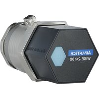
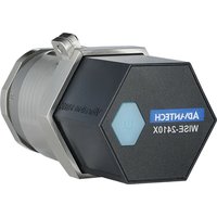
WISE-2410-EB - Monitoring sensor Advantech - Free user manual and instructions
Find the device manual for free WISE-2410-EB Advantech in PDF.


| Product Type | LoRaWAN Smart Condition Monitoring Sensor |
| Brand | Advantech |
| Model | WISE-2410-EB |
| Dimensions (Height x Diameter) | 84.7 mm x 48.3 mm |
| Weight | Approximately 200 g (with batteries) |
| Power Source | 2 x AA 3.6 V DC batteries (non-rechargeable) or Micro-B USB (5 V DC) |
| Battery Life | Depends on configuration; up to several months with periodic reporting |
| Enclosure Rating | IP66 |
| Wireless Interface | LoRaWAN (US 902-928 MHz, EU 863-870 MHz, JP 920-928 MHz, TW 920-925 MHz) |
| Transmit Power | Up to +20 dBm |
| Receiver Sensitivity | -136 dBm at 125 kHz bandwidth |
| Built-in Sensors | 3-axis accelerometer (vibration) and temperature sensor |
| Vibration Measurement | Velocity RMS, Acceleration (RMS & peak), Kurtosis, Crest factor, Skewness, Standard deviation, Displacement; Frequency range 10-1000 Hz; Amplitude ±16 g |
| Temperature Measurement | Range -20°C to +120°C, resolution 12-bit, accuracy ±2°C at 85°C |
| Mounting Options | Stud mount (1/4-28 UNF), magnetic base, adhesive pad |
| Configuration Interface | Micro-B USB (COM port) with CP210x driver; WISE Studio software |
| Operating Temperature | -20°C to +50°C (battery powered); -20°C to +85°C (USB powered) |
| Storage Temperature | -30°C to +85°C (without battery) |
| Humidity | 10% to 95% RH non-condensing (operating and storage) |
| Safety and Compliance | FCC Part 15 Class B, CE, NCC; Contains FCC ID: M82-WISE2410 |
| Warranty | 2 years from date of purchase |
| Maintenance | Replace batteries as needed; clean with dry cloth; avoid liquid ingress |
| Spare Parts / Accessories | AA 3.6V batteries (model 1760002647-01), mounting stud, magnetic base, adhesive pad |
Frequently Asked Questions - WISE-2410-EB Advantech
User questions about WISE-2410-EB Advantech
0 question about this device. Answer the ones you know or ask your own.
Ask a new question about this device
Download the instructions for your Monitoring sensor in PDF format for free! Find your manual WISE-2410-EB - Advantech and take your electronic device back in hand. On this page are published all the documents necessary for the use of your device. WISE-2410-EB by Advantech.
USER MANUAL WISE-2410-EB Advantech
The documentation and the software included with this product are copyrighted 2020 by Advantech Co., Ltd. All rights are reserved. Advantech Co., Ltd. also reserves the right to improve the products described in this manual at any time without notice. No part of this manual may be reproduced, copied, translated, or transmitted in any form or by any means without the prior written permission of Advantech Co., Ltd. The information provided in this manual is intended to be accurate and reliable. However, Advantech Co., Ltd. assumes no responsibility for its use, nor for any infringements of the rights of third parties that may result from its use.
Acknowledgments
Intel and Pentium are trademarks of Intel Corporation.
Microsoft Windows and MS-DOS are registered trademarks of Microsoft Corp.
All other product names or trademarks are properties of their respective owners.
Product Warranty (2 years)
Advantech warrants the original purchaser that each of its products will be free from defects in materials and workmanship for two years from the date of purchase.
This warranty does not apply to any products that have been repaired or altered by persons other than repair personnel authorized by Advantech, or products that have been subject to misuse, abuse, accident, or improper installation. Advantech assumes no liability under the terms of this warranty as a consequence of such events.
Because of Advantech's high quality-control standards and rigorous testing, most customers never need to use our repair service. If an Advantech product is defective, it will be repaired or replaced free of charge during the warranty period. For out-of-warranty repairs, customers are billed according to the cost of replacement materials, service time, and freight. Please consult your dealer for more details.
If you believe your product is defective, follow the steps outlined below:
-
Collect all the information about the problem encountered. (For example, CPU speed, Advantech products used, other hardware and software used, etc.) Note anything abnormal and list any onscreen messages displayed when the problem occurs.
-
Call your dealer and describe the problem. Please have your manual, product, and any helpful information readily available.
-
If your product is diagnosed as defective, obtain a return merchandise authorization (RMA) number from your dealer. This allows us to process your return more quickly.
-
Carefully pack the defective product, a completed Repair and Replacement Order Card, and proof of the purchase date (such as a photocopy of your sales receipt) into a shippable container. Products returned without a proof of purchase date are not eligible for warranty service.
-
Write the RMA number clearly on the outside of the package and ship the package prepaid to your dealer.
Part No. 2003240000 Edition 1
Printed in Taiwan October 2020
Declaration of Conformity
Notice to OEM integrator
-
In the users manual of the end of product, the end user has to be informed to keep at least 20cm separation with the antenna while this end product is installed and operated.
-
The antenna(s) used for this transmitter must not be collocated or operating in conjunction with any other antenna or transmitter within a host device, except in accordance with FCC multi-transmitter product procedures.
-
Only those antennas with same type and lesser gain filed under this FCC ID number can be used with this device.
-
The regulatory label on the final system must include the statement: "Contains FCC ID: M82-WISE2410" or using electronic labeling method as documented in KDB 784748.
-
The final system integrator must ensure there is no instruction provided in the user manual or customer documentation indicating how to install or remove the transmitter module except such device has implemented two-ways authentication between module and the host system.
-
The final host manual shall include the following regulatory statement: This equipment has been tested and found to comply with the limits for a Class B digital device, pursuant to Part 15 of FCC Rules. These limits are designed to provide reasonable protection against harmful interference in a residential installation. This equipment generates, uses, and can radiate radio frequency energy. If not installed and used in accordance with the instructions, it may cause harmful interference to radio communications. However, there is no guarantee that interference will not occur in a particular installation. If this equipment does cause harmful interference to radio or television reception, which can be determined by tuning the equipment off and on, the user is encouraged to try and correct the interference by one or more of the following measures:
■ Reorient or relocate the receiving antenna.
■ Increase the distance between the equipment and the receiver.
■ Connect the equipment to outlet on a circuit different from that to which the receiver is connected.
■ Consult the dealer or an experienced radio/TV technician for help.
This device complies with Part 15 of the FCC Rules. Operation is subject to the following two conditions: (1) This device may not cause harmful interference, and (2) this device must accept any interference received, including interference that may cause undesired operation.
FCC Caution: Any changes or modifications not expressly approved by the party responsible for compliance could void the user's authority to operate this equipment.
This transmitter must not be co-located or operating in conjunction with any other antenna or transmitter.
Radiation Exposure Statement:
This equipment complies with FCC radiation exposure limits set forth for an uncontrolled environment. This equipment should be installed and operated with minimum distance 20cm between the radiator & your body.
Technical Support and Assistance
- Visit the Advantech website at www.advantech.com/support to obtain the latest product information.
- Contact your distributor, sales representative, or Advantech's customer service center for technical support if you need additional assistance. Please have the following information ready before calling:
– Product name and serial number
– Description of your peripheral attachments
– Description of your software (operating system, version, application software, etc.)
– A complete description of the problem
– The exact wording of any error messages
Warnings, Cautions, and Notes
Warning! Warnings indicate conditions that if not observed may cause personal injury!

Caution! Cautions are included to help prevent hardware damage or data losses.

For example, "Batteries are at risk of exploding if incorrectly installed. Do not attempt to recharge, force open, or heat the battery. Replace the battery only with the same or equivalent type as recommended by the manufacturer. Discard used batteries according to the manufacturer's instructions." or "To prevent damages on the sensor, tensile stresses must be avoided under all driving conditions.
Note! Notes provide additional optional information.

Document Feedback
To assist us with improving this manual, we welcome all comments and constructive criticism. Please send all feedback in writing to support@advantech.com.
Packing List
Before setting up the system, check that the items listed below are included and in good condition. If any item does not accord with the table, please contact your dealer immediately.
WISE-2410
1 x WISE-2410 module
■ 1 x Mounting stud (1/4-28 UNF x 9.4Lmm)
■ 1 x Quick start manual
* 2 pcs AA 3.6VDC batteries should be ordered respectively
* Built-in Antenna
Safety Instructions
- Read these safety instructions carefully.
- Retain this user manual for future reference.
- For pluggable equipment, the power outlet socket must be located near the equipment and easily accessible.
- Place the equipment on a reliable surface during installation. Dropping or letting the equipment fall may cause damage.
- Ensure that the voltage of the power source is correct before connecting the equipment to a power outlet.
- All cautions and warnings on the equipment should be noted.
- If the equipment is not used for a long time, disconnect it from the power source to avoid damage from transient overvoltage.
- Never pour liquid into an opening. This may cause fire or electrical shock.
- Never open the equipment. For safety reasons, the equipment should be opened only by qualified service personnel.
- If one of the following occurs, have the equipment checked by qualified service personnel:
■ The USB port is damaged.
- Liquid has penetrated the equipment.
■ The equipment has been exposed to moisture.
The equipment is malfunctioning, or does not operate according to the user manual.
■ The equipment has been dropped and damaged.
■ The equipment shows obvious signs of breakage.
-
Do not leave the equipment in an environment with a storage temperature of below -20 °C (-4 °F) or above 85 °C (185 °F) USB powered/50 °C (122 °F).
-
Battery powered as this may cause damage. The equipment should be kept in a controlled environment.
-
CAUTION: Batteries are at risk of exploding if incorrectly replaced. Replace only with the same or equivalent type as recommended by the manufacturer. Discard used batteries according to the manufacturer's instructions.
-
According to IEC 704-1:1982 standards, the sound pressure level at the operator's position does not exceed 70 dB (A).
DISCLAIMER: These instructions are provided in accordance with IEC 704-1. Advantech disclaims all responsibility for the accuracy of any statements contained herein.
Safety Precautions - Static Electricity
Follow these simple precautions to protect yourself from harm and the products from damage:
- Disconnect the power supply before making any configuration changes. The sudden rush of power after connecting a jumper or installing a card may damage sensitive electronic components.
NCC 警语
Chapter 1 Product Overview ......1
1.1 Series Family and Specifications 2
1.2 Features 2
1.3 System Architecture 2
Figure 1.1 System Architecture ...... 2
1.4 Mechanical Design and Dimensions 3
Figure 1.2 WISE-2410 Dimension 3
1.5 LED 3
Figure 1.3 LED.... 3
Chapter 2 Product Specification......5
2.1 Wireless Interface 6
2.2 General 6
2.3 Power 6
2.4 Software 7
2.5 Configuration Interface....7
2.6 Sensor Specifications....7
Chapter 3 Mechanical and Hardware Installation 9
3.1 Interface Introduction ...... 10
Figure 3.1 WISE-2410 Interface Introduction ...... 10
3.2 Tighten two chassis.... 10
Figure 3.2 Tighten two chassis 10
3.3 Mounting 11
3.3.1 Installation Direction.... 11
Figure 3.3 WISE-2410 Installation Direction on motor.... 11
Figure 3.4 WISE-2410 Detail Installation Direction on motor .... 11
3.3.2 Stud mount....12
Figure 3.5 Stud mount .... 12
Figure 3.6 Stud mount 12
3.3.3 Magnetic bases....12
Figure 3.7 Magnetic bases 12
3.3.4 Adhesive Mounting Pad 13
Figure 3.8 Adhesive Mounting Pad.... 13
3.4 Battery Replacement.... 14
Figure 3.9 Battery Replacement Step 1.... 14
Figure 3.10Battery Replacement Step 2.... 14
Figure 3.11Battery Replacement Step 3.... 15
Figure 3.12Battery Replacement Step 4.... 15
Figure 3.13Battery Replacement Step 5.... 16
Figure 3.14Battery Replacement Step 6.... 16
Chapter 4 System Configuration .....17
4.1 Sensor and Gateway Connections.... 18
4.1.1 Sensor (WISE-2410) configuration 18
4.1.2 LoRaWAN gateway (WISE-6610) configuration 20
4.1.3 Binding Process Between WISE-2410 and WISE-6610 ..... 23
4.2 WISE-2410 Configuration 28
4.2.1 Information Page 28
4.2.2 Configuration 29
4.2.3 IO Status.... 31
4.2.4 Data Logger 33
4.2.5 Diagnostician 35
4.2.6 Downlink Command.... 35
4.3 Get Raw Data from WISE-2410.... 36
4.3.1 Standard operation mode 36
4.3.2 Real-Time operation mode 38
Appendix A Modbus Address.... 39
Chapter 1
Product Overview
1.1 Series Family and Specifications
Function Model Description
| LoRaWAN SmartCondition Monitoring WISE-2410 Sensor | Built-in 3 axis vibration and temperature sensor;Built-in antenna, support LoRaWAN |
1.2 Features
WISE-2410
■ Built-in 3 axis vibration and temperature sensor
■ Provide 3 axis vibration features (Velocity RMS, acceleration peak, etc.)
■ Compliant with ISO 10816: WISE-2410 can directly provide vibration features. By simple setting, user can monitor machine motor for evaluation of vibration severity.
■ Built-in antenna, support LoRaWAN
■ Powered by battery or USB port
IP66 enclosure
1.3 System Architecture
WISE-2410 transmits sensor data to WISE-6610 (via LoRaWAN) or 3rd party LoRaWAN gateway (via LoRaWAN). WISE-6610 provides Ethernet connectivity, and supports Modbus TCP, RESTful Web API for integration.

flowchart
graph TD
    A["Cloud Service"] --> B["Database"]
    B --> C["SCADA"]
    D["Ethernet/4G"] --> E["WISE-PaaS/EdgeLink WISE-6610 LoRaWAN Gateway"]
    F["Ethernet/4G"] --> G["3rd party LoRaWAN Gateway"]
    H["LoRaWAN"] --> I["WISE-2410 Vibration Sensor"]
    J["LoRaWAN"] --> K["WISE-2410 Vibration Sensor"]
    L["RESTful Web API MQTT Modbus TCP/OPC UA"] --> B
Figure 1.1 System Architecture
1.4 Mechanical Design and Dimensions

Figure 1.2 WISE-2410 Dimension
1.5 LED

Figure 1.3 LED
| LED Color Indication Behavior | ||
| Status Green | ON | Turn on 2 sec when power on |
| Turn on 1 ms when RF transmission | ||
| OFF Idle | ||
Chapter 2
Product Specification
2.1 Wireless Interface
-
Operating Frequency:
US 902-928 (MHz)
EU 863-870 (MHz)
JP 920-928 (MHz)
TW 920-925 (MHz) (AS923) -
Data Rate:
50 kbps at FSK mode EU
21.9 kbps at SF7 mode US
5.47 kbps at SF7 mode JP
5.47 kbps at CCS mode TW
- Antenna Gain:
902\~928 MHz: 1 dBi
863\~870 MHz: 1 dBi
-
Transmit Power: Up to +20 dBm
-
Receiver Sensitivity: -136 dBm at 125 kHz bandwidth
-
Topology: Star
Note! The transmitting distance is subject to the environment of application site. Please perform site survey to determine the set up range of the wireless network.
2.2 General
Enclosure: PC
■ Mounting: Stud mount, mounting pad and adhesives, magnetic base
■ Dimensions (Height x Diameter): 84.7 x 48.3 mm
■ Operation temperature:
– Powered by batteries: -20 \~ 50 °C
- Powered by Micro-B USB cable: -20 \~ 85 °C
■ Storage temperature: -30 \~ 85 °C (without battery)
■ Operating humidity: 10 \~ 95% RH (non-condensing)
■ Storage humidity: 5 \~ 95% RH (non-condensing)
Note! Equipment will operate below 30% humidity. However, static electricity problems occur much more frequently at lower humidity levels. Make sure you take adequate precautions when you touch the equipment. Consider using ground straps, anti-static floor coverings, etc. If you use the equipment in low humidity environments.
2.3 Power
WISE-2410 is designed for two AA 3.6 V _DC batteries as an power source. Press the power switch on the top of chassis (see the Figure 1.3 led) and turn on WISE-2410.
Note! Battery needs to order separately

1760002647-01 3.6V/2500mAh AA Cylindrical Battery (nonrechargeable).
2.4 Software
Utility: WISE Studio
2.5 Configuration Interface
WISE-2410
■ Interface: COM port through Micro-B USB interface
Connector: Micro-B USB
USB chipset: Silicon Labs CP210x
Driver: CP210x USB to UART Bridge VCP Drivers (https://support.advantech.com/support/DownloadSRDetail_New.aspx?SR_ID=1-13U9QTV&Doc_Source=Download)
2.6 Sensor Specifications
Vibration Sensor
Axis: X-Y-Z
■ Frequency Range: 10 \~ 1000 Hz
■ Amplitude Range: ±16 g
■ Detection type: Velocity RMS, Acceleration (RMS & peak)
■ Advanced: Kurtosis, Crest factor, Skewness, Standard deviation, Displacement
■ Resolution: 10 bit
■ Sensitivity: 31.2 mg/LSB (TYP.)
■ Noise: ±150 mg (MAX. TA = 25 °C. 0 g)
Temperature Sensor
■ Measurement Range (TA = 25 °C): -20 °C \~ 120 °C
■ Resolution: 12 bit
■ Accuracy: -2 °C with 85 °C; -5 °C with 120 °C
Chapter 3
Mechanical and Hardware Installation
3.1 Interface Introduction
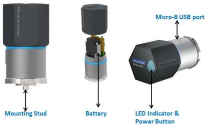
Figure 3.1 WISE-2410 Interface Introduction
3.2 Tighten two chassis
Turn clockwise the top chassis to locking point to tighten bottom chassis.

natural_image
Technical line drawing of a mechanical component with no visible text or symbolsFigure 3.2 Tighten two chassis
3.3 Mounting
Applicable installation methods are briefly described in the following sections.
3.3.1 Installation Direction
WISE-2410 Builds-in 3-axis vibration sensor. Please follow the following installation guide to make sure the eigenvalues from your device are correct.

Figure 3.3 WISE-2410 Installation Direction on motor
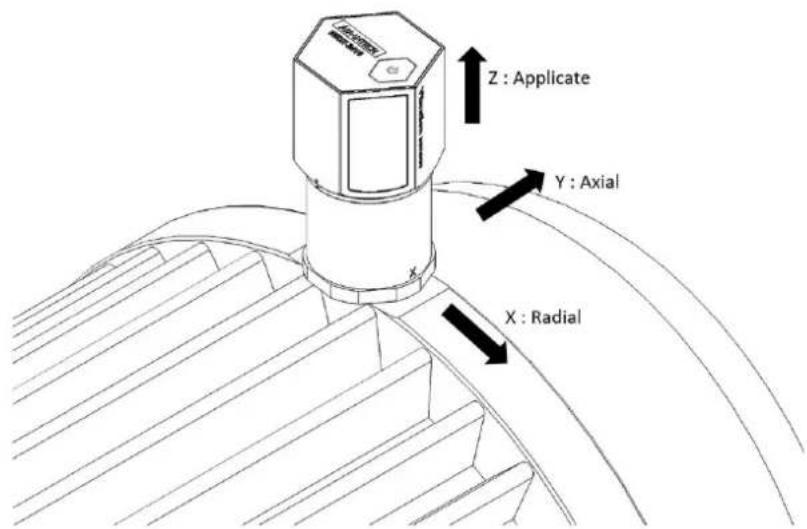
Figure 3.4 WISE-2410 Detail Installation Direction on motor
3.3.2 Stud mount
- Dig a hole in motor surface (1/4-28).
- Fasten WISE-2410 and stud (1/4-28 to 1/4-28).

natural_image
Technical line drawings of an electric motor and its internal components (no text or symbols)Figure 3.5 Stud mount
- Fasten WISE-2410 (with stud) and hold of motor surface.
Note! Please Wrench need to hold base steel (not contact chassis) when you use Wrench to fasten WISE-2410(with stud) to hold of motor.


natural_image
Close-up of a blue and silver adjustable wrench tool on a wooden surface, with a close-up view of its tip (no text or symbols visible)Figure 3.6 Stud mount
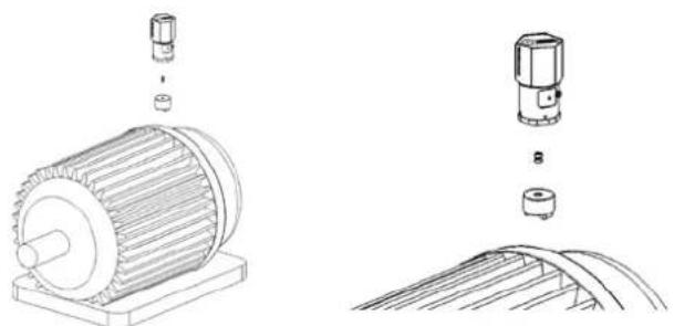
3.3.3 Magnetic bases
To avoid the sudden impact damage WISE-2410, please follow the following steps.
- First, fasten magnetic base on the motor.
- Fasten WISE-2410 and magnetic base.
natural_image
Technical line drawings of an electric motor and its internal components (no text or symbols)Figure 3.7 Magnetic bases
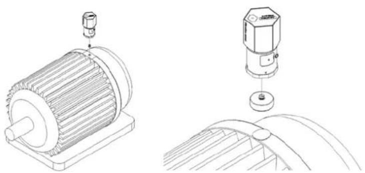
3.3.4 Adhesive Mounting Pad
Fasten WISE-2410 and stud, use adhesive epoxy glue(24hours) to stick on the motor surface.
natural_image
Technical line drawings of an electric motor and its internal components (no text or symbols)Figure 3.8 Adhesive Mounting Pad
3.4 Battery Replacement
- Slowly remove top chassis.

natural_image
Interior view of a battery pack with internal components and a green circuit board (no visible text or symbols)Figure 3.9 Battery Replacement Step 1
- Grab the Mylar and disconnect the connection between battery holder and PCBA.

natural_image
Close-up of a hand holding an open electronic circuit board with visible components and wiring (no readable text or symbols)Figure 3.10 Battery Replacement Step 2
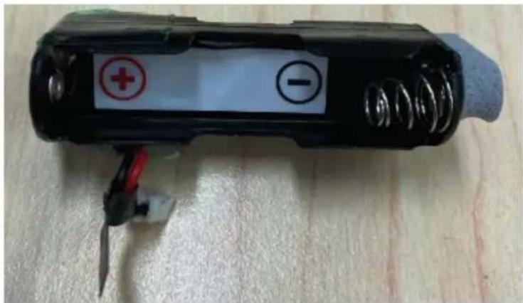
- Take out the battery holder and plug in new batteries. Please beard and make sure the batteries are both in the right anode and cathode position.
natural_image
Black cylindrical battery with two labeled terminals (red plus and black minus) placed on a textured surface, no visible text or symbols beyond the markings.Figure 3.11 Battery Replacement Step 3
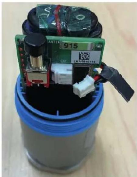
- Plug in the battery pack and make sure the cable is hidden between the PCBA and the battery pack as follow.
natural_image
Close-up of a green electronic circuit board with black components inside a blue cylindrical container (no visible text or symbols)Figure 3.12 Battery Replacement Step 4
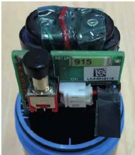
- Make the connection between battery holder and PCBA. Please make sure the cable has cross by the dent which is on the right side PCBA.
natural_image
Close-up of a green electronic device with black plastic components and a blue base, no visible text or symbols on the main subject.Figure 3.13 Battery Replacement Step 5

natural_image
Close-up of a blue cylindrical battery with attached electronic components and a green circuit board (no visible text or symbols)Figure 3.14 Battery Replacement Step 6
Chapter 4
System Configuration
4.1 Sensor and Gateway Connections
4.1.1 Sensor (WISE-2410) configuration
- Download and install WISE Studio through https://support.advantech.com/support/new_default.aspx.
- Connect the module to your computer via the micro-USB port.
-
Execute WISE Studio.
-
Clicking Go to Configuration while it shows "available USB-Serial" in USB-Serial box, press Go To Configuration.

- Click Connect to link the WISE-2410 and the web configuration page will appear.
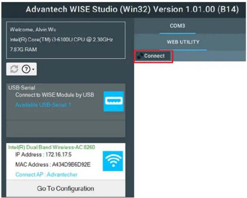
- Use web configuration in WISE Utility or press Open In Browser to open the web configuration in any browser (Google Chrome is recommended). Note: Web in WISE Utility is using IE browser.
PC Browser Chrome Firefox IE11 IE10
Data Log Export Y Y N N
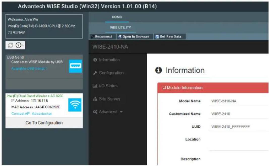
- Click Information to check the basic information of the module.
- Click Configuration to use Information, RF Module, Time&Date, Scheduling, Control, Firmware settings.
Configuration

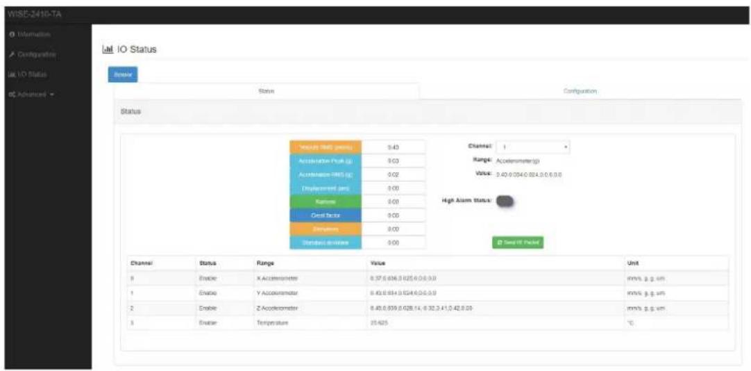
- Click IO Status to check vibration and temperature data.
4.1.2 LoRaWAN gateway (WISE-6610) configuration
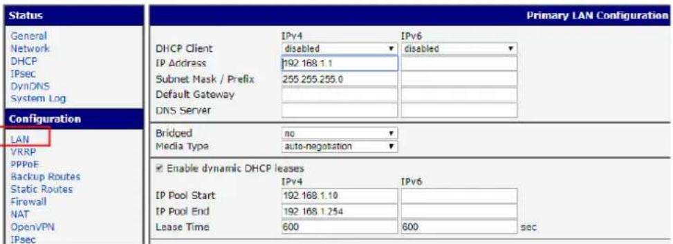
- Default IP of WISE-6610 is 192.168.1.1.
- Login-
Username: root
Password: root

You can see the main page of Router; you can change IP in LAN if needed.
SmartStart LAN Router
3. LoRaWAN setting.
Step1: Choose User Modules and LoRaWAN Gateway.
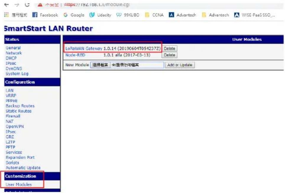
You can see WISE-6610N100-A (Support NA frequency band), make sure all of these parameters are matching with the RF module setting on WISE-2410.

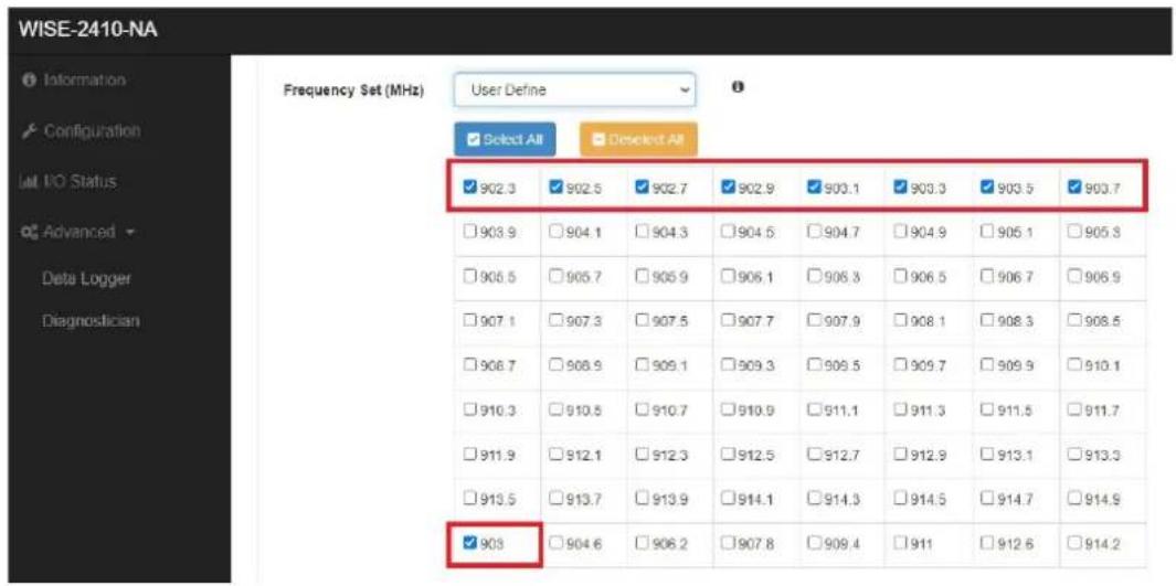
If you want to know any items' description, you can refer WISE-6610 user manual. A new tab will pop-up after click on Network Server (http).
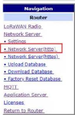
Account: root Password: root

4.1.3 Binding Process Between WISE-2410 and WISE-6610
This section will guide you to setup the connection between WISE-2410 and WISE-6610.
- Enter the "Network Server (http)" in WISE-6610 gateway as follow.

- Create an end node device according to the OTAA or ABP method. The following flow will use ABP mode for description the binding process.
Note: If select "Commissioned", which means the node will use OTAA mode for connecting with a gateway.
Note: If select "Active Nodes", which means the node will use ABP mode for connecting with a gateway.

- Click "Device" > "Activated (Nodes)" > "+ Create".

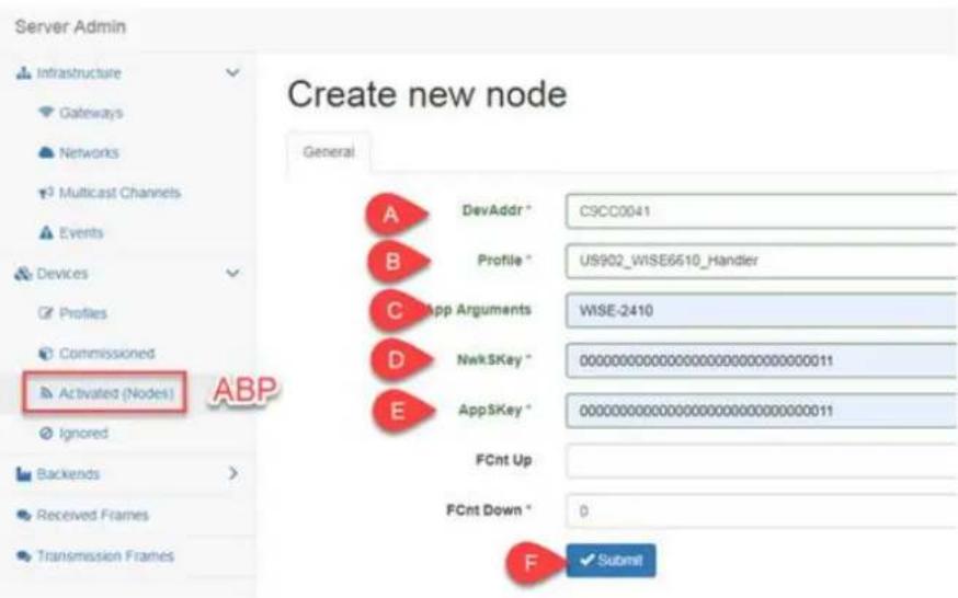
A. DevAddr: the device address of an end node.
Copy-pate "Device Address" from WISE-2410 "RF module" tab.
B. Profile: select the model name of the WISE-6610 which used for Network Server role.
In this demo, a US version is used to connect with WISE-2410NA version.
C. App Arguments: the I/O board of the end node.
In this demo, a WISE-2410 is used.
D. NwkSKey: the network service key address of an end node.
Copy-pate "Networks Session Key" from WISE-2410 "RF module" tab.
E. AppSKey: the application service key of an end node.
Copy-pate "Networks Session Key" from WISE-2410 "RF module" tab.
F. Click on "save" to finish the setting.

- Back to WISE-2410 configuration setting page. Click "Configuration" > "RF Module" and choose "LoRaWAN" for RF operation mode setting on WISE-2410.

- Create a "network server" gateway. Copy-paste the MAC address from "LoRaWAN radio" > "LoRaWAN Gateway Identifier". Then click on "submit".
![Server Admin Infrastructure Gateways Networks Multicast Channels Gateways List ④ ② + Create MAC Group Description IP Dwell [%] Last Alive Status](/content/2026/05/910370/images/68e4a62e6429c27b3103fc15a55bd153926577c0a9bc989494c5fe653352ca11.jpg)


- Connection Verify.
A. Click "Application Server" > "Status". Here shows the end nodes if packets are received by gateway from an end node.
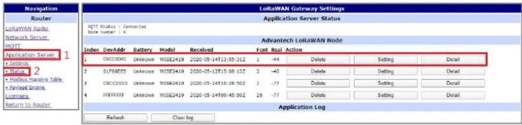
B. Click "Detail". The gateway will help to pre-parsing the data payload if the "App Arguments" input correctly.

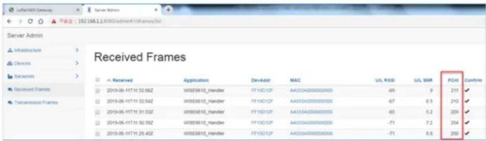
C. Users can also access into "Network Server (http)". The "Received frames" page shows the received results. The "FCnt" shows the frame sequence. If this sequence is in-continuously, means some of the packets were lost.
4.2 WISE-2410 Configuration
All functions of WISE Studio for WISE-2410 is below:
| System Function Item Functional Description | ||
| WISE Studio | Information | Display module name, Network status, Power status, Firmware version. |
| Configuration | ■ Module Information■ RF related setting■ Date/time, time zone settings■ Schedule of when sensor should start measurement■ System restart or reset to default■ Firmware download | |
| IO Status | ■ Display values which is measured by sensors.Include following types:- X Accelerometer- Y Accelerometer- Z Accelerometer- Temperature■ Sensor related settings | |
| Site Survey Site Survey Tool for testing the communication quality between WISE-2410 wireless module with gateway. | ||
| Data Logger | ■ Configurations of which channel, which type of sensor values to log data in module.■ Query log data stored in module. | |
| Diagnostician To display any errors detected by module. | ||
| Get Raw Data Query raw data which is measured by vibration sensor. | ||
4.2.1 Information Page
Information page is displayed Module Information, Power Status, LoRa Information, Device Information.

4.2.2 Configuration
It shows general configuration of WISE-2410 modules, including Information, RF module, Time&Date, Scheduling, Control and Firmware.
Information: Device identity and location settings
■ RF Module: RF Related Settings
Binding process between WISE-2410 and WISE-6610, please go to Section 4.1 for more details. For LoRaWAN parameter description, please check the document of "lorawan_regional_parameters" from LoRaWAN Alliance website.
- Message ACK: Advantech implement retry solution when WISE-2410 does not receive the acknowledgment from WISE-6610 or other 3rd party LoRaWAN gateway.
Application Information

■ Time & Date: time zone settings
- Local Time: WISE-2410 sync time with computer.
– Daylight Saving Time: Range setting for daylight saving time period.
■ Control: System restart or reset to default
Firmware
- Firmware Upload: To update the firmware, click "Firmware Upload" to update file. The latest official firmware releases are available on the Advantech support website (http://support.advantech.com/).
- Configuration File Upload: User can upload their specific "Configuration File".
- Configuration File Export: User can export their "Configuration File".
Configuration

■ Scheduling: Data reports interval setting with optional weekly scheduling setting Based on application scenario, user can set scheduling of WISE-2410.
- Mode: Basic/Advance
– Day: Mask for Sunday \~ Saturday - Start time: 00: 00 \~ 23: 59
- End time: 00: 00 \~ 23: 59
– Periodic interval: 10 \~ 86400 (sec)
Scenario A: Sensing target every minutes.

Scenario B: Sensing target on specific timing for better power saving application. In this example: Mon. 8:00am \~ Sun. 8:00 am.

Configuration

4.2.3 IO Status
Click IO Status to check vibration and temperature data.
- User can easily to see the detail data of all channels.
- User can choose channel 0, 1, 2 which means x, y, z axis to see the detailed vibration features (Velocity RMS, Acceleration Peak, and total eight features).

■ Vibration alarm (for Velocity RMS)
- Please select the channel for correspondent settings with each axis. 0 means X-axis. 1 means Y-axis. 2 means Z-axis.
- If the sensing target vibrate abnormally and pass through a threshold, it can send alarm to LoRa gateway.
IO Status

■ Temperature alarm
- Please select Channel 3 for Temperature sensor configuration.
– Sensor Offset Value: Offset setting between measurement temperature value and real temperature value.
- Enable: WISE-2410 will upload an alarm message according to the user-defined threshold value. If WISE-2410 detected a higher temperature value than the threshold setting, WISE-2410 will send a temperature alarm message to a gateway. This function is not limited by the data uplink period. In another word, If customer enables this function, WISE-2410 will keep monitoring the surface temperature every second.
- Send Alarm Event:
Continuously means WISE-2410 will keep sending an alarm message to a gateway until the WISE-2410 detected temperature is lower than the threshold value set by a user.
Four-time means WISE-2410 will send an alarm message to a gateway. If the WISE-2410 does not receive acknowledgment from the gateway, WISE-2410 will retry the alarm message with maximum 3 times.
IO Status

4.2.4 Data Logger
Configure or query logs stored in module.
1. Data Configuration
Log Conditions Default setting is to record the Velocity RMS alarm message if user has set a threshold on Velocity RMS values.
- By Period: Enable means the log function will run by period which includes the Velocity RMS alarm message.
General
- Clear Log when Power Up: Enable or Disable to reset the Built-in log when the system powers on.
- Circular Log when Memory Full: Enable or Disable the Circular Operation for Built-in Memory.
Log Data: User can choose the log by channel or by sensor
- By Channel: 0 means X-axis. 1 means Y-axis, 2 means Z-axis, 3 means Temperature.
- By Sensor: Data from sensors, including vibration features, alarm trigger, sensor status and raw data.

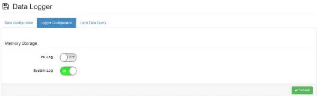
Logger Configuration: Enable or Disable the I/O log function. Default setting on I/O Log is disable, on System Log is enable.
Local Data Query
■ Push Data Query Format
- UUID: Enable or Disable the UUID.
- MAC ID: Enable or Disable the MAC ID.
- Timestamp: Local date and time (GMT) or Coordinated universal time (UTC).
■ Query Filter
- Filter Mode: User can choose No Filter Enable, Time Filter or Amount of Lat-est Data.
Data Logger

- Query result as follow:
Chart

bar
Io-Type Statistic | IO Type | Sensor Engineering Value | Sensor Status | Velocity RMS value | Acceleration Peak va... | Acceleration RMS val... | |---|---|---|---|---|---| | IO-Type_40 | 2.00 | | | | | | IO-Type_43 | | 2.00 | | | | | IO-Type_45 | | | 6.00 | | | | IO-Type_46 | | | | 6.00 | | | IO-Type_47 | | | | | 6.00 |
4.2.5 Diagnostician
Display any errors detected by module.

4.2.6 Downlink Command
For better user experience, WISE-2410 supports to config time and update interval remotely. Please contact local FAE for more detail technical supports.
4.3 Get Raw Data from WISE-2410
For WISE-2410 series, there are two operation modes for querying vibration raw data: Standard mode and Real Time mode.
Standard mode: User could query/get raw data which was previously measured and stored in WISE-2410.
Real Time mode: User could query/get raw data which was measured by WISE-2410 in real time.
Press "Get Raw Data" button in WISE Studio.

4.3.1 Standard operation mode
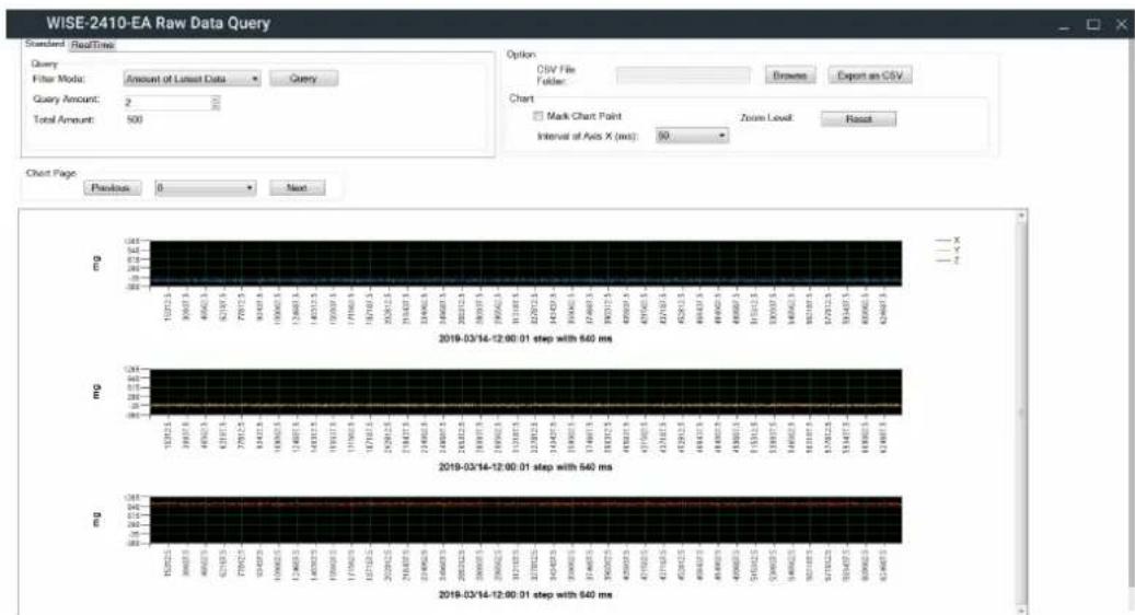
- In Standard operation mode, user could use "Amount of Latest data" or "Time Filter" as query criteria to get raw data.

- Press "Query button" and 3 charts (X, Y, Z axis) will display.
bar
WISE-2410-EA Raw Data Query | Query | Total Amount | |---|---| | mg | 500 | | mg | 500 | | mg | 500 | | mg | 500 | | mg | 500 | | mg | 500 | | mg | 500 | | mg | 500 | | mg | 500 | | mg | 500 | | mg | 500 | | mg | 500 | | mg | 500 | | mg | -19783.3 | | mg | -19813.3 | | mg | -19833.3 | | mg | -19853.3 | | mg | -19873.3 | | mg | -19893.3 | | mg | -19913.3 | | mg | -19933.3 | | mg | -19953.3 | | mg | -19973.3 | | mg | -19993.3 | | mg | -20013.3 | | mg | -20033.3 | | mg | -20053.3 | | mg | -20073.3 | | mg | -20093.3 | | mg | -20113.3 | | mg | -20133.3 | | mg | -20153.3 | | mg | -20173.3 | | mg | -20193.3 | | mg | -20213.3 | | mg | -20233.3 | | mg | -20253.3 | | mg | -20273.3 | | mg | -20293.3 | | mg | -20313.3 | | mg | -20333.3 | | mg | -20353.3 | | mg | -20373.3 | | mg | -20393.3 | | mg | -20413.3 | | mg | -20433.3 | | mg | -20453.3 | | mg | -20473.3 | | mg | -20493.3 | | mg | -20513.3 | | mg | -20533.3 | | mg | -20553.3 | | mg | -20573.3 | | mg | -20593.3 | | mg | -20613.3 | | mg | -20633.3 | | mg | -20653.3 | | mg | -20673.3 | | mg | -20693.3 | | mg | -20713.3 | | mg | -20733.3 | | mg | -20753.3 | | mg | -20773.3 | | mg | -20793.3 | | mg | -20813.3 | | mg | -20833.3 | | mg | -20853.3 | | mg | -20873.3 | | mg | -20893.3 | | mg | -20913.3 | | mg | -20933.3 | | mg | -20953.3 | | mg | -20973.3 | | mg | -20993.3 | | mg | -21013.3 | | mg | -21033.3 | | mg | -21053.3 | | mg | -21073.3 | | mg | -21093.3 | | mg | -21113.3 | | mg | -21133.3 | | mg | -21153.3 | | mg | -21173.3 | | mg | -21193.3 | | mg | -21213.3 | | mg | -21233.3 | | mg | -21253.3 | | mg | -21273.3 | | mg | -21293.3 | | mg | -21313.3 | | mg | -21333.3 | | mg | -21353.3 | | mg | -21373.3 | | mg | -21393.3 | | mg | -21413.3 | | mg | -21433.3 | | mg | -21453.3 | | mg | -21473.3 | | mg | -21493.3 | | mg | -21513.3 | | mg | -21533.3 | | mg | -21553.3 | | mg | -21573.3 | | mg | -21593.3 | | mg | -21613.3 | | mg | -21633.3 | | mg | -21653.3 | | mg | -21673.3 | | mg | -21693.3 | | mg | -21713.3 | | mg | -21733.3 | | mg | -21753.3 | | mg | -21773.3 | | mg | -21793.3 | | mg | -21813.3 | | mg | -21833.3 | | mg | -21853.3 | | mg | -21873.3 | | mg | -21893.3 | | mg | -21913.4 | | mg | -21934.4 | | mg | -21954.4 | | mg | -21974.4 | | mg | -21994.4 | | mg | 640ms (approx) from 640ms (approx) from 640ms (approx) from 640ms (approx) from 640ms (approx) from 640ms (approx) from 640ms (approx) from 640ms (approx) from 640ms (approx) from 640ms (approx) from 640ms (approx) from 640ms (approx) from ~64ms (approx) from 64ms (approx) from 64ms (approx) from 64ms (approx) from 64ms (approx) from 64ms (approx) from 64ms (approx) from ~64ms (approx) from 64ms (approx) from ~64ms (approx) from ~64ms (approx) from ~64ms (approx) from ~64ms (approx) from ~64ms (approx) from ~64ms (approx) from ~64ms (approx) from ~64ms (approx) from ~64ms (approx) from ~64ms (approx) from ~64ms (approx) from ~64ms (approx) from ~64ms(approx) from ~64ms (approx) from ~64ms (approx) from ~64ms (approx) from ~64ms (approx) from ~64ms (approx) from ~64ms (approx) from ~64ms (approx) from ~64ms (approx) from ~64ms (approx) from ~64ms (approx) from ~64ms (approx) from ~64ms (approx) from 64ms (approx) from ~64ms (approx) from ~64ms (approx) from ~64ms (approx) from ~64ms (approx) from ~64ms (approx) from ~64ms (approx) from ~64ms (approx) from ~64ms (approx) from ~64ms (approx) from ~64ms(approx) from ~64ms (approx) from ~64ms(approx) from ~64ms(approx) from ~64ms(approx) from ~64ms(approx) from ~64ms(approx) from ~64ms(approx) from ~64ms(approx) from ~64ms(approx) from ~64ms(approx) from ~64ms(approx) from ~64ms(approx) from ~64ms(approx) from ~64ms(approx) from 64ms(approx), from ~64ms(approx), from ~64ms(approx), from ~64ms(approx), from ~64ms(approx), from ~64ms(approx), from ~64ms(approx), from ~64ms(approx), from ~64ms(approx), from ~64ms(approx), from ~64ms(approx), from ~64ms(approx), from ~64ms(approx), from ~64ms, approx., Approx., Approx., Approx., Approx., Approx., Approx., Approx., Approx., Approx., Approx., Approx., Approx., Approx., Approx., Approx., Approx., Approx., Approx., Approx., Approx., Approx., Approx., Approx., Approx., Approx., Approx., Approx., Approx., Approx., Approx., Approx., Approx., Approx., Approx., Approx., Approx., Approx., Approx., Approx., Approx., Approx., Approx., Approx., Approx., Approx., Approx., Approx., Approx., Approx., Approx., mm mg mg mg mg mg mg mg mg mg mg mg mg mg mg mg mg mg mg mg mg mg mg mg mg mg mg mg mg mg mg mg mg mg mg mg mg mg mg mg mg mg mg mg mg mg mg mg mg mg mg mpg mpg mpg mpg mpg mpg mpg mpg mpg mpg mpg mpg mpg mpg mpg mpg mpg mpg mpg mpg mpg mpg mpg mpg mpg mpg mpg mpg mpg mpg mpg mpg mpg mpgIf there are more than one record, use could press "Previous" or "Next" to display selected record.

- Recordt data could be exported as CSV file. Please select file folder and press "Export as CSV" to export records.

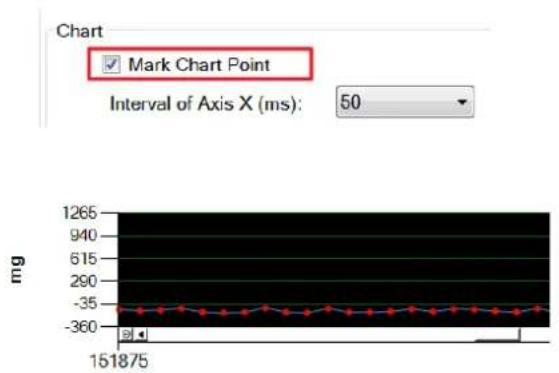
Mark data: User could click "Mark Chart Point" to show real data as a "Red Dot" in the chart.
line
| Time (ms) | Current (mg) | | --------- | ------------ | | 0 | -35 | | 151875 | -360 |4.3.2 Real-Time operation mode
- In Real-Time operation mode, user could get real time raw data. Please check "Export as CSV" to export records before pressing "Start" button.

- Press "Start" button and there will be 3 charts (X, Y, Z axis) displayed in real time.

line
| Channel | Amplitude (mg) | | ------- | -------------- | | A | 811 | | B | 510.6 | | C | 293.2 | | A | -354.5 | | B | -640 | | C | -708 | | A | 2241 | | B | 1251.3 | | C | 261.4 | | A | -1718.2 | | B | -2708 | | C | 2788 |- Press "Stop" button to terminate data query.
Appendix A
Modbus Address
WISE-2410 (for WISE-6610 LoRaWAN GW)
| Sensor Temperature 1 |
| Sensor Accelerometer Axis 3 |
Address 0X Ch Description Attribute
| 00231 0 (X) | AccelerometerHigh Alarm Flag | Read | ||
| 00232 1 (Y) Read | ||||
| 00233 2 (Z) Read | ||||
| 00234 | 3 (Temp) | Temperature High AlarmFlag | Read | |
Address 4X Ch Description Attribute
| 40501 | 0 (X) | OA Value of Vibration Velocity (0.01 mm/sec) | Read |
| 40502 | 1 (Y) | Read | |
| 40503 | 2 (Z) | Read | |
| 40504 | 3 (Temp) | Temperature Value (°C) | Read |
| 40701 | 0 (X) | Peak Value ofAcceleration (0.001g or 0.01m/s^2) | Read |
| 40702 | 1 (Y) | Read | |
| 40703 | 2 (Z) | Read | |
| 40721 | 0 (X) | RMS ofAcceleration(0.001g or 0.01m/s^2) | Read |
| 40722 | 1 (Y) | Read | |
| 40723 | 2 (Z) | Read | |
| 40741 | 0 (X) | Kurtosis (0.01) | Read |
| 40742 | 1 (Y) | Read | |
| 40743 | 2 (Z) | Read | |
| 40761 | 0 (X) | Crest factor (0.01) | Read |
| 40762 | 1 (Y) | Read | |
| 40763 | 2 (Z) | Read | |
| 40781 | 0 (X) | Skewness(0.01) | Read |
| 40782 | 1 (Y) | Read | |
| 40783 | 2 (Z) | Read | |
| 40801 | 0 (X) | Read | |
| 40802 | 1 (Y) Read | Standard deviation (0.01) | |
| 40803 | 2 (Z) Read | ||
| 40821 | 0 (X) | Read | |
| 40822 | 1 (Y) Read | Peak-to-Peak Displacement (μm) | |
| 40823 | 2 (Z) Read | ||
www.advantech.com
Please verify specifications before quoting. This guide is intended for reference purposes only.
All product specifications are subject to change without notice.
No part of this publication may be reproduced in any form or by any means, such as electronically, by photocopying, recording, or otherwise, without prior written permission of the publisher.
All brand and product names are trademarks or registered trademarks of their respective companies.
© Advantech Co., Ltd. 2020

- Acknowledgments
- Product Warranty (2 years)
- Declaration of Conformity
- Notice to OEM integrator
- Technical Support and Assistance
- Warnings, Cautions, and Notes
- Document Feedback
- Packing List
- WISE-2410
- Safety Instructions
- Safety Precautions - Static Electricity
- NCC 警语
- Chapter 1 Product Overview ......1
- Chapter 2 Product Specification......5
- Chapter 3 Mechanical and Hardware Installation 9
- Chapter 4 System Configuration .....17
- Appendix A Modbus Address.... 39
- Chapter 1
- Series Family and Specifications
- Features
- System Architecture
- Mechanical Design and Dimensions
- LED
- Chapter 2
- Wireless Interface
- General
- Power
- Software
- Configuration Interface
- Sensor Specifications
- Vibration Sensor
- Temperature Sensor
- Chapter 3
- Interface Introduction
- Tighten two chassis
- Mounting
- Installation Direction
- Stud mount
- Magnetic bases
- Adhesive Mounting Pad
- Battery Replacement
- Chapter 4
- Sensor and Gateway Connections
- Sensor (WISE-2410) configuration
- LoRaWAN gateway (WISE-6610) configuration
- SmartStart LAN Router
- LoRaWAN setting.
- Binding Process Between WISE-2410 and WISE-6610
- WISE-2410 Configuration
- Information Page
- Configuration
- Configuration
- IO Status
- ■ Temperature alarm
- Data Logger
- Data Configuration
- Local Data Query
- Diagnostician
- Downlink Command
- Get Raw Data from WISE-2410
- Standard operation mode
- Real-Time operation mode
- Appendix A
- www.advantech.com
Brand : Advantech
Model : WISE-2410-EB
Category : Monitoring sensor