
DFL-M510 - Uncategorized D-LINK - Free user manual and instructions
Find the device manual for free DFL-M510 D-LINK in PDF.


| Product Type | Information Security Gateway (ISG) |
| Brand | D-Link |
| Model | DFL-M510 |
| Dimensions (L x D x H) | 440 mm x 250 mm x 44 mm |
| Weight | Approximately 3 kg |
| Power Supply | AC 100-240V, 50-60Hz, 0.8A MAX |
| CPU | D-Link SOC DL-5100 |
| System Memory | 128 MB SDRAM, 16 MB Flash |
| Ethernet Ports | 2 x 10/100 Mbps auto-sensing with auto-crossing |
| Console Port | RS-232 (9-pin) |
| LCD Module | Blue background with white light LCD panel |
| Operating Modes | In-Line, Bypass, Monitor, SPAN |
| Concurrent Users | 150 |
| Concurrent TCP Sessions | 4,000 |
| Performance | 30-40 Mbps (all functions enabled) |
| Application Detection | IM, P2P, Web, File Transfer, Streaming Media, Mail, etc. |
| Management Interfaces | Web GUI (HTTP), SSH, CLI (Console), SNMP v2 |
| Security Certifications | CE, C-Tick, TUV, UL, FCC Class A |
| Operating Temperature | 0°C to 60°C |
| Storage Temperature | -20°C to 70°C |
| Humidity (Operating) | 10% to 90% RH (non-condensing) |
| Maintenance | Clean with a dry cloth; no liquid cleaners |
| Spare Parts / Repairability | Not specified; contact D-Link support |
Frequently Asked Questions - DFL-M510 D-LINK
User questions about DFL-M510 D-LINK
0 question about this device. Answer the ones you know or ask your own.
Ask a new question about this device
Download the instructions for your Uncategorized in PDF format for free! Find your manual DFL-M510 - D-LINK and take your electronic device back in hand. On this page are published all the documents necessary for the use of your device. DFL-M510 by D-LINK.
USER MANUAL DFL-M510 D-LINK
Building Networks for People
INFORMATION SECURITY GATEWAY(ISG)
USER MANUAL
DFL-M510
NETWORK SECURITY SOLUTION http://www.dlink.com
Before you Begin
Before you begin using this manaul, take a look at the copyright, trademark, and safety information in this section.
Copyright
This publication, including all photographs, illustrations and software, is protected under international copyright laws, with all rights reserved. Neither this manual, nor any of the material contained herein, may be reproduced without written consent of D-Link.
Copyright 2005
Version 1.0
Disclaimer
The information in this document is subject to change without notice. The manufacturer makes no representations or warranties with respect to the contents hereof and specifically disclaims any implied warranties of merchantability or fitness for any particular purpose. The manufacturer reserves the right to revise this publication and to make changes from time to time in the content hereof without obligation of the manufacturer to notify any person of such revision or changes.
Trademark Recognition
MSN () is a registered trademark of Microsoft Corporation
ICQ () is a registered trademark of ICQ Inc.
Yahoo () is a registered trademark of Yahoo! Inc.
QQ () is a registered trademark of TENCENT Inc.
Skype () is a registered trademark of Skype Technologies.
IRC () is a registered trademark of mIRC Co. Ltd.
Odigo () is a registered trademark of Comverse Technology, Inc.
Rediff () is a registered trademark of rediff.com India Limited.
czPeer() is a registered trademark of
Kuro ()is a registered trademark of music.com.tw Int.
Gnutella () is a registered trademark of OSMB, LLC
Kazza () is a registered trademark of Sharman Networks
BitTorrent () is a registered trademark of BitTorrent, Inc.
DirectConnect () is a registered trademark of Neo Modus Inc.
PP365 () is a registered trademark of pp365.com Inc.
WinMX (✗) is a registered trademark of Frontcode Technologies
GetRight () is a registered trademark of Headlight Software. Inc.
MS Media Player ( ) is a registered trademark of Microsoft Corporation
iTunes ( ) is a registered trademark of Apple Computer, Inc.
Winamp () is a registered trademark of Nullsoft
Player365 () is a registered trademark of Nullsoft Live365, Inc.
D-Link is a registered trademark of D-Link Systems, Inc.
Java is a trademarks or registered trademark of Sun Microsystems, Inc. in the United States and other countries.
All other product names used in this manual are the properties of their respective owners and are acknowledged.
Federal Communications Commission (FCC)
This equipment has been tested and found to comply with the limits for a Class A digital device, pursuant to Part 15 of the FCC Rules. These limits are designed to provide reasonable protection against harmful interference in a residential installation. This equipment generates, uses, and can radiate radio frequency energy and, if not installed and used in accordance with the instructions, may cause harmful interference to radio communications. However, there is no guarantee that interference will not occur in a particular installation. If this equipment does cause harmful interference to radio or television reception, which can be determined by turning the equipment off and on, the user is encouraged to try to correct the interference by one or more of the following measures:
- Reorient or relocate the receiving antenna.
- Increase the separation between the equipment and the receiver.
- Connect the equipment onto an outlet on a circuit different from that to which the receiver is connected.
- Consult the dealer or an experienced radio/TV technician for help.
Shielded interconnect cables and a shielded AC power cable must be employed with this equipment to ensure compliance with the pertinent RF emission limits governing this device. Changes
or modifications not expressly approved by the system's manufacturer could void the user's authority to operate the equipment.
Declaration of Conformity
This device complies with part 15 of the FCC rules. Operation is subject to the following conditions:
• This device may not cause harmful interference, and
- This device must accept any interference received, including interference that may cause undesired operation.
Safety Certifications
CE, C-Tick, TUV, UL
About this Manual
This manual provides information for setting up and configuring the DFL-M510. This manual is intended for network administrators.
Safety Information
READ THIS IMPORTANT SAFETY INFORMATION SECTION. RETAIN THIS MANUAL FOR REFERENCE. READ THIS SECTION BEFORE SERVICING.
CAUTION:
To reduce the risk of electric shock, this device should only be serviced by qualified service personnel.
- Follow all warnings and cautions in this manual and on the unit case.
- Do not place the unit on an unstable surface, cart, or stand.
- Avoid using the system near water, in direct sunlight, or near a heating device.
- Do not place heavy objects such as books or bags on the unit.
- Only use the supplied power cord.
Table of Contents
Chapter 1:
Getting Started with the DFL-M510 1
Identifying Components 1
Front View....1
Rear View 3
Configuring the DFL-M510 3
Configuration Through the Command Line Interface 3
Configuration Through a Web-based Interface 7
Running the Setup Wizard 10
Chapter 2:
System 15
The System Screen 15
Running the Setup Wizard 15
The Date & Time Screen 21
The Network Screen 23
Network Setting Tab.... 23
Interface Tab 28
Remote Access Tab 29
Parameter Tab 32
VLAN Tab 36
The Maintenance Screen 39
Configuration Tab.... 40
Account Tab.... 43
Chapter 3:
Host/Groups 47
The Host/Groups Screen 47
The Setup Hosts Tab.... 47
Exporting a Host Database 50
The Setup Groups Tab.... 51
Chapter 4:
Policy 55
The Policy Screen 55
Running the Template Wizard 56
The Policy Setting Screen 58
The Template Setting Tab 63
The Assign Policy Tab.... 66
The Policy Viewer Tab.... 68
User Defined Pattern 68
Defining a Pattern by Protocol 69
Defining a Pattern by Server.... 71
The Schedule Screen 72
Message Setting 74
Keyword Filter 76
Chapter 5:
Real Time Monitor 79
The Real Time Monitor Screen 79
Monitoring Real Time Traffic 80
Monitoring Real Time Application 81
Common Network Protocol.... 82
Health Checking 82
EIM 83
Two Levels Top N Analysis 84
Chapter 6:
Report & Log 91
The Report & Log Screen 91
The Report Tab 92
The Log Tab 94
Chapter 7:
Status 97
The Status Screen 97
The Device Info. Tab 98
The Policy Status Tab.... 100
Appendix A:
The Command Line Interface 105
Terminal/SSH (Secure Shell) Connection 105
Getting Started 106
CLI Command List 106
Help Command 106
Get Command 107
Set Command 108
“set system” command.... 109
“set time” command 111
“set state” command.... 112
“set remote” command.... 113
“set interface” command.... 115
History Command 115
Exit Command 115
Reboot Command 116
Reset Command 116
Ping Command 116
Appendix B:
Glossary 117
Appendix C:
Features and Specifications 121
Hardware Specification 121
Features Specification 121
LCM Module 123
Other Specifications 124
Mechanic & ID Design Front LED indicators 127
Physical Environment 128
Index 129
CHAPTER 1:
GETTING STARTED WITH THE DFL-M510
The DFL-M510 is a transparent network device. To ensure there is no disruption to your network, it can be installed in In-Line mode with a hardware bypass function enabled. The hardware bypass ensures that if the DFL-M510 crashes, experiences a power out or some other problem, your network is still up and running. This allows your network administrator to begin monitoring selected PCs, while checking for anything that may upset your current network environment. Refer to the Quick Guide for instructions on connecting the DFL-M510 to your network. This section covers the following topics:
- "Identifying Components" on page 1
- "Configuring the DFL-M510" on page 3
- “Running the Setup Wizard” on page 10

Before using this manual, take a look at the copyright, trademark, and safety information section. See "Before you Begin" on page i.
Identifying Components
The following illustrations show the front and rear of the DFL-M510.
FRONT VIEW
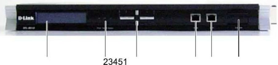
6
| 1 LCD | Console |
| 2 Status LEDs | |
| 3 LCM | Navigation Buttons |
| 4 WAN | Port |
| 5 LAN | Port |
| 6 Console Port | |
LCM BUTTON DESCRIPTION
The LCM buttons are described below.
| Button Name Description | ||
| Up Scroll Up | ||
| Down Scroll Down | ||
| ESC Go back to the previous screen | ||
| Enter Next screen |
STATUS LEDs
The following table describes the status LEDs on the front of the DFL-M510.
| Function Naming Color Status LED Description | ||||
| Power Power Green Off Power off | ||||
| On Power | ||||
| System | System | Green Off | Power off (System not ready) | |
| On System | ready and running ok | |||
| Bypass | Bypass | Red | Off | Hardware bypass is not enabled |
| On Hardware bypass is enabled | ||||
| Inbound (Left) | Inbound (LAN) | Green Off | Ethernet link OK and the speed is 10Mbps | |
| On Ethernet link OK and the speed is 100Mbps | ||||
| Inbound (Right) | Green Off | No packets sending/receiving | ||
| On Link | ||||
| Blinking | Activity, port is sending/receiving data | |||
| Outbound (Left) | Outbound (WAN) | Green Off | Ethernet link ok, and the speed is 10Mbps | |
| On Ethernet link ok, and the speed is 100Mbps | ||||
| Outbound (Right) | Green Off | No packets sending/receiving | ||
| On Link | ||||
| Blinking | Activity, port is sending/receiving data | |||
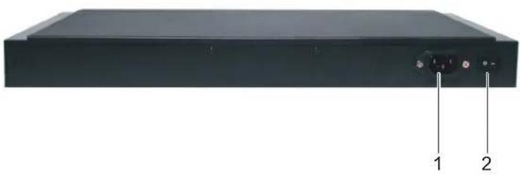
REAR VIEW
natural_image
Front view of a black electronic device with two labeled ports (1 and 2), no visible text or symbols on the body.| 1 Power socket |
| 2 Power switch |

Detailed information on the LCM can be found in the Appendix. See "Appendix A: The Command Line Interface" on page 105.
Configuring the DFL-M510
Before managing the DFL-M510, it must be initialized. This procedure is accomplished through the DFL-M510 Command Line Interface. Access to the Command Line Interface can be made either through SSH or from a terminal connected directly to the DFL-M510.
You can use Hyper Terminal, SSH v2 or browser to set up the IP parameters of the DFL-M510. The following are the default settings:
| IP Address 192.168.1.1 | |
| Subnet Mask 255.255.255.0 | |
| Default Gateway 192.168.1.254 | |
| User name admin | |
| Password admin | |
CONFIGURATION THROUGH THE COMMAND LINE INTERFACE
Configure the DFL-M510 using the following parameters.

The IP address shown below is only an example. Instead use the IP address for your network.
| IP Address 192.168.62.100 |
| Subnet Mask 255.255.255.0 |
| Default Gateway 192.168.62.1 |
- Connect one end of the RS-232 cable to the console port on the DFL-M510 and the other end to the COM1 or COM2 port on the PC. (The pin out definitions are shown below.)
| Terminal Emulation VT-100, ANSI, ot auto | |
| Bit per Second 115200 | |
| Data Bits 8 | |
| Parity None | |
| Stop Bits 1 | |
| Flow Control Nine |
-
To open a connection in Windows 95/98/NT/2000/XP go to, Program Files → Accessory → Communications → Super Terminal.
-
Once you access the Command Line Interface (CLI) with a terminal connection, press any key. The following prompt appears:
Welcome to D-Link DFL-M510 Console Environment
Copyright (C) 2005 D-Link Corp.
- Type in the username and password.
Welcome to D-Link DFL-M510 Console Environment
Copyright (C) 2005 D-Link Corp. <www.dlink.com>
DFL-M510 login: admin
Password:
>>> Welcome to the DFL-M510 Administration Console <<
You can configure and manage your DFL-M510 system
by making selections from the displayed menu.
help - This message.
get - Get system information.
set - Set system parameters.
history - Show all command history.
exit - Log out.
reboot - Reboot system.
reset - Reset system configurations to manufacturing defaults.
ping - Ping utility
>> _
- Use the get system command to get information on the DFL-M510.
Device name: DFL-M510
MAC Address: 00:0a:1b:12:12:88
DFL-M510 IP Address:192.168. 1. 1, netmask:255.255.255. 0,
gateway:192.168. 1.254
TCP cold start duration time: 30 seconds
VLAN function: off. VLAN ID: 0.
Detection parameters:
Maximum ping packet size: 1000.
TCP state check bypass: on.
WAN port: policy check < on> Stealth <off> max ping 10000.
LAN port: policy check < on> Stealth <off> max ping 10000.
Remote access:
HTTP:
Access: all
1 - Client IP: all    Netmask: 255.255.255. 0
2 - Client IP: 0. 0. 0. 0 Netmask: 255.255.255. 0
3 - Client IP: 0. 0. 0. 0 Netmask: 255.255.255. 0
SSH:
Access: all
1 - Client IP: all    Netmask: 255.255.255. 0
2 - Client IP: 0. 0. 0. 0 Netmask: 255.255.255. 0
3 - Client IP: 0. 0. 0. 0 Netmask: 255.255.255.  |
>>
- Use the set system ip command to set the IP address.
Password:
>>> Welcome to the DFL-M510 Administration Console <<
You can configure and manage your DFL-M510 system
by making selections from the displayed menu.

help - This message.
get - Get system information.
set - Set system parameters.
history - Show all command history.
exit - Log out.
reboot - Reboot system.
reset - Reset system configurations to manufacturing defaults.
ping - Ping utility

>> set system ip 192.168.62.100
Do you want to apply this setting immediately?
Your current ssh/http connection will be cut off. (y/n) y
Change device ip OK.

Device ip is changed, reboot now
Are you sure to reboot system? (y/n) y
- After the system reboots, use set system gateway to set the default gateway.
Password:
>>> Welcome to the DFL-M510 Administration Console <<
You can configure and manage your DFL-M510 system
by making selections from the displayed menu.

help - This message.
get - Get system information.
set - Set system parameters.
history - Show all command history.
exit - Log out.
reboot - Reboot system.
reset - Reset system configurations to manufacturing defaults.
ping - Ping utility

>> set system gateway 192.168.62.1
Do you want to apply this setting immediately?
Your current ssh/http connection will be cut off. (y/n) y
route: SIOC[ADD|DEL]RT: No such process
Change device gateway OK.

>> _
- After setting the IP address, Mask and Gateway, use the get system command to get correct information. Use the web-based interface to configure other parameters. See "Configuration
Through a Web-based Interface" on page 7.
Device name: DFL-M510
MAC Address: 00:0a:1b:12:12:88
DFL-M510 IP Address:192.168. 62.100, netmask:255.255.255. 0,
gateway:192.168. 62. 1
TCP cold start duration time: 30 seconds
VLAN function: off. VLAN ID: 0.
Detection parameters:
Maximum ping packet size: 1000.
TCP state check bypass: on.
WAN port: policy check < on> Stealth <off> max ping 10000.
LAN port: policy check < on> Stealth <off> max ping 10000.
Remote access:
HTTP:
Access: all
1 - Client IP: all    Netmask: 255.255.255. 0
2 - Client IP: 0. 0. 0. 0 Netmask: 255.255.255. 0
3 - Client IP: 0. 0. 0. 0 Netmask: 255.255.255. 0
SSH:
Access: all
1 - Client IP: all    Netmask: 255.255.255. 0
2 - Client IP: 0. 0. 0. 0 Netmask: 255.255.255. 0
3 - Client IP: 0. 0. 0. 0 Netmask: 255.255.255.  |
>>
CONFIGURATION THROUGH A WEB-BASED INTERFACE
The DFL-M510 GUI is a Web-based application that allows you to manage the DFL-M510. The GUI is a Java™ applet application. Before accessing the GUI from any PC, you must install Java Run Time Environment (J2RE V1.4.2 or above). Then you can log on to the DFL-M510 from any computer on the network via a Web browser. You can download J2RE from www.java.com or you can download it from the link within the DFL-M510 GUI.
The PC you log in from must have the following system requirements:
- Microsoft Windows XP professional operation systems
• Device with Internet connection
• CPU: Intel Pentium IV 2.0G or 100% compatible
• Memory: 512MB RAM or above
• Java Run Time Environment (J2RE V1.4.2 or above)
Refer to the following to log on to the DFL-M510.
- Open your Web browser and type the IP address into the Address Bar: http://192.168.1.1 The login screen appears.
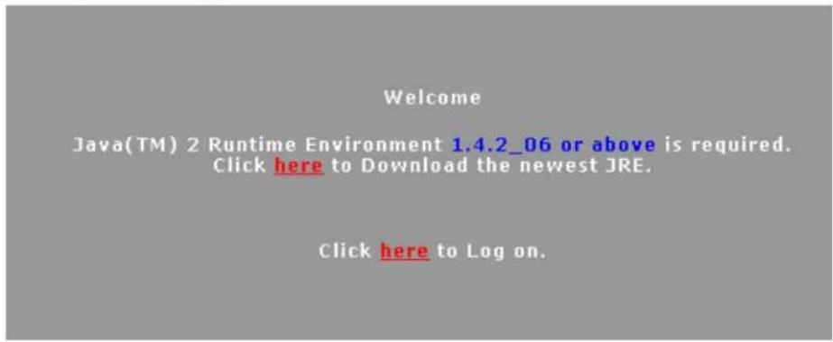
- Click on the link to download the Java Runtime Environment.
- Click Run to start the installation. Follow the onscreen prompts to complete the installation. The following Security Warning appears.
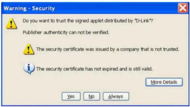
- Click Always to continue and prevent this screen appearing again. The login screen appears.

The IP address shown below is only an example. Instead use the IP address for your network.
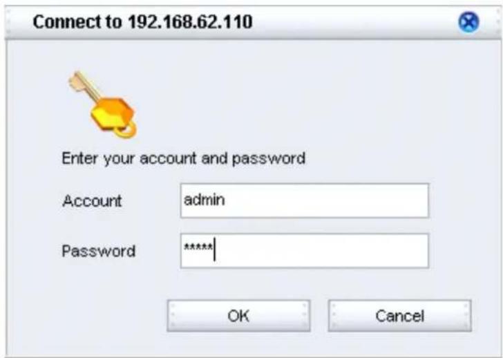
- Type in the default account name admin and the default password admin and click OK.

For security reasons, you should change the default password to a more secure password after you have completed the setup. See "Account Tab" on page 43.
- After two or three minutes the GUI opens on the DFL-M510 main screen.
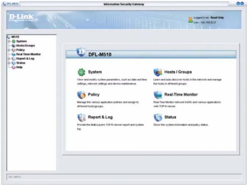
- To log out click the Close button at the top-right of the screen.
Running the Setup Wizard
The Setup Wizard helps you to quickly apply basic settings for the DFL-M510. You will need the following information for your network to complete the Setup Wizard:
• I P A d d r e s s
- Subnet Mask
- Default Gateway
- DNS Server
To run the Setup Wizard.

The first time you log on to the DFL-M510, the Setup Wizard starts automatically.
1. Click System, Setup Wizard.
The Setup Wizard window appears.
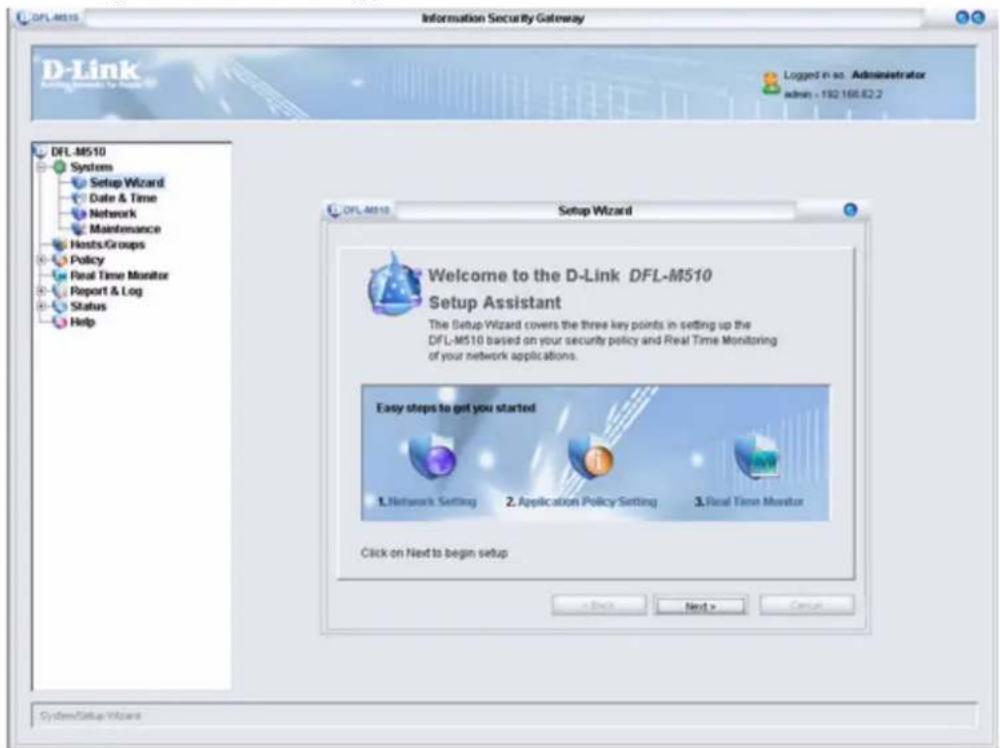
2. Click Next to continue.
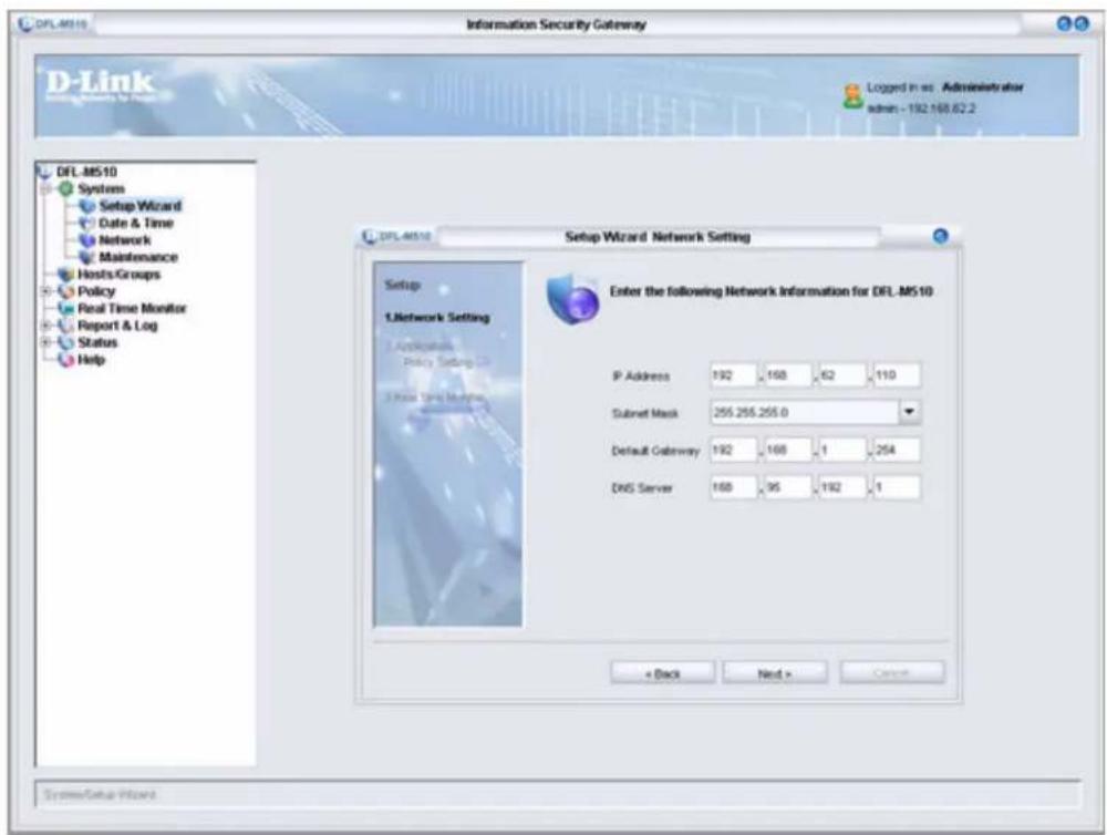
- You need to provide your IP Address, Subnet Mask, Default Gateway, and DNS Server address to enable the device to connect to your network. If the network was set by CLI, check the settings here.
Type in the required information and click Next.
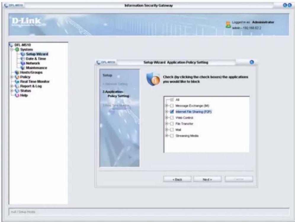
- Select the check boxes for the applications you want to block and click Next.

You can leave all the boxes unchecked to be sure the DFL-M510 is set up correctly. Later you can add applications to be blocked in the Policy menu. See "Chapter 4: Policy" on page 55.
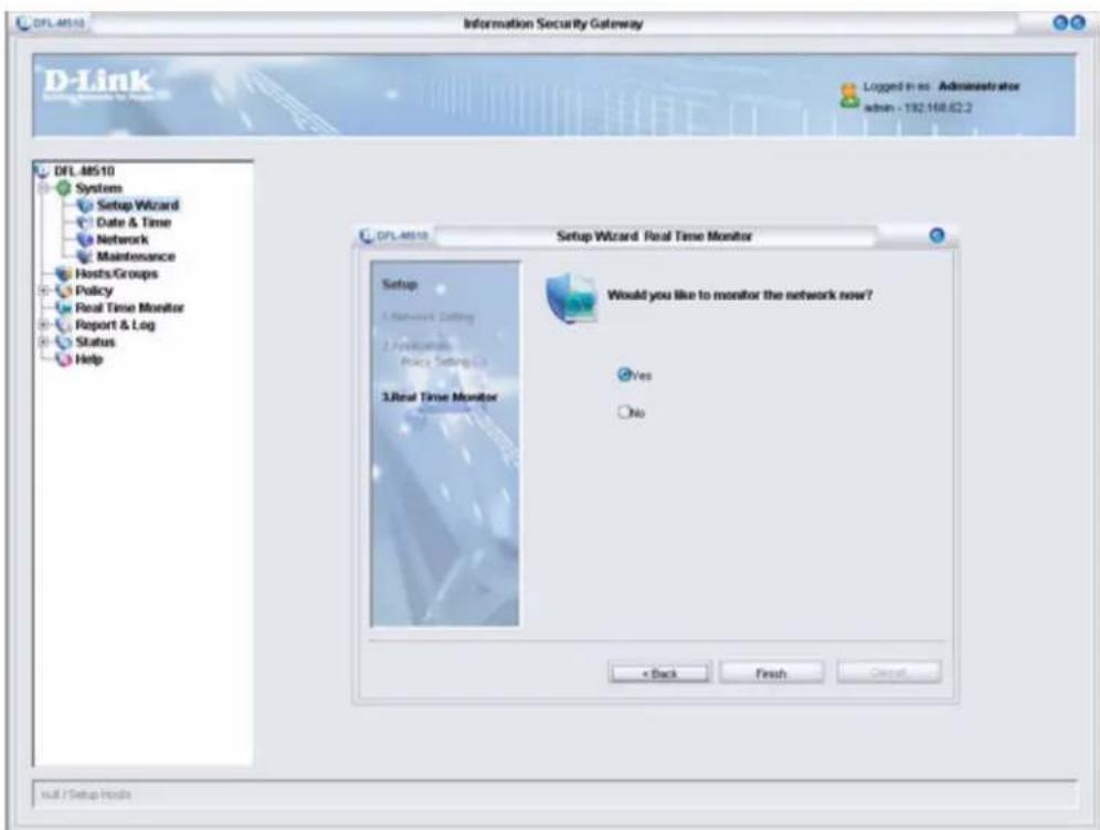
- Select the No radio button and click Finish.

If you select Yes in the screen above, you are taken to the Real Time Monitor screen when setup completes. See "Chapter 5: Real Time Monitor" on page 79.
It takes 30 seconds for the settings to be processed and then the following screen appears:
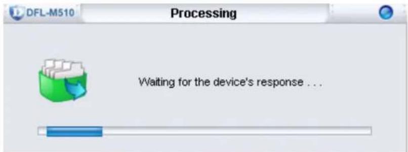
When the setup is successful, the following screen appears:
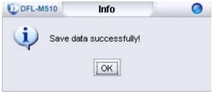
- Click OK. You are returned to the System menu.
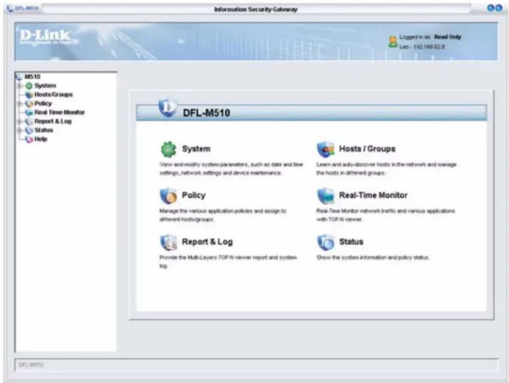
CHAPTER 2: SYSTEM
The System menu is where you carry out the basic setup of the DFL-M510 such as integration with your network. The System menu also lets you set local time settings and carry out maintenance.
The System Screen
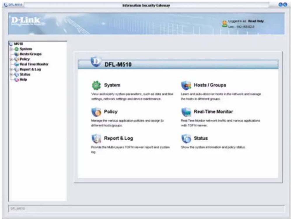
After you log on, click System to open the following screen:
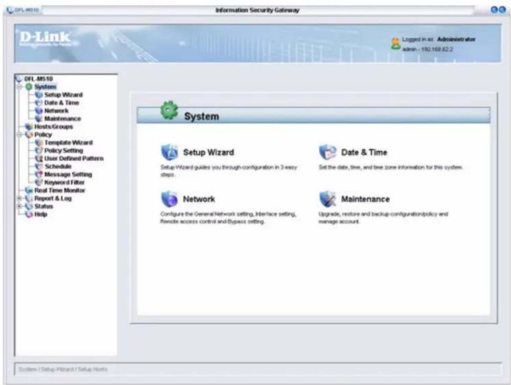
The System screen gives you access to the following screens:
- "Running the Setup Wizard" on page 15
• “The Date & Time Screen” on page 21
• "The Network Screen" on page 23
• “The Maintenance Screen” on page 39
Running the Setup Wizard
The Setup Wizard helps you to quickly apply basic settings for the DFL-M510. You will need the following information for your network to complete the Setup Wizard:
• I P A d d r e s s
- Subnet Mask
- Default Gateway
- DNS Server
 | The first time you log on to the DFL-M510, the Setup Wizard runs automatically. You can run the Setup Wizard anytime you want to change the basic configuration. |
To run the Setup Wizard.
1. Click System, Setup Wizard.
The Setup Wizard window appears.
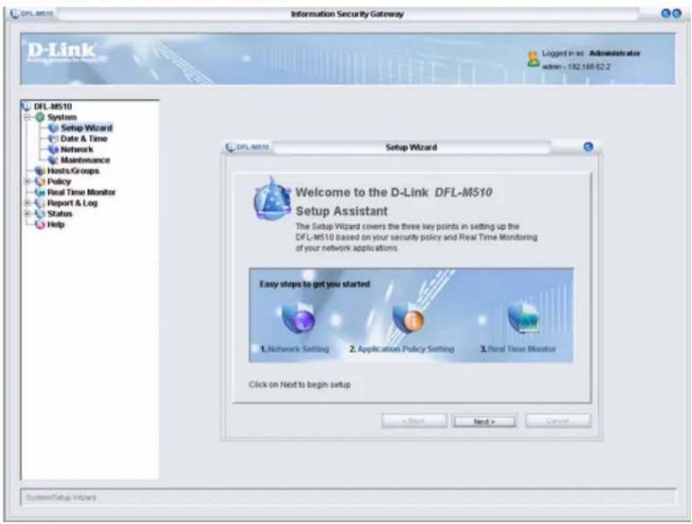
2. Click Next to continue.
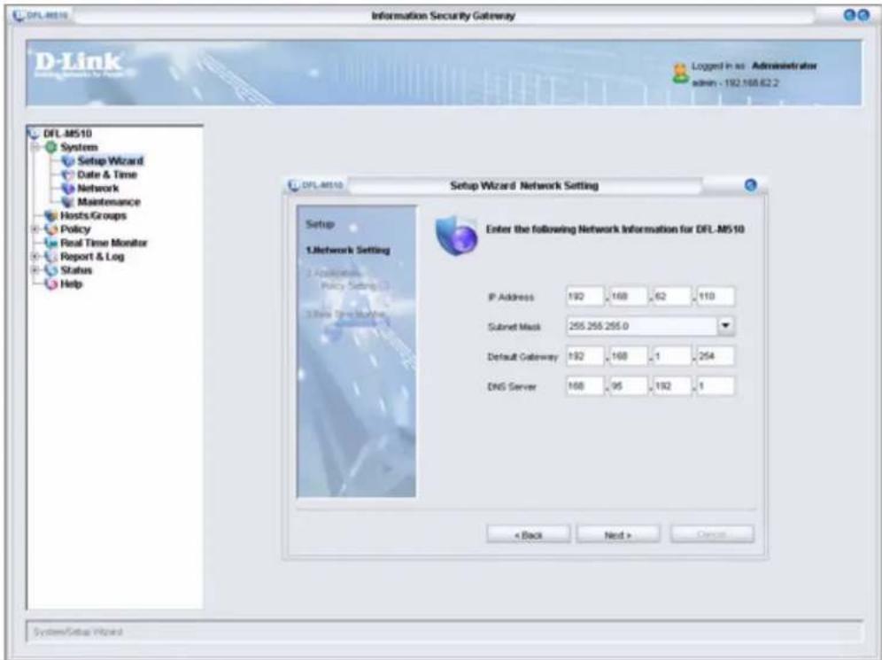
- You need to provide your IP Address, Subnet Mask, Default Gateway, and DNS Server address to enable the device to connect to your network. If the network was set by CLI, check the settings here.
Type in the required information and click Next.
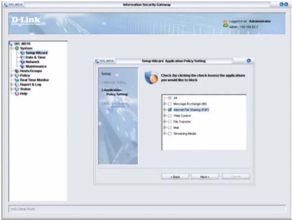
- Select the check boxes for the applications you want to block and click Next.

You can leave all the boxes unchecked to be sure the DFL-M510 is set up correctly. Later you can add applications to be blocked in the Policy menu. See "Chapter 4: Policy" on page 55.
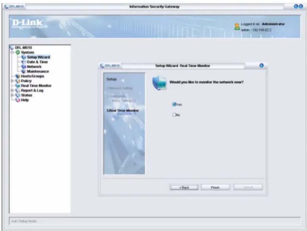
- Select the No radio button and click Finish.

If you select Yes in the screen above, you are taken to the Real Time Monitor screen when setup completes. See "Chapter 5: Real Time Monitor" on page 79.
It takes 30 seconds for the settings to be processed and then the following screen appears:
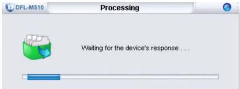
When the setup is successful, the following screen appears:
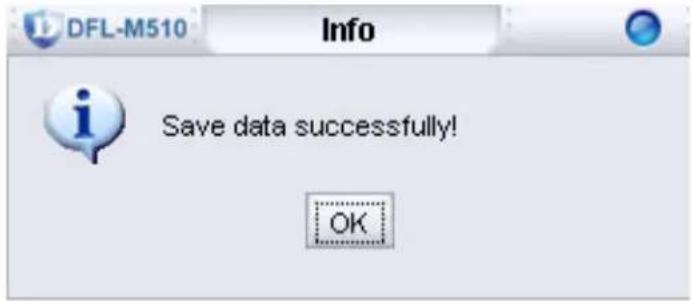
- Click OK. You are returned to the System menu.
The Date & Time Screen
Use Date & Time to adjust the time for your location.
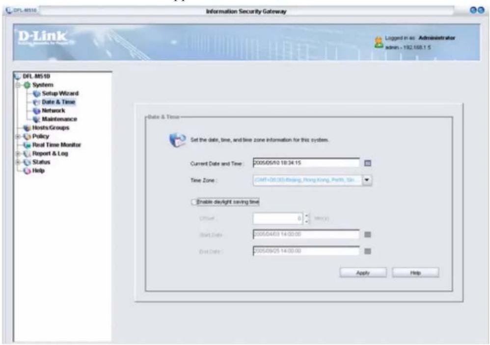
1. Click System > Date & Time.
The Date & Time window appears.
2. Click to the right of Current Date and Time.
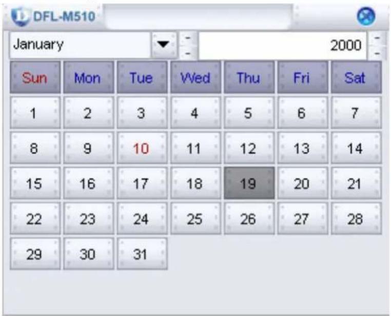
- Select the current date and click 🔒 to return to the Date and Time screen.
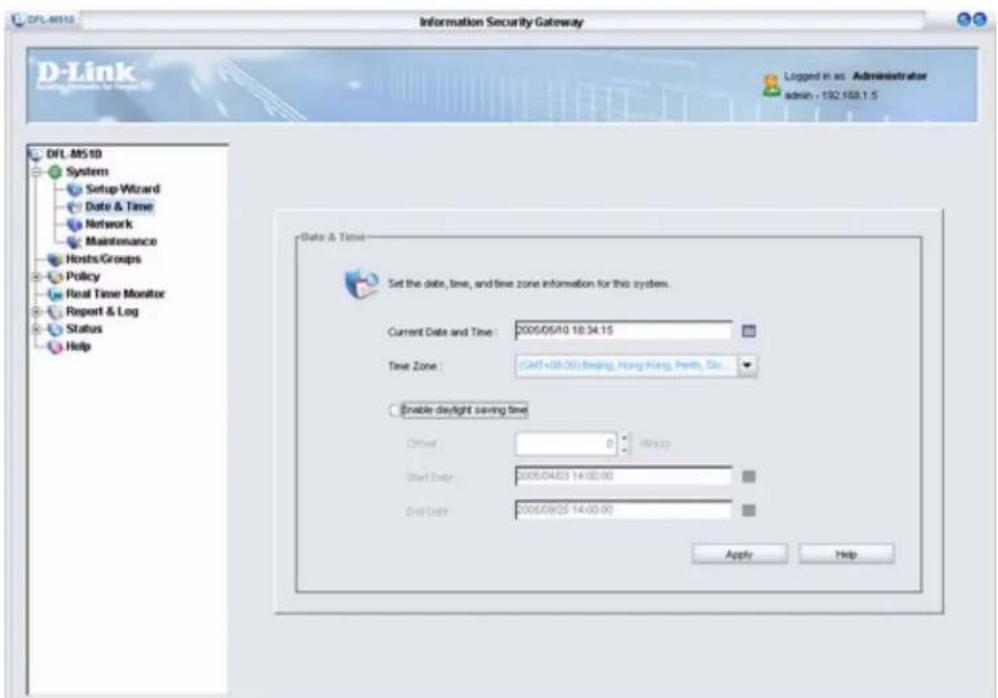
-
In the Current Date and Time field, type in the current time and then choose the time zone for your location from the drop-down list.
-
Click Apply to confirm your settings. The following screen appears:
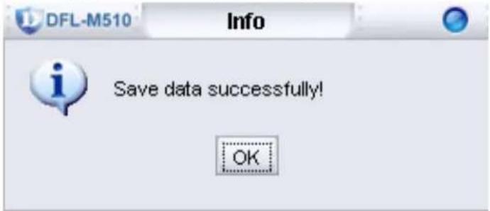
- Click OK to exit.
 | If your location uses daylight saving time:A. Check Enable daylight saving timeB. At Offset, set the offset timeC. Click to set the start and end dates and then click Apply. |
The Network Screen
The Network screen lets you configure settings for your network.
1. Click System > Network.
The Network window appears.
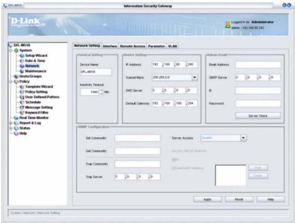
The Network screen has four tabs. Click on a tab to view the settings.
NETWORK SETTING TAB
Click the Network Setting tab. The following screen appears.
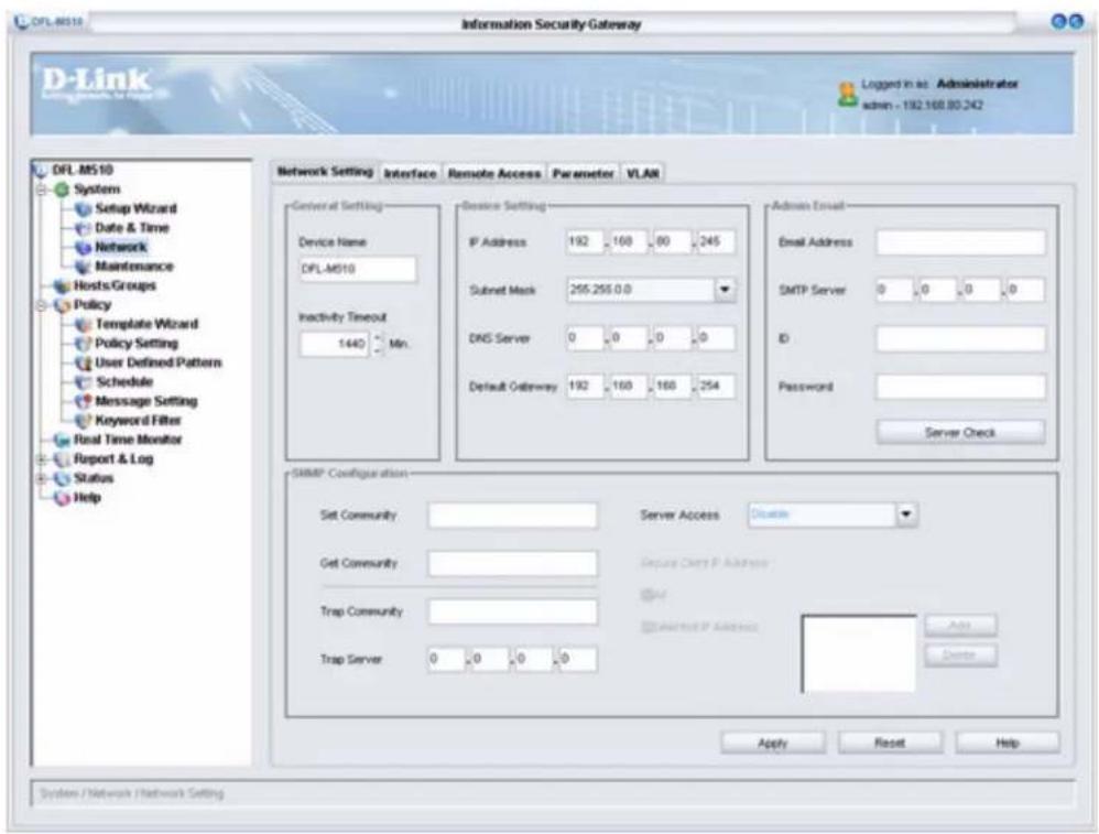
GENERAL SETTING
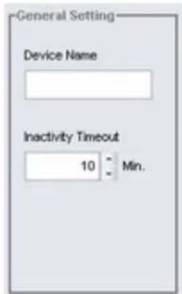
| Device Name Type a | name for the device. |
| Inactivity Timeout Set the inactivity time out. | |

When more than one DFL-M510 is installed in your location, assign device names to help identify different units.
DEVICE SETTING
These fields display the IP address and related network information of the device.
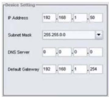
| IP Address Device IP | Address |
| Subnet Mask Device | Subnet Mask |
| DNS Server Device D | DNS Server |
| Default Gateway Device | Default Gateway |
ADMIN EMAIL
To enable the network administrator to receive emails from the DFL-M510, the following fields must be completed.
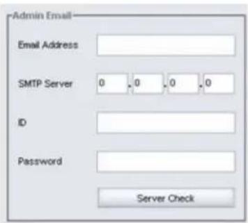
| Email Address Type the administrator's email address | |
| SMTP Server Type the IP of the SMTP server | |
| ID Type an ID if sender authentication is required | |
| Password Type a password if sender authentication is required | |
| Server Check When the above fields are completed,click Server Check to verify the mail account. |

The ID/Password field must be filled in if your mail server requires authentication.
SNMP CONFIGURATION
To set up SNMP (Simple Network Management Protocol), the SNMP communities have to be set and access control to the SNMP server has to be enabled
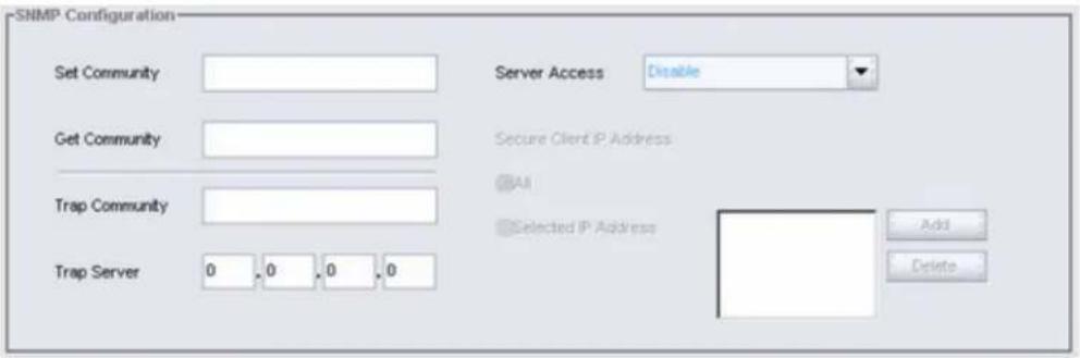
| Set Community Type | the SNMP community that allows the SNMP set command. You can use SNMP software to configure the device such as System Contact, Name, Location. |
| Get Community Type | the SNMP community that allows the SNMP get command. You can use SNMP software to retrieve configuration information from the device such as System description, Object ID, Up time, Name, Location, and Service. |
| Trap Community Type | the SNMP community that allows the SNMP trap command. When the device reboots, the device sends the trap to the trap server. |
| Trap Server Type the | IP of the SNMP management center that should be reported. |
| Server Access Options are:Disable - No access from LAN or WANAll - Access from LAN and WAN (Note: This setting has no remote access restrictions; any IP address will have access to the DFL-M510.)WAN - Access from WAN onlyLAN - Access from LAN onlyThe default option is Disable. | |
| Secure ClientIP Address | Options are All or Selected IP Address, that the SNMP commands are restricted to come from. |
| Add/Delete Use Add/Delete to select IP addresses. | |
Configuring Server Access for LAN and WAN for Specific IP Addresses
- Select All in the Server Access field.
Note: This setting has no remote access restrictions; any IP address will have access to the DFL-M510.
- Click the Selected IP Address radio button and click Add.
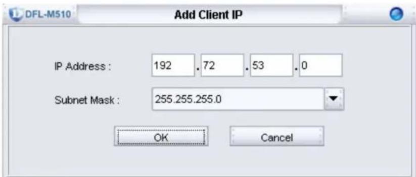
- Type in the IP Address and Subnet Mask for the PC that will access the DFL-M510 and click OK. The IP Address is added to the Selected IP Address window. Repeat steps 2 and 3 to add other IP Addresses.
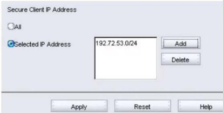
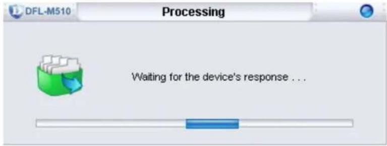
- Click Apply. The new settings are processed.
When the settings are processed, the following screen appears:
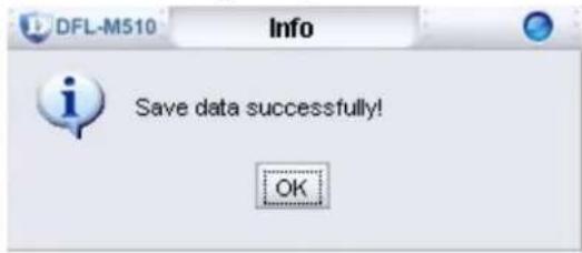
- Click OK to finish.
INTERFACE TAB
Click the Interface tab. The following screen appears.
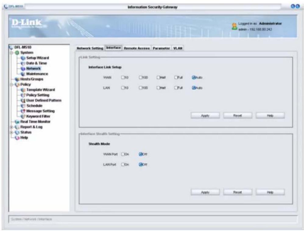
LINK SETTING
Set the Ethernet ports for the speed you want and click Apply.
| Interface Link Setup WAN - 10/100/Half/Full/Auto |
| LAN - 10/100/Half/Full/Auto |
INTERFACE STEALTH SETTING
The LAN/WAN Ports can be configured in Stealth Mode by selecting On.
| Stealth Mode WAN - | On/Off |
| LAN - On/Off | |
| Subnet Mask LAN Port |
After you make changes, click Apply. The new settings are processed and the following screen appears:
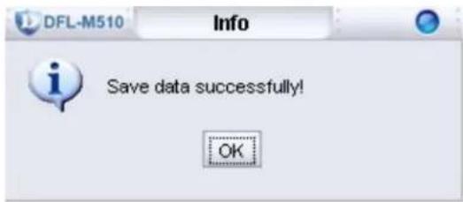
Click OK to finish.
REMOTE ACCESS TAB
Click the Remote Access tab. The following screen appears.
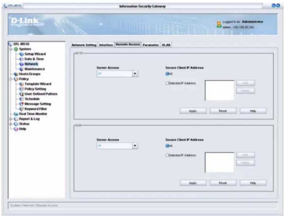
The DFL-M510 can be remotely managed via HTTP or SSH. The Remote Access tab lets you control access rights.
HTTP/SSH
The descriptions for the HTTP and SSH fields are the same.
| Server Access | Options are All, Disabled, Allowed from LAN, or Allowed from WAN. The default is All. |
| Secure Client IP Address | Options are All or Selected IP Address. |
| Add/Delete Use Add/Delete to add IP Addresses or a Subnet address to the Selected IP Address window. | |
Configuring Server Access for SSH for Specific IP Addresses
-
Select WAN in the Server Access field.
-
Click the Selected IP Address radio button and click Add.
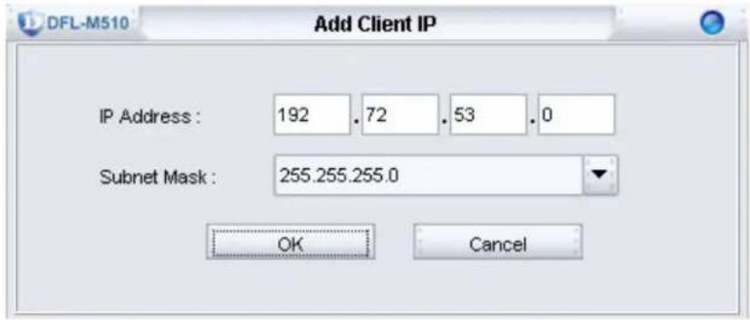
- Type in the IP Address and Subnet Mask for the PC that will access the DFL-M510 and click OK. The IP Address is added to the Selected IP Address window. Repeat steps 2 and 3 to add other IP Addresses.
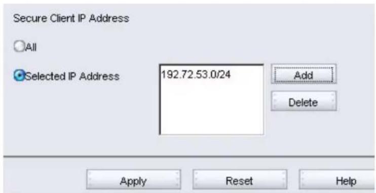
- Click Apply. The new settings are processed.
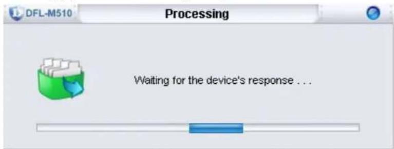
When the settings are processed, the following screen appears:
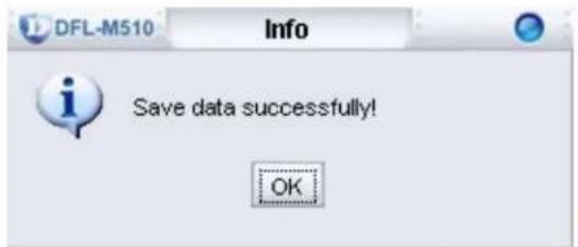
- Click OK to finish.
PARAMETER TAB
Click the Parameter tab. The following screen appears.
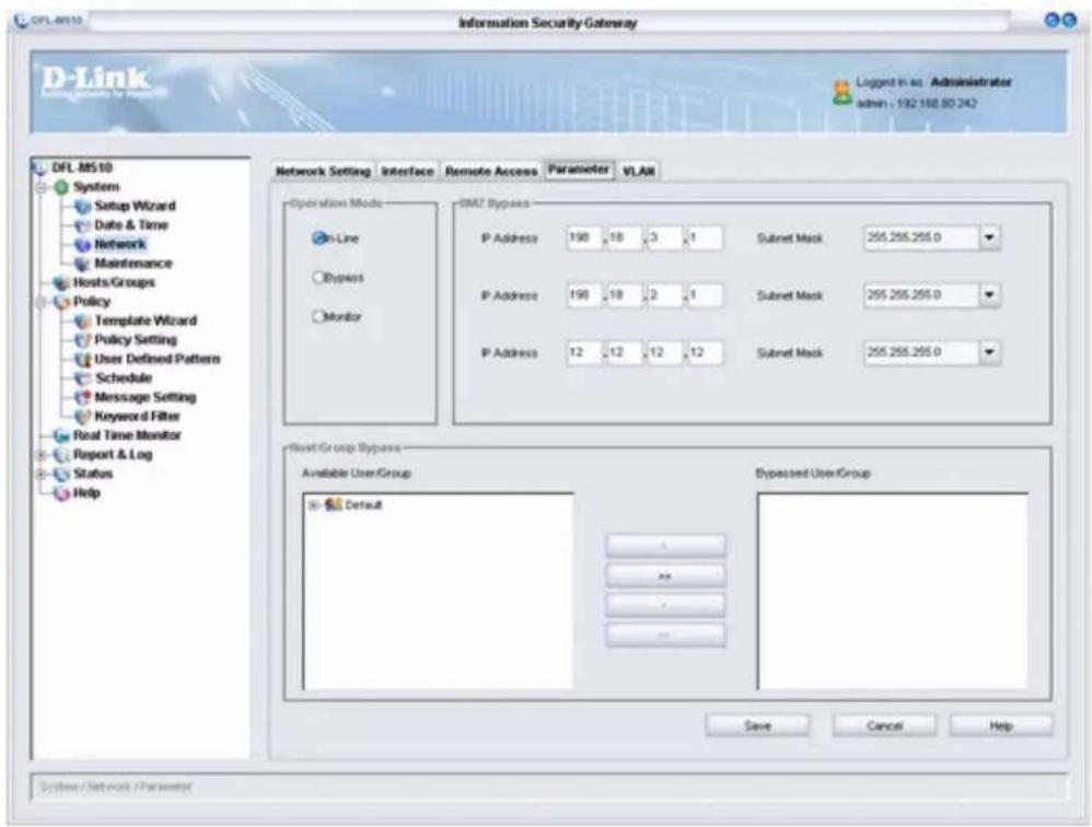
This tab defines management parameters.
OPERATION MODE

The DFL-M510 only protects and monitors your network when set to In-Line mode. The other modes offer limited monitoring and are used for integrating the DFL-M510 smoothly with your network.
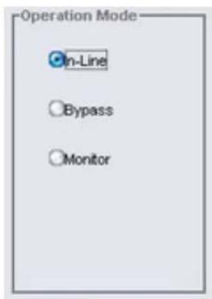
| In-Line | In In-Line mode, the DFL-M510 works as a transparent gateway in your network. All traffic is inspected as it passes through the DFL-M510. The DFL-M510 responds to illegal activities based on policy rules.When attacks are detected, the DFL-M510 can take the following action:Drop the PacketReset the ConnectionLog the EventSave the Packet Message Content |
| Bypass | In Bypass mode, the DFL-M510 works like a bridge with all rules and actions disabled. This mode is designed to help network administrators to debug and trace network abnormalities.When bypass mode is selected, the DFL-M510 will not detect nor take action to security events in the network. |
| Monitor Monitor mode | allows you to analyze network activities and make early-stage diagnosis before deployment. the DFL-M510 will detect all events by inspecting all packets.In this mode, the DFL-M510 will log all events, but will not take any countermeasure (reset, drop actions). It is suggested to monitor network traffic in this mode before setting In-Line mode, in order to fine tune your security policy and network performance. |
DMZ BYPASS
In order to speed up traffic from the intranet to DMZ, hosts within the given DMZ subnet addresses are not checked and all packets from or to those hosts pass unhindered.
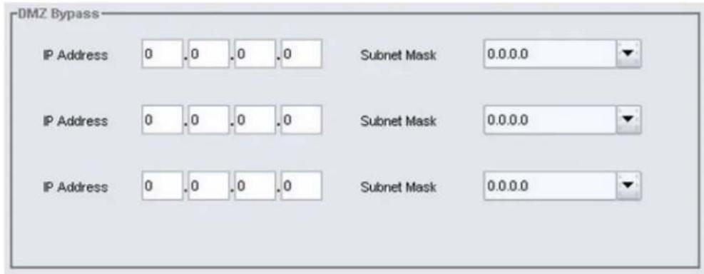
| IP Address Type in the IP Address | |
| Subnet Mask Type in the Subnet Mask |

The IP addresses of the hosts in a subnet must be continuous. That is, the network mask contains only two pairs: the leading 1s, and the following 0s.

DMZ Bypass prevents the DFL-M510 from causing a bottleneck in your intranet. For example, a mail/FTP server could be assigned an IP address in the DMZ Bypass to provide wire speed traffic from the internal network to mail/FTP networks.
Setting Up the DMZ Bypass Function
In the following example, a mail server with the IP address 10.10.10.250 is added to DMZ Bypass.
- Type in the IP address and the Subnet mask of the mail server.
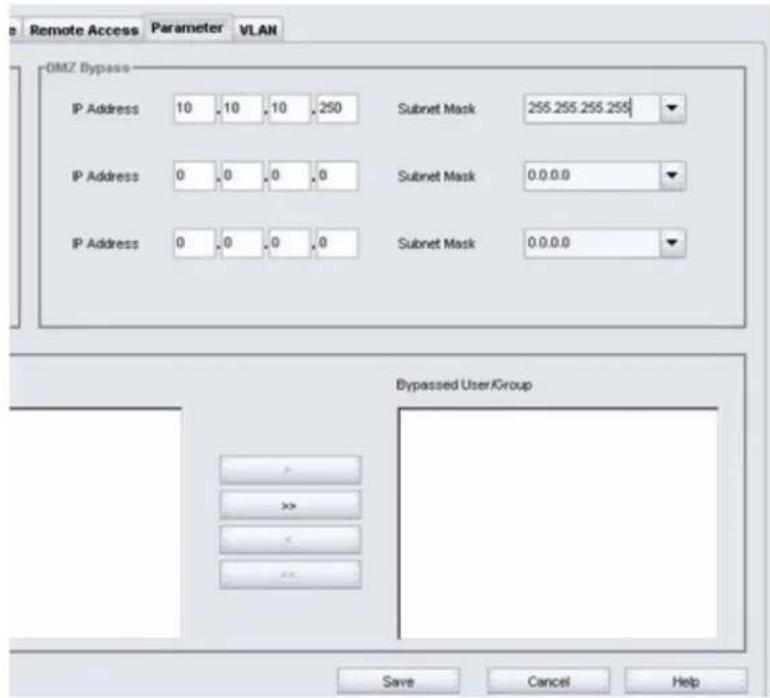
- Click Save.
HOST/GROUPS BYPASS
Hosts within the intranet which do not need to be monitored are added to the Bypassed User/Group. These hosts have unhindered access to the WAN, but may be less secure than In-Line hosts.
 | The IP addresses of the hosts in the bypass list must be in the host table first. That is, the host must be learned or entered before you can select it. Otherwise, the host must be within a group and specified by a subnet. Such a host is automatically added to the bypass list when it is learned. |
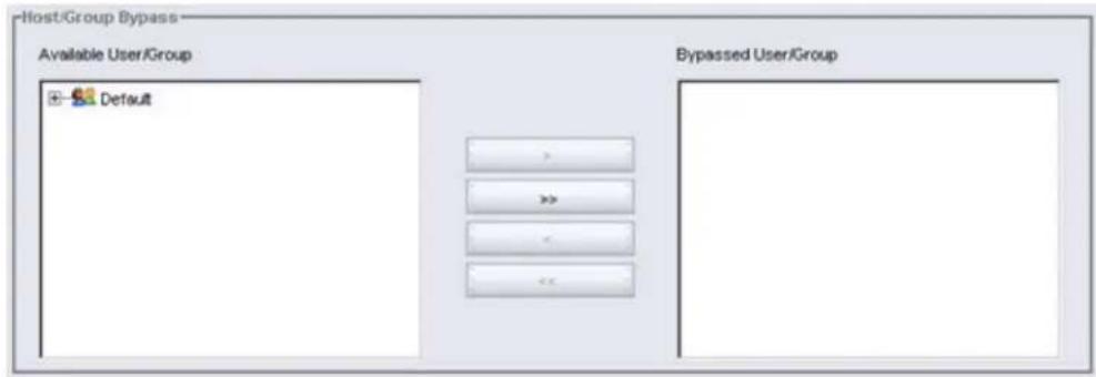
| AvailableUser/Group | Select the User or Group and click >> to add the User/Group to the BypassedUser/Group list. |
| BypassedUser/Group | Lists Users and Groups that have been added. |
After you make changes, click Save. The new settings are processed and the following screen appears:
Click OK to continue.
 | An IP address in the Host Bypass implies bypass source IP. To provide more throughput, you could set up the servers IP (ERP/mail/ftp) in the Host Bypass if the servers are located in the internal network. |
VLAN TAB
Click the VLAN tab. The following screen appears.
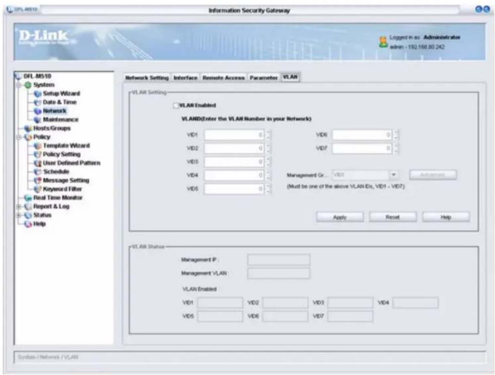
A VLAN (Virtual LAN) is a group of devices on one or more LANs that are configured (using management software) so that they can communicate as if they were attached to the same wire, when in fact they are located on a number of different LAN segments. Because VLANs are based on logical instead of physical connections, they are extremely flexible.
The IEEE 802.1Q standard defines VLAN ID #1 as the default VLAN. The default VLAN includes all the ports as the factory default. The default VLAN's egress rule restricts the ports to be all untagged, so it can, by default, be easily used as a simple 802.1D bridging domain. The default VLAN's domain shrinks as untagged ports are defined in other VLANs.
| Configure VLAN settings before connecting the DFL-M510 to the intranet. |
CONFIGURING VLAN SETTINGS
The following is an example of a network environment with four VLAN sets.
| Item Description | |
| VID1 1 | |
| VID2 3 | |
| VID3 5 | |
| VID4 7 | |
| Management VID2 |
Refer to the following to configure the VLAN setting.
- Click System > Network and then select the VLAN tab.
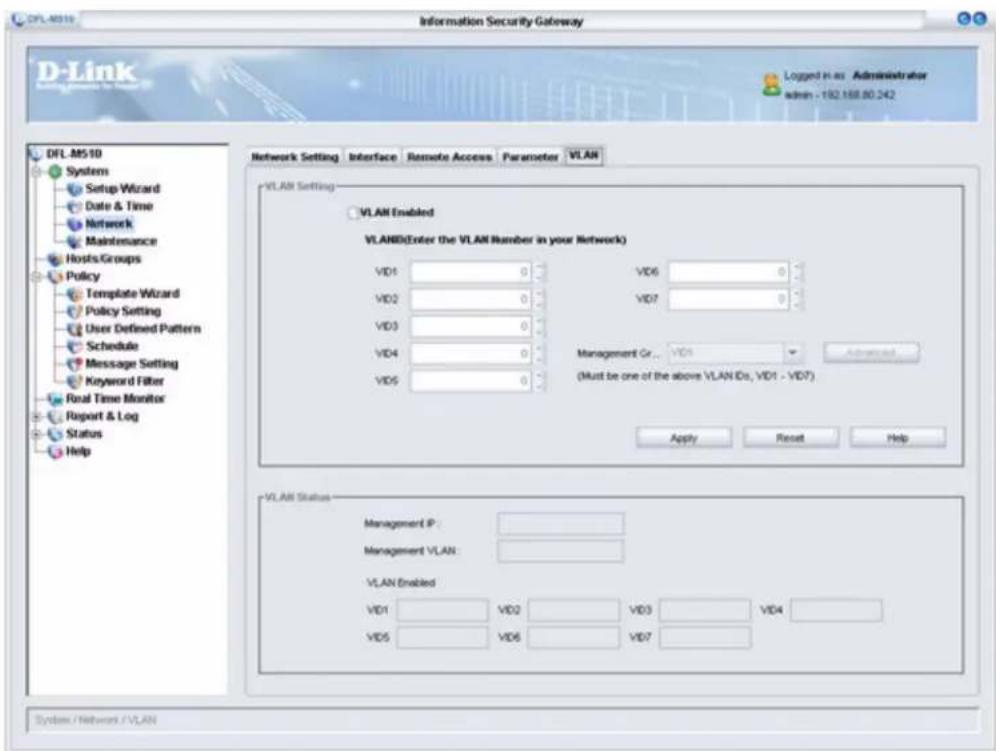
| VLAN Enabled Enables or disables the VLAN function | |
| VID1 - VID7 Type in the VLAN ID. | |
| Management Group | Select the Management VLAN Group |
- Click the VLAN Enabled checkbox to enable VLAN.
- Type in each VID in the VID1 to VID7 boxes.
 | The DFL-M510 supports up to seven VLANs.The Management VID must be either PVID, or VID1 to VID7. Configurations depend on your environment. |
- Click Apply. The screen updates as follows.
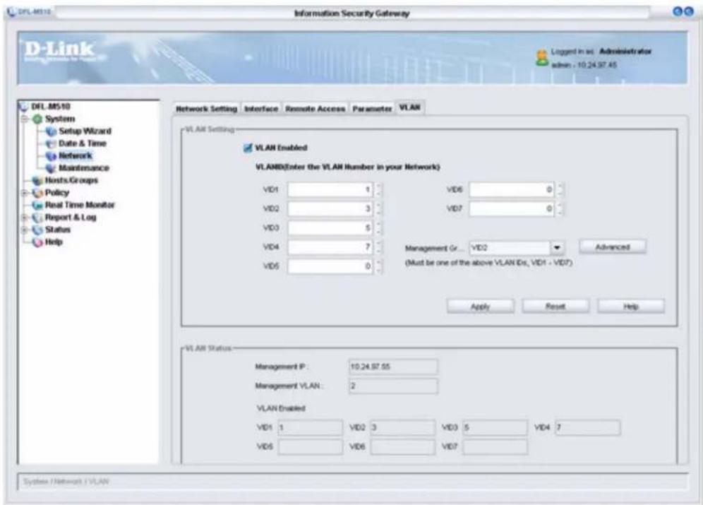
VLAN STATUS
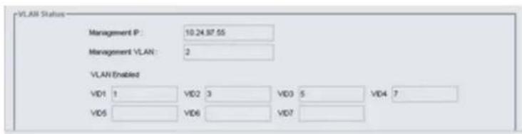
| Management IP Shows the device IP address |
| Management VLAN Shows the Management VLAN Group ID |
| VID1 - VID7 Shows the ID of each VLAN |
The Maintenance Screen
The Maintenance screen lets you carry out network maintenance.
1. Click System > Maintenance.
The Maintenance window appears.
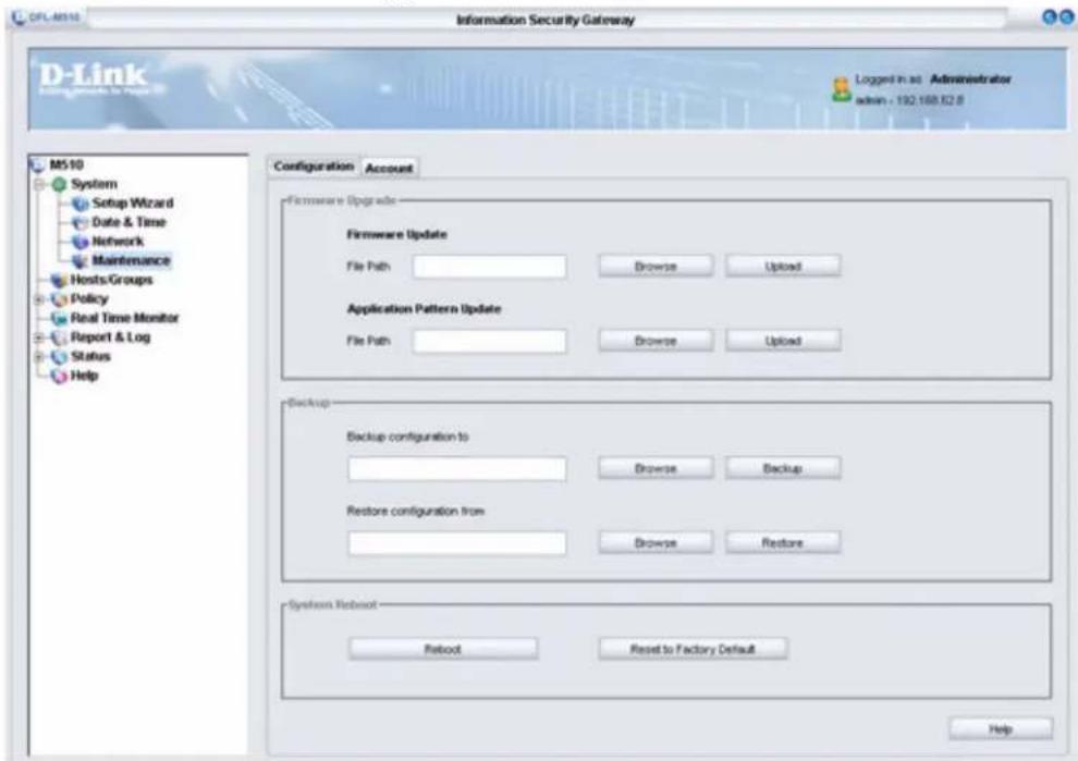
The Maintenance screen has two tabs. Click on a tab to view the settings.
CONFIGURATION TAB
Click the Configuration tab. The following screen appears.
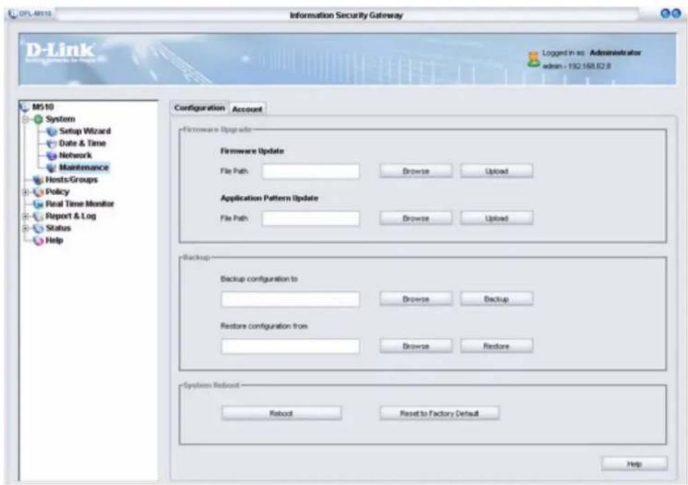
Download the latest firmware file or the application pattern file from D-Link's Web site.
FIRMWARE UPGRADE
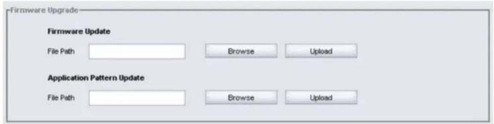
| Firmware/Application Pattern Update | Firmware updates improve or add new functionality. Application Pattern updates improve or add new rules and filters. |
| File Path Type the file path to the update file. | |
| Browse | Press Browse to locate the update file. Then press Upload to send the newest file to the device. |
| Upload | Press Upload to begin the update. |
BACKUP
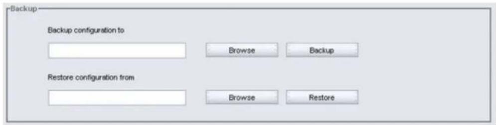
| Backup configuration to | Press Backup configuration to to store the currents settings to a file. The backup configuration dialog displays to ask the name of the stored file. |
| Restore configuration from | Press Restore configuration from to restore setting from a file on the management GUI. The restore configuration dialog would display to ask the name of the file. |
Restoring a Configuration Backup
- Click Browse.
- Locate the DFL-M510.cbk file and click Open.
- Click Backup to send the file to the device.
- When the update completes, click Reboot to reboot the device. (See "System Reboot" on page 42.).
| NOTE | The configuration file includes the user-defined policy. |
SYSTEM REBOOT

| Reboot | After an update completes, press Reboot to boot the device from the new firmware. |
| Reset to Factory Default | Press Reset to Factory Default to restore the factory default settings. |

Rebooting or resetting the device closes the GUI. Log back on as you normally do.
ACCOUNT TAB
Click the Account tab. The following screen appears.
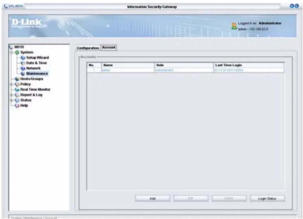
ACCOUNTS
| No. Shows the current number of accounts | |
| Name Shows the name for each account | |
| Role Shows the shows the level of the user's policy: Administrator; Read Only; or Write. | |
| Last Time Login Shows the last time the account was accessed |

Only users that are assigned the Administrator role can edit the Account and Hosts/Groups menus.
Creating a New Account
To create a new account click Add. The Account Edit dialog box appears.
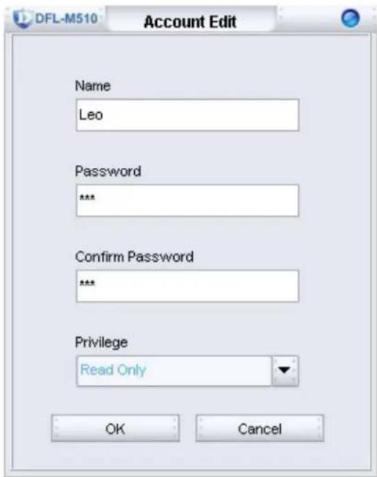
| Name Type a name for the account. | |
| Password Type a password. | |
| Confirm Password Retype the password. | |
| Privilege | Assign privilege status: Administrator; Read Only; or Write. |
Click OK to confirm. The account is added to the Accounts list.
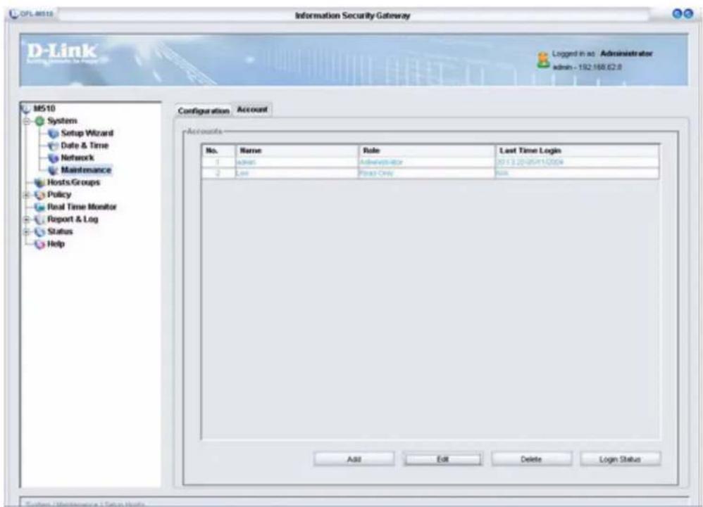
To review or audit an account, click Login Status. The following screen appears:
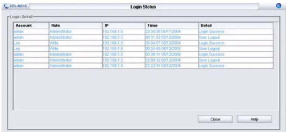
A log is created each time a user logs on or logs out. Monitor this list for added security. See “The Log Tab” on page 94.
A host is a client computer with a network interface. A group is a set of hosts. The DFL-M510 learns host information from packets passing through the device. Host information includes the MAC address, IP address and VLAN address. In order to manage the host internet access, we can lock a host with a MAC address and/or an IP address.
Assign names to hosts to make them easier to manage. Otherwise, the DFL-M510 learns the device name from the network. Assigned names take priority over learned names.
The Host/Groups Screen
After you log on, click Host/Groups to open the following screen:
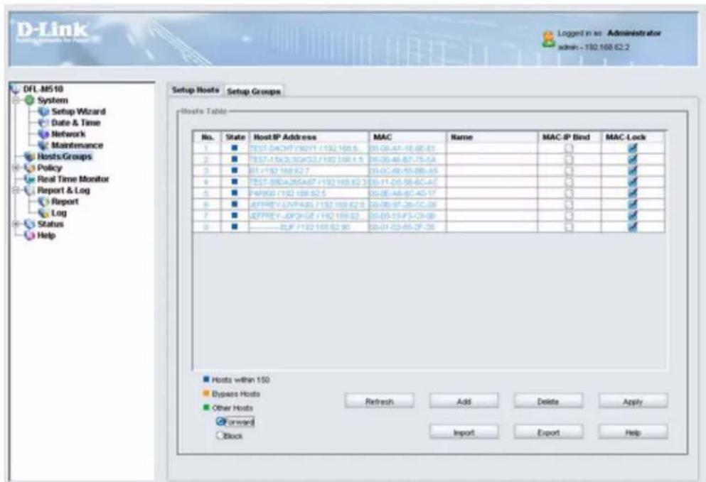
The Host/Groups screen has the following two tabs:
• “The Setup Hosts Tab” on page 47
• "The Setup Groups Tab" on page 51
THE SETUP HOSTS TAB
The Setup Hosts tab lets you add new hosts and manage current hosts.
- To view the Setup Hosts tab, click Hosts/Groups > Setup Hosts.
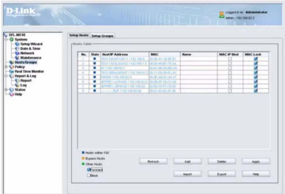
| No. Shows the current number of hosts | |
| State Shows the status for each host (refer to color legend at the bottom of the screen) | |
| Host/IP Address Shows the host IP address | |
| MAC Shows the host MAC address | |
| Name Shows the host name | |
| MAC-IP Bind Check this box to lock an IP address to the host's MAC address | |
| MAC-Lock Check this box to lock the MAC address | |
| Hosts within 150 Hosts all within 150 hosts | |
| Bypass Hosts Hosts that are not monitored | |
| Other Hosts The DFL-M510 can manage 150 hosts. If you select Block, hosts that exceed 150 have no Internet access. If you select Forward, those hosts will have Internet access but will not be monitored by the DFL-M510. |
CHANGING THE STATUS OF A HOST
In the following example, the status of No. 50 is changed from Hosts within 150 to Other Hosts.
- Right-click on the host you want to change the status of.
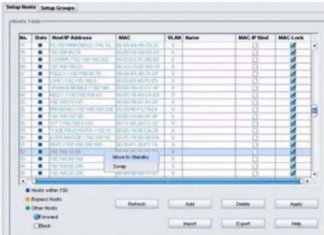
- Select Move to Standby.
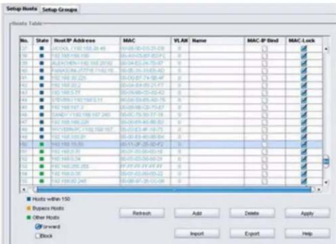
Notice, the State icon is now green, indicating the host is now in the Other Hosts category.
ADDING A HOST
Refer to the following to add a host.
1. Click Add.
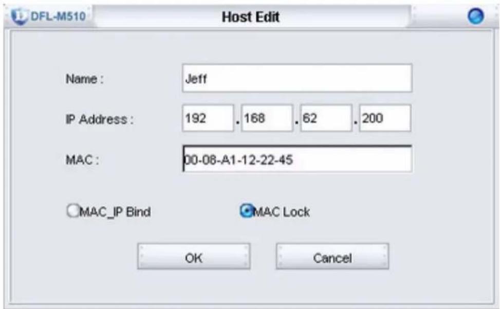
- Type in the required information and click OK. The new host is added to host table.
| No. | State | Host/IP Address | MAC | Name | MAC-IP Bind | MAC-Lock |
| 1 | ■ | TEST-04CHYV6011 /192 168 6 | 03-06-A3-18-08-21 | ☐ | ✓ | |
| 2 | ■ | TEST-01XQ50403 /192 168 1 5 | 03-00-48-82-75-5A | ☐ | ✓ | |
| 3 | ■ | BT (192 168)2 7 | 03-02-A8-56-88-45 | ☐ | ✓ | |
| 4 | ■ | TEST-08EA265A57 /192 168 42 3 | 03-11-49-95-97-42 | ☐ | ✓ | |
| 5 | ■ | PARW0/192 168/42 5 | 03-06-A5-57-43-17 | ☐ | ✓ | |
| 6 | ■ | BFPREV-U/PRA95 /192 168 42 9 | 03-08-07-26-02-08 | ☐ | ✓ | |
| 7 | ■ | BFPREV--BFPV436 /192 168 42 | 03-05-15-F3-C9-D5 | ☐ | ✓ | |
| 8 | ■ | ——— B.P. /192 168 42 50 | 03-01-03-05-37-30 | ☐ | ✓ | |
| 9 | ■ | 192 168 42 300 | 03-08-A3-12-22-45 | alt | ☐ | ✓ |
EXPORTING A HOST DATABASE
You can export a host database to reuse or to import into another DFL-M510. Refer to the following to export a host database.
1. Click Export.
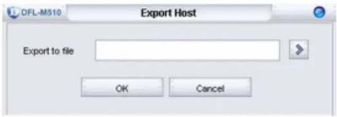
- Click . The Save dialog box appears.
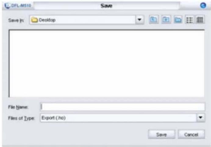
- Enter a file name and click Save.
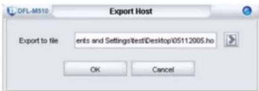
- Click OK to confirm the export.
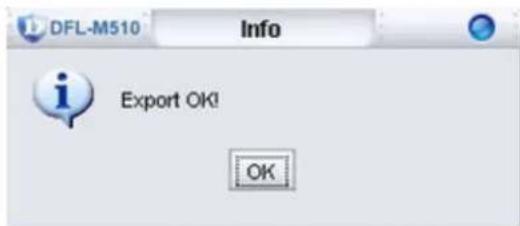
- Click OK to continue.
THE SETUP GROUPS TAB
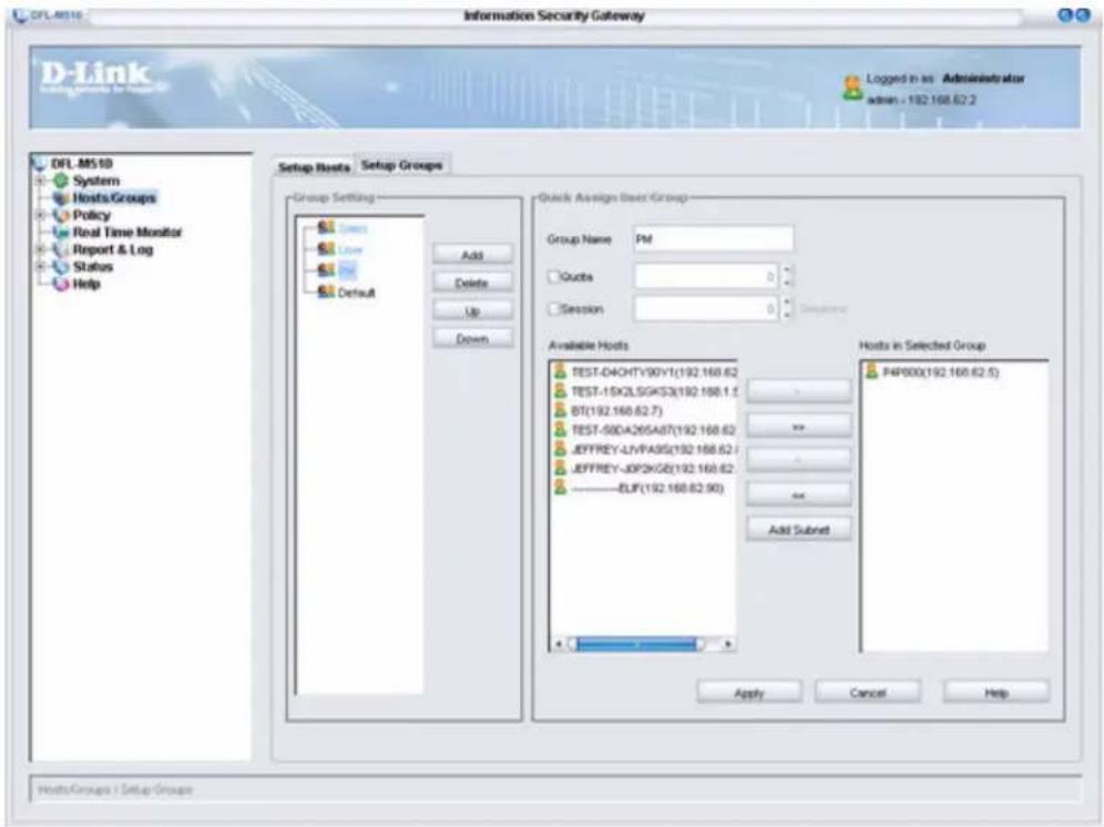
There is one Default Setup Group in the DFL-M510. The Setup Groups tab lets you add and configure additional Setup Groups.
- To view the Setup Groups tab, click Hosts/Groups > Setup Groups.
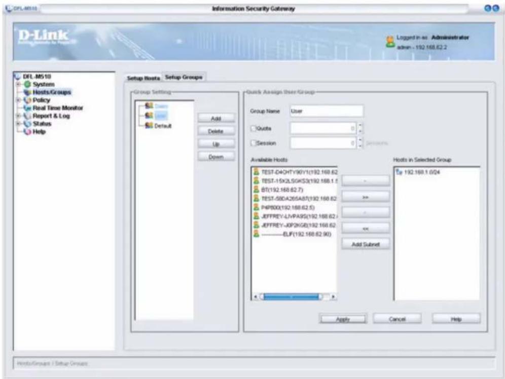
GROUP SETTING
| Add Click to add a new Setup Group | |
| Delete Click to delete a Setup Group | |
| Up Click to move a Setup Group up | |
| Down Click to move a Setup Group down |
QUICK ASSIGN USER/GROUP
| Group Name Type in | the group name |
| Quota Total available | space to a group |
| Session Total sessions | available to a group |
| Available Hosts Lists | the available hosts |
| Hosts in Selected Group | Lists the hosts in the selected group |
| Add Subnet Click to add a sequential IP address range to a group. |
Assigning Hosts to Groups
You can assign a host to a group by checking the button crossing the host and the group. Refer to the following to add a host to a group.
1. Click Add.
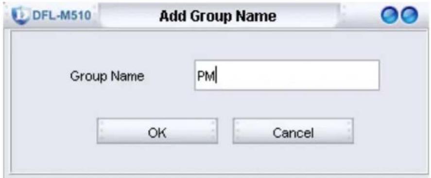
2. Type a group name and click OK.
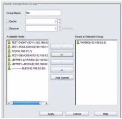
- Select the host and click to add it to the Hosts in Selected Group window.
- Click Apply.
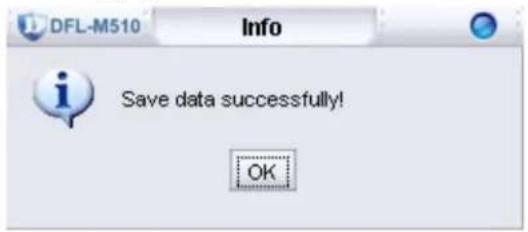
- Click OK to finish. The new group is added to the Group Setting list.
CHAPTER 4: POLICY
Policy is the most important information in the DFL-M510 Management System. A policy can consist of thousands of patterns. Each pattern defines how to detect an application, how to respond when an application is detected, what to block, and when to block. You can view and modify the settings, including applying scope, acting schedule, actions and information such as category, and constraints.
The Policy Screen
After you log on, click Policy to open the following screen:
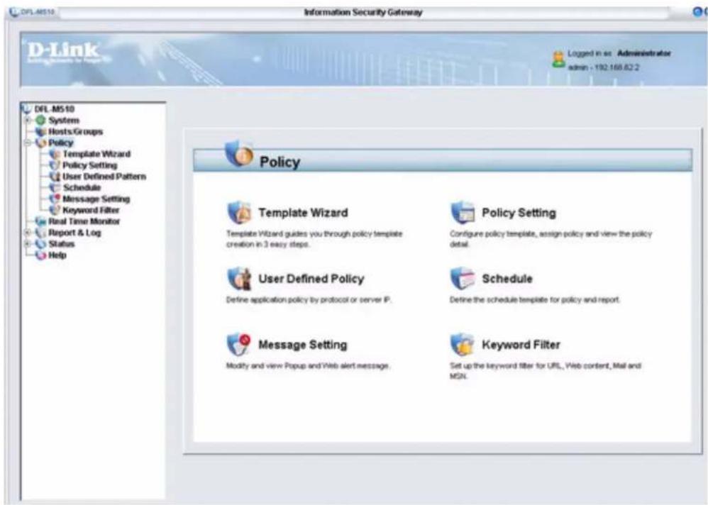
The Policy screen gives you access to the following screens:
- “Running the Template Wizard” on page 56
• “The Policy Setting Screen” on page 58 - "User Defined Pattern" on page 68
• "The Schedule Screen" on page 72 - "Message Setting" on page 74
- "Keyword Filter" on page 76
After the policy database is published and fetched, it is uploaded to the DFL-M510. To manage the users and applications, policies are defined and each of them complies with a company policy. Then each policy can be applied to a host or a group. We define a policy before applying it or creating a template. A template can be defined manually or via the template wizard. Once a template is defined, it can be assigned to a host or a group and it becomes a complete policy.
Running the Template Wizard
The Template Wizard helps you to quickly set up a policy template. Refer to the following to run the Template Wizard.
1. Click Policy, Template Wizard.
The Template Wizard window appears.
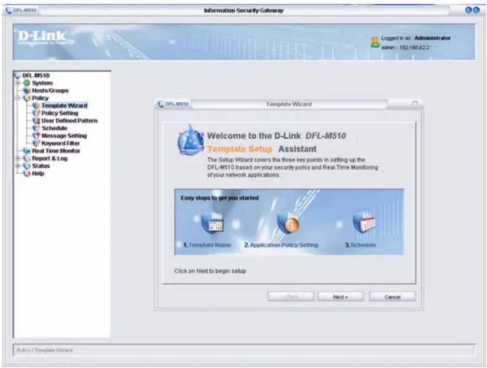
2. Click Next to continue.
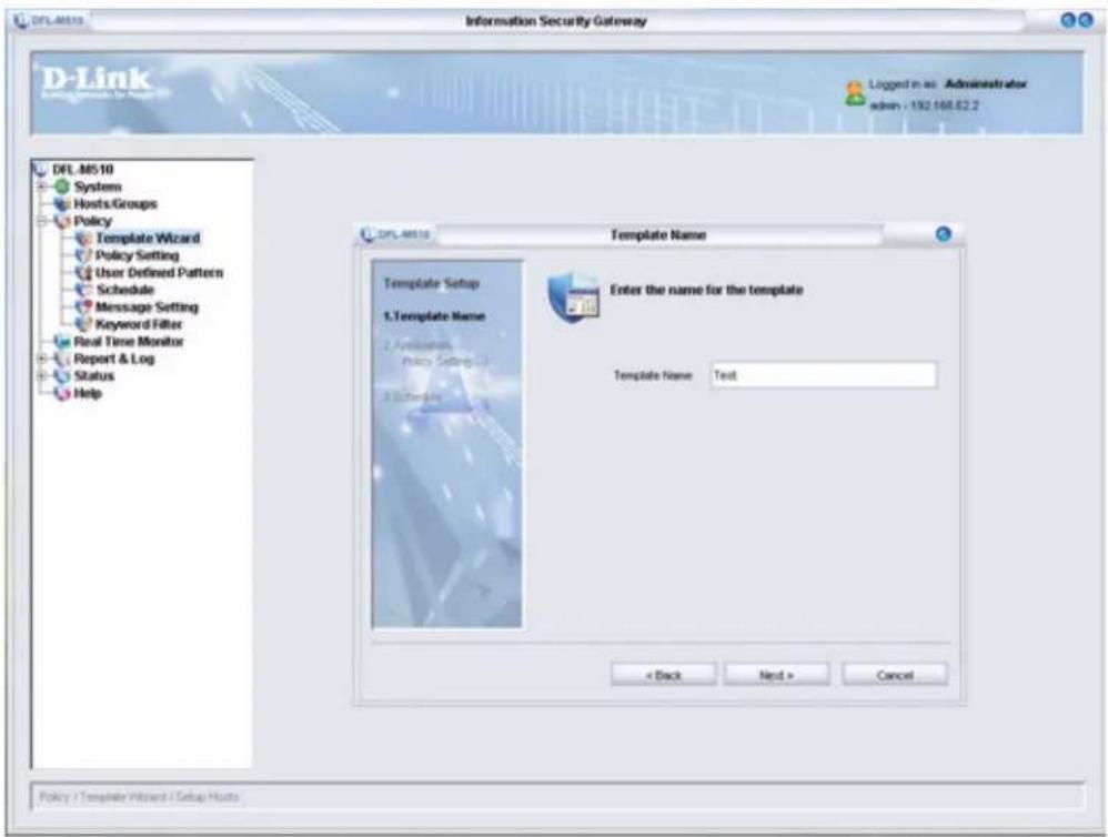
3. Type a name for the template and click Next.
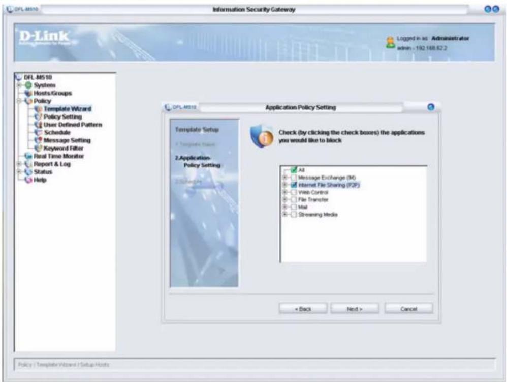
- Select the applications that you want to block. (If you check the Internet File Sharing (P2P) check box, all P2P applications are blocked. You can modify these settings later. See “The Assign Policy Tab” on page 66.) And then click Next.
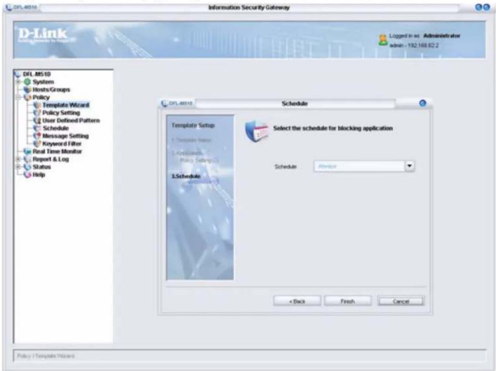
- Click the drop-down arrow at Schedule and select a schedule for the template. (You can change this setting later. See "The Schedule Screen" on page 72.) And then click Finish. The settings are processed and when the setup is successful, the following screen appears:
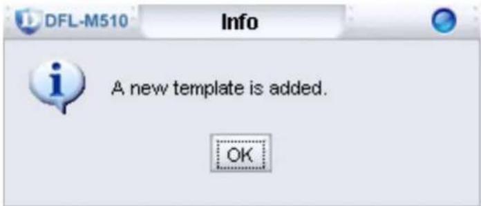
- Click OK to exit the Setup Wizard.
The Policy Setting Screen
After you log on, click Policy/Policy Setting to open the following screen:
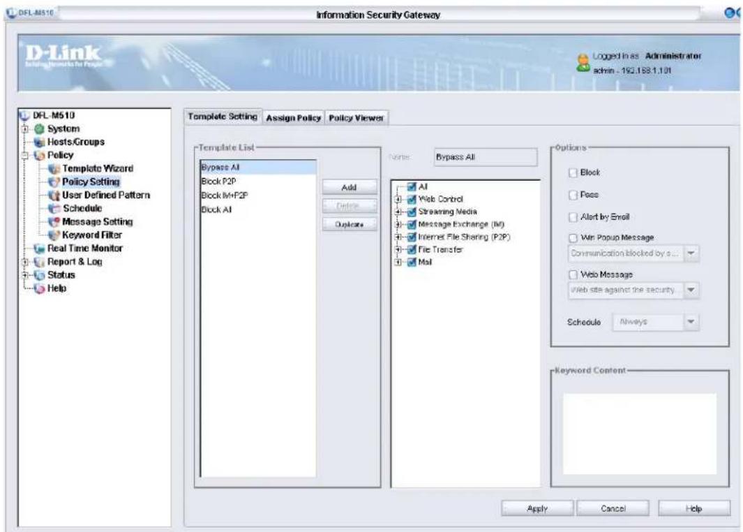
Every template, including the global template created by the device wizard, can be created or modified.
The protocols displayed on the policy are described as follows.
A. The IM/Remote Access Application that can be managed by the DFL-M510
| Item Protocol Management | Type Support Version | ||
| Message Exchange (IM) | MSN MSN Keyword | File Transfer Chat Login Online Game Audio Communication Video Communication | 7.0(Build 7.0.0813) |
| ICQ Chat | File Transfer Login Audio Communication Video Communication | ICQ5 | |
| AIM Chat | File TransferLoginAudio CommunicationVideo Communication | 5.9.3759 | |
| iChat Chat | File TransferLoginAudio CommunicationVideo Communication | 2.1 | |
| Yahoo Messenger | File TransferLoginChatAudio CommunicationVideo Communication | 6.0.0.1921 | |
| QQ Login | File Transfer | QQ2005 | |
| TM Login | File Transfer | TM2005Beta1 | |
| Skype Login 1.3 | 0.51. | ||
| IRC Login | File Transfer | MIRC 6.16 | |
| Odigo Login v4.0 | Beta(Build 689) | ||
| Rediff BOL Login | ChatAudio CommunicationFile Transfer | 7.0 Beta(Build 175) | |
| Web Control | Web Application | Web Page KeywordURL KeywordUploadWeb PostDownloadJava AppletCookie | -- |
| Mail SMTP Mail Attached File | Connect | -- | |
B. The P2P/Remote Access Application that can be allowed/blocked by the DFL-M510
| Item Protocol Software Version | ||
| Internet File Sharing (P2P) | EzPeer EzPeer 1.9 | |
| Kuro Kuro 6.0 | ||
| eDonkey2000 eMule 0.46a eDonkey 1.3 mldonkey 2.5.x eMule Plus 1.1d amule 2.0.3 Morpheus 5.0 beta eMule Morphxt7.1 Gnutella Gnutella 2.2.0.0 Bearshare Lite 5.0.1 Morpheus 5.0 Beta Shareaza 2.1.2.0 beta Xnamp 2.5.3 | ||
| FastRack Kazaa Lite Resurrection 0.0.7.6.E Kazaa Lite Tool K++ 2.7.0 beta 1 Kazza 3.0 Grokster 2.6 mldonkey 2.5.x | ||
| BitTorrent BitTornado 0.3.12 BitComet 0.59 BitTorrent Experimental 3.2.1 beta 2 Shareaza 2.1.2.0 beta BitTorrent 4.1.2 beta mldonkey 2.5.x | ||
| DirectConnect PeerWeb DC++ 0.205 DC++ 0.674 DirectConnect 2.205 | ||
| PiGO PiGO V 3.0 | ||
| PP365 PP365 V2004 | ||
| WinMX WinMX 3.53 | ||
| PC Anywhere PC Anywhere 11 | ||
| VNC VNC Ver. 3.37 | ||
| SoftEher SoftEher Ver. 2.0 | ||
| Web Mail Yahoo Mail -- | ||
| File Transfer FTP Application File Transfer Command Execution | ||
| Getright 5.2d | ||
| POP3 | -- | |
| IMAP4 | -- | |
| NNTP -- | ||
| Streaming Media | Realone 10.5 | |
| MS Media Player 10.0 | ||
| H.323 -- | ||
| iTunes 4.8 | ||
| Winamp 5.09 | ||
| Player365 -- | ||

The DFL-M510 manages P2P downloads by using P2P Protocol. In this architecture, no matter what version of client is used, the DFL-M510 can manage it.

The DFL-M510 only supports HTTP downloads via Getright.
The Policy Setting screen has the following three tabs:
- “The Template Setting Tab” on page 63
• “The Assign Policy Tab” on page 66
• “The Policy Viewer Tab” on page 68
THE TEMPLATE SETTING TAB
To view the Template Setting tab, click Policy > Policy Setting > Template Setting.
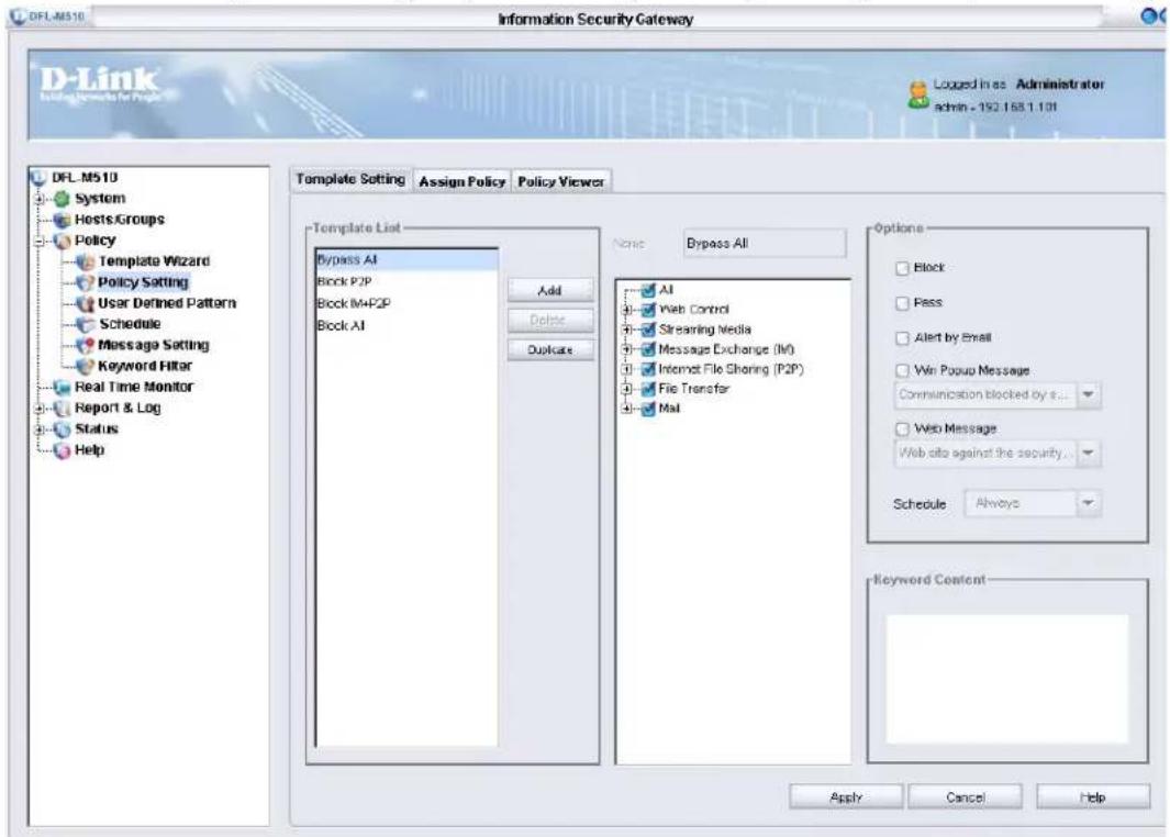
When you select a template from this list, its patterns are listed in the center pane. You can add, delete, and duplicate templates.
| To quickly make a new template, find an existing tem-plate that has a similar pattern and duplicate it. Then modify the new template as desired. |
Each time only one category, application, or pattern can be chosen and settings are shown in the Options pane. When a category is chosen, the options or the constraints show that all patterns of the category are the same. When an application is chosen, the options or the constraints show that all patterns of the application are the same. When a pattern is chosen, it shows all the options and all the constraints of it. The options or constraints which are not shown are grayed out.
Changes made in the fields under Options apply to all patterns.
THE OPTIONS PANE
When a pattern is detected, the DFL-M510 takes certain management actions, such as blocking the connection, or notifying the administrator. There are five actions that can be taken:
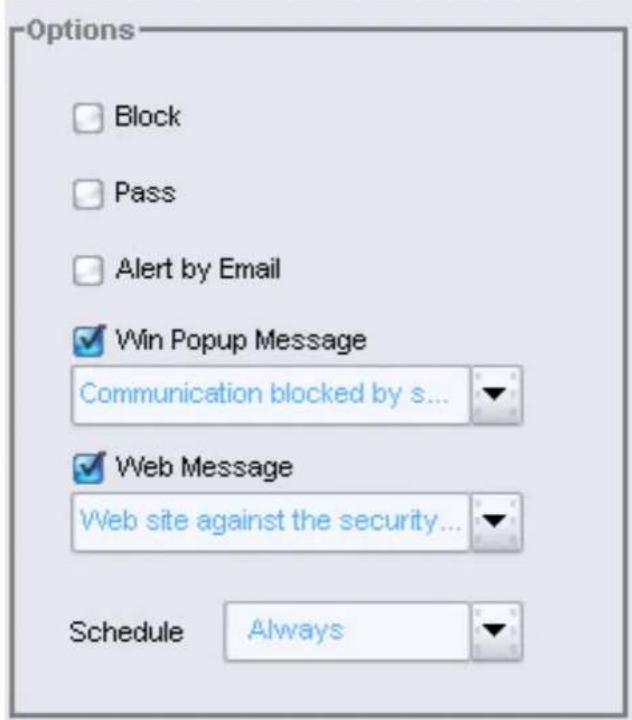
| Action Description | |
| Block The pattern packet | is dropped and its connection cut off. |
| Pass Just log the event. | |
| Alert by Email An email | with details of the attack to the administrator defined in email management parameter. |
| Win Popup Message Send a Windows popup message to the user. | |
| Web Message Send a message to the user and cut the web connection and replace it with a web page. | |

When you turn off Messenger Service or enable Personal Firewall, the Win Popup Message function works correctly.
DEFINING THE ACTIVE SCHEDULE
It is possible to define the active time range of a pattern. The default setting is Always (all the time).
The Scope confines the detection ranges of a pattern rule to some hosts or some directions of traffic. This is very helpful for users who need to fine tune the policy so as to match their environment. For example, if you want to block your staff using P2P software, you can limit the detection
range of the P2P policy to only intranet, and skip detection against DMZ. Thus, false-positives can be reduced, while maintaining performance.
If the detection scope is defined as Directional, the scope is distinguished by source and destination.
If it is defined as Non-directional, the rule will manage. Therefore, an administrator does not have to choose the detection scope from the combo box. Instead it is fine tuned before the policy database is published. The only thing the administrator needs to do is to apply the templates or the policy to the hosts or the groups.
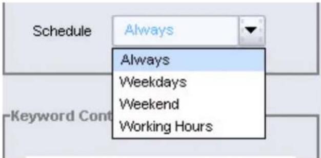
| NOTE | Only schedules already defined show in the combo box. If you want to use custom schedule, you need to define it first. See "The Schedule Screen" on page 72. |
DEFINE KEYWORD CONTENT
Some patterns have constraint parameters. If such a pattern rule is selected, there is a constraint parameter section as following.
Keyword: The user defined keyword to match the content of packets.
THE ASSIGN POLICY TAB
To view the Assign Policy tab, click Policy > Policy Setting > Assign Policy.
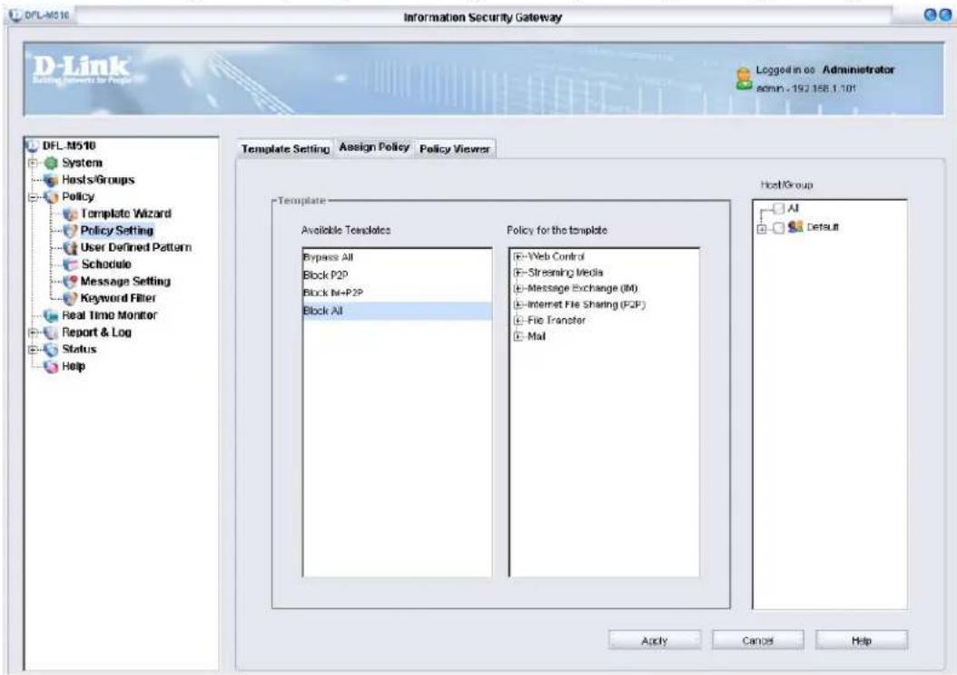
How to Assign a Policy
In the following example, the Security group is assigned a policy only allowing Web control such as Web browsing.
- In the Template Setting tab, click Add to add a new template.
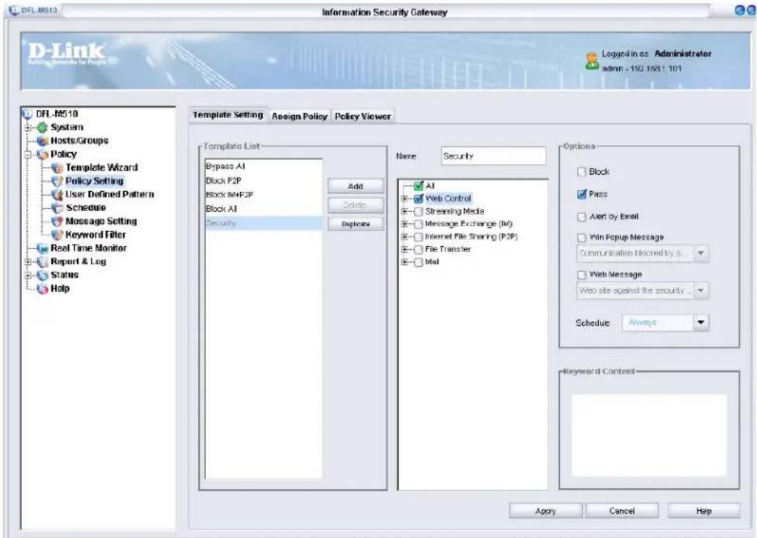
- Click the Assign Policy tab.
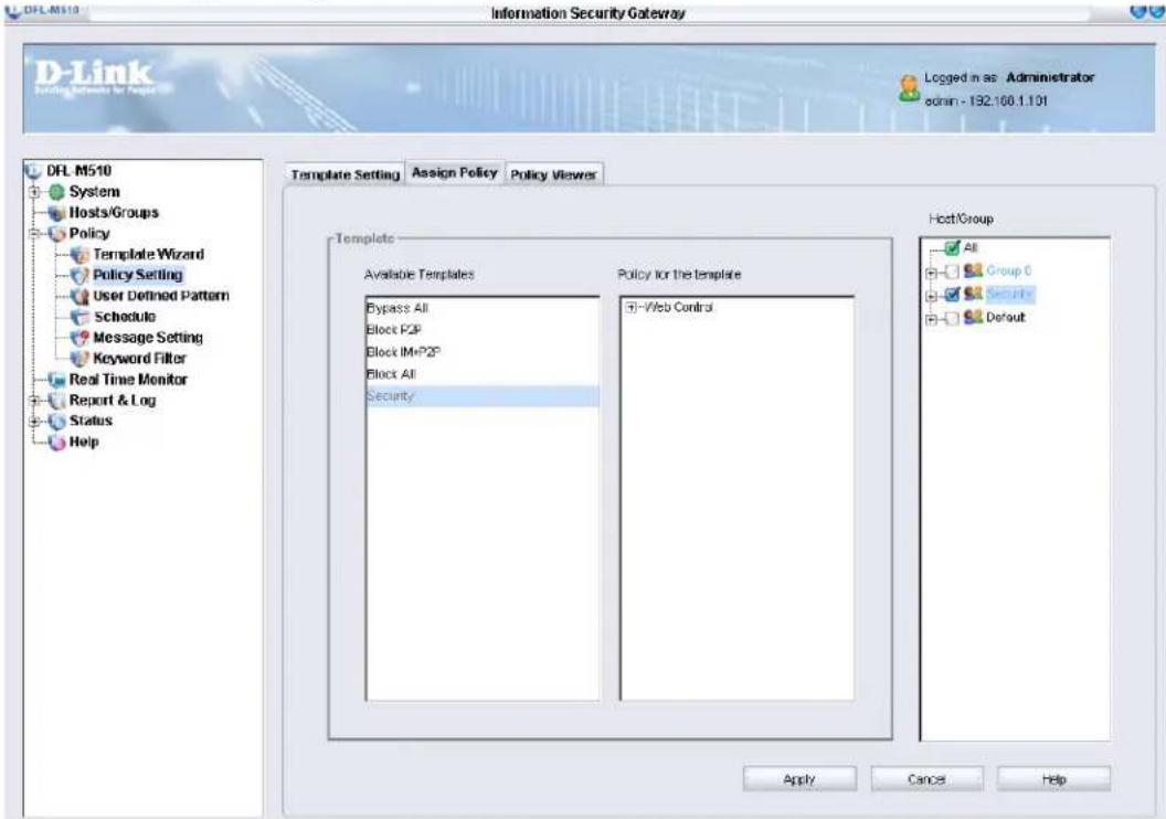
- Select the template from the Available Templates pane and then select the policy you want from the Policy for the template pane.
- Under Host/Group, select Security and click Apply.
THE POLICY VIEWER TAB
In the Policy Viewer tab, you can view all policies of groups. In the example below, we check the policy of the Security group. To view the Assign Viewer tab, click Policy > Policy Setting > Policy Viewer and then select Security in the Host/Group pane.
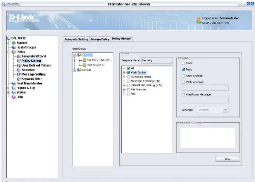
User Defined Pattern
The pattern database is made by a team of professional signature researchers. They are familiar with protocols, system vulnerability, and application patterns.
After a new application pattern is detected, the pattern is put into the pattern database and published. Before publishing, there are still ways for a manager to define application patterns. If a specific application is always connecting to several specific servers or by several specific ports. The servers and the ports can be blocked by a user-defined pattern.
Policies can be defined in the following Policy/User Defined Policy screen:
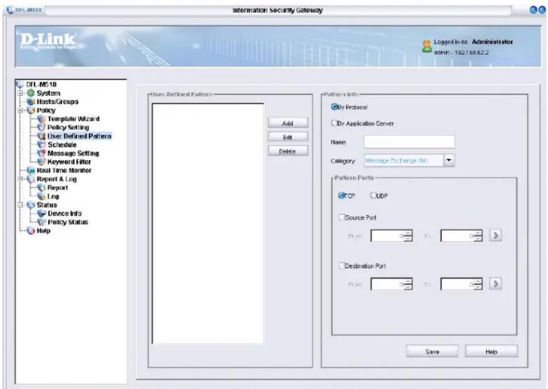
After a pattern is defined, the pattern is displayed in the pattern list, contained in a template, and assigned with options and constraints. Click Edit to edit a defined rule. Click Delete to delete a defined rule.
DEFINING A PATTERN BY PROTOCOL
For example, a Streaming Media sees TCP 3001 ports to connect to Media servers. To block this Streaming Media game do the following.
1. In the User Defined Pattern screen, click Add.
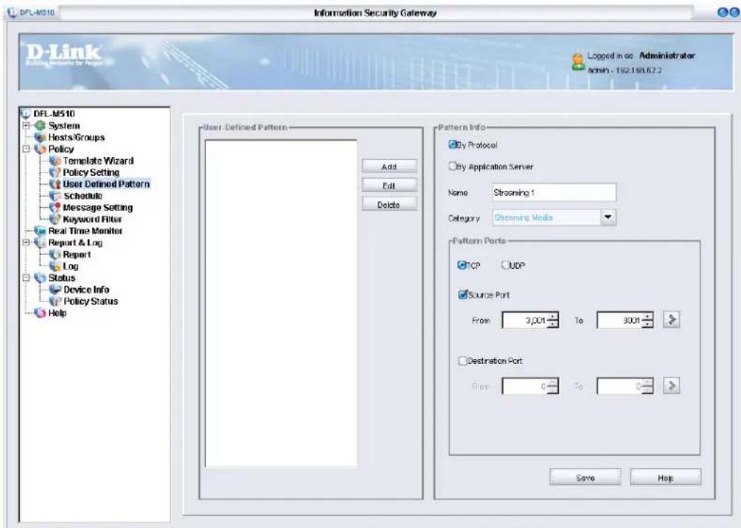
2. Type in Streaming1 for the pattern name and click OK.
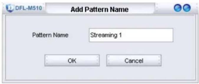
- Input a pattern named Streaming 1, with category Streaming Media and TCP port 3001.
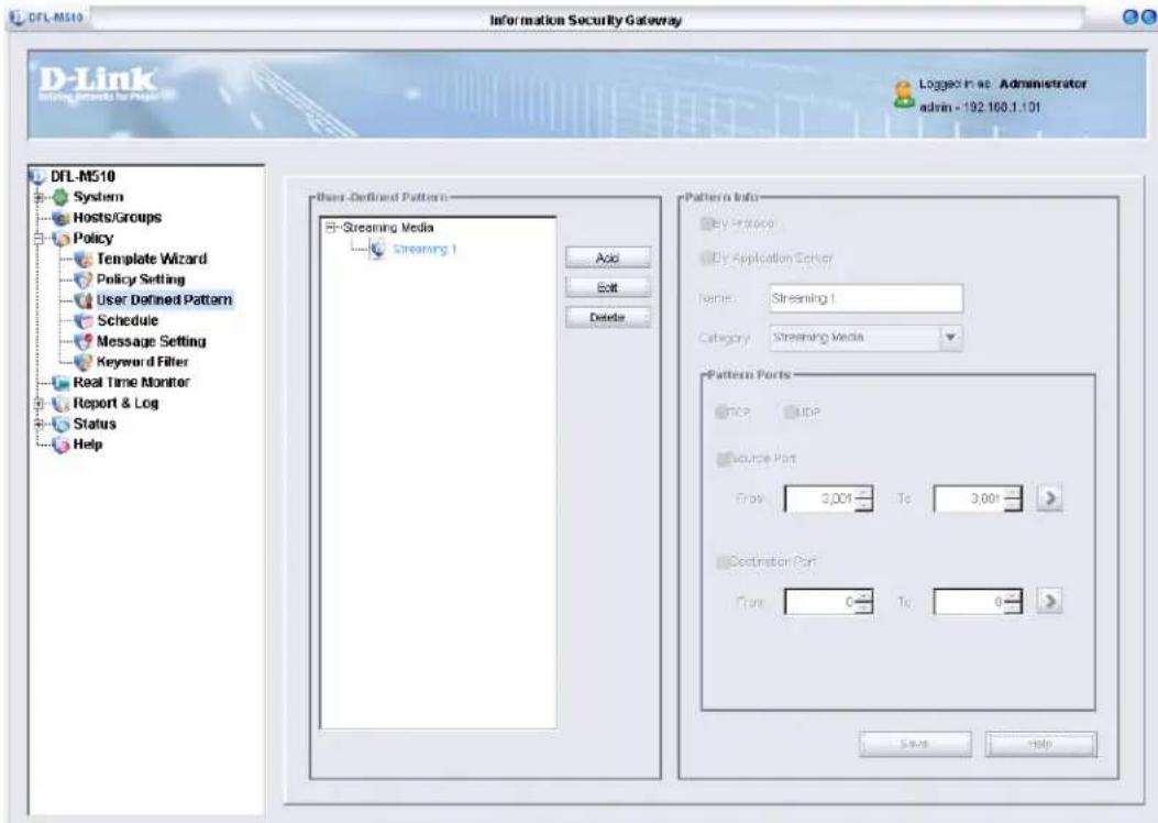
- Click Save.
DEFINING A PATTERN BY SERVER
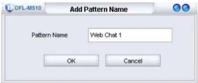
In this scenario, a web chat application is always connecting to a network server with the IP address 140.126.21.4. You can block this web chat application and then click the Save button to add a new rule as follows.
- In the User Defined Pattern screen, click Add.
-
Type in Web Chat 1 for the pattern name and click OK.
-
Input a rule name Web Chat 1, with category Web Control and servers, 140.126.21.4.
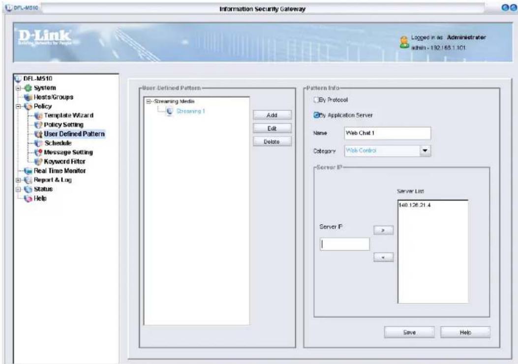
- Click Save.

The DFL-M510 supports 1500 sets of user-defined patterns by protocol and 1500 sets of user-defined patterns by Application Server.
The Schedule Screen
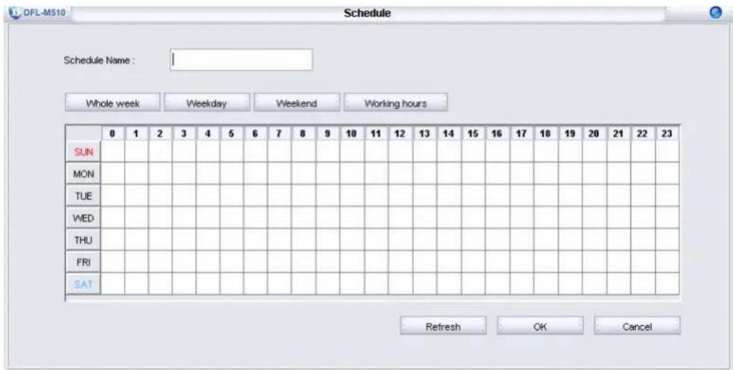
It is possible to define the active time range of a policy. The time range can be defined by the schedule. Each schedule has a name, and a time range. The time range is specified in units of hours.
Click Policy > Schedule to access the Schedule screen.
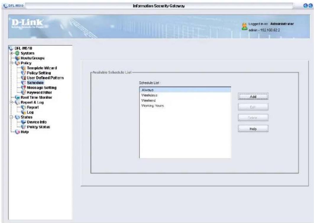
There are four predefined schedules. The Always schedule means the policy is always active. The Working Hours schedule means the policy is active during working hours. The regular working hours are Monday to Friday from 9:00 AM to 5:00 PM. The Weekdays schedule means the policy is active during the whole workdays. The regular workdays are Monday to Friday. The Weekend schedule means the policy is not active during the whole workdays. The regular Weekend days are Saturday to Sunday.
To Add or Modify a schedule press the Add or Modify button to open the schedule editing dialog box. Modify the schedule name and check the hour tab to include or exclude the hour represented by the tab.
Message Setting
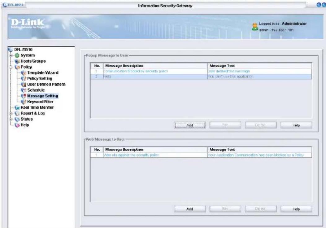
In this section, you can edit popup or Web messages. Refer to the following to add a popup message.
1. Click Policy > Message Setting.
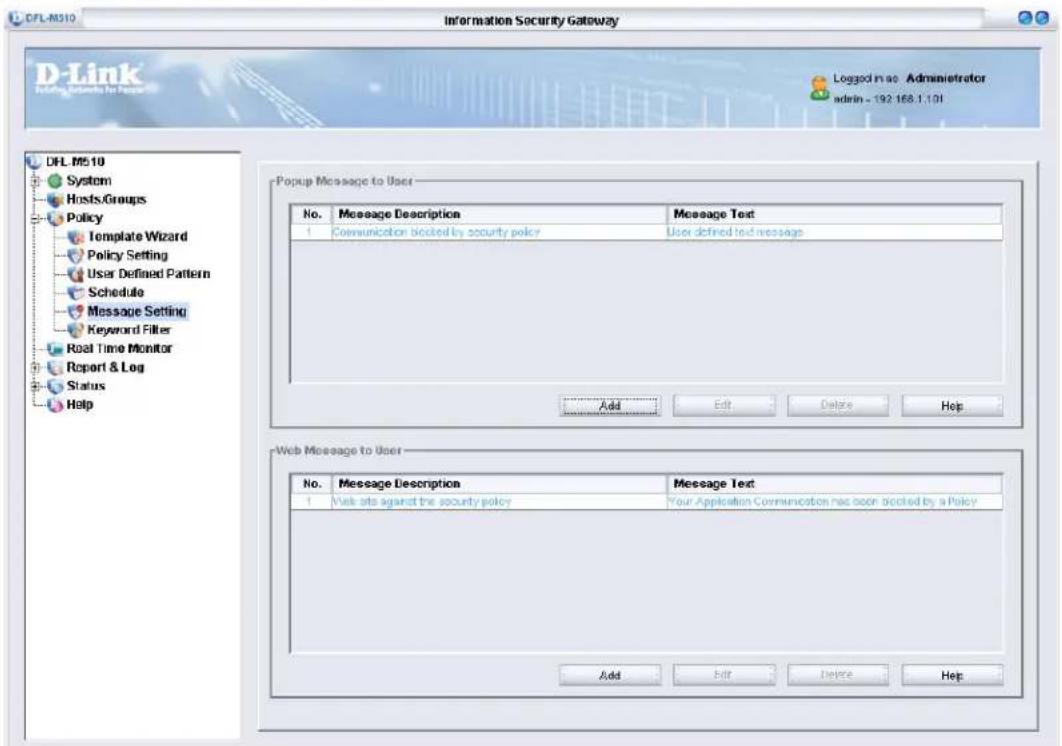
- Under Popup Message to User, click Add.
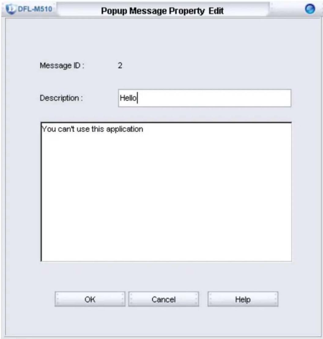
- Type a description and the content of the message and click OK.

When you turn off Messenger Service or enable Personal Firewall, the Win Popup Message function works correctly.
Keyword Filter
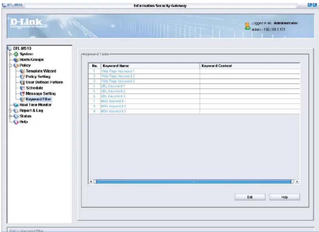
The DFL-M510 provides the following keyword functions:
- Web page keyword
- URL keyword
• MSN keyword
These keyword functions are used to describe applications of MSN and Web browsers.
Since all the keyword policies and other policies are too complex to display in a page, an integrated GUI frame is designed to aggregate these rules to use more easily. The special keyword policy GUI is illustrated as following.

This function only supports chapter by ASCII encoding.
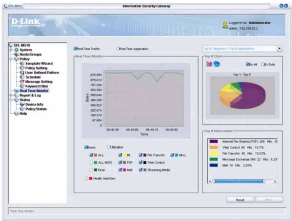
The Real Time Monitor provides real-time tracking of network usage in the form of text and graphs. System administrators can monitor significant application pattern events, quickly understand network status, and take imperative action.
The Real Time Monitor Screen
After you log on, click Real Time Monitor to open the following screen:
line
| Time | Bytes | | ---------- | ----- | | 08:42:45 | 678.06K | | 08:43:00 | 878.91K | | 08:43:15 | 781.25K | | 08:43:30 | 663.50K | | 08:43:45 | 585.94K | | 08:43:50 | 408.26K | | 08:43:15 | 390.62K | | 08:43:30 | 292.97K | | 08:43:45 | 195.31K | | 08:43:50 | 97.66K | | 08:43:15 | 97.66K | | 08:43:30 | 97.66K | Top N Categories / Top N Applications Top N Chart By Hit By Byte Top 1 - Top 5 Internet File Sharing (P2P) 209 Hbs 5% Web Control 66 Hbs 19.7% File Transfer 46 Hbs 13.03% Message Exchange (MI) 22 Hbs 6.29' Mail 10 Hbs 2.83% Reset Down Real Time Monitor | For Real-time Monitor to work properly, port 8801 - 8810 must be opened on the client PC to receive the analysis data from the DFL-M510. |
 | D-Link recommends not managing the DFL-M510 through a WAN link, since the Real-time Monitor feature would get data from the DFL-M510. |
The Real Time Monitor screen gives you access to the following:
• “Monitoring Real Time Traffic” on page 80
- “Monitoring Real Time Application” on page 81
MONITORING REAL TIME TRAFFIC
To monitor Real Time Traffic check the Real Time Traffic radio button.
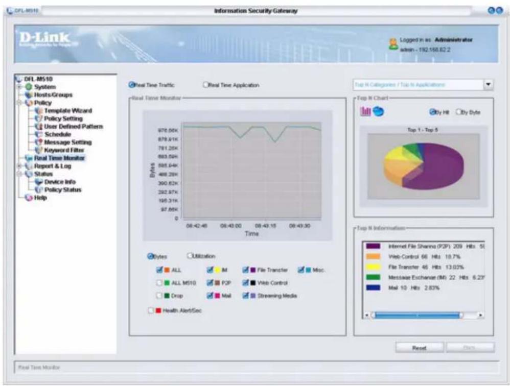
| ALL The number of | bytes of all packets received |
| ALL M510 The total | amount of traffic the DFL-M510 can manage |
| Drop | The number of bytes of packets that are identified as an application pattern and discarded by the DFL-M510 |
| IM | The number of bytes of all applications of the IM category |
| P2P | The number of bytes of all applications of the P2P category |
| The number of bytes of all applications of the Mail category | |
| File Transfer | The number of bytes of all applications of the File Transfer category |
| Web Control | The number of bytes of all applications of the Web Control category |
| Streaming Media | The number of bytes of all applications of the Streaming Media category |
| Misc. | The number of bytes of all traffic which does not belong to IM, P2P, Mail, File Transfer, or Streaming Media |
| Health Alert/Sec | The number of events that a packet was detected as a heath concern packet |
Administrators can accumulate and analyze detected application patterns by information revealed from their packets. These are explained in the Top N analysis section.
REFRESH TIME
The system provides the new traffic status every thirty seconds.
TRAFFIC LINES
One line in the traffic chart means one meter of current time. Each line can be hidden or shown by clicking the check box before the specified label.
SCOPE
Click the drop-down arrow to select a group or subnet to monitor. It filters hosts and doesn't affect the current traffic status but instead zooms into the subset of the hosts that are specific by each case.
MONITORING REAL TIME APPLICATION
To monitor Real Time Application check the Real Time Application radio button.
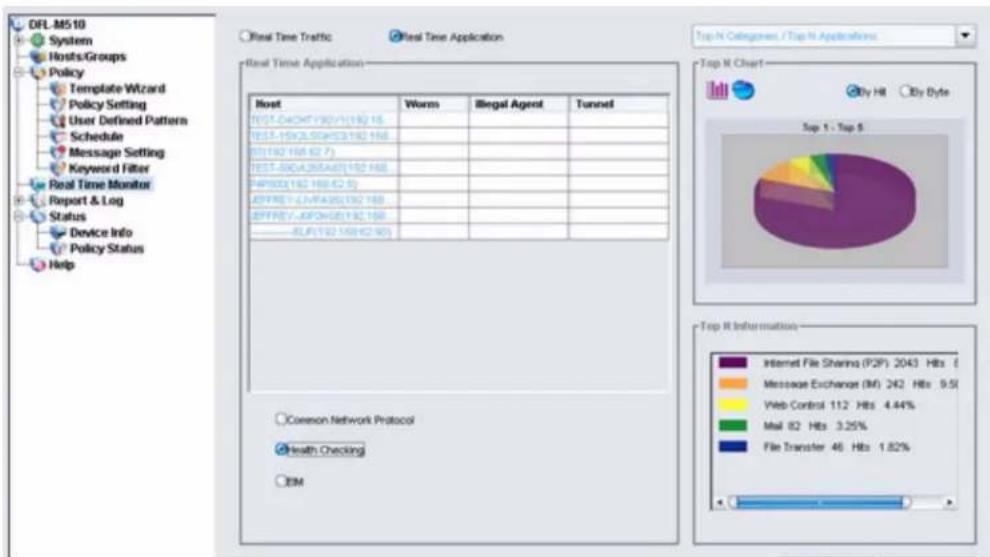
The Real Time Application page shows management information classified by pre-defined types and hosts.
The left of this screen displays the current application information; the right of this screen displays the accumulated application information for Top N analyzing. The right part is the same as the right part of real time traffic.
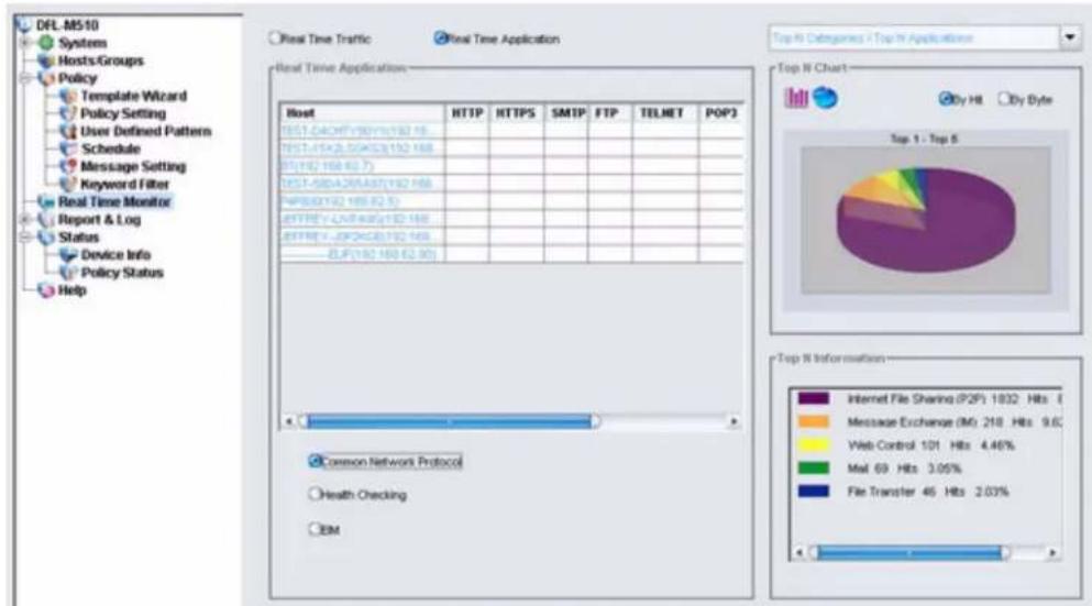
There are three tables: the common network protocol table; the EIM table; and the health checking table. Select the radio button to display each table. The EIM table is the default.
COMMON NETWORK PROTOCOL
The common network protocol table shows the current status of each host. This table is a layer 4 table and network applications are monitored at the network port number. The common network protocol contains HTTP, HTTPS, SMTP, FTP, TELNET, POP3, IRC, NNTP, and IMAP. If a host is connecting to the Internet via the above ports, the table shows a check mark to indicate the host is currently connecting.
pie
| Category | Value | |---|---| | Internet File Sharing (P2F) | 1832 | | Message Exchange (IM) | 218 | | Web Control | 101 | | Mail | 69 | | File Transfer | 45 | | Health Checking | |HEALTH CHECKING
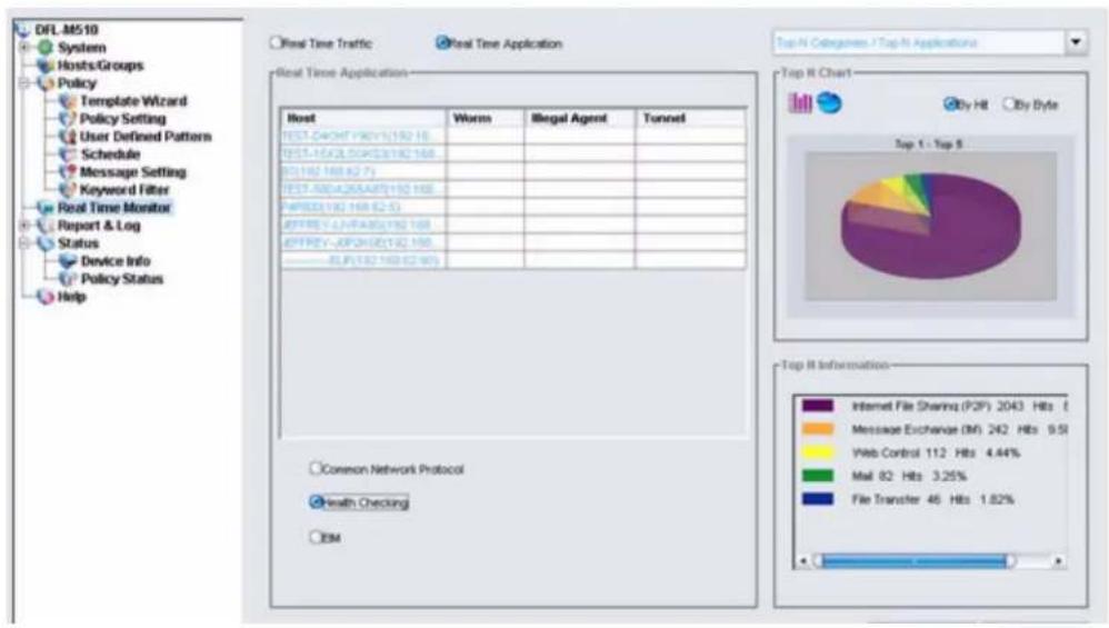
The Health Checking table is a layer seven table. Instead of classifying the application pattern, several packets that come from attacking tools can damage the host. Some of the packets are assembled and stored in the file system and are detectable by anti-virus software. Some packets try to get system authorized control and run as an operating system's administrator without storing to the file system. These packets are invisible to almost all anti-virus software, but detectable by the DFL-M510. When those packets come from a host and are detected, the corresponding field shows a check mark to indicate the host has health concern problems.
Health concern problems include network based worms, illegal agents, and tunnels. Network based worms do not include common viruses, since they are easy to discover by standard virus software.
Illegal agents include backdoors, trojans, spyware, and ad-ware.
Tunnels are host-based software. They provide a secure channel for communication. The purpose is to break through a firewall and escape content inspecting. For example, like soft ether, VNN, and VNC.
pie
| Category | Value | |---|---| | Web Control | 112 | | Mail | 82 | | File Transfer | 46 | | Message Exchange (IM) | 242 | | Email | 9.51 | | Web Control (IH) | 4.44% | | Mail (IH) | 3.25% | | File Transfer (IH) | 1.82% |EIM
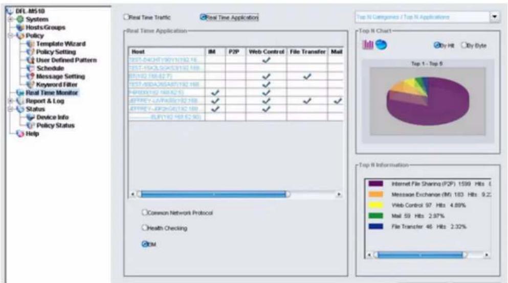
The EIM table provides layer seven monitoring. A packet is classified by its application pattern and summarized into six categories: IM, P2P, Web application, file transfer, E-mail, and media.
If a host is connecting to the Internet and identified as a category application, the table shows a check mark to indicate the host is currently running the application with that specific category.
TWO LEVELS TOP N ANALYSIS
Administrators can review detected application patterns by information revealed from its packets. All triggered incidents are categorized on the principle of sequence, health, time of occurrence, name of pattern, source address, destination address, counts, and responsive actions (dropping packets, disconnects, emailing the administrator in charge, or keeping logs of incidents,) and are all displayed in charts for administrators to quickly understand the present status of the network. These monitoring charts have two levels. First: choose one chart from the six charts; then pick one item from the first level to display the second level chart.
TOP N CATEGORIES/TOP N APPLICATION
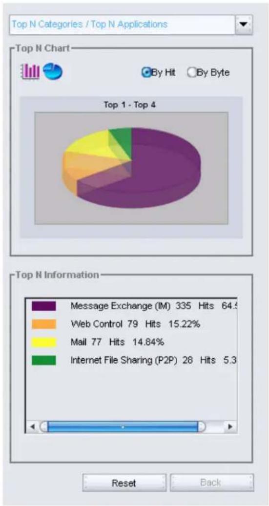
In these charts, the first level shows the top 7 categories. When a category is chosen, the second level shows the top 10 applications in the chosen category. The following means that the top category is the IM category. The following means that the top category is Message Exchange (IM).
pie
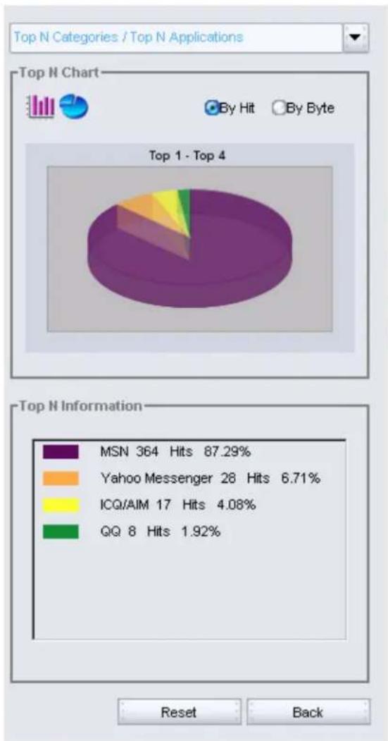
| Category | Hits | Percentage | | -------- | ---- | ---------- | | Message Exchange (IM) | 335 | 64.5% | | Web Control | 79 | 15.22% | | Mail | 77 | 14.84% | | Internet File Sharing (P2P) | 28 | 5.3% |The lower list shows details of each category. When the IM category is chosen, the second level chart covers the first chart as follows:
pie
| Category | Hits | Percentage (%) | | :--- | :--- | :--- | | MSN | 364 | 87.29 | | Yahoo Messenger | 28 | 6.71 | | ICQ/AIM | 17 | 4.08 | | QQ | 8 | 1.92 | Top N Information Reset BackIt would be understood that the MSN is the most frequent application within the IM category.

If you press Reset, all data is erased. Click Back to go to the previous page.
TOP N APPLICATIONS / TOP N USERS
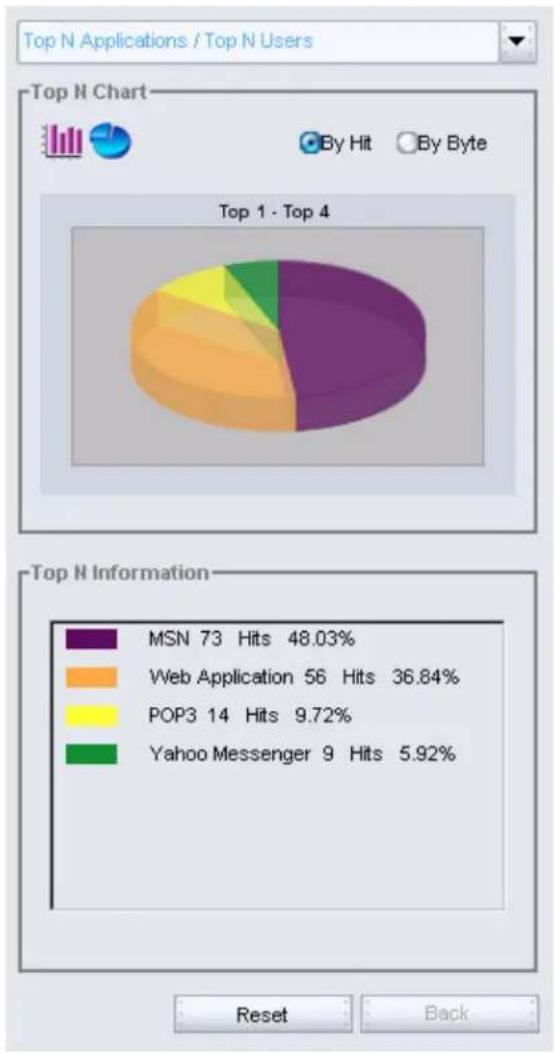
In these charts, the first level shows the top 10 applications. When an application is chosen, the second level shows the top 10 users in the chosen application.
The following means that the top application is MSN.
pie
| Rank | Count | Hits (%) | | ---- | ----- | -------- | | Top 1 - Top 4 | 48 | 48.03 | | Top 1 - Top 4 | 56 | 36.84 | | Top 1 - Top 4 | 14 | 9.72 | | Top 1 - Top 4 | 9 | 5.92 | The chart displays the distribution of hit counts and user types for the Top 1 to Top 4. The legend identifies four categories: MSN, Web Application, POP3, and Yahoo Messenger. The bottom panel shows the corresponding information.TOP N GROUPS/TOP N APPLICATIONS
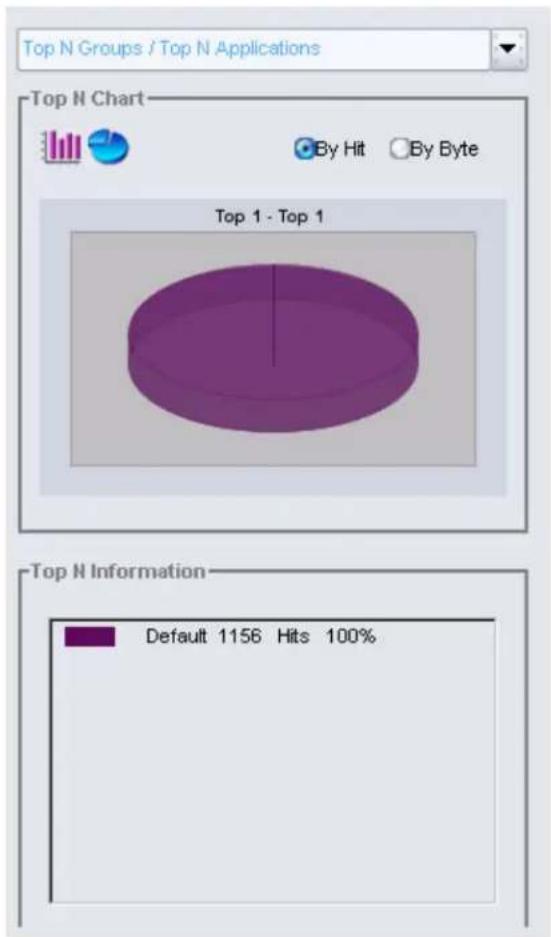
In these charts, the first level shows the top 10 groups. When a group is chosen, the second level shows the top 10 Applications. The following means that the top group is the default group.
pie
| Category | Count | | -------------- | ----- | | Top 1 - Top 1 | 1156 | | Bottom Left | 100% |TOP N USERS/TOP N APPLICATIONS
In these charts, the first level shows the top 10 users. When a user is chosen, the second level shows the top 10 applications in the chosen user. The following means that the top user is Terry.
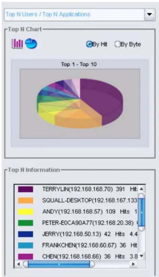
pie
| App Name | Hit Count | Bytes | | :--- | :--- | :--- | | TERRYLIN | 391 | 192.168.168.70 | | SQUALL-DESKTOP | 133 | 192.168.167.133 | | ANDY | 1 | 192.168.168.57 | | PETER-EOCA90A77 | 20.38 | 192.168.20 | | JERRY | 4.4 | 192.168.50.13 | | FRANKCHEN | 67 | 192.168.60.67 | | CHEN | 3.8 | 192.168.168.66 |TOP N HEALTH CONCERNS/TOP N USERS
In these charts, the first level shows the top 3 health concerns. When a health concern is chosen, the second level shows the top 10 users in the chosen health concern.
The following means that the top health concern is the illegal agent.
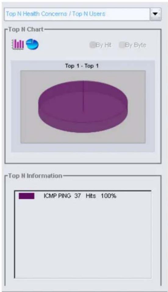
pie
| Category | Count | | -------- | ----- | | Top 1 - Top 1 | 1 | | ICMP PING | 37 | | Hits | 100% |TOP N USER WITH HEALTH CONCERNS/TOP N HEALTH CONCERNS
In these charts, the first level shows the top 10 users with health concerns. When a user is chosen, the second level shows the top 3 health concerns in the chosen user.
The following means that the top user with health concern is CJHO.
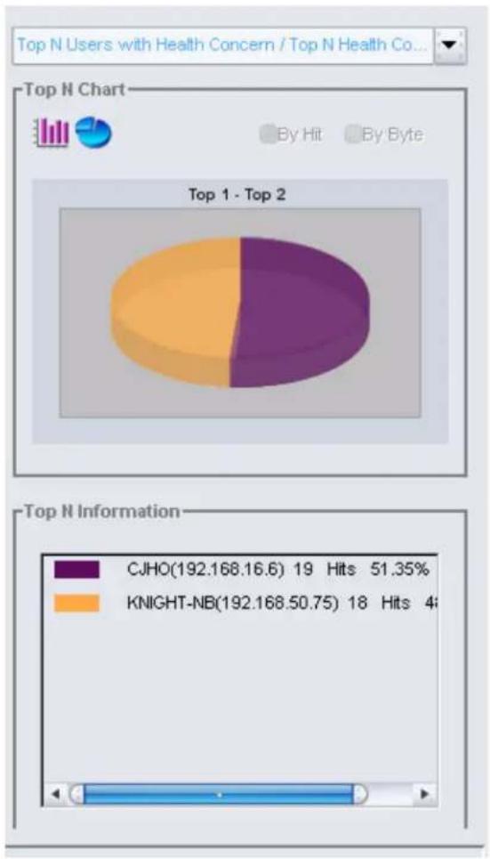
pie
| Rank | Segment | Hits | | ---- | ------- | ---- | | Top 1 - Top 2 | Purple | 51.35% | | Top 1 - Top 2 | Orange | 48.00% |The Report & Log screen allows administrators to view detailed reports and logs of the device status.
The Report & Log Screen
After you log on, click Report & Log to open the following screen:
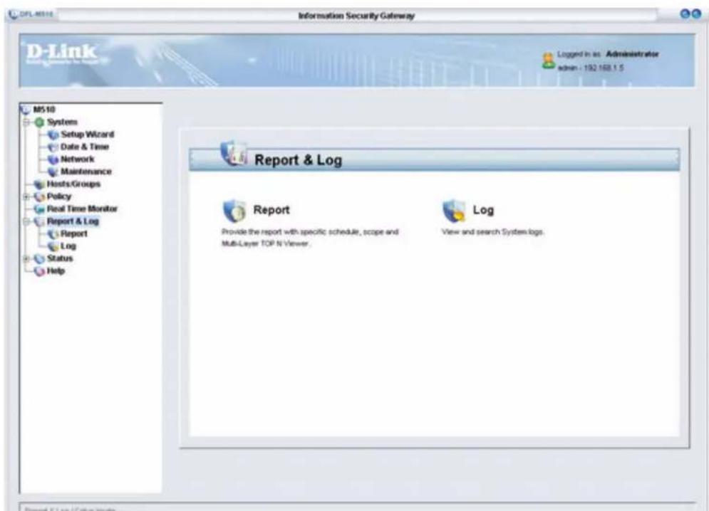
The Report & Log screen gives you access to the following tabs:
• “The Report Tab” on page 92
• “The Log Tab” on page 94
THE REPORT TAB
To view the Report tab, click Report & Log /Report.
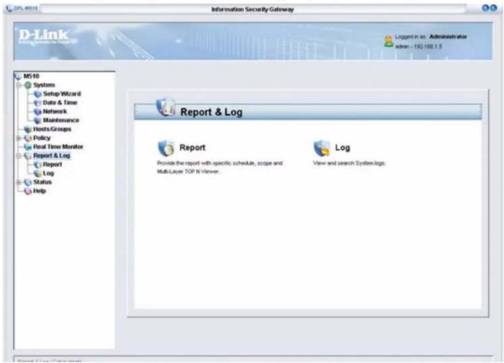
In the Report Title field, type a title for the report and click Generate.
INTERACTIVE REPORT
After you click Generate, the report window opens.
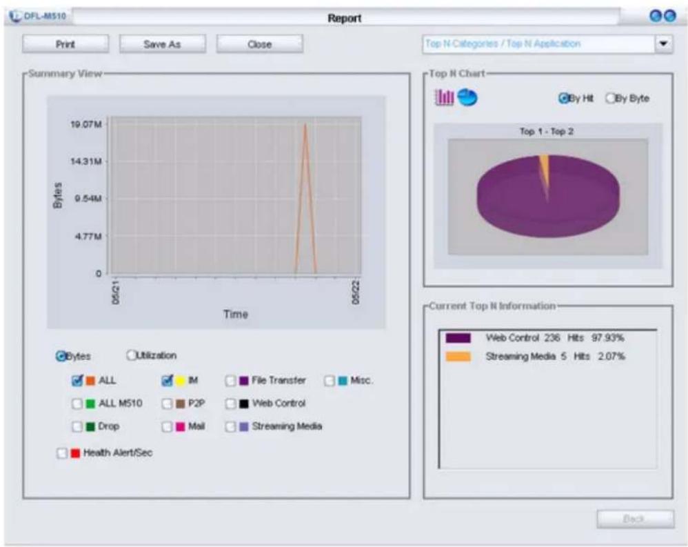
line
| Time | Bytes | |------|-----------| | 05/21 | 19.07M | | 05/22 | 4.77M |The above screen is described in the Real Time Monitor chapter. See “Monitoring Real Time Traffic” on page 80.
Click Print to print the report. Click Save As to save the report to the local computer. Click Close to close the report window.
VIEWING A SAVED REPORT
Reports are saved in HTML format and can be viewed in a Web browser.
1. Click Save As.
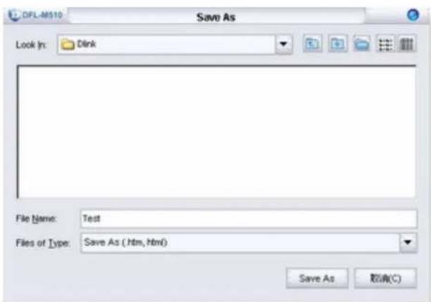
- Type a name for the report and click Save As.
- Open the file you saved in your Web browser.
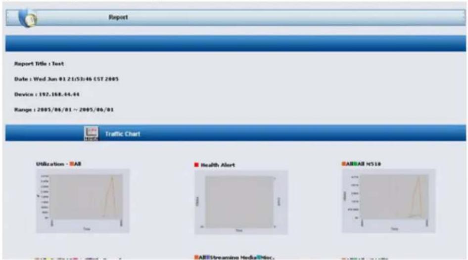
Scroll down to view the details of the report.
THE LOG TAB
To view the Log tab, click Report & Log/Log.
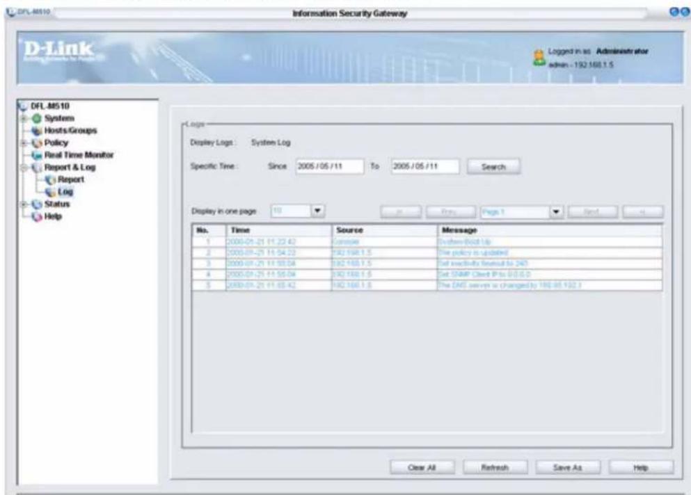
The log involves three lists of records. The system log records the device status changes and firmware operational conditions. It will statically list out incidents on the log windows when there are any. It is the administrator's decision to activate the log display by clicking Refresh. On the log
display list, the default setting of the system is to display all information regarding incidents, including the occurring, source, and message. Administrators can inspect data and filter out unnecessary events.
SEARCHING FOR LOGS BY A SPECIFIC TIME
To search a log for a specific time, specify the time under Specific Time and click Search.
SETTING THE LOG DISPLAY
The Display in one page field, lets you define how many log records display in one page. The default value is 10.
NAVIGATING LOGS
Use the navigation arrows </> to jump to the first or last page. Use Prev/Next, to go to the previous or next page. Go to a specific page by selecting it from the Page drop-down arrow.
The Status screen provides information on the current network and system settings. You can also find details of what applications can be monitored and incorporated into your policies.
The Status Screen
After you log on, click Status to open the following screen:
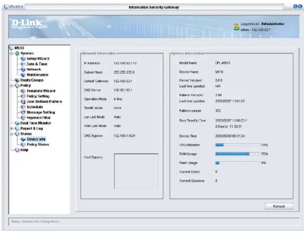
The Status screen gives you access to the following tabs:
• “The Device Info. Tab” on page 98
• “The Policy Status Tab” on page 100
THE DEVICE INFO. TAB
The Device Info. tab information is updated every minute. You can also click the Refresh button to update the information. To view the Device Info. tab, click Status/Device Info.
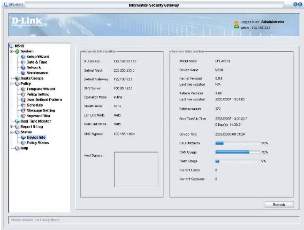
NETWORK INFORMATION
| IP Address Shows the IP Address (the default is 192.168.1.1) | |
| Subnet Mask Shows the subnet mask (the default is 255.255.255.0) | |
| Default Gateway Shows the default gateway (the default is 192.168.1.254 | |
| DNS Server Shows the DNS server address | |
| Operation Mode Shows the defense status of the device | |
| Stealth Mode Shows if stealth mode is enabled | |
| Lan Link Mode Shows the LAN link mode | |
| Wan Link Mode Shows the WAN link mode | |
| DMZ Bypass Shows the DMZ bypass; packets are not monitored in DMZ | |
| Host Bypass Shows the host bypass |
SYSTEM INFORMATION
| Model Name Shows the model name | |
| Device Name Shows the device name | |
| Kernal Version Shows the kernal version | |
| Last time updated Shows last time the firmware was updated | |
| Pattern Version Shows the pattern version | |
| Last time updated Shows the last time the pattern was updated | |
| Pattern number Shows the pattern number | |
| Boot Time/Up Time Shows the last time the device was booted up | |
| Device Time Shows the system device time | |
| CPU Utilization | Shows CPU utilization, monitor CPU usage to prevent overload |
| RAM Usage Shows RAM usage, monitor memory usage to prevent overload | |
| Flash Usage Shows flash usage, monitor flash usage to prevent overload | |
| Current Users Shows the total number of hosts, monitor the host table to prevent it from running out | |
| Current Sessions Shows the total number of sessions, monitor the sessions table to prevent connection sessions from running out | |

CPU utilization, RAM and Flash Usage display the percentage being used, expressed as an integer percentage and calculated as a simple by time interval.
THE POLICY STATUS TAB
To view the Policy Status tab, click Status/Policy Status.
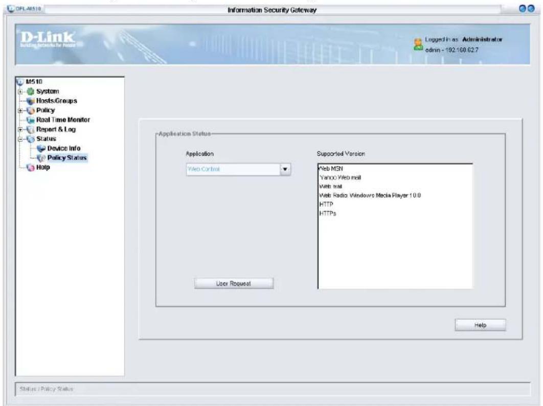
APPLICATION STATUS
Click Application to select the application category which you want to know. It will display the current version in the right field. The following are the currently supported applications and version of the DFL-M510.
| Application Support Version | |
| Web Control Web MSN | |
| Yahoo Web mail | |
| Web Radio: Windows Media Player 10.0 | |
| HTTP | |
| HTTPS | |
| Internet File Sharing (P2P) B | Bittorrent 4.0.1 |
| ezPeer 1.9 | |
| Overnet: eDonkey 2000-1.1.2 | |
| MLdonkey2.5 | |
| Shareaza V2.1.0.0 | |
| Morpheus 4.6.1 | |
| Bearshare 4.6.3.1 | |
| Kuro 6.0 | |
| KaZaa 3.0 | |
| Gnutrlla | |
| Grokster v2.6 | |
| DirectConnect 2.2.0 | |
| Beedo 2.0 | |
| PP365 2004 | |
| Streaming Media RealPlayer | 10.5 |
| Stream ASF Download: Windows Media Player 10.0 | |
| Stream WMV Download: Windows Media Player 10.0 | |
| H.323 | |
| RTSP | |
| iTunes 4.7 | |
| WinAmp 2.80 | |
| Player365 | |
| File Transfer General FTP App | Application |
| GetRight 5.01 | |
| Message Exchange (IM) MSN | 7.X |
| AIM 5.5 | |
| QQ 2004 | |
| ICQ4, ICQ 2003b | |
| Yahoo Messenger 6.0 | |
| Odigo v4.0 Beta (Build 689) | |
| TM2.5 Build0728 | |
| MIRC 6.16 | |
| Rediff BOL 7.0 Beta | |
| Mail SMTP | |
| POP3 | |
| IMAP4 |

The DFL-M510 manages P2P downloads by using the P2P Protocol. In this architecture, no what version of the client you use, the DFL-M510 can manage it.
REQUEST NEW APPLICATION SUPPORT
If there is a new application that the DFL-M510 can not support, you can use this function to request support.
- Click User Request. The following screen appears.
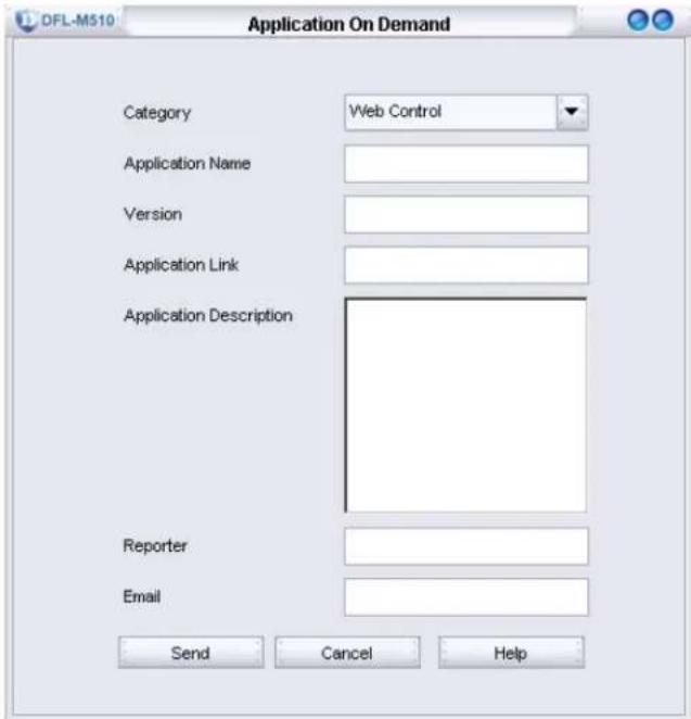
- Complete all information of the new application, and click Send. You will be contacted by the D-Link support team.
This section covers the following topics:
- “Terminal/SSH (Secure Shell) Connection” on page 105
- “CLI Command List” on page 106
- “Help Command” on page 106
- “Get Command” on page 107
- “Set Command” on page 108
- “Exit Command” on page 115
- “Reboot Command” on page 116
- “Reset Command” on page 116
• “Ping Command” on page 116
Terminal/SSH (Secure Shell) Connection
The DFL-M510 Console Service provides administrators a text-mode interface to configure the DFL-M510 and its arguments via an RS-232 serial cable. The DFL-M510 devices provides terminal emulation and SSH connection service. Administrators can attach an RS-232 cable to the RS-232 console port on the DFL-M510, and log in with the super terminal program provided by Windows 95/98/2000/NT/XP; or use the remote login command line interface by using terminal connection software with SSHv2 encryption function.
These two methods of accessing the command line interface have three major differences between them:
- SSH service provides administrators an ISG remote control mechanism and higher security compared to a traditional Telnet connection.
- Since remote access is considered more risky than accessing from a terminal connection, some functions are limited to the terminal connection service only. For example, the device booting message does not show on the remote access. (Details of the limited functions are provided in the next section.)
- For the sake of security, the SSH service provided by ISG devices can be shut down. From security stand point, the best way to protect against brute force approach is to prolong the interval between login attempts. Therefore, the SSH login attempt is limited to 3 times, and each interval 60 seconds. If a user has failed logins that exceeds this or is stuck in the login process for more than 60 seconds, the SSH connection will be terminated, and login resources are released.
In addition, the DFL-M510 only allows one SSH connection at a time for the consideration of the conformity of system configuration and the security of the remote connection.
Getting Started
Once you have accessed the Command Line Interface (CLI) with a terminal connection, press any key and the following prompt will appear. Enter the user name and password: the default user name is admin, the default password is admin.
Welcome to D-Link DFL-M510 Console Environment
Copyright (C) 2005 D-Link Corp.
DFL-M510 login:
CLI Command List
You can use the console or SSH to connect the DFL-M510. After login, you can use the CLI commands to configure the DFL-M510. The complete CLI commands are described as follows.
| Commands Description | |
| help Getting information of all command's usage and argument configuration | |
| get Display all kinds of configuration information of the DFL-M510the DFL-M510 | |
| set Set the system | parameter |
| history Display all commands which you have used | |
| exit Exit command | shell |
| reboot Reboot system | |
| reset Reset system configuration to default settings, type “y” to load default setting. | |
| ping Send ICMP echo request messages | |
Help Command
Help is used for getting information of other command's usage and argument configuration.
| Main command | Sub command Example Command description | ||
| help | get | help get | Display all information of “get” command. |
| set | help set | Display all information of “set” command. | |
| history | help history | Display all information of “help” command | |
| exit | help exit | Display all information of “exit” command | |
| reboot | help reboot | Display all information of “reboot” command | |
| reset | help reset | Display all information of “reset” command | |
| ping | help ping | Display all information of “ping” command | |
EXAMPLE
(A) help get
help get
get - Get system parameters. Available commands
system - System configurations, including IP, password and etc.
time - Device clock setting
state - Device operation state
interface - Device interface configuration
(B) help set
>> help set
set - Set system parameters. Available commands
    system - System configurations, including IP, password and etc.
    time - Device clock setting
    state - Device operation state
    remote - Setup remote access configuration.
    Interface - Change interface link mode
(C) help history
>> help history
history - Show all command history
(D) help exit
>> help exit
exit - Log out
(E) help reboot
>> help reboot
reboot - Reboot system
(F) help reset
>> help reset
reset - Reset system configurations to manufacturing defaults
(G) help set
>> help ping
ping - Ping utility
Get Command
This command will display all kinds of configuration information of the DFL-M510.
| Main command | Sub command | Example Command | description |
| get system get system Display system configurations, including IP, password and etc. | |||
EXAMPLE
(A) get system
>> get system
Device name: M510
MAC Address: 00:00:00:00:00:00
DFL-M510 IP Address:192.168. 80.244, netmask:255.255. 0. 0,
gateway:192.168.168.253
TCP cold start duration time: 300 seconds
VLAN function: off. VLAN ID: 1.
Detection parameters:
Maximum ping packet size: 1024.
TCP state check bypass: off.
WAN port: policy check <off> Stealth < on> max ping 10000.
LAN port: policy check <off> Stealth < on> max ping 10000.
Remote access:
HTTP:
Access: all
1 - Client IP: all    Netmask: 255.255. 0. 0
2 - Client IP: 0. 0. 0. 0 Netmask: 255.255.255. 0
3 - Client IP: 0. 0. 0. 0 Netmask: 255.255.255. 0
SSH:
Access: all
1 - Client IP: all    Netmask: 255.255.255. 0
2 - Client IP: 0. 0. 0. 0 Netmask: 255.255.255. 0
3 - Client IP: 0. 0. 0. 0 Netmask: 255.255.255. 0
>> _
(B) get time
get time
Current time : (GMT + 0) Mon Apr 18 08:34:37 2005
DST time : (GMT + 0) Mon Apr 18 08:34:37 2005
System duration: 0 days 0:43:10
(C) get state
get state
Operation mode: In-Line
(D) get interface
get interface
Interface:
WAN: auto.
LAN: auto.
Set Command
Use this command to set the system's parameter.
| Main command | Sub command | Command description |
| set system Set | system configurations, including IP, password and etc. | |
| time Set device clock | ||
| state Set device operation mode | ||
| remote Set remote control mode | ||
| interface Set interface link mode | ||
"SET SYSTEM" COMMAND
| Prefix | 2^nd command | Example Command description | |
| set system ip | set system ip | 192.168.80.244 Set device's IP | |
| mask set sys | system mask 255.255.0.0 Set device's mask | ||
| gateway set | system gateway | Set device's default gateway | |
| 192.168.80.244 | |||
| passwd set | system passwd Set administrator's | new password | |
| detect set | system detect Set the relating argum | ents for ISG'soutgoing and incoming packetsdetection. | |
| vlan set sys | tem vlan Set the VLAN environm | nt relatedparameters | |
| name set | system name | Set device's name | |
| Prefix command | 2^nd command | 3^rd command | Postfix command | Example | Command description |
| set system detect | tcptimeout | 20 - 2592000 | set system detect tcptimeout 6000 | Set TCP connection timeout | |
| policy | wan | on/ | set system detect policy wan on | Turn on wan port's policy check | |
| off | set system detect policy wan off | Turn off wan port's policy check | |||
| lan | on | set system detect policy lan on | Turn on lan port's policy check | ||
| off | set system detect policy lan off | Turn off lan port's policy check | |||
| pingmax wan | 10 - 300000 set | system detect ping wan 5000 | Set max ICMP count of wan port | ||
| lan | 10 - 300000 | set system detect ping lan 5000 | Set max ICMP count of lan port | ||
| stateful | on | set system detect stateful on | Turn on TCP state bypass | ||
| off | set system detect stateful off | Turn off TCP state bypass | |||
| pinglen | 64 - 1500 | set system detect pinglen 1024 | Set max acceptable ICMP size 64 - 1500 | ||
| tcpcoldstart | 0 - 300 | set system detect tcpcoldstart 250 | Set TCP cold start timer | ||
| Prefix | 2^nd command | 3^rd command | Example | Command description |
| set system vlan | on | set system vlan on | Turn on VLAN function | |
| off | set system vlan off | Turn off VLAN function | ||
| vid | 1 - 4094 | set system vlan 1 | Set VLAN ID |
EXAMPLE
(A) set system ip
set system ip 192.168.1..245
Do you want to apply this setting immediately?
Your current ssh/http connection will be cut off. (y/n)
(B) set system mask
set system mask 255.255.255.0
Do you want to apply this setting immediately?
Your current ssh/http connection will be cut off. (y/n)
(C) set system gateway
set system gateway 255.255.255.0
Do you want to apply this setting immediately?
Your current ssh/http connection will be cut off. (y/n)
(D) set system passwd
set system passwd
Original password: *****
New password: *****
Retype password: *****
(E) set system detect tcptimeout
set system detect tcptimeout 100000
Change TCP session time out limit OK.
(F) set system detect policy wan on
set system detect policy wan on
Apply policy check for wan interface OK.
(G) set system detect policy wan off
set system detect policy wan off
Remove policy check for wan interface OK.
(H) set system detect policy lan on
set system detect policy lan on
Apply policy check for lan interface OK.
(I) set system detect pingmax wan 100000
set system detect pingmax wan 100000
Change wan port maximum ping packet limit OK.
(J) set system detect pingmax lan 100000
set system detect pingmax wan 100000
Change lan port maximum ping packet limit OK
(K) set system detect stateful on
set system detect stateful on
Turn on TCP state check bypass
(L) set system detect stateful off
set system detect stateful off
Turn off TCP state check bypass
(M) set system detect pinglen 1024
set system detect pinglen 1024 Change maximum length of ping packet OK.
(N) set system detect tcpcoldstart 250
set system detect tcpcoldstart 250 Change TCP cold start duration time OK.
(O) set system vlan on
set system vlan on Turn on VLAN function.
(P) set system vlan off
set system vlan off Turn off VLAN function.
(Q) set system vlan vid 1
set system vlan vid 1 Set VLAN ID OK
(R) set system name
set system name Press new device name: M510
"SET TIME" COMMAND
| Main command Sub command Example Command description | ||
| set time set time Set device clock | ||
EXAMPLE
(A) set time
set time Current time : (GMT + 0) Mon Apr 18 10:57:15 2005 Specify year [2000 - 2099] : Specify month [1 - 12] : Specify date [1 - 31] : Specify hour [0 - 23] : Specify minute [0 - 59] : Specify second [0 - 59] : Specify timezone [-12 to +12] : Change time successfully !
Current time : (GMT + 0) Mon Apr 18 10:57:43 2005 DST time : (GMT + 0) Mon Apr 18 10:57:43 2005 System duration: 0 days 1:9:1
"SET STATE" COMMAND
| Prefix | 2^nd command | Example Command | description |
| set state inline | Set state inline | Set ISG to execute normally based on its configured policy | |
| Monitor Set state | monitor ISG only inspects and keep logs does not drop packets or disconnects on its own accord | ||
| Bypass Set state | bypass ISG will transmit all received packets to work on another port unconditionally, which can be regarded as bridge mode. | ||
| Span Set state | span ISG accept packets mirrored from hub or switch mirror port and is able to reset network connection; two connection ports of ISG work separately at this time. |
EXAMPLE
(A) set state inline
set state inline
Set system state to In-Line mode.
(B) set state monitor
set state monitor
Set system state to MONITOR mode.
(C) set state bypass
set state bypass
Set system state to BYPASS mode.
(D) set state span
set state span
Set system state to SPAN mode.
"SET REMOTE" COMMAND
| Prefix command | 2^nd command | 3^rd command | Postfix command | Command description |
| set remote http | access wan | Enable remote access using browser from | ||
| lan Enable remote access using | wan port | |||
| all Enable remote access using | g browser from lan port | |||
| disable Disable remote access using | browser from wan and lan port | |||
| ip 1 xxx.xxx.xxx.Assign specify IP can use | browser to remote access device | |||
| mask 1 xxx.xxx.xxx.xxx Assign specify subnet mask can use | ||||
| Prefix command | 2^nd command | 3^rd command | Postfix command | Command description |
| set remote ssh | access wan | Enable remote access using SSH from wan port | ||
| lan Enable remote access using SSH from lan port | ||||
| all Enable remote access using SSH from wan and lan port | ||||
| disable Disable remote access using SSH | ||||
| ip 1 xxx.xxx.xxx.Assign specify IP can use SSH to remote access device | ||||
| mask 1 xxx.xxx.xxx.Assign specify subnet mask can use SSH to remote access device | ||||
EXAMPLE
(A) set remote http access wan
set remote http access wan
Do you want to apply this setting immediately?
Your current ssh/http connection will be cut off. (y/n)
(B) set remote http access lan
set remote http access lan
Do you want to apply this setting immediately?
Your current ssh/http connection will be cut off. (y/n)
(C) set remote http access all
set remote http access all
Do you want to apply this setting immediately?
Your current ssh/http connection will be cut off. (y/n)
(D) set remote http access disable
set remote http access disable
Do you want to apply this setting immediately?
Your current ssh/http connection will be cut off. (y/n)
(E) set remote http ip 1 192.168.1.230
set remote http ip 1 192.168.1.230
Do you want to apply this setting immediately?
Your current ssh/http connection will be cut off. (y/n)
(F) set remote http mask 1 255.255.255.0
set remote http mask 1 255.255.255.0
Do you want to apply this setting immediately?
Your current ssh/http connection will be cut off. (y/n)
(G) set remote ssh access wan
set remote ssh access wan
Do you want to apply this setting immediately?
Your current ssh/http connection will be cut off. (y/n)
(H) set remote ssh access lan
set remote ssh access lan
Do you want to apply this setting immediately?
Your current ssh/http connection will be cut off. (y/n)
(I) set remote ssh access all
set remote ssh access all
Do you want to apply this setting immediately?
Your current ssh/http connection will be cut off. (y/n)
(J) set remote ssh access disable
set remote ssh access disable
Do you want to apply this setting immediately?
Your current ssh/http connection will be cut off. (y/n)
(K) set remote ssh ip 1 192.168.1.230
set remote ssh ip 1 192.168.1.230
Do you want to apply this setting immediately?
Your current ssh/http connection will be cut off. (y/n)
(L) set remote ssh mask 1 255.255.255.0
set remote ssh mask 1 255.255.255.0
Do you want to apply this setting immediately?
Your current ssh/http connection will be cut off. (y/n)
"SET INTERFACE" COMMAND
| Main command | Sub command | Command description |
| set interface | Set interface link mode | |
EXAMPLE
(A) set interface
set interface
Interface.
WAN: auto
LAN: auto
Setup WAN port configuration :
Specify auto mode or speed [auto / 10 / 100] :
Specify stealth mode [on / off] :
Setup LAN port configuration :
Specify auto mode or speed [auto / 10 / 100] :
Specify stealth mode [on / off] :
Do you want to apply this setting immediately?
Your current ssh/http connection will be cut off. (y/n)
History Command
This command will display all commands which you have used.
| Main command | Sub command | Example Command | and description |
| history none | history Display all commands which you have used | ||
EXAMPLE
(A) history
history
1 : get system
2 : history
Exit Command
Use this command to exit command shell.
| Main command | Sub command | Example Command | and description |
| exit none exit | Exit command shell | ||
EXAMPLE
(A) exit
exit
Logout
Welcome to D-Link DFL-M510 Console Environment
Copyright (C) 2005 D-Link Corp.
DFL-M510 login:
Reboot Command
Use this command to reboot system.
| Main command | Sub command | Example Command | and description |
| reboot none | reboot Reboot system, type "y" to reboot the system. | ||
EXAMPLE
(A) exit
reboot
Are you sure to reboot system? (y/n)
Reset Command
Use this command to reset system configuration to default settings.
| Main command | Sub command | Example Command | and description |
| reset none reset | set Reset system | configuration to | default settings, type "y"totype "y" to load default setting. |
EXAMPLE
(A) reset
reset
This will set the system configuration to the default values, and then reboot the system.
Continue? (y/n)
Ping Command
Use this command to reset system configuration to default settings.
| Main command | Sub command Example Command description | |
| Ping xxx.xxx.xxx.xxx Ping 168.95.192.1 Send ICMP echo request messages | ||
EXAMPLE
(A) ping
ping 192.168.80.243
PING 192.168.80.243 (168.95.192.1): 56 data bytes
--- 168.95.192.1 ping statistics ---
1 packets transmitted, 1 packets received, 0% packet loss
Round-trip min/avg/max = 2.2/2.2/2.2 ms
Bandwidth
The transmission capacity of a given device or network
Bit
A Binary Digit (either a one or a zero); a single digit number in base-2. A bit is the smallest unit of computerized data.
Bridge
A device that connects two different kinds of local networks, such as a wireless network to a wired Ethernet.
Browser
A browser is an application program that provide a way to look at and interact with all the information on the World Wide Web
CLI (Command Line Interface)
In this interface, you can use line commands to configure the device or perform advanced device diagnostics and troubleshooting.
Console
This is a device (usually a computer) that you use to manage a networking device via a serial port (RS232) connection.
Crossover Cable
A cable that wires a pin to its opposite pin, for example, RX+ is wired to TX+. This cable connects two similar devices, for example, two data terminal equipment (DTE) or data communications equipment (DCE) devices.
DNS (Domain Name System)
Domain Name System links names to IP addresses. When you access Web sites on the Internet you can type the IP address of the site or the DNS name.
Domain Name
The unique name that identifies an Internet site. Domain Names always have two or more parts that are separated by dots. The part on the left is the most specific and the part on the right is the most general.
Ethernet
A very common method of networking computers in a LAN. There are a number of adaptations to the IEEE 802.3 Ethernet standard, including adaptations with data rates of 10 Mbits/sec and 100 Mbits/sec over coaxial cable, twisted-pair cable and fiber-optic cable. The latest version of Ethernet, Gigabit Ethernet, has a data rate of 1 Gbit/sec.
Events
These are network activities. Some activities are direct attacks on your system, while others might be depending on the circumstances. Therefore, any activity, regardless of severity is called an event. An event may or may not be a direct attack on your system.
FCC (Federal Communications Commission)
The FCC (Federal Communications Commission) is in charge of allocating the electromagnetic spectrum and thus the bandwidth of various communication systems.
Firewall
A hardware or software "wall" that restricts access in and out of a network. Firewalls are most often used to separate an internal LAN or WAN from the Internet.
Flash memory
A nonvolatile storage device that can be electrically erased and reprogrammed so that data can be stored, booted and rewritten as necessary.
FTP (File Transfer Protocol)
File Transfer Protocol is an Internet file transfer service that operates on the Internet and over TCP/IP networks. A system running the FTP server accepts commands from a system running an FTP client. The service allows users to send commands to the server for uploading and downloading files.
Gateway
A gateway is a computer system or other device that acts as a translator between two systems that do not use the same communication protocols, data formatting structures, languages and/or architecture.
HTTP (Hyper Text Transfer Protocol)
The most common protocol used on the Internet. HTTP is the primary protocol used for web sites and web browsers. It is also prone to certain kinds of attacks.
HTTPS (HyperText Transfer Protocol over Secure Socket Layer)
HyperText Transfer Protocol over Secure Socket Layer, or HTTP over SSL is a web protocol that encrypts and decrypts web pages. Secure Socket Layer (SSL) is an application-level protocol that enables secure transactions of data by ensuring confidentiality (an unauthorized party cannot read the transferred data), authentication (one party can identify the other party) and data integrity (you know if data has been changed).
ICMP (Internet Control Message Protocol)
A message control and error-reporting protocol between a host server and a gateway to the Internet ICMP uses Internet Protocol (IP) datagram, but the messages are processed by the TCP/IP software and are not directly apparent to the application user.
IM (Instant Messaging)
IM (Instant Messaging) refers to chat applications. Chat is real-time, text-based communication between two or more users via networked-connected devices.
IP (Internet Protocol)
(Currently IP version 4 or IPv4) The underlying protocol for routing packets on the Internet and other TCP/IP-based networks.
IRC (Internet Relay Chat)
It is a way for multiple users on a system to "chat" over the network.
ISP (Internet Service Providers)
Provide connections into the Internet for home users and businesses. There are local, regional, national, and global ISPs. You can think of local ISPs as the gatekeepers into the Internet.
LAN (Local Area Network)
A shared communication system to which many computers are attached. A LAN, as its name implies, is limited to a local area. LANs have different topologies, the most common being the linear bus and the star configuration.
Logs
Logs are device information that a device is scheduled to send out.
NAT (Network Address Translation)
The translation of an Internet Protocol address used within one network to a different IP address known within another network.
Network
Any time you connect two or more computers together, allowing them to share resources, you have a computer network. Connect two or more networks together and you have an internet.
NIC (Network Interface Card)
A board that provides network communication capabilities to and from a computer system. Also called an adapter.
P2P (Peer-To-Peer)
Peer-to-peer (P2P) is where computing devices link directly to each other and can directly initiate communication with each other; they do not need an intermediary. A device can be both the client and the server.
Packet Filter
A filter that scans packets and decides whether to let them through or not.
Port
An Internet port refers to a number that is part of a URL, appearing after a colon (:), directly following the domain name. Every service on an Internet server listens on a particular port number on that server. Most services have standard port numbers, for example, Web servers normally listen on port 80.
Protocol
A “language” for communicating on a network. Protocols are sets of standards or rules used to define, format and transmit data across a network. There are many different protocols used on networks. For example, most web pages are transmitted using the HTTP protocol.
Router
A device that connects two networks together. Routers monitor, direct and filter information that passes between these networks.
RS-232
RS-232 is an EIA standard which is the most common way of linking data devices together.
Server
A computer, or a software package, that provides a specific kind of service to client software running on other computers.
SSL (Secured Socket Layer)
Technology that allows you to send information that only the server can read. SSL allows servers and browsers to encrypt data as they communicate with each other. This makes it very difficult for third parties to understand the communications.
Subnet Mask
The subnet mask specifies the network number portion of an IP address. Your device will compute the subnet mask automatically based on the IP Address that you entered. You do not need to change the computer subnet mask unless you are instructed to do so.
Switch
A layer-2 network device that selects a path or circuit to send a data packet through.
TCP (Transmission Control Protocol)
TCP is a connection-oriented transport service that ensures the reliability of message delivery. It verifies that messages and data were received.
Telnet
Telnet is the login and terminal emulation protocol common on the Internet and in UNIX environments. It operates over TCP/IP networks. Its primary function is to allow users to log into remote host systems.
Terminal
A device that allows you to send commands to a computer somewhere else. At a minimum, this usually means a keyboard, display screen and some simple circuitry.
TFTP (Trivial File Transfer Protocol)
TFTP is an Internet file transfer protocol similar to FTP (File Transfer Protocol), but it is scaled back in functionality so that it requires fewer resources to run. TFTP uses the UDP (User Datagram Protocol) rather than TCP (Transmission Control Protocol).
Transparent Firewall
A transparent firewall, also known as a bridge firewall, is a device that can act as a bridge and also filter/inspect packets. You do not have to change other network settings when you add a transparent firewall to the network.
URL (Uniform Resource Locator)
URL is an object on the Internet or an intranet that resides on a host system. Objects include directories and an assortment of file types, including text files, graphics, video and audio. A URL is the address of an object that is normally typed in the Address field of a Web browser. A URL is basically a pointer to the location of an object.
WAN (Wide Area Networks)
WANs link geographically dispersed offices in other cities or around the globe including switched and permanent telephone circuits, terrestrial radio systems and satellite systems.
Hardware Specification
| CPU D-Link SOC DL-5100 | |
| System memory 128M SDR | RAM on board, 16M Flash on board |
| Ethernet 2 x 10/100 M auto | -sensing auto-crossing with frog light |
| Other port RS232(9 pin) | |
| LCD Module Blue background | und with white light LCD Panel |
| Power AC LINE 100-240V | AC 50-60Hz 0.8A MAX |
| Dimension (L*D*H, mm) 44 | 0mm * 250mm * 44mm |
Features Specification
Application Detection / Prevention / Management
| Application Class | Application Type | Application Name/ | Control Points |
| 1.Message Exchange | *Instant Messengers (IM) | 1. MSN2. Yahoo Messenger3. ICQ/AIM4. QQ5. IChat (MAC)7. Odigo8. Trillian.... | 1. Login2. Send/Receive Message3. Send File4. File Type/Name/Size5. Receive File6. VoIP Establishment7. Video Establishment8. White Board Establishment |
| 2.Internet File Sharing | *Peer-to-Peer (P2P) 1. Ez | Peer2. eDonkey3. Skype4. eMule | 1. Connection Establishment |
| 6. Kazaa7. Limwire8. BitTorrent9. Grokster10. Gnutella11. Shareaza12. Morpheus13. Bearshare14. WimMX | |||
| 3. Web Application Control | Web Browser (HTTP/HTML) | 1. Web Mail2. Web Uploading3. Web Download4. Web Posting5. Web IM6. Web URL Filter7. Web Content | 1. Login2. Post/Put3. Upload4. Download5. URL6. Keyword7. Cookie Retrieval |
| Java Applet /ActiveX Application | 1. Anti-WebPage2. Kidnap Webpage | 1. ActiveX/Java Applet Download | |
| 4. File Transfer *FTP | 1. FTP Applications | 2. FlashGet3. GetRight4. NetTranport | 1. Login/Password2. Download File3. Upload File |
| 5. Media *Streaming | Media 1. Media Player | 2. RealOne3. Winamp | 1. Connection Establishment |
| Internet Audio Radio on line 1. Connection | |||
| 6. Mail SMTP 1. Restr | cted “mail from” | Address2. Restricted “rcpt to” | |
| POP3 Login/Password | |||
| IMAP4 Login/Password | |||
| Mail Content | Keyword Matching | ||
| Intranet Illegal Agent * | Illegal Intranet-Internet Tunnel | 1. SoftEther | Connection Establishment |
| Spyware | Block Outgoing Information | ||
| *Backdoor / Trojan | 1. Backorifice2. Subseven | Deny Replying to Hacker | |
| Troubleshooting Helper | Victim Identification | 1. Worm affected Hosts2. Trojan affected Hosts3. Spyware/ADware affected Hosts4. Intruded Hosts | Detect affected packet generated by Victim |
LCM Module
| Main Menu Sub-Menu Description | ||
| Device Status System Info. Firmware Ver | ||
| Policy Ver | ||
| Policy Number | ||
| Current Date | ||
| Current Time | ||
| Dev. Up Time | ||
| CPU Load | ||
| Memory Usage | ||
| Current Session | ||
| Traffic Info. WAN RX | ||
| WAN Drop | ||
| LAN RX | ||
| LAN Drop | ||
| Traffic Level | ||
| Alert Monitor Traffic Alert | ||
| Device Config IP Info, Device Name | ||
| IP Address | ||
| IP Mask | ||
| Gateway IP | ||
| DNS IP | ||
| Operation Mode | ||
| Interface Info. LAN Link Mode | ||
| LAN Stealth | ||
| WAN Link Mode | ||
| WAN Stealth | ||
| Reset Reset Confirm | ||
| Reboot Reboot Confirm |
Other Specifications
Performance: 30-40 Mbps (All function enabled), Wires peed for L3 switching
Concurrent Users: 150
Concurrent TCP Sessions: 4,000
System Operation Mode:
In-Line mode
Monitor mode
Bypass mode
SPAN mode (Monitor 2 Subnets)
Bypass DMZ / Intranet (at least 3 specified subnets)
Bypass Group/Host
Stealth Mode (Not to reply to any ICMP packet)
Hardware Bypass (Fail-open)
Layer3/4 Access control > 128 rules
Policy
User-defined Policy/category
By Protocol
By Server Address
"Rule Template" for frequent setting
"Rule Wizard" for easy configuration.
Activation
By schedule
always, when work day, when work hour, not workday, not work hour,
By Group/IP
By Subnet
By Host name
^3/4 DNS name lookup ^3/4 NetBIOS
name lookup
Actions
Drop packet
Reset connection (only for TCP Connection)
Log event.
Send e-mail to Administrator
Send windows popup message to source. (only for "Drop" rule.)
Response a web page message to source. (only for "Drop" rule.)
Filter Keyword.
Security
Network Worm Detection/ Prevention
ADware Detection/Prevention
Spyware Detection/Prevention
IM SPAM/ Malware Detection/Prevention
Trojan Detection/Prevention
Illegal agent Detection/Prevention
Detection / Prevention DDOS/DOS
Inactivity Timeout mechanism
Bandwidth Control
By User/Group
By Subnet
Management
Web-based GUI support.(HTTP)
RS232 Console Port Management
SSH Remote Access
SNMP Management (version 2)
CLI Console Command
Backup/Restore Configuration
ACL for SSH/HTTP remote access
Multiple Level User Administration
Real Time Monitor
Shot term / Long term Monitor interval
Real Time Traffic Monitor
Packet/Sec
Byte/Sec
Drop Traffic Byte/Sec
Health Alert /Sec
Utilization
IM Byte/Sec
P2P Byte/Sec
FTP Byte/Sec
Media Byte/Sec
2 levels Top N Monitor \~ Top N Categories / Top N
Applications
Top N Applications / Top N Users
Top N Groups / Top N Users
Top N Users / Top N Applications
Top N Health Concerns/ Top N Users
Top N Users with Health Concerns / Top N Health Concerns
Real Time Application Monitor
Common Network Protocols
Health Concern
EIM
2 levels Top N Monitor
Top N Categories / Top N Applications
Top N Applications / Top N Users
Top N Groups / Top N Users
Top N Users / Top N Applications
Top N Health Concerns/ Top N Users
Top N Users with Health Concerns / Top N Health Concerns
Report & Log
System Log /Event Log
Sort / Filter Logs
Alert by mail
Save as PDF and HTML format
Print report as what you see
Summary view and Detail view
3 Levels Top N Report
Top N Categories / Top N Applications/ Top N Users
Top N Applications / Top N Users/ Top N Applications
Top N Groups / Top N Applications/ Top N Users
Top N Users / Top N Categories/ Top N Applications
Top N Health Concerns Categories/ Top N Health Concerns/ Top N Users
Top N Users with Health Concerns / Top N Health Concerns Category / Top N Health Concerns
Mechanic & ID Design Front LED indicators
| Function | Naming | Color | Status | LED description |
| Power Power Green | Off Power | off | ||
| On Power on | ||||
| System System Green | Off Power | off (System not ready) | ||
| On System ready and running ok | ||||
| Bypass Bypass Red Off System bypass not enable | ||||
| Inbound (left) | Inbound (LAN) | Green Off Ethernet link ok, and the speed is 10Mbps | ||
| Inbound (right) | Yellow | Off No packet forwarding | ||
| ON Link | ||||
| Blinking | Act | |||
| Outbound (left) | Outbound (WAN) | Green Off Ethernet link ok, and the speed is 10 Mbps | ||
| Outbound (right) | Yellow | Off No packets Send/Receive | ||
| On Link | ||||
| Blinking | Act | |||
LCD Panel Module
4 button for "ESC", "Enter", "", and ""
"ESC" for exit
"Enter" to set the parameter
Scroll up; Number forward; Previous options...
Scroll Down; Number backward; Next options...
Monitor display
\~ System information:
Device name
Firmware version
Build-in policy version
Total policy numbers Current
time/date
Device up time
\~ Alert monitor
Specific traffic loading status Alert
System failed with error code.
Configuration display \~ System
IP information
IP address : XXX.XXX.XXX.XXX
Mask: XXX.XXX.XXX.XXX
Gateway: XXX.XXX.XXX.XXX
DNS: XXX.XXX.XXX.XXX
Operation Mode
In-Line
Bypass
Monitor
SPAN
Interface information
LAN: auto/10half/10full/100half/100full/stealth on/stealth off
WAN: auto/10half/10full/100half/100full/stealth on/stealth off
Reset to Manufactory Setting
Reboot
Physical Environment
Power
\~ 25W Open Frame Switching Power Supply, Input AC range 100 \~ 240V 50/60Hz.
Operation Temperature
0 - 60
Storage Temperature
-20 - 70
Humidity
Operation: 10%\~90% RH
Storage: 5%\~90% RH
A
Active schedule, template 64
Administrator, email notification 25
Application block, new 102
Application blocking, supported 100
Assign Policy tab 66
B
Bypass zone, DMZ 33
Bypass, hosts/groups 35
C
Command line interface 105
Common network protocol 82
Configuring, Command Line Interface 3
Configuring, Web-based Interface 7
D
Date and time, adjust 21
E
EIM 83
F
Front view 1
H
Heath checking 82
Host database, exporting 50
Host, adding 49
Hosts, assigning to groups 53
HTTP/SSH, remote management 30
I
Interface tab 28
K
Keyword content, template 65
Keyword filter 76
L
LCM Button Description 2
Log tab 94
Log, searching for 95
Logging on the DFL-M510 7
Logs, navigating 95
M
Maintenance screen 39
N
Network analysis 84
Network screen 23
Network Setting tab 23
Network, status 98
0
Operation mode, inline, bypass, monitor 32
P
Parameter tab 32
Pattern, user defined 68
Policy rule, by server 71
Policy rule, defining 69
Policy screen 55
Policy Setting screen 58
Policy Status tab 100
Policy Viewer tab 68
Policy, how to assign 66
Popup messages, editing 74
Ports, speed 29
Ports, stealth mode 29
R
Real Time Application, monitoring 81
Real Time Monitor screen 79
Real Time Traffic, monitoring 80
Rear View 3
Remote Access tab 29
Report tab 92
Report,interactive 92
S
Schedule screen 72
Server access, configuring 27
Server access, configuring for SSH 30
Setup Groups tab 51
Setup Wizard, run 10
SNMP, configuring 26
Status LEDs 2
System Screen 15
System, status 99
T
Template Setting tab 63
Template wizard, running 56
Template, options 63
- INFORMATION SECURITY GATEWAY(ISG)
- USER MANUAL
- Before you Begin
- Copyright
- Disclaimer
- Trademark Recognition
- Federal Communications Commission (FCC)
- Declaration of Conformity
- Safety Certifications
- About this Manual
- Safety Information
- CAUTION:
- Table of Contents
- Chapter 1:
- Getting Started with the DFL-M510 1
- Chapter 2:
- System 15
- Chapter 3:
- Host/Groups 47
- Chapter 4:
- Policy 55
- Chapter 5:
- Real Time Monitor 79
- Chapter 6:
- Report & Log 91
- Chapter 7:
- Status 97
- Appendix A:
- The Command Line Interface 105
- Appendix B:
- Glossary 117
- Appendix C:
- Features and Specifications 121
- Index 129
- GETTING STARTED WITH THE DFL-M510
- Identifying Components
- FRONT VIEW
- LCM BUTTON DESCRIPTION
- STATUS LEDs
- REAR VIEW
- Configuring the DFL-M510
- CONFIGURATION THROUGH THE COMMAND LINE INTERFACE
- CONFIGURATION THROUGH A WEB-BASED INTERFACE
- Running the Setup Wizard
- Click System, Setup Wizard.
- Click Next to continue.
- CHAPTER 2: SYSTEM
- The System Screen
- The Date & Time Screen
- Click System > Date & Time.
- Click to the right of Current Date and Time.
- The Network Screen
- Click System > Network.
- NETWORK SETTING TAB
- DEVICE SETTING
- ADMIN EMAIL
- SNMP CONFIGURATION
- Configuring Server Access for LAN and WAN for Specific IP Addresses
- INTERFACE TAB
- LINK SETTING
- INTERFACE STEALTH SETTING
- REMOTE ACCESS TAB
- HTTP/SSH
- Configuring Server Access for SSH for Specific IP Addresses
- PARAMETER TAB
- OPERATION MODE
- DMZ BYPASS
- Setting Up the DMZ Bypass Function
- HOST/GROUPS BYPASS
- VLAN TAB
- CONFIGURING VLAN SETTINGS
- The Maintenance Screen
- Click System > Maintenance.
- CONFIGURATION TAB
- FIRMWARE UPGRADE
- BACKUP
- Restoring a Configuration Backup
- SYSTEM REBOOT
- ACCOUNT TAB
- Creating a New Account
- The Host/Groups Screen
- THE SETUP HOSTS TAB
- CHANGING THE STATUS OF A HOST
- Click Add.
- EXPORTING A HOST DATABASE
- Click Export.
- THE SETUP GROUPS TAB
- Assigning Hosts to Groups
- Type a group name and click OK.
- CHAPTER 4: POLICY
- The Policy Screen
- Running the Template Wizard
- Click Policy, Template Wizard.
- Type a name for the template and click Next.
- The Policy Setting Screen
- THE TEMPLATE SETTING TAB
- THE OPTIONS PANE
- DEFINING THE ACTIVE SCHEDULE
- DEFINE KEYWORD CONTENT
- THE ASSIGN POLICY TAB
- How to Assign a Policy
- THE POLICY VIEWER TAB
- User Defined Pattern
- DEFINING A PATTERN BY PROTOCOL
- In the User Defined Pattern screen, click Add.
- Type in Streaming1 for the pattern name and click OK.
- DEFINING A PATTERN BY SERVER
- The Schedule Screen
- Message Setting
- Click Policy > Message Setting.
- Keyword Filter
- The Real Time Monitor Screen
- MONITORING REAL TIME TRAFFIC
- REFRESH TIME
- TRAFFIC LINES
- SCOPE
- MONITORING REAL TIME APPLICATION
- COMMON NETWORK PROTOCOL
- HEALTH CHECKING
- EIM
- TWO LEVELS TOP N ANALYSIS
- TOP N CATEGORIES/TOP N APPLICATION
- TOP N APPLICATIONS / TOP N USERS
- TOP N GROUPS/TOP N APPLICATIONS
- TOP N USERS/TOP N APPLICATIONS
- TOP N HEALTH CONCERNS/TOP N USERS
- TOP N USER WITH HEALTH CONCERNS/TOP N HEALTH CONCERNS
- The Report & Log Screen
- THE REPORT TAB
- INTERACTIVE REPORT
- VIEWING A SAVED REPORT
- Click Save As.
- THE LOG TAB
- SEARCHING FOR LOGS BY A SPECIFIC TIME
- SETTING THE LOG DISPLAY
- NAVIGATING LOGS
- The Status Screen
- THE DEVICE INFO. TAB
- NETWORK INFORMATION
- THE POLICY STATUS TAB
- APPLICATION STATUS
- REQUEST NEW APPLICATION SUPPORT
- Terminal/SSH (Secure Shell) Connection
- Getting Started
- CLI Command List
- Help Command
- EXAMPLE
- help get
- help set
- help history
- help exit
- help reboot
- help reset
- help set
- Get Command
- get system
- get time
- get state
- get interface
- Set Command
- set system ip
- set system mask
- set system gateway
- set system passwd
- set system detect tcptimeout
- set system detect policy wan on
- set system detect policy wan off
- set system detect policy lan on
- set system detect pingmax wan 100000
- set system detect pingmax lan 100000
- set system detect stateful on
- set system detect stateful off
- set system detect pinglen 1024
- set system detect tcpcoldstart 250
- set system vlan on
- set system vlan off
- set system vlan vid 1
- set system name
- set time
- set state inline
- set state monitor
- set state bypass
- set state span
- set remote http access wan
- set remote http access lan
- set remote http access all
- set remote http access disable
- set remote http ip 1 192.168.1.230
- set remote http mask 1 255.255.255.0
- set remote ssh access wan
- set remote ssh access lan
- set remote ssh access all
- set remote ssh access disable
- set remote ssh ip 1 192.168.1.230
- set remote ssh mask 1 255.255.255.0
- set interface
- History Command
- history
- Exit Command
- exit
- Reboot Command
- Reset Command
- reset
- Ping Command
- ping
- Bandwidth
- Bit
- Bridge
- Browser
- CLI (Command Line Interface)
- Console
- Crossover Cable
- DNS (Domain Name System)
- Domain Name
- Ethernet
- Events
- FCC (Federal Communications Commission)
- Firewall
- Flash memory
- FTP (File Transfer Protocol)
- Gateway
- HTTP (Hyper Text Transfer Protocol)
- HTTPS (HyperText Transfer Protocol over Secure Socket Layer)
- ICMP (Internet Control Message Protocol)
- IM (Instant Messaging)
- IP (Internet Protocol)
- IRC (Internet Relay Chat)
- ISP (Internet Service Providers)
- LAN (Local Area Network)
- Logs
- NAT (Network Address Translation)
- Network
- NIC (Network Interface Card)
- P2P (Peer-To-Peer)
- Packet Filter
- Port
- Protocol
- Router
- RS-232
- Server
- SSL (Secured Socket Layer)
- Subnet Mask
- Switch
- TCP (Transmission Control Protocol)
- Telnet
- Terminal
- TFTP (Trivial File Transfer Protocol)
- Transparent Firewall
- URL (Uniform Resource Locator)
- WAN (Wide Area Networks)
- Features Specification
- Other Specifications
- System Operation Mode:
- Policy
- Security
- Bandwidth Control
- Management
- Real Time Monitor
- Real Time Application Monitor
- Report & Log
- LCD Panel Module
- Monitor display
- Reset to Manufactory Setting
- Reboot
- Physical Environment
- Power
- Operation Temperature
- Storage Temperature
- Humidity
- A
- B
- C
- D
- E
- F
- H
- R
- S
- T
Brand : D-LINK
Model : DFL-M510
Category : Uncategorized