
Apex 18 - Heating EvoHeat - Free user manual and instructions
Find the device manual for free Apex 18 EvoHeat in PDF.


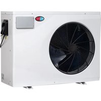
| Product Type | Heat Pump (Pool/Spa Heater) |
| Model | Apex 18 |
| Brand | EvoHeat |
| Heating Capacity (26°C Air / 26°C Water) | 18.0 kW |
| Smart Heating Capacity | 15 kW |
| COP (26°C Air / 26°C Water) | 19.2~7.1 |
| Dimensions (L x W x H) | 1045 x 432 x 660 mm |
| Net Weight | 73 kg |
| Power Supply | 220-240 V / 1 Phase / 50 Hz |
| Max Current | 16.5 A |
| Connection Type | Hardwired |
| Refrigerant | R32 |
| Water Connection Size | 40 mm PVC |
| Water Flow Volume | 83.3 L/min |
| Max Water Pressure Drop | 7 kPa |
| Fan Quantity | 1 |
| Noise Level at 1 m | 41.5 ~ 47.3 dB(A) |
| Noise Level at 10 m | 21.5 ~ 27.3 dB(A) |
| Operating Modes | Auto, Heating, Cooling |
| Performance Modes | Turbo, Smart, Silent |
| Control | Touchscreen with Wi-Fi (Inverter Life app) |
| Safety Features | Overload protection, RCD, auto shut-off on water interruption |
| Warranty | Refer to EvoHeat website for details |
Frequently Asked Questions - Apex 18 EvoHeat
User questions about Apex 18 EvoHeat
0 question about this device. Answer the ones you know or ask your own.
Ask a new question about this device
Download the instructions for your Heating in PDF format for free! Find your manual Apex 18 - EvoHeat and take your electronic device back in hand. On this page are published all the documents necessary for the use of your device. Apex 18 by EvoHeat.
USER MANUAL Apex 18 EvoHeat
natural_image
Front view of a black industrial air conditioning unit with grid pattern and control panel (no visible text or symbols)Contents
- Introduction ...... 2
- Dimensions....3
- Quick Start Guide....4
- Safety Instructions....6
- Installation....7
5.1 System Installation....7
5.2 Location of Installation 7
5.3 Airflow Clearances 8
5.4 Adequate Water Flow....8
5.5 Rubber Feet 8
5.6 Condensate Drain Barb....8
5.7 Drainage & Condensation....8
5.8 Plumbing 9
5.9 Water Pump Connection 9
5.10 Electrical Connection 9
5.11 Initial Start-Up 9
- Operation....10
6.1 The Controller .... 10
6.2 Operating Functions....10
6.2.1 Standby & Screen Lock/Unlock 10
6.2.2 Power Unit On/Off 11
6.2.3 Adjust Set Temperature 11
6.2.4 Switch between Real-Time Power Consumption or Heating Capacity Percentage 11
6.2.5 Changing Mode....11
6.2.6 Selecting a Performance Mode....11
6.2.4 System Time Settings 11
6.2.5 Setting a Timer....12
6.2.6 Defrosting....13
6.2.7 Temperature Display Conversion (°C to °F) 13
- Troubleshooting ....14
7.2 Frequency Conversion Board Fault Table 14
- Appendix ...... 15
8.1 Wi-Fi Operation....15
8.2 Wiring Diagrams....19
8.3 Parameter List....19
8.4 Cable Specifications....20
- Maintenance....23
9.1 F.A.Q....23
9.2 Advanced ...... 24
- Warranty....27
1. Introduction
This manual contains information relating to the installation, troubleshooting, operation, and maintenance of this EvoHeat unit. Instructions in this manual must always be followed. Failure to comply with these recommendations will invalidate the warranty. Should you have any questions or require technical support, call the EvoHeat office on 1300 859 933 to speak to our team.

Introducing the Evo Apex - boasting an impressive Coefficient of Performance (C.O.P.) of up to 20, it's engineered to provide energy-efficient heating for your pool or spa. Experience superior heating capabilities with our Turbo Heat mode, boosting heating capacity by up to 120% above standard levels. This results in faster heat-up times and efficient heat recovery, maintaining your optimal pool temperature with the lowest operating costs.
| Apex 11 | Apex 14 | Apex 18 | Apex 22 | Apex 26 | Apex 31 | Apex 40-3 | ||
| Performance Conditions: 26°C Air / 26°C Water | ||||||||
| Heating Capacity kW | 11.0 | 13.5 | 18.0 | 21.5 | 26.0 | 31.5 | 40.0 | |
| Heating Capacity (Smart) kW | 8.5 | 11.5 | 15 | 17.6 | 22 | 27 | 35 | |
| C.O.P | 20~7.3 | 19.6~7.5 | 19.2~7.1 | 20.5~7.2 | 20.3~7.2 | 19.6~7.4 | 19.8~7.2 | |
| Performance Conditions: 15°C Air / 26°C Water | ||||||||
| Heating Capacity | kW | 7.3 | 9.0 | 12.0 | 14.5 | 18.0 | 22.0 | 28.5 |
| Heating Capacity (Smart) | kW | 6.1 | 7.3 | 10 | 12 | 14.8 | 18 | 24 |
| C.O.P | 8.5~5.5 | 7.9~5.2 | 8~5 | 8.8~5.2 | 9.3~5.3 | 8.1~5.3 | 8~4.9 | |
| Performance Conditions: 35°C Air / 28°C Water | ||||||||
| Cooling Capacity | kw | 5.0 | 6.3 | 10 | 11.3 | 13 | 15 | 19.5 |
| TECHNICAL DATA | ||||||||
| Power Supply | 220-240/1/50 | 380-415/3/50 | ||||||
| Max. Current per phase A | 10 | 12.5 | 16.5 | 18.5 | 20.5 | 24 | 12.5 | |
| Connection Type | 15amp | 15amp | Hardwired | Hardwired | Hardwired | Hardwired | Hardwired | |
| Fan Quantity | 1 | 1 | 1 | 1 | 1 | 1 | 1 | |
| Fan Speed | RPM | 400-800 | 500-800 | 500-800 | 400-800 | 400-800 | 400-700 | 400-720 |
| Noise at 1M | dB(A) | 37.7~44.8 | 37.8~45.9 | 41.5~47.3 | 41.9~49.5 | 39.7~49.8 | 42.1~50.3 | 41.5~50.5 |
| Noise at 10M | dB(A) | 17.7~24.8 | 17.8~25.9 | 21.5~27.3 | 21.9~29.5 | 19.7~29.8 | 22.1~30.3 | 21.5~30.5 |
| Refrigerant | R32 | |||||||
| PVC Water Connection | mm | 40 | ||||||
| Water Flow Volume | L/min | 50 | 58.3 | 83.3 | 125 | 150 | 183.3 | 250 |
| Max. Water Pressure Drop | kPa | 4 | 5 | 7 | 8 | 12 | 16 | 22 |
| Net Dimensions (LxWxH) mm | 910×432×660 | 945×432×660 | 1045×432×660 | 1195×432×760 | 1072×536×956 | 1264×536×956 | 1364×536×956 | |
| Net Weight | kg | 63 | 65 | 73 | 82 | 100 | 122 | 147 |
This data pertains solely to the Evo heat pump and excludes auxiliary devices. The product specifications provided are accurate as of the print date but may change without notice. For the latest specifications, please consult an EvoHeat Specialist.
2. Dimensions
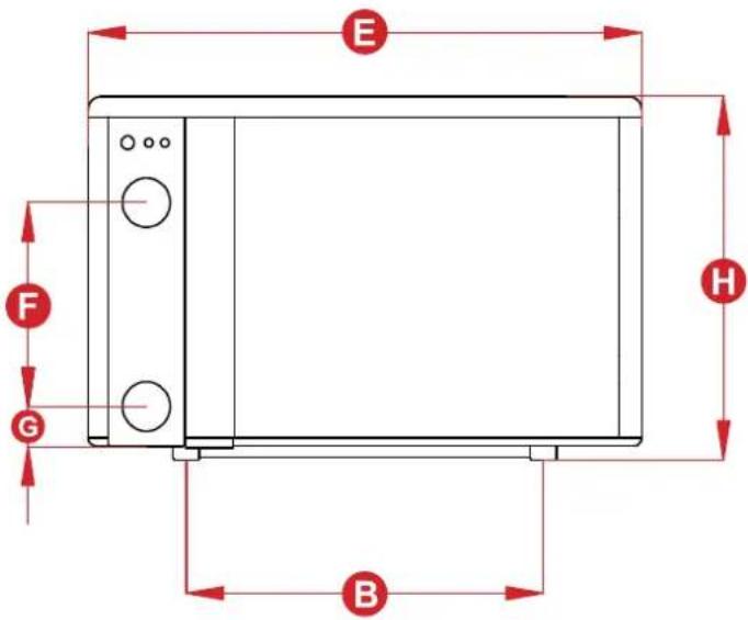
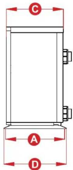
| Unit: mm | A B C | D (W) | E (L) | F G H (H) | |||||
| Apex 11 | 402 | 539 | 389 | 432 | 910 | 300 | 73 | 660 | |
| Apex 14 | 402 | 574 | 389 | 432 | 945 | 340 | 73 | 660 | |
| Apex 18 | 402 | 674 | 389 | 432 | 1045 | 380 | 73 | 660 | |
| Apex 22 | 402 | 824 | 389 | 432 | 1195 | 470 | 73 | 760 | |
| Apex 26 | 511 | 700 | 498 | 536 | 1072 | 550 | 73 | 956 | |
| Apex 31 | 511 | 891 | 498 | 536 | 1264 | 570 | 73 | 956 | |
| Apex 40-3 | 511 | 991 | 498 | 536 | 1364 | 670 | 73 | 956 |

IMPORTANT THINGS TO NOTE
- Ensure you meet the minimum clearances and recommended installation locations as outlined in the manual.
- All heat pump accessories are contained in a plastic bag inside the packaging of your heat pump unit.
PRE-INSTALLATION
- Position the heater on a level pad in the desired location on the pool water return line (as shown in the example image below).
- Install the supplied antivibration rubber pads under the feet of the unit.
- Install the supplied condensation barb to the underside of the unit and direct the condensation to an appropriate drainage point.

flowchart
graph LR
    A["Water pump"] --> B["Filter"]
    B --> C["3 Way Valve"]
    C --> D["1 Piece"]
    D --> E["PO2/POH"]
    E --> F["Cold in"]
    F --> C
    G["Pool Suction"] --> B
    H["Pool Return"] --> D
AIRFLOW CLEARANCES
Ensure the heater is installed in a well-ventilated area with plenty of fresh air, a minimum gap between walls/fences etc of 700mm on the sides and 1500mm front clearance.

PLUMBING INSTALLATION
NOTE: Evo heat pumps standard plumbing fitting size can accept 32mm or 50mm NB PVC pipe for connection to the pool or spa filtration plumbing.
- Attach the supplied barrel unions to the cold inlet and hot outlet (hand tighten).
- Use plumbing tape and ensure the 'O' ring is in position when sealing.
-
Make the plumbing connections and brace pipework where necessary.
-
Install a 3-way valve at the cold-water inlet and create a bypass by connecting a "T" piece to the heated line.
WATER PUMP CONNECTION
NOTE: there are 3 connection options for activation of the heat pump/water pump:
- Remote on/off – for connection to external pool automation (signal input)
- Water Pump - 230V connection point for dedicated water pump
- Dry Contact - connection for chlorinators with dry contact capabilities (signal output)
ELECTRICAL CONNECTION
NOTE: Electrical connection should only be completed by licenced personnel and in accordance with all relevant Australian Standards, applicable laws and local legislations.
- Remove the external cover to the electrical terminal by removing the screws at the bottom of the right-hand panel and the terminal cover panel.
- Feed the electrical cable in through the conduit nipple and attach the electric supply wires to the applicable Active Neutral and Earth connections located in the electrical terminal.
- To complete the electrical connection, install electrical conduit, UF cable or other suitable means as specified (as permitted by local electrical authorities) and connect the cable to a dedicated power supply branch circuit equipped with the appropriate size circuit breaker, or time delay fuse protection.
INITIAL STARTUP & COMMISSIONING
NOTE: The water pump must be running and water circulating through the heat pump for the system to operate.
- Turn on your water filter pump and check for water leaks and verify flow to and from the pool.
- Turn on the electrical power supply to the EvoHeat unit.
- Hold the Lock (🔒) button for 3 seconds to light the screen, then press the Power (💡) button to power on the heat pump.
- Press the Lock (🔒) button to select a mode, continue pressing the button until the Auto icon 📋 appears for automatic temperature control.
- Go back to the main menu, press the + or - arrow keys to adjust the target temperature settings. Leave the new temperature idle on the screen for 5 seconds to automatically save the adjustment.
- After the system has been running for approximately 5 minutes, check the Temperature Differential (TD) of the entering cold water to the exiting heated water.
a. On the main screen, the larger numbers on the top of the display refer to the inlet water temperature. The smaller numbers below this refer to the outlet water temperature.
b. Review the inlet and outlet water temperatures and adjust the water flow by opening or closing the 3-way valve installed at the cold-water inlet to achieve a target TD of approximately 2^ C (ex. 26^ C inlet water and 28^ C outlet water).
- If there is any interruption to water flow (i.e. when the water pump is turned off), the unit will automatically turn off and display an E03 error code – no water flow. This is normal and the system will restart once water flow is reinstated.
Initial heat up times will vary depending on the size of your pool, environmental conditions and the capacity of the system installed. After installation please allow the unit and pool pump to run continuously until the desired pool water temperature is reached (it may take several days for the pool to initially reach the set temperature).
Once the pool water reaches the desired set temperature, the unit will shut off. The unit will automatically restart (provided your pool pump is running) when the pool temperature falls more than 1^ C below the desired set temperature.
4. Safety Instructions

Installation, repair, or relocations must only be done by a fully qualified technician. If done incorrectly there is a number of hazards that can occur including fire, electric shock, water leakage and injury.
- A circuit breaker must be installed for the unit.
- Ensure the unit has a good power connection and earthing to avoid the risk of electrical shocks.
- Do not use any means to accelerate the defrosting processor or to clean other than those recommended by EvoHeat.
- The unit must be stored in a room without any continuously operating ignition sources (for example: open flames, an operating gas appliance)
- Do not pierce or burn the unit.
- If the supply cord is damaged, it must be replaced by a qualified service agent.
- This appliance must be installed in accordance with national wiring regulations.
- Before obtaining access to terminals all supply circuits must be disconnected.
The unit is equipped with an over-load protection system. After a previous stoppage, the unit will not start for at least 3 minutes.
Be aware that refrigerants may not contain an odour.
An all-pole disconnection device must be incorporated which as at least 3mm clearances in all poles, a leakage current that may exceed 10mA, residual current device (RCD) having a rated residual operating current not exceeding 30mA and disconnection must be incorporated in the fixed wiring in accordance with the wiring rules.

WARNING
THIS PRODUCT CONTAINS A BUTTON BATTERY
If swallowed, a lithium button battery can cause severe or fatal injuries within 2 hours.
Keep batteries out of reach of children.
If you think batteries may have been swallowed or placed inside any part of the body, seek immediate medical attention.
Installation
- The unit should be installed, operated and stored in a room with a floor area larger than 30m2.
- The installation of pipe-work should be kept to a minimum 30m2
- Spaces where refrigerant pipes are present must comply with national gas regulations.
- Use supply wires suitable for 75°C
Transport
When transporting equipment containing flammable refrigerants:
- Comply with transport & local regulations
- Equipment must be stored safely in accordance with the instructions within this manual.
- Abide by any signage on the packaging
- The unit must be protected from damage and potential leak of the refrigerant charge.
*Caution: Single wall heat exchanger, not suitable for potable water connection.
5. Installation
5.1 System Installation
Upon receiving the unit, check the packaging for any obvious signs of damage. Inform EvoHeat immediately if there is any evidence of rough handling. When the heater has been removed from the packaging check the refrigerant gauge on the front panel of the unit. The gauge should be showing a pressure of approx. 10 – 20 on the outside red band – any less than this figure means there may be a leak in the refrigerant system, and you should immediately contact your EvoHeat Dealer.
Only the main unit and the water unit in the illustration are provided; the other items are necessary spare parts for the water system that are to be provided by customer or the installer.
When starting for the first time:
- Open valve and charge water.
- Make sure that the pump and the water-in pipe have been filled with water.
- Close the valve and start the unit.
The schematic diagram is for reference only. Please check the water inlet/outlet label on the heat pump while plumbing the unit.

flowchart
graph LR
    A["Water pump"] --> B["Filter"]
    B --> C["3 Way Valve"]
    C --> D["T Piece"]
    D --> E["Heat Input"]
    E --> F["Pool Return"]
    F --> G["Pool Suction"]
    G --> A

IMPORTANT: EvoHeat heat pumps MUST be connected by a licensed electrician. Under no circumstances should an unlicensed person attempt to install or repair an EvoHeat heat pump themselves. Heater electrical installation undertaken by an unlicensed installer will void the warranty. Correct installation is required to safe and efficient operation of your pool heater.
Before installation it is very important to ensure 5 variables are carefully checked to allow the unit to operate correctly.
- Heater Condition
- Location
- Clearances & Air Flow
- Adequate water flow & plumbing
• Correct electrical connection & supply
5.2 Location of Installation
Evo recommend the heat pump should ONLY be installed in an outdoor location with appropriate ventilation. Installing the heater indoors without adequate ventilation, or in a poorly ventilated enclosed space, will result in very poor performance and can, in extreme cases, damage the heater.
The Evo unit should be installed:
- At least 3.5m away from the water's edge.
- No greater than 7.5m from the water's edge (to avoid heat loss from the piping).
- No greater than 5m below the water level of the pool/spa.
Make sure the heat pump is not located where large amounts of water may run-off from a roof into the unit. Sharp sloping roofs without gutters will allow excessive amounts of rainwater mixed with debris from the roof to be forced through the unit. A water deflector may be needed to protect the heat pump.
Ensure the heat pump is not installed close to harsh or corrosive chemicals.
The heat pump should be installed on a flat level surface. If a suitable outdoor location is unavailable please contact EvoHeat for specialist technical advice.
5.3 Airflow Clearances

Ensure the heater is installed in a well-ventilated area with plenty of fresh air, a minimum gap between walls/fences etc of 1500mm on the sides and 500mm overhead clearance. At minimum gap of at least 50mm is required at the rear of the unit.
Leave sufficient space for unobstructed airflow into and out of the heater. Do not locate the heater in an enclosed area, or the discharged cold air will recirculate into the unit and consequently lower the heating efficiency as well as possibly icing up.
If the installation location does not comply with these suggested clearances, contact EvoHeat's Tech Support to discuss possible solutions.
5.4 Adequate Water Flow
All EvoHeat heat pumps have a factory pre-set internal water flow switch. If there is insufficient water flow the unit will not operate.
It is VITAL that there is sufficient water flow to the unit. Incorrect water flow can cause a loss of efficiency and possible damage to the unit. Optimal water flow rates are listed within this manual. It is imperative that water flow is kept as close as possible to these flow rates.
Before connecting the heater to the plumbing all piping must be thoroughly flushed to ensure no debris can enter the heater. Failure to remove pipe debris can jam or damage the flow switch and may cause damage to the heater. When cleaning the pool, it is advisable to turn off your heater as restricted water flow may cause the heater to shut down and indicate low water flow fault (E03 error) or high pressure fault (E01 Error).

A Variable speed pump or bypass valve and plumbing MUST be fitted to allow water flow to be adjusted through the heater. Do not direct connect a water pump with higher flow than required to the heat pump.
5.5 Rubber Feet
All EvoHeat units are provided with rubber feet which we highly recommend being installed. The rubber feet help reduce vibration of the unit and provide a space below the heat pump to install the drainage barbs.
5.6 Condensate Drain Barb
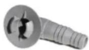
Fit the condensate drain barb into the 2 holes under the unit if you need to direct water away from the heater.
If the barb is too stiff, place it in hot water to soften.
5.7 Drainage & Condensation

During operation, water in the air condenses on the fins of the evaporator. In high humidity, the condensate may be several litres per hour, giving the impression that the unit is leaking. This process is a normal function of heat pumps.
The heater will automatically activate reverse cycle or de-icing mode when required which also increases condensate discharge. This normally occurs at temperatures below 8^ C. The condensate water will discharge through the base of the heater. As an option, a 20mm clear vinyl tube pipe can be connected by hand to the drain on the base of the unit to direct condensate water to an appropriate location.
NOTE
A quick way to verify that the water is condensation is to shut off the unit and keep the pool pump running. If the water stops running out of the base pan, it is condensation. Another method is to test the drain water for chlorine – if the is no chlorine present, then it's condensation
5.8 Plumbing
The unit's exclusive rated flow titanium heat exchanger requires no special plumbing arrangements except bypass (set the flow rate according to the nameplate). The water pressure drop is less than 10kPa at max.
Flow Rate
Since there is no residual heat or flame temperatures the unit does not need copper heat sink piping. PVC pipe can be run straight into the unit.
Location
Connect the unit in the pool pump discharge (return) line downstream of all filter and pool pumps, and upstream of any chlorinators, ozonators or chemical pumps.
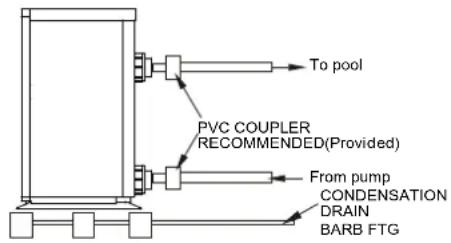
Standard models have slip glue fittings which accept 32mm or 50mm PVC pipe for connection to the pool or spa filtration piping. By using a 50NB to 40NB you can plumb 40NB.
Consider adding a quick coupler fitting at the unit's inlet & outlet to allow easy draining of the unit and to provide easier access should servicing be required. Ensure pipework connecting to the inlet/outlet unions is appropriately supported, any movement in this pipework can caused the rubber O-ring to pinch and leak.
5.9 Water Pump Connection
NOTE: there are 2 connection options for activation of heat pump/water pump:
- Remote on/off – for connection to external pool automation (“5” & “6” – signal input)
- Dry Contact – connection with EvoConnect/chlorinators with dry contact capabilities (“P1” & “P2” – signal output)

5.10 Electrical Connection

Always use a suitably qualified Electrician to perform any electrical work, they must read the manual before connecting.
Ensure all cabling, circuit breakers, and protections are of a suitable size and specification in accordance with electrical wiring legislation for the heater being installed. Ensure to check that there is adequate voltage and current available at the heater connection to run the unit.
Voltage range should be 220-240 volts for single phase, and 380-415 volts for 3 phase units. Voltage ranges outside these parameters will cause heater damage and void your warranty.
- Ensure power is disconnected during installation or service.
- Always comply with the national and local electrical codes and standards.
- Ensure the electrical cable size is adequate for heater requirements at the installation location.
- The heater must be equipped with a circuit breaker and isolation device.
- The circuit breaker must be installed between the heater and the water circulation pump if the water pump is hard-wired into the heater. Please note recommended circuit breaker sizes make no allowance for a water pump hard wired into the heater.
- The unit must be well earthed. Remove the right-side panel to access the electrical connection terminals of the heater. The electrical wiring diagram is affixed to the inside of the front panel or at the back of this manual.
5.11 Initial Start-Up
For the unit to heat the pool or spa, the filter pump MUST be running to circulate water through the heat exchanger.
- Turn on the filter pump. Check for water leaks and verify there is flow both to and from the pool.
- Turn of the unit's electrical power supply, then press the ON/OFF button on the unit to start it.
- After a few minutes of running, make sure the air leaving the unit is roughly between 5-10°C cooler.
- With the unit in operation, turn the filter pump off. The unit should then turn off automatically.
- Allow the unit and the pool pump to run for at least 24 hours a day until the desired temperature is reached. Once this temperature is reached, the unit will periodically slow down and turn off if the temperature is maintained for at least 45 minutes. The unit will automatically restart (as long as the pool pump is running) when the pool temperature drops more than 0.2^ C below set temperature.
6. Operation
6.1 The Controller


| 1 2 | 3 4 5 6 | 7 8 | ||||||
| Auto | Heating | Cooling | Wi-Fi | Real Time Power Consumption | Heating Capacity Percentage | Water Inlet | Water Outlet | Mode Status |
| 0.68 ^kW | ||||||||
6.2 Operating Functions
6.2.1 Standby & Screen Lock/Unlock
Standby Mode:
- The screen displays "0.00kW" when in standby and locked.
• The key lamp will be off.
Screen Lock:
- The screen automatically locks after 30 seconds of inactivity, showing "0%" or "0.00kW" if the heat pump is off.
• To manually lock, press and hold the lock button
( )for 3 seconds. The screen will dim.
Screen Unlock:
- Press and hold the lock button ( ) on 3 seconds to unlock the screen. The display will light up.
- Only after unlocking can other buttons be used.
- When the screen is locked, or there has been no operation for over 30 seconds, the screen will not be lit.
6.2.2 Power Unit On/Off
To turn the unit on, simply hold the lock button (💡) for 3 seconds to light the screen up, then press the power button (💡) to power on the heat pump.
6.2.3 Adjust Set Temperature
While the screen is unlocked, press the + or - buttons to adjust the set temperature as desired.
6.2.4 Switch between Real-Time Power Consumption or Heating Capacity Percentage
To change the display on the screen between either the real time power consumption, or the heating capacity percentage, hold both the power ( ) and plus button (+) for 5 seconds. *only available on single phase models
6.2.5 Changing Mode
To change the operating mode simply press the lock symbol until the desired mode is reached.
 | Auto | Auto: 12~40°C | Automatically switches between heating and cooling to maintain your desired pool temperature, ensuring optimal comfort with minimal effort. |
 | Heating | Heating: 18~40°C | Exclusively heats the pool to your set temperature, perfect for colder days or extending your swimming season. |
 | Cooling | Cooling: 12~30°C | Cools the pool water to a comfortable level, ideal for hot weather or maintaining a refreshing swim temperature. |
6.2.6 Selecting a Performance Mode
Performance Modes allow you to optimise the heat pump's operation for different needs. To select a performance mode, press the home button (and the selected mode will display on the screen:
 | Turbo Maximises heating or cooling for faster results. | |
| [ABX5] | Smart | Balances efficiency and performance, ideal for everyday use. |
 | Silent | Minimises noise for quieter operation, ideal for nighttime use. |
6.2.4 System Time Settings
The system time is the clock that is displayed on your unit. We recommend you adjust this to your local time if your unit is not aligned with this.
- Press and hold the timer button for 5 seconds.
- Use the "+" or "-" buttons to adjust the hour.
- Press the timer button ()L) again to switch to minute setting.
- Adjust the minutes with the "+" or "-" buttons.
- Press the timer button (☐) to confirm.
- Note: Press the power button (💡) to cancel the setting at any time.
To view the real-time display on your screen:
- When the machine is off, the real-time display appears in the top right corner.
- When the machine is on, press the clock button (☐) once to view the real time for 10 seconds.
6.2.5 Setting a Timer

No symbol No timer setting
Enter Timer Setting:
- Press and hold the Clock button (💡) for 10 seconds until you hear a beep.
- The Timer icon will start flashing, and the number "1" (indicating Timer 1) will also be flashing.
Set Timer On:
- Set Hour: With the hour digit flashing, use the "+" or "-" buttons to set the desired hour for the timer to turn on.
- Press the Clock button (💡) to confirm the hour.
- Set Minute: With the minute digit flashing, use the "+" or "-" buttons to set the desired minute.
- Press the Clock button (L) to confirm the minute.
- The "1" will stop flashing once the Timer On time is set, and the Timer On icon will be displayed.
Set Timer Off:
• After setting the Timer On, the Timer Off icon and the number "0" will start flashing.
- Set Hour: Use the "+" or "-" buttons to select the hour for the timer to turn off.
- Press the Clock button (☐) to confirm the hour.
- Set Minute: The minute digit will flash. Use the "+" or "-" buttons to select the minute.
- Press the Clock button (☐) to confirm the minute.
- The number "0" will stop flashing once the Timer Off time is set, and the Timer Off icon will remain displayed.
Finalise Timer Settings:
- Press the Clock button (☑) once more to confirm both Timer On and Timer Off settings.
• The display will show the timer icons based on your settings.
6.2.5.1 Timer Symbol Meanings
Understanding Timer Icons:
- Both Timer On and Timer Off icons: Indicates that the timer is set to turn on and off daily.
- Only Timer On icon: Indicates that the timer is set to turn on daily, with no timer set for turning off.
- Only Timer Off icon: Indicates that the timer is set to turn off daily, with no timer set for turning on.
- No icons: No timer is set.
| Icon | Timer On | Timer Off | Description |
  | Timer on every day | Timer off every day | Daily Timer On and Off: The timer is set to turn on and off at the specified times every day. |
| [85BA]and 0 alternate display | Timer on every day | Timer off one time | Daily Timer On and One-Time Timer Off: The timer is set to turn on at the specified time every day, but will turn off only once at the specified time. |
  | Timer on every day | No timer off | Daily Timer On Only: The timer is set to turn on at the specified time every day, with no timer set to turn off. |
 and 1 alternate display and 1 alternate display | Timer on one time | Timer off every day | One-Time Timer On and Daily Timer Off: The timer is set to turn on once at the specified time and will turn off every day at the specified time. |
 | No timer on | Timer off every day | No Timer On and Daily Timer Off: No timer is set to turn on, but the timer will turn off every day at the specified time. |
| Board | Timer on one time | Timer off one time | One-Time Timer On and Off: The timer is set to turn on and off once at the specified times. |
 | Timer on one time | No timer off | One-Time Timer On and No Timer Off: The timer is set to turn on once at the specified time, with no timer set to turn off. |
 | No timer on | Timer off one time | No Timer On and One-Time Timer Off: No timer is set to turn on, but the timer will turn off once at the specified time. |
| No symbol | No timer on | No timer off | No Timer Set:No timer is set to turn on or off. |
6.2.6 Defrosting
Auto-Defrost: During Defrosting: The defrosting icon (💡) will flash while the heat pump is defrosting. When defrosting is complete, the icon will stop flashing.
Compulsory Defrost: When the heat pump is heating, press the Home (♠) and Minus (-) buttons together for 5 seconds to start compulsory defrosting. The defrosting icon will flash during the process and stop once defrosting is finished.
Note: Ensure there is at least a 30-minute interval between defrosting cycles, and the compressor should run for more than 10 minutes in heating mode before defrosting again.
6.2.7 Temperature Display Conversion (°C to °F)
Press the Plus (+) and Minus (-) buttons together for 5 seconds to switch between Celsius and Fahrenheit.
7. Troubleshooting
7.2 Frequency Conversion Board Fault Table
Code Elimination Methods
| E3 No water protection | |
| E5 | Power supply exceeds operation range |
| E6 | Excessive temp difference between inlet and outlet water (Insufficient water flow protection) |
| Eb | Ambient temperature too high or too low protection |
| Ed Anti-freezing reminder | |
OFF Customer Control Switch DIN2 Disconnect
| E1 High pressure protection | |
| E2 Low pressure protection | |
| E4 | Phase loss protection (three-phase model only) |
| E7 | Water outlet temp too high or too low protection |
| E8 | High exhaust temp protection |
| EA | Evaporator overheat protection (only at cooling mode) |
| P0 | Controller communication failure |
| P1 | Water inlet temp sensor failure |
| P2 | Water outlet temp sensor failure |
| P3 | Gas exhaust temp sensor failure |
| P4 | Heating (Evaporator) coil pipe temp sensor |
| P5 | Gas return temp sensor failure |
| P6 | Cooling (Titanium heat exchanger) coil pipe temp sens |
P7 Ambient temp sensor failure
| P8 | Cooling plate sensor failure |
| P9 | Current sensor failure |
PA Restart memory failure
| F1 | Compressor drive module failure |
| F2 | PFC module failure |
F3 Compressor start failure
| F4 | Compressor running failure |
| F5 | Inverter board over current protection |
F6 Inverter board overheat protection
| F7 | Current protection |
| F8 | Cooling plate overheat protection |
F9 Fan motor failure
| Fb | Capacitor no charging protection |
| FA | PFC module over current protection |
8888 Communication failure
8. Appendix
8.1 Wi-Fi Operation

Please ensure during the initial setup process that:
- Check Wi-Fi Network: Ensure your Wi-Fi network name and password are correct.
- Ensure Proximity: Keep your router, mobile phone, and device close to each other.
- Router Configuration: Confirm that the router is set to 2.4 GHz, not 5 GHz.
DOWNLOAD THE APP & CREATE AN ACCOUNT
- Download the Inverter Life app from your device's application store.

Apple
https://apps.apple.com/gb/app/id14477
85325

Android
https://play.google.com/store/apps/details?id=
com.InverterLife
- Register and create an account with your mobile number or email address.
- Set a name for your family and choose a room to set the device up in.
CONNECTION TO APP
- Ensure your phone is connected to your home's Wi-Fi network.
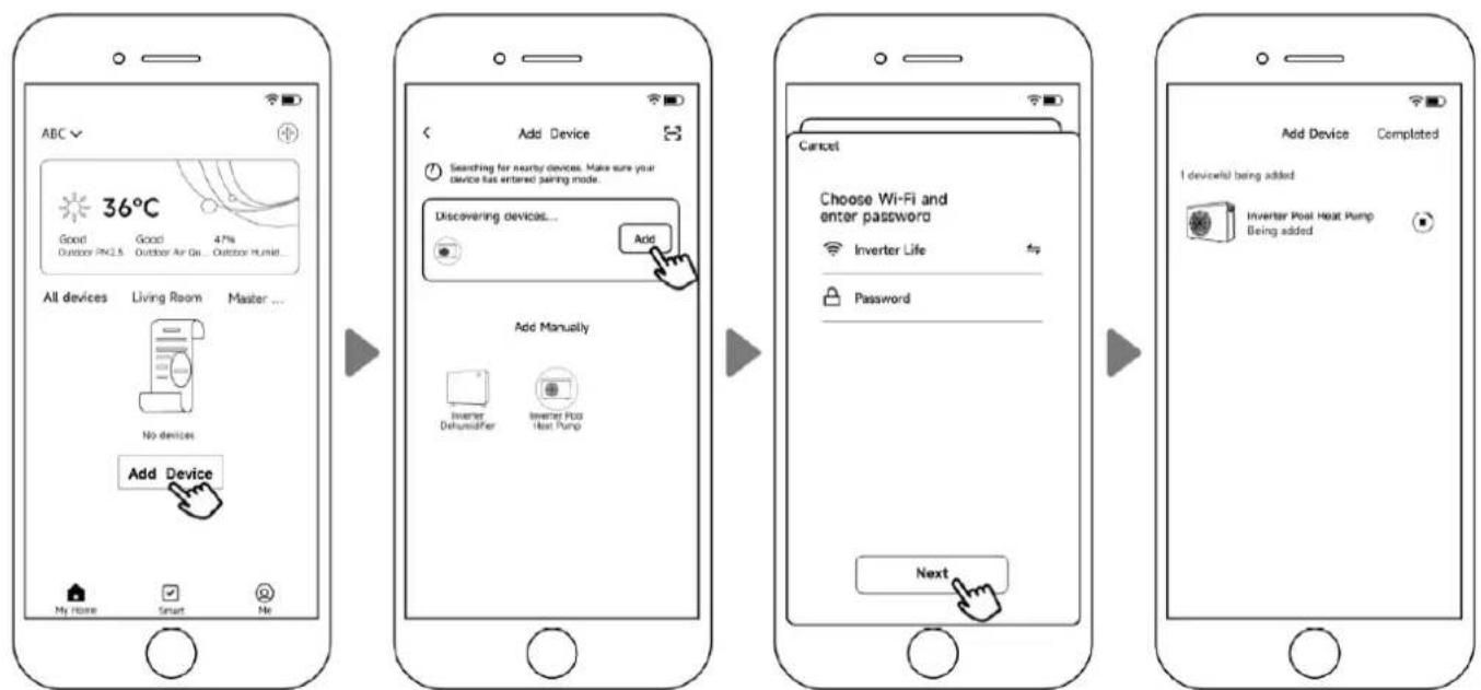
Connection Mode 1: Auto Discovery (Bluetooth)
-
Ensure the Bluetooth function is enabled on your phone.
-
On the heat pump, press and hold the POWER (⏻) button for 3 seconds until the WIFI icon is flashing rapidly on the screen, indicating the device is in Wi-Fi bonding status.
-
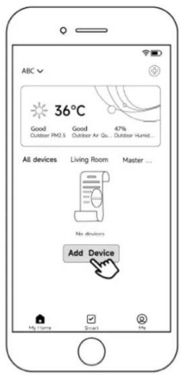
On the app, press 'Add Device' and wait for the app to search for your heat pump, when it appears on the screen press 'Add' and then follow the instructions on the screen to complete the binding procedure. You will need to know your home Wi-Fi's password to enter it again in the app to complete the setup.
Note: It can take some time for the app to scan the heat pump, please be patient during this step.
flowchart
graph LR
    A["ABC ✓ 36°C"] --> B["Add Device"]
    B --> C{Searching for nearby devices. Make sure your device has entered joining mode.}
    C --> D["Discovering devices..."]
    D --> E["Add Manually"]
    E --> F["Inverter Dehumather"]
    E --> G["Inverter Pool Heat Pump"]
    F --> H["Cancel"]
    G --> H
    H --> I["Choose Wi-Fi and enter password"]
    I --> J["Inverter Life"]
    I --> K["Password"]
    K --> L["Next"]
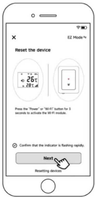
Connection Mode 2: EZ Connect Mode
- On the heat pump, press and hold the POWER (Button for 3 seconds until the WIFI icon is flashing rapidly on the screen, indicating the device is in Wi-Fi bonding status.
- Select the 'Inverter Pool Heat Pump' option under Add Manually and follow the on-screen prompts to reset your device and establish the connection.




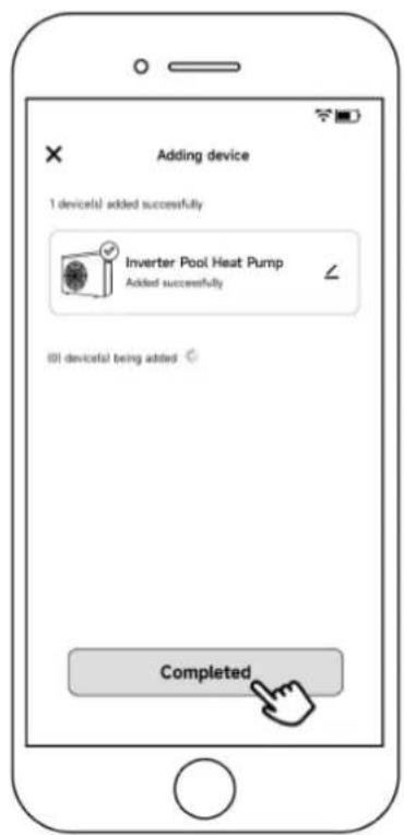
Connection Mode 3: AP Mode (or to rebind your device after a network password change)
- On the heat pump, press and hold the POWER (Button for 10 seconds until the WIFI icon is flashing rapidly on the screen, indicating the device is in Wi-Fi bonding status.
- Follow the on-screen prompts to connect your device to your home network, then it will guide you through resetting to finalise the connection.

SHARING YOUR DEVICE WITH FAMILY
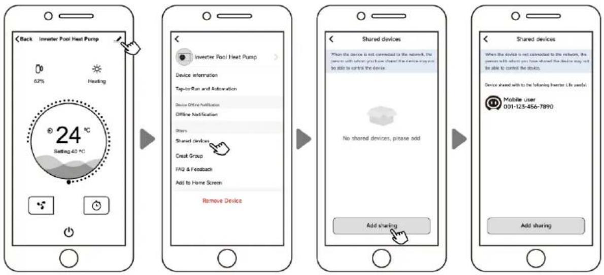
To allow your family members to control the device, have them register on the app first. Then, open the app, select the device, and tap the "Settings" icon. Navigate to "Shared devices" and tap "Add sharing". Enter their details and confirm. Your family members will now be able to see and control the heat pump from their app.
flowchart
graph LR
    A["Back Inverter Pool Heat Pump 62% Heating"] --> B["Setting 40 °C 24°C"]
    B --> C["Device information Tap-to-Run and Automation Device Online Notification Offline Notification Stores Shared devices Creat Group FAQ & Feedback Add to Home Screen Remove Device"]
    C --> D["Shared devices When the device is not connected to the network, the person with what you have shared the device may not be able to control the device. No shared devices, please add Add sharing"]
    D --> E["Shared devices When the device is not connected to the network, the person with what you have shared the device may not be able to control the device. Device shared with to be following Inverter Life users! Mobile user 001-125-456-7890 Add sharing"]
8.2 Wiring Diagrams
Power Supply: 220-240V

flowchart
graph LR
    A["Distribution Box (Customer prepare)"] --> B["Breaker"]
    C["Power Supply 220-240V 50Hz Earthing"] --> B
    B --> D["Fuse"]
    D --> E["Power Cord"]
    E --> F["Heat Pump Wiring Board"]
    style A fill:#f9f,stroke:#333
    style C fill:#f9f,stroke:#333
    style F fill:#ccf,stroke:#333
Power Supply: 380-415V

flowchart
graph LR
    A["Distribution Box (Customer prepare)"] --> B["Fuse"]
    B --> C["Breaker Breaker"]
    C --> D["Power Cord"]
    D --> E["Heat Pump Wiring Board"]
    E --> F["Live wire 1"]
    E --> G["Live wire 2"]
    E --> H["Live wire 3"]
    E --> I["Neutral wire"]
    E --> J["Ground wire"]
    K["Power Supply 380-415V 50Hz"] --> L["R"]
    K --> M["W"]
    K --> N["B"]
    K --> O["N"]
    P["Earthing"] --> Q["⊕"]
    Q --> R["Fuse"]
    R --> S["Breaker Breaker"]
    S --> T["Fuse"]
    T --> U["Breaker Breaker"]
    U --> V["Fuse"]
    V --> W["Breaker Breaker"]
    W --> X["Fuse"]
    X --> Y["Breaker Breaker"]
    Y --> Z["Fuse"]
    Z --> AA["Breaker Breaker"]
    AA --> AB["Fuse"]
    AB --> AC["Breaker Breaker"]
    AC --> AD["Fuse"]
    AD --> AE["Breaker Breaker"]
    AE --> AF["Fuse"]
    AF --> AG["Breaker Breaker"]
    AG --> AH["Fuse"]
    AH --> AI["Breaker Breaker"]
    AI --> AJ["Fuse"]
    AJ --> AK["Breaker Breaker"]
    AK --> AL["Fuse"]
    AL --> AM["Breaker Breaker"]
    AM --> AN["Fuse"]
    AN --> AO["Breaker Breaker"]
    AO --> AP["Fuse"]
    AP --> AQ["Breaker Breaker"]
    AQ --> AR["Fuse"]
    AR --> AS["Breaker Breaker"]
    AS --> AT["Fuse"]
    AT --> AU["Breaker Breaker"]
    AU --> AV["Fuse"]
    AV --> AW["Breaker Breaker"]
    AW --> AX["Fuse"]
    AX --> AY["Breaker Breaker"]
    AY --> AZ["Fuse"]
    AZ --> BA["Breaker Breaker"]
    BA --> BB["Fuse"]
    BB --> BC["Breaker Breaker"]
    BC --> BD["Fuse"]
    BD --> BE["Breaker Breaker"]
    BE --> BF["Fuse"]
    BF --> BG["Breaker Breaker"]
    BG --> BH["Fuse"]
    BH --> BI["Breaker Breaker"]
    BI --> BJ["Fuse"]
    BJ --> BK["Breaker Breaker"]
    BK --> BL["Fuse"]
    BL --> BM["Breaker Breaker"]
    BM --> BN["Fuse"]
    BN --> BO["Breaker Breaker"]
    BO --> BP["Fuse"]
    BP --> BQ["Breaker Breaker"]
    BQ --> BR["Fuse"]
    BR --> BS["Breaker Breaker"]
    BS --> BT["Fuse"]
    BT --> BU["Breaker Breaker"]
    BU --> BV["Fuse"]
    BV --> BW["Breaker Breaker"]
    BW --> BX["Fuse"]
    BX --> BY["Breaker Breaker"]
8.3 Parameter List
To check the parameters, press Home (♂) and Plus (+) together for 5 seconds to enter the parameter menu.
The display will show P0 followed by a value, for example, P0 0. This would show that the water pump is running continuously.
To scroll between the different parameters, while in the parameter checking mode, press the Plus (+) or Minus (-) button.
To adjust a parameter, while in the parameter checking mode, press Home (💡) to adjust the parameter value, then use the Plus (+) or Minus (-) buttons to adjust the values. Once the change has been made, press the Home (💡) button again to save changes and exit. To exit Parameter checking mode, press the Power (💡) button once.
| No. | Content | Adjustable Range | Step Length |
| P0 | Water Pump Operating Mode | 0: Continuous1: Temperature Control2: Time/Temperature Control | 1 |
| P1 | Time Setting (Available only when water pump mode is set to "2") | 10 ~ 120 min | 5 min |
| P2 | Compressor Continuous Running Time Between Defrost Cycles | 30 ~ 90 min | 1 min |
| P3 | Defrost Entry Temperature | -17 ~ 0°C / 1 ~ 32°F | 1C / 1F |
| P4 | Maximum Defrost Duration | 1 ~ 12 min | 1 min |
| P5 | Defrost Exit Temperature | 8 ~ 30°C / 46 ~ 86°F | 1C / 1F |
8.4 Cable Specifications
| Apex 11 | Apex 14 | Apex 18 | Apex 22 | Apex 26 | Apex 31 | Apex 40-3 | ||
| Breaker | Rated Current (A) | 12.0 | 15.0 | 20.0 | 22.5 | 24.5 | 28.5 | 15.0 |
| Rated Residual Action Current (mA) | 30 | 30 | 30 | 30 | 30 | 30 | 30 | |
| Max Input Current (A) | 10.0 | 12.5 | 16.5 | 18.5 | 20.5 | 24.0 | 12.5 | |
| Fuse (A) | 12.0 | 15.0 | 20.0 | 22.5 | 24.5 | 28.5 | 15.0 | |
| Power Cord ( mm^2 ) | 3 x 2.5 | 3 x 2.5 | 3 x 2.5 | 3 x 4 | 3 x 4 | 3 x 6 | 5 x 2.5 | |
| Signal Cable ( mm^2 ) | 3 x 0.5 | 3 x 0.5 | 3 x 0.5 | 3 x 0.5 | 3 x 0.5 | 3 x 0.5 | 3 x 0.5 | |
NOTE: The data above is applicable to power cords that are 5 meters or shorter. If the power cord exceeds 5 meters in length, the wire diameter must be increased. The signal cable can be extended to a maximum length of 50 meters.
8.5 Heating Priority Diagram (Optional): 1
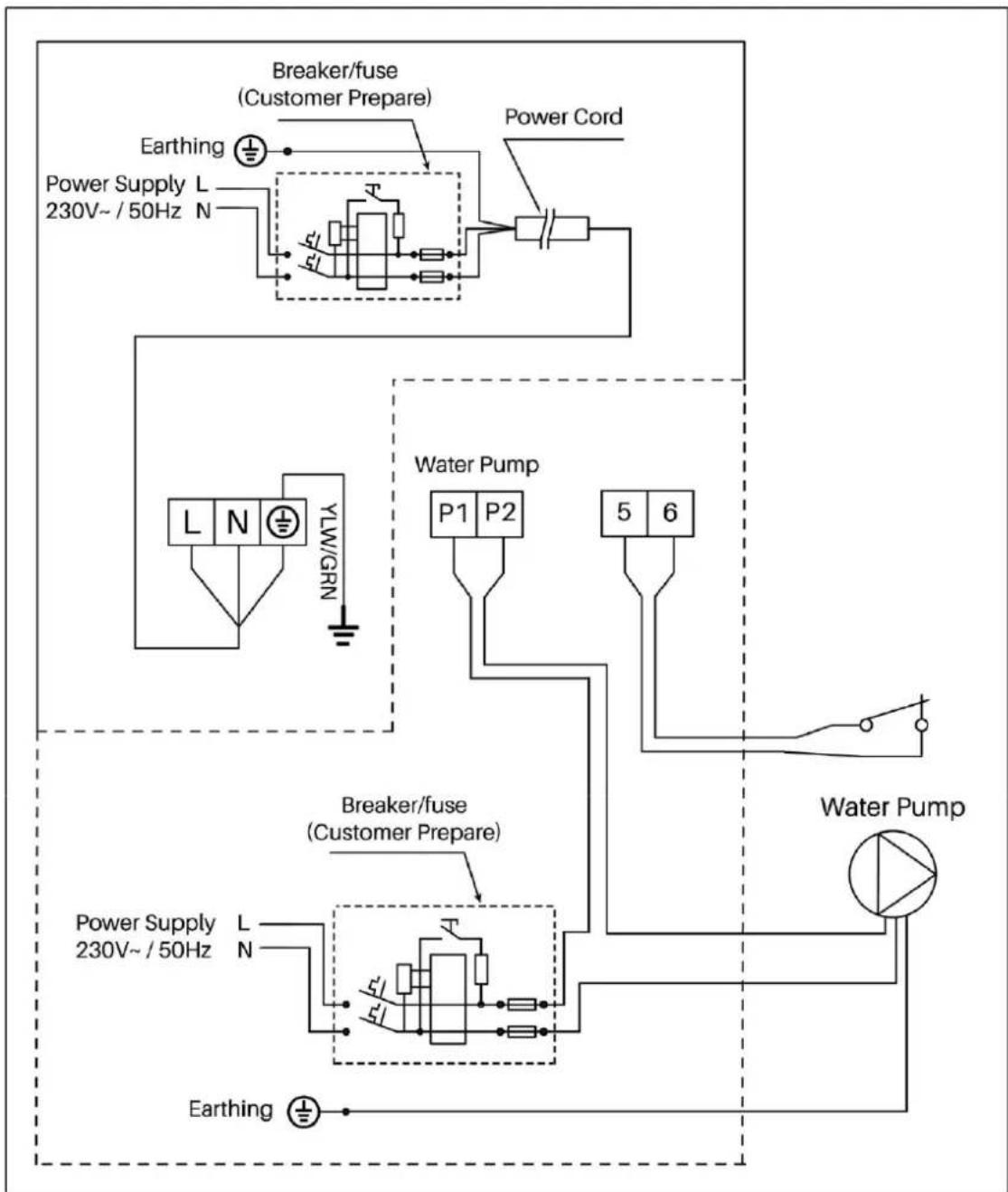
For Water Pump: Voltage 230V, Capacity ≤ 500W
flowchart
graph TD
    A["Earthing"] --> B["Breaker/fuse (Customer Prepare)"]
    B --> C["Power Supply L 230V~ / 50Hz N"]
    C --> D["Power Supply L 230V~ / 50Hz N"]
    D --> E["Water Pump P1 P2 5 6"]
    E --> F["Water Pump"]
    F --> G["Water Pump"]
    G --> H["Power Supply L 230V~ / 50Hz N"]
    H --> I["Breaker/fuse (Customer Prepare)"]
    I --> J["Power Supply L 230V~ / 50Hz N"]
    J --> K["Water Pump"]
    K --> L["Water Pump"]
    L --> M["Power Supply L 230V~ / 50Hz N"]
    M --> N["Water Pump"]
    N --> O["Power Supply L 230V~ / 50Hz N"]
    O --> P["Water Pump"]
    P --> Q["Power Supply L 230V~ / 50Hz N"]
    Q --> R["Water Pump"]
    R --> S["Power Supply L 230V~ / 50Hz N"]
    S --> T["Water Pump"]
    T --> U["Power Supply L 230V~ / 50Hz N"]
    U --> V["Water Pump"]
If your machine has terminals 5 and 6:
Use the customer remote control switch connector to enable automation control via a 2-wire dry contact connection, which will only control the unit's On/Off function.
A jumper is installed by default. If the jumper is loose or disconnected, "OFF" will be displayed.
Note: The components within the dotted box are optional and may not be included before production. For specific wiring details, please refer to the actual machine.
8.6 Heating Priority Diagram (Optional): 2
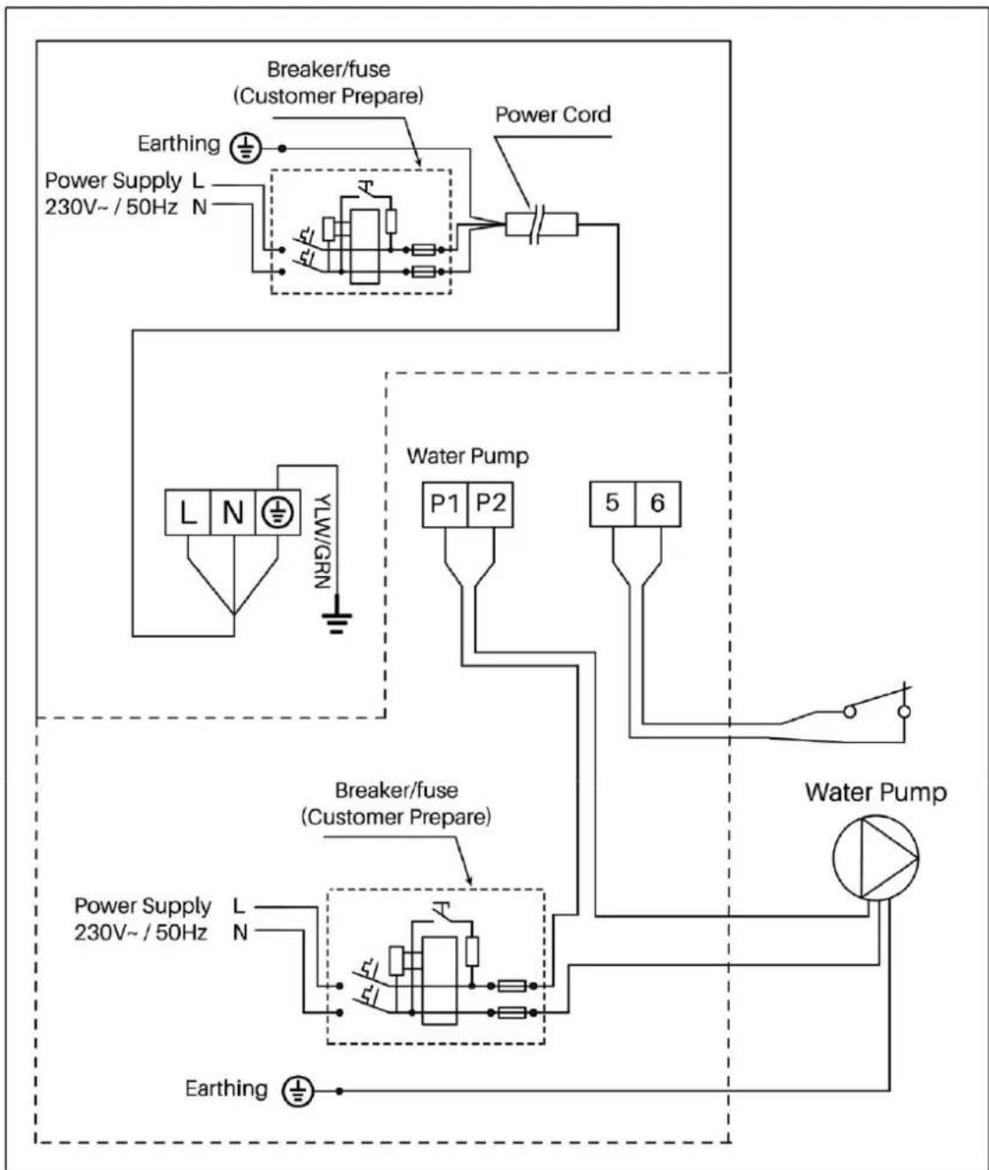
For Water Pump: Voltage 230V, Capacity > 500W
flowchart
graph TD
    A["Earthing"] --> B["Breaker/fuse (Customer Prepare)"]
    B --> C["Power Supply L 230V~ / 50Hz N"]
    C --> D["Power Supply L 230V~ / 50Hz N"]
    D --> E["Water Pump P1 P2 5 6"]
    E --> F["Water Pump"]
    F --> G["Water Pump"]
    G --> H["Power Supply L 230V~ / 50Hz N"]
    H --> I["Breaker/fuse (Customer Prepare)"]
    I --> J["Power Supply L 230V~ / 50Hz N"]
    J --> K["Water Pump"]
    K --> L["Water Pump"]
    L --> M["Power Supply L 230V~ / 50Hz N"]
    M --> N["Water Pump"]
    N --> O["Power Supply L 230V~ / 50Hz N"]
    O --> P["Water Pump"]
    P --> Q["Power Supply L 230V~ / 50Hz N"]
    Q --> R["Water Pump"]
    R --> S["Power Supply L 230V~ / 50Hz N"]
    S --> T["Water Pump"]
    T --> U["Power Supply L 230V~ / 50Hz N"]
    U --> V["Water Pump"]
Note: The components within the dotted box are optional and may not be included before production. For specific wiring details, please refer to the actual machine.
If your machine has terminals 5 and 6:
Use the customer remote control switch connector to enable automation control through a 2-wire dry contact connection. This will only control the unit's On/Off function.
A jumper is installed by default. If the jumper is loose or disconnected, "OFF" will be displayed.
9. Maintenance
9.1 F.A.Q
SHOULD I CHECK MY UNIT REGULARLY?
We recommend you do an annual maintenance check to avoid potential issues and damage to your heat pump.
ANNUAL MAINTENANCE
It is recommended that the minor maintenance be performed every 12 months by the dwelling occupant or if uncomfortable with completing this EvoHeat recommend this work to be carried out by an EvoHeat Authorised contractor. The minor maintenance includes:
- Inspection of the unit's operation...This includes:
- Unit is reaching set temperature.
-
Visible water leaks from unit besides condensation (test water for chlorine or other pool chemicals)
o Temperature difference between the inlet and outlet temperatures on the display whilst the unit is operational.
○ Isolate unit power and remove any debris from around the evaporator and unit to prevent any restriction to airflow. (brush out evaporator coil with a soft brush in a downwards motion to prevent bending or damaging the evaporator fins) -
Conduct a visual inspection of all plumbing and electrical connections.
- Check the condensate drain line to ensure it is not blocked. If so unblock/remove the restriction from the drain. This is generally attached to a plastic barb at the base of the unit.
- Conduct a general external clean of the unit with a damp cloth.
DO I NEED TO GET MY UNIT SERVICED?
It is recommended that you get your EvoHeat unit serviced every two years by your local certified air conditioning or refrigeration technician. If your unit is located in a coastal area, more frequent maintenance may be necessary.
During the service, they will check the operational pressures of the refrigeration system and give the unit and fins a good clean to ensure maximum performance.
TWO YEAR SERVICE
It is recommended that this maintenance is carried out by EvoHeat Authorised personnel. Just as a car needs regular servicing, your heat pump also requires a service to maintain efficiency and ensure long-term performance.
Phone EvoHeat Service on 1300 859 933 for our closest Accredited Service Agent.
Note: only genuine replacement parts should be used on this water heater. The service includes the following actions:
• All items listed in the Annual Maintenance
- Removal of unit covers to inspect operation of parts and internal leaks
• Check/tighten Heat exchanger Nut and Olive
- Check Fan operation
- Check Current draw of compressor and if it is in range
- Check Electrical resistance
- Check Electrical components for carbon build up, loose wiring etc.
- Wash out Evaporator Coil
• Vacuum Drain to ensure no blockage/restrictions
9.2 Advanced
CHECK THE AREA GENERAL WORK AREA
| Prior to beginning work on systems containing flammable refrigerants, safety checks are necessary to ensure that the risk of ignition is minimised. For repair to the refrigerating system, the following precautions shall be complied with prior to conducting work on the system. prolonged period of no usage. | All maintenance staff and others working in the local area shall be instructed on the nature of work being carried out. Work in confined spaces shall be avoided. The area around the workspace shall be sectioned off. Ensure that the conditions within the area have been made safe by control of flammable material. | |
| PRESENCE OF FIRE EXTINGUISHER WORK PROCEDURES | ||
| If any hot work is to be conducted on the refrigeration equipment or any associated parts, appropriate fire extinguishing equipment shall be available to hand. Have a dry powder or CO2 fire extinguisher adjacent to the charging | Work shall be undertaken under a controlled procedure to minimise the risk of a flammable gas or vapour being present while the work is being performed. | |
| CHECKING FOR PRESENCE OF REFRIGERANT | VENTILATED AREA | |
| The area shall be checked with an appropriate refrigerant detector prior to and during work, to ensure the technician is aware of potentially flammable atmospheres. Ensure that the leak detection equipment being used is suitable for use with flammable refrigerants, i.e. non-sparking, adequately sealed or intrinsically safe. | Ensure that the area is in the open or that it is adequately ventilated before breaking into the system or conducting any hot work. A degree of ventilation shall continue during the period that the work is carried out. The ventilation should safely disperse any released refrigerant and preferably expel it externally into the atmosphere. prolonged period of no usage. | |
| CABLING | DETECTION OF FLAMMABLE REFRIGERANTS | |
| Check that cabling will not be subject to wear, corrosion, excessive pressure, vibration, sharp edges or any other adverse environmental effects. The check shall also consider the effects of aging or continual vibration from sources such as compressors or fans. | Under no circumstances shall potential sources of ignition be used in the searching for or detection of refrigerant leaks. A halide torch (or any other detector using a naked flame) shall not be used. | |
| REPAIR TO INTRINSICALLY SAFE COMPONENTS | LABELLING | |
| Do not apply any permanent inductive or capacitance loads to the circuit without ensuring that this will not exceed the permissible voltage and current permitted for the equipment in use.Intrinsically safe components are the only types that can be worked on while live in the presence of a flammable atmosphere.The test apparatus shall be at the correct rating. Replace components only with parts specified by the manufacturer. Other parts may result in the ignition of refrigerant in the atmosphere from a leak. | Equipment shall be labelled stating that it has been decommissioned and emptied of refrigerant. The label shall be dated and signed. Ensure that there are labels on the equipment stating the equipment contains flammable refrigerant. | |
| NO IGNITION SOURCES | No person carrying out work in relation to a refrigeration system which involves exposing any pipe work that contains or has contained flammable refrigerant shall use any sources of ignition in such a manner that it may lead to the risk of fire or explosion. All possible ignition sources, including cigarette smoking, should be kept sufficiently far away from the site of installation, repairing, removing and disposal, during which flammable refrigerant can possibly be released to the surrounding space. Prior to work taking place, the area around the equipment is to be surveyed to make sure that there are no flammable hazards or ignition risks. No Smoking signs shall be displayed. | |
| CHARGING PROCEDURES | In addition to conventional charging procedures, the following requirements shall be followed.Ensure that contamination of different refrigerants does not occur when using charging equipment. Hoses or lines shall be as short as possible to minimise the amount of refrigerant contained in them.Cylinders shall be kept upright.Ensure that the refrigeration system is earthed prior to charging the system with refrigerant.Label the system when charging is complete (if not already).Extreme care shall be taken not to overfill the refrigeration system.Prior to recharging the system, it shall be pressure tested with OFN. The system shall be leak tested on completion of charging but prior to commissioning. A follow up leak test shall be carried out prior to leaving the site. The safety wire model is 5*20_5A/250VAC, and must meet the explosion-proof requirements. | |
| CHECKS TO THE REFRIGERATION EQUIPMENT | Where electrical components are being changed, they shall be fit for the purpose and to the correct specification. At all times the manufacturer's maintenance and service guidelines shall be followed. If in doubt consult the manufacturer's technical department for assistance.The following checks shall be applied to installations using flammable refrigerants:The charge size is in accordance with the room size within which the refrigerant containing parts are installed;The ventilation machinery and outlets are operating adequately and are not obstructed; If an indirect refrigerating circuit is being used, the secondary circuit shall be checked for the presence of refrigerant;Marking to the equipment continues to be visible and legible. Markings and signs that are illegible shall be corrected;Refrigeration pipe or components are installed in a position where they are unlikely to be exposed to any substance which may corrode refrigerant containing components, unless the components are constructed of materials which are inherently resistant to being corroded or are suitably protected against being so corroded. | |
| CHECKS TO ELECTRICAL DEVICES | Repair and maintenance to electrical components shall include initial safety checks and component inspection procedures. If a fault exists that could compromise safety, then no electrical supply shall be connected to the circuit until it is satisfactorily dealt with. If the fault cannot be corrected immediately but it is necessary to continue operation, an adequate temporary solution shall be used. This shall be reported to the owner of the equipment, so all parties are advised. | Initial safety checks shall include:That capacitors are discharged: this shall be done in a safe manner to avoid possibility of sparking;That there no live electrical components and wiring are exposed while charging, recovering or purging the system;That there is continuity of earth bonding. |
| REPAIRS TO SEALED COMPONENTS | 1. During repairs to sealed components, all electrical supplies shall be disconnected from the equipment being worked upon prior to any removal of sealed covers, etc. If it is necessary to have an electrical supply to equipment during servicing, then a permanently operating form of leak detection shall be located at the most critical point to warn of a potentially hazardous situation.Particular attention shall be paid to the following to ensure that by working on electrical components, the casing is not altered in such a way that the level of protection is affected. This shall include damage to cables, excessive number of connections, terminals not made to original specification, damage to seals, incorrect fitting of glands, etc.Ensure that apparatus is mounted securely.Ensure that seals or sealing materials have not degraded such that they no longer serve the purpose of preventing the ingress of flammable atmospheres. Replacement parts shall be in accordance with the manufacturer's specifications.NOTE: The use of silicon sealant may inhibit the effectiveness of some types of leak detection equipment.Intrinsically safe components do not have to be isolated prior to. | |
| LEAK DETECTION METHODS | The following leak detection methods are deemed acceptable for systems containing flammable refrigerants.Electronic leak detectors shall be used to detect flammable refrigerants, but the sensitivity may not be adequate, or may need re-calibration. (Detection equipment shall be calibrated in a refrigerant-free area.) Ensure that the detector is not a potential source of ignition and is suitable for the refrigerant used. Leak detection equipment shall be set at a percentage of the LFL of the refrigerant and shall be calibrated to the refrigerant employed and the appropriate percentage of gas (25 % maximum) is confirmed.Leak detection fluids are suitable for use with most refrigerants but the use of detergents containing chlorine shall be avoided as the chlorine may react with the refrigerant and corrode the copper pipe-work.If a leak is suspected, all naked flames shall be removed/extinguished.If a leakage of refrigerant is found which requires brazing, all of the refrigerant shall be recovered from the system, or isolated (by means of shut off valves) in a part of the system remote from the leak. Oxygen free nitrogen (OFN) shall then be purged through the system both before and during the brazing process. | |
| REMOVAL ANDEVACUATION | When breaking into the refrigerant circuit to make repairs or for any other purpose conventional procedures shall be used.However, it is important that best practice is followed since flammability is a consideration.The following procedure shall be adhered to:Remove refrigerant;Purge the circuit with inert gas;Evacuate;Purge again with inert gas;Open the circuit by cutting or brazing. | The refrigerant charge shall be recovered into the correct recovery cylinders. The system shall be "flushed" with OFN to render the unit safe. This process may need to be repeated several times.Compressed air or oxygen shall not be used for this task.Flushing shall be achieved by breaking the vacuum in the system with OFN and continuing to fill until the working pressure is achieved, then venting to atmosphere, and finally pulling down to a vacuum. This process shall be repeated until no refrigerant is within the system. When the final OFN charge is used, the system shall be vented down to atmospheric pressure to enable work to take place. This operation is absolutely vital if brazing operations on the pipe-work are to take place.Ensure that the outlet for the vacuum pump is not close to any ignition sources and there is ventilation available. working on them. | |
| RECOVERY | When removing refrigerant from a system, either for servicing or decommissioning, it is recommended good practice that all refrigerants are removed safely.When transferring refrigerant into cylinders, ensure that only appropriate refrigerant recovery cylinders are employed. Ensure that the correct number of cylinders for holding the total system charge is available. All cylinders to be used are designated for the recovered refrigerant and labelled for that refrigerant (i.e. special cylinders for the recovery of refrigerant). Cylinders shall be complete with pressure relief valve and associated shut-off valves in good working order. Empty recovery cylinders are evacuated and, if possible, cooled before recovery occurs.The recovery equipment shall be in good working order with a set of instructions concerning the equipment that is at hand and shall be suitable for the recovery of flammable refrigerants. In addition, a set of calibrated weighing scales shall be available and in good working order. Hoses shall be complete with leak-free disconnect couplings and in good condition. Before using the recovery machine, check that it is in satisfactory working order, has been properly maintained and that any associated electrical components are sealed to prevent ignition in the event of a refrigerant release. Consult manufacturer if in doubt. | The recovered refrigerant shall be returned to the refrigerant supplier in the correct recovery cylinder, and the relevant Waste Transfer Note arranged. Do not mix refrigerants in recovery units and especially not in cylinders.If compressors or compressor oils are to be removed, ensure that they have been evacuated to an acceptable level to make certain that flammable refrigerant does not remain within the lubricant. The evacuation process shall be carried out prior to returning the compressor to the suppliers. Only electric heating to the compressor body shall be employed to accelerate this process. When oil is drained from a system, it shall be carried out safely. | |
| DECOMMISSIONING | Before carrying out this procedure, it is essential that the technician is completely familiar with the equipment and all its detail. It is recommended good practice that all refrigerants are recovered safely.Prior to the task being carried out, an oil and refrigerant sample shall be taken in case analysis is required prior to re-use of reclaimed refrigerant. It is essential that electrical power is available before the task is commenced.a) Become familiar with the equipment and its operation.b) Isolate system electrically.c) Before attempting the procedure ensure that:- Mechanical handling equipment is available, if required, for handling refrigerant cylinders;- All personal protective equipment is available and being used correctly;- The recovery process is always supervised by a competent person;- Recovery equipment and cylinders conform to the appropriate standards.d) Pump down refrigerant system, if possible.e) If a vacuum is not possible, make a manifold so that refrigerant can be removed from various parts of the system.f) Make sure that cylinder is situated on the scales before recovery takes place.g) Start the recovery machine and operate in accordance with manufacturer's instructions.h) Do not overfill cylinders. (No more than 80 % volume liquid charge).i) Do not exceed the maximum working pressure of the cylinder, even temporarily.j) When the cylinders have been filled correctly and the process completed, make sure that the cylinders and the equipment are removed from site promptly and all isolation valves on the equipment are closed off.k) Recovered refrigerant shall not be charged into another refrigeration system unless it has been cleaned and checked. | ||
10. Warranty

Refer to the EvoHeat website for warranty details
Australia: https://evoheat.com.au/warranty-terms/
South East Asia: http://evoheat.com.sg/warranty/
REGISTER YOUR WARRANTY

EvoHeat highly recommend customers complete their warranty details online to ensure efficient warranty claim processing. To register your warranty, scan our QR Code or head to our website and fill in the Warranty Registration Form: https://evoheat.com.au/warranty-registration/
-
Warranty terms are from date of purchase.
-
This warranty excludes any defect or injury caused by or resulting from misuse, abuse, neglect, accidental damage, improper voltage, vermin infestation, incompetent installation, any fault not attributable to faulty manufacture or parts, any modifications which affect the reliability or performance of the unit.
-
This warranty does not cover the following:
a) Natural Disasters (hail, lightening, flood, fire etc.)
b) Damage resulting from any animal or creature (including vermin, reptiles and insects)
c) Rust or damage to exterior coatings, materials, and cabinet caused by corrosive atmosphere or weather/environmental conditions.
d) When serviced by an unauthorised person without the permission of Evo Industries.
e) When a unit is installed by an unqualified person.
f) When failure occurs due to improper or incorrect installation.
g) Where failure occurs due to failure of any other equipment connected in relation with the EvoHeat unit (e.g. power supply).
h) Where failure occurs due to improper maintenance or misuse (refer Operating Instructions).
i) Where the unit has not had its three-year general maintenance service performed by a certified plumber. Proof of this service will be required for warranty claims beyond three years.
j) 'No Fault Found' service calls where the perceived problem is explained within the operation instructions.
k) Costs associated with delivery, handling, freighting, or damage to the product in transit.
I) Where the unit has been relocated from its originally installed location.
- If warranty service is required, you should:
a) Contact Evo Industries Australia on 1300 859 933 or via our Contact page on our website.
b) Provide a copy of your receipt as proof of purchase.
c) Have completed the online Service Request Form via the website www.evoheat.com.au/service-request/
-
Onsite technical service is available within the normal operating area of your Evo Authorised Service Agents. Service outside this area will incur a traveling fee.
-
Unless otherwise specified to the purchaser, the benefits conferred by this express warranty and additional to all other conditions, warranties, rights and remedies expressed or implied by the Trade Practices Act 1974 and similar consumer protection provisions contained in legislation of the States and Territories and all other obligations and liabilities on the part of the manufacturer or supplier and nothing contained herein shall restrict or modify such rights, remedies, obligations or liabilities.


- Contents
- Introduction
- Dimensions
- IMPORTANT THINGS TO NOTE
- PRE-INSTALLATION
- AIRFLOW CLEARANCES
- PLUMBING INSTALLATION
- WATER PUMP CONNECTION
- ELECTRICAL CONNECTION
- INITIAL STARTUP & COMMISSIONING
- Safety Instructions
- WARNING
- THIS PRODUCT CONTAINS A BUTTON BATTERY
- Installation
- Transport
- Installation
- System Installation
- Location of Installation
- Airflow Clearances
- Adequate Water Flow
- Rubber Feet
- Condensate Drain Barb
- Drainage & Condensation
- Plumbing
- Flow Rate
- Location
- Water Pump Connection
- Electrical Connection
- Initial Start-Up
- Operation
- The Controller
- Operating Functions
- Standby & Screen Lock/Unlock
- Standby Mode:
- Screen Lock:
- Screen Unlock:
- Power Unit On/Off
- Adjust Set Temperature
- Switch between Real-Time Power Consumption or Heating Capacity Percentage
- Changing Mode
- Selecting a Performance Mode
- System Time Settings
- Setting a Timer
- Enter Timer Setting:
- Set Timer On:
- Set Timer Off:
- Finalise Timer Settings:
- Timer Symbol Meanings
- Understanding Timer Icons:
- Defrosting
- Temperature Display Conversion (°C to °F)
- Troubleshooting
- Frequency Conversion Board Fault Table
- Appendix
- Wi-Fi Operation
- DOWNLOAD THE APP & CREATE AN ACCOUNT
- CONNECTION TO APP
- Connection Mode 1: Auto Discovery (Bluetooth)
- Connection Mode 2: EZ Connect Mode
- Connection Mode 3: AP Mode (or to rebind your device after a network password change)
- SHARING YOUR DEVICE WITH FAMILY
- Wiring Diagrams
- Parameter List
- Heating Priority Diagram (Optional): 1
- If your machine has terminals 5 and 6:
- Heating Priority Diagram (Optional): 2
- Maintenance
- F.A.Q
- SHOULD I CHECK MY UNIT REGULARLY?
- ANNUAL MAINTENANCE
- DO I NEED TO GET MY UNIT SERVICED?
- TWO YEAR SERVICE
- Advanced
- Warranty
- Refer to the EvoHeat website for warranty details
- REGISTER YOUR WARRANTY
Brand : EvoHeat
Model : Apex 18
Category : Heating