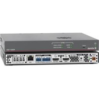
FOX3 T 201 - Video extender Extron - Free user manual and instructions
Find the device manual for free FOX3 T 201 Extron in PDF.


| Product Type | Fiber Optic Transmitter for HDMI, audio, RS-232, and IR signals |
| Dimensions | 1 inch (2.5 cm) high, half rack width |
| Weight | Not specified (typical for similar devices: approx. 0.5 kg) |
| Power Supply | External Extron Everlast power supply, 12 V, 2.0 A |
| Video Support | Uncompressed or visually lossless 4K up to 4096x2160 @ 60 Hz with 4:4:4 chroma sampling (over two fibers); supports HDMI 2.0, data rates up to 18 Gbps, Deep Color up to 12-bit |
| Audio Support | 2-channel LPCM audio; analog stereo audio embedding; audio gain adjustment (-18 dB to +24 dB) |
| Control Signals | Bidirectional RS-232 and IR pass-through over fiber |
| HDCP Compliance | HDCP 2.3 compliant; user-selectable HDCP authorization; Key Minder and EDID Minder |
| Fiber Optic Connectors | Two LC connectors with SFP modules; supports singlemode up to 20 km, multimode up to 500 m |
| Additional Features | Buffered HDMI loop-out, front panel USB config port, Ethernet monitoring and control, LinkLicense support, internal test pattern |
| Safety Class | Class 1 laser product (invisible light); FCC Class A; battery notice for internal battery |
| Environmental Operating Temperature | Maximum ambient: +122°F (+50°C) |
| Mounting Options | Tabletop, rack-mountable (half rack width), under-desk, or projector bracket |
| Warranty | 3 years parts and labor; Everlast power supply covered by 7-year warranty |
| Maintenance and Cleaning | Keep dust caps on optical transceivers when not in use; no specific cleaning instructions provided |
| Spare Parts and Repairability | Battery replacement requires return to Extron; service must be carried out by qualified personnel |
Frequently Asked Questions - FOX3 T 201 Extron
User questions about FOX3 T 201 Extron
0 question about this device. Answer the ones you know or ask your own.
Ask a new question about this device
Download the instructions for your Video extender in PDF format for free! Find your manual FOX3 T 201 - Extron and take your electronic device back in hand. On this page are published all the documents necessary for the use of your device. FOX3 T 201 by Extron.
USER MANUAL FOX3 T 201 Extron
Safety Instructions • English
WARNING: This symbol, 4, when used on the product, is intended to alert the user of the presence of uninsulated dangerous voltage within the product's enclosure that may present a risk of electric shock.
ATTENTION: This symbol, ⚠️ when used on the product, is intended to alert the user of important operating and maintenance (servicing) instructions in the literature provided with the equipment.
For information on safety guidelines, regulatory compliances, EMI/EMF compatibility, accessibility, and related topics, see the Extron Safety and Regulatory Compliance Guide, part number 68-290-01, on the Extron website, www.extron.com.
All trademarks mentioned in this guide are the properties of their respective owners.
The following registered trademarks (®), registered service marks (SM), and trademarks (TM) are the property of RGB Systems, Inc. or Extron (see the current list of trademarks on the Terms of Use page at www.extron.com):
| Registered Trademarks(®) |
| Extron, Cable Cubby, ControlScript, CrossPoint, DTP, eBUS, EDID Manager, EDID Minder, eLink, Flat Field, FlexOS, Glitch Free, Global Configurator, Global Scripter, GlobalViewer, Hideaway, HyperLane, IP Intercom, IP Link, Key Minder, LinkLicense, LockIt, MediaLink, MediaPort, NAV, NetPA, PlenumVault, PoleVault, PowerCage, PURE3, Quantum, ShareLink, Show Me, SoundField, SpeedMount, SpeedSwitch, StudioStation, System INTEGRATOR, TeamWork, TouchLink, V-Lock, VN-Matrix, VoiceLift, WallVault, WindoWall, XPA, XTP, XTP Systems, and ZipClip |
| Registered Service Mark(SM): S3 Service Support Solutions |
| Trademarks(TM) |
| AAP, AFL (Accu-RATE Frame Lock), ADSP (Advanced Digital Sync Processing), AVEdge, CableCover, CDRS (Class D Ripple Suppression), Codec Connect, DDSP (Digital Display Sync Processing), DMI (Dynamic Motion Interpolation), Driver Configurator, DSP Configurator, DSVP (Digital Sync Validation Processing), EQIP, Everlast, FastBite, Flex55, FOX, FOXBOX, IP Intercom HelpDesk, MAAP, MicroDigital, Opti-Torque, PendantConnect, ProDSP, QS-FPC (QuickSwitch Front Panel Controller), Room Agent, Scope-Trigger, SIS, Simple Instruction Set, Skew-Free, SpeedNav, Triple-Action Switching, True4K, True8K, VectorTM 4K, WebShare, XTRA, and ZipCaddy |
FCC Class A Notice
This equipment has been tested and found to comply with the limits for a Class A digital device, pursuant to part 15 of the FCC rules. The Class A limits provide reasonable protection against harmful interference when the equipment is operated in a commercial environment. This equipment generates, uses, and can radiate radio frequency energy and, if not installed and used in accordance with the instruction manual, may cause harmful interference to radio communications. Operation of this equipment in a residential area is likely to cause interference. This interference must be corrected at the expense of the user.
Battery Notice
This product contains a battery. Do not open the unit to replace the battery. If the battery needs replacing, return the entire unit to Extron (for the correct address, see the Extron Warranty section on the last page of this guide).
CAUTION: Risk of explosion. Do not replace the battery with an incorrect type. Dispose of used batteries according to the instructions.
Class 1 Laser Product
Any service to this product must be carried out by Extron and its qualified service personnel.
CAUTION: Using controls, making adjustments, or performing procedures in a manner other than what is specified herein may result in hazardous radiation exposure.
NOTE: For more information on safety guidelines, regulatory compliances, EMI/EMF compatibility, accessibility, and related topics, see the “Extron Safety and Regulatory Compliance Guide” on the Extron website.
Conventions Used in this Guide
Notifications
The following notifications are used in this guide:
DANGER:
WARNING: Potential risk of severe injury or death.
CAUTION: Risk of minor personal injury.
NOTE: A note draws attention to important information.
TIP: A tip provides a suggestion to make working with the application easier.
Software Commands
Commands are written in the fonts shown here:
^AR Merge Scene,,0p1 scene 1,1 ^B 51 ^W^C.0
[01] R000400300004000080000600 [02] 35 [17] [03]
Esc X1 *X17 *X20 *X23 *X21 CE ←
NOTE: For commands and examples of computer or device responses used in this guide, the character "e" is the number zero and "O" is the capital letter "o."
Computer responses and directory paths that do not have variables are written in the font shown here:
Reply from 208.132.180.48: bytes=32 times=2ms TTL=32
C:\Program Files\Extron
Variables are written in italics as shown here:
ping xxx.xxx.xxx.xxx -t
SOH R Data STX Command ETB ETX
Selectable items, such as menu names, menu options, buttons, tabs, and field names are written in the font shown here:
From the File menu, select New.
Click the OK button.
Specifications Availability
Product specifications are available on the Extron website, www.extron.com.
Extron Glossary of Terms
A glossary of terms is available at http://www.extron.com/technology/glossary.aspx.
Contents
Introduction....1
About this Guide....1
Product Description....1
Fiber Cable Transmission Modes 2
Extron LinkLicense.... 3
Features 3
Installation and Operation.... 5
Installation Overview 5
Rear Panel Features 5
Rear Panel Connections 5
Connector and Cable Details 10
HDMI Connectors....10
RS-232 and IR....11
TP Cable Termination and Recommendations .... 11
Front Panel Features....12
Operation 12
Reset....12
Configuration....14
EDID....14
HDCP....14
RS-232 Insertion.... 15
Audio Configuration....16
Audio Embedding....16
Audio Input Gain....16
Audio Input Configuration 16
Audio Mute....16
SIS Configuration and Control ......17
Host Control Ports....17
Rear Panel RS-232 Port 17
Front Panel Configuration USB Port......17
Ethernet (LAN) Ports 17
Establishing a Connection.... 18
Simple Instruction Set Control 19
Host-to-Unit Instructions....19
Device-Initiated Power-Up Message 19
Error Responses....19
Timeout....19
Using the Command and Response Table ..... 20
Common symbol definitions.... 20
Command and Response Table for
SIS Commands 22
Configuration Software ......26
Software/Firmware Installation 26
Connecting to PCS....28
Device Discovery Panel....28
TCP/IP Panel 29
Offline Device Preview....29
Software Overview....30
Software Menu 31
Device Menu.... 33
Internal Web Page 35
Accessing the Internal Web Page 35
Web Page Panels 36
Device Info Panel 36
Device Status Panel....37
Network Settings Panel 38
Firmware Panel 38
Roles and Permissions Panel....39
LinkLicense Panel 40
About the FOX3 T 201....41
Equipment Mounting 42
Mounting the Transmitter 42
Tabletop Use 42
Mounting kits....42
UL Rack-Mounting Guidelines 43
Introduction
WARNING: The FOX3 T 201 output continuous invisible light (Class 1 rated), which may be harmful to the eyes; use with caution.
This guide contains information about the Extron FOX3 T 201 fiber optic transmitter.
Product Description
The FOX3 T 201 transmitter is a ultra-high performance fiber optic extender for long haul transmission of the following over two fiber optic cables (see figure 1 on page 2):
- Uncompressed or visually lossless HDCP-compliant 4096x2160 or 3840x2160 (UHD) @ 60 Hz video HDMI video
• 2-CH LPCM audio
• RS-232 and IR control signals
The transmitter extends HDMI signals up to:
• 20 km (12.4 miles) for the singlemode cables
- 500 m (1640 feet) with 50 µm OM4 4700 MHz bandwidth laser optimized multimode cables
(see Fiber Cable Transmission Modes on page 2).
The transmitter converts the HDMI video, the selected audio, and the RS-232 serial communication into two proprietary data streams and outputs them as optical signals via fiber optic small form factor pluggable (SFP) modules on two LC connector to a compatible Extron FOX3 fiber optic receiver.
The transmitter has many controls, including audio adjustments, that are available under Remote RS-232 and USB port Simple Set Instruction (SIS) control and PCS.
NOTE: The FOX3 products are not compatible with legacy FOX, FOXBOX, FOX II, PowerCage 401 FOX, or PowerCage 1600 FOX products.
Fiber Cable Transmission Modes
The transmitter is further categorized by the type of fiber optic cable, multimode or singlemode, which defines the effective range of transmission:
Multimode — Long distance, up to 500 m (1640 feet) (depending on the fiber cable)
Singlemode — Very long distance, up to 20 km (12.4 miles)
NOTE: The multimode and singlemode units are physically and functionally identical, with the exception of the effective range of transmission. In this guide, any reference applies to either transmission mode unless otherwise specified.
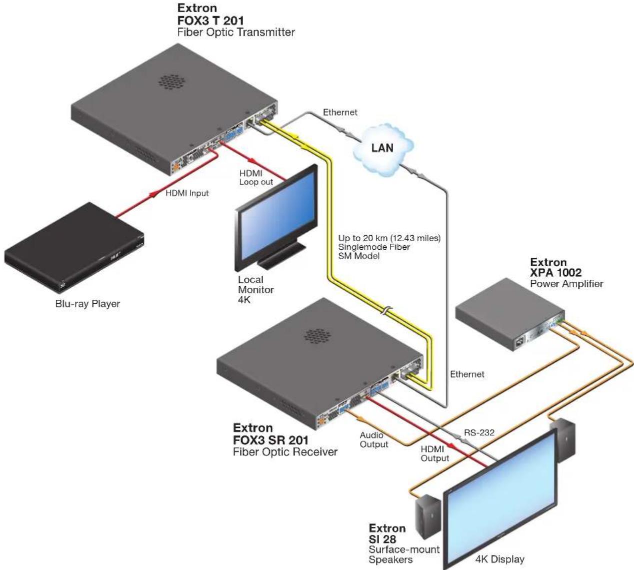
flowchart
graph TD
    A["Extron FOX3 T 201\nFiber Optic Transmitter"] -->|HDMI Input| B["Blu-ray Player"]
    A -->|HDMI Loop out| C["Local Monitor 4K"]
    A -->|Ethernet| D["LAN"]
    D --> E["Extron XPA 1002\nPower Amplifier"]
    E --> F["Extron SI 28\nSurface-mount Speakers"]
    F --> G["4K Display"]
    C --> H["Extron FOX3 SR 201\nFiber Optic Receiver"]
    H --> I["Audio Output"]
    H --> J["HDMI Output"]
    J --> K["RS-232"]
    K --> L["Extron XPA 1002\nPower Amplifier"]
    L --> M["Extron FOX3 SR 201\nFiber Optic Receiver"]
    M --> N["Local Monitor 4K"]
    style A fill:#f9f,stroke:#333
    style B fill:#ccf,stroke:#333
    style C fill:#cfc,stroke:#333
    style D fill:#fcc,stroke:#333
    style E fill:#cff,stroke:#333
    style F fill:#ffc,stroke:#333
    style G fill:#fcc,stroke:#333
    style H fill:#ffc,stroke:#333
    style I fill:#fcc,stroke:#333
    style J fill:#ffc,stroke:#333
    style K fill:#fcc,stroke:#333
    style L fill:#cff,stroke:#333
    style M fill:#ffc,stroke:#333
Figure 1. Typical FOX3 T 201 Transmitter Application
Extron LinkLicense
An Extron LinkLicense unlocks features that add convenience, expand system options, and enhance the capabilities of Extron products. Each LinkLicense can be purchased separately from the FOX3 device and activated as the need arises (A LinkLicense can be uploaded using Extron Toolbelt software and the Toolbelt Help File. See Software/Firmware Installation on page 26 to download Toolbelt).
LinkLicense upgrades available for the FOX3 transmitter include the following:
- Uncompressed Video Upgrade —
- This LinkLicense is enabled once and lasts for the life of the product.
- Allows the FOX3 devices to pass uncompressed 4K @ 60 Hz video on the second SFP module, enabling the highest video performance.
Features
- Transmits HDMI video, stereo audio, RS-232 control, and IR control signals over fiber optic cabling.
- Supports mathematically lossless 4K video up to 4096x2160 at 60 Hz with 4:4:4 chroma sampling over one fiber.
- Supports uncompressed 4K video up to 4096x2160 at 60 Hz with 4:4:4 chroma sampling over two fibers.
- Supported HDMI 2.0 specification features include data rates up to 18 Gbps and Deep Color up to 12-bit.
• HDCP 2.3 compliant. - Buffered HDMI input loop-through — Local HDMI output provides signals for a local display, enabling monitoring or sharing of content without the need for a separate distribution amplifier.
• Audio embedding — Analog stereo audio signals are converted to digital HDMI audio. - User-selectable HDCP authorization — Allows the transmitter to appear HDCP compliant or non-HDCP compliant to the connected source.
- Key Minder continuously verifies HDCP compliance for quick, reliable switching — Authenticates and maintains continuous HDCP encryption between input and output devices to ensure quick and reliable switching in professional AV environments.
- EDID Minder automatically manages EDID communication between connected devices — EDID Minder ensures that all sources power up properly and reliably output content for display.
- Audio gain and attenuation adjustment capability — Setting the level of gain or attenuation eliminates noticeable volume differences when switching between sources.
- Bidirectional RS-232 and IR signal transmission over fiber optic cabling for AV device control — Bidirectional RS-232 and IR control pass-through enables a remote device to be controlled without the need for additional cabling. Two fibers are required for bidirectional communications.
- LinkLicense Support — Extron LinkLicense unlocks features that add convenience, expand system functionality, and enhance the capabilities of Extron products.
- Front panel USB configuration port — Enables easy system configuration without having to access the rear panel.
- Ethernet monitoring and control — Enables control and proactive monitoring over a LAN, WAN, or the Internet.
- RS-232 control — Features an RS-232 serial port for control and configuration.
- Real-time status LED indicators for troubleshooting and monitoring — Front and rear panel LEDs verify signal presence, HDCP authentication, fiber link status, and power.
- Easy setup and commissioning with Extron's PCS - Product Configuration Software — Conveniently configures multiple products using a single software application.
- Internal color bars test pattern for calibration and setup — Simplifies setup and installation by providing a video signal when a source is unavailable.
- Compatible with Extron FOX3 Series matrix switchers — Creates HDCP-compliant signal distribution systems.
- JITC Certified — Successfully completed interoperability and information assurance testing for use in government applications and other mission-critical environments.
- Industry standard LC connectors provide reliable physical connectivity and precise fiber core alignment.
- Available as an 850 nm multimode model for moderate-range transmissions up to 500 m (1640 feet) and a 1310 nm singlemode model for extreme distances up to 20 km (12.4 miles).
- 1" (2.5 cm) high, half rack width mountable metal enclosure.
- External Extron Everlast power supply — Provides worldwide power compatibility, with high demonstrated reliability and low power consumption for reduced operating cost.
- Extron Everlast Power Supply is covered by a 7-year parts and labor warranty.
Installation and Operation
This section details the installation of the FOX3 T 201 transmitter, including:
• Installation Overview
• Rear Panel Features
- Connector and Cable Details
- Front Panel Features
- Operation
• Audio Configuration
Installation Overview
Follow these steps to install and set up an Extron FOX3 T 201 transmitter for operation:
- Turn off all of the equipment. Ensure that the video source and the output display are all turned off and disconnected from the power source.
- Mount the transmitter (see Equipment Mounting on page 42).
- Connect the cables and configure the units (see "Rear Panel Connections", starting below).
- Plug in the power supplies, then turn on the display and the input.
Rear Panel Features
Rear Panel Connections
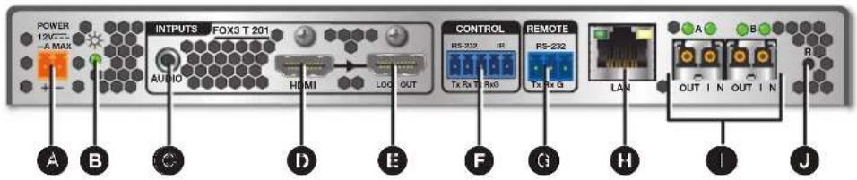
Figure 2. FOX3 T 201 Transmitter Rear Panel Features
A Power inlet
B Power LED
Audio input
D HDMI input
E HDMI Loop Out
F Control RS-232/IR port
Remote RS-232
H LAN Ethernet port
① SFP module and LEDs
J Reset button
Power inlet (see figure 2 on page 5) — Connect the external 12 V, 2.0 A power supply to the 2-pole captive screw inlet.
CAUTION: The DC output cables must be kept separate from each other while the power supply is plugged in. Remove power before wiring
- Cut the DC output cord to the length needed.
- Strip the jacket to expose 3/16 inch (5 mm) of the conductor wire (see figure 3).
- Ensure the connections have the correct polarity as shown in the figure above. The wire with ridges is the ground wire.
- Slide the exposed ends of the wire into the captive screw connector and secure by tightening the screws.
- Use the supplied tie wrap to strap the power cord to the extended tail of the connector.
ATTENTION:
B Power LED — The lit LED indicates power is applied and device is ready to transmit.
Audio input (see figure 2 on page 5)— Connect an audio input device to the Audio 3.5 mm audio jack.
NOTE: The analog audio input on this connector is in addition to the digital audio embedded in the HDMI inputs. See figure 4 to identify the connector tip, ring, and sleeve when making connections for the transmitter from existing audio cables. A mono audio connector consists of the tip and sleeve. A stereo audio connector consists of the tip, ring, and sleeve.
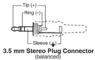
Figure 4. Audio Wiring Diagram
HDMI input — Connect a digital video input to this HDMI port. The transmitter also accepts embedded digital audio on this port (see HDMI Connectors on page 10 to use the included Extron Lock-It Lacing Bracket).
E HDMI Loop Out — If desired, connect a local monitor to this HDMI port.
F Control RS-232 and IR port — Connect a serial RS-232 signal, a modulated or unmodulated IR signal, or both to this 3.5 mm, 5-pole captive screw port for bidirectional RS-232 and IR communication (see RS-232 and IR on page 11 to wire the connector).
NOTES:
- To receive responses from the controlled device over RS-232 or IR, two fiber optic cables must be connected.
- The FOX3 system can pass RS-232 commands and responses at rates up to 115200 baud.
• RS-232 and IR can be active simultaneously.
Remote RS-232 port — For serial control of the transmitter, connect a host device, such as a computer or touch panel control, via the 3-pole captive screw port (see RS-232 and IR to wire this connector).
H LAN Ethernet port — Connect the transmitter to an Ethernet LAN or WAN via this RJ-45 port. Ethernet control allows the operator to configure the transmitter from a remote location. When connected to an Ethernet LAN or WAN, the transmitter can be accessed and operated from a computer running a standard Internet browser (see TP Cable Termination and Recommendations on page 11 to wire the connector).
- Link (green) LED — Indicates that the unit is properly connected to an Ethernet LAN. This LED should light steadily.
- Act (yellow) LED — Indicates transmission of data packets on the RJ-45 connector. This LED should blink as the unit communicates.
NOTE: This is not a pass-through LAN connection
① SFP module and LEDs — (see figure 2 on page 5)
WARNING: The units output continuous invisible light (Class 1 rated), which may be harmful to the eyes; use with caution. Plug the attached dust cap into the optical transceiver when the fiber optic cable is unplugged.
- Ensure the proper fiber cables for the transmitter and receiver pair are used. Typically, singlemode fiber has a yellow jacket and multimode cable has an orange or aqua jacket.
- See figure 5 for fiber cable connections. Connect the transmitter to a receiver in one of three ways:
- One way (transmitter to receiver) only, connect transmitter Outputs A (1) to receiver Inputs A (1).
- Two way (transmitter to receiver and return), connect transmitter Outputs A (①) to receiver Inputs A (①) and connect transmitter Outputs A (②) to receiver Inputs A (②).
- Output B is available to transmit a 4K @ 60 Hz uncompressed signal when the FOX3 4K @ 60 Hz Uncompressed Video LinkLicense is purchased.
1 Port A Out (required) — For all one-way video, audio, and serial communications from the transmitter to the receiver, connect a fiber optic cable to the Out LC port.
Connect the opposite end of this fiber optic cable to the Port A In LC port on the receiver or to any other compatible Extron FOX3 device.
② Port A In (optional) — For one-way serial communications from the receiver to the transmitter, connect a fiber optic cable to the In LC port.
Connect the opposite end of this fiber optic cable to the Port A Out LC port on a receiver or to any other compatible Extron FOX3 device.
SFP Link LEDs —
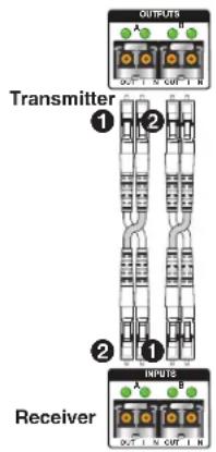
Figure 5. Connection
- Transmit Optical OUT LED lights solid green when powered and lights off when there is no power on the endpoint.
- Receive Optical IN LED lights solid green when light is present and lights off when there is no power or light present.
Reset button — Initiates three levels of resets (1, 4, and 5). Use a pointed stylus, ballpoint pen, or small screwdriver to access the recessed button (see Reset on page 12 for detailed reset information).
Connector and Cable Details
HDMI Connectors
HDMI signals run at a very high frequency and are especially prone to errors caused by bad video connections, too many adapters, or excessive cable length. To avoid the loss of an image or jitter, follow these guidelines:
- Limit or avoid the use of adapters.
- Use only cables specifically intended for HDMI or DVI signals.
To securely fasten an HDMI cable to a device:
- Plug the HDMI cable into the panel connection (see figure 6, ①).


Figure 6. Installing the LockIt Lacing Bracket
- Loosen the HDMI connection mounting screw from the panel enough to allow the LockIt lacing bracket to be placed over it (②). The screw does not have to be removed.
- Place the LockIt lacing bracket on the screw and against the HDMI connector, then tighten the screw to secure the bracket (③).
ATTENTION:
- Do not overtighten the HDMI connector mounting screw. The shield to which it fastens is very thin and can easily be stripped.
-
Ne serrez pas trop la vis de montage du connecteur HDMI. Le blindage auquel elle est attachée est très fin et peut facilement être dénudé.
-
Loosely place the included tie wrap around the HDMI connector and the LockIt lacing bracket (4).
-
While holding the connector securely against the lacing bracket, use pliers or similar tools to tighten the tie wrap, then remove any excess length (⑤).
RS-232 and IR
Figure 7 shows how to wire the Control (RS-232 and IR) connector.

Figure 7. Control and Sync Connectors Wiring
NOTE: The IR Tx and Rx line pair and the RS-232 Tx and Rx line pair must each cross once between this connector and the source or destination.
TP Cable Termination and Recommendations
It is vital that your Ethernet cable be the correct cable type and that it be properly terminated with the correct pinout. Ethernet links use Category (CAT) 3, 5e, or CAT 6, unshielded twisted pair (UTP) or shielded twisted pair (STP) cables, terminated with RJ-45 connectors. Ethernet cables are limited to a length of 328 feet (100 meters).
NOTES:
- Do not use standard telephone cables. Telephone cables do not support Ethernet or Fast Ethernet.
- Do not stretch or bend cables. Transmission errors can occur.
The cable used depends on your network speed. The unit supports 10 Mbps (10Base-T — Ethernet), 100 Mbps (100Base-T — Fast Ethernet), and 1000 Mbps (1000Base-T — IEEE 802.3ab) half-duplex and full-duplex Ethernet connections.
• 10Base-T Ethernet requires CAT 3 UTP or STP cable at minimum.
• 100Base-T Fast Ethernet requires CAT 5e UTP or STP cable at minimum.
- 1000Base-T Gigabit Ethernet requires CAT 5, CAT 5e, CAT 6, or CAT 7 UTP or STP cable.
The Ethernet cable must be terminated as a patch (straight-through) cable and must be properly terminated in accordance with the TIA/EIA T568-B wiring standard (see figure 8).
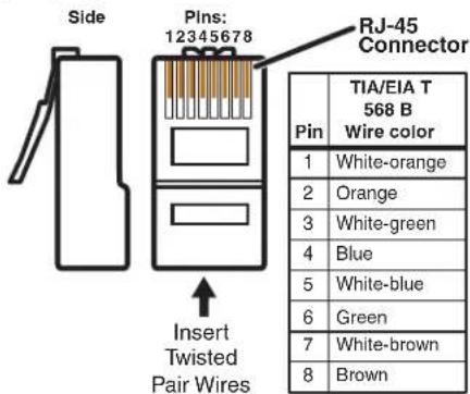
Figure 8. RJ-45 Connector and Pinout Tables
Front Panel Features
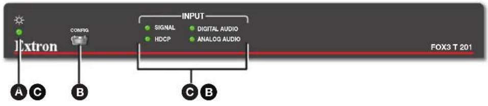
Figure 9. Transmitter Front Panel Features
A Power LED — The unit is receiving power and is operational.
B Configuration port — This USB mini-B port is used to configure the unit and to update firmware.
© Input LEDs
• Signal — Lights when the unit detects an input video signal.
- HDCP — Lights when the input signal is HDCP encrypted.
• Digital Audio — Lights when digital audio is selected.
- Analog Audio — Lights when analog audio input is selected.
Operation
After the transmitter, receiver, and the connected devices are powered up, the system is fully operational. If any problems are encountered, ensure all cables are routed and connected properly.
NOTE: Ensure that the video source and display are properly connected to the FOX3 transmitter and receiver, and power is applied to the FOX3 devices and the display before power is applied to the video source. If the other devices are not turned on before the video source, the image may not appear.
Configuration and operation of the transmitter is accomplished via SIS Configuration and Control starting on page 17, the Internal Web Page starting on page 35, and Configuration Software starting on page 26.
Reset
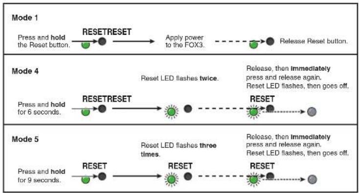
The rear panel Reset button initiates three levels of resets (numbered 1, 4, and 5). Use a pointed stylus, ballpoint pen, or small screwdriver to access the recessed button.
See the Reset Modes and figure 10 on page 13 for a summary of the resets.
ATTENTION:
Perform resets of the unit as follows (see figure 10):
flowchart
graph LR
    A["Press and hold the Reset button."] --> B["RESETRESET"]
    B --> C["Apply power to the FOX3."]
    C --> D["Release Reset button."]

    E["Press and hold for 6 seconds."] --> F["RESETRESET"]
    F --> G["Reset LED flashes twice."]
    G --> H["Release, then immediately press and release again. Reset LED flashes, then goes off."]

    I["Press and hold for 9 seconds."] --> J["RESET"]
    J --> K["Reset LED flashes three times."]
    K --> L["Release, then immediately press and release again. Reset LED flashes, then goes off."]
Figure 10. Resets
| Reset Modes | ||||
| Mode | Activation Result Purpose and Notes | |||
| Use Factory Firmware | 1 Hold in the recessed rear panelResetbutton while applying power to the unit. | The device reverts to the factory default firmware for a single power cycle. | Use to revert to the factory default firmware for a single power cycle if incompatibility issues arise with user-loaded firmware. All user files and settings are maintained. | |
| NOTE: Do not operate with the default firmware loaded by a mode 1 reset. Use it only to load the most current firmware to the device. | ||||
| Reset All IP Settings | *4 | Hold in the Resetbutton until the Power LED blinks twice (once at 3 seconds, again at 6 seconds). Then, release and press the Resetbutton again within 1 second*. | Sets the following back to factory default:Port mappingIP address (192.168.254.254)Subnet mask address (255.255.255.0)Gateway address (0.0.0.0)Turns DHCP off.The Power LED blinks four times. | Use to reset all IP settings back to factory defaults.Equivalent to SIS command 1ZQQQ (see Resets on page 24). |
| Reset to Factory Defaults | *5 | Hold in the Resetbutton until the Power LED blinks three times (once at 3 seconds, again at 6 seconds, again at 9 seconds). Then, release and press the Resetbutton again within 1 second*. | A complete reset to factory defaults (except the firmware):Does everything mode 4 does.Clears port configurations.Resets all IP options.Clears all user settings.Resets all passwords.Clears all files from the unit.The Power LED blinks four times. | Use to start over with default configuration and uploading, and also to replace events.Equivalent to SIS command ZQQQ (see Resets). |
| NOTES:*For modes 4 and 5, nothing happens if the momentary press does not occur within 1 second.The factory configured passwords for all accounts on this device have been set to the device serial number. In the event of a complete system reset, the passwords revert to the default, which is extron (seeRoles and Permissions Panelon page 39 to change a password). | ||||
Configuration
NOTE: Transmitters can be configured via PCS (see the FOX3 T 201 PCS Help File) and SIS commands (see SIS Configuration and Control starting on page 17). Product help files are available in PCS when a device is connected or an offline device is selected.
EDID
The FOX3 uses EDID Minder, which ensures that a source device connected to the transmitter input continuously sees the EDID of a sink device, even if the sink is not physically connected. By default, the EDID is set to 1080p @ 60 Hz with 2-channel audio. There is one slot to upload custom EDID to the device.
Use PCS to upload EDID to the device (see the FOX3 T 201 PCS Help File).
HDCP
Input
The HDMI input negotiates and authenticates HDCP with the source device if the source requires HDCP encryption. The authentication process is repeated whenever the stored EDID is changed or updated, which is indicated by pulling HPD low.
HDCP support can be disabled for each input independently using SIS command (see HDCP authorized device on page 25) or PCS (see the FOX3 T 201 PCS Help File).
Outputs
The output is pre-authenticated and encrypted, in accordance with the configured HDCP output mode using PCS (see the FOX3 T 201 PCS Help File).
If an output requires encryption, but the connected sink device cannot be authenticated, that output displays a green screen.
HDCP output modes
- Follow Input (default) — Output authentication and encryption follows input status. Authentication times out after \~10 seconds.
- Always Encrypt Output — The output is always authenticated and encrypted. Authentication times out after \~10 seconds.
- Follow Input (with continuous trials) — Output authentication and encryption follows input status with no authentication timeout.
- Always Encrypt Output (with continuous trials) — The output is always authenticated and encrypted with no authentication timeout.
- Disable Authentication — The output is never authenticated or encrypted. When an HDCP encrypted input signal is detected, the display always shows a green screen.
RS-232 Insertion
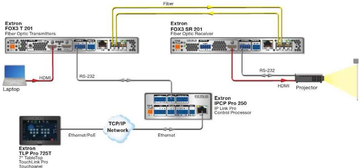
A user can connect a control system to send and receive RS-232 data over the fiber and the captive screw port of the transmitter and receiver.
Captive Screw Insertion
A user can connect an RS-232 signal from a control system to an endpoint and pass that signal over the fiber to the connected endpoint. An RS-232 signal must be inserted in the RS-232 port on the transmitter or receiver and bidirectional fiber must be used.
The RS-232 signal settings are:
• Baud rate: 9600 (default) to 115200
• Data bits: 5 to 8 (default)
- Stop bits: 1 (default) to 2
• Parity: Odd, Even, or None (default)
The RS-232 insertion method must be set to Captive Screw Insertion via PCS (see the FOX3 SR 201 Help File) on both endpoints passing the control signal.
Example of a bidirectional fiber system (see figure 11):
-
On the FOX3 transmitter and receiver, configure the RS-232 Insertion via PCS.
• The control system then sends a control command: -
Into the transmitter Control RS-232 port.
- Out of the transmitter SFP A port to the receiver SFP A IN port.
• To the receiver captive screw port. - Into the display to take some action.
- The response from the display is sent back to the control system.
flowchart
graph TD
    A["Extron FOX3 T 201\nFiber Optic Transmitters"] -->|HDMI| B["Laptop"]
    B -->|HDMI| C["Extron TLP Pro 725T\n7" TableTop\nTouchLink Pro\nTouchpanel"]
    C -->|Ethernet/PoE| D["TCP/IP Network"]
    D -->|Ethernet| E["Extron IPCP Pro 250\nIP Link Pro\nControl Processor"]
    E -->|RS-232| F["Projector"]
    F -->|HDMI| G["Extron FOX3 SR 201\nFiber Optic Receiver"]
    G -->|HDMI| H["Projector"]
    H -->|RS-232| I["Projector"]
    I --> J["Extron FOX3 SR 201\nFiber Optic Receiver"]
    J -->|HDMI| K["Projector"]
    K --> L["Extron FOX3 SR 201\nFiber Optic Receiver"]
    L -->|HDMI| M["Projector"]
    M --> N["Extron FOX3 SR 201\nFiber Optic Receiver"]
    N -->|HDMI| O["Projector"]
    O --> P["Extron FOX3 SR 201\nFiber Optic Receiver"]
    P -->|HDMI| Q["Projector"]
    Q --> R["Extron FOX3 SR 201\nFiber Optic Receiver"]
    R -->|HDMI| S["Projector"]
    S --> T["Extron FOX3 SR 201\nFiber Optic Receiver"]
    T -->|HDMI| U["Projector"]
    U --> V["Extron FOX3 SR 201\nFiber Optic Receiver"]
    V -->|HDMI| W["Projector"]
    W --> X["Extron FOX3 SR 201\nFiber Optic Receiver"]
    X -->|HDMI| Y["Projector"]
    Y --> Z["Extron FOX3 SR 201\nFiber Optic Receiver"]
    Z -->|HDMI| AA["Projector"]
    AA --> AB["Extron FOX3 SR 201\nFiber Optic Receiver"]
    AB -->|HDMI| AC["Projector"]
    AC --> AD["Extron FOX3 SR 201\nFiber Optic Receiver"]
    AD -->|HDMI| AE["Projector"]
    AE --> AF["Extron FOX3 SR 201\nFiber Optic Receiver"]
    AF --> AG["Projector"]
    AG --> AH["Extron FOX3 SR 201\nFiber Optic Receiver"]
    AH --> AI["Projector"]
    AI --> AJ["Extron FOX3 SR 201\nFiber Optic Receiver"]
    AJ --> AK["Projector"]
    AK --> AL["Extron FOX3 SR 201\nFiber Optic Receiver"]
    AL --> AM["Projector"]
    AM --> AN["Extron FOX3 SR 201\nFiber Optic Receiver"]
    AN --> AO["Projector"]
    AO --> AP["Extron FOX3 SR 201\nFiber Optic Receiver"]
    AP --> AQ["Projector"]
    AQ --> AR["Extron FOX3 SR 201\nFiber Optic Receiver"]
    AR --> AS["Projector"]
    AS --> AT["Extron FOX3 SR 201\nFiber Optic Receiver"]
    AT --> AU["Projector"]
    AU --> AV["Extron FOX3 SR 201\nFiber Optic Receiver"]
    AV --> AW["Projector"]
    AW --> AX["Extron FOX3 SR 201\nFiber Optic Receiver"]
    AX --> AY["Projector"]
    AY --> AZ["Extron FOX3 SR 201\nFiber Optic Receiver"]
    AZ --> BA["Projector"]
    BA --> BB["Extron FOX3 SR 201\nFiber Optic Receiver"]
    BB --> BC["Projector"]
    BC --> BD["Extron FOX3 SR 201\nFiber Optic Receiver"]
    BD --> BE["Projector"]
    BE --> BF["Extron FOX3 SR 201\nFiber Optic Receiver"]
    BF --> BG["Projector"]
    BG --> BH["Extron FOX3 SR 201\nFiber Optic Receiver"]
    BH --> BI["Projector"]
    BI --> BJ["Extron FOX3 SR 201\nFiber Optic Receiver"]
    BJ --> BK["Projector"]
    BK --> BL["Extron FOX3 SR 201\nFiber Optic Receiver"]
    BL --> BM["Projector"]
    BM --> BN["Extron FOX3 SR 201\nFiber Optic Receiver"]
    BN --> BO["Projector"]
    BO --> BP["Extron FOX3 SR 201\nFiber Optic Receiver"]
    BP --> BQ["Projector"]
    BQ --> BR["Extron FOX3 SR 201\nFiber Optic Receiver"]
    BR --> BS["Projector"]
    BS --> BT["Extron FOX3 SR 201\nFiber Optic Receiver"]
    BT --> BU["Projector"]
    BU --> BV["Extron FOX3 SR 201\nFiber Optic Receiver"]
    BV --> BW["Projector"]
    BW --> BX["Extron FOX3 SR 201\nFiber Optic Receiver"]
    BX --> BY["Projector"]
    BY --> BZ["Extron FOX3 SR 201\nFiber Optic Receiver"]
    BZ --> CA["Projector"]
    CA --> CB["Extron FOX3 SR 201\nFiber Optic Receiver"]
    CB --> CC["Projector"]
    CC --> CD["Extron FOX3 SR 201\nFiber Optic Receiver"]
    CD --> CE["Projector"]
    CE --> CF["Extron FOX3 SR 201\nFiber Optic Receiver"]
    CF --> CG["Projector"]
    CG --> CH["Extron FOX3 SR 201\nFiber Optic Receiver"]
    CH --> CI["Projector"]
    CI --> CJ["Extron FOX3 SR 201\nFiber Optic Receiver"]
    CJ --> CK["Projector"]
Figure 11. Typical Captive Screw Insertion Configuration
Audio Configuration
Audio Embedding
The FOX3 supports a single audio signal to pass LPCM-2CH. The audio input sent over the fiber output can be configured via PCS (see the FOX3 T 201 PCS Help File) or SIS command (see Input audio selection on page 25). Select digital, analog, or auto.
Audio Input Gain
Adjust the transmitter gain level for the analog audio input via PCS (see the FOX3 T 201 PCS Help File). The analog audio input can be adjusted from -18 dB to +24 dB in 1 dB steps.
Audio Input Configuration
Select the audio on the input of the transmitter via PCS (see the FOX3 T 201 PCS Help File) or SIS command (see Input audio selection).
The audio input options are:
- Auto (default) — The transmitter selects between digital and analog audio based on the digital audio input signal.
- Digital audio is selected when embedded audio is present on the HDMI input.
- Analog audio is selected when digital audio is not detected.
- Force Digital — Digital embedded audio is passed to the local HDMI and fiber output.
• Force Analog — Analog audio is passed to the local HDMI and fiber output.
Audio Mute
Mute audio on the Loop Out, HDMI output, and analog audio output individually via PCS (see the FOX3 T 201 PCS Help File) or SIS commands (see Audio mute — Digital Output or Analog Audio Out on page 22).
SIS Configuration and Control
This section describes the remote control operation of the FOX3 T 201 transmitter, including:
- Host Control Ports
• Simple Instruction Set Control
• Command and Response Table for SIS Commands
The FOX3 transmitter can be configured using SIS commands, PCS, or embedded web pages. The FOX3 transmitter can be controlled using SIS commands or PCS. Configure and control the FOX3 transmitter remotely via a host computer or other device (such as a control system) by connecting to the rear panel RS-232 port, LAN port, or the front panel USB port.
Host Control Ports
Rear Panel RS-232 Port
The rear panel serial port (see figure 2, G on page 5) can be connected to a host device such as a computer running Extron DataViewer, available at www.extron.com. The port makes serial control of the FOX3 device possible. Use the protocol information listed below to make the connection.
The protocol for the serial ports is as follows:
• 9600 baud
- no parity
- 8 data bits
- 1 stop bit - no flow control
Front Panel Configuration USB Port
The front panel mini B USB Configuration port (see figure 9, B on page 12) can be connected to a host computer for configuration using SIS commands via an SSH client and IP address 203.0.113.22 on port 22023.
Ethernet (LAN) Ports
The rear panel Ethernet connector (see figure 2 on page 5) can be connected to an Ethernet LAN or WAN. Communications between the transmitter and the controlling device is via an SSH client, using port 22023. This connection makes SIS control of the unit possible using a computer connected to the same LAN or WAN (see TP Cable Termination and Recommendations on page 11 to wire the LAN connector).
Default IP address
To access the FOX3 transmitter via the LAN port, the IP address, subnet mask, and the gateway address for the devices are needed. If the addresses have not been changed, the factory-specified defaults are:
• IP address 192.168.254.254
• Gateway address 0.0.0.0
- Subnet mask 255.255.255.0
Establishing a Connection
Establish a network connection to a FOX3 device as follows:
- Download the SSH client software from the internet.
- Open the SSH client software.
- Enter the IP address of the FOX3 device in the Host Name or IP address field.
NOTE: If the local system administrators have not changed the value, the default IP address is 192.168.254.254.
-
Enter 22023 in the Port field.
-
The FOX3 device is password protected, so the appropriate administrator or user name and password must be entered.
-
If the login and password are correct, the device responds with a copyright message including the copyright year, the name of the product, firmware version, part number, and the current date and time.
- If the login and password are incorrect, the Login as prompt returns. Enter the administrator or user name and password again.
NOTES:
- The FOX3 device is shipped password-protected. The factory configured passwords for all accounts on this device have been set to the device serial number.
- In the event of a complete system reset, the password converts to the default, which is extron. New passwords must be configured to secure the device.
- On password-protected connections, there are two levels of protection: administrator and user. Administrators have full access to all editing functions.
Using verbose mode
SSH connections to a FOX3 device can be used to monitor for changes that occur on the device, such as SIS commands from other SSH sockets or a serial port. For an SSH session to receive change notices from the device, the SSH session must be in verbose mode 1 or 3 (see the SIS command Verbose mode on page 23).
Simple Instruction Set Control
Host-to-Unit Instructions
SIS commands consist of one or more characters per field. No special characters are required to begin or end a command character sequence. When a command is valid, the transmitter executes the command and sends a response to the host device. All responses from the transmitter to the host end with a carriage return and a line feed (CR/LF = ←), which signals the end of the response character string. A string is one or more characters.
Device-Initiated Power-Up Message
When the device completes its start-up, it issues the following message to the host:
© Copyright 20yy, Extron FOX3 T 201 MM (SM), Vx.xx, 60-nnnn-nn
• 20yy is the copyright year
- Vx.xx is the firmware version number
• 60-nnnn-nn is the part number.
NOTE: This message only displays if the FOX3 device is connected to the serial port.
Error Responses
When the transmitter receives a valid SIS command, it executes the command and sends a response to the host device. If the transmitter is unable to execute the command because the command is invalid or it contains invalid parameters, the transmitter returns an error response to the host. The error response codes are:
• E10 — Invalid command
• E21 — Invalid room number
• E11 — Invalid preset number
E22 — Busy
• E13 — Invalid parameter
• E24 — Privilege violation
• E14 — Invalid for this configuration
• E25 — Device not present
• E17 — Invalid command for signal type
• E26 — Maximum number of connections exceeded
• E18 — System or command timed out
• E28 — Bad file name or file not found
Timeout
Pauses of 10 seconds or longer between command ASCII characters result in a timeout. The command operation is aborted with no other indication.
Using the Command and Response Table
The command and response table begins below. Symbols are used throughout the table to represent variables in the command and response fields. Command and response examples are shown throughout the table. The ASCII to HEX conversion table below is for use with the command and response table.
| ASCII to | Hex | Conversion Table | Esc | 1B | CR | ∅D | LF | ∅A | |||||||
| Space → | 20 | ! | 21 | “ | 22 | # | 23 | $ | 24 | % | 25 | & | 26 | ‘ | 27 |
| (28) | ) | 29 | * | 2A | + | 2B | , | 2C | - | 2D | . | 2E | / | 2F | |
| ∅ | 30 | 1 | 31 | 2 | 32 | 3 | 33 | 4 | 34 | 5 | 35 | 6 | 36 | 7 | |
| 8 | 38 | 9 | 39 | : | 3A | ; | 3B | < | 3C | = | 3D | > | 3E | ? | |
| @ | 40 | A | 41 | B | 42 | C | 43 | D | 44 | E | 45 | F | 46 | G | |
| H | 48 | | | 49 | J | 4A | K | 4B | L | 4C | M | 4D | N | 4E | O | |
| P | 50 | Q | 51 | R | 52 | S | 53 | T | 54 | U | 55 | V | 56 | W | |
| X | 58 | Y | 59 | Z | 5A | [ | 5B | \ | 5C] | 5D | ^ | 5E | _ | 5F | |
| ` | 60 | a | 61 | b | 62 | c | 63 | d | 64 | e | 65 | f | 66 | g | |
| h | 68 | i | 69 | j | 6A | k | 6B | l | 6C | m | 6D | n | 6E | o | |
| p | 70 | q | 71 | r | 72 | s | 73 | t | 74 | u | 75 | v | 76 | w | |
| x | 78 | y | 79 | z | 7A | { | 7B | | | 7C} | 7D | ~ | 7E | DEL | 7F | |
NOTE: For commands and examples of computer or device responses used in this guide, the character “θ” is the number zero and “O” is the capital letter “o.”
Common symbol definitions
← = Carriage return/line feed
- = Space
← or | = Carriage return (no line feed)
Esc or W = Escape key
x1 = Video mute θ = Unmute (default) 1 = Mute video only
2 = Mute video and sync
[X2] = Audio output 1 = Digital (Tx Loop Out)
3 = All outputs
X3 = Audio mute status = Unmute (default), 1 = Mute
X4 = Input video signal status 0 = Not detected, 1 = Detected
5 = Input audio status = Not detected, 1 = Detected
x6 = Input HDCP status θ = No source detected
1 = Source with HDCP detected (default)
2 = Source with no HDCP present
7 = Output HDCP status = No active sink detected
1 = Sink detected, output signal encrypted
2 = Sink detected, output signal not encrypted
= Auto 1 = Digital 2 = Analog
TX or RX
x8 = Input audio selected
θ = Off (default) 1 = On
X9 = Device type
X10 = Enable DHCP
X11 = IP address, subnet, gateway address
XXX.XXX.XXX.XXX
X12 = Baud rate 300 - 115200 baud (9600 default)
X13 = Parity odd, even, none (default), mark, space
(only the first letter required)
x14 = Data bits 7, 8 (default)
X15 = Stop bits 1 (default), 2
X16 = UARTs 1 = Endpoint
X17 = Verbose mode θ = Clear/none (default for Ethernet)
1 = Verbose mode (default for RS-232)
2 = Tagged response for queries
3 = Verbose mode and tagged responses for queries
X18 = Active fiber link 1 = SFP A 2 = SFP B
X19 = Input HDCP Authorization = HDCP authorized off 1 = HDCP authorized on (default)
20 = Resolution and refresh rate nnnnHorizontalxnnnnnVertical@xxHz (example: 3840x2160@59.9Hz) (0000x0000@000Hz = no input detected)
X21 = Detected audio input format = Not detected 1 = Digital 2 = Analog
X22 = Detected Video input color space format θ = Not detected 1 = YUV 2 = RGB
X23 = Detected pixel clock 4-digit response with 0 padding (example: 297 = 0297MHZ) (0000 = No pixel clock detected)
X28 = Fiber link detection = Not Detected 2 = Detected
X29 = Fiber optic mode SM or MM
X30 = Enable or Disable Echo = Disabled 2 = Enabled (default)
[X31] = Timeout The number of seconds before timeout on IP connections (min=1, max=65000, with each number equivalent to 10 seconds [default=30=300 seconds])
32 = Force 4K60 compressed mode = Disable (default; after a reset, setting defaults back to ) 1 = Force 4K60 on 1 fiber
X33 = View audio output 1 = Digital 2 = Analog
X34 = Enable Telnet port 23 θ = Off (default) 23 = Telnet port 23 enabled
X35 = Port number Response is 5 digits with leading zeros, for example 00000 or 00023
Command and Response Table for SIS Commands
| Command Function | SIS Command (Host to Unit) | Response (Unit to Host) | Additional description |
| Video mute | |||
| Mute output video only | 1B | Vmt1← | |
| Mute output video and sync | 2B | Vmt2← | |
| Unmute video and sync | 0B | Vmt0← | Default |
| View mute status | B | X1← | |
| Verbose mode 2/3: | Vmt[X1]← | ||
| KEY: X1= Video mute | 0 = Unmute (default) | 1 = Mute video only | 2 = Mute video and sync |
| Audio mute - Digital Output or Analog Audio Out | |||
| Enable Audio mute | X2*1Z Amt | X2*1← | |
| Example: | 1*1Z | Amt1*1← | Digital audio (embedded on HDMI output) is muted. |
| Disable audio mute | X2*0Z Amt | X2*0← | |
| Example: | 3*0Z | Amt3*0← | Default. All audio is unmuted. |
| View audio mute status | X33Z | X3← | |
| NOTE: To view audio mute status, digital audio status and analog audio status must be viewed individually. | |||
| KEY: X2= Audio output | 1 = Digital out (Tx Loop Out), | 3 = All outputs (digital and analog) | |
| X3= Audio mute status | 0 = Unmute (default) | 1 = Mute | |
| X33= View audio output | 1 = Digital | 2 = Analog | |
| Information requests | |||
| View firmware version | Q/q | x.xx← | |
| Verbose mode 2/3: | Ver 01*x.xx← | ||
| View full firmware version | *Q/q | x.xx.xxxx← | |
| Verbose mode 2/3: | Bld x.xx.xxxx← | ||
| View part number | N/n | 60-xxxx-xx← | |
| Verbose mode 2/3: | Pno 60-xxxx-xx← | ||
| View Extron serial number | 19I/i | Serial number← | |
| Verbose mode 2/3: | Inf19*Serial number← | ||
| View updated FPGA version | 35Q/q | x.xx← | |
| Verbose mode 2/3: | Ver 35*x.xx← | ||
| View input video status | 4S/s | X4← | |
| Verbose mode 2/3: | Sts04*X4← | ||
| View input audio status | 5S/s | X5← | |
| Verbose mode 2/3: | Sts05*X5← | ||
| View input HDCP status | Esc IHDCP← | X6← | |
| Verbose mode 2/3: | HdcpIX6← | ||
| View output HDCP status | Esc OHDCP← | X7← | |
| Verbose mode 2/3: | HdcpOX7← | ||
| NOTE: If a non-HDCP compliant display is connected, the HDCPO response is always 2. | |||
| KEY: X4= Input video signal status | 0 = Not detected | 1 = Detected | |
| X5= Input audio status | 0 = Not detected | 1 = Detected | |
| X6= Input HDCP status | 0 = No source detected | 1 = Source with HDCP detected (default) | |
| 2 = Source with no HDCP present | |||
| X7= Output HDCP status | 0 = No active sink detected | 1 = Sink detected, output signal encrypted | |
| 2 = Sink detected, output signal not encrypted | |||
| Information requests (continued) | |||
| Information request | I SFPALnk | X28•SFPBLnkX28•SigTX4•HdcpTX6•HdcpCX7•AudTX8•X9•X29← | |
| Verbose mode 2/3: | Inf00*SFPALnk | X28•SFPBLnkX28•SigTX4•HdcpTX6•HdcpCX7•AudTX8•X9•X29← | |
| Response description: | |||
| Example: | Fiber link A•Fiber link B•Signal input•Input HDCP•Output HDCP•Input audio•Transmitter•Fiber mode← | ||
| I | SFPALnk1•SFPBLnk1•SigI1•HdcpI1•HdcpO1•AudI1•TX•SM← | ||
| Signals are detected on the two fiber links, a signal is detected on the input, the input and output are HDCP devices, the digital audio input is selected, the device is a transmitter, and the fiber mode is singlemode. | |||
| KEY: | X4= Input video signal status | θ = Not detected | 1 = Detected |
| X6= Input HDCP status | θ = No source detected | 1 = Source with HDCP detected (default) | |
| 2 = Source with no HDCP present | |||
| X7= Output HDCP status | θ = No active sink detected | 1 = Sink detected, output signal encrypted | |
| 2 = Sink detected, output signal not encrypted | |||
| X8= Input audio selection | θ = Auto | 1 = Digital 2 = Analog | |
| X9= Device type | TX or RX | ||
| X28= Fiber link detection | θ = Not detected | 1 = Detected | |
| X29= Fiber optic mode | SM or MM | ||
| View LinkLicense | EscLELIC← | FOX3 Uncompressed Video, 79-2560-01←If LinkLicense is not installed, returns← | |
| DHCP client | |||
| Set DHCP on or off | EscX10DH← | IdhX10← | |
| View DHCP status | EscDH← | X10← | |
| KEY: | X10= Set DHCP | θ = Off (default) | 1 = On |
| Telnet port | |||
| Set Telnet port map | EscZX34PMAP← | PmapZX35← | Sets Telnet port map to X34. |
| View Telnet port map | EscZPMAP← | X35← | |
| KEY: | X34= Enable Telnet port 23 | θ = Off (default) | 23 = Telnet port 23 enabled |
| X35= Port number | Response is 5 digits with leading zeros, for example 00000 or 00023 | ||
| Echo for SIS over SSH (port 22023) | |||
| Enable Echo | Esc1ECHO← | Echo1← | Returns command entered with response. |
| Disable Echo | Esc0ECHO← | Echo0← | Returns response only. |
| View Echo status | EscECHO← | X30← | |
| NOTE: This command is only applicable to the SIS over SSH connection using the LAN or USB ports. The echo setting is for the current connection only, and remains until the connection is closed. Apply after connection is established. | |||
| KEY: | X30= Enable or disable Echo | θ = Disable | 1 = Enable (default) |
| Verbose mode | |||
| Set verbose mode | EscX17CV← | VrbX17← | |
| View verbose mode | EscCV← | X17← | |
| NOTE: Verbose mode reverts back to default in the event of a power cycle, disconnect from dataviewer, or disconnect from the Ethernet. | |||
| KEY: | X17= Verbose mode | θ = Clear/none (default for Ethernet) | 1 = Verbose mode (default for RS-232) |
| 2 = Tagged response for queries | 3 = Verbose mode and tagged responses for queries | ||
| Timeout Ethernet data port | |||
| Set current port timeout | Esc 0*X31TC← | Pti0*X31← | |
| View current port timeout | Esc 0TC← X31← | ||
| KEY: X31 = Timeout | The number of seconds before timeout on IP connections (min=1, max=65000, with each number equivalent to 10 seconds [default=30=300 seconds]) | ||
| IP address | |||
| Set IP address | Esc X11CI← | Ipi•X11← | |
| View IP address | Esc CI← X11← | ||
| KEY: X11 = IP address | xxx.xxx.xxx.xxx | ||
| RS-232 COMM settings | |||
| Set serial port parameters | Esc X16 *X12, X13, X14, X15CP← Cpn X16 • Ccp X12, X13, X14, X15← | ||
| KEY: X12 = Baud rate 300 - 115200 baud (9600 default)X13 = Parity odd, even, none (default), mark, space (only the first letter required)X14 = Data bits 7, 8 (default)X15 = Stop bits 1 (default), 2X16 = UARTs 1 = endpoint (this is the default for the device) | |||
| Resets | |||
| Erase all files from flash memory | Esc ZFFF← | Zpf← | Removes files created in user space. |
| Reset unit settings | Esc ZXXX← | Zpx← | Resets unit to factory default, excludes IP settings. |
| Absolute system reset (retain IP) | Esc ZY← | Zpy← | Same as Esc ZQQQ except excludes IP settings. |
| Absolute system reset | Esc ZQQQ← | Zpq← | Master Reset resets all settings to factory default. |
| IP system reset | Esc 1ZQQQ← | Zpq1← | Resets only IP settings. |
| Reset audio gain and attenuation | Esc ZA← | Zpa← | Reset audio gain & attenuation to default levels. |
| Global unsolicited response | |||
| Input change | Reconfig← | Any change of the input frequency, during module install, or a power cycle. | |
| Fiber link | Sts02*X18*X28← | Any change in fiber link status. | |
| Input video signal presence | SigT X4← | Any change in input signal status. | |
| Input HDCP | HdcpI X6← | Any change in input HDCP status. | |
| Output HDCP | HdcpO X7← | Any change in output HDCP status. | |
| Audio input status | Sts05*X5← | Displays input audio status. | |
| KEY: X4 = Input video signal status 0 = Not detected 1 = DetectedX5 = Input audio status 0 = Not detected 1 = DetectedX6 = Input HDCP status 0 = No source detected 1 = Source with HDCP detectedX7 = Output HDCP status 2 = Source with no HDCP present0 = No active sink detected 1 = Sink detected, output signal encrypted2 = Sink detected, output signal not encryptedX18 = Active fiber link 1 = SFP A 2 = SFP BX28 = Fiber Link detection (SPF A/B IN LED) 0 = Not detected 1 = DetectedNOTE: SFP A and SFP B OUT LED is always activeHDCP authorized device | |||
| Set HDCP authorized device on | Esc E1HDCP← | HdcpE1← | |
| Set HDCP authorized device off | Esc E0HDCP← | HdcpE0← | |
| View HDCP authorized device | Esc EHDCP← | X19← | Default: HDCP authorized on. |
| Verbose mode 2/3: | HdcpE X19← | ||
| KEY: X19 = Input HDCP Authorization θ = HDCP authorized off 1 = HDCP authorized on (default) | |||
| Input audio selection | |||
| Select audio input | Esc I X8 AFMT← Afmt I X8← | Default. Digital has priority. | |
| View selected audio input | Esc IAFMT← X8← | ||
| KEY: X8 = Input audio selection θ = Auto (default) 1 = Digital 2 = Analog | |||
| Input signal detection information | |||
| View detected input signal information | 35I/i | Res X20 • Aud I X21 • Vcs I X22 • Pixcl X23← | |
| Verbose mode 2/3: | Inf35*Res X20 • Aud I X21 • Vcs I X22 • Pixcl X23← | ||
| KEY: X19 = Input HDCP Authorization θ = HDCP authorized off 1 = HDCP authorized on (default) | |||
| X20 = Resolution and refresh rate nnnn Horizontal xnnnn Vertical @xxHz (0000x0000@000Hz = no input detected) | |||
| X21 = Detected input audio format θ = Not detected 1 = Digital 2 = Analog | |||
| X22 = Detected video input color space θ = Not detected 1 = YUV 2 = RGB | |||
| X23 = Pixel clock (in MHz) 4-digit response with θ padding (example: 294 = 0294MHZ) (0000 = Not detected) | |||
| Force 4K60 compressed mode | |||
| Force 4K 60 compressed mode | Esc C1 FOXM← | FoxmC1← | Sends 4K60 signal compressed on 1 fiber |
| Disable 4K 60 compressed mode | Esc C0 FOXM← | FoxmC0← | Sends 4K60 signal uncompressed on 2 fibers |
| View 4K 60 compressed mode status | Esc CFOXM← | X24← | |
| Verbose mode 2/3 | FoxmC X24← | ||
| NOTE: This command only applies to devices with the 4K60 Uncompressed Video LinkLicense or transmitter units with part numbers ending with -13 or -14. If the command is issued to the wrong unit, return E14. | |||
| KEY: X24 = Force 4K60 compressed mode θ = Disable (default; after a reset, setting defaults back to θ) 1 = Force 4K60 on 1 fiber | |||
Configuration Software
The FOX3 201 transmitter can be easily configured using Extron Product Configuration Software (PCS). This section describes the software installation and communication (see the FOX3 T 201 PCS Help File for detailed control information). The topics covered in this section are:
• Software/Firmware Installation
- Connecting to PCS
- Software Overview
Software/Firmware Installation
Visit www.extron.com to download and install the PCS software.
NOTES:
- Also download the latest versions of software and firmware for your product.
- An Extron Insider account is required to download either firmware or software.
-
Software and firmware can also be downloaded from the Download tab on the product web page.
-
Mouse over the Download link at the top of the page (see figure 12, ①).

Figure 12. Software Links on Download Screen
- Click the appropriate link on the drop-down list.
For software, either click the Software link (2) or, if the software is listed, click directly on that link (see the PCS Product Configuration Software link (3)) and skip to step 5 on page 27.
For firmware, click the Firmware link (4).
-
If there is no direct link to your software, click the Software link (②).
-
Scroll down to the alphabetic navigation bar (see figure 13).
| ALL | # | A | B | C | D | E | F | G | H | I | J | K | L | M | N | O | P | Q | R | S | T | U | V | W | X | Y | Z |
Figure 13. Software Installation
- Click the appropriate letter to locate the software or firmware.
- Click Download and follow the on-screen instructions (see figure 14, ① for PCS).
| Version | Release Date | New in the Current Release | Size | |
| 4.3.0 | Jul. 9, 2018 | Added support for HC 403Added language support for Spanish, Simplified Chinese, Japanese, German, and FrenchAbility to restore configuration to multiple devices across all IN1608 products | 162.5 MBDownloadLogin required | |
Figure 14. PCS Software Download
For Firmware:

Figure 15. Firmware Page with Alphabetic Navigation Bar
a. Click the letter F from the alphabetic navigation bar (see figure 15, ①).
b. Scroll down the page to find the firmware for the FOX3 T 201.
c. (Optional) Click Release Notes (②) for more information about the firmware update.
d. Click Download (③). The product download screen opens.
e. Enter the required user information and click Download. An executable (.exe) file is downloaded to the PC. Run this program to place the firmware on the PC for future use. Make a note of the folder where the firmware file was saved.
- Install the software.
a. Navigate to the folder where the software file was downloaded.
b. Double-click the executable file and follow the on-screen directions to install the software.
For Firmware:
a. To install via PCS, see Update Firmware in the Device Menu on page 33.
b. To install via the internal web pages, see the Firmware Panel on page 38.
Connecting to PCS
The Extron Product Configuration Software window opens with the Device Discovery panel open. Connect to the device using the Device Discovery panel or the TCP/IP panel (see figure 16).
Device Discovery Panel
The Device Discovery panel displays accessible Extron devices connected directly to the PC or to a LAN or WAN. Devices are identified and sorted by model, IP address, device name, or connection method.
- Open the Product Configuration Software program from the desktop shortcut. The Extron PCS window opens to the Device Discovery panel (see figure 16).

Figure 16. Device Discovery Panel
- Select the FOX3 T 201 device by clicking on it to highlight it in the list (①).
- Click Connect (②).
To edit the IP address:
- Click on the Edit button (③). The Communication Settings box pens.
- Click in the field to edit the address (see figure 17).
- Click Apply to complete and close. Alternatively, click Apply and Connect to complete and connect to the device.
Click Cancel to close the box without changes.

Figure 17. Communication Settings Box
TCP/IP Panel
The TCP/IP panel connects PCS to a specific device through Ethernet or USB over IP.

Figure 18. Comm Port Selection Windows
- Click the TCP/IP tab (see figure 18, ①).
- In the IP Address/Hostname field (②), enter the IP address of the desired device.
NOTE: If the IP address has not been changed, it is 192.168.254.254 for the LAN port or 203.0.113.22 for the front panel USB port.
- In the Password field (③), enter the device password.
NOTE: The factory configured passwords for all accounts on this device have been set to the device serial number. In the event of a complete system reset, the passwords convert to the default, which is extron (see Roles and Permissions Panel on page 39 to change a password).
- Leave the Port field (④) empty. The device searches for the port to connect.
NOTE: Select the Show Characters checkbox (⑤) to display the password characters.
- Click the Connect button (⑥). A new device tab opens.
Offline Device Preview
Opening a new device tab for an offline device displays the interface and configuration options for the device without connecting to it. However, settings cannot be changed.
NOTE: This is a view only mode. The FOX3 cannot be configured in this view.
To open a scaler device tab:
- From the Configuration File drop-down list, select New Configuration File (see figure 19).

Figure 19. Configuration File Drop-Down List
The New Configuration File dialog box opens (see figure 20).

Figure 20. New Configuration File Dialog Box
- Select the desired device model from the Device Models list.
- Click the Configure button. A new offline device configuration tab opens.
Software Overview
NOTE: For details about specific software features, see the FOX3 T 201 PCS Help File.

Figure 21. FOX3 T 201 Main Window
Each PCS screen has a Device drop-down list (see figure 21, ①) for device configuration options. The Software menu (②) contains software configuration and information options.
Software Menu
The Software menu (see figure 22) contains options pertaining to PCS settings.
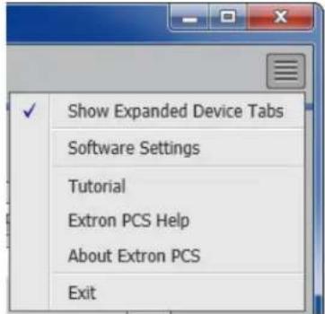
Figure 22. PCS Software Menu
Show Expanded Device Tabs
Selecting Show Expanded Device Tabs from the Software menu displays the device IP address or connection method in the Device tab.

Figure 23. Expanded Device Tab
Software Settings
This option resets all disabled confirmation dialogs to the default settings.
- From the Software menu, select Software Settings. The Software Settings dialog box opens.

Figure 24. Software Settings Dialog Box
- Click the Re-enable Confirmation Dialogs button (see figure 24, 1). The dialog box closes and the reset is complete.
Alternatively, click the Close button (②) to close the dialog box without re-enabling the confirmation dialogs.
Tutorial
Display a general overview of where to find features in the PCS framework.
-
From the Software menu, select Tutorial. The Tutorial dialog box opens.
-
Click the OK button to close the dialog box.
Extron PCS Help
Open the PCS help file for general PCS operations.
From the Software menu, select Extron PCS Help.
About Extron PCS
Display information about the current PCS version.
- From the Software menu, select About Extron PCS. The About - Extron PCS dialog box opens.

Figure 25. About - Extron PCS Dialog Box
- Click the Details button (see figure 25, ①) for more information.
- To display details about third-party software packages and associated licensing, click Licenses (②).
- Click the OK button (③) to close the dialog box.
Exit
Disconnect connected devices and close the application.
- From the Software menu, select Exit. If device tabs are open, the Exit dialog box opens (see figure 26).

Figure 26. Exit Dialog Box
- Click the Close Session(s) and Exit button (1) to disconnect the software from connected devices, close all offline device tabs, and close the software.
Alternatively, click the Cancel button (②) to leave the software open.
Device Menu
The Device menu contains options pertaining to device connection, configuration, and information. For details about all these options, see the FOX3 T 201 PCS Help File.

Figure 27. Device Menu
- Disconnect — Disconnect the device from the PCS program and close the Device tab.
- Settings — Open a submenu with the following options:
- Hardware Settings — Display the Hardware Settings dialog box with device information and side tabs to change the device name, internal clock, and password of the connected device.
It also contains an Edit Communication Settings button, which provides an alternative method of accessing the Communication Settings dialog box.
- Communication Settings — Open the Communication Settings dialog box to change IP settings of the connected device.
- Reset Device — Open the Reset Device dialog box, with selectable modes for resetting the connected device, as well as the Unit Information (also displayed in the Hardware Settings dialog box).
NOTE: The factory configured passwords for all accounts on this device have been set to the device serial number. In the event of a complete system reset, the passwords convert to the default, which is extron (see Roles and Permissions Panel on page 39 to change a password).
- Backup — Export all audio, video, and communication settings of the connected device to the PC. This exported configuration can be saved as a backup file (with a .extz extension), or used to replicate settings from one device to other devices of the same model. When restoring a configuration, select specific device settings.
-
Restore — Open a submenu containing restore options:
-
Restore this Device — Upload a saved configuration for a FOX3 T 201 to the connected device.
- Restore to Multiple Devices — Upload a saved configuration file for an FOX3 T 201 to multiple devices on the network.
NOTE: The connected devices must be connected via LAN.
- Update Firmware — Open a submenu to upload firmware from the host device to the connected device or to multiple devices.
NOTE: If necessary, download new firmware from the Extron website (see Software/Firmware Installation on page 26).
- Update Firmware to this Device... — Upload firmware from the host device to the connected device only.
- Update Firmware to Multiple Devices... — Upload firmware to multiple devices on the network.
NOTE: The connected devices must be connected via LAN.
- FOX3 T 201 MM (60-1600-13) Help — Open the FOX3 T 201 PCS Help File in a separate window.
- About This Module — Open the About This Module dialog box, with the module part number and firmware version of the connected device.
Internal Web Page
The FOX3 201 transmitter features an internal web server, displayed as a web page. Monitor and adjust certain settings of the FOX3 201 device via a LAN or WAN connection. Use a web browser to view the pages on a PC connected to the device LAN port or front panel USB port.
This section gives an overview of the internal web page, which is always available and cannot be erased or overwritten. Topics in this section include:
- Accessing the Internal Web Page
- Web Page Panels
Accessing the Internal Web Page
Access the FOX3 transmitter internal web page as follows:
- Connect the FOX3 device to a LAN or WAN using the rear panel RJ-45 LAN port or the front panel USB port (see figure 2 on page 5 or figure 9 on page 12).
- Open a web browser on a PC connected on the same LAN or WAN or connected to the front panel USB port.
NOTE: Compatible web browsers are Microsoft ^® Edge ^® , Modzilla ^® Firefox ^® , Google Chrome ^™ , and Apple ^® Safari ^® .
- Enter the FOX3 transmitter IP address in the browser Address field.
NOTE: If the IP address has not been changed, it is 192.168.254.254 for the LAN port or 203.0.113.22 for the front panel USB port.
- Press the
key on the keyboard. The web page password page opens.

Figure 28. Network Password Prompt
- The FOX3 is password protected. Enter a user name entry (user or admin) in the Username field and the password in the Password field when prompted (see figure 28).
NOTE: The factory configured passwords for all accounts on this device have been set to the device serial number. In the event of a complete system reset, the passwords convert to the default, which is extron.
- Click the Sign in button, if the unit is password protected.
Web Page Panels
The FOX3 T 201 internal web page (see figure 29) provides an overall, read-only view of the status of the transmitter, with some editable fields. Panels are:
① Device Info Panel
4 Firmware Panel
② Device Status Panel
⑤ Roles and Permissions Panel
③ Network Settings Panel
6 LinkLicense Panel
The panels that can be edited have an EDIT link to click to access the panel. To view general information about the FOX3 T 201, click the ABOUT link (⑦ About the FOX3 T 201).

Figure 29. FOX3 T 201 Internal Web Page
The internal web page does not automatically update. To see an updated page, click the Refresh button on the web browser.
Device Info Panel
The Device Info panel (see figure 29, ①) displays the device name, a brief product description, and the part number. The panel also contains an Extron link, which opens the Extron website in a new window.
To change the name:
- Click EDIT (see figure 30 [left], Ⓞ) in the Device Info panel. The Device Info Settings panel opens to allow edits (right).


Figure 30. Device Info Panel
- Edit the Device Name as desired.
- When finished editing, click SAVE to confirm your changes or CANCEL to close the window without making changes. Clicking the X in the upper-right corner of the screen also closes the window.
Device Status Panel
The Device Status panel (see figure 29, ② on page 36) displays the current date, time, time zone, the amount of time the device has been running (Uptime), and the internal temperature in degrees Celsius.
To set the date and time:
- Click EDIT (see figure 31 [left], ①) in the Device Status panel. The Device Status Settings panel opens to allow edits (right).
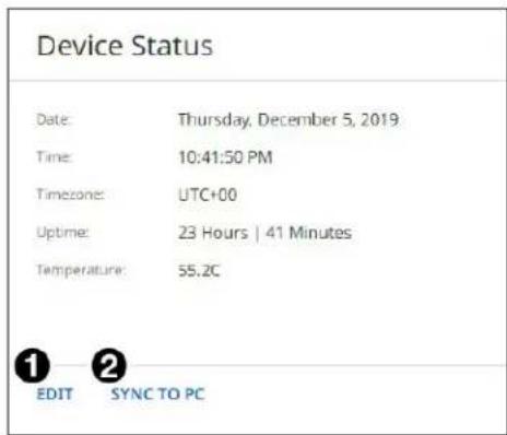
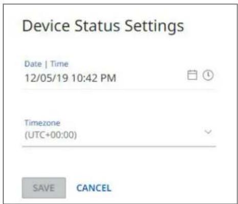
Figure 31. Device Status Panel
- Edit the Date/Time and Timezone as desired.
- When finished editing, click SAVE to confirm your changes or CANCEL to close the window without making changes. Clicking the X in the upper-right corner of the screen also closes the window.
- Alternatively, click SYNC TO PC (②) to set the date and time according to your PC.
Network Settings Panel
In the Network Settings panel (see figure 29, ③ on page 36), set the IP address, subnet mask, and gateway address for your FOX3, and turn DHCP On and Off.
To set the IP addresses:
- Click EDIT (see figure 32 [left], ①) in the Network Settings panel. The Network Settings panel opens to allow edits (right).

Figure 32. Network Settings Panel
- Edit the network settings as desired:
a. Click the DHCP switch (②) to toggle DHCP on and off. When DHCP is enabled (On), the unit configures its IP address and other network settings from the DHCP server. The default is Off.
b. To set any of the addresses (IP Address ③), Subnet mask ④, and Gateway address ⑤), click in the desired field and enter the address.
- When finished editing, click out of the field and click SAVE to confirm your changes or CANCEL to close the window without making changes. Clicking the X in the upper-right corner of the screen also closes the window.
Firmware Panel
The Firmware panel (see figure 29, 4) displays the current firmware version and the date it was last updated. Update the firmware on the FOX3 T 201 from this panel (see Software/Firmware Installation on page 26 to download the firmware files).
To update firmware:
- In the Firmware panel, click the SELECT FILE button.
- In the Open dialog box, browse to locate the new firmware file on your computer (by default the file is stored at C:\Program Files (x86)\Extron\Firmware\FOX3 T 201 after being downloaded from www.extron.com).
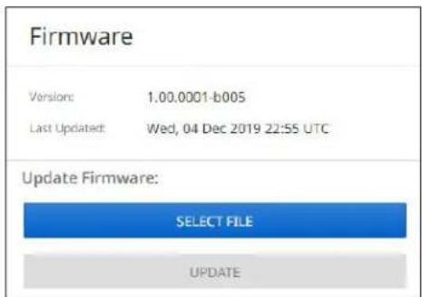
Figure 33. Firmware Panel
NOTE: Firmware files for FOX3 T 201 have a .eff extension. Do not attempt to load any other file types.
-
Double-click the firmware file name. The Open window closes, and the selected firmware file name appears in the Update Firmware panel on the web page.
-
Click UPDATE to begin (see figure 34). To cancel the update, click the X button in the Update Firmware panel.
During the updating process, a window appears in the middle of the screen,

Figure 34. Firmware Update Dialog Box
showing messages giving the progress of the update: Initializing, Installing the Firmware, and Rebooting Device.
When the update is completed, the message window closes and the message Firmware Upload Complete appears near the top of the screen. The new firmware filename appears beside Version in the Firmware panel.
Roles and Permissions Panel
The Roles and Permissions panel (see figure 29, 5, on page 36) displays whether Admin and User passwords have been set. It does not display the actual password.
NOTE: The following rules apply to passwords:
• Length is 1-128 characters.
- All human-readable characters are permitted except |.
• The password cannot be a single space.
- Passwords are case-sensitive.
- If the Admin password is cleared, the user password is cleared as well.
- The factory configured passwords for all accounts on this device have been set to the device serial number. In the event of a complete system reset, the passwords convert to the default, which is extron.
To assign administrator and user passwords:
-
In the Roles and Permissions panel, click EDIT (see figure 35). The Role and Permission Settings dialog box opens.
-
In the Admin panel, click the Change Admin Password link and enter the new administrator password in the field below (see figure 36 on page 40).
-
Click in the Confirm Admin Password field and enter the password from the Change Admin Password field.
-
To assign a user password, repeat steps 2 and 3 in the User panel.

Figure 35. Roles and Permissions Panel
- When finished, click SAVE to set the passwords. To close the window without saving a password, click CANCEL or the X in the upper-right corner.
NOTE: Passwords can be changed but they cannot be removed entirely. The FOX3 must have passwords at all times. These fields cannot be blank.

Figure 36. Passwords Dialog Box
LinkLicense Panel
The LinkLicense panel (see figure 29, 6 on page 36) displays information about any LinkLicense applied to the FOX3 device (A LinkLicense can be uploaded using the Extron Toolbelt software. See Software/Firmware Installation on page 26 to download the software).
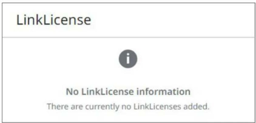
Figure 37. LinkLicense Panel
About the FOX3 T 201
Click on the ABOUT link (see figure 29, ⑦ on page 36) to open the About dialog box to view general information about the FOX3 T 201, such as the firmware version, copyright, part number, licenses, patents and web page version. Click on the View the End User License Agreement link to view the user license.

Figure 38. About the FOX3 T 201 Dialog Box
Equipment Mounting
This section provides procedures for mounting the FOX3 T 201 transmitter.
Mounting the Transmitter
ATTENTION:
The 1-inch high, half rack width transmitter can be placed on a table, mounted in a rack, or mounted under a desk or table. The transmitter can also be mounted on a projector bracket.
Tabletop Use
Affix the included rubber feet to the bottom of the unit and place it in any convenient location.
Mounting kits
Mount the unit using any optional compatible mounting kit listed on the Extron website (www.extron.com), in accordance with the directions included with the kit. For rack mounting, see UL Rack-Mounting Guidelines below.
UL Rack-Mounting Guidelines
The following Underwriters Laboratories (UL) requirements pertain to the installation of the FOX3 T 201 into a rack.
CAUTION:
- Elevated operating ambient temperature — If installed in a closed or multi-unit rack assembly, the operating ambient temperature of the rack environment may be greater than room ambient. Therefore, consider installing the equipment in an environment compatible with the maximum ambient temperature (TMA = +122°F, +50°C) specified by Extron.
- Reduced air flow — Installation of the equipment in a rack should be such that the amount of air flow required for safe operation of the equipment is not compromised.
- Mechanical loading — Mounting of the equipment in the rack should be such that a hazardous condition is not achieved due to uneven mechanical loading.
- Circuit overloading — Consideration should be given to the connection of the equipment to the supply circuit and the effect that overloading of the circuits might have on overcurrent protection and supply wiring. Appropriate consideration of equipment nameplate ratings should be used when addressing this concern.
- Reliable earthing (grounding) — Reliable earthing of rack-mounted equipment should be maintained. Particular attention should be given to supply connections other than direct connections to the branch circuit (such as use of power strips).
Extron warrants this product against defects in materials and workmanship for a period of three years from the date of purchase. In the event of malfunction during the warranty period attributable directly to faulty workmanship and/or materials, Extron will, at its option, repair or replace said products or components, to whatever extent it shall deem necessary to restore said product to proper operating condition, provided that it is returned within the warranty period, with proof of purchase and description of malfunction to:
USA, Canada, South America, and Central America:
Extron
1230 South Lewis Street
Anaheim, CA 92805
U.S.A.
Asia:
Extron Asia Pte Ltd
135 Joo Seng Road, #04-01
PM Industrial Bldg.
Singapore 368363
Singapore
Japan:
Extron Japan
Kyodo Building, 16 Ichibancho
Chiyoda-ku, Tokyo 102-0082
Japan
Europe:
Extron Europe
Hanzeboulevard 10
3825 PH Amersfoort
The Netherlands
China:
Extron China
686 Ronghua Road
Songjiang District
Shanghai 201611
China
Africa and Middle East:
Extron Middle East
Dubai Airport Free Zone
F13, PO Box 293666
United Arab Emirates, Dubai
This Limited Warranty does not apply if the fault has been caused by misuse, improper handling care, electrical or mechanical abuse, abnormal operating conditions, or if modifications were made to the product that were not authorized by Extron.
NOTE: If a product is defective, please call Extron and ask for an Application Engineer to receive an RA (Return Authorization) number. This will begin the repair process.
USA: 714.491.1500 or 800.633.9876 Asia: 65.6383.4400
Europe: 31.33.453.4040 or 800.3987.6673
Japan: 81.3.3511.7655
Africa and Middle East: 971.4.299.1800
Units must be returned insured, with shipping charges prepaid. If not insured, you assume the risk of loss or damage during shipment. Returned units must include the serial number and a description of the problem, as well as the name of the person to contact in case there are any questions.
Extron Electronics makes no further warranties either expressed or implied with respect to the product and its quality, performance, merchantability, or fitness for any particular use. In no event will Extron Electronics be liable for direct, indirect, or consequential damages resulting from any defect in this product even if Extron Electronics has been advised of such damage.
Please note that laws vary from state to state and country to country, and that some provisions of this warranty may not apply to you.
- Safety Instructions • English
- FCC Class A Notice
- Battery Notice
- Class 1 Laser Product
- Conventions Used in this Guide
- Notifications
- DANGER:
- Software Commands
- Specifications Availability
- Extron Glossary of Terms
- Contents
- Introduction....1
- Installation and Operation.... 5
- SIS Configuration and Control ......17
- Configuration Software ......26
- Internal Web Page 35
- Equipment Mounting 42
- Introduction
- Product Description
- Fiber Cable Transmission Modes
- Extron LinkLicense
- Features
- Installation and Operation
- Installation Overview
- Rear Panel Features
- ATTENTION:
- NOTES:
- ① SFP module and LEDs — (see figure 2 on page 5)
- SFP Link LEDs —
- Connector and Cable Details
- HDMI Connectors
- RS-232 and IR
- TP Cable Termination and Recommendations
- Front Panel Features
- Operation
- Reset
- Configuration
- EDID
- HDCP
- Input
- Outputs
- HDCP output modes
- RS-232 Insertion
- Captive Screw Insertion
- Audio Configuration
- Audio Embedding
- Audio Input Gain
- Audio Input Configuration
- Audio Mute
- SIS Configuration and Control
- Host Control Ports
- Rear Panel RS-232 Port
- Front Panel Configuration USB Port
- Ethernet (LAN) Ports
- Default IP address
- Establishing a Connection
- Using verbose mode
- Simple Instruction Set Control
- Host-to-Unit Instructions
- Device-Initiated Power-Up Message
- Error Responses
- Timeout
- Using the Command and Response Table
- Common symbol definitions
- Configuration Software
- Software/Firmware Installation
- For Firmware:
- Connecting to PCS
- Device Discovery Panel
- To edit the IP address:
- TCP/IP Panel
- Offline Device Preview
- To open a scaler device tab:
- Software Overview
- Software Menu
- Show Expanded Device Tabs
- Software Settings
- Tutorial
- Extron PCS Help
- About Extron PCS
- Exit
- Device Menu
- Internal Web Page
- Accessing the Internal Web Page
- Web Page Panels
- Device Info Panel
- Device Status Panel
- Network Settings Panel
- Firmware Panel
- Roles and Permissions Panel
- LinkLicense Panel
- About the FOX3 T 201
- Equipment Mounting
- Mounting the Transmitter
- Tabletop Use
- Mounting kits
- UL Rack-Mounting Guidelines
- CAUTION:
- USA, Canada, South America, and Central America:
- Asia:
- Japan:
- Europe:
- China:
- Africa and Middle East:
Brand : Extron
Model : FOX3 T 201
Category : Video extender