
CL-38uSE - Audio Amplifier LUXMAN - Free user manual and instructions
Find the device manual for free CL-38uSE LUXMAN in PDF.


| Product Type | Vacuum Tube Control Amplifier |
| Dimensions (W x H x D) | 402 mm x 169 mm x 307 mm |
| Weight | 13.5 kg (main unit) |
| Power Supply | 230 V ~ (50 Hz) |
| Power Consumption | 35 W |
| Inputs | 1 Phono (MM/MC high/MC low), 4 Line (CD, LINE-1, LINE-2, LINE-3) |
| Outputs | 2 Line (LINE-1, LINE-2), 1 Record (REC OUT), 1 Monitor (MONITOR) |
| Phono Input Impedance | MM: 47 kΩ; MC high: 100 Ω; MC low: 30 Ω |
| Frequency Response (Line) | 10 Hz - 70 kHz (-3 dB, tone defeat on) |
| Total Harmonic Distortion (Line) | 0.006% (1 kHz, 1 V/50 kΩ) |
| Signal-to-Noise Ratio (Line) | 100 dB or more (IHF-A weighted, input short) |
| Tone Control (Bass) | ±8 dB at selectable frequencies (150 Hz, 300 Hz, 600 Hz) |
| Tone Control (Treble) | ±8 dB at selectable frequencies (1.5 kHz, 3 kHz, 6 kHz) |
| Low Cut Filter | 30 Hz (-6 dB/octave) |
| Vacuum Tubes Used | 3 × ECC803S, 5 × ECC802S |
| Accessories Included | Remote control (RA-18), power cable, terminal protection caps, owner's manual, 2×AAA batteries |
| Cleaning Instructions | Use a soft cloth; if needed, a small amount of neutral detergent, then dry cloth. Do not use benzine or thinner. |
| Safety Precautions | Unit gets hot; do not touch bare hands when powered on. Keep away from children and animals. Ensure ventilation. |
| Repair and Adjustment | Consult the dealer where the unit was purchased. |
Frequently Asked Questions - CL-38uSE LUXMAN
User questions about CL-38uSE LUXMAN
0 question about this device. Answer the ones you know or ask your own.
Ask a new question about this device
Download the instructions for your Audio Amplifier in PDF format for free! Find your manual CL-38uSE - LUXMAN and take your electronic device back in hand. On this page are published all the documents necessary for the use of your device. CL-38uSE by LUXMAN.
USER MANUAL CL-38uSE LUXMAN
Precautions 1
Names and Functions....2
Connections 6
Operations....10
How to Use Remote Control.... 11
Block Diagram 12
Specifications 13
Before Asking for Repair Services 14
Installation place
Install this unit in a location where good ventilation and heat radiation is assured.
Do not install it where the temperature is high such as in direct sunlight, or where it is dusty or humid, as this could result in damage to this unit despite proper heat radiation.
Ventilation holes
The ventilation holes of this product must not be blocked because this unit is a vacuum tube amplifier and generates considerable heat. If the amplifier is installed on a rack or the like, secure ample space for cooling and leave the door open. Do not pile up other things on the amplifier and never put articles on it. Failure to observe this may cause a malfunction.
Note:
For heat dispersal, do not install this equipment in a confined space such as a book case or similar unit.
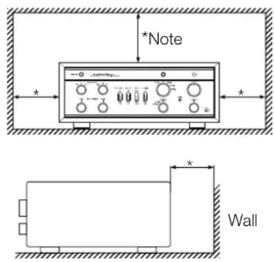
Precautions in connecting with other components
When connecting this unit with a CD/DVD player, tuner, or another input unit, turn off the power switches of this unit and all other connected units. Otherwise, a very strong noise may be generated and destroy the speakers.
In the worst case, this can cause equipment malfunction. The pin-plug to be inserted in each input terminal of this unit shall be pushed in firmly. If the grounding terminal is inadequately connected, noises including hum may be generated, resulting in an adverse S/N ratio.
The sound is not generated shortly after the power supply is turned on.
This amplifier is equipped with a time muting circuit in order to separate the output circuit.
Therefore, no sound will be generated shortly after the power supply is turned on. If the volume control is moved to a high sound level before the time muting circuit is canceled, a large sound is suddenly generated. We therefore advise initially setting the volume control at a low level. After that, you may move the volume control to your favorite sound level after the initial sound has come out of the speakers.
Batteries
Caution:
Batteries used for the remote control shall not be exposed to excessive heat such as sunshine, fire or the like.
Repair and adjustment
When repairs and adjustments are needed, please consult with the dealer where you bought the unit.
Cleaning
For cleaning, use a piece of soft cloth to wipe the unit such as cleaning cloth. When the dirt is hard to remove, use a small amount of neutral detergent to wipe, and then wipe the unit with dry cloth. Do not use a solvent like benzine or thinner because such a substance can damage the exterior.
Safety caution
Caution
This unit is a vacuum tube control amplifier. Be careful not to touch this product with your bare hand because it gets hot when the power is on. For safety, do not use this product in a place where children or unchained animals are present.
Front panel

1. Power switch (OPERATION)
Toggles the power on and off. When wiring or connection is performed, be sure to turn off this switch. When turning on the power switch again after turning the unit off, wait for more than one minute.
(It takes more than 30 seconds for the time mute to be reset again.)
2. Low frequency selector switch (frequency / Hz)
Toggles to select frequencies from 150 Hz, 300 Hz, 600 Hz. For example, when 150 Hz is selected, the frequencies of 150 Hz and lower can be adjusted by the tone control for bass.
3. High frequency selector switch (frequency / Hz)
Toggles to select frequencies from 1.5 kHz, 3 kHz, 6 kHz. For example, when 1.5 kHz is selected, the frequencies of 1.5 kHz and higher can be adjusted by the tone control for treble.
4. Tone defeat switch (tone defeat)
Toggles to bypass or activate tone controls.
off: Setting the switch to this position activates the tone controls and enables the user to adjust preferred tonal balance.
on: Setting the switch to this position bypasses the tone control circuit. At this time, operating the tone control will not change the tonal balance.
5. Low cut switch (low cut)
Toggles the low frequency cutoff function on and off. off: Provides the normal state.
on: Cuts low frequencies below 30 Hz at a -6 dB/oc-tave slope.
* This is useful when the woofers of speakers vibrate due to the warped record during record playback.
6. Mode selection switch (mode)
Changes the output mode.
mono: Mixes the signals from right and left channels.
stereo: Provides normal stereophonic reproduction.
7. Monitor switch (monitor)
Selects the monitor input terminal (MONITOR) on the rear panel.
on: Enables to reproduce the data from the recorder.
off: Enables to reproduce the data from the source selected with the input selector.
8. Input selector
Selects an input device such as a CD/DVD player or a tuner connected to each input terminal. This selector has 5 positions consisting of PHONO, CD, LINE-1, LINE-2, and LINE-3 that correspond to each input terminal on the rear panel. To select an input source, set the indicator to the position of the source to be reproduced.
9. Pilot light
Turns orange when the power is turned on.
10. Volume control (VOLUME)
Adjusts the sound volume.
Sound is not generated when this control is rotated counterclockwise to the end. The sound volume gradually becomes higher as the control is rotated clockwise.
11. Remote sensor (R)
Receives signals from the accessory remote control. Do not block the front of the photo receiver.
12. Sound volume indicator
Indicates the sound volume level.
This indicator blinks during the muting time immediately after turning on the power and at activating the mute function using the main unit or remote control.
13. Balance control (balance)
Adjusts the balance of sound volume between right and left channels. Rotating this knob counterclockwise makes the left sound volume enhanced, and rotating the knob clockwise makes the right sound volume enhanced. This knob shall be set to the center position under normal conditions, and rotated to make adjustment if necessary.
14. Mute button (mute)
Temporarily mutes the sound. Pressing this button activates the mute function and the sound volume indicator blinks. No sound is generated. Pressing this button again to cancel the mute function allows sound to be generated.
15. Cartridge selector (cartridge)
For analog record playback, the input selector should be set to PHONO, and adjusting the input impedance of the amplifier may be required depending on the impedance of the cartridge to be used.
The input impedance of the amplifier is selectable with the cartridge selector.
The selectable positions are MM, MC high, and MC low. Select a position in accordance with the input impedance specified in the owner's manual of the cartridge or to your taste.
| Cartridge selector MM MC high MC low | |||
| Impedance 47 kΩ 100 Ω 30 Ω | |||
16. Tone control for treble (treble)
Controls the frequency characteristics in the high frequency range. When this switch is set in the center position, flat frequency characteristics is obtained.
Rotating the knob clockwise makes the high frequency range enhanced, and rotating the knob counterclockwise makes the high frequency range attenuated.
17. Tone control for bass (bass)
Controls the characteristics in the low frequency range. When this knob is set to the center position, flat frequency characteristic is obtained.
Rotating the knob clockwise makes the low frequency range enhanced, and rotating the knob counterclockwise makes the low frequency range attenuated.
Names and Functions
Rear panel
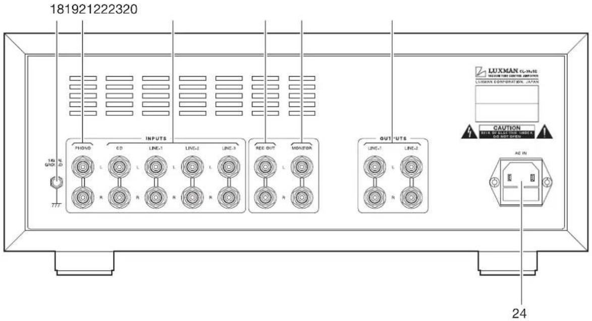
18. Signal ground terminal (SIGNAL GROUND)
Is a ground terminal for devices to be connected to this unit. This terminal is used to reduce noise when other devices are connected, and should be connected to an analog player or a tone arm. This terminal is not designed for safety.
19. Phono input terminal (PHONO)
Is an RCA input terminal to connect an analog player.
Some record players have internal phono equalizers. If that is the case, turn off the equalizer amplifier within the player.
Do not connect a CD player or other devices whose output level is high to this terminal. Normal playback cannot be provided due to sound crack.
20. Line input terminals (CD, LINE-1, LINE-2, LINE-3)
Are used for high-level signal inputs from a CD/DVD player, a SACD player, a tuner, a video deck, a TV, and other such devices. These input terminals offer the same functions.
21. Record output terminals (REC OUT)
Are used to transmit output signals for recording onto the recorder. These terminals are connected to the line input terminal of the recorder. The input signal selected with the input selector is outputted.
Do not insert shortpin plugs into REC OUT. No sound will be generated.
22. Monitor input terminals (MONITOR)
Are used to reproduce the line output from the recorder. These terminals are connected to the output terminal of the recorder.
23. Line output terminals (LINE-1, LINE-2)
These terminals take out the output of this unit. Two lines, LINE-1 and LINE-2, are provided, and same signals will be output from both lines. (Both are always on.)
While using one side of the line output terminals, do not insert shortpin plugs to the other line output terminals. No sound will be generated.
24. AC inlet (AC IN)
Connects the accessory power cable. The power shall be supplied from a household wall socket.
Connections

flowchart
graph TD
    A["CD PLAYER"] --> B["CD/SACD PLAYER"]
    B --> C["RECORDER"]
    C --> D["POWER AMPLIFIER"]
    D --> E["ANALOG PLAYER"]
    A --> F["Power Amplifier"]
    B --> G["Power Amplifier"]
    C --> H["Power Amplifier"]
Before Connecting
Before connecting other devices, connect the accessory power cable to the AC inlet of this CL-38uSE control amplifier.
When connecting, turn off the power supply of this unit and the power supplies of auxiliary devices to prevent unexpected accidents that may be caused by noise.
How to connect power supply
Use the accessory power cable and insert the AC plug in the outlet on the wall in the room where the unit is installed.
How to connect a CD player, SACD player, tuner, or other devices
Connect the output terminal of a device such as a CD player and the line input terminals (CD, LINE-1, LINE-2, or LINE-3) of the CL-38uSE control amplifier with 2 (R and L) pin-plug cables.
For LINE-1, LINE-2, and LINE-3 input terminals, connection in the same fashion as the CD input terminal provides the same playback.
How to connect an analog player
Connect the output terminal of the analog player and the PHONO terminals of this unit with 2 (R and L) pin-plug cables.
For some types of players, the ground wire from the phono motor or the tone arm should be connected to the ground terminal of this unit.
The phono equalizer section of this unit supports both the MM (moving magnet) type cartridge and MC (moving coil) type cartridge. Select the position of the cartridge selector according to the type of the cartridge to be used. There are low and high positions for MC. Select the position of the impedance closest to the value of the cartridge to be used.
| Cartridge selector MM MC high MC low | |||
| Impedance 47 kΩ 100 Ω 30 Ω | |||
The output from an analog player equipped with a phono equalizer or from an independent phono equalizer shall be connected to the line input terminals of this unit.
* During playback using an analog player, hum noises (boon noise) may be generated regardless of the sound of the record. Most of the time, the noise gets mixed from the tone arm section of the record player. Check the installed position of the record player and rearrange the cabling route if required.
Extra caution is required for the MC cartridge, since the output voltage is low.
* If the sound of the alalog player is distorted, it is likely that the appropriate stylus pressure is not applied to the cartridge. Make adjustment referring to the operating instructions of the record player and the cartridge.
If the player is equipped with an anti-skating function, its adjustment is also required.
* The sound may distorted due to dust adhered to the stylus.
In such a case, clean the stylus carefully with an available cleaner.
Connections

flowchart
graph TD
    A["CD PLAYER"] --> B["CD/SACD PLAYER"]
    B --> C["RECORDER"]
    C --> D["POWER AMPLIFIER"]
    D --> E["ANALOG PLAYER"]
    A --> F["Power Amplifier"]
    B --> G["Power Amplifier"]
    C --> H["Power Amplifier"]
    E --> I["Power Amplifier"]
How to connect a recorder
1. Connection to MONITOR terminals (playback)
Connect the line output terminal (LINE OUT) of a recorder and the MONITOR terminals of this unit with pin-plug cables in consideration of R and L.
When the monitor switch on the front panel is turned on, the playback of the recorder is possible.
2. Connection to REC OUT terminals (recording)
When the sound source from the various input devices is played back, such as the PHONO or LINE terminals of this unit, the signals are also provided to the REC OUT terminal. Connection between the REC OUT terminal of this unit and the line input terminals (LINE IN) of the recorder with pin-plug cables is required for recording on the recorder. You can enjoy listening to the sound from the speaker system and record the sound at the same time.
These output signals for recording are not affected by the control functions such as the volume control and tone control functions.
Do not insert shortpin plugs into REC OUT. No sound will be generated.
When a CD recorder, tape recorder, or other devices are connected, be aware that the playback sound volume becomes low or no sound is generated if the device decreases the impedance of the line input terminals of the recorder extremely or causes short-circuit on the line input terminals when the recording switch is set to on.
How to connect a power amplifier
Connect between the input terminal of an output device such as a power amplifier and a line output terminals (either LINE-1 or LINE-2) of this unit with a pin-plug cable. At this moment, exercise extra care not to conduct wrong connection between the right and left channels. If the right and left channels are connected reversely, the localization of sound images is deteriorated, thus failing in normal stereo playback.
If the grounding of the pin-plug cables is inadequately connected, noises including hum may be generated, resulting in an adverse S/N ratio. Surely insert the connection plug.
Before operation
- Ensure that the connections are correctly performed. (Normal playback cannot be achieved with wrong connections of R and L.)
- When the power is toggled between on and off or the input selector is changed over, set the volume control to the minimum position in advance.
Playback procedure
- Press the power switch after ensuring that the volume control is set to the minimum position.
- Select a source to be reproduced with the input selector.
- Adjust the sound level with the volume control.
- Operate the tone defeat switch, balance control, or tone control according to the reproduced source.
How to operate tone defeat
The tone defeat switch is used to play back with the shortest signaling route to prioritize the purity of the source selected with the input selector. When this switch is set to on, the tone control circuit is bypassed.
How to operate balance control
The balance control allows users to adjust the balance of sound volume between right and left channels.
When balance adjustment is not required, the balance control is set to the center position.
How to operate tone control
This unit has the tone control function for the low frequency and high frequency ranges.
The low frequency tone control (bass) is a function to adjust the tone range lower than the selected one with the selector switch (for low frequency). The tone control is set to flat frequency characteristic at the center position. Rotating the control clockwise makes the low frequency range enhanced, and rotating the control counterclockwise makes the low frequency range attenuated.
The high frequency tone control (treble) is a function to adjust the tone range higher than the selected one with the selector switch (for high frequency). The tone control is set to flat frequency characteristic at the center position. Rotating the control clockwise makes the high frequency range enhanced, and rotating the control counterclockwise makes the high frequency range attenuated.
For both the low frequency and high frequency ranges, the right and left channels interlockingly function.
When the tone defeat switch is set to on, the tone control does not function.
How to record a source
- Select a source to be recorded with the input selector.
- Play the source to be recorded and set the recorder to the recording state.
Operation of the tone control or balance control does not affect the recording signals.
Remote control RA-18
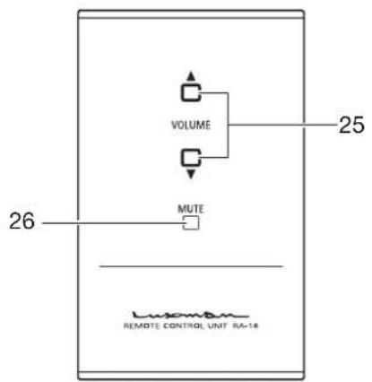
25. Volume (VOLUME ▲, ▼)
Adjusts the sound volume of the control amplifier. The button ▲ increases the sound volume, while the button ▼ decreases the sound volume.
26. Mute (MUTE)
Temporarily mutes the sound. Activation of the mute function causes the volume indicator on the main unit to blink, and no sound is generated. Pressing this button again to cancel the mute function allows sound to be generated.
Remote control
The remote control shall be aimed at the remote sensor (R) of this unit within the specified angle range shown in the illustration below.

Effective distance: approx. 5 meters
Dry cell battery [How to load dry cells]
- Put your finger on the battery cover claw located behind the remote control. The battery cover can be opened by sliding it downwards.
- Put 2 AAA batteries in the battery case as shown in the illustration.
- Close the battery cover.
![LUXMAN CL-38uSE - Dry cell battery [How to load dry cells] - 1](/content/2026/05/909886/images/8ba1480194f328dd3a878bbc67896629028f3adc4816ee282522ac85dd68c89a.jpg)
natural_image
Diagram of a mechanical component with a curved arrow indicating rotation or movement (no text or symbols present)* When the batteries start to lose power, the effective distance becomes shorter or the unit does not function even though the switch is pressed. In such a case, both of the batteries shall be replaced with new ones at the same time.
* If the remote control is not used for a long time, the batteries shall be removed from the case.
![LUXMAN CL-38uSE - Dry cell battery [How to load dry cells] - 2](/content/2026/05/909886/images/a6c0ec87291a6d74b6efc4cc234e7e6db53268728f8c13b1535c80f566588aa8.jpg)
flowchart
graph TD
    A["phano"] --> B["RY"]
    B --> C["BJM, MC H, MC L"]
    C --> D["RJ AMP"]
    D --> E["RF"]
    E --> F["boxer"]
    F --> G["balanceVR 100KMN 100KAA"]
    G --> H["TREBLE 50kΩ"]
    H --> I["Frequency/Hz 15x230V/60Hz 1.5kV/60kHz"]
    I --> J["mata"]
    J --> K["LINE OUT"]
    L["CD"] --> M["Input Selector"]
    M --> N["Low Cut"]
    N --> O["MODE Screen Medium"]
    O --> P["line defect"]
    Q["Izer 1"] --> R["Monitor"]
    S["Izer 2"] --> T["Monitor"]
    U["Izer5"] --> V["Monitor"]
    W["RGC OUT"] --> X["Monitor"]
    Y["+O"] --> Z["PMA LORTINOC ENOTEPLAT AMP"]
    style A fill:#f9f,stroke:#333
    style K fill:#ccf,stroke:#333
    style L fill:#cfc,stroke:#333
    style M fill:#fcc,stroke:#333
    style N fill:#cff,stroke:#333
    style O fill:#ffc,stroke:#333
    style P fill:#fcc,stroke:#333
    style Q fill:#cfc,stroke:#333
    style R fill:#fcc,stroke:#333
    style S fill:#cfc,stroke:#333
    style T fill:#fcc,stroke:#333
    style U fill:#cfc,stroke:#333
    style V fill:#fcc,stroke:#333
    style W fill:#cfc,stroke:#333
    style X fill:#fcc,stroke:#333
    style Y fill:#cfc,stroke:#333
    style Z fill:#fcc,stroke:#333
![LUXMAN CL-38uSE - Dry cell battery [How to load dry cells] - 3](/content/2026/05/909886/images/8c50093fdb42956839f77acd18f86e21494ce5a9760475abcead848bb4376b0c.jpg)
flowchart
graph TD
    A["Power Transformer"] --> B["CHOCF"]
    B --> C["VR LED MUTE SW"]
    D["Pute Operation SW"] --> E["AC source"]
    E --> F["RRC1"]
    F --> G["RRC2"]
    G --> H["Ground"]
    I["WIRELESS REMOTE CONTROLLER CIRCUIT"] --> J["LED F1"]
    J --> K["PHONE CP1 LINE1 LINE2 LINE3"]
    K --> L["MM MC1"]
    L --> M["MC-L"]
    M --> N["phone MM, MC-H, MC-I, sw"]
    O["Monitor command/option selector sw"] --> P["Line OUT SE"]
    Q["Line OUT SE"] --> R["Line OUT SE"]
| Total harmonic distortion 0.006 % (1 kHz, 1 V/50 kΩ) | |||
| 0.06 % (20 Hz to 20 kHz, 1 V/50 kΩ) | |||
| Input sensitivity/input impedance PHONO (MM) : 2.0 mV/47 kΩ | |||
| PHONO (MC-high) : 0.3 mV/100 Ω | |||
| PHONO (MC-low) : 0.08 mV/30 Ω | |||
| LINE : 190 mV/50 kΩ | |||
| RECORDER : 190 mV/50 kΩ | |||
| Maximum output voltage LINE-OUT : 19 V (THD 0.1 %, Load 50 kΩ) | |||
| S/N ratio PHONO (MM) : 70 dB or more (IHF-A correction, 2.0 mV input) | |||
| PHONO (MC-high) : 68 dB or more (IHF-A correction, 0.3 mV input) | |||
| PHONO (MC-low) : 65 dB or more (IHF-A correction, 0.08 mV input) | |||
| LINE : 100 dB or more (IHF-A weighted, input short) | |||
| Frequency response PHONO (MM) : 20 Hz to 20,000 Hz (±0.5 dB, tone defeat on) | |||
| PHONO (MC-high) : 20 Hz to 20,000 Hz (±0.5 dB, tone defeat on) | |||
| PHONO (MC-low) : 20 Hz to 20,000 Hz (±0.5 dB, tone defeat on) | |||
| LINE : 10 Hz to 70,000 Hz (within -3 dB, tone defeat on) | |||
| Tone control BASS (150 Hz) : ±8.0 dB at 50 Hz | |||
| BASS (300 Hz) : ±8.0 dB at 100 Hz | |||
| BASS (600 Hz) : ±8.0 dB at 200 Hz | |||
| TREBLE (1.5 kHz) : ±8.0 dB at 5 kHz | |||
| TREBLE (3 kHz) : ±8.0 dB at 10 kHz | |||
| TREBLE (6 kHz) : ±8.0 dB at 20 kHz | |||
| Low cut | 30 Hz (-6 dB/oct.) | ||
| Input | 1 phono line (MM/MC high/MC low supported) and 4 lines | ||
| Recording input/output | 1 line for each of recording output and monitor input | ||
| Output | 2 Lines | ||
| Supplied functions | [Front panel] | ||
| Power switch | Sound volume | Mute | |
| Balance | Input selector | ||
| Turnover frequency selector switch | |||
| Cartridge selector (MM/MC high/MC low) | |||
| Tone control | Low cut | Mode | |
| Monitor | |||
| [Rear panel] | |||
| Input/output terminals | Signal ground terminal | AC inlet | |
| [Remote control function] | |||
| Sound volume (up/down) | Mute | ||
| Circuit | SRPP | ||
| Vacuum tube used | 3×ECC803S, 5×ECC802S | ||
| Accessories | Remote control RA-18 | Power cable | |
| Terminal protection cap | Owner's Manual | ||
| Safety cautions | 2 pieces of “AAA” batteries | ||
| Power supply | 230 V ~ (50 Hz) | ||
| Power consumption | 35 W | ||
| Max. external dimensions | 402 (W) x 169 (H) x 307 (D) mm | ||
| Weight | 13.5 kg (main unit) | ||
* Specifications and appearance are subject to change without notice.
Before Asking for Repair Services
While the unit is used, an unusual phenomenon may be confused as a malfunction for a certain reason. Prior to asking our official sole distributor of your country for repair services, please check the table below and read the operating instructions for the subsidiary devices. If the cause of the malfunction cannot be identified, please contact your dealer. When we have once accepted your request for repair services, inspection fees and traveling expenses may be claimed even though the unit is found to be normal.
Problem Cause Solution
| No power is supplied even though the power switch is pressed ON. | The power plug is disconnected from the wall outlet, or it is not completely inserted. | Insert the power plug in the wall outlet completely. |
| The power plug is disconnected from the AC inlet, or it is not inserted completely. | Securely insert the power plug in the AC inlet completely. | |
| No sound is generated.(Both L and R) | The volume control is set at the minimum level. | Rotate the volume control clockwise to adjust the sound volume. |
| The volume is muted. Cancel the MUTE mode. | ||
| The input selector is not set to the source position to be played back. | Set the input selector correctly. | |
| Cable connections are incomplete. Make cable connections securely. | ||
| The output level of the input device is set to the minimum position. | Adjust the output level. | |
| No sound comes out from one side. | The connecting cable is not connected on one side only. | Make cable connections securely. |
| Humming sound (boon or zzz noise) is generated. | The ground side of the pin-plug cable has no contact with the terminal. | Make connections securely so that the ground side of the pin-plug cable makes contact with the terminal. |
| The ground wire of the record player is not connected. | Connect the ground wire of the record player to the SIGNAL GND terminal. | |
| Connections or mounting conditions are incomplete between the cartridge and shell, or between the shell and tone arm of the record player. | Connect (or mount) the cartridge, shell, and tone arm securely. | |
| The connecting cables are too close to the power cable. | Keep the connecting cables away from the power cable. | |
| Induction noise is picked up from a power transformer of another device. | Install it distant from other devices. | |
MEMO

- Installation place
- Ventilation holes
- Note:
- Precautions in connecting with other components
- The sound is not generated shortly after the power supply is turned on.
- Batteries
- Caution:
- Repair and adjustment
- Cleaning
- Safety caution
- Caution
- Power switch (OPERATION)
- Low frequency selector switch (frequency / Hz)
- High frequency selector switch (frequency / Hz)
- Tone defeat switch (tone defeat)
- Low cut switch (low cut)
- Mode selection switch (mode)
- Monitor switch (monitor)
- Input selector
- Pilot light
- Volume control (VOLUME)
- Remote sensor (R)
- Sound volume indicator
- Balance control (balance)
- Mute button (mute)
- Cartridge selector (cartridge)
- Tone control for treble (treble)
- Tone control for bass (bass)
- Names and Functions
- Signal ground terminal (SIGNAL GROUND)
- Phono input terminal (PHONO)
- Line input terminals (CD, LINE-1, LINE-2, LINE-3)
- Record output terminals (REC OUT)
- Monitor input terminals (MONITOR)
- Line output terminals (LINE-1, LINE-2)
- AC inlet (AC IN)
- Connections
- Before Connecting
- How to connect power supply
- How to connect a CD player, SACD player, tuner, or other devices
- How to connect an analog player
- How to connect a recorder
- Connection to MONITOR terminals (playback)
- Connection to REC OUT terminals (recording)
- How to connect a power amplifier
- Before operation
- Playback procedure
- How to operate tone defeat
- How to operate balance control
- How to operate tone control
- How to record a source
- Volume (VOLUME ▲, ▼)
- Mute (MUTE)
- Remote control
- Dry cell battery [How to load dry cells]
- Before Asking for Repair Services
- MEMO
Brand : LUXMAN
Model : CL-38uSE
Category : Audio Amplifier