
MSS140 - Warming Drawer BORA - Free user manual and instructions
Find the device manual for free MSS140 BORA in PDF.


| Product Type | Warming Drawer |
| Brand | BORA |
| Model | MSS140 |
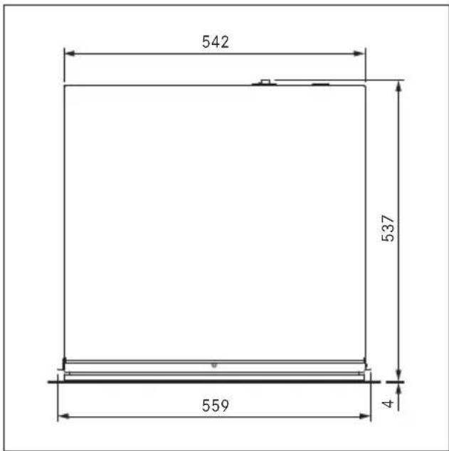
| Appliance Dimensions (H x W x D) | 140 x 559 x 537 mm |
| Recess Dimensions (H x W x D) | 140 x 560 x 560 mm |
| Cooking Chamber Dimensions (H x W x D) | 97 x 525 x 410 mm |
| Cooking Chamber Volume | 20 litres |
| Maximum Load Capacity | 25 kg |
| Net Weight | 18.2 kg |
| Supply Voltage | 220 – 240 V |
| Frequency | 50 – 60 Hz |
| Maximum Power Consumption | 810 W |
| Fuse Protection | 16 A |
| Temperature Control Range | 30 – 100 °C |
| Temperature Levels | 6 (30, 40, 60, 70, 80, 100 °C) |
| Time Levels | 6 (30 min, 1, 2, 3, 4, 6 hrs) |
| Operating Modes | Manual, Preset Programmes (Warm crockery, Reheat food, Keep warm, Defrost, Low-temperature cooking), Delayed start, Demo mode |
| Special Features | Push2Open, LED oven chamber lighting, Touch control, BORA Connectivity, Adjustable drawer front |
| Drawer Front | Replaceable; compatible with unit front or glass front (MSF140 glass front included) |
| Installation Type | Built-in; can be combined with other multi-drawers or X BO steam oven |
| Cleaning and Maintenance | Soft cloth with mild detergent; no abrasive cleaners, steam cleaners, or aggressive chemicals |
| Safety Features | Automatic switch-off, residual heat warning, child safety (supervision required for children 8+) |
| Spare Parts and Repairability | Only original spare parts; repairs by BORA service team |
| Warranty | 2 years manufacturer's warranty (extendable to 3 years via registration at mybora.com) |
| Accessories Included | Glass front MSF140, power cable, communication cable, installation jig, mounting angles, screws, sealing lip, decorative trims |
| Optional Accessories | Shelf rack MSER (for MS290/MSS290 model; compatible with MSS140? – not specified) |
| Mains Cable Length | 180 cm |
| Mains Cable Plug Type | C13/E+F |
Frequently Asked Questions - MSS140 BORA
User questions about MSS140 BORA
0 question about this device. Answer the ones you know or ask your own.
Ask a new question about this device
Download the instructions for your Warming Drawer in PDF format for free! Find your manual MSS140 - BORA and take your electronic device back in hand. On this page are published all the documents necessary for the use of your device. MSS140 by BORA.
USER MANUAL MSS140 BORA
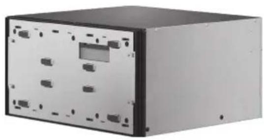
EN MS290/MS140, MSS290/MSS140 operating and installation instructions
Multi-drawer 290 mm/140 mm
Multi-drawer set 290 mm/140 mm including glass front
natural_image
Exterior view of a black rectangular electronic device with multiple ports and mounting holes (no visible text or symbols)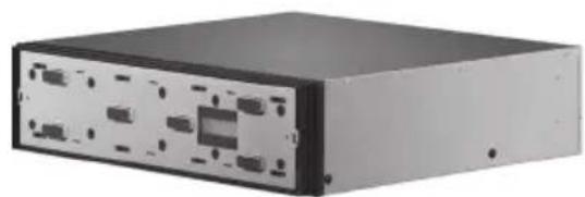
natural_image
Exterior view of a black rectangular electronic device with multiple ports and mounting holes (no visible text or labels)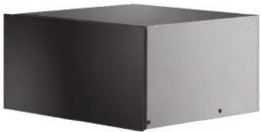
natural_image
Exterior view of a modern office building (no signage)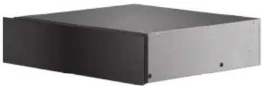
natural_image
Exterior view of a black rectangular electronic device casing (no visible text or symbols)003290-10001-02
bora.com
Table of Contents
1 General information 49
1.1 Liability 49
1.2 Validity of the operating and installation instructions....49
1.3 Product conformity.... 49
1.4 Presentation of information......49
2 Safety 51
2.1 Use as intended....51
2.2 People with limited abilities.... 51
2.3 General safety instructions.... 52
2.4 Safety instructions for installation......54
2.5 Safety instructions - operation......55
2.6 Safety instructions – cleaning and maintenance 56
2.7 Safety instructions – repairs, servicing and spare parts.... 57
2.8 Safety instructions – disassembly and disposal 57
3 Technical data 59
4 Appliance description 62
4.1 Model description....62
4.2 Structure 62
4.3 How it works 63
4.4 Touch operating panel....63
4.5 LED oven chamber lighting....64
4.6 Shelf rack 64
5 Functions and operation 65
5.1 Opening and closing the drawer 65
5.2 Touch control 65
5.3 Initial operation....66
5.4 Load capacity....66
5.5 Switching on and off 66
5.6 Manual operation.... 66
5.7 Using preset programmes 67
5.7.1 Preset programmes....67
5.7.2 Using preset programmes....68
5.8 Delayed start....68
5.9 Standby mode....68
5.10 BORA Connectivity 69
5.11 Demo mode....69
5.12 Factory settings....69
6 Applications 70
7 Cleaning and maintenance 72
7.1 Cleaning agents 72
7.2 Cleaning the exterior....72
7.3 Cleaning the cooking chamber....72
8 Troubleshooting 73
9 Installation 74
9.1 Scope of delivery....74
9.2 Tools and aids 74
9.3 Assembly instructions....75
9.3.1 Possible appliance combinations....75
9.3.2 Fitted unit (single installation)....75
9.3.3 Multi-drawer fitted unit + X BO steam oven....76
9.4 Installing the appliance....76
9.5 Fitting the front....78
9.5.1 Fitting the unit front 78
9.5.2 Fitting the glass front (MSF290/MSF140) ...80
9.5.3 Completing installation....81
9.6 Function test....82
9.7 Handover to user....82
10 Decommissioning, disassembly and disposal83
10.1 Decommissioning 83
10.2 Disassembly....83
10.3 Environmentally-friendly disposal 83
11 Warranty, technical service, spare parts, accessories 84
11.1 BORA manufacturer's warranty....84
11.2 Service....85
11.3 Spare parts.... 85
11.4 Accessories....85
1 General information
These instructions contain important information to protect you from injury and prevent damage to the appliance.
Please read these instructions carefully before installing or using the appliance for the first time.
Other documents apply alongside these instructions. Please by all means adhere to all documents that form part of the scope of delivery.
Assembly, installation and commissioning must always occur in line with national laws, regulations and standards. The work must be performed by qualified specialists who are familiar with and comply with the supplementary regulations of the local utility companies.
All safety and warning information as well as the handling instructions in the accompanying documents must be observed.
1.1 Liability
BORA Holding GmbH, BORA Vertriebs GmbH & Co KG, BORA APAC Pty Ltd and BORA Lüftungstechnik GmbH – hereinafter referred to as BORA – does not assume any liability for damage arising from disregard for or non-adherence to the documents included in the scope of delivery!
Furthermore, BORA shall not be held liable for damage caused by improper installation or failure to observe the safety and warning instructions!
1.2 Validity of the operating and installation instructions
These instructions apply to several appliance versions. It is therefore possible that some of the features described do not apply to your appliance. The details of the figures contained herein may differ from some appliance versions and are to be understood as schematic diagrams.
1.3 Product conformity
Directives
The appliances meet the following EU/EC directives:
2014/30/EU EMC Directive
2014/35/EU Low Voltage Directive
2009/125/EC Ecodesign Directive
2011/65/EU RoHS Directive
1.4 Presentation of information
We use standard formatting, numbering, symbols, safety instructions, terms and abbreviations so that you can work quickly and safely when using this manual.
The term “appliance” is used to refer to cooktops, cooktop extractors or cooktops with integrated cooktop extractor.
Instructions are indicated with an arrow.
▶ Always follow all instructions in the prescribed order.
Enumerations are indicated with a bullet point at the start of the line:
- Enumeration 1
- Enumeration 2
Information notes point to special features that must be taken into account.
Safety and warning instructions
The safety and warning instructions in this manual are emphasised with symbols and signal words.
Safety and warning instructions are structured as follows:
WARNING SYMBOL AND SIGNAL WORD!
Type and source of danger
Results of non-compliance Measures to minimise risk
Please note:
- warning symbols draw attention to a high risk of injury.
- The signal word indicates the severity of that risk.
Warning symbol Signal word Risk

Danger Indicates an
immediate, hazardous situation which causes death or serious injury if not respected.

Warning Indicates a potentially hazardous situation which can cause death or serious injury if not respected.
Caution Indicates a potentially hazardous situation which can cause minor injury or damage to property if not respected.
Tab. 1.1 Meaning of the warning symbols and signal words
Figures
All measurements are provided in millimetres.
2 Safety
The appliance complies with the stipulated safety requirements. The user is responsible for the safe use of the appliance, cleaning and maintenance. Improper use can lead to personal injury and damage to property.
2.1 Use as intended
The appliance can be used to warm crockery and prepare food in private households. Under no circumstances should the heat drawer be used for flambéeing or heated up with large amounts of oil or fat inside.
This appliance is not intended for:
● drying animals, textiles or paper
- outdoor use
- heating rooms
● cooling, ventilating or dehumidifying rooms
● use in mobile installation sites such as motor vehicles, ships or aeroplanes
● use at altitudes of over 2,000 m (metres above sea level)
● use when not fully installed
Any other use or any use that goes beyond that which is described here is classed as unintended.
BORA does not assume any liability for damages caused by incorrect installation, improper use or incorrect operation.
All misuse is prohibited!
2.2 People with limited abilities
Children
The appliance can be used by children aged 8 and over if they are supervised or have been instructed how to use the appliance safely and understand the resultant risks. Children must not play with the appliance.
Supervise children in the vicinity of the appliance.
i Any work involving cleaning and maintenance must not be carried out by children unless they are supervised at all times while doing so.
People with reduced physical, sensory or mental capacities
The appliance can be used by people with reduced physical, sensory or mental capacities or a lack of experience and/or knowledge if they are supervised or have been instructed how to use the appliance safely and understand the resultant risks.
2.3 General safety instructions
ANGER!
Packaging components are a choking hazard
Packaging components (e.g. film, polystyrene) can be life-threatening for children.
Store all packaging components out of reach of children.
Dispose of the packaging properly and immediately.
ANGER!
Risk of electric shock or injury from damaged surfaces
The underlying electronics can be exposed or damaged due to fissures, fractures or cracks in appliance surfaces (e.g. damaged glass), particularly in the vicinity of the operating unit. This can cause an electric shock. Furthermore, a damaged surface can cause injuries.
Do not touch the damaged surface.
If there are any cracks, fissures or fractures, switch the appliance off immediately.
Safely disconnect the appliance from the mains using the LS switch, fuses, automatic circuit breakers or contactor.
Contact BORA Service.
WARNING!
Risk of injury or damage due to incorrect components or unauthorised modifications
Incorrect components can lead to personal injury or damage to the appliance. Modifications, additions or alterations to the appliance can lead to safety risks.
Only use original components.
Do not make any modifications, additions or alterations to the appliance.
WARNING!
Risk of injury due to mechanical damage on the appliance
Mechanical damage (e.g. cracks, deformation, separation of adhesive seals, etc.) to the appliance, as well as to cables and accessories can cause injuries.
Do not operate the appliance.
Try not to repair or replace damaged components yourself.
Contact BORA Service.
CAUTION!
Appliance components can cause injury if dropped
Appliance components can cause injury if dropped.
Place any appliance components that have been removed in a safe place near the appliances.
Ensure that no components removed from the appliances can fall on the floor.
CAUTION!
Risk of injury from heavy lifting
If not handled correctly, carrying and installing appliances can cause injury to the limbs or torso.
if necessary, carry and install the appliance with another person.
Use appropriate aids to prevent damage or injury.
CAUTION!
Damage from improper use
The appliance surfaces must not be used as work surfaces. This can damage the appliances (particularly in the case of hard and sharp objects).
Cutting with knives or cutting wheels in the drawer causes visible damage.
Do not use the appliance as a worktop.
Keep hard or sharp objects away from the appliance surfaces.
Do not sit or lean on the drawer.
Faults and errors
In the case of faults and errors in the “Troubleshooting” chapter.
In the event of any faults or errors that are not mentioned, switch the appliance off and contact BORA Service.
Pets
Keep pets away from the appliance.
2.4 Safety instructions for installation
The appliance must only be installed and assembled by trained specialists who are familiar with and comply with the standard national regulations and supplementary regulations of the local utility companies.
i Work on electrical components must only be conducted by trained electrical personnel.
The electrical safety of the appliance is only guaranteed if it is connected to a protective conductor system that has been installed in line with regulations. Ensure that this basic safety precaution is met.
The appliance must be suitable for the regional voltage and frequency.
Check the information on the identification plate and in the event of deviations, do not connect the appliance.
Only use the connection cables supplied. Where necessary these are included in the scope of delivery.
Do not use the appliance until installation is complete. This is the only way to ensure safe operation.
Conduct all work extremely attentively and conscientiously and in accordance with these instructions.
Before handing the appliance or system over to the end user, ensure that it has been correctly installed.
ANGER!
Risk of electric shock from damaged appliance
A damaged appliance can cause an electric shock.
Check the appliance for visible damage prior to installation.
Do not install or connect any damaged appliances.
Do not operate any damaged appliances.
DANGER!
Risk of electric shock from damaged power supply cable
If the power supply cable is damaged (e.g. during installation or by coming into contact with hot cooking surfaces), this can cause an (lethal) electric shock.
Make sure that the power supply cable does not become trapped or damaged.
Make sure that the power supply cable does not come into contact with hot cooking surfaces.
2.5 Safety instructions – operation
Do not use the appliance until installation is complete. This is the only way to ensure safe operation.
Do not use the appliance as a storage surface.
Switch off the appliance after use.
WARNING!
Risk of burns from hot surfaces.
The appliance and exposed parts (oven chamber, door, heating elements, accessories) become hot during use. Touching hot surfaces can cause serious burns.
Do not touch hot surfaces.
Please use suitable accessories when needed (pot holders, oven gloves).
Keep children under 8 years of age away from the appliance or ensure they are supervised at all times.
WARNING!
Risk of burns due to power cut
During or after a power cut a cooktop that was previously in operation may still be hot.
Do not touch the appliance while it is still hot.
Keep children away from the hot appliance.
DANGER!
Risk of fire from overheated oil or fat
Oil or fat in the pot can quickly heat up and ignite.
Never extinguish oil and fat fires with water.
Switch off the appliance.
Extinguish the fire using a pan lid or a fire blanket, for example.
DANGER!
Risk of fire from overdrying
When food is overdried there is a risk of fire.
Do not leave the appliance unattended if you are dessicating or drying herbs, bread, mushrooms, etc.
If you see smoke, keep the appliance closed and switch off the electricity supply.
WARNING!
Risk of burning and fire from hot objects
The appliance and its exposed parts are hot during operation and the cooling phase. Objects in contact with hot appliance components heat up very quickly and can cause severe burns (this particularly applies to metal objects such as knives, forks, spoons, lids or appliance components) or catch fire.
Please use suitable accessories (pot holders, oven gloves).
DANGER!
Risk of burns or explosion caused by flammable liquids
Flammable liquids can be ignited by hot food or explode and cause serious injuries.
Do not pour flammable liquids (e.g. spirits) over hot food.
WARNING!
Risk of injury from moving appliance parts
There is a risk of injury when opening and closing the door/drawer.
Ensure that nobody reaches into the appliance when the door/drawer is being opened or closed (children in particular).
WARNING!
Risk of injury from open door/drawer
When the door/drawer is open there is a risk of tripping or crushing.
Close the door/drawer after use.
CAUTION!
Damage caused by opening the drawer brusquely
If the drawer is not opened carefully, this can cause damage.
Do not open the drawer brusquely.
Only open the drawer as described in the “Operation” chapter.
2.6 Safety instructions – cleaning and maintenance
The appliance must be cleaned at regular intervals. Dirt can lead to damage, restriction of functions, or bothersome odours. In the worst case scenario, this can become a hazard.
Remove dirt immediately.
When cleaning, only use non-abrasive detergents to prevent scratching and abrasion on the surface.
When cleaning, ensure that no water penetrates the appliance. Use only a slightly damp cloth. Never spray the device with water. Water penetration can cause damage!
Do not use a steam cleaner for cleaning. Steam can cause a short circuit on live parts and thus lead to property damage.
Please follow all instructions in the “Cleaning and Maintenance” chapter.
CAUTION!
Risk of corrosion
Moisture may form during operation.
Leave the drawer slightly open after use (during the cooling phase).
Do not use any objects in the multi-drawer that may rust.
2.7 Safety instructions – repairs, servicing and spare parts
The appliance must only be repaired and serviced by trained specialists who are familiar with and comply with the standard national regulations and supplementary regulations of the local utility companies.
i Work on electrical components must only be conducted by trained electrical personnel.
Before any repair work, safely disconnect the appliance from the mains supply.
WARNING!
Risk of injury or damage from improper repairs
Incorrect components can lead to personal injury or damage to the appliance. Modifications, additions or alterations to the appliance can lead to safety risks.
Only use original spare parts for repairs.
Do not make any modifications, additions or alterations to the appliance.
A damaged power supply cable must be replaced by a suitable power supply cable. This may only be done by an authorised member of the After Sales Service team.
2.8 Safety instructions – disassembly and disposal
The appliance must only be disassembled by trained specialists who are familiar with and comply with the standard national regulations and supplementary regulations of the local utility companies.
i Work on electrical components must only be conducted by trained electrical personnel.
Before disassembly, safely disconnect the appliance from the mains supply.
3 Technical data
MS290/MSS290
| Parameter Value | |
| Supply voltage | 220 - 240 V |
| Frequency 50 - 60 Hz | |
| Maximum power consumption 810 W | |
| Fuse protection 1 x 16 A | |
| Dimensions(width x depth x height) | |
| MS290 | 559 x 537 x 290 mm |
| glass front (included with MSS290) | 595 x 4 x 288 mm |
| Recess dimensions(width x depth x height) | 560 x 560 x 290 mm |
| Cooking chamber dimensions(width x depth x height) | 525 x 410 x 247 mm |
| Cooking chamber volume 50 l | |
| Maximum load 25 kg | |
| Weight(incl. accessories/packaging) | |
| MS290 | 24 kg |
| MSS290 | 27.6 kg |
| Weight | |
| MS290 | 20.7 kg |
| MSS290 | 23.9 kg |
| Time levels | 1 - 6 |
| Temperature levels 1 - 6 | |
| Temperature control range 30 - 100°C | |
| Mains supply cable length 180 cm | |
| Mains supply cable plug type C13/E+F | |
Tab. 3.1 MS290/MSS290 technical data
MS140/MSS140
| Parameter Value | |
| Supply voltage | 220 - 240 V |
| Frequency 50 - 60 Hz | |
| Maximum power consumption 810 W | |
| Fuse protection 1 x 16 A | |
| Dimensions(width x depth x height)MS140 glass front (included with MSS140) | 559 x 537 x 140 mm595 x 4 x 138 mm |
| Recess dimensions(width x depth x height) | 560 x 560 x 140 mm |
| Cooking chamber dimensions(width x depth x height) | 525 x 410 x 97 mm |
| Cooking chamber volume 20 l | |
| Maximum load 25 kg | |
| Weight(incl. accessories/packaging)MS140 MSS140 | 19.2 kg21.3 kg |
| WeightMS140 MSS290 | 16.4 kg18.2 kg |
| Time levels | 1 - 6 |
| Temperature levels 1 - 6 | |
| Temperature control range 30 - 100°C | |
| Mains supply cable length 180 cm | |
| Mains supply cable plug type C13/E+F | |
Tab. 3.2 MS140/MSS140 technical data
MS290 appliance dimensions
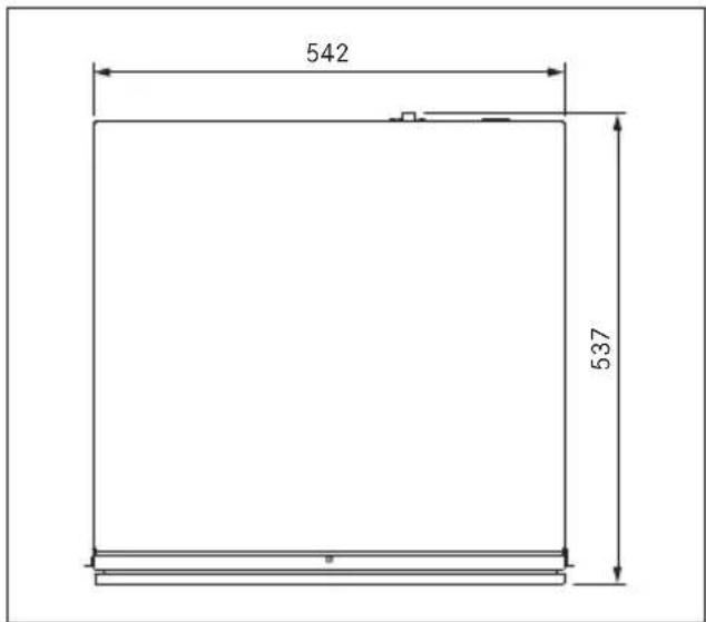
Fig. 3.1 MS290 appliance dimensions top view
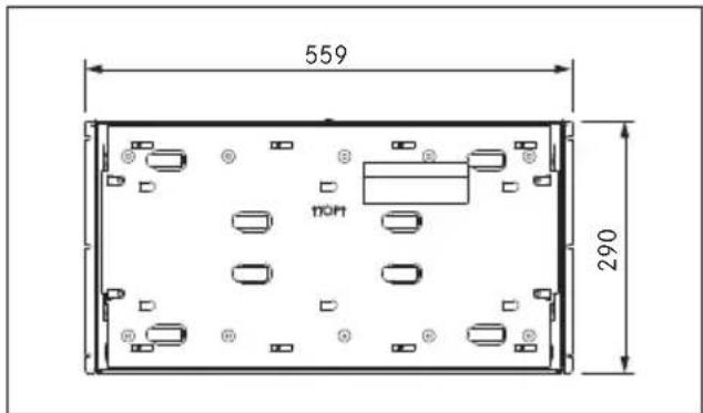
Fig. 3.2 MS290 appliance dimensions front view
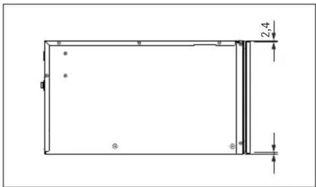
Fig. 3.3 MS290 appliance dimensions side view
MSS290 appliance dimensions
other
| Dimension | Value | | --------- | ----- | | Top Left | 542 | | Middle Right | 537 | | Bottom Right | 559 | | Right | 4 |Fig. 3.4 MSS290 appliance dimensions top view
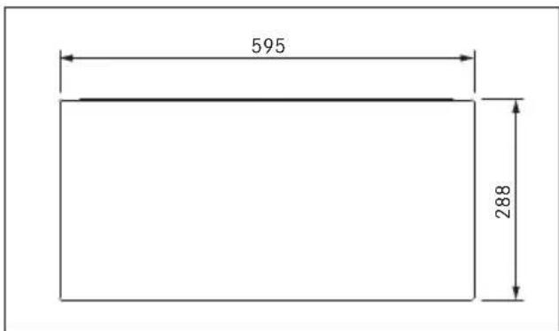
Fig. 3.5 MSS290 appliance dimensions front view
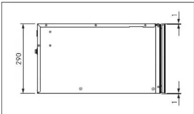
Fig. 3.6 MSS290 appliance dimensions side view
MS140 appliance dimensions
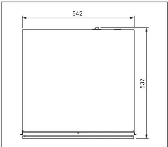
Fig. 3.7 MS140 appliance dimensions top view
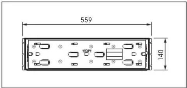
Fig. 3.8 MS140 appliance dimensions front view
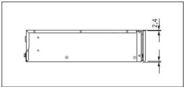
Fig. 3.9 MS140 appliance dimensions side view
MSS140 appliance dimensions
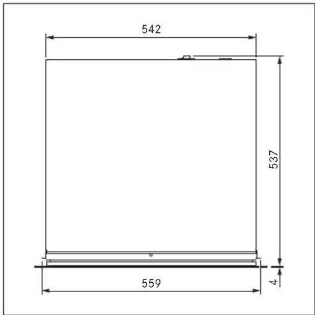
other
| Dimension | Value | | --------- | ----- | | Top Height | 542 | | Middle Height | 537 | | Bottom Height | 559 | | Right Height | 4 |Fig. 3.10 MSS140 appliance dimensions top view
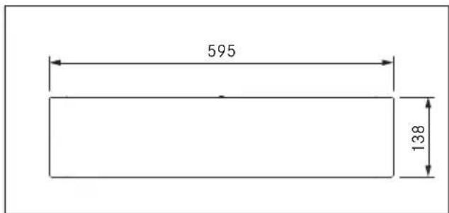
Fig. 3.11 MSS140 appliance dimensions front view
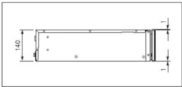
Fig. 3.12 MSS140 appliance dimensions side view
4 Appliance description
Appliance features
- Individual control options – operation possible via manual temperature and time control or preset programmes.
- Push2Open – easy opening by lightly pressing the front of the drawer.
- BORA Connectivity – expanded operating options and range of functions thanks to networking with X BO steam oven.
- LED oven chamber lighting – the contents of the drawer are illuminated even when the drawer is fully extended.
- Changeable drawer front – can be fitted with a unit front or glass front (MSF140, MSF290).
4.1 Model description
| Model Long description |
| MS290 Multi-drawer 290 mm |
| MSS290 Multi-drawer set 290 mm incl. glass front (1x MS290, 1x MSF290) |
| MS140 Multi-drawer 290 mm |
| MSS140 Multi-drawer set 140 mm incl. glass front (1x MS140, 1x MSF140) |
Tab. 4.1 Model description
4.2 Structure
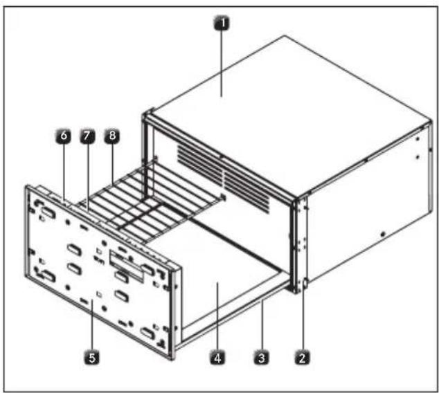
Fig. 4.1 Multi-drawer structure
[1] Housing
[2] Mounting angle with decorative trim (left and right)
[3] Drawer
[4] Heated glass base
[5] Front support
[6] Touch operating panel
[7] LED oven chamber lighting
[8] Shelf rack (in MS290, MSS290)
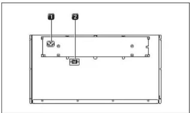
Fig. 4.2 Back of multi-drawer
[1] Mains supply cable socket
[2] Communication cable socket
4.3 How it works
The appliance has two heating systems:
- drawer with heated glass base
• recirculation heating
The appliance does not heat up until the drawer is completely closed.
4.4 Touch operating panel
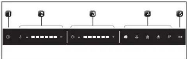
Fig. 4.3 Touch operating panel
[1] Power button
[2] Temperature settings
[3] Time settings
[4] Preset programmes
[5] BORA Connectivity (active connection to X BO)
The multi-drawer is operated via a central operating panel. The operating panel is equipped with indicators and controls (electronic sensor buttons). The sensor buttons respond to finger contact.
Indicator symbols
| Temperature display | |
| Time display | |
| B→ | BORA Connectivity active |
| Temperature levels | |
| 30 °C | |
| 40 °C | |
| 60 °C | |
| 70 °C | |
| 80 °C | |
| 100 °C | |
| Time levels | |
| 30 min. | |
| 1 hr | |
| 2 hrs | |
| 3 hrs | |
| 4 hrs | |
| 6 hrs | |
Tab. 4.2 Indicators
Control symbols
| 1 | Power button Switch on/off | |
| - | Minus button Reduce the temperature or time | |
| + | Plus button Increase the temperature or time | |
| Presets (programmes) | ||
| Warm crockery Temperature 60 °C Time 1 hr | ||
| Reheat food Temperature 100 °C Time 1 hr | ||
| Keep food warm Temperature 70 °C Time 3 hrs | ||
| Defrost food Temperature 30 °C Time 4 hrs | ||
| Cook at low-temperature | Temperature 80 °C Time 6 hrs | |
Tab. 4.3 Controls
The temperatures refer to the surface of the heated glass base when the appliance is empty. Measurements by the user can be inaccurate and are not suitable for checking the exact temperature.
On certain temperature settings, the appliance automatically overheats to start with. This enables target temperatures to be reached faster.
4.5 LED oven chamber lighting
The LED oven chamber lighting is activated when the drawer is opened.
If the open drawer is not operated in standby mode, the LED oven chamber lighting is deactivated after 5 minutes.
The LED oven chamber lighting is automatically deactivated when the drawer is closed.
4.6 Shelf rack
In the case of the multi-drawer MS290/MSS290, the loading area can be extended using the shelf rack provided.
The shelf rack is also suitable for dishes that should be heated at a lower temperature than those being kept warm on the multi-drawer's heated glass base. The shelf rack can also be used to preheat crockery, whereas food can be heated at a higher temperature on the heated glass base.
Up to 2 shelf racks can be used in the drawer at the same time.
The MSER shelf rack is available as an accessory.
5 Functions and operation
Observe all safety and warning information during Closing operation (see „2 Safety“).
If the drawer is opened during operation, it will stop working. The remaining time and set temperature level will be displayed. As soon as the drawer is closed again, operation will be resumed on the previously active settings.
Risk of burns! The surfaces inside the appliance may still be hot after use.
5.1 Opening and closing the drawer
Opening
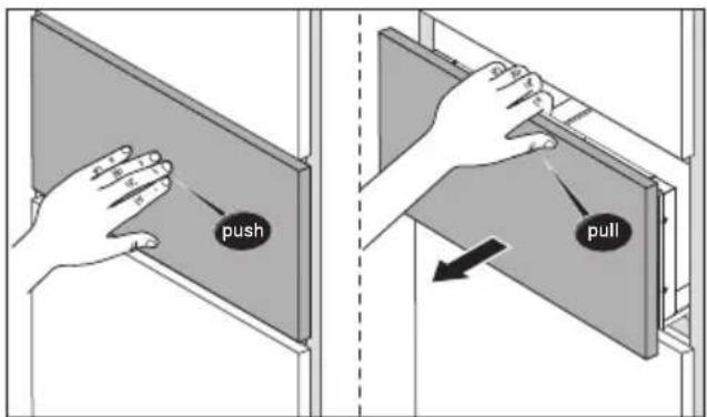
Fig. 5.1 Opening the drawer
▶ Press the front of the drawer lightly in the centre with one hand (Push2Open).
- This unlocks and opens the drawer. It can then be fully opened by hand.
• The oven chamber lighting is activated.
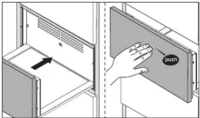
Fig. 5.2 Closing the drawer
▶ Press the front of the drawer lightly in the centre with one hand until the drawer is closed and clicks into place.
If the drawer is not opened or closed carefully, this can cause damage. Do not open or close the drawer roughly. Never yank the drawer open.
5.2 Touch control
Operate the appliance by tapping the corresponding symbol (control) on the touch operating panel with your finger (see „4.4 Touch operating panel“). The controls react to different touch commands:
Command Contact Time
Tap brief touch < 1 s
Long press long touch 1-5 s
Tab. 5.1 Touch commands
The touch operating panel must be clean and dry in order for it to work.
If touch commands do not work or are not working properly, the following should be noted:
- Tap the touch zones with only one finger.
-
Do not rest the heel of your hand on the touch operating panel.
-
Keep the contact area as small as possible when using the touch zones.
- Ensure that your fingers are clean and dry.
5.3 Initial operation
▶ Clean the appliance, particularly the interior.
▶ Ensure that there are no objects inside the drawer.
▶ Heat up the appliance before using for the first time (temperature level 6, time level 3).
When heated for the first time, odours may form.
5.4 Load capacity
The multi-drawer can hold a maximum load of 25 kg. If this weight is exceeded, it may damage the appliance.
▶ Only use suitable, heat-resistant containers.
Examples of load capacity for crockery
Load capacity Crockery MS140 MS290
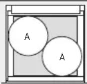
A 12 pcs. 40 pcs.
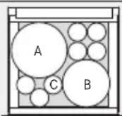
A/B/C 6 pcs. 20 pcs.
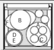
A/B/C 4 pcs. 12 pcs.
D/E
F
1 pc.
1 pc.
2 pcs.
1 pc.
2 pcs.
A = plates (27 cm)
B = soup dishes (23 cm)
C = cups (9 cm)
D = bowls (17 cm)
E = bowls (19 cm)
F = trays (34 cm)
Tab. 5.2 Examples of load capacity
The maximum load capacity depends on the amount of crockery and its weight.
5.5 Switching on and off
Switching on
▶ Long press on the power button( ).
- The operating panel lights up and an acoustic signal can be heard.
Switching off
▶ Long press on the power button( ).
- The display goes out and an acoustic signal can be heard.
5.6 Manual operation
When operated manually, the temperature and time can be set freely.
The following standard settings are displayed:
• temperature level: 3 (factory setting)
• time level: 3 (factory setting)
Setting the temperature and time
Tap the corresponding plus or minus button).
▶ Tap until the required temperature level or time has been selected.
Start the appliance
▶ Close the drawer.
- The appliance is activated and starts working on the settings applied.
The time has lapsed
- An acoustic signal can be heard.
- The appliance automatically switches to standby mode.
▶ Open the drawer.
Permanently changing standard settings
The standard temperature and time settings can be permanently changed:
▶ switch on the appliance.
▶ Long press (5 s) on the temperature setting plus button ( ).
• An acoustic signal can be heard.
- The temperature and time symbols flash.
▶ Select the desired temperature and time.
▶ Long press (5 s) on the temperature setting plus button ( ).
• An acoustic signal can be heard.
- The setting is confirmed and saved.
5.7 Using preset programmes
The temperature and time are predefined and tailored to specific uses.
5.7.1 Preset programmes
The appliance has 5 preset programmes:
Warming crockery
If the temperature is set too high there is a risk of burns.
The crockery on the outside will become hotter than the crockery in the middle. Always remove crockery with oven gloves or pot holders.
Heated crockery cools down quickly. Do not remove it until shortly before serving.
▶ Distribute the crockery evenly in the drawer.
▶ Do not place any large trays upright in front of the recirculation heating ventilation grilles.
▶ Do not heat crockery to over 60^ C.
Reheating food
The multi-drawer is suitable for reheating meat, vegetables and casseroles. Soups and stews should preferably be reheated on the stove.
To prevent food from drying out, it should be covered when reheated. It is also recommendable to place a suitable container with a little water inside the oven chamber.
▶ To reheat meat, set the temperature to 60^ C max.
▶ Cover the food (e.g. with heat-resistant foil or a suitable lid).
Keeping food warm

To prevent food from drying out, it should be covered when kept warm. Exception: crusty and crisp foods (such as fried foods) should not be covered.
- Use suitably sized containers to keep food warm. - If necessary, cover the food with a lid or heat-resistant foil.
Defrosting food

The cooking process is started at temperatures over 50°C (fish 40 °C).
- Choose suitable containers for defrosting, preferably with drainage. - Dispose of the water from defrosting.
Low-temperature cooking

For optimum results, food cooked at low temperatures should be covered.
Low-temperature cooking is a gentle way of preparing high-quality food and keeps it tender. Very little is lost during the roasting process and food stays nice and moist. The cooking time is longer than conventional cooking processes.
Example of use: meat
Preparation
Use crockery made of suitable glass, porcelain or ceramic, with a lid (e.g. a casserole dish with a lid).
▶ Preheat the crockery.
▶ Heat oil or fat in a frying pan.
▶ Sear the meat.
For the searing time see the „6 Applications chapter
Alternatively, the meat can be seared after low-temperature cooking (reverse searing).
Cooking
▶ Place the seared meat in the preheated crockery in the drawer.
▶ Put a lid on the crockery.
▶ Start low-temperature cooking.
i Cooking takes from 1 to 6 hours depending on the amount of food to be cooked.
Use of a suitable thermometer is recommended to check the core temperature during cooking (see the „6 Applications“ chapter).
Dishes cooked at low temperatures are not as hot as food cooked conventionally. Preheat the plates and dishes before serving (approx. 45–60 min.).
You can keep food cooked at low temperatures warm. To do this, the temperature of the drawer must be lowered after low-temperature cooking. Small amounts can be kept warm for up to 45 minutes and large amounts for up to 2 hours.
5.7.2 Using preset programmes
Selecting a programme
▶ Tap the required programme symbol.
● The set temperature and time light up.
Modifying programmes
If necessary, the temperature and duration of the programme can be modified manually once (see „Setting the temperature and time“). The programme symbol will then flash.
A long press on the flashing programme symbol will save the new settings in the programme permanently during the one-off change.
Starting the programme
▶ Close the drawer.
- The appliance is activated and starts working on the settings applied.
End of programme
- An acoustic signal can be heard.
- The appliance automatically switches to standby mode.
▶ Open the drawer.
5.8 Delayed start
The programme start can be delayed by up to 6 hours. Once the delayed start time is reached, the appliance will start automatically.
Preparation
- Place the crockery or food in the drawer.
- Select the required programme.
- Set the temperature and time.
Activating the delayed start
▶ Long press (3 s) on the time setting plus button ( ).
● The time and time level display flashes.
Tap the plus or minus button ( ) until the required delayed start time is set (see „4 Appliance description“, “Time levels”).
- The selected time indicator flashes.
▶ Close the drawer. - The delayed start function has been activated.
When the delayed start is active, it is no longer possible to change the settings. In this case, the drawer must be switched off and on again.
If opened when the delayed start function is active, the time symbol will flash and the remaining time until the programme starts will be displayed.
5.9 Standby mode
In standby mode the appliance functions are temporarily deactivated. After opening the drawer, the appliance can be reactivated at any time by touching the power button.
5.10 BORA Connectivity
The multi-drawer can be networked with the X BO steam oven and operated via the X BO display. This also provides access to additional multi-drawer functions. The appliances are connected using the communication cable.
5.11 Demo mode
In demo mode, all functions are available on the operating panel but the appliance heating function is deactivated. Demo mode is used, for example, for exhibitions.
The demo mode can only be activated and deactivated in standby mode. Do not switch on the appliance.
Activating/deactivating the demo mode
▶ Open the drawer.
▶ Long press (5 s) on the temperature setting minus button (↑:
- An acoustic signal can be heard.
▶ Long press (5 s) on the temperature setting plus button ( ).
- An acoustic signal can be heard and the indicators flash in sequence.
- When activated: the display lights up in sequence from left to right.
- When deactivated: the display goes off in sequence from right to left.
- The demo mode is activated/deactivated.
The demo mode also remains active when the drawer is switched off and on again.
5.12 Factory settings
The appliance configuration can be reset to factory settings at any time.
The appliance can only be reset to factory settings in standby mode. Do not switch on the appliance.
Resetting the appliance to factory settings
▶ Open the drawer.
▶ Long press (5 s) on the time setting minus button (十.
• An acoustic signal can be heard.
- All indicators flash three times.
- All values are reset to the factory settings.
6 Applications
▶ Observe all safety and warning information (see „2 Safety“).
| Activity Temperature level Time Note | |||
| Defrosting delicate frozen foods | (30 °C) | (30 min. to 6 hrs) | Only vacuum-packed food should be left in its packaging. Otherwise, remove the packaging. |
| Melting chocolate | (40 °C) | (1 hr) | Use suitable crockery (metal bowls for optimum heat transfer) and do not cover. |
| Proofing yeast dough | (40 °C) | (30 min. to max. 2 hrs) | Use suitable crockery and cover with a damp cloth or baste with oil. |
| Drying | (40 °C to 60 °C) | (4 hrs to max. 6 hrs) | Cut food into thin, even slices, place on the shelf rack (only in MS290) and turn over if necessary. |
| Making yoghurt | (60 °C) | (6 hrs) | One large or several small containers can be used. Cover the container. |
| Keeping baked goods warm | (60 °C) | (30 min. to 2 hrs) | Place the food directly on the heating plate and do not cover. |
| Heating dry cakes (e.g. crumble cake, muffins) | (60 °C) | (30 min.) | If necessary, moisten cakes to prevent them from drying out and cover them. |
| Heating drinking vessels (e.g. espresso cups) | (60 °C) | (30 min. to 1 hr) | Only use suitable crockery. |
| Preheating serving dishes (e.g. soup dishes, dinner plates, bowls) | (60 °C) | (1 hr to 2 hrs) | Distribute the crockery over as large an area as possible so that it heats up faster. |
| Keeping delicate foods warm (e.g. fish) | (60 °C) | (30 min. to max. 3 hrs) | Preheat crockery and cover the food. |
| Keeping food warm | (70 °C) | (30 min. to max. 2 hrs) | Preheat crockery and cover moist dishes. |
| Confiting (cooking in oil) (e.g. meat, fish, vegetables or fruit) | (70 °C) | (30 min. to 6 hrs) | Spices and condiments should be added. |
| Low-temperature cooking | (70 °C to 80 °C) | (30 min. to 6 hrs) | Preheat crockery, baste the meat with oil or butter and cover. |
| Reheating food | (100 °C) | (30 min. to max. 2 hrs) | Preheat crockery and cover moist dishes. |
Tab. 6.1 Applications
Low-temperature cooking
| Small pieces of meat Sear on the cooktop | Continue cooking in the multi-drawer | ||
| Small escalopes 1–2 min. | each side | (70 °C) | (30 min to 1 hr) |
| Steaks/medallions 1–2 min. | each side | (80 °C) | (30 min to 1 hr) |
| Medium-sized pieces of meat Sear on the cooktop | Continue cooking in the multi-drawer | ||
| Pork fillet approx. 400–600 g 4–5 min. | in total | (80 °C) | (2 hrs to 3 hrs) |
| Lamb (fillet, sirloin) approx. 150–300 g 2–3 min. | each side | (80 °C) | (1 hr to 2 hrs) |
| Beef/veal (rump, sirloin, flank) up to 900 g Pork (sirloin, flank) up to 900 g | 10–15 min. in total | (80 °C) | (3 hrs to 6 hrs) |
Tab. 6.2 Low-temperature cooking
Recommended core temperatures for low-temperature cooking
| Meat rare medium well done | |||
| Beef (fillet/sirloin) | 45-49°C | 50-64°C | 65-75°C |
| Veal (fillet/sirloin) | - | 60°C | from 65°C |
| Pork (fillet/sirloin) | - | 58°C | from 65°C |
| Lamb (fillet/sirloin) | - | 55-62°C | from 65°C |
Tab. 6.3 Core temperatures
7 Cleaning and maintenance
▶ Observe all safety and warning information (see „2 Safety“).
When conducting scheduled cleaning and maintenance, ensure that the appliance is switched off and cooled (see „5.5 Switching on and off“).
▶ Do not use any high-pressure or steam cleaning appliances.
▶ Adhere to the following cleaning and maintenance cycles:
Component Cleaning cycle
| Drawer front Remove any dirt or residual cleaning agents immediately. |
| Cooking chamber Remove any dirt immediately after use, if possible when the drawer is still warm to the touch. |
Tab. 7.1 Cleaning cycles
i Regular cleaning and maintenance ensures a long service life and optimum performance.
7.1 Cleaning agents
To clean the appliance, you need a soft cloth and suitable cleaning agents (washing-up water).
▶ Never use steam cleaners, abrasive sponges, scouring pads or chemically aggressive cleaning agents (e.g. oven cleaner spray).
▶ Make sure that the cleaning agent does not contain any sand, soda, acids, lyes or chlorides.
▶ Do not use any aggressive cleaning agents or agents containing acids or lyes.
7.2 Cleaning the exterior
▶ Clean the surfaces with a soft cloth moistened with washing-up water.
▶ Then dry the surfaces with a soft cloth.
7.3 Cleaning the cooking chamber
▶ Clean the glass base, ventilation grilles and operating panel with a soft cloth moistened with washing-up water.
▶ Then dry the surfaces with a soft cloth.
The shelf rack (with MS290/MSS290) can be cleaned in the dishwasher.
8 Troubleshooting
| Operating situation Cause Remedy | ||
| Crockery or food are still cold. Appliance is switched off. Switch on the appliance. | ||
| Interruption to the power supply. Check the power supply. | ||
| Drawer is not closed properly. Close the drawer. | ||
| Drawer is in demo mode. Deactivate demo mode. | ||
| The delayed start function is active. Switch the appliance off and on again. | ||
| Crockery or food are not warm enough. | The set heating time is too short. Increase the heating time. | |
| The set temperature is too low. Choose a higher temperature setting. | ||
| Drawer is not closed properly. Close the drawer. | ||
| The time symbol flashes constantly when the drawer is open. | The delayed start function is active. Close the drawer (the appliance will work with a delayed start). | |
| The temperature indicator flashes slowly when the drawer is open. | The temperature sensor is faulty. Contact the BORA After Sales Service. | |
| The drawer cannot be opened or closed. | The opening mechanism is faulty. Contact the BORA After Sales Service. | |
| The distance between the front of the drawer and the unit is too small. | Check the distance between the front of the drawer and the unit; at least 3 mm required. | |
Tab. 8.1 Resolving a fault
In all other instances, contact BORA After Sales Service (see „11 Warranty, technical service, spare parts, accessories“).
9 Installation
▶ Observe all safety and warning information (see “2 Safety”).
▶ Follow the enclosed manufacturer's information.
The appliance may only be installed with the power disconnected. Do not, under any circumstances, connect the appliance to the mains prior to installation.
9.1 Scope of delivery
MS290/MSS290
| Name Quantity | |
| Multi-drawer MS290 1 | |
| Shelf rack | 1 |
| Power supply cable country-specific 1 | |
| Communication cable (connection to X BO) | 1 |
| Installation jig 1 | |
| Mounting angles 2 | |
| M4 x 8, TX20 screws, black 6 | |
| 4 x 16, TX20 screws, silver 14 | |
| Sealing lip 1 | |
| Decorative trim 5 pairs | |
| Operating and installation instructions 1 | |
| Additional scope of delivery for MSS290 | |
| Multi-drawer glass front MSF290 1 | |
| M4 x 6, TX20 screws, silver 10 | |
Tab. 9.1 MS290/MSS290 scope of delivery
MS140/MSS140
| Name Quantity | |
| Multi-drawer MS140 1 | |
| Power supply cable country-specific 1 | |
| Communication cable (connection to X BO) | 1 |
| Installation jig 1 | |
| Mounting angles 2 | |
| M4 x 8, TX20 screws, black 6 | |
| 4 x 16, TX20 screws, silver 14 | |
| Sealing lip 1 | |
| Decorative trim 5 pairs | |
| Operating and installation instructions 1 | |
| Additional scope of delivery for MSS140 | |
| Multi-drawer glass front MSF140 1 | |
| M4 x 6, TX20 screws, silver 10 | |
Tab. 9.2 MS140/MSS140 scope of delivery
▶ Make sure the delivery is complete and check it for damage.
▶ If there are any missing or damaged parts, please notify BORA After Sales Service immediately.
▶ Do not under any circumstances install parts which are damaged.
▶ Dispose of transport packaging accordingly (see "10.3 Environmentally-friendly disposal").
9.2 Tools and aids
The following special tools are required to correctly install the appliance:
- screwdriver (Torx 20)
- installation jig (included in the scope of delivery)
- 5 mm Allen key
9.3 Assembly instructions
The back panel of the kitchen unit must not be fitted behind the appliance.
The construction base must be permanently installed and designed to withstand the appliances' weight (for weights see „3 Technical data“).
9.3.1 Possible appliance combinations
i Up to 3 multi-drawers can be installed on top of each other without intermediate shelving. The appliances can be directly stacked on top of each other.
A X BO steam oven can be placed directly on top of the multi-drawer without a false floor.
If intermediate shelving is installed, this changes the clearance between the appliances.

Fig. 9.1 Maximum appliance combinations
▶ Please observe the maximum permitted weight load:
- On the multi-drawer: 105 kg max.
9.3.2 Fitted unit (single installation)
MS290/MSS290
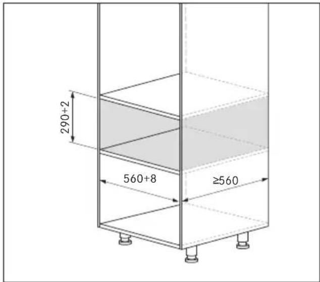
Fig. 9.2 MS290/MSS290 installation dimensions
MS140/MSS140
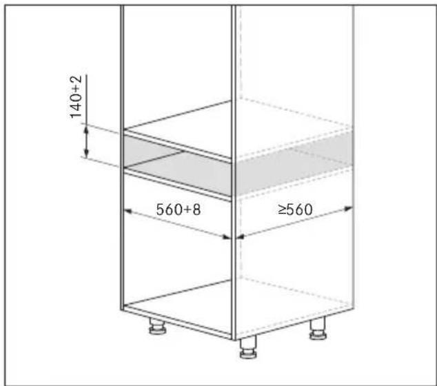
Fig. 9.3 MS140/MSS140 installation dimensions
9.3.3 Multi-drawer fitted unit + X BO steam oven
The X BO assembly instructions must be observed here.
MS290/MSS290 + X BO
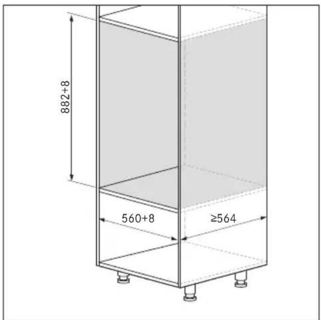
Fig. 9.4 MS290/MSS290 + X BO installation dimensions
MS140/MSS140 + X BO
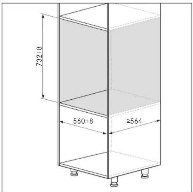
Fig. 9.5 MS140/ MSS140 + X BO installation dimensions
▶ Prepare the fitted unit taking into account the dimensions specified.
Remove the back panel of the unit to the rear of the installation recess.
9.4 Installing the appliance
To ensure that the Push2Open mechanism works correctly, there must be at least 3 mm of clearance between the unit and the panel.
Working with the installation jig
The installation jig provided is used to position the mounting angle in the unit, allowing for a clearance of 3 mm between the unit and the panel for the Push2Open mechanism. The installation jig enables the mounting angle to be fitted in 2 different positions:
- Position 1: drawer with unit front
- Position 2: drawer with multi-drawer glass front, flush to the front in the case of an 18–20 mm thick unit front
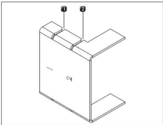
Fig. 9.6 Installation jig
[1] Installation position 1 for unit front
[2] Installation position 2 for glass front
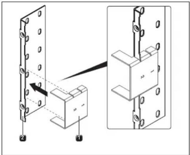
Fig. 9.7 Using the installation jig
[1] Installation jig
[2] Mounting angle
▶ Select the appropriate installation position.
▶ Slot the installation jig onto the mounting angle.
Attaching the mounting angle
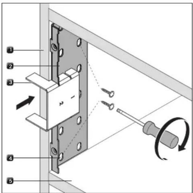
Fig. 9.8 Attaching the mounting angle
[1] Unit
[2] Mounting angle (1 x right, 1 x left)
[3] Installation jig
[4] Screw hole
[5] Construction base
▶ Attach the installation jig [3] and mounting angle [2] to the unit [1].
▶ Position the mounting angle [2] in the unit [1] with the help of the installation jig [3].
- The mounting angle [2] must be surface mounted on the construction base [5]
▶ Select 2 suitable screw holes [4] on the mounting angle [2].
▶ Screw the mounting angle [2] into place with two silver 4 x 16, TX20 screws (included in the scope of delivery).
▶ Repeat these steps on the other side with the second mounting angle.
Connecting the connection cables to the appliance

When installing the appliance, please note that the connection cables will need to be connected to the appliance before installation as the back of the appliance will no longer be accessible once installed (single installation).

However, the appliance must not be connected to the mains before installation is complete.
▶ Connect the mains supply cable to the back of the appliance.
▶ Where applicable, connect the communication cable to the back of the appliance (only if used with the X BO steam oven).
▶ Do not connect the appliance to the mains.
Installing the appliance
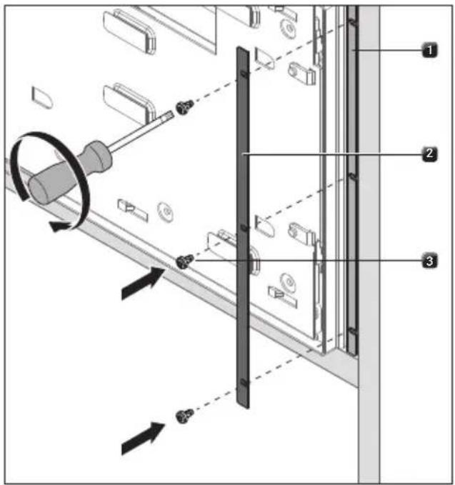
Fig. 9.9 Securing the appliance
[1] Mounting angle (1 x right, 1 x left)
[2] Decorative trim (1 x right, 1 x left)
[3] Black M4 x 8, TX20 screws (3 x right, 3 x left)
▶ Insert the appliance in the installation recess.
▶ Align the appliance in the centre of the installation recess.
▶ Select decorative trim [2] of an appropriate width.
▶ Attach the appliance and decorative trim [2] to the mounting angles [1] on each side with three black M4 x 8, TX20 screws [3] (included in the scope of delivery) (torque: 2.2 Nm ±10%).
9.5 Fitting the front
If the multi-drawer is installed with a X BO steam oven, the X BO must be installed before fitting the front.
When fitting the front, two different procedures must be taken into account:
• fitting the unit front
• fitting the multi-drawer glass front
9.5.1 Fitting the unit front
Positioning the unit front
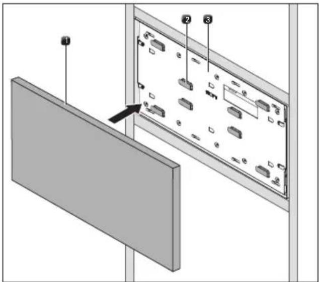
Fig. 9.10 Adhesive pads on the front support
[1] Unit front
[2] Adhesive pads
[3] Front support
Remove the protective strips from the adhesive pads [2] on the front support [3].
▶ With the drawer installed and closed, position the unit front [1] correctly on the front support.
▶ Please observe the clearance when doing so.
▶ Press lightly on the unit front [1].
- The unit front will stick to the front support.
To correct the position, the unit front can be removed by cutting the adhesive pads from the sides.
This adhesive seal is only temporary and may become unstuck in time. Therefore, the front must be screwed into place.
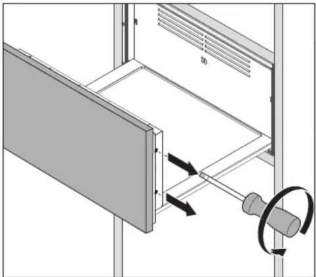
Removing the front support
natural_image
Technical diagram showing a mechanical assembly with a rotating component and directional arrows indicating motion (no text or symbols present)Fig. 9.11 Removing the front support
▶ Open the drawer.
Remove the two screws on the left and right-hand side of the front support.
▶ Push the front support and unit front up until it can be removed from the retaining lugs.
Securing the unit front
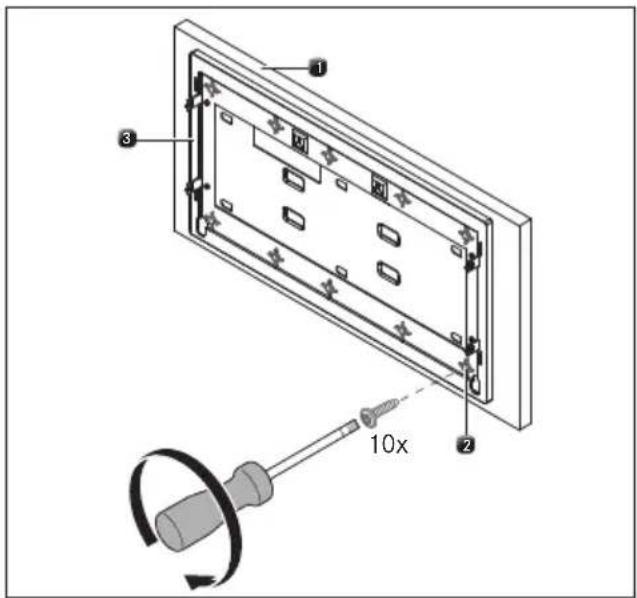
Fig. 9.12 Securing the unit front
[1] Unit front
[2] Screw guides (x 10)
[3] Front support
▶ Using ten silver 4 x 16, TX20 screws (included in the scope of delivery), screw the unit front [1] to the front support [3].
▶ To do this, use the 10 screw guides [2] on the front support [3].
▶ Check the length of the screws before you start. If necessary, replace them with shorter screws of the same kind.
Fitting the front support
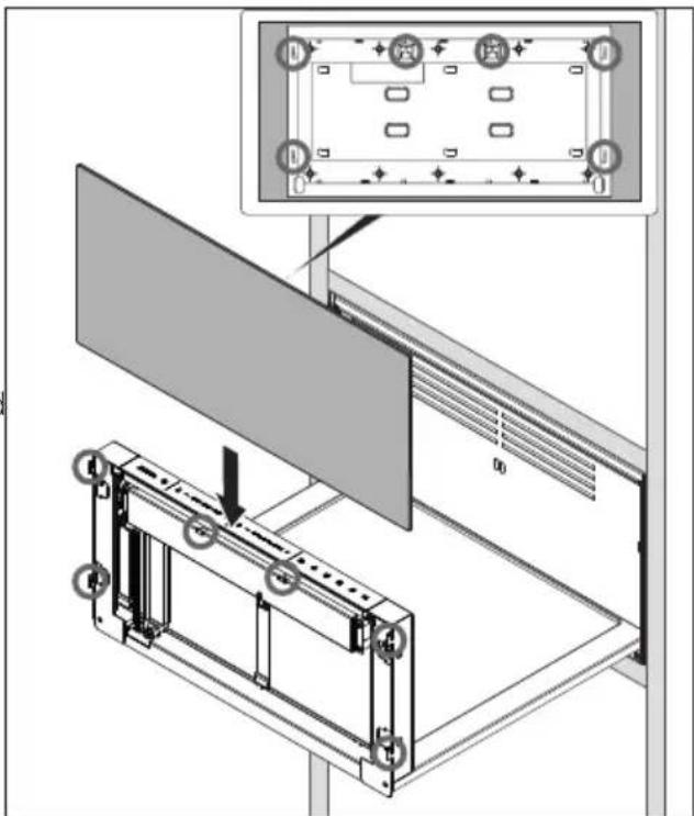
Fig. 9.13 Fitting the front support
▶ Slide the front support and front onto the lugs from above.
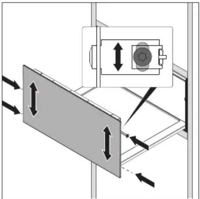
Horizontal adjustment of the front
The front fastenings enable the horizontal clearance to be adjusted after fitting (top and bottom).
natural_image
Diagram showing airflow or movement between two panels with directional arrows and a device component (no text or symbols)Fig. 9.14 Adjusting the horizontal clearance
▶ Insert the two screws on the left and right-hand side of the front support but do not tighten.
▶ Close the drawer.
Even out any visual differences in the clearance.
▶ To do this, slide the front panel to the correct position using your hands.
▶ Open the drawer and tighten the screws on the sides (torque: 1.8 Nm ±10%).
If not screwed in correctly, the front can become loose and fall off. Ensure that all screws are used and are tightened accordingly.
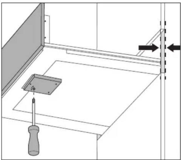
Adjusting the depth of the front
The opening mechanism can be used to move the front forwards or backwards (up to 3 mm).
natural_image
Technical diagram showing a screwdriver inserted into a flatboard assembly with a bracket and wall-mounted fixture (no text or symbols)Fig. 9.15 Adjusting the depth of the front
▶ Adjust the depth of the front.
▶ To do this, turn the mechanism on the bottom of the drawer using a 5 mm Allen key.
9.5.2 Fitting the glass front (MSF290/MSF140)
If the multi-drawer is installed with a X BO steam oven, the multi-drawer glass front can only be fitted after installing the X BO.
To fit the glass front, do not under any circumstances remove the protective strips from the adhesive pads on the front support. The glass front is only to be attached with screws.
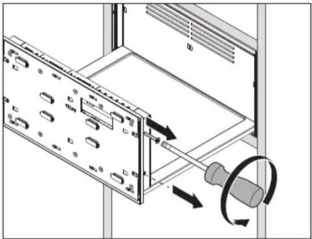
Removing the front support
natural_image
Diagram of a server rack with a USB cable inserted, showing ports and scroll wheel (no text or symbols)Fig. 9.16 Removing the front support
▶ Open the drawer.
Remove the two screws on the left and right-hand side of the front support.
of the retaining lugs.
▶ Push the front support up until it can be taken out9.5.3 Completing installation
Securing the glass front
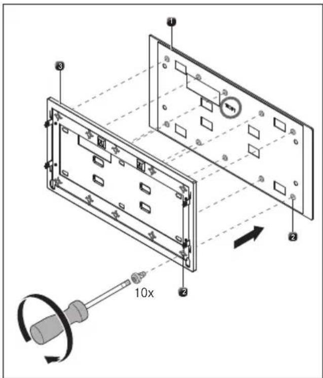
Fig. 9.17 Securing the glass front
[1] Back of the multi-drawer glass front
[2] Screw guides [x 10]
[3] Front support
▶ Lay the glass front face down on a soft surface.
▶ Be careful not to scratch the glass front in doing so.
▶ Position the front support [3] on the back of the multi-drawer glass front [1] so that the 10 screw guides [2] are aligned.
Using a screwdriver, attach the glass front to the 10 screw guides [2] on the front support [3]. Do not use a battery-operated screwdriver to do this or the screws could be overtightened (torque: 1.8 Nm ±10%).
▶ Only use the screws (DIN 7500 C M4 x 6 mm) provided with the multi-drawer glass front. The use of other screws may cause the glass front to break. This poses a risk of injury.
▶ Follow the installation steps under "Fitting the front support" (see „9.5.1 Fitting the unit front“).
t9.5.3 Completing installation
▶ Connect the appliance to the mains.
▶ If necessary, connect the communication cable to the X BO steam oven.
Place the shelf rack in the drawer (only with MS290/MSS290).
▶ Remove the protective film from the operating panel.
Fitting the sealing lip (optional)
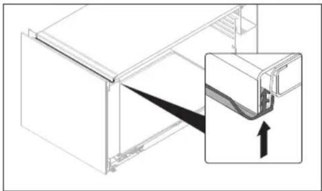
i Particularly where condensation forms, or if a fragile unit front or sensitive appliance is installed above the multi-drawer, we recommend fitting the sealing lip included in the scope of delivery.
The sealing lip must be fitted when the drawer is installed together with the X BO steam oven.
natural_image
Technical line drawing of a mechanical assembly with an inset showing a close-up of a component (no text or symbols present)Fig. 9.18 Fitting the sealing lip
▶ Open the drawer.
▶ Clean the housing frame and the sealing lip.
▶ Guide the sealing lip into the gap at the front from bottom to top and press the sealing lip evenly along its length.
▶ Ensure that the sealing lip is not stretched during installation.
▶ Check that it is positioned correctly.
9.6 Function test
Carry out a thorough function test on the appliance.
In the event of error messages, see the "Troubleshooting" chapter.
9.7 Handover to user
Once installation is complete:
Explain the main functions to the user.
Explain all safety-related aspects of operation and handling to the user.
▶ Provide the user with the accessories and operating and installation instructions to be kept in a safe place.
10 Decommissioning, disassembly and disposal
▶ Observe all safety and warning information (see „2 Safety“).
Follow the enclosed manufacturer's information.
10.1 Decommissioning
Decommissioning is understood as final shutdown and disassembly. Following decommissioning, the device can either be installed into other units, sold on privately or disposed of.
▶ To decommission, switch the device off (see „5 Functions and operation“).
▶ Disconnect the device from the power supply.
10.2 Disassembly
For removal, the device must be accessible for disassembly and disconnected from the power supply.
▶ Disassemble the appliance.
▶ Remove any other accessories.
▶ Dispose of the old device and any contaminated accessories as described under “Environmentally-friendly disposal”.
10.3 Environmentally-friendly disposal
Disposal of transport packaging
The packaging protects the device from damage in transport. The packaging materials have been selected from environmental and disposal perspectives and are therefore recyclable.
Returning the packaging to the materials cycle saves resources and reduces waste volumes. Your specialist supplier will take the packaging back.
▶ Give the packaging to your specialist supplier or
▶ Dispose of the packaging properly in line with local regulations.
Disposal of old appliance
natural_image
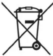
Simple line drawing of a trash bin with two crossed lines indicating no waste or restriction (no text or symbols)Electrical devices marked with this label may not be disposed of in domestic waste at the end of their service life. They must be disposed of at a collection point for the recycling of old electrical or electronic devices. You can find information from your city or district council.
Many electrical and electronic devices still contain valuable materials. But they also contain damaging materials which were necessary for them to function properly and safely. These can damage human health or the environment if disposed of improperly or incorrectly handled.
▶ Never put your old appliance in domestic waste.
▶ Take the old appliance to a regional collection point for return and recycling electrical and electronic components and other materials.
11 Warranty, technical service, spare parts, accessories
▶ Observe all safety and warning information (see “2 Safety”).
11.1 BORA manufacturer's warranty
BORA provides its end customers with a 2-year manufacturer's warranty for its products. The end customer is entitled to this warranty in addition to the statutory claims for defects against the sellers of our products.
The manufacturer's warranty applies to the BORA products listed here that are sold by authorised BORA retailers or salespeople trained by BORA and are installed in the European Union (excluding overseas territories), Switzerland, Liechtenstein, Ukraine, Russia, Norway, Serbia, Israel, the UK, Iceland, India, Australia and New Zealand, with the exception of products referred to by BORA as universal products or accessories:
BORA X BO steam oven
BORA multi-drawers
The manufacturer's warranty starts as soon as the BORA product is handed over to the end customer and is valid for 2 years. Registering on www.mybora.com enables the manufacturer's warranty to be extended to 3 years.
The manufacturer's warranty requires expert installation of the BORA products by an authorised BORA retailer (in accordance with the valid BORA ventilation handbook and operating instructions at the time of installation). During use, the end customer is to adhere to the specifications and instructions in the operating manual.
When filing a warranty claim, BORA must be directly notified of the fault and the receipt must be presented. Alternatively, proof of purchase can be provided by registering on www.mybora.com.
BORA guarantees that all BORA products are free from material and production defects. The defect must exist prior to delivery of the product to the end customer. Filing a warranty claim does not interrupt the warranty period, nor shall the period start anew. BORA will correct defects in BORA products at its own discretion by repairing or replacing the product. All costs for the correction of defects under the manufacturer's warranty shall be assumed by BORA. Expressly not covered by the BORA manufacturer's warranty are:
● BORA products that were not sold by authorised BORA retailers or salespersons trained by BORA
- Damage caused by non-adherence to the operating instructions (including product care and cleaning). This represents improper use.
• Damage caused by normal use,
- Damage caused by external influences (such as transport damage, improper removal and installation, ingress of condensation, damage caused by the elements such as a lightning strike)
- Damage caused by repairs carried out by the owner, repairs or attempts to repair carried out by unauthorised BORA staff or companies not authorised by BORA
- Damage caused by water or dirt due to missing covers or elements
- Damage caused by water placed inside the oven chamber
- Damage caused by extending the water supply and drainage hose without drinking water certification or by extending non-specified pipes with an adapter
- Damage to
- plastic frames
- glass components
- metal components (coated and uncoated)
- touch display
- plastic and other wearable parts
● Damage caused by electrical voltage fluctuations
- Secondary damage or claims for damages beyond the defect
Legal claims, particularly statutory claims for defects or product liability are not limited by the warranty and can be asserted free of charge.
If a defect is not covered by the manufacturer's warranty, a claim may be made against the BORA Technical Service.
BORA shall not assume the resulting costs.
The laws of the Federal Republic of Germany apply to these warranty conditions.
You can contact us at:
Monday to Thursday from 08:00–18:00 and Friday from 08:00–17:00
- Email: support@bora.com
11.2 Service
BORA Service:
see reverse side of the operating and assembly instructions

00800 7890 0987
In the case of faults you cannot fix yourself, contact your BORA specialised retailer or the BORA Service Team.
The BORA Service Team will require the type designation and serial number of your appliance (FD number).
You can find both details inside the drawer.
- Multi-drawer mains supply cable type G (UK, IE) MSNLG
- Multi-drawer mains supply cable type I (AU) MSNLI
Special accessory for MS290:
• Multi-drawer shelf rack MSER
11.3 Spare parts
▶ Only use original spare parts for repairs.
▶ Repairs may only be carried out by the BORA Service Team.
i Spare parts can be obtained from your BORA dealer, the BORA online service website at www.bora.com/service or by calling the service number provided.
11.4 Accessories
- Multi-drawer glass front 140 mm MSF140
- Multi-drawer glass front 290 mm MSF290
- Multi-drawer mains supply cable type J (CH) MSNLJ
Operating and installation instructions:
○ Original
- Translation
The distribution and duplication of this document, as well as the use and disclosure of its contents are prohibited unless expressly authorised.
These operating and installation instructions have been drawn up with the greatest of care. But it cannot be ruled out that subsequent technical modifications have not yet been incorporated or the relevant content has not yet been adapted. Please accept our apologies in this eventuality. An updated version can be requested from the BORA Service Team. Subject to printing errors and mistakes.
info@boraapac.com.au
bora-australia.com.au

00800 7890 0987
- EN MS290/MS140, MSS290/MSS140 operating and installation instructions
- Table of Contents
- General information 49
- Safety 51
- Technical data 59
- Appliance description 62
- Functions and operation 65
- Applications 70
- Cleaning and maintenance 72
- Troubleshooting 73
- Installation 74
- Decommissioning, disassembly and disposal83
- Warranty, technical service, spare parts, accessories 84
- General information
- Liability
- Validity of the operating and installation instructions
- Product conformity
- Directives
- Presentation of information
- Safety and warning instructions
- WARNING SYMBOL AND SIGNAL WORD!
- Type and source of danger
- Results of non-compliance Measures to minimise risk
- Please note:
- Warning symbol Signal word Risk
- Danger Indicates an
- Figures
- Safety
- Use as intended
- This appliance is not intended for:
- People with limited abilities
- Children
- People with reduced physical, sensory or mental capacities
- General safety instructions
- ANGER!
- Packaging components are a choking hazard
- Risk of electric shock or injury from damaged surfaces
- WARNING!
- Risk of injury or damage due to incorrect components or unauthorised modifications
- Risk of injury due to mechanical damage on the appliance
- CAUTION!
- Appliance components can cause injury if dropped
- Risk of injury from heavy lifting
- Damage from improper use
- Faults and errors
- Pets
- Safety instructions for installation
- Risk of electric shock from damaged appliance
- DANGER!
- Risk of electric shock from damaged power supply cable
- Safety instructions – operation
- Risk of burns from hot surfaces.
- Risk of burns due to power cut
- Risk of fire from overheated oil or fat
- Risk of fire from overdrying
- Risk of burning and fire from hot objects
- Risk of burns or explosion caused by flammable liquids
- Risk of injury from moving appliance parts
- Risk of injury from open door/drawer
- Damage caused by opening the drawer brusquely
- Safety instructions – cleaning and maintenance
- Risk of corrosion
- Safety instructions – repairs, servicing and spare parts
- Risk of injury or damage from improper repairs
- Safety instructions – disassembly and disposal
- Technical data
- Appliance description
- Appliance features
- Model description
- Structure
- How it works
- Touch operating panel
- Indicator symbols
- Control symbols
- LED oven chamber lighting
- Shelf rack
- Functions and operation
- Opening and closing the drawer
- Touch control
- Command Contact Time
- Initial operation
- Load capacity
- Examples of load capacity for crockery
- Load capacity Crockery MS140 MS290
- Tab. 5.2 Examples of load capacity
- Switching on and off
- Switching on
- Switching off
- Manual operation
- Setting the temperature and time
- Start the appliance
- The time has lapsed
- Permanently changing standard settings
- Using preset programmes
- Preset programmes
- Warming crockery
- Reheating food
- Keeping food warm
- Defrosting food
- Low-temperature cooking
- Example of use: meat
- Preparation
- Cooking
- Using preset programmes
- Selecting a programme
- Modifying programmes
- Starting the programme
- End of programme
- Delayed start
- Activating the delayed start
- Standby mode
- BORA Connectivity
- Demo mode
- Activating/deactivating the demo mode
- Factory settings
- Resetting the appliance to factory settings
- Applications
- Cleaning and maintenance
- Cleaning agents
- Cleaning the exterior
- Cleaning the cooking chamber
- Troubleshooting
- Installation
- Scope of delivery
- Tools and aids
- Assembly instructions
- Possible appliance combinations
- Fitted unit (single installation)
- Multi-drawer fitted unit + X BO steam oven
- Installing the appliance
- Working with the installation jig
- Connecting the connection cables to the appliance
- Fitting the front
- Fitting the unit front
- Removing the front support
- Securing the unit front
- Fitting the front support
- Horizontal adjustment of the front
- Adjusting the depth of the front
- Fitting the glass front (MSF290/MSF140)
- t9.5.3 Completing installation
- Fitting the sealing lip (optional)
- Function test
- Handover to user
- Decommissioning, disassembly and disposal
- Decommissioning
- Disassembly
- Environmentally-friendly disposal
- Disposal of old appliance
- Warranty, technical service, spare parts, accessories
- BORA manufacturer's warranty
- Service
- BORA Service:
- 7890 0987
- Special accessory for MS290:
- Spare parts
- Accessories
Brand : BORA
Model : MSS140
Category : Warming Drawer