CMMB-AS-02 - Regulator Festo - Free user manual and instructions
Find the device manual for free CMMB-AS-02 Festo in PDF.


| Product Type | Motor Controller for AC Servo Motors |
| Model | CMMB-AS-02 |
| Rated Power | 200 W |
| Power Supply (Drive) | Single phase 200-240 VAC ±10%, 50/60 Hz, 3 A |
| Power Supply (Control) | Single phase 200-240 VAC ±10%, 50/60 Hz, 0.5 A |
| DC Bus Voltage | Internal DC+ / DC- (max. from rectified input) |
| Control Modes | Velocity, Torque, Position, Pulse Train, Homing, Jog |
| Communication Interface | RS232 (X3), 38400 bps default, configurable |
| Digital Inputs | 7 configurable, 12.5-30 VDC active |
| Digital Outputs | 5 configurable, max 100 mA (OUT1/2), 20 mA (OUT3-5) |
| Analog Inputs | 2 differential, ±10 V, 12 bit, 1 kHz bandwidth |
| Encoder Feedback | 20-bit single-turn absolute encoder (EMMB motors) |
| Pulse Command Input | CW/CCW, P/D, or A/B, max 500 kHz |
| Protection Degree | IP20 |
| Operating Temperature | 0 to 40 °C |
| Storage Temperature | -10 to 70 °C |
| Humidity | 5 to 95% RH (non-condensing) |
| Altitude | Up to 2000 m (derating above 1000 m) |
| Vibration Resistance | ≤5.9 m/s² at 10-60 Hz |
| Cooling | Natural convection (no fan for this model) |
| Certifications | UL listed (US and Canada), CE |
| Intended Use | Industrial control cabinets, regulation of torque, speed, and position |
| Setup Methods | LED panel with Easy Use and tunE menus, PC software CMMB Configurator |
| Compatible Motor Series | Festo EMMB-AS (100-750 W) |
Frequently Asked Questions - CMMB-AS-02 Festo
User questions about CMMB-AS-02 Festo
0 question about this device. Answer the ones you know or ask your own.
Ask a new question about this device
Download the instructions for your Regulator in PDF format for free! Find your manual CMMB-AS-02 - Festo and take your electronic device back in hand. On this page are published all the documents necessary for the use of your device. CMMB-AS-02 by Festo.
USER MANUAL CMMB-AS-02 Festo
natural_image
Line drawing of an FESTO PLC internal unit with ventilation grilles and connector ports (no text or symbols on the device itself)Description
Mounting and installation
For motor controller CMMB-AS-0x
8189115
2023-01c
[8189117]
Identification of hazards and instructions on how to prevent them:

Danger
Immediate dangers which can lead to death or serious injuries

Warning
Hazards that can cause death or serious injuries

Caution
Hazards that can cause minor injuries or serious damage to property
Other symbols:

Note
Material damage or loss of function

Recommendations, tips, references to other documentation

Essential or useful accessories

Information on environmentally sound use
Text designations:
• Activities that may be carried out in any order
- Activities that should be carried out in the order stated
- General lists
→ Result of an action / references to more detailed information
Revisions history
| Version | Chapter | Date | Change |
| 1.00 | All | 2017-03-17 | First release |
| 1.01 | 3.2.4, 6.2.1, 6.3.1 | 2017-05-09 | Figure 3-5, tables 6-7, 6-11 |
| 1.02 | 3.1.1, 3.2.2 | 2017-07-18 | Table 3-1, Table 3-2 |
| 1.03 | 6.4.1 | 2017-10-25 | Figure 6-2, text |
| 1.04 | 2.1 | 2020-04-13 | Figure 2-2, tables 2-2, 2-3, 2-4. |
| 3.2.4 | 2020-04-13 | Table 3-4: Definition of X4, figure 3-5 | |
| 4.3.2 | 2020-04-13 | Table 4-2: EASY menu parameters | |
| 6.1 | 2020-04-13 | Table 6-2 | |
| 9.4 | 2020-04-13 | Added description for d4.01 | |
| 9.5 | 2020-04-13 | Table 9-5 | |
| Chapter 11 | 2020-04-13 | New Chapter | |
| 1.05 | 10.2 | 2021-02-23 | Updated the Node ID Added a negative sign as - |
| 6.1 | 2022-11-25 | Table 6-2 |
Contents
Chapter 1 Safety and requirements for product use ....1
1.1 Safety....1
1.1.1 Safety instructions for commissioning, repair and de-commissioning .... 1
1.1.2 Protection against electric shock through protective extra-low voltage (PELV)....1
1.1.3 Intended use 2
1.2 Requirements for product use....2
1.2.1 Transport and storage conditions 2
1.2.2 Technical requirements....2
1.2.3 Qualification of the specialists (requirements for personnel) 3
1.2.4 Range of application and certifications .... 3
Chapter 2 Introduction....3
2.1 Product overview .... 3
2.1.1 CMMB Motor controller .... 3
2.1.2 EMMB Servo motor 4
2.1.3 NEBM cables....4
2.2 Device view....7
Chapter 3 Installation of the CMMB motor controller ....8
3.1 Mechanical installation 8
3.1.1 Environment requirements....8
3.1.2 Mounting conditions....8
3.2 Electrical installation 9
3.2.1 Front view of CMMB series motor controller....9
3.2.2 Power connector (X2)....10
3.2.3 RS232 port (X3) 10
3.2.4 Multi-function connector (X4) 11
3.2.5 Encoder input (X5) 13
3.3 Wiring of the CMMB servo system....13
3.3.1 Selection of fuses, braking resistors and circuit breakers 14
Chapter 4 Controller setup with LED panel ....15
4.1 Panel operation.... 15
4.2 Panel menu structure and navigation 16
4.3 Easy Use function 17
4.3.1 Setup process with Easy Use function 17
4.3.2 Flowchart and description of the EASY menu 18
4.3.3 Flowchart and description of the tunE menu 24
4.3.4 Jog mode (F006) 27
4.3.5 Error History (F007) 27
Chapter 5 CMMB configurator, user guide....29
5.1 Getting started 29
5.1.1 Language 29
5.1.2 Opening and saving project files 29
5.1.3 Starting communication.... 30
5.1.4 Node ID and baud rate....30
5.1.5 Objects (add, delete, help) 30
5.2 Init save reboot 31
5.3 Firmware update .... 31
5.4 Read/write controller configuration 32
5.4.1 Read settings from controller 32
5.4.2 Write settings to controller 32
5.5 Digital IO functions....33
5.5.1 Digital inputs 34
5.5.2 Digital outputs 36
5.5.3 Gear ratio switch (expert only).... 37
5.5.4 Gain switch (expert only)....38
5.5.5 Fast Capture 40
5.6 Scope 41
5.7 Error display and error history 42
Chapter 6 Operation modes and control modes....45
6.1 General steps for starting a control mode.... 45
6.2 Velocity mode (-3, 3) 48
6.2.1 Analog speed mode 48
6.2.2 DIN speed mode....50
6.3 Torque mode (4)....51
6.3.1 Analog torque mode....51
6.4 Position mode (1) 52
6.4.1 Position Table mode 52
6.5 Pulse Train mode (-4).... 57
6.5.1 Master-slave mode....58
6.6 Homing mode (6) 58
Chapter 7 Tuning of the servo system control....68
7.1 Auto-tuning 68
7.1.1 Parameters for auto-tuning....69
7.1.2 Start of auto-tuning....69
7.1.3 Problems with auto-tuning....70
7.1.4 Adjustment after auto-tuning....70
7.2 Manual tuning....71
7.2.1 Tuning of the velocity loop....71
7.2.2 Tuning of the position loop 73
7.3 Factors which influence tuning results 75
Chapter 8 Alarms and troubleshooting....76
Chapter 9 List of CMMB series motor controller parameters....78
9.1 F001 78
9.2 F002 79
9.3 F003 81
9.4 F004 84
9.5 F005 85
Chapter 10 Communication ....86
10.1 RS232 wiring 86
10.1.1 Point to point connection 86
10.1.2 Multi-point connection....86
10.2 Transport protocol....86
10.2.1 Point to point protocol 87
10.2.2 Multi-point protocol 87
10.3 Data protocol....87
10.3.1 Download (from host to slave) 88
10.3.2 Upload (from slave to host) 88
10.4 RS232 telegram example....89
Chapter 11 Appendix ......90
11.1 Multi-Turn Encoders supported by CMMB....90
11.1.1 Hardware requirements....90
11.1.2 Application scenarios....90
11.1.3 Warning and Error....90
11.1.4 Absolute position definition....91
Chapter 1 Safety and requirements for product use
1.1 Safety
1.1.1 Safety instructions for commissioning, repair and de-commissioning

Warning
Danger of electric shock
- If cables are not mounted to the plug X2.
- If connecting cables are disconnected when energised.
Touching live parts causes severe injuries and may lead to death.
The product may only be operated in the installed state and when all safeguards have been initiated.
Before touching live parts during maintenance, repair and cleaning work, and after been long service interruptions:
Switch off power to the electrical equipment via the mains switch and secure it against being switched on again.
After switching off, allow to discharge for at least 10 minutes and check that power is turned off before accessing the controller. Make sure that the charge lamp on the front of the controller is off.

Note
Danger from unexpected movement of the motor or axis
- Make sure that motion does not endanger anyone.
- Perform a risk assessment in accordance with the EC machinery directive.
- Based on this risk assessment, design the safety system for the entire machine, taking into account all integrated components. This also includes the electric drives.
- Bypassing safety equipment is impermissible.
1.1.2 Protection against electric shock through protective extra-low voltage (PELV)

Warning
- Use only PELV circuits in accordance with IEC/EN 60204-1 (protective extra-low voltage, PELV) for electrical power supply. Also comply with the general requirements for PELV circuits specified in IEC/EN 60204-1.
- Use only power sources which guarantee reliable electrical disconnection of the operating voltage as per IEC/EN 60204-1.
Protection against electric shock (protection against direct and indirect contact) is ensured in accordance with IEC/EN 60204-1 through the use of PELV circuits (Electrical equipment of machines, general requirements).
1.1.3 Intended use
The CMMB-AS-0x is intended for
- Use in control cabinets for power supply to AC servo motors and regulation of torques (current), rotational speed and position.
The CMMB-AS-0x is intended for installation in machines or automated systems and may only be used:
- When in excellent technical condition
– In original condition without unauthorised modification
– Within the limits of the product defined by the technical data
– In an industrial environment
The product is intended for use in industrial areas. When used outside an industrial environment, e.g. in commercial and mixed residential areas, measures for radio interference suppression may be necessary.

Note
In the event of damage caused by unauthorised manipulation or other than intended use, the guarantee is rendered null and void and the manufacturer is not liable for damages.
1.2 Requirements for product use
● Make this documentation available to the design engineer, installer and personnel responsible for commissioning the machine or system in which this product is used.
- Make sure that the specifications of the documentation are always complied with. Also consider the documentation for the other components and modules.
Take legal regulations applicable at the destination into consideration, as well as:
- Regulations and standards
– Regulations of testing organizations and insurers - National specifications
1.2.1 Transport and storage conditions
- Protect the product during transport and storage from impermissible loads such as:
- Mechanical load
- Impermissible temperatures
- Moisture
- Aggressive atmospheres
- Store and transport the product in its original packaging. The original packaging offers sufficient protection from typical stressing.
1.2.2 Technical requirements
General conditions for correct and safe use of the product, which must be observed at all times:
- Comply with the connection and environmental conditions specified in the technical data of the product and of all connected components.
Compliance with limit values and load limits is mandatory in order to assure operation of the product in accordance with the relevant safety regulations.
- Observe the instructions and warnings in this documentation.
1.2.3 Qualification of the specialists (requirements for personnel)
The product may only be placed in operation by a qualified electrician who is familiar with:
- Installation and operation of electrical control systems
- Applicable regulations for operating safety-engineered systems
– Applicable regulations for accident protection and occupational safety - Documentation for the product
1.2.4 Range of application and certifications

Certificates and declaration of conformity for this product can be found at www.festo.com/sp.
The product has been certified by Underwriters Laboratories Inc. (UL) for the USA and Canada and is marked as follows:

US LISTED
UL listing mark for Canada and the United States
Chapter 2 Introduction
2.1 Product overview
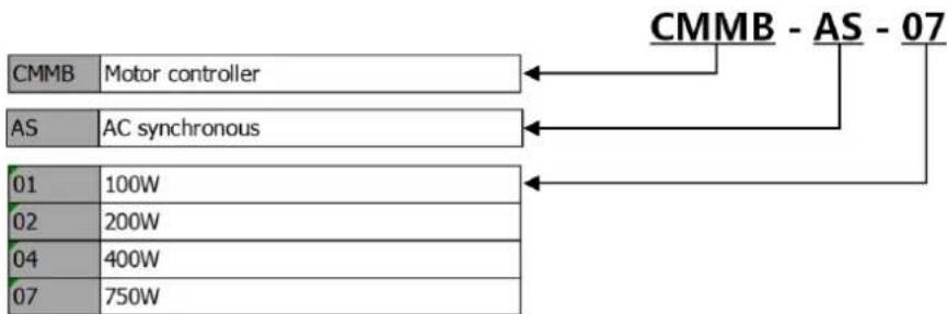
The CMMB motor controller series consists of four models of motor controllers for four different power ratings. Together with the EMMB servo motor series, the CMMB series provides a pulse train servo system platform with a rated power range of 100 to 750 W.
2.1.1 CMMB Motor controller
The CMMB motor controller is available in the following models:
Table 2-1: Model type
| Model | Power |
| CMMB-AS-01 | 100 W |
| CMMB-AS-02 | 200 W |
| CMMB-AS-04 | 400 W |
| CMMB-AS-07 | 750 W |
flowchart
graph TD
    A["CMMB"] --> B["Motor controller"]
    C["AS"] --> D["AC synchronous"]
    E["01"] --> F["100W"]
    G["02"] --> H["200W"]
    I["04"] --> J["400W"]
    K["07"] --> L["750W"]
    M["CMMB - AS - 07"] --> N
    style A fill:#f9f,stroke:#333
    style C fill:#f9f,stroke:#333
    style E fill:#f9f,stroke:#333
    style G fill:#f9f,stroke:#333
    style I fill:#f9f,stroke:#333
    style K fill:#f9f,stroke:#333
Figure 2-1: Type code motor controller
2.1.2 EMMB Servo motor
The EMMB series of high performance AC servo motors includes motors within a range of 100 to 750W rated power and is a equipped with 20 bit single-turn absolute encoder feedback systems.
| EMMB | - | AS | - | 60 | - | 02 | - | K | - | S | 30 | M | B | |
| Series | ||||||||||||||
| EMMB | Series B | |||||||||||||
| Motor technology | ||||||||||||||
| AS | AC-synchronous | |||||||||||||
| Flange size Motors | ||||||||||||||
| 40 | 40 mm | |||||||||||||
| 60 | 60 mm | |||||||||||||
| 80 | 80 mm | |||||||||||||
| Power class | ||||||||||||||
| 01 | 100 W | |||||||||||||
| 02 | 200 W | |||||||||||||
| 04 | 400 W | |||||||||||||
| 07 | 750 W | |||||||||||||
| Motor shaft | ||||||||||||||
| Smooth shaft | ||||||||||||||
| K | Keyway shaft acc. to DIN 6885 | |||||||||||||
| Electrical connection | ||||||||||||||
| S | Straight plug | |||||||||||||
| Lead length | ||||||||||||||
| 30 | 30 cm | |||||||||||||
| Measuring unit | ||||||||||||||
| S | Encoder absolute, Single-turn | |||||||||||||
| M | Encoder absolute, Multi-turn | |||||||||||||
| Brake | ||||||||||||||
| Without | ||||||||||||||
| B | With Brake | |||||||||||||
Figure 2-2: Servo motor type code
2.1.3 NEBM cables
NEBM cables provide plug and play connectivity between the motor controller and the servo motors, and are available in four different standard lengths.
Table 2-2: Motor cable
| Standard cable | |
| Length (unit: m) Type | |
| 2.5 | NEBM-H6G4-K-2.5-Q13N-LE4 |
| 5 | NEBM-H6G4-K-5-Q13N-LE4 |
| 7.5 | NEBM-H6G4-K-7.5-Q13N-LE4 |
| 10 | NEBM-H6G4-K-10-Q13N-LE4 |
| Flexible cable (useable in cable chain) | |
| Length (unit: m) Type | |
| 2.5 | NEBM-H6G4-E-2.5-Q13N-LE4 |
| 5 | NEBM-H6G4-E-5-Q13N-LE4 |
| 7.5 | NEBM-H6G4-E-7.5-Q13N-LE4 |
| 10 | NEBM-H6G4-E-10-Q13N-LE4 |
| 15 | NEBM-H6G4-E-15-Q13N-LE4 |
| 20 | NEBM-H6G4-E-20-Q13N-LE4 |
| 25 | NEBM-H6G4-E-25-Q13N-LE4 |
Table 2-3: Encoder cable
| Standard cable | |
| Length (unit: m) Type | |
| 2.5 | NEBM-REG6-K-2.5-Q14N-REG6 |
| 5 | NEBM-REG6-K-5-Q14N-REG6 |
| 7.5 | NEBM-REG6-K-7.5-Q14N-REG6 |
| 10 | NEBM-REG6-K-10-Q14N-REG6 |
| Flexible cable (usable in cable chain) | |
| Length (unit: m) | Type |
| 2.5 | NEBM-REG6-E-2.5-Q14N-REG6 |
| 5 | NEBM-REG6-E-5-Q14N-REG6 |
| 7.5 | NEBM-REG6-E-7.5-Q14N-REG6 |
| 10 | NEBM-REG6-E-10-Q14N-REG6 |
| 15 | NEBM-REG6-E-15-Q14N-REG6 |
| 20 | NEBM-REG6-E-20-Q14N-REG6 |
| 25 | NEBM-REG6-E-25-Q14N-REG6 |
Table 2-4: Brake cable
| Standard cable | |
| Length (unit: m) | Type |
| 2.5 | NEBM-H7G2-K-2.5-Q14N-LE2 |
| 5 | NEBM-H7G2-K-5-Q14N-LE2 |
| 7.5 | NEBM-H7G2-K-7.5-Q14N-LE2 |
| 10 | NEBM-H7G2- K-10-Q14N-LE2 |
| Flexible cable (usable in cable chain) | |
| Length (unit: m) Type | |
| 2.5 | NEBM-H7G2-E-2.5-Q14N-LE2 |
| 5 | NEBM-H7G2-E-5-Q14N-LE2 |
| 7.5 | NEBM-H7G2-E-7.5-Q14N-LE2 |
| 10 | NEBM-H7G2-E-10-Q14N-LE2 |
| 15 | NEBM-H7G2-E-15-Q14N-LE2 |
| 20 | NEBM-H7G2-E-20-Q14N-LE2 |
| 25 | NEBM-H7G2-E-25-Q14N-LE2 |
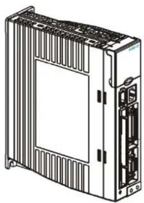
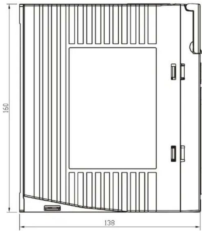
2.2 Device view
natural_image
Line drawing of a server rack unit with ventilation grilles and internal components (no text or symbols)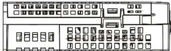
natural_image
Line drawing of a multi-panel electronic device with ports, buttons, and connectors (no text or symbols)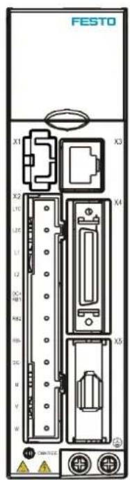
natural_image
Technical line drawing of a rectangular enclosure with internal partitions and dimension annotations (no text or symbols)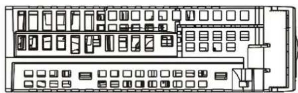
natural_image
Technical line drawing of a multi-panel electronic control panel with no visible text or symbols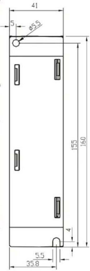
Figure 2-3: Device view
Chapter 3 Installation of the CMMB motor controller
3.1 Mechanical installation
3.1.1 Environment requirements
Table 3-1: Environment requirements
| Environment Requirement | |
| Working temperature | 0 - 40°C (no ice) |
| Working humidity | 5 - 95%RH (no condensation) |
| Storage temperature | -10 - 70°C (no ice) |
| Storage humidity | 5 - 95%RH (no condensation) |
| Assembly requirement | Indoors without sunlight, corrosive gas, non-flammable gas, no dust. |
| Altitude | Less than 2000 m, power derating between 1000m and 2000m |
| Vibration | Less than 5.9m/s ^2 , 10□ 60Hz (not to be used at the resonance point) |
| Degree of protection IP20 |
3.1.2 Mounting conditions
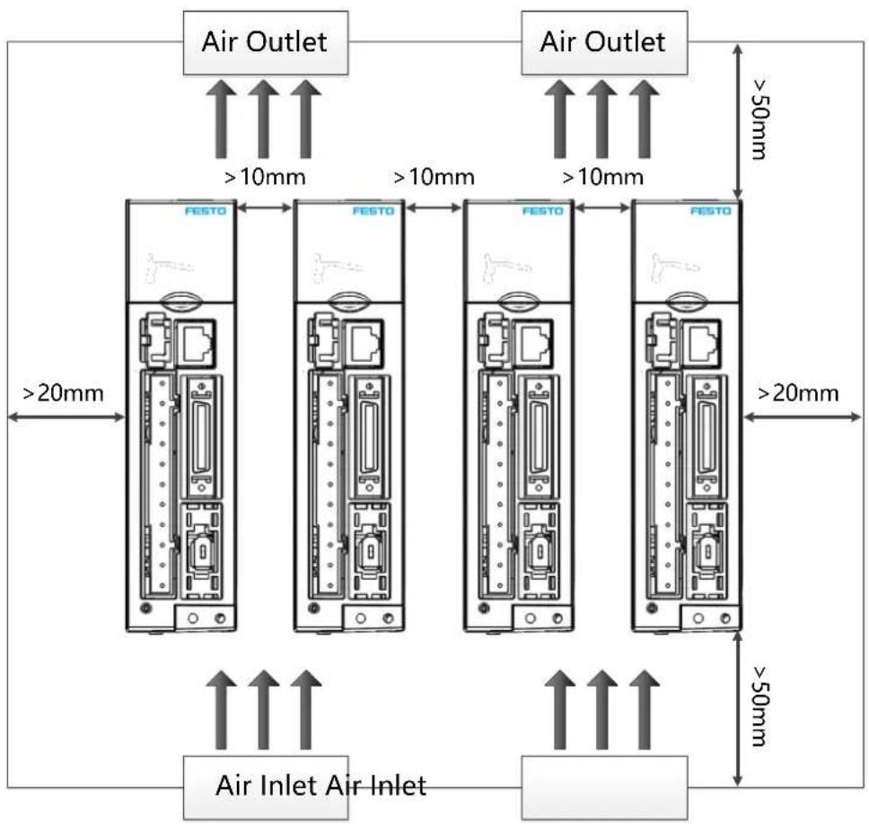
Figure 3-1: Installation orientation, distances and clearances

Note
The motor controller has to be installed in an electrical cabinet which provides a pollution degree 2 environment.
The installation orientation is vertical to provide sufficient convection air flow through the controller housing.
Comply with distances and clearances shown in figure 3-1.
Ensure that the motor controller is securely mounted with two M5 screws.
Do not insert anything into the ventilation openings of the controller.
Do not block the ventilation openings of the controller.
Only use attachments / accessories specified by the manufacturer.
The heat sink in the CMMB-AS-01, CMMB-AS-02 is cooled by natural air convection flow.
The heat sink in the CMMB-AS-04, CMMB-AS-07 is cooled by an internal fan.

Warning
In the case of use of an external brake resistor, provide adequate space around the brake resistor since it can become very hot. No burnable material should touch or be close to the brake resistor. Otherwise there is risk of fire, especially in case of a malfunction of the brake chopper.
3.2 Electrical installation
3.2.1 Front view of CMMB series motor controller
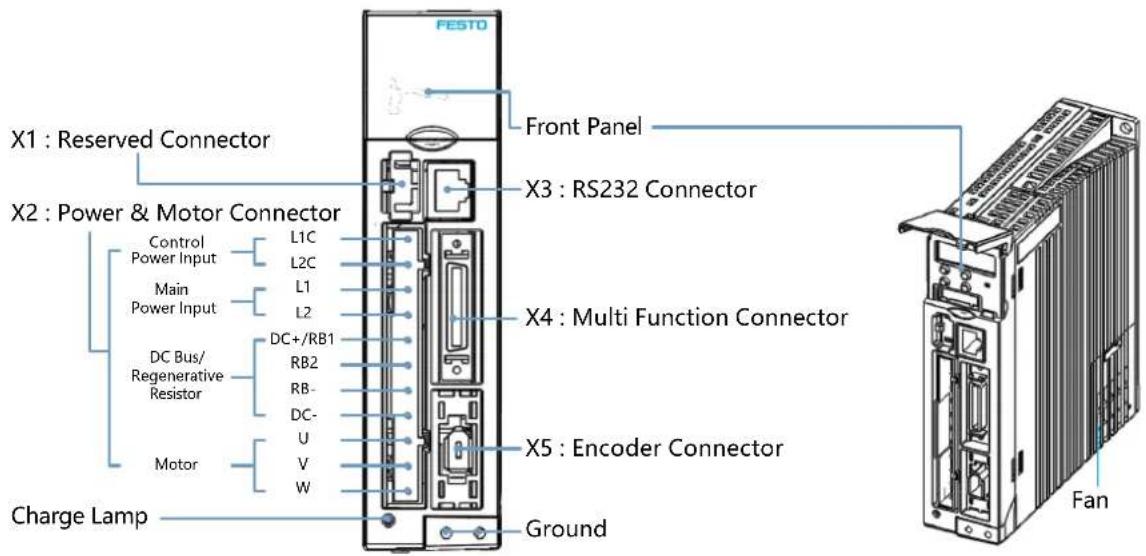
Figure 3-2: Front view
The fan of controller is replaceable. If a fan becomes defective, open the fan cover and replace it with a fan with the same performance ratings. Technical requirements for the fan are as follows:
Power: 12VDC, 0.12A, size: 40 x 40 x 10 mm
3.2.2 Power connector (X2)
Table 3-2: Power connector
| L1C—○L2C—○L1—○L2—○DC+/RB1—○RB2—○RB-—○DC-—○U—○V—○W—○ | Pin Function | |||
| L1C | Control power input L/NSingle phase 200 – 240VAC ±10% 50 / 60Hz, 0.5ASupply earthing systems: TN-S, TN-C, TN-C-S, TT (not corner earthed). | |||
| L2C | ||||
| L1 | Drive power input L/NSingle phase 200 – 240VAC ±10%, 50 / 60Hz750W @7A, 400W @4.5A, 200W @3A, 100W @1.5ASupply earthing systems: TN-S, TN-C, TN-C-S, TT (not corner earthed). | |||
| L2 | ||||
| DC+/RB1 | DC+ DC bus+ | i InformationShort circuit DC+ / RB1 and RB2 if choosing controller internal braking resistor (power: 10 W)→ NoteIt is forbidden to use the internal braking resistor if the average brake power is more than 10 W. | ||
| RB1 | External braking resistor input | |||
| RB2 | Internal braking resistor input | |||
| RB- | External braking resistor input | |||
| DC- DC bus- | ||||
| U/V/W | U/V/W phase power output for servo motor | |||
Wire cross section for all pins:
AWG 22 (0.32 mm ^4 ) to AWG 14 (2.1 mm ^4 )
3.2.3 RS232 port (X3)
Table 3-3: RS232 port
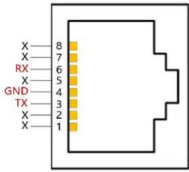 | Pin number | Definition | Function |
| 3 TX Send controller data | |||
| 4 GND Signal ground | |||
| 6 RX Receive controller data | |||
| Others | NC | Reserved | |
3.2.4 Multi-function connector (X4)
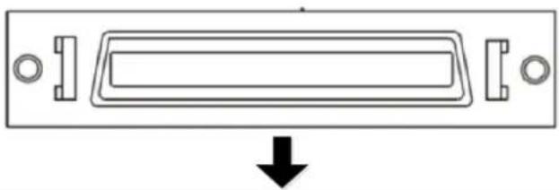
natural_image
Pure diagram of a rectangular device with internal components and a downward arrow, no text or symbols present.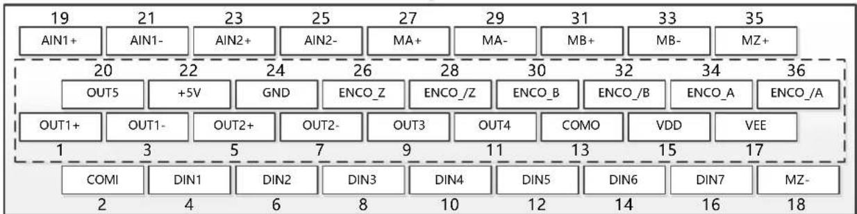
other
| Label | Value | |---|---| | 19 | 19 | | AIN1+ | AIN1+ | | 20 | 20 | | OUT5 | OUT5 | | 21 | 21 | | +5V | +5V | | 22 | 22 | | GND | GND | | 23 | 23 | | OUT1+ | OUT1+ | | 24 | 24 | | OUT2- | OUT2- | | 25 | 25 | | MA+ | MA+ | | 26 | 26 | | 27 | 27 | | 28 | 28 | | 29 | 29 | | 30 | 30 | | 31 | 31 | | MB+ | MB+ | | 32 | 32 | | 33 | 33 | | MB- | MB- | | 34 | 34 | | 35 | 35 | | 36 | 36 | | COMI | COMI | | DIN1 | DIN1 | | 1 | 1 | | 2 | 2 | | 3 | 3 | | OUT1- | OUT1- | | 4 | DIN1 | | 5 | DIN1 | | 6 | DIN2 | | 7 | DIN2 | | 8 | DIN3 | | 9 | DIN3 | | 10 | DIN4 | | 11 | DIN4 | | 12 | DIN5 | | 13 | DIN5 | | 14 | DIN6 | | 15 | DIN6 | | 16 | DIN7 | | 17 | DIN7 | | MZ- | MZ- | | DIN7 | DIN7 | | MZ- | MZ- |Figure 3-3: Multi-function connector
Table 3-4: Definition of X4
| PIN Function | |
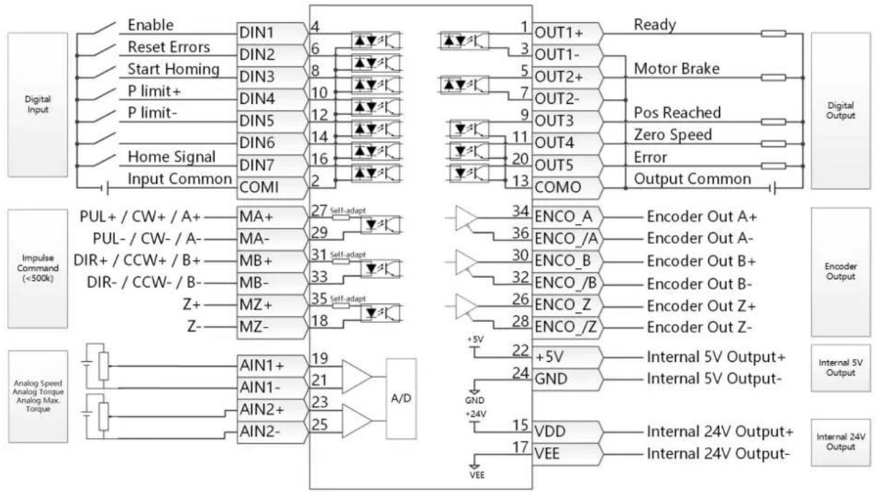
| DIN1-DIN7 | Digital signal inputVinH (active): 12.5VDC-30VDC,VinL (inactive): 0VDC-5VDC,input freq.: <1KHz |
| COMI | Common pin of digital input |
| OUT1+ / OUT1- | Digital signal outputMaximum output current: 100mA |
| OUT2+ / OUT2- | |
| OUT3 / OUT4 / OUT5 | Digital signal outputMaximum output current: 20mA |
| COMO | Common pin of digital output OUT3, 4, 5 |
| MA+ / MA- | Pulse inputInput voltage: 3.3V-24VMaximum frequency: 500KHz |
| MB+ / MB- | |
| MZ+ / MZ- | |
| ENCO_A+ / ENCO_A- | Encoder outputVoltage: Voh=3.4V, Vol=0.2VMaximum current: ±20mA, maximum frequency: 10MHzThe ENCO_Z±signal is always happening when the encoder single turn crossing 0. |
| ENCO_B+ / ENCO_B- | |
| ENCO_Z+ / ENCO_Z- | |
| AIN1+ / AIN1-AIN2+ / AIN2- | Analog inputResolution: 12 bit, input resistance: 350 KΩAnalog bandwidth: 1KHz, input voltage range: -10V +10V |
| +5V / GND | 5VDC power supply outputMaximum current: 100mA |
| VDD/VEE | 24VDC power supply outputVoltage range: 24VDC ± 20%, maximum current: 300 mA |
The following figure shows the wiring of X4 with default IO function. More IO functions can be defined with the digital panel or PC software. Please refer to chapter 5.5 for more details regarding IO functions.
flowchart
graph TD
    subgraph Digital Input
        A["Enable"] --> B["DIN1"]
        C["Reset Errors"] --> D["DIN2"]
        E["Start Homing"] --> F["DIN3"]
        G["P limit+"] --> H["DIN4"]
        I["P limit-"] --> J["DIN5"]
        K["Home Signal"] --> L["DIN6"]
        M["Input Common"] --> N["DIN7"]
        O["COMI"] --> P["2"]
    end

    subgraph Motor Brake
        Q["1 OUT1+"] --> R["Ready"]
        S["3 OUT1-"] --> T["Motor Brake"]
        U["5 OUT2+"] --> V["Pos Reached"]
        W["7 OUT2-"] --> X["Zero Speed"]
        Y["9 OUT3"] --> Z["Error"]
        AA["11 OUT4"] --> AB["Output Common"]
    end

    subgraph Impulse Command (<500k)
        AC["PUL+ / CW+ / A+"] --> AD["MA+"]
        AE["PUL- / CW- / A-"] --> AF["MA-"]
        AG["DIR+ / CCW+ / B+"] --> AH["MB+"]
        AI["DIR- / CCW- / B-"] --> AJ["MB-"]
        AK["Z+"] --> AL["MZ+"]
        AM["Z-"] --> AN["MZ-"]
        AO["AIN1+"] --> AP["AIN1+"]
        AQ["AIN1-"] --> AR["AIN1-"]
        AS["AIN2+"] --> AT["AIN2+"]
        AU["AIN2-"] --> AV["AIN2-"]
    end

    subgraph Analog Output
        AW["34 ENCO_A"] --> AX["Encoder Out A+"]
        AY["36 ENCO_/A"] --> AZ["Encoder Out A-"]
        BA["30 ENCO_B"] --> BB["Encoder Out B+"]
        BC["32 ENCO_/B"] --> BD["Encoder Out B-"]
        BE["26 ENCO_Z"] --> BF["Encoder Out Z+"]
        BG["28 ENCO_/Z"] --> BH["Encoder Out Z-"]
    end

    subgraph Internal 5V Output
        BI["+5V"] --> BJ["Internal 5V Output+"]
        BK["GND"] --> BL["Internal 5V Output-"]
    end

    subgraph Internal 24V Output
        BM["VDD"] --> BN["Internal 24V Output+"]
        BO["VEE"] --> BP["Internal 24V Output-"]
    end
Figure 3-4: X4 NPN-wiring of digital inputs and digital outputs
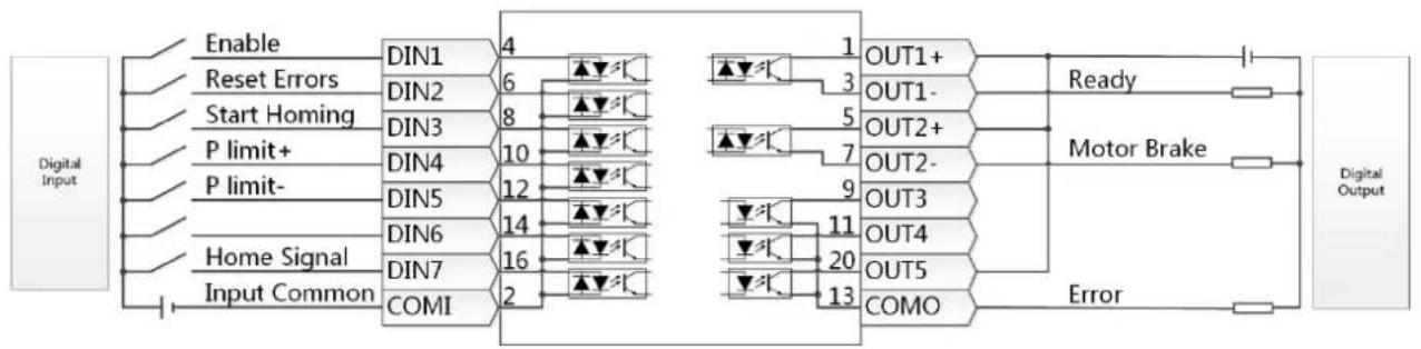
Figure 3-4 shows NPN wiring for the digital input and outputs. Figure 3-5 shows the PNP wiring.
flowchart
graph LR
    A["Digital Input"] --> B["Enable"]
    A --> C["Reset Errors"]
    A --> D["Start Homing"]
    A --> E["P limit+"]
    A --> F["P limit-"]
    A --> G["Home Signal"]
    A --> H["Input Common"]

    B --> I["DIN1 4"]
    C --> J["DIN2 6"]
    D --> K["DIN3 8"]
    E --> L["DIN4 10"]
    F --> M["DIN5 12"]
    G --> N["DIN6 14"]
    H --> O["DIN7 16"]
    I --> P["COMI 2"]

    Q["Motor Brake"] --> R["OUT1+"]
    Q --> S["OUT1-"]
    Q --> T["OUT2+"]
    Q --> U["OUT2-"]
    Q --> V["OUT3"]
    Q --> W["OUT4"]
    Q --> X["OUT5"]
    Q --> Y["COMO"]

    R --> Z["Ready"]
    S --> AA["Error"]

    style A fill:#f9f,stroke:#333
    style Q fill:#ccf,stroke:#333
Figure 3-5: X4 PNP-wiring of digital inputs and digital outputs
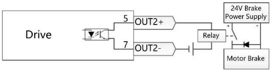
CMMB series motor controllers do not support the direct motor brake control output. We suggest to using the OUT1 or OUT2 pin to control a relay which is connected to the motor brake. The wiring schematic is as follows:
flowchart
graph LR
    Drive -->|5 OUT2+| Relay
    Drive -->|7 OUT2-| Relay
    Relay -->|24V Brake Power Supply| MotorBrake
    MotorBrake -->|+ -| Relay
Figure 3-6: Motor brake wiring
3.2.5 Encoder input (X5)
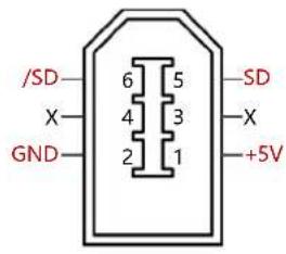
Table 3-5: Encoder input
 | Pin number Definition Function | ||
| 1 +5V 5VDC power supply for encoder | |||
| 2 GND Signal ground (+5 V) | |||
| 5 SD Serial data signal | |||
| 6 /SD Serial data signal | |||
| Other | NC | Reserved | |
3.3 Wiring of the CMMB servo system
flowchart
graph TD
    A["220VAC Power Supply"] -->|N| B["Circuit Breaker (MCCB)"]
    A -->|L| C["Noise Filter (NF)"]
    B --> D["Fuse 1"]
    C --> E["Fuse 2"]
    D --> F["Magnetic Contactor (MC)"]
    E --> G["Magnetic Contactor (MC)"]
    F --> H["Braking Resistor"]
    G --> H
    H --> I["L1C L2C L1 L2 RB1 RB- U V W PE"]
    I --> J["FESTO"]
    J --> K["RS232 Cable"]
    K --> L["Motor Power Cable"]
    L --> M["Brake 24V Power Supply"]
    M --> N["Motor Brake Cable"]
    N --> O["Motor Encoder Cable"]
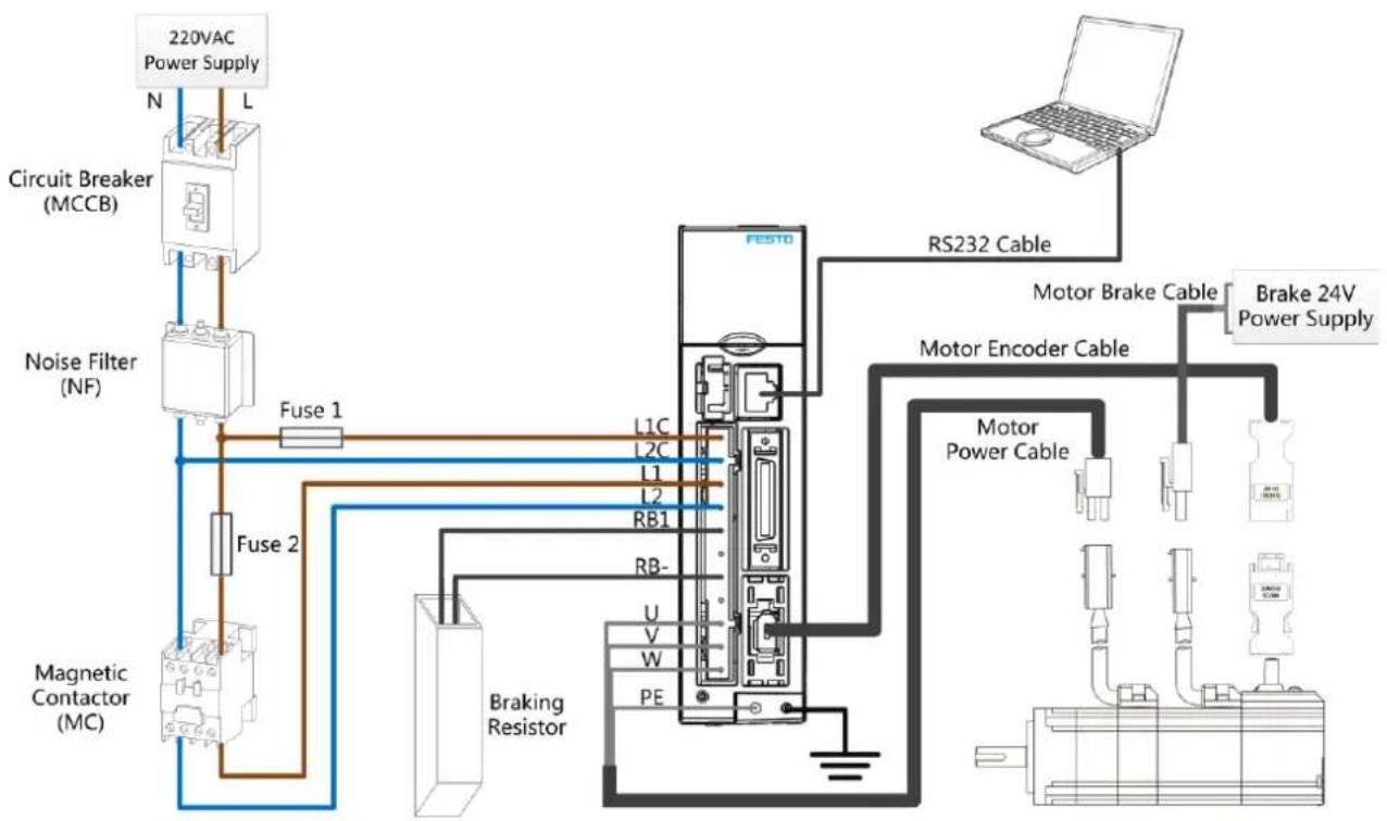
Figure 3-7: Wiring of the CMMB servo system

Warning
Danger of electric shock
Before conducting any installation or maintenance work on the CMMB controller, switch supply power off. After switching off the power, wait for at least 10 minutes before touching any contacts and make sure that the charge lamp on the controller's front panel is off.
Never open the device during operation. Keep all covers and control cabinet doors closed during operation.
Never remove safety devices and never reach into live parts and components.
Connect the PE conductor correctly before switching on the controller.

Warning
Danger of electric shock
The CMMB motor controller uses mains voltage for logic supply power. Even when supply power to the controller is switched off and the DC bus is discharged (charge lamp at front is off), the control power input X2: L1C/L2C may still have active mains voltage.
If the LED at the front of the motor controller is on, mains voltage must be expected at X2: L1C/L2C.

Note
Use NEBM cables (see 2.1.3) to connect the CMMB motor controller to the EMMB servo motor, and connect the PE wire of the NEBM motor cable to the left PE screw at the front of the motor controller.
Do not subject the NEBM cables or the wires at the X2 connector to mechanical stressing. Comply with international and local standards and laws for the wiring and installation of live components in the electric cabinet such as fuses, circuit breakers and contactors in relation with the mains power supply of the motor controller.
In order to comply with EMC directive and standards, use suitable RF filters for installation of the motor controller mains supply.
3.3.1 Selection of fuses, braking resistors and circuit breakers
Fuses, braking resistors and circuit breakers should be selected according to following specifications:
Table 3-6: Recommended fuse
| Model | Control power supply fuse (Fuse1) specification | Drive power supply fuse (Fuse2) specification |
| CMMB-AS-01 | 1.0A/250VAC | 3.5A/250VAC |
| CMMB-AS-02 | 1.0A/250VAC | 3.5A/250VAC |
| CMMB-AS-04 | 1.0A/250VAC | 7A/250VAC |
| CMMB-AS-07 | 1.0A/250VAC | 15A/250VAC |
Table 3-7: Recommended braking resistor
| Model | Resistance [Ω] | Power [W] | Withstanding voltage [VDC] |
| CMMB-AS-01 | 75 100 500 | ||
| CMMB-AS-02 | |||
| CMMB-AS-04 | |||
| CMMB-AS-07 |
Table 3-8: Recommended circuit breaker
| Model | Rated current[A] | Poles [P] | Voltage[VAC] | Release type |
| CMMB-AS-01 | 10 2 | 230 C | ||
| CMMB-AS-02 | ||||
| CMMB-AS-04 | 16 2 | |||
| CMMB-AS-07 |
Chapter 4 Controller setup with LED panel
After the servo system has been wired properly and in accordance with relevant standards, the motor controller can be setup for the desired application.
The CMMB motor controller provides an LED panel at the front panel. It consists of a 5-digit LED display and four buttons. Following general functions are possible with this LED panel:
- Real time display of actual values at the LED display. The value which is displayed can be selected in the F001 menu, Real_Speed_RPM (d1.25) is shown as a default display, for other selections please see chapter 9 table 9-1.
- Blinking display of error or warning information
- Display of controller parameters and their modification
- Easy controller setup using special menu functions EASY and tunE
Different functions and parameter groups are arranged in a menu structure. The 4 buttons can be used to navigate through that menu structure, select single parameters, modify values and access special functions.
4.1 Panel operation
Table 4-1: Panel view
| Item Function | |
| Dot 1 | N/A |
| Dot 2 | N/A |
| Dot 3 | When setting parameters: distinguishes between the data for the current object group and the object address inside the group.When the internal 32 bit data_appears at the display, the display is showing the high 16 bit of the current 32 bit data.Indicates that the earliest error information in the error history is being displayed when the error history record in F007 appears at the display. |
| Dot4 | When setting parameters and displaying real-time data, indicates the format of the data: HEX data when dot 4 is on and DEC data when dot 4 is off.Indicates that the latest error information in the error history is being displayed when the error history record in F007 appears at the display. |
| Dot5 | Lights up to indicate that data has been successfully modified when setting parameters.Lights up to indicate that internal data is being displayed when real time data appears.The controller's power stage is operative when dot 5 flickers. |
| MODE | Switch function menu.When setting parameters, press briefly to switch the setting bit, press and hold to return to the last menu. |
| ▲ | Increases the value. |
| ▼ | Reduces the value. |
| SET | Enter menu.Check the values of the parameters.Confirm the setting to access the next step.When the internal 32 bit data appears at the display, press and hold to switch high / low 16 bit. |
| Overall flash | Error or warning status. Lit up for 1s and dark for 1s indicates a controller error. Continuous flashing (3 consecutive rapid flashes) indicates that the controller is in a warning state. |
4.2 Panel menu structure and navigation
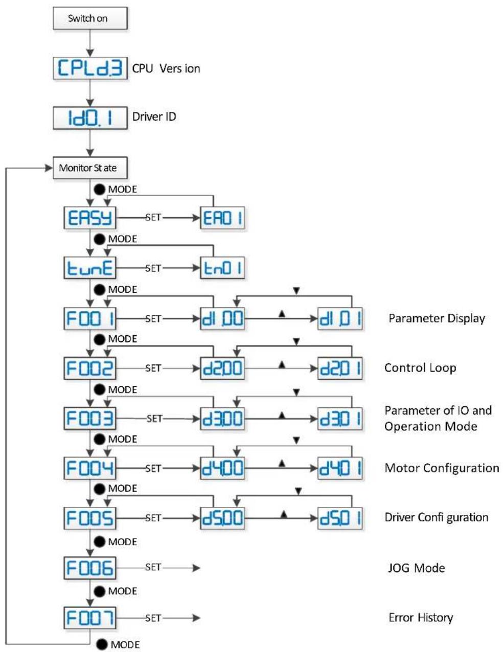
The following flowchart shows the main structure of the panel. The user can select single parameters, modify values and access special functions using this flow. A list of all accessible parameters and values can be found in chapter 9.
flowchart
graph TD
    A["Switch on"] --> B["CPLd3"]
    B --> C["Driver ID"]
    C --> D["Monitor State"]
    D --> E["EASY"]
    E --> F["SET"]
    F --> G["EAD 1"]
    E --> H["tunE"]
    H --> I["SET"]
    I --> J["tn0 1"]
    E --> K["F00 1"]
    K --> L["SET"]
    L --> M["d1.00"]
    M --> N["d1.0 1"]
    K --> O["F002"]
    O --> P["SET"]
    P --> Q["d200"]
    Q --> R["d20 1"]
    K --> S["F003"]
    S --> T["SET"]
    T --> U["d300"]
    U --> V["d30 1"]
    K --> W["F004"]
    W --> X["SET"]
    X --> Y["d400"]
    Y --> Z["d40 1"]
    K --> AA["F005"]
    AA --> AB["SET"]
    AB --> AC["d500"]
    AC --> AD["d50 1"]
    K --> AE["F006"]
    AE --> AF["SET"]
    AF --> AG["JOG Mode"]
    K --> AH["F007"]
    AH --> AI["SET"]
    AI --> AJ["Error History"]
Figure 4-1: Parameters setting
4.3 Easy Use function
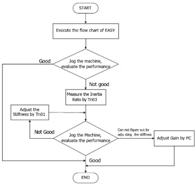
The Easy Use function helps users setup the CMMB motor controller for the main types of applications in a very short time. The LED panel guides the userstep by step through the settings of the few most important parameters in order to prepare the controller for the desired application. The servo control loops of the motor controller are pre-configured to useful default settings which are adequate for many applications at as they are. A robust auto-tuning function can be used additionally to identify the applied mechanical system more precisely. After that, the user only needs to adjust the controller's servo performance with the stiffness parameter.
4.3.1 Setup process with Easy Use function
The process for setting up the CMMB motor controller with the Easy Use function follows a simple procedure. Step 1: The parameters of the EASY panel menu have to be accessed and confirmed, or set one by one. The auto-recognized motor type can be confirmed, the control interface has to be selected, interface-related main parameters have to be set and the mechanical- and control-application types must be chosen. Afterwards, these parameters have to be saved and the controller has to be rebooted. As a result of these settings the controller is configured for a suitable I/O setting and the servo control loop parameters are set to matching defaults. The controller is ready for use for a wide range of standard applications and can be tested.
Step 2: If the servo control performance of the controller has to be further improved, the tunE panel menu must be accessed. With the help of the functions in this menu, the controller can start an auto-tuning motor run in order to identify motor load conditions and to measure the inertia. After that the controller calculates the inertia ratio, which is the ratio of the measured inertia and the motor inertia. Depending on the obtained inertia ratio the controller defines a suitable stiffness value for the servo behavior. Using the inertia ratio and the stiffness value the controller tunes the servo loops automatically.
Step 3: Inside the tunE menu the stiffness can be adjusted up/down simply by panel buttons. The stiffness adjustment can be done also during the testing of the application, while the controller is being commanded via the selected command interface. After finding the best value for stiffness the tunE parameters need to be saved and the controller is finally ready for use. If the adjustment of the stiffness does not result in the required performance, the PC software "CMMB configurator" can be used to for further optimisation.
flowchart
graph TD
    A["START"] --> B["Execute the flow chart of EASY"]
    B --> C{Jog the machine, evaluate the performance}
    C -->|Good| D["Adjust the Stiffness by Tn01"]
    C -->|Not good| E["Measure the Inertia Ratio by Tn03"]
    E --> F{Jog the Machine, evaluate the performance}
    F -->|Good| G["END"]
    F -->|Not Good| H["Adjust Gain by PC"]
    H --> G
    C -->|Not good| I["Measure the Inertia Ratio by Tn03"]
    I --> F
    style C fill:#f9f,stroke:#333
    style F fill:#f9f,stroke:#333
Figure 4-2: Flow chart of the Easy Use function
4.3.2 Flowchart and description of the EASY menu
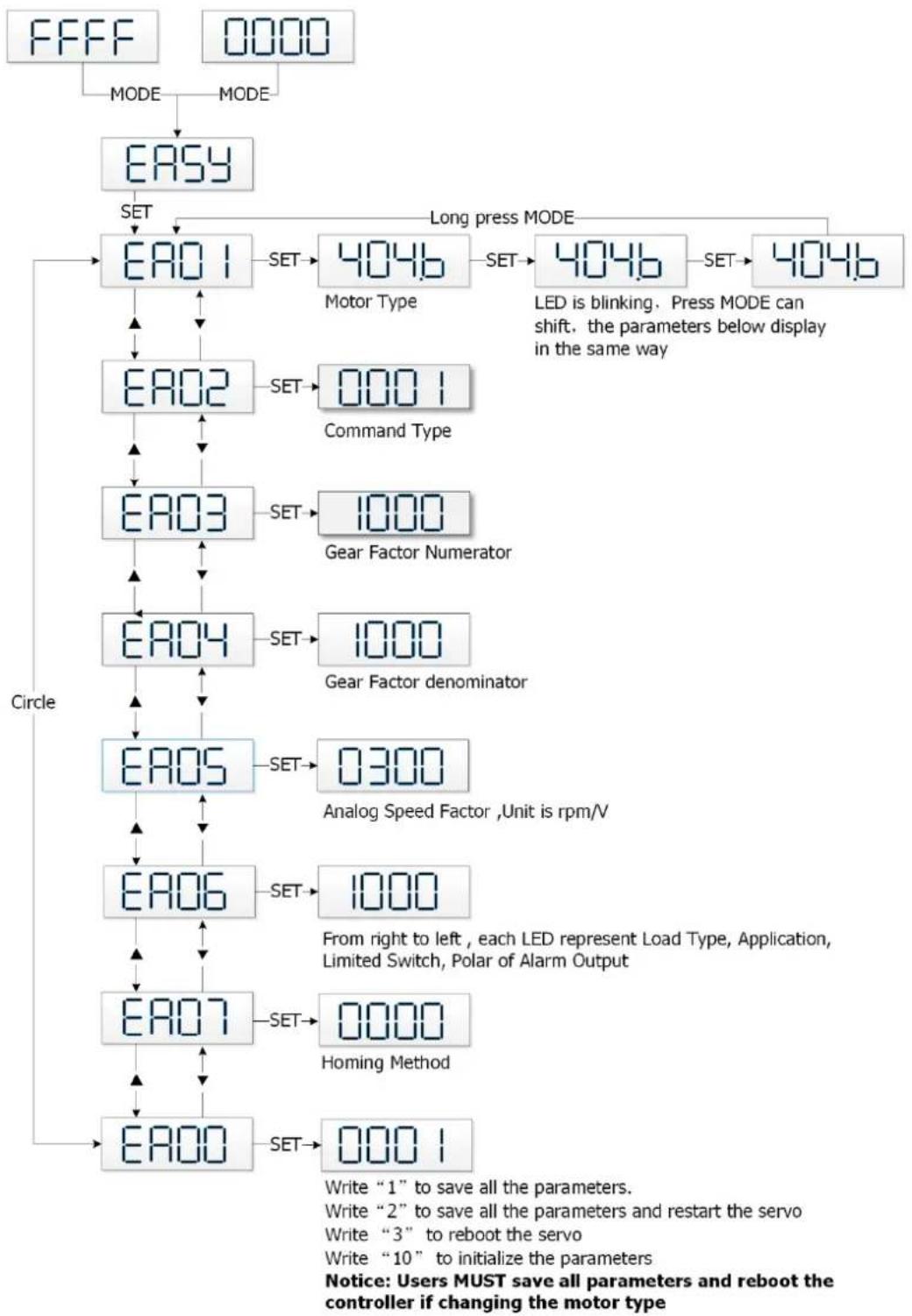
The following flowchart and table explain the procedure for settings in the EASY menu in detail.
flowchart
graph TD
    A["FFFF"] --> B["MODE"]
    C["0000"] --> D["MODE"]
    B --> E["EASY"]
    D --> E
    E --> F["SET"]
    F --> G["EA01"]
    G --> H["SET"]
    H --> I["404b Motor Type"]
    I --> J["SET"]
    J --> K["404b LED is blinking. Press MODE can shift, the parameters below display in the same way"]
    K --> L["SET"]
    L --> M["404b Gear Factor Numerator"]
    M --> N["SET"]
    N --> O["1000 Gear Factor denominator"]
    O --> P["SET"]
    P --> Q["EA04"]
    Q --> R["SET"]
    R --> S["1000 Gear Factor denominator"]
    S --> T["SET"]
    T --> U["EA05"]
    U --> V["SET"]
    V --> W["0300 Analog Speed Factor ,Unit is rpm/V"]
    W --> X["SET"]
    X --> Y["EA06"]
    Y --> Z["SET"]
    Z --> AA["1000 From right to left, each LED represent Load Type, Application, Limited Switch, Polar of Alarm Output"]
    AA --> AB["SET"]
    AB --> AC["EA07"]
    AC --> AD["SET"]
    AD --> AE["0000 Homing Method"]
    AE --> AF["SET"]
    AF --> AG["EA00"]
    AG --> AH["SET"]
    AH --> AI["0001 Write "1" to save all the parameters. Write "2" to save all the parameters and restart the servo Write "3" to reboot the servo Write "10" to initialize the parameters Notice: Users MUST save all parameters and reboot the controller if changing the motor type"]
    style A fill:#f9f,stroke:#333
    style C fill:#f9f,stroke:#333
    style K fill:#f9f,stroke:#333
    style M fill:#f9f,stroke:#333
    style L fill:#f9f,stroke:#333
    style N fill:#f9f,stroke:#333
    style O fill:#f9f,stroke:#333
    style Q fill:#f9f,stroke:#333
    style R fill:#f9f,stroke:#333
    style S fill:#f9f,stroke:#333
    style T fill:#f9f,stroke:#333
    style U fill:#f9f,stroke:#333
    style V fill:#f9f,stroke:#333
    style W fill:#f9f,stroke:#333
    style X fill:#f9f,stroke:#333
    style Y fill:#f9f,stroke:#333
    style Z fill:#f9f,stroke:#333
    style AA fill:#f9f,stroke:#333
    style AB fill:#f9f,stroke:#333
Figure 4-3: Flowchart of the EASY menu

Information
The menu is exited automatically if there is no operation in 30s, and users have to start again. Entered data is valid immediately, but must be saved via EA00.
Table 4-2: EASY menu parameters
| LED | Parameter | Description | Default |
| EA01 Motor Type | For a new motor controller, the set motor type is "00" and "3030" appears at the LED display. If the new motor controller is connected to a valid motor, the motor type is auto-recognized and saved.The motor type saved in the controller and the connected motor type are compared later on. If they are different, "FFFF" flashes at the LED display. The user needs to confirm the EA01 value, save motor data and reboot the controller to eliminate this state.Examples of motor type, motor code and EA01 display value.Motor code Motor type LED displayYY EMMB-AS-40-01... 5959Y0 EMMB-AS-60-02... 3059Y1 EMMB-AS-60-04... 3159Y2 EMMB-AS-80-07... 3259 | / | |
| EA02 Command Type | The command type affects controller-internal interface settings, the initial operation mode after power on and the default settings for DIN- and OUT functions (refer to table 4-3).0: CW/CCW pulse train mode Operation mode = -41: P/D pulse train mode Operation mode = -42: A/B phase control master / slave mode Operation mode = -46: Analog velocity mode by AIN1 Operation mode = -37: Analog velocity mode by AIN2 Operation mode = -38: Communication9: Position table mode Operation mode = 1 | 1 | |
| EA03 | Gear Factor Numerator | Used when EA02 is set to 0-2.By default, the display shows the values in decimal format. If the number is greater than 9999, the display is in hexadecimal format. | 1000 |
| EA04 | Gear Factor Denominator | 1000 | |
| EA05 | Analog Speed Factor | Used when EA02 is set to 6 or 7.The relationship between analog input voltage and motor velocity the unit of measure is rpm/V.For controller use with standard EMMB-AS motors, the maximum value is 374, the maximum velocity is 3740rpm/10v/.For more details see chapter 9.3 (d3.29). | 300 |
| EA06 | 1.Load type2.Application3.Limit switch4. Alarm output polarity | The meaning of each digit of the LED display from right to left.(1) Load type, influences the control loop.0: No load1: Belt drive2: Ball screw(2) Application, influences the control loop.0: P2P1: CNC2: Master / slave mode(3) Limit switch.0: Controller default1: Delete the limit switch function(4) Polarity of OUT50: Normally closed contacts1: Normally open contacts | 1001 with Firmware V00121011 with Firmware V0013 |
| EA07 | Homing method | Refer to chapter 6.6 | 0 |
| EA00 | Save Parameters | Write "1" to save control and motor parameters.Write "2" to save control and motor parameters and reboot the servo.Write "3" to reboot the servo.Write "10" to initialize the control parameters.Notice:Users must save control and motor parameters and reboot the controller after changing the motor type in EA01.After saving the parameters, the servo will set the control loop parameters according to the load type and application. | / |
As a result of setting the command type in EA02, the digital I/O configuration of the controller is defaulted differently, depending on the command type setting as shown in the following table:
Table 4-3: The default settings related to EA02
| Pulse Train | Position table | Analog Input for Velocity Control | Control via RS232 | ||||
| CW/CCW P/D (default) A/B | Channel 1 Channel 2 | ||||||
| EA02 0 | 1 2 9 6 7 8 | ||||||
| DIN1 | Enable | Enable | Enable | Enable | Enable | Enable | |
| DIN2 | Reset Errors | Reset Errors | Reset Errors | Reset Errors | Reset Errors | Reset Errors | |
| DIN3 | Start Homing | Start Homing | Start Homing | Start Homing | Start Homing | Start Homing | |
| DIN4 | P limit+ | P limit+ | P limit+ | PosTable Idx0 | P limit+ | P limit+ | P limit+ |
| DIN5 | P limit- | P limit- | P limit- | PosTable Idx1 | P limit- | P limit- | P limit- |
| DIN6 | Start PosTable | ||||||
| DIN7 | Home Signal | Home Signal | Home Signal | Home Signal | Home Signal | Home Signal | Home Signal |
| OUT1 | Ready | Ready | Ready | Ready | Ready | Ready | Ready |
| OUT2 | Motor Brake | Motor Brake | Motor Brake | Motor Brake | Motor Brake | Motor Brake | Motor Brake |
| OUT3 | Pos Reached | Pos Reached | Pos Reached | Pos Reached | Velocity Reached | Velocity Reached | Pos Reached |
| OUT4 | Zero Speed | Zero Speed | Zero Speed | PosTable Active | Zero Speed | Zero Speed | Zero Speed |
| OUT5 | Error | Error | Error | Error | Error | Error | Error |

Note
Be aware of the different (default) setting of the digital I/O configuration after setting the command type in EA02 or changing a motor type. When settings are changed, an active function may be assigned to digital inputs which have not been in use before as a result of the new defaults, and signals applied to the digital inputs may inadvertently trigger DIN functions. It's recommended to proceed with EASY menu settings with unplugged X4 connector or disconnected power supply to the digital inputs.
It's strongly recommended to process the EASY menu with switched off drive power input.
Double check X4 wiring before switching on drive power input.

Information
The EASY and tunE menus are designed to be set with button originally. For safety reasons, the EASY and tunE menus provide only the parameters EA00, EA01 and tn00 if any of following cases happen, case 1: the user initializes the parameters by any way; case 2: a motor type is connected to the controller which is different to the in EA01 confirmed one; case 3: the motor type setting has been changed by other way rather than through EA01 (e.g. by PC software).
After the motor type becomes confirmed in EA01, the contents of the entries in the menus get default values and the menus get back the full function.
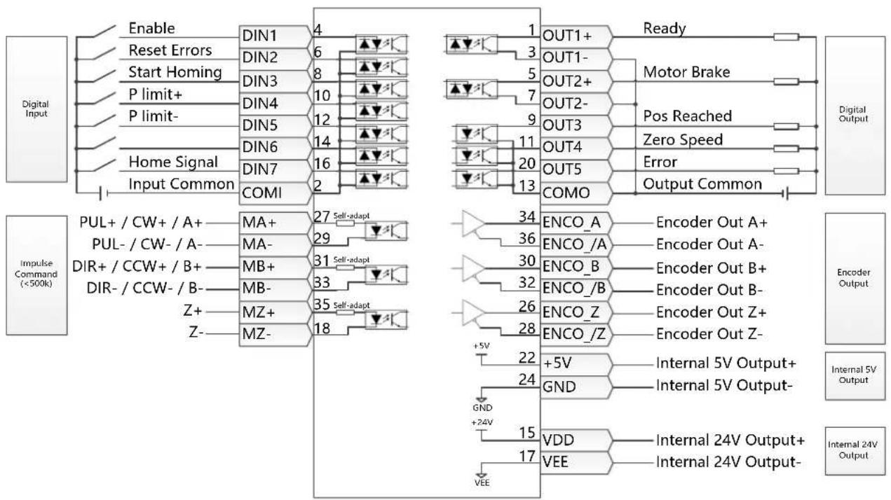
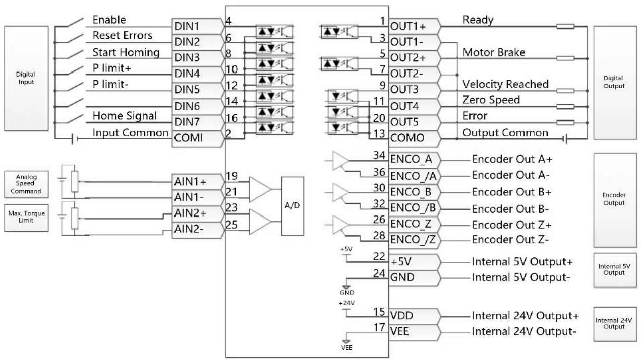
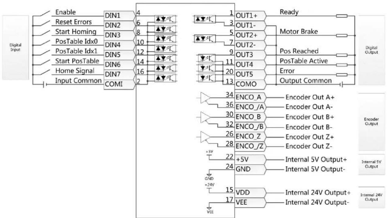
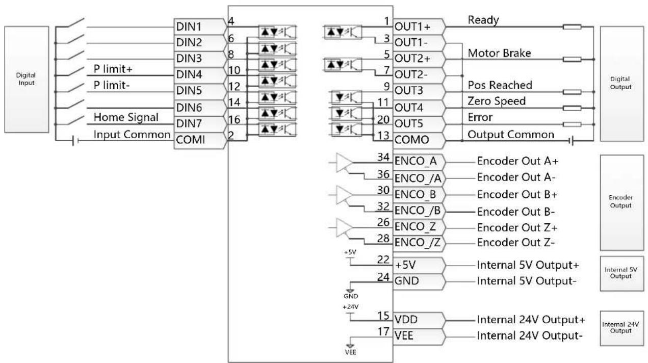
The following pages show four different I/O function configurations based on different command type settings in EA02 and typical related wiring diagrams for I/O connector X4.
Pulse train mode configuration, command types 0, 1 or 2 in EA02:
flowchart
graph TD
    A["Digital Input"] --> B["Enable"]
    B --> C["DIN1 4"]
    C --> D["Reset Errors"]
    D --> E["DIN2 6"]
    E --> F["Start Homing"]
    F --> G["DIN3 8"]
    G --> H["P limit+"]
    H --> I["DIN4 10"]
    I --> J["P limit-"]
    J --> K["DIN5 12"]
    K --> L["Home Signal"]
    L --> M["DIN6 14"]
    M --> N["DIN7 16"]
    N --> O["Input Common"]
    O --> P["COMI 2"]

    Q["Motor Brake"] --> R["OUT1+ 3"]
    R --> S["OUT1- 5"]
    S --> T["OUT2+ 7"]
    T --> U["OUT2- 9"]
    U --> V["OUT3 11"]
    V --> W["OUT4 20"]
    W --> X["OUT5 13"]
    X --> Y["COMO"]
    Y --> Z["Ready"]
    Z --> AA["Output Common"]

    AB["Input Command (<500k)"] --> AC["PUL+ / CW+ / A+ MA+ 27 Self-adapt"]
    AC --> AD["PUL- / CW- / A- MA- 29 Self-adapt"]
    AD --> AE["DIR+ / CCW+ / B+ MB+ 31 Self-adapt"]
    AE --> AF["DIR- / CCW- / B- MB- 33 Self-adapt"]
    AF --> AG["Z+ MZ+ 35 Self-adapt"]
    AG --> AH["Z- MZ- 18 Self-adapt"]

    AI["Encoder Output"] --> AJ["ENCO_A Encoder Out A+ 34"]
    AJ --> AK["ENCO_/A Encoder Out A- 36"]
    AK --> AL["ENCO_B Encoder Out B+ 30"]
    AL --> AM["ENCO_/B Encoder Out B- 32"]
    AM --> AN["ENCO_Z Encoder Out Z+ 26"]
    AN --> AO["ENCO_/Z Encoder Out Z- 28"]
    AO --> AP["+5V +5V +24V GND +24V VDD 15 VEE"]
    AP --> AQ["Internal 5V Output+ GND - Internal 5V Output- VDD 17 VEE"]

    AR["Internal 5V Output"] --> AS["VDD - Internal 24V Output+ GND - Internal 24V Output- VEE"]

    AT["Internal 24V Output"] --> AU["VDD - Internal 24V Output+ GND - Internal 24V Output- VEE"]
Figure 4-4: X4 wiring in pulse train mode
Analog control mode configuration, command types 6 or 7 in EA02:
flowchart
graph TD
    A["Digital Input"] --> B["Enable"]
    B --> C["DIN1 4"]
    C --> D["Reset Errors"]
    D --> E["DIN2 6"]
    E --> F["Start Homing"]
    F --> G["DIN3 8"]
    G --> H["P limit+"]
    H --> I["DIN4 10"]
    I --> J["P limit-"]
    J --> K["DIN5 12"]
    K --> L["Home Signal"]
    L --> M["DIN6 14"]
    M --> N["DIN7 16"]
    N --> O["Input Common COMI 2"]

    P["Analog Speed Command"] --> Q["AIN1+ 19"]
    P --> R["AIN1- 21"]
    P --> S["AIN2+ 23"]
    P --> T["AIN2- 25"]

    U["Max. Torque Limit"] --> V["A/D"]

    W["Digital Output"] --> X["Ready"]
    X --> Y["Motor Brake"]
    Y --> Z["Velocity Reached"]
    Z --> AA["Zero Speed"]
    AA --> AB["Error"]
    AB --> AC["Output Common COMO"]

    AD["Encoder Output"] --> AE["Encoder Out A+"]
    AD --> AF["Encoder Out A-"]
    AD --> AG["Encoder Out B+"]
    AD --> AH["Encoder Out B-"]
    AD --> AI["Encoder Out Z+"]
    AD --> AJ["Encoder Out Z-"]

    AK["Internal 5V Output+"] --> AL["VDD"]
    AK --> AM["VDD"]
    AK --> AN["VDD"]

    AO["Internal 24V Output+"] --> AP["VDD"]
    AO --> AQ["VDD"]
    AO --> AR["VDD"]

    AS["Internal 24V Output-"] --> AT["VDD"]
    AS --> AU["VDD"]

    style A fill:#f9f,stroke:#333
    style P fill:#ccf,stroke:#333
    style AD fill:#cfc,stroke:#333
    style AK fill:#fcc,stroke:#333
Figure 4-5: X4 wiring in analog control mode
Position table mode, command type 9 in EA02:
flowchart
graph TD
    A["Digital Input"] --> B["Enable"]
    A --> C["Reset Errors"]
    A --> D["Start Homing"]
    A --> E["PosTable Idx0"]
    A --> F["PosTable Idx1"]
    A --> G["Start PosTable"]
    A --> H["Home Signal"]
    A --> I["Input Common"]

    B --> J["DIN1 4"]
    C --> K["DIN2 6"]
    D --> L["DIN3 8"]
    E --> M["DIN4 10"]
    F --> N["DIN5 12"]
    G --> O["DIN6 14"]
    H --> P["DIN7 16"]
    I --> Q["COMI 2"]

    J --> R["OUT1+"]
    K --> S["OUT1-"]
    L --> T["OUT2+"]
    M --> U["OUT2-"]
    N --> V["OUT3"]
    O --> W["OUT4"]
    P --> X["OUT5"]
    Q --> Y["COMO"]

    R --> Z["Ready"]
    S --> AA["Motor Brake"]
    T --> AB["Pos Reached"]
    U --> AC["PosTable Active"]
    V --> AD["Error"]
    W --> AE["Output Common"]

    Z --> AF["Encoder Out A+"]
    Z --> AG["Encoder Out A-"]
    Z --> AH["Encoder Out B+"]
    Z --> AI["Encoder Out B-"]
    Z --> AJ["Encoder Out Z+"]
    Z --> AK["Encoder Out Z-"]

    AG --> AL["+5V"]
    AG --> AM["24V"]

    AH --> AN["VDD"]
    AH --> AO["VEE"]

    AI --> AP["Internal 5V Output+"]
    AI --> AQ["Internal 5V Output-"]

    AJ --> AR["Internal 24V Output+"]
    AJ --> AS["Internal 24V Output-"]

    AK --> AT["Internal 5V Output+"]
    AK --> AU["Internal 5V Output-"]

    AL --> AV["Encoder Out A+"]
    AL --> AW["Encoder Out A-"]

    AM --> AX["Encoder Out B+"]
    AM --> AY["Encoder Out B-"]

    AN --> AZ["Encoder Out Z+"]
    AN --> BA["Encoder Out Z-"]

    AO --> BB["Internal 24V Output+"]
    AO --> BC["Internal 24V Output-"]
Figure 4-6: X4 wiring in position table mode
RS232 control mode, command type 8 in EA02:
flowchart
graph TD
    A["Digital Input"] --> B["DIN1 4"]
    A --> C["DIN2 6"]
    A --> D["DIN3 8"]
    A --> E["DIN4 10"]
    A --> F["DIN5 12"]
    A --> G["DIN6 14"]
    A --> H["DIN7 16"]
    A --> I["COMI 2"]

    J["Home Signal"] --> K["COMI"]

    L["Input Common"] --> M["COMI"]

    N["OUT1+"] --> O["Ready"]
    P["OUT1-"] --> Q["Motor Brake"]
    R["OUT2+"] --> S["Pos Reached"]
    T["OUT2-"] --> U["Zero Speed"]
    V["OUT3"] --> W["Error"]
    X["OUT4"] --> Y["Output Common"]

    Z["ENCO_A"] --> AA["Encoder Out A+"]
    AB["ENCO_/A"] --> AC["Encoder Out A-"]
    AD["ENCO_B"] --> AE["Encoder Out B+"]
    AF["ENCO_/B"] --> AG["Encoder Out B-"]
    AH["ENCO_Z"] --> AI["Encoder Out Z+"]
    AJ["ENCO_/Z"] --> AK["Encoder Out Z-"]

    AL["+5V"] --> AM["+5V"]
    AN["GND"] --> AO["Internal 5V Output+"]
    AP["GND +24V"] --> AQ["VDD"]
    AR["VEE"] --> AS["VDD"]

    AT["Internal 24V Output+"] --> AU["Internal 24V Output-"]

    AV["Internal 5V Output"] --> AW["Encoder Output"]
    AX["Internal 24V Output"] --> AY["Internal 5V Output"]
Figure 4-7: X4 wiring in RS232 control mode
4.3.3 Flowchart and description of the tunE menu
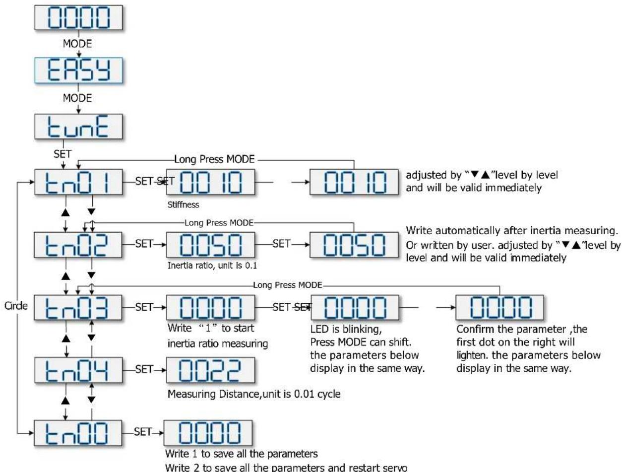
The tunE panel menu includes parameters and functions for auto-tuning with inertia measurement and servo control loop adjustment via just one parameter, namely stiffness.
After processing the EASY menu, the controller defaults the stiffness value and the inertia_ratio based on reasonable estimated values according to, load type and application settings in EA06.
If the inertia ratio is known based on the machine's mechanical system and the payload, the value can be entered directly in tn02 (see table 4-4). The inertia ratio does not need to be 100% correct to achieve reasonable servo performance by adjustment of stiffness alone. But the more accurate the inertia ratio, the better the tuning algorithm can match the different servo control loops to each other. That's why it is highly advisable to obtain a precise inertia ratio result by means of inertia measurement.
The following flowchart and table explain the procedure for settings in the tunE menu in detail.
flowchart
graph TD
    A["0000 MODE"] --> B["EASY MODE"]
    B --> C["tune SET"]
    C --> D["tn01 SET SET 00.10 Stiffness"]
    D --> E["00.10 adjusted by “▼▲”level by level and will be valid immediately"]
    E --> F["tn02 SET 0050 Inertia ratio, unit is 0.1"]
    F --> G["0050 Write automatically after inertia measuring. Or written by user. adjusted by “▼▲”level by level and will be valid immediately"]
    G --> H["tn03 SET 0000 Write “1” to start inertia ratio measuring"]
    H --> I["0000 LED is blinking, Press MODE can shift. the parameters below display in the same way."]
    I --> J["0000 Confirm the parameter ,the first dot on the right will lighten. the parameters below display in the same way."]
    J --> K["tn04 SET 0022 Measuring Distance,unit is 0.01 cycle"]
    K --> L["tn00 SET 0000 Write 1 to save all the parameters"]
    L --> M["Circle"]
    M --> N["tn03 SET 0000"]
    N --> O["Set"]
    O --> P["0000 Convert to save all parameters and restart servo"]
    P --> Q["tn04 SET 0022"]
    Q --> R["Set"]
    R --> S["0022 Convert to save all parameters and restart servo"]
Figure 4-8: Flowchart for the tunE menu
Table 4-4: tunE parameters
| LED | Parameter | Description | Default |
| tn01 Stiffness | Level of control stiffness from 0 to31 determines the bandwidth (BW) of the velocity loop and the position loop (see table 4-5). The larger the value, the greater the stiffness. If this parameter is too large, gain will change excessively and the machine will become unstable.When setting tn01 via the up and down buttons on the panel, entered values are valid immediately, in order to ensure the input of small change steps. | Belt: 10Screw: 13 | |
| tn02 Inertia_Ratio | Ratio of total inertia and motor inertia (unit: 0.1) for example 30 represent an inertia ratio of 3.This value becomes defaulted by the EASY procedure and measured by the inertia measuring function in the tunE menu (tn03).When setting tn02 by the panel up down buttons, the data will be valid immediately, to ensure the input of small change steps. | Belt: 50Screw: 30 | |
| tn03 Tuning_Method | Writing 1 starts auto-tuning inertia measurement. The controller is enabled and the motor executes an oscillating motion for less than 1s.If tuning is successful, Tuning_Method indicates a value of 1. The measured inertia is used to determine the Inertia_Ratio. Stiffness is set to 4 to 12 depending on the inertia ratio. The control loop parameters are set according to Stiffness and Inertia_Ratio.If the inertia measurement fails, Tuning_Method indicates the fail-reason:0: The controller could not be enabled by any reason.-1: Inertia cannot be measured due to too little motion or too little current.-2: The measured inertia result is outside the valid range.-3: The resulting Inertia_Ratio value is greater than 250 (inertia ratio > 25).This is a possible result, but the control loop will not be tuned.-4: The resulting Inertia_Ratio value is larger than 500 (inertia ratio > 50).This is an uncertain result.In the cases 0, -1, -2, -4 Inertia_Ratio is set to 30, in the case -3 Inertia_Ratio is set as measured, Stiffness is set to 7-10In any fail case the control loop parameters are set to Inertia_Ratio of 30 and the set Stiffness values. To make the measured Inertia_Ratio of case -3 become effective, the value of tn02 must be confirmed by SET. | ||
| tn04 Safe_Dist | Inertia measuring distance (unit: 0.01 rev), for example 22 represents 0.22 motor revolutions. The maximum is 0.4 revolutions. | 22 | |
| tn00 | Saving parameters | Write "1" to save control and motor parameters.Write "2" to save control and motor parameters and reboot the servo.Write "3" to reboot the servo.Write "10" to initialize the control parameters.Note: Users must save control and motor parameters and reboot the controller when changing the motor type. |
The auto-tuning algorithm uses the following table of control loop bandwidth settings in relation to the stiffness value:
Table 4-5: Stiffness and control loop settings
| Stiffness | Kpp/[0.01Hz] | Kvp/[0.1Hz] | Output filter [Hz] | Stiffness | Kpp/[0.01Hz] | Kvp/[0.1Hz] | Output filter [Hz] |
| 0 | 70 | 25 | 18 | 16 | 1945 | 700 | 464 |
| 1 | 98 | 35 | 24 | 17 | 2223 | 800 | 568 |
| 2 | 139 | 50 | 35 | 18 | 2500 | 900 | 568 |
| 3 | 195 | 70 | 49 | 19 | 2778 | 1000 | 733 |
| 4 | 264 | 95 | 66 | 20 | 3334 | 1200 | 733 |
| 5 | 334 | 120 | 83 | 21 | 3889 | 1400 | 1032 |
| 6 | 389 | 140 | 100 | 22 | 4723 | 1700 | 1032 |
| 7 | 473 | 170 | 118 | 23 | 5556 | 2000 | 1765 |
| 8 | 556 | 200 | 146 | 24 | 6389 | 2300 | 1765 |
| 9 | 639 | 230 | 164 | 25 | 7500 | 2700 | 1765 |
| 10 | 750 | 270 | 189 | 26 | 8612 | 3100 | 1765 |
| 11 | 889 | 320 | 222 | 27 | 9445 | 3400 | ∞ |
| 12 | 1056 | 380 | 268 | 28 | 10278 | 3700 | ∞ |
| 13 | 1250 | 450 | 340 | 29 | 11112 | 4000 | ∞ |
| 14 | 1500 | 540 | 360 | 30 | 12500 | 4500 | ∞ |
| 15 | 1667 | 600 | 392 | 31 | 13889 | 5000 | ∞ |

Information
When the setting for the stiffness or inertia ratio results in a Kvp value of greater than 4000, it isn't useful to increase stiffness any more

Note
The EASY procedure must be run first and completed, before tunE may be used.
Inertia measurement might cause the machine to oscillate, please be prepared to shut off controller power immediately.
Provide enough mechanical space for motor oscillation during inertia measurement in order to avoid machine damage.

Information
Reasons for the failure of tuning:
-
Incorrect wiring of the CMMB servo system
● DIN function Pre_Enable is configured but not active
● Too much friction or external force is applied to the axis to be tuned
● Too big backlash in the mechanical path between the motor and the load -
Inertia ratio is too large
● The mechanical path contains too soft components (very soft belts or couplings)
For more information about tuning see chapter 7
4.3.4 Jog mode (F006)
The Jog mode is intended to be used for a motor test run by the buttons of the LED panel without the need for any other command signal. No matter other Operation_Mode and velocity settings, in the Jog mode the controller controls the motor rotating with the velocity set by Jog_RPM(d3.52) in instantaneous velocity mode (Operation_Mode=-3, referred to chapter 6.1).
Steps of Jog operation:
Step 1: Check all wiring is right, ESAY flow has been completed.
Step 2: Enter panel address F003->d3.52, set Jog_RPM.
Step 3: Enter panel menu F006, address d6.40 appears, press ▼ several times until d6.15 appears, press ▲ several times until d6.25 appears (this is a safety procedure to ensure the ▲ and ▼ buttons work properly and do not stick in a pressed state).
Step 3: Press SET and the LED display shows 'Jog'.
Step 4: Press and hold ▲ for positive direction or ▼ for negative direction. The controller will become enabled automatically and the motor shaft will rotate with velocity Jog_RPM. Release ▲ and ▼, to stop the motor shaft. If in Step 4 for more than 20 seconds none of ▲ or ▼ was pressed, the Jog operation will quit and a new Jog operation needs to be started from Step 1 again.

Note
In the JOG mode configured Limit Switch functions are not working, the limit switches will be ignored.
Be aware of the human reaction time when controlling the motor in Jog mode. Use slow velocity settings for the Jog mode, especially if the motor travel is limited by mechanical blocks.

Information
If the digital input function Pre_Enable is configured, the Jog mode requires this function active either by the correct DIN signal or by DIN simulation, otherwise the Jog mode will cause a controller error "External enable".
4.3.5 Error History (F007)
The CMMB controller stores the last 8 errors in the error history. Enter panel menu F007, press SET, the value of Error_State(2601.00) (see chapter 5.7, table 5-7) will be shown, if it displays 0001 then it's an extended error, press SET to show the value of Error_State2(2602.00) (see chapter 5.7, table 5-8).
Press ▲ or ▼ to go through all error history. On the LED display, from left to right, dot 3 indicates it's the earliest error, dot 4 indicates it's the latest error. There's mask to specify which errors will be stored in the error history, please see chapter 5.5 for more details.
Table 4-6: Panel F007 example
| F007 LED display | Meaning |
| 000.1 | The latest error is Extended Error. Press “SET” key to see the Error_State 2(2602.00) value. |
| 02.00 | The earliest error is Following Error. |
| 0100 | There was Chop Resistor error, it’s neither the earliest nor the latest error. |
Chapter 5 CMMB configurator, user guide
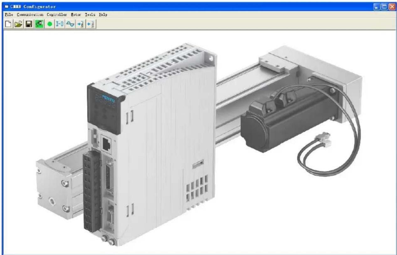
This chapter contains information about how to use the PC software CMMB Configurator.
natural_image
3D rendering of a CMB Configurator with connected motor modules and wiring (no visible text or symbols)Figure 5-1: Main window of CMMB Configurator
5.1 Getting started
5.1.1 Language
Language can be switched between English and Chinese via menu item Tools->Language.
5.1.2 Opening and saving project files
Create a new project file via menu item File->New, or by clicking the button.
Open an existing project via menu item File->Open, or by clicking the button and selecting a .kpjt file.
Save a project via menu item File->Save, or by clicking the button and saving as a .kpjt file.

Information
Only the windows (object list, scope etc.) are saved-parameters in the controller can't be saved in this way.
5.1.3 Starting communication
Click menu item Communication->Communication settings. The following window appears:
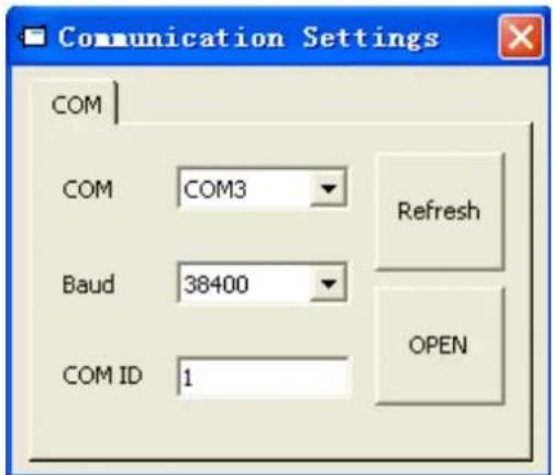
Figure 5-2: Communication settings
Select the right COM port (if it's not shown click the "Refresh" button), baud rate and COM ID (Node ID), and then click the "OPEN" button.
Once communication has been established with the controller, communication can be opened or closed by clicking the button.
5.1.4 Node ID and baud rate
If more than one controller is being used in an application, you may need different node ID for different controllers in order to distinguish amongst them.
The controller's Node ID can be changed via menu item Controller->Controller Property.
Table 5-1: Node ID and baud rate
| Internal address | Type | Name | Value | Unit |
| 100B.00 | Uint8 | Node_ID | DEC | |
| 2FE0.00 | Uint16 | RS232_Baudrate | Baud |

Information
Node ID and baud rate setting are not activated until after saving and rebooting.
5.1.5 Objects (add, delete, help)
Open any window with an object list, move the mouse pointer to the object item and right click. The following selection window appears:
| 5 | 606000 | int8 | Operation_Mode | ||
| 6 | 604000 | uint16 | Controlword | AddDeleteHelp | |
| 7 | 607A00 | int32 | Target_Position | ||
| 8 | 608100 | uint32 | Profile_Speed | ||
| 9 | 608300 | uint32 | Profile_Acc | ||
| 10 | 608400 | uint32 | Profile_Dec | ||
Figure 5-3: Object
Click Add and double click the required object from the Object Dictionary. The selected object is then added to the list.
Click Delete. The selected object is removed from the list.
Click Help to read a description of the selected object in the Object Dictionary.
5.2 Init save reboot
Click Controller->Init Save Reboot. The following window appears:
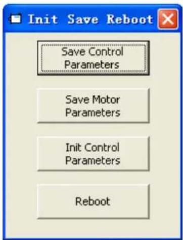
Figure 5-4: Init save reboot
Click the corresponding item to finish the necessary operation.

Information
After completing the init control parameters, the Save Control Parameters and Reboot buttons must be clicked to load the default control parameters to the controller.
5.3 Firmware update
A new motor controller is always delivered with the latest firmware version. If the firmware needs to be updated for any reason, load the new firmware via menu item Controller->Load Firmware.
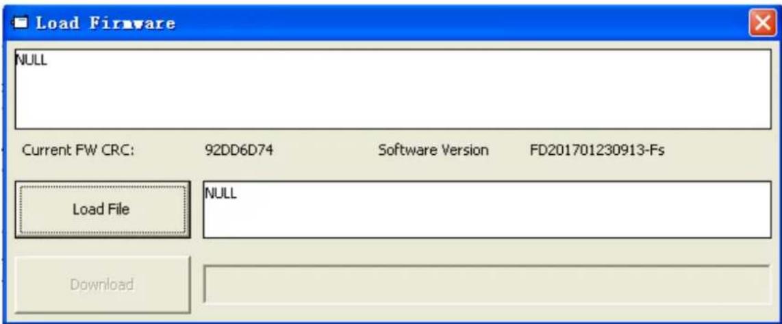
Figure 5-5: Load firmware
Click Load File to select the firmware file (.servo) and then click Download to start loading firmware to the controller.

Information
Do not switch off the power or disconnect the RS232 cable during firmware loading. If the download process is interrupted, first reset controller power. Then select the firmware file and click the Download button, and finally start RS232 communication.
5.4 Read/write controller configuration
This function can be used to read / write multiple parameters simultaneously for large production lots, in order to avoid setting the controller parameters one by one.
5.4.1 Read settings from controller
Click Tools->R/W Controller Configuration->Read Settings from Controller or click the button. The following window appears.
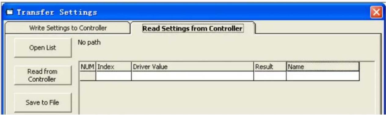
Figure 5-6: Transfer settings
Click Open List to select a parameter list file (.cdo). The parameter appears in the window. Click Read Settings from Controller to get the Drive Value and Result, and then click Save to File to save the settings as a .cdi file.

Information
The .cdo file defines which objects will be read out, but if the object doesn't exist in the controller, the result will be "False"(displayed in red).
5.4.2 Write settings to controller
Click Tools->R/W Controller Configuration->Write Settings to Controller or click the button. The following window appears:

Information
Always disable the controller before writing settings to the CMMB, because some objects cannot be written successfully if the controller is enabled.
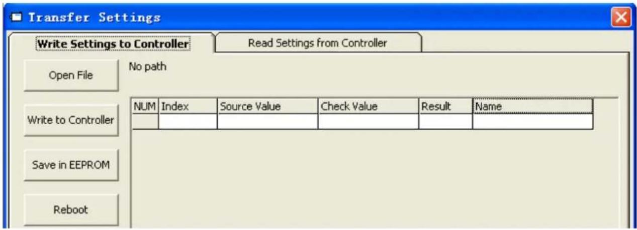
Figure 5-7: Transfer settings
Click Open File to select a parameter settings file (.cdi). The parameter settings appear in the window. The .cdi file contains information including object address, object value and readout result. If readout result is "False", "Invalid" will appear immediately in red ion the Result fied.
Click Write to Controller to get the Check Value and Result. The "False" Result means the value has not been written successfully, probably because the object doesn't exist in the controller. Click Save in EEPROM and Reboot to activate all parameters.
5.5 Digital IO functions
Click menu item Controller->Digital IO Functions or click the I-0 button. The following window appears. Function and polarity are shown as defaults here.
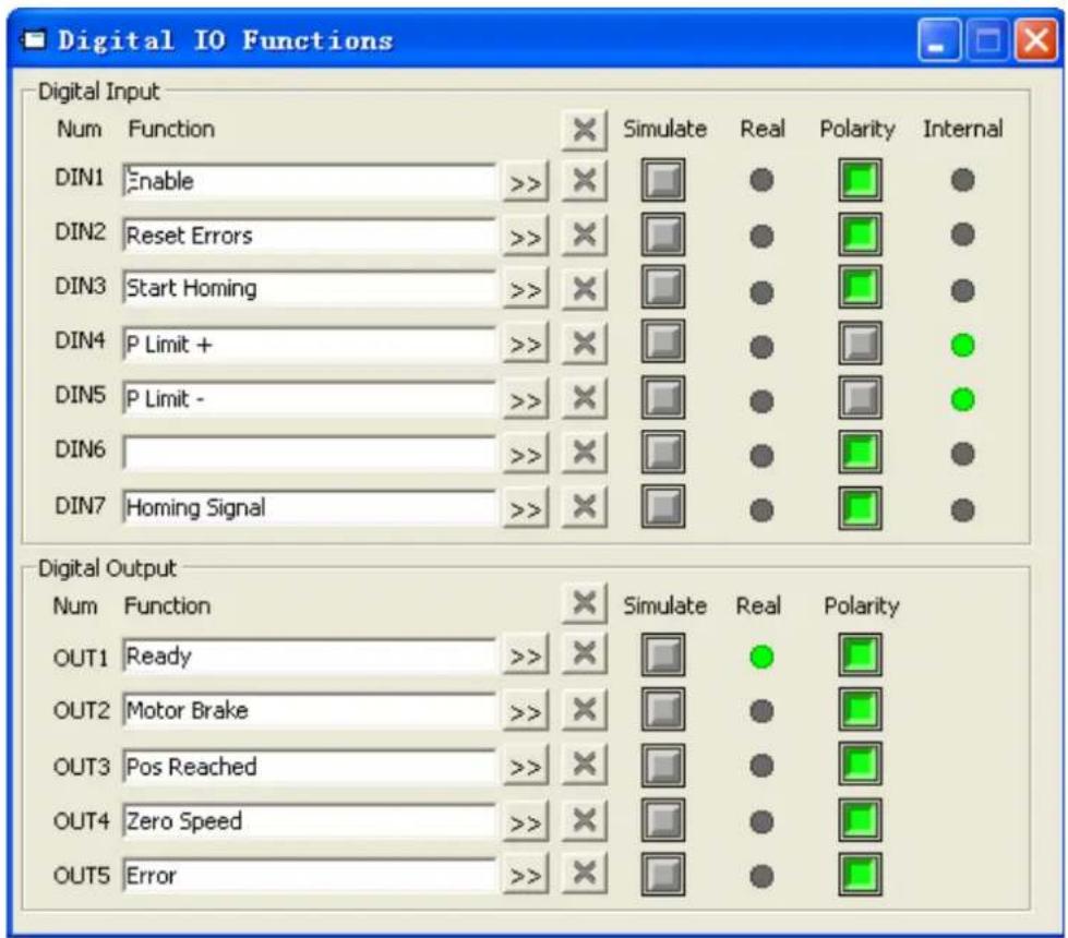
Figure 5-8: Digital IO
5.5.1 Digital inputs
The CMMB motor controller provides 7 digital inputs. The functions of these digital inputs can be configured. Functions can be set via factory defaults or application default settings after processing the Easy setup menu (see chapter 4). The functions of the digital inputs can also be freely configured.

Figure 5-9: Digital Input
Function: Click >> to select DIN function setting, click ✗ to delete the DIN function setting.
Real: Shows the real digital input hardware status.
1 means "active", logic status of the digital input is 1.
0 means "inactive", logic status of the digital input is 0.
Simulate: Simulates the digital input active hardware signal.
1 means the digital input is simulated as "active", logic status 1.
0 means no impact on the digital input logic status.
Polarity: Inverts the logic status of the digital input.
1 means Internal is set to 1 by "active" signal.
0 means Internal is set to 1 by "inactive" signal.
Internal: This is the result of Simulate, Real and Polarity via the logic formula: Internal=(Real OR Simulate) XOR (NOT Polarity)
1 means "active", logic status of the selected function is 1.
0 means "inactive", logic status of the selected function is 0.

Information
- More than one digital input function can be selected for a given digital input. If not contradictory in any way, the selected digital input functions are handled simultaneously.
- Several digital input functions modify controller-internal control variables. Please familiarise yourself with the information in chapter 6.1, especially regarding Controlword and Operation_Mode, before modifying the configuration of any related digital input function.
The following table lists the digital input functions:
Table 5-2: Digital input functions
| DIN Function Description | |
| Enable | Controller enabling1: Enable controller (Controlword= Din_Controlword(2020.0F) , default value=0x2F)0: Disable controller (Controlword = 0x06) |
| Reset Errors | Sets the Controlword to reset errors, active edge: 0 -> 1 |
| Operation Mode sel | Operation_Mode selection1: Operation_Mode=EL.Din_Mode1 (2020.0E), default value = -30: Operation_Mode=EL.Din_Mode0 (2020.0D), default value = -4 |
| Kvi Off | 1: Velocity control loop integrating gain off0: Velocity control loop integrating gain has been setRefer to chapter 7 for more information about Kvi. |
| P limit+ | Positive / negative position limit switch input for “normally closed” limit switches0: position limit is active, the related direction is blocked |
| P limit- | |
| Home Signal | Home switch signal, for homing |
| Invert Direction | Inverts command direction in the velocity and torque mode |
| Din Vel Index0 | Din_Speed Index in the DIN speed mode |
| Din Vel Index1 | |
| Din Vel Index2 | |
| Quick Stop | Sets the controlword to start quick stop. After quick stop, the controlword needs to be set to 0x06 before 0x0F for enabling (if the enable function is configured in Din, just re-enable it) |
| Start Homing | Starts homing. Only makes sense if the controller is enabled. The controller returns to the previous operation mode after homing. |
| Activate Command | Activates the position command. Controls bit 4 of the Controlword, e.g. Controlword=0x2F->0x3F |
| Multifunction0 | Gear ratio switch (refer to chapter 5.5.3 for more details) |
| Multifunction1 | |
| Multifunction2 | |
| Gain Switch 0 | PI control gain switch (refer to chapter 5.5.4 for more details) |
| Gain Switch 1 | |
| Motor Error | 1: Provokes the “Motor temperature” controller error. Can be used to monitor motor temperature by means of an external temperature switch or PTC sensor. Polarity must be set according to sensor type. |
| Fast_Capture1 | Fast Capture (refer to chapter 5.5.5 for more details) |
| Fast_Capture2 | |
| Pre Enable | For safety reasons, Pre_Enable can serve as a signal for indicating whether or not the entire system is ready.1: controller can be enabled0: controller can not be enabled |
| PosTable Cond0 | Position table condition for position table mode |
| PosTable Cond1 | |
| Start PosTable | Start position flow of position table mode |
| PosTable Idx0 | Position table starting index of position table mode |
| PosTable Idx1 | |
| PosTable Idx2 |
Abort PosTable
Abort position flow of position table mode
5.5.2 Digital outputs
The CMMB motor controller provides 5 digital outputs. The functions of these digital outputs can be configured. Functions can be set via factory defaults or application default settings after processing the Easy setup menu (see chapter 4). The functions of the digital outputs can also be freely configured also.

Figure 5-10: Digital output
Function: Click >> to select the OUT function setting. Click ✗ to delete the OUT function setting.
Simulate: Simulates the digital output function logic status 1.

Polarity: Inverts the logic status of the digital output function.

Real: Shows the real digital output status. This is the result of Simulate, Polarity and the logic status of the selected digital output function via the logic formula:
Real=(Dout_Function_Status OR Simulate) XOR (NOT Polarity)
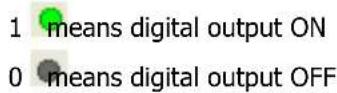

Information
More than one digital output function can be selected for a given digital output. The resulting status is the OR logic of the selected digital output functions.
The following table lists the digital output functions:
Table 5-3: Digital output functions
| OUT Function | Description |
| Ready | Controller is ready to be enabled |
| Error | Controller error |
| Pos Reached | Under position mode, position difference between Pos_Actual and Pos_Target=Position_Window_time(6068.00) |
| Zero Speed | |Speed_1ms(60F9.1A)|<=Zero_Speed_Window(2010.18) and duration >=Zero_Speed_Time(60F9.14) |
| Motor Brake | Signal for controlling the motor brake. By this signal an external relay can be controlled, by which the motor brake is controlled. (see chapter 3.2.4). |
| Speed Reached | |Speed_Error(60F9.1C)|<Target_Speed_Window(60F9.0A) |
| Enc Index | Encoder position is inside a range around the index position. This range is defined by Index_Window(2030.00). |
| Speed Limit | In torque mode actual speed reached Max_Speed(607F.00) |
| Driver Enabled | Controller enabled |
| Position Limit | Position limit function is active |
| Home Found | Home found |
| Enc Warning | Encoder warning |
| PosTable Active | Position table mode running |
5.5.3 Gear ratio switch (expert only)

Information
This function is recommended for experienced users only.
There are 8 groups of gear ratio parameters which can be selected via the digital inputs. Gear ratio is only used for pulse train mode (see chapter 6.5).
Table 5-4: Gear ratio switch
| Internal address | Type | Name | Value | Unit |
| 2508.01 | Int16 | Gear_Factor[0] | Dec | |
| 2508.02 | Uint16 | Gear_Divider[0] | Dec | |
| 2509.01 | Int16 | Gear_Factor[1] | Dec | |
| 2509.02 | Uint16 | Gear_Divider[1] | Dec | |
| 2509.03 | Int16 | Gear_Factor[2] | Dec | |
| 2509.04 | Uint16 | Gear_Divider[2] | Dec | |
| 2509.05 | Int16 | Gear_Factor[3] | Dec | |
| 2509.06 | Uint16 | Gear_Divider[3] | Dec | |
| 2509.07 | Int16 | Gear_Factor[4] | Dec | |
| 2509.08 | Uint16 | Gear_Divider[4] | Dec | |
| 2509.09 | Int16 | Gear_Factor[5] | Dec | |
| 2509.0A | Uint16 | Gear_Divider[5] | Dec | |
| 2509.0B | Int16 | Gear_Factor[6] | Dec | |
| 2509.0C | Uint16 | Gear_Divider[6] | Dec | |
| 2509.0D | Int16 | Gear_Factor[7] | Dec | |
| 2509.0E | Uint16 | Gear_Divider[7] | Dec |
The actual gear ratio is Gear_Factor[x], Gear_Divider[x], whereas x is the BCD code of
bit 0: Multifunction0
bit 1: Multifunction1
bit 2: Multifunction2
A bit which is not configured to a DIN is 0.
Example:

Figure 5-11 Din gear ratio switch example
Multifunction0=0, Multifunction1=1, Multifunction2=1, so x=6, actual gear ratio is Gear_Factor[6], Gear_Divider[6].
5.5.4 Gain switch (expert only)

Information
This function is recommended for experienced users only, who are familiar with the basics of servo loop tuning.
There are 4 groups of PI gain settings, where each group contains the proportional (Kvp) and integral (Kvi) gain of the velocity control loop and the proportional gain (Kpp) of the position control loop. The CMMB motor controller provides several methods for selecting a group of PI gain settings dynamically.
Table 5-5: PI gain setting group parameters
| Internal address | Type | Name | Value | Unit |
| 60F9.01 | Uint16 | Kvp[0] | Dec, Hz | |
| 60F9.02 | Uint16 | Kvi[0] | Dec | |
| 60FB.01 | Int16 | Kpp[0] | Dec. Hz | |
| 2340.04 | Uint16 | Kvp[1] | Dec, Hz | |
| 2340.05 | Uint16 | Kvi[1] | Dec | |
| 2340.06 | Int16 | Kpp[1] | Dec. Hz | |
| 2340.07 | Uint16 | Kvp[2] | Dec, Hz | |
| 2340.08 | Uint16 | Kvi[2] | Dec | |
| 2340.09 | Int16 | Kpp[2] | Dec. Hz | |
| 2340.0A | Uint16 | Kvp[3] | Dec, Hz | |
| 2340.0B | Uint16 | Kvi[3] | Dec | |
| 2340.0C | Int16 | Kpp[3] | Dec. Hz | |
| 60F9.28 | Uint8 | PI_Pointer | Dec | |
| 60F9.09 | Uint8 | PI_Switch | Dec |
The actual PI settings are Kvp[x], Kvi[x], Kpp[x], x=PI_Pointer.
There are 3 methods for changing PI_Pointer.
Method 1: The Gain Switch 0 and / or Gain Switch 1 function is configured to DIN. PI_Pointer is the BCD code of
bit 0: Gain Switch 0
bit 1: Gain Switch 1
If only one bit is configured, the other bit is 0.
Example:

Figure 5-12: Din gain switch example
Gain Switch0=1, Gain Switch1=0, then PI_Pointer=1, the valid PI gain settings are Kvp[1], Kvi[1] and Kpp[1]
Method 2: If Method 1 is not applied, set PI_Switch(6069.09) to 1. Then, while the motor is rotating, set PI_Pointer ti =0. As soon as Pos Reached or Zero Speed, set PI_Pointer to =1
This is the function for a system which needs different PI gain settings for rotation and standstill.

Information
Refer to the OUT function table in chapter 5.5.2 for Pos Reached and Zero Speed definition.
Method 3: If neither method 1 nor method 2 is applied, the PI_Pointer value can be defined by the user. The default setting of 0 is highly recommended.
5.5.5 Fast Capture
The Fast Capture function is used to capture the Position_Actual(6063.00) when the related DIN edge occurs. Response time is maximum 2ms.
Table 5-6: Fast capture objects
| Internal address | Type | Name | Value | Unit |
| 2010.20 | Uint8 | Rising_Captured1 | Dec | |
| 2010.21 | Uint8 | Falling_Captured1 | Dec | |
| 2010.22 | Uint8 | Rising_Captured2 | Dec | |
| 2010.23 | Uint8 | Falling_Captured2 | Dec | |
| 2010.24 | Int32 | Rising_Capture_Position1 | Dec | |
| 2010.25 | Int32 | Falling_Capture_Position1 | Dec | |
| 2010.26 | Int32 | Rising_Capture_Position2 | Dec | |
| 2010.27 | Int32 | Falling_Capture_Position2 | Dec |
When DIN function Fast_Capture1 is configured to DIN and a rising DIN edge occurs, Rising_Captured1 is changed to 1. At the same moment Pos_Actual is stored to Rising_Capture_Position1. If a falling DIN edge occurs, Falling_Captured1 is to 1. At the same moment Pos_Actual is stored to Falling_Capture_Position1. Once Rising_Captured1 or Falling_Captured1 is changed to 1, the user needs to reset them to 0 for the next capturing operation, because any further edges after the first one will not be captured.
See Fast_Capture1 concerning DIN function Fast_Capture2.
5.6 Scope
The scope function is for sampling the selected objects' value with a flexible sample cycle (defined by
Sample Time) and a flexible total sample number (defined by Samples)
During operation, if performance does not meet the requirement or any other unexpected behaviour occurs, it's highly advisable to use the scope function to do the analysis.
Click Controller-->Scope or click to open the scope window
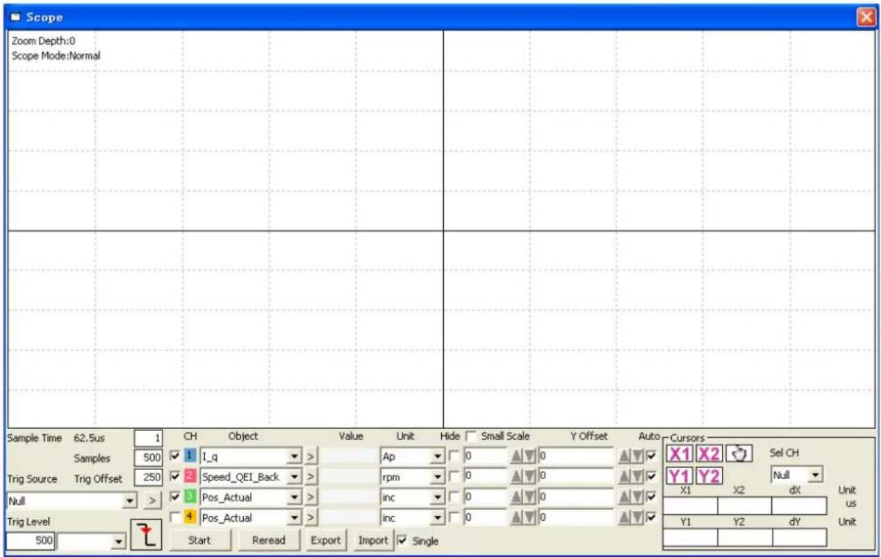
Figure 5-13: Scope window
Trig offset: Number of samples before the trigger event occurs.
Object: Maximum 64-bit length data can be taken in one sample, e.g.: 2 Int32 objects bit or 4 Int16 objects.
Single: ☑ Single means sample for one trigger event only. □ Single means sample continuously.
Zoom in / zoom out the oscillogram: Press the right mouse key and drag to lower right / upper left. Left mouse click on ☐ activates the horizontally drag mode, the icon changes to ☐ and inside the oscillogram display area the mouse cursor changes to finger shape. A zoomed oscillogram can be moved then in horizontal direction by pressing the left mouse button and dragging to left/right.
Left mouse click on 📋 or any zoom-in or zoom-out action cancels the drag mode automatically.
X1 X2
Cursors: Up to 4 scope cursors can be selected by clicking the respective button: Y1 Y2. The scope cursors appear in the oscillogram. Select a channel in the Sel CH list box. Move the mouse pointer to the scope cursor. Press left mouse button and drag the scope cursor to move it. A sample value and the differences of X1, X2 and Y1, Y2 appear in the following fields:
Figure 5-14: Cusor data
Export: Exports the sampled data as a .scope file.
Import: Imports a .scope file and shows the oscillogram in the scope window.
Reread: Rereads the last scope data out of the controller and shows the oscillogram in the scope window.
Auto: If the checkbox Auto is checked, the oscillogram is auto-scaled.
If Auto is not checked, the oscillogram is scaled by scale and offset value in following field:

Figure 5-15: Scale and offsetr data
Scale and offset value can be increased by pressing the ▲ button, and can be reduced by pressing the ▼ button. If Small scale checkbox is checked, scale value changing step is changed to 10% as before.
Scope Mode: On the upper left side of the oscillogram the Scope Mode "Normal" or "Import" is shown.
-Normal: all buttons are active.
Figure 5-16: Scope mode: Normal
-Import: If the oscillogram is an import from a .scope file, the scope mode will be "Import", in this mode the Start, Reread button will be inactive. The "Import" mode can be quit by clicking the "Here" on the hint.
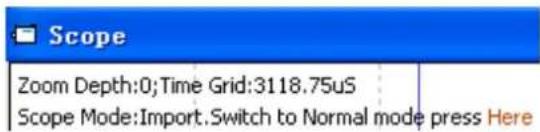
Figure 5-17: Scope mode: Import
5.7 Error display and error history
Error: Click Controller->Error Display or click the button (which turns red if an error occurs). The Error Display window appears. It shows the last errors.
Table 5-7: Error_State(2601.00) Information
| Bit | Error name | Error code | Description |
| 0 | Extended Error | Refer to object "Error_State 2"(2602.00) | |
| 1 | Encoder not connected | 0x7331 | No communication encoder connected |
| 2 | Encoder internal | 0x7320 | Internal encoder error |
| 3 | Encoder CRC | 0x7330 | Communication with encoder disturbed |
| 4 | Controller Temperature | 0x4210 | Heatsink temperature too high |
| 5 | Overvoltage | 0x3210 | DC bus overvoltage |
| 6 | Undervoltage | 0x3220 | DC bus undervoltage |
| 7 | Overcurrent | 0x2320 | Power stage or motor short circuit |
| 8 | Chop Resistor | 0x7110 | Overload, brake chopper resistor |
| 9 | Following Error | 0x8611 | Max. following error exceeded |
| 10 | Low Logic Voltage | 0x5112 | Logic supply voltage too low |
| 11 | Motor or controller IIt | 0x2350 | Motor or power stage IIt error |
| 12 | Overfrequency | 0x8A80 | Pulse input frequency too high |
| 13 | Motor Temperature | 0x4310 | Motor temperature sensor alarm |
| 14 | Encoder information | 0x7331 | No encoder connected or no encoder communication reply |
| 15 | EEPROM data | 0x6310 | EEPROM checksum fault |
Table 5-8: Error_State2(2602.00) Information
| Bit | Error name | Error code | Description |
| 0 | Current sensor | 0x5210 | Current sensor signal offset or ripple too large |
| 1 | Watchdog | 0x6010 | Software watchdog exception |
| 2 | Wrong interrupt | 0x6011 | Invalid interrupt exception |
| 3 | MCU ID | 0x7400 | Wrong MCU type detected |
| 4 | Motor configuration | 0x6320 | No motor data in EEPROM / motor never configured |
| 5 | Reserved | ||
| 6 | Reserved | ||
| 7 | Reserved | ||
| 8 External enable 0x5443 | DIN "pre_enable" function is configured, but the DIN is inactive when the controller is enabled / going to be enabled | ||
| 9 Positive limit 0x5442 | Positive position limit (after homing) - position limit only causes error when Limit_Function (2010.19) is set to 0. | ||
| 10 Negative limit 0x5441 | Negative position limit (after homing) position limit only causes error when Limit_Function(2010.19) is set to 0. | ||
| 11 | SPI internal | 0x6012 | Internal firmware error in SPI handling |
| 12 | Reserved | ||
| 13 | Closed loop direction | 0x8A81 | Different direction between motor and position encoder in closed loop operation by a second encoder. |
| 14 | Reserved | ||
| 15 | Master counting | 0x7306 | Master encoder counting error |

Information
There's a mask checkbox beside every error item, all are defaulted to be checked, means it can be unchecked, means it can't be unchecked. An unchecked item mean the related error will be ignored. The error mask can be set in Error_Mask(2605.01) and Error_Mask(2605.04) also (see table 5-9)
Error History: Click menu item Controller->Error History. The error history list window appears. It shows the last 8 errors' Error codes and respective the related DCBUS voltage, speed, current, controller temperature, Operation_Mode, and controller working time at the moment when the error occurred. There are mask parameters to specify which errors will be stored in the error history (see table 5-9). Table 5-9 Error and error history mask
| Internal address | Type | Name | Meaning (Bit meaning please see table5-7 and table 5-8) | Default |
| 2605.01 | Uint16 | Error_Mask | Mask of Error_State(2601.00). Bit = 0 means related error will be ignored. | 0xFFFF |
| 2605.02 | Uint16 | Store_Mask_ON | Error mask for Error_History of Error_State(2601.00) when controller is enabled. Bit = 0 means related error won't be stored in the Error_History | 0xFBF |
| 2605.03 | Uint16 | Store_Mask_OFF | Error mask for Error_History of Error_State(2601.00) when controller is not enebled. Bit = 0 means related error won't be stored in the Error_History | 0x0000 |
| 2605.04 | Uint16 | Error_Mask2 | Mask of Error_State2(2602.00). bit = 0 means related error will be ignored | 0xFFFF |
| 2605.05 | Uint16 | Store_Mask_ON2 | Error mask for Error_History of Error_State2(2602.00) when controller is enebled. Bit = 0 means related error won't be stored in the Error_History | 0xF1FF |
| 2605.06 | Uint16 | Store_Mask_OFF2 | Error mask for Error_History of Error_State2(2602.00) when controller is not enebled. Bit = 0 means related error won't be stored in the Error_History | 0x003F |
Chapter 6 Operation modes and control modes
Controller parameters can be set via the control panel or the RS232 port (e.g. with CMMB Configurator software). In the following introduction, both the panel address (if it's available) and the internal address will be shown in the object tables.
6.1 General steps for starting a control mode
Step 1: Wiring
Make sure that the necessary wiring for the application is done correctly (refer to chapter 3).
Step 2: IO function configuration
See chapter 5.5 concerning meanings of the IO function and polarity.
Table 6-1: Digital input function
| Panel address | Internal address | Type | Name | Value (hex): description |
| d3.01 | 2010.03 | Uint16 | Din1_Function | 0001: Enable0002: Reset Errors0004: Operation Mode sel0008: Kvi Off0010: P limit+0020: P limit-0040: Homing Signal0080: Invert Direction0100: Din Vel Index00200: Din Vel Index11000: Quick Stop2000: Start Homing4000: Activate Command8001: Din Vel Index28004: Multifunction08008: Multifunction18010: Multifunction28020: Gain Switch 08040: Gain Switch 18100: Motor Error8200: Pre Enable8400: Fast_Capture18800: Fast_Capture29001: PosTable Cond09002: PosTable Cond19004: Start PosTable9008: PosTable Idx09010: PosTable Idx19020: PosTable Idx29040: Abort PosTable |
| d3.02 | 2010.04 | Uint16 | Din2_Function | |
| d3.03 | 2010.05 | Uint16 | Din3_Function | |
| d3.04 | 2010.06 | Uint16 | Din4_Function | |
| d3.05 | 2010.07 | Uint16 | Din5_Function | |
| d3.06 | 2010.08 | Uint16 | Din6_Function | |
| d3.07 | 2010.09 | Uint16 | Din7_Function |
Table 6-2: Digital output function
| Panel address | Internal address | Type | Name | Value (hex): description |
| d3.11 | 2010.0F | Uint16 | Dout1_Function | 0001: Ready0002: Error0004: Pos Reached0008: Zero Speed0010: Motor Brake0020: Speed Reached0040: Enc Index0080: Speed Limit0100: Driver Enabled0200: Position Limit0400: Home Found8002: Enc Warning9001: PosTable Active |
| d3.12 | 2010.10 | Uint16 | Dout2_Function | |
| d3.13 | 2010.11 | Uint16 | Dout3_Function | |
| d3.14 | 2010.12 | Uint16 | Dout4_Function | |
| d3.15 | 2010.13 | Uint16 | Dout5_Function |
Table 6-3: Polarity setting
| Panel address | Internal address | Type | Name | Description |
| d3.53 | 2010.01 | Uint16 | Din_Polarity | Bit 0: DIN1Bit 1: DIN2Bit 2: DIN3...Bit 6: DIN7 |
| d3.54 | 2010.0D | Unit16 | Dout_Polarity | Bit 0: OUT1Bit 1: OUT2Bit 2: OUT3...Bit 5: OUT6 |
Switch\_On\_Auto (expert only)
If the Enable function is not configured to DIN, the controller can be auto-enabled at power-on or reboot, with the following setting:
Table 6-4: Switch_On_Auto
| Panel address | Internal address | Type | Name | Value |
| d3.10 | 2000.00 | Unit8 | Switch_On_Auto | 1 |

Note
This method is not recommended. Please consider all risks and related safety measures before using.
Step 3: Set necessary parameters
The user can access a basic operating parameters list by clicking Controller->Basic Operation. For more parameters, please add according to the introduction in chapter 5.1.5. The following pages in this chapter introduce the operating parameters. Refer to chapter 7 concerning performance adjustment.
Table 6-5: Common parameters
| Panel address | Internal address | Type Name | Description | |
| 6083.00 | Uint32 | Profile_Acc | Profile acceleration, profile deceleration, for Operation_Mode 1 and 3 | |
| 6084.00 | Uint32 | Profile_Dec | ||
| d2.24 | 6080.00 | Uint16 | Max_Speed_RPM | Maximal speed (unit: rpm) |
| d3.16 | 2020.0D | Int8 | Din_Mode0 | If Operation Mode Sel function is configured to DIN,Operation_Mode(6060.00)=Din_Mode0 whenDin_Internal=0; Operation_Mode=Din_Mode1 whenDin_Internal=1 |
| d3.17 | 2020.0E | Int8 | Din_Mode1 | |
| 6073.00 | Uint16 | CMD_q_Max | Output current limit | |
| 6040.00 | Uint16 | Controlword | 0x0F/0x2F: Enable the controller for Operation_Mode 3, -3, -4, 4 and for Position Table mode0x2F->0x3F: Activate absolute position command for Operation_Mode 10x4F->0x5F: Activate relative position command for Operation_Mode 10x0F->0x1F: Start homing for Operation_Mode 60x06->0x86: Reset the controller error0x06: Disable the controller | |
| 6060.00 | Int8 Operation_Mode | -3: Instantaneous velocity mode3: Profile velocity mode1: Position mode-4: Pulse train mode4: Torque mode | ||

Information
Operation_Mode itself is not savable, however, it is set in accordance with the settings in the Command_Type(3041.02) or EA02 in the EASY panel menu to a suitable value (see table 4-2 for EA02). Alternatively, Operation_Mode can be configured to be settable and/or switchable by the DIN function Operate_Mode_Sel (see table 5-2).
Step 4: Save and reboot
See chapter 5.
Step 5: Start operation
Start operation via DIN or PC software.

Information
The DIN function has highest priority – the object value can not be modified manually anymore if it's configured in DIN, e.g. if the enable function is configured, Controlword(6040.00) cannot be modified manually via PC software.
6.2 Velocity mode (-3, 3)
There are 2 kinds of velocity mode: -3 and 3. The velocity command can be specified via Target_Speed or analog input (analog speed mode), or via digital input (DIN speed mode).
Table 6-6: Velocity mode
| Panel address | Internal address | Type | Name | Description | Value |
| 6060.00 | Int8 Operation_Mode | -3: The velocity command is specified directly by Target_Speed. Only the velocity control loop is active.3: The velocity command is specified by Target_Speed with profile acceleration and profile deceleration. Velocity- and position control loops are active. | -3 or 3 | ||
| 60FF.00 | Int32 | Target_Speed | Target velocity | User defined | |
| 6040.00 | Uint16 | Controlword | See table 6-5 | 0x0F, 0x06 |
6.2.1 Analog speed mode
The analog speed object window in the PC software can be accessed via menu item Controller->Control Modes->Analog Speed Mode.
Table 6-7: Analog speed mode
| Panel address | Internal address | Type | Name | Description | Value |
| 2501.06 | Uint16 | ADC1_Buff[1] | AIN1 input real data | Read only | |
| d1.13 | 2502.0F | Int16 | Analog1_out | AIN1 valid input; analog input signal1 (AIN1) input voltage after filter, deadband and offset | |
| 2501.07 | Uint16 | ADC2_Buff[1] | AIN2 input real data | ||
| d1.14 | 2502.10 | Int16 | Analog2_out | AIN2 valid input; analog input signal2 (AIN2), input voltage after filter, deadband and offset | |
| d3.22 | 2502.01 | Uint16 | Analog1_Filter | AIN1 filter (unit: ms) | User defined |
| d3.23 | 2FF0.1D | Int16 | Analog1_Dead_V | AIN1 deadband (unit: 0.01V) | |
| d3.24 | 2FF0.1E | Int16 | Analog1_Offset_V | AIN1 offset (unit: 0.01V) | |
| d3.25 | 2502.04 | Uint16 | Analog2_Filter | AIN2 filter (unit: ms) | |
| d3.26 | 2FF0.1F | Int16 | Analog2_Dead_V | AIN2 deadband (unit: 0.01V) | |
| d3.27 | 2FF0.20 | Int16 | Analog2_Offset_V | AIN2 offset (unit: 0.01V) | |
| 2502.0A | Int16 | Analog_Speed_Factor | AIN speed factor | ||
| d3.28 | 2502.07 | Uint8 | Analog_Speed_Con | 0: analog velocity control OFF, velocity control via Target_Speed(60FF.00)1: Speed control via AIN12: Speed control via AIN2 | 0, 1, 2 |
| 2502.0D | Int16 | Analog_Dead_High | Default is 0, if it's NOT 0, Analog_out>Analog_Dead_High is treated as 0 | User defined | |
| 2502.0E | Int16 | Analog_Dead_Low | Default is 0, if it's NOT 0, Analog_out<Analog_Dead_Low is treated as 0 | ||
| d3.33 | 2FF0.22 | Int16 | Voltage_MaxT_Factor | AIN-MaxTorque factor (unit: mNM/V) | User defined |
| d3.32 | 2502.09 | Uint8 | Analog_MaxT_Con | 0: Analog_MaxTorque control OFF1: Max. torque control via AIN12: Max. torque control by AIN2 | 0, 1, 2 |
For convenience, some new names are used in the formula. Definitions:
AIN1_in: AIN1 input voltage after filter and offset
AIN2_in: AIN2 input voltage after filter and offset
Analog_out: Analog1_out or Analog2_out, depends on wiring and Analog_Speed_Con setting; It's the result of AIN real input, filter, offset and deadband.
Final result:
Analog_Speed control ON:
If Analog_out is not limited by Analog_Dead_High or Analog_Dead_Low:
Target speed[rpm]=Analog_out[V]*Analog_Speed_Factor[rpm/V]; otherwise Target speed[rpm]=0.
Analog_MaxTorque control ON:
Max torque[Nm]=Analog_out[V]*Analog_MaxT_Factor[Nm/V]
Example:
Setting: Analog1_Dead=1V, Analog1_Offset=2V, Analog_Speed_Factor=100rpm/V, Analog_Speed_Con=1, Analog_Dead_High=0V; Analog_Dead_Low=0V;
Where AIN1 input voltage is 5V:
AIN1_in=5V-2V=3V, |AIN1_in| >Analog1_Dead, so Analog1_out=3V-1V=2V;
Target speed=2*100=200rpm.
Where AIN1 input voltage is -5V:
AIN1_in=-5V-2V=-7V, |AIN1_in|>Analog1_Dead, so Analog1_out=-7V+1V=-6V;
Target speed=-6*100=-600rpm.
6.2.2 DIN speed mode
The Din_Speed object window in PC software can be accessed from menu item Controller->Control Modes->DIN Speed Mode.
To make the DIN Speed Mode available, at least one of the following has to be configured to DIN: Din Vel Index0, Din Vel Index1, Din Vel Index2.
Table 6-8: DIN speed mode
| Panel address | Internal address | Type | Name | Description | Value |
| d3.18 | 2020.05 | Int32 | Din_Speed[0] | The velocity command is specified via Din_Speed[x].x is the BCD code ofBit 0: Din Vel Index0Bit 1: Din Vel Index1Bit 2: Din Vel Index2A bit which is not configured means 0. | User defined |
| d3.19 | 2020.06 | Int32 | Din_Speed[1] | ||
| d3.20 | 2020.07 | Int32 | Din_Speed[2] | ||
| d3.21 | 2020.08 | Int32 | Din_Speed[3] | ||
| d3.44 | 2020.14 | Int32 | Din_Speed[4] | ||
| d3.45 | 2020.15 | Int32 | Din_Speed[5] | ||
| d3.46 | 2020.16 | Int32 | Din_Speed[6] | ||
| d3.47 | 2020.17 | Int32 | Din_Speed[7] |
Example:
IO configuration
| Num | Function | × | Simulate | Real | Polarity | Internal | |
| DIN1 | Enable | >> | × | ● | ● | ||
| DIN2 | Reset Errors | >> | × | ● | ● | ||
| DIN3 | Operate Mode Sel | >> | × | ● | ● | ||
| DIN4 | Din Vel Index0 | >> | × | ● | ● | ||
| DIN5 | Din Vel Index1 | >> | × | ● | ● | ||
| DIN6 | Din Vel Index2 | >> | × | ● | ● |
Figure 6-1: DIN Speed example
Table 6-9: DIN speed example
| Panel address | Internal address | Type | Name | Value | Unit |
| d3.17 | 2020.0E | Int8 | Din_Mode1 | -3 | |
| d3.20 | 2020.07 | Int32 | Din_Speed[2] | 500 | rpm |
Din Vel Index0=0; Din Vel Index1=1; Din Vel Index2=0. As soon as DIN1 is active, the controller runs the motor in the velocity mode(Operation_Mode=-3) at 500rpm speed if there aren't any unexpected errors or limits.
6.3 Torque mode (4)
In the torque mode, the CMMB motor controller causes the motor to rotate with a specified torque value.
Table 6-10: Torque mode
| Panel address | Internal address | Type | Name | Description | Value |
| 6060.00 | Int8 | Operation_Mode | 4 | ||
| 6071.00 | Int16 Target_Torque% | Target torque, percentage of rated torque | User defined | ||
| 6040.00 | Uint16 | Controlword | See table 6-5 | 0x0F, 0x06 | |
6.3.1 Analog torque mode
In the analog torque mode, the CMMB motor controller controls motor torque and / or maximum torque by means of analog input voltage.
The analog torque object window in the PC software can be accessed via menu item Controller->Control Modes->Analog Torque Mode.
Table 6-11: Analog torque mode
| Panel address | Internal address | Type | Name | Description | Value |
| 2501.06 | Uint16 | ADC1_Buff[1] | AIN1 real input voltage | Read Only | |
| d1.13 | 2502.0F | Int16 | Analog1_out | AIN1 valid input, analog input signal1 (AIN1), input voltage after filter, deadband and offset | |
| 2501.07 | Uint16 | ADC2_Buff[1] | AIN2 input real data | ||
| d1.14 | 2502.10 | Int16 | Analog2_out | AIN2 valid input, analog input signal2 (AIN2), input voltage after filter, deadband and offset | |
| d3.22 | 2502.01 | Uint16 | Analog1_Filter | AIN1 filter (unit: ms) | User defined |
| d3.23 | 2FF0.1D | Int16 | Analog1_Dead_V | AIN1 deadband (unit: 0.01V) | |
| d3.24 | 2FF0.1E | Int16 | Analog1_Offset_V | AIN1 offset (unit: 0.01V) | |
| d3.25 | 2502.04 | Uint16 | Analog2_Filter | AIN2 filter (unit: ms) | |
| d3.26 | 2FF0.1F | Int16 | Analog2_Dead_V | AIN2 deadband (unit: 0.01V) | |
| d3.27 | 2FF0.20 | Int16 | Analog2_Offset_V | AIN2 offset(unit: 0.01V) | |
| d3.31 | 2FF0.21 | Int16 | Voltage_Torque_Factor | AIN-Torque factor (unit: mNM/V) | |
| d3.30 | 2502.08 | Uint8 | Analog_Torque_Con | 0: Analog_Torque_control OFF, target torque is specified by Target_Torque% (6071.00)1: Torque control via AIN12: Torque control via AIN2 | 0, 1, 2 |
| d3.33 | 2FF0.22 | Int16 | Voltage_MaxT_Factor | AIN-MaxTorque factor (unit: mNM/V) | User defined |
| d3.32 | 2502.09 | Uint8 | Analog_MaxT_Con | 0: Analog_MaxTorque control OFF1: max. torque control via AIN1;2: max. torque control via AIN2 | 0, 1, 2 |
For convenience, some new names are used in the formula. The definitions are as follows:
AIN1_in: AIN1 input voltage after filter and offset.
AIN2_in: AIN2 input voltage after filter and offset.
Analog_out: Analog1_out or Analog2_out, depends on wiring and Analog_Torque_Con setting. It's the result of AIN real input, filter, offset and deadband.
Final Result:
When Analog_Torque control is ON, target torque[Nm]=Analog_out[V]*Analog_Torque_Factor[Nm/V].
When Analog_MaxTorque control is ON, max. torque[Nm]=Analog_out[V]*Analog_MaxT_Factor[Nm/V].
Example:
Refer to chapter 6.2.1, "Analog speed mode".
6.4 Position mode (1)
In the position mode, the CMMB motor controller causes the motor to rotate to an absolute or relative position. The position / velocity command is specified via Target_Position / Profile_Speed or via position table (Position Table Mode)
Table 6-12: Position mode
| Panel address | Internal address | Type | Name | Description | Value |
| 6060.00 | Int8 | Operation_Mode | 1 | ||
| 607A.00 | Int32 | Target_Position | Target absolute / relative position | User defined | |
| 6081.00 | Int32 | Profile_Speed | Profile speed for positioning | User defined | |
| 6040.00 | Uint16 | Controlword | See table 6-5 | 0x2F->0x3F,0x4F->0x5F,0x0F, 0x06 |
6.4.1 Position Table mode
The position table mode is used to run a positioning flow with up to 32 tasks in the position mode. Each task includes information about target position, velocity, acceleration, deceleration, next task stop / go, next task index, condition to go to next index, total loops and etc.
The Start PosTable function must be configured to a DIN in order to make the position table mode available. Other position table functions are optional.
Table 6-13: Din functions of the position table mode
| Name | Description |
| PosTable Cond0 | If Cond0 ON, Condition0 = PosTable Cond0 (refer to introduction concerning Cond0 ON) |
| PosTable Cond1 | If Cond1 ON, Condition1 = PosTable Cond1 (refer to introduction concerning Cond1 ON) |
| Start PosTable | Start position flow |
| PosTable Idx0 | Entry index of position flow, bit0: PosTable Idx0; bit1: PosTable Idx1; bit2: PosTable Idx2. A bit which is not configured to DIN means 0. |
| PosTable Idx1 | |
| PosTable Idx2 | |
| Abort PosTable | Abort position flow |
Table 6-14: OUT functions of the position table mode
| Name | Description |
| PosTable Active | Position table mode running |
In the PC software, click menu item Controller->Control Modes->Position Table Mode in order to enter position table parameter settings.
| CTL Reg of index:0 | ||||||||||||||
| Bit0-4:Next Index | Bit5 | Bit6 | Bit7 | Bit8:Next/Stop | Bit9:Cond 0 | Bit10:Cond 1 | Bit11:And/Or | Bit12-13:MODE | Bit14-15:StartCond. | |||||
| 0 | 0 | 0 | 0 | 0 | 0 | 0 | 0 | 0 | 0 | |||||
| Idx | MODE | StartCond. | Pos inc | Speed rpm | Delay ms | Acc idx | Dec idx | CTL Reg | Loops | Rest | Acc rps/s | Dec rps/s | ||
| 0 | A | Ignore | 0 | 0 | 0 | 0 | 0 | 0 | 0 | 0 | 0 | 0 | 0 | |
| 1 | A | Ignore | 0 | 0 | 0 | 0 | 0 | 0 | 0 | 0 | 1 | 0 | 0 | |
| 2 | A | Ignore | 0 | 0 | 0 | 0 | 0 | 0 | 0 | 0 | 2 | 0 | 0 | |
| 3 | A | Ignore | 0 | 0 | 0 | 0 | 0 | 0 | 0 | 0 | 3 | 0 | 0 | |
| 4 | A | Ignore | 0 | 0 | 0 | 0 | 0 | 0 | 0 | 0 | 4 | 0 | 0 | |
| 5 | A | Ignore | 0 | 0 | 0 | 0 | 0 | 0 | 0 | 0 | 5 | 0 | 0 | |
| 6 | A | Ignore | 0 | 0 | 0 | 0 | 0 | 0 | 0 | 0 | 6 | 0 | 0 | |
| 7 | A | Ignore | 0 | 0 | 0 | 0 | 0 | 0 | 0 | 0 | 7 | 0 | 0 | |
| 8 | A | Ignore | 0 | 0 | 0 | 0 | 0 | 0 | 0 | |||||
| 9 | A | Ignore | 0 | 0 | 0 | 0 | 0 | |||||||
Figure 6-2: Position table mode window
The DIN Start PosTable signal (rising edge) triggers the entry index (specified via the DIN function) task, but whether or not the task is executed depends on the start condition (CTL reg bit14-15). After one task is finished, it goes to the next index (CTL reg bit0-4) or stops, depending on Next / Stop (CTL reg bit 8), Condition (CTL reg bit 9-11) and Loops. The current index box shows the index of the task which is being executed.
Up to 32 position control tasks can be set, and each task contains the following items:
Idx: Index of task, range: 0-31
Posinc: Position command
Speed rpm: Speed command during positioning
Delay ms: Delay time before going next index(unit: ms).
Accidx, Dec idx: Range: 0-7, index of profile acceleration, deceleration during positioning, related acc / dec value is set in following area fields:
| Acc rps/s | Dec rps/s | |
| 0 | 0 | 0 |
| 1 | 0 | 0 |
| 2 | 0 | 0 |
| 3 | 0 | 0 |
| 4 | 0 | 0 |
| 5 | 0 | 0 |
| 6 | 0 | 0 |
| 7 | 0 | 0 |
Figure 6-3: Acceleration and deceleration table
CTL Reg: Contains following bits:
Bits 0-4: Next index, defines the index of the next position control task
Bits 5-7: reserved
Bit 8: Next / stop,
1: Next; go to next task if condition (see bit9-11) = 1 and loops checking is OK (see Loops) after current positioning task is finished. 0: Stop; stop after current positioning task is finished
Bit9: Cond0 ON,
1: Cond0 ON; condition0 means Logic status of DIN function PosTable Cond0. 0: Cond0 OFF
Bit 10: Cond1 ON,
1: Cond1 ON; condition1 = Rising edge of DIN function PosTable Cond1. 0: Cond1 OFF
Bit 11: and / or; only on case of both Cond0 and Cond1 is ON,
1: AND; Condition = (Condition0&&Condition1). 0: OR; Condition = (Condition0||Condition1). Condition = 1 if neither Cond0 nor Cond1 is ON Condition = Condition0 if only Cond0 is ON Condition = Condition1 if only Cond1 is ON
Bits 12-13: MODE, mode of the position command,
0 (A): Posinc is the absolute position. 1 (RN): Posinc is the position relative to current target position. 2 (RA): Posinc is the position relative to the actual position.
Bits 14-15: StartCond, start condition. If this task is triggered by the Start PosTable signal, normally the controller will execute it immediately, but if there's a positioning task still running:
0 (ignore): ignore.
1 (wait): execute this command after current task is finished (without delay).
2 (interrupt): interrupt the current task, execute this command immediately.
For convenience, all CTL_Reg bits can be set in the following fields:
| CTL Reg of index:2 | |||||||||
| Bit0-4:Next Index | Bit5 | Bit6 | Bit7 | Bit8:Next/Stop | Bit9:Cond 0 | Bit10:Cond 1 | Bit11:And/Or | Bit12-13:MODE | Bit14-15:StartCond. |
| 0 | 0 | 0 | 0 | 0 | 0 | 0 | 0 | 0 | 0 |
Figure 6-4: CTL Reg edit
Loops: Defines loop limit for the task which is running in loops;
0: no limit,
≥ 1: max. number of task's execution in a running position flow. If a task has been executed Loops times already, the position flow will stop on the next attempt to go to this task again.
Rest: Shows the remaining number of possible task executions in the running position flow, if Loops ≥ 1;
0: no further execution of this task, if Loops ≥ 1,
≥ 1: remaining number of possible executions of this task in the running position flow.
Position control task information can be copied to another row. Right click a selected row and the following selection window appears:
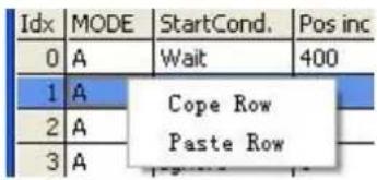
Figure 6-5: Position table copy
Click Copy Row and then click PasteRow in another selected row.
When the position table is completed, click the Write Table button to write it to the controller.
Start the table via DIN with the Start PosTable function. The entry index task is triggered and position flow is started (via StartCond rule).
The DIN AbortPosTable signal (rising edge) or deleting the Start PosTable function configuration in DIN aborts a running position flow after the currently running task is finished.
Position flow is aborted immediately if an error occurs or if the Operation_Mode is changed.

Information
The table in the window is not written to the controller automatically. The button has to be clicked. The table can be read out of the controller and into the window by clicking the Read Table button. A table can be imported from an existing .pft file to the windowby clicking Import Table, and it can be exported from the window to a .pft file by
6.5 Pulse Train mode (-4)
In the pulse mode, the target velocity command is specified via the pulse input with gear ratio.
Table 6-15: Pulse mode
| Panel address | Internal address | Type | Name | Description | Value |
| 6060.00 | Int8 | Operation_Mode | -4 | ||
| d3.34 | 2508.01 | Int16 | Gear_Factor[0] | Gear_ratio=Gear_Factor/Gear_Divider | User defined |
| d3.35 | 2508.02 | Uint16 | Gear_Divider[0] | ||
| 6040.00 | Uint16 | Controlword | See table 6-5 | 0x0F, 0x06 | |
| d3.36 | 2508.03 | Uint8 | PD_CW | Pulse train mode0: CW / CCW1: Pulse / direction2: A / B (incremental encoder) | 0, 1, 2 |
| d3.37 | 2508.06 | Uint16 | PD_Filter | Pulse filter (ms) | User defined |
| d3.38 | 2508.08 | Uint16 | Frequency_Check | Frequency limit (inc/ms), if pulse count (in 1 ms) is greater than Frequency_Check, over frequency error occurs. |
Table 6-16: PD_CW schematic
| Pulse mode Forward Reverse | ||
| P/D | 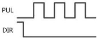 | 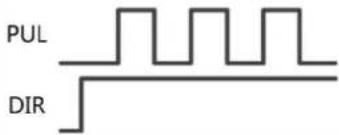 |
| CW/CCW | 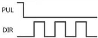 | 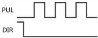 |
| A/B | 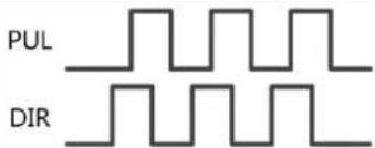 | 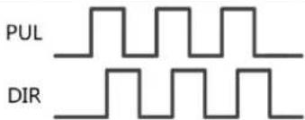 |

Information
Forward means positive position counting's defaulted to the CCW direction. You can set Invert_Dir(607E.00) to 1 in order to invert the direction of motor shaft rotation.
PD_filter effect principle:

line
| Filter TimeFilter Time | Command After Filter | Command Before Filter | | ---------------------- | -------------------- | --------------------- | | 0 | Px0.293 | Px0.707 | | End | Px0.293 | Px0.707 |Figure 6-6: Pulse filter principle
6.5.1 Master-slave mode
The master-slave mode is a type of pulse train mode - PD_CW = 2. The pulse input for the slave controller comes from an external incremental encoder or the encoder output of the master controller. Encoder output (ENCO) signal resolution of the master controller is specified via Encoder_Out_Res.
Table 6-17: Master-slave mode
| Panel address | Internal address | Type | Name | Description | Value |
| 2340.0F | Int32 | Encoder_Out_Res | Specify encoder output pulse number for 1 motor encoder revolution | User defined |
For slave controller parameter setting, please refer to upper introduction of pulse mode.
Wiring between the master and the slave is as follows:
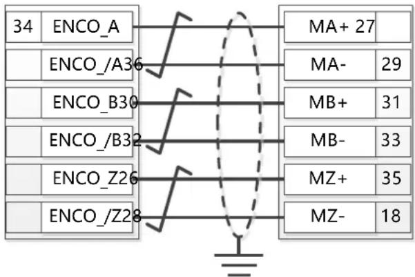
Figure 6-7: Master slave wiring (example: from one CMMB controller to another)
6.6 Homing mode (6)
For some applications, the system needs to start from the same position every time after power on. In the homing mode, the user can specify the system's home position and a zero (starting) position.
Click menu item Controller->Control Modes->Homing definition, and the following window appears:
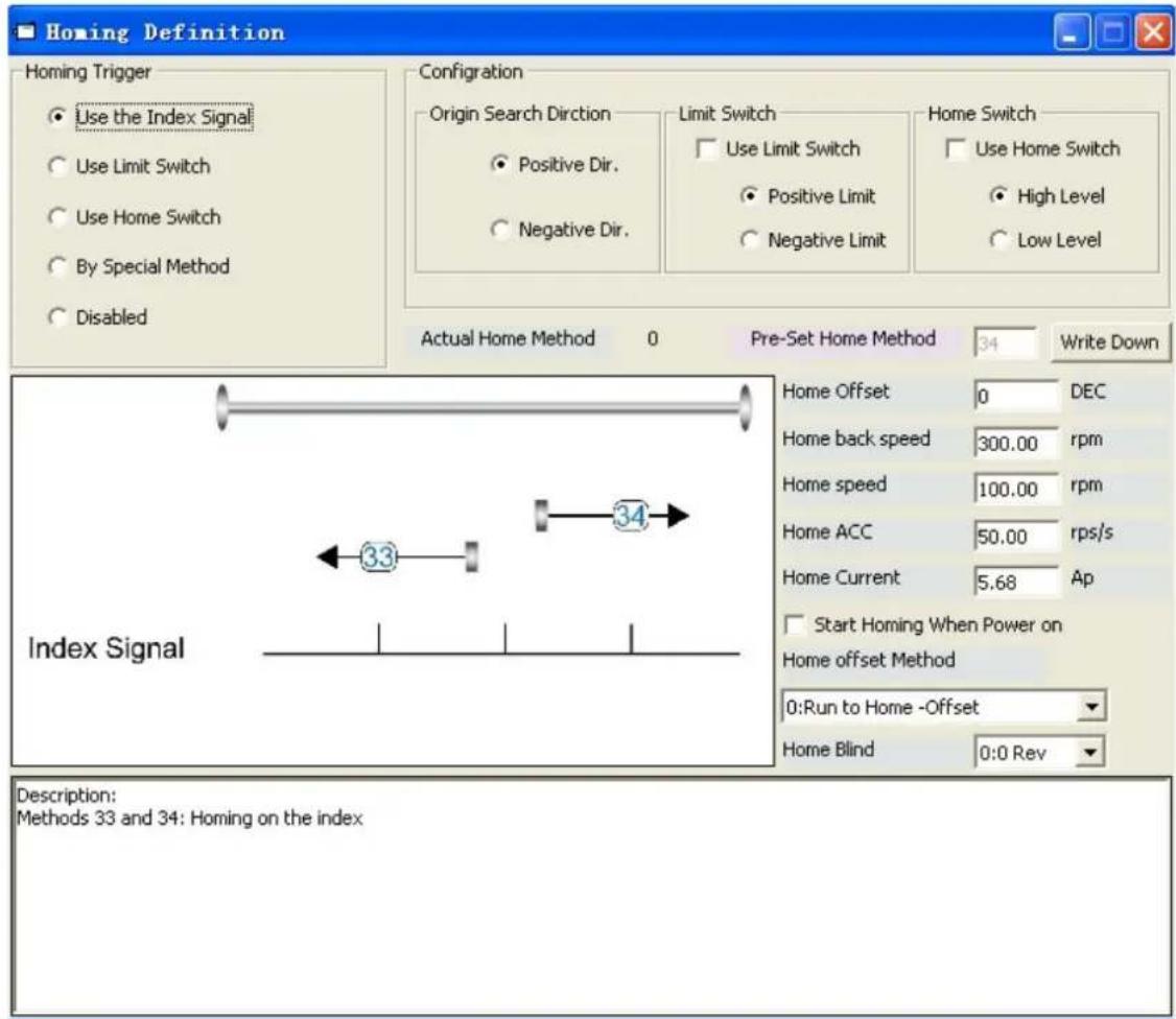
Figure 6-8: Homing settings
Select a home trigger under Homing Trigger. The related items appear in the configuration area. Select a suitable item according to mechanical design and wiring. The Appropriate homing_method then appears in the Pre-Set Home Method box. If Disabled is selected under homing trigger, you enter a number directly to the Pre-Set Home Method field. Click Write Down to set it to the controller.
The corresponding diagram of the Pre-Set Home method appears in the middle area.
All homing mode objects are listed in following table:
Table 6-18: Homing mode
| Panel address | Internal address | Type | Name | Description | Value |
| 607C.00 | Int32 | Home_Offset | Zero position offset to the home position | User defined | |
| 6098.00 | Int8 | Homing_Method | See figure 6-8 | ||
| 6099.01 | Uint32 | Homing_Speed_Switch | Velocity for searching position limit switch / home switch signal | ||
| 6099.02 | Uint32 | Homing_Speed_Zero | Velocity for finding home position and zero position | ||
| 6099.03 | Uint8 Homing_Power_On | 1: Start homing after power on or reboot and first controller enable | 0, 1 | ||
| 609A.00 | Uint32 | Homing_Acceleration | Profile deceleration and acceleration during homing | User defined | |
| 6099.04 | Int16 | Homing_Current | Max. current during homing | ||
| 6099.05 | Uint8 | Home_Offset_Mode | 0: Go to the homing offset point. The actual position will be 0.1: Go to the home trigger point. The actual position will be -homing offset. | 0, 1 | |
| 6099.06 | Uint8 Home_N_Blind | Home blind window0: 0rev1: 0.25rev2: 0.5rev | 0, 1, 2 | ||
| 6060.00 | Int8 | Operation_Mode | 6 | ||
| 6040.00 | Uint16 | Controlword | See table 6-5 | 0x0F->0x1F, 0x06 | |

Note
Homing_Power_On=1 causes the motor to start rotating as soon as the controller is enabled after power on or reboot. Consider all safety issues before using.
Home\_N\_Blind:
If the homing_method needs home signal (position limit / home switch) and index signal, Home_N_Blind function can avoid the homing result being different with the same mechanics, when the Index signal is very close to the home signal. By setting to 1 before homing, the controller detects a suitable blind window for homing automatically. It can be used to assure that homing results are always the same.
During homing, the index signal inside this blind window is ignored after the home signal is found.
Home_N_Blind (0:0rev;1:0.25rev;2:0.5rev) is defaulted to 0. If it's set to 1, it's changed to 0 or 2 after homing depending on the index signal position relative to the homing signal. This parameter needs to be saved. If the mechanical assembly is changed or the motor has been replaced, just set it to 1 again for initial homing.
Table 6-19: Introduction to the Homing_Method
| Homing_Method | Description Schematic | |
| 1 | Homing with negative position limit switch and index pulse | Index Signal 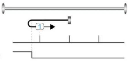 Negative Limit Negative Limit |
| 2 | Homing with positive position limit switch and index pulse | Index SignalPositive Limit | 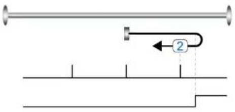 |
| 3 | Homing with home switch and index pulse | Index SignalHome Signal | 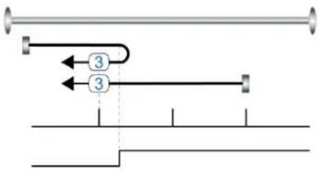 |
| 4 | Homing with home switch and index pulse | Index SignalHome Signal | 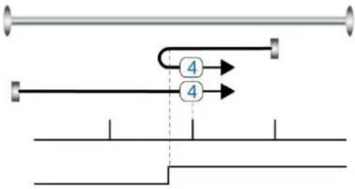 |
| 5 | Homing with home switch and index pulse | Index SignalHome Signal | 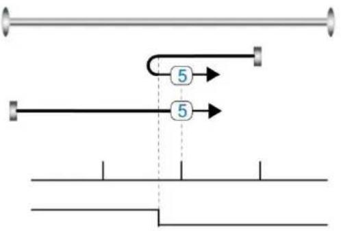 |
| 6 | Homing with home switch and index pulse | 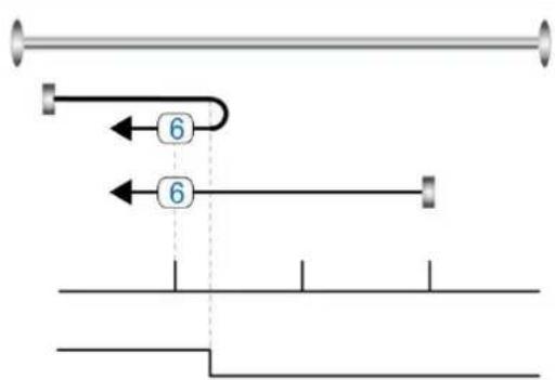 Index SignalHome Signal Index SignalHome Signal | |
| 7 | Homing with positive position limit switch, home switch and index pulse | 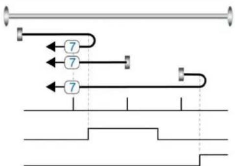 Index SignalHome SignalPositive Limit Index SignalHome SignalPositive Limit | |
| 8 | Homing with positive position limit switch, home switch and index pulse | 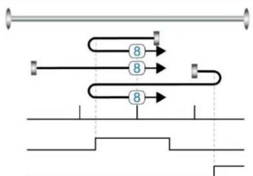 Index SignalHome SignalPositive Limit Index SignalHome SignalPositive Limit | |
| 9 | Homing with positive position limit switch, home switch and index pulse | 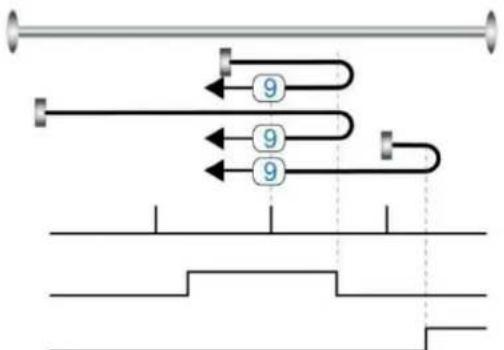 Index SignalHome SignalPositive Limit Index SignalHome SignalPositive Limit | |
| 10 | Homing with positive position limit switch, home switch and index pulse | Index SignalHome SignalPositive Limit | 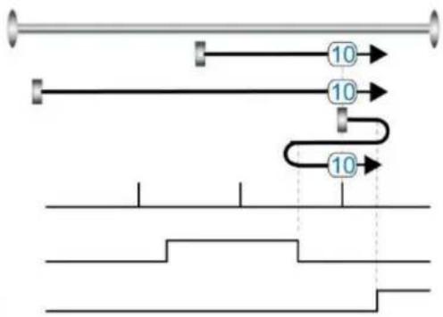 |
| 11 | Homing with negative position limit switch, home switch and index pulse | Index SignalHome SignalNegative Limit | 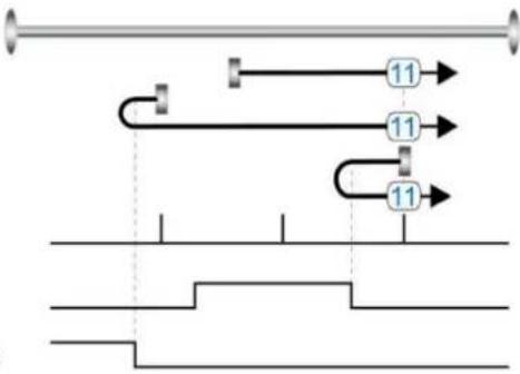 |
| 12 | Homing with negative position limit switch, home switch and index pulse | Index SignalHome SignalNegative Limit | 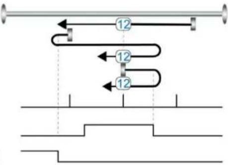 |
| 13 | Homing with negative position limit switch, home switch and index pulse | Index SignalHome SignalNegative Limit | 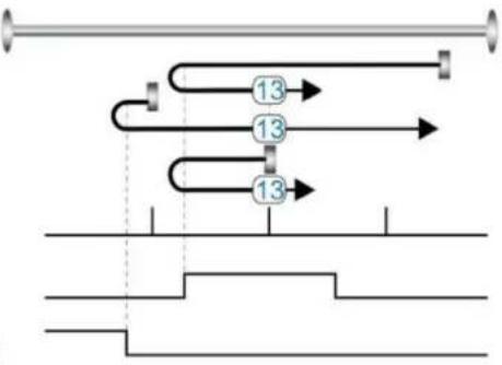 |
| 14 | Homing with negative position limit switch, home switch and index pulse | Index SignalHome SignalNegative Limit | 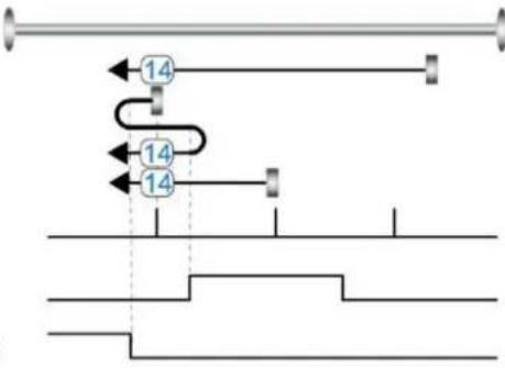 |
| 17 | Homing with negative position limit switch | 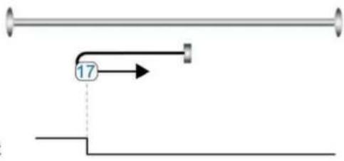 Negative Limit Negative Limit |
| 18 | Homing with positive position limit switch | 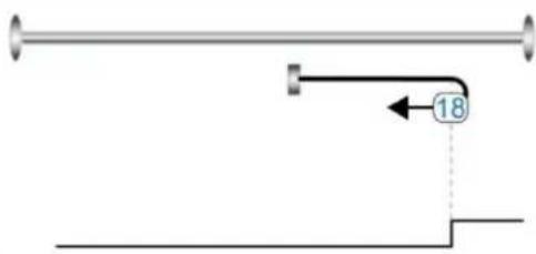 Positive Limit Positive Limit |
| 19 | Homing with home switch | 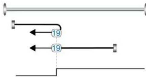 Home Signal Home Signal |
| 20 Homing with home switch | 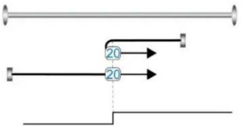 Home Signal Home Signal | |
| 21 Homing with home switch | 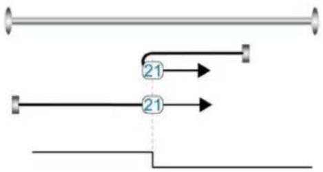 Home Signal Home Signal | |
| 22 Homing with home switch | 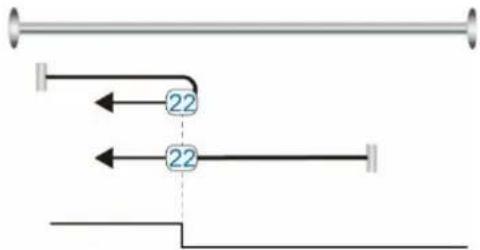 Home Signal Home Signal | |
| 23 | Homing with positive position limit switch and home switch | 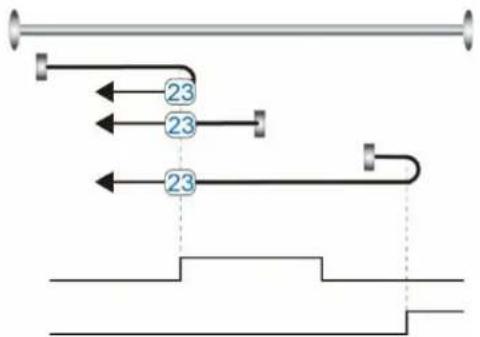 Home SignalPositive Limit Home SignalPositive Limit |
| 24 | Homing with positive position limit switch and home switch | 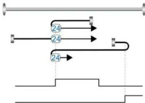 Home SignalPositive Limit Home SignalPositive Limit |
| 25 | Homing with positive position limit switch and home switch |  Home SignalPositive Limit Home SignalPositive Limit |
| 26 | Homing with positive position limit switch and home switch | 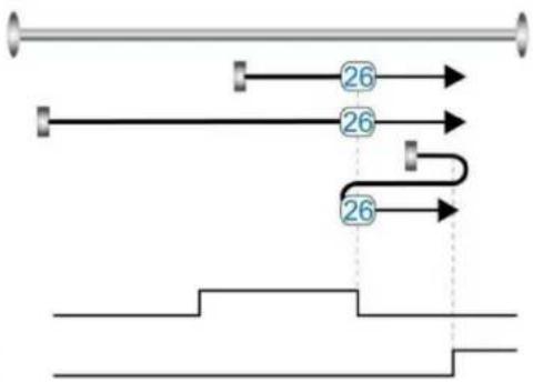 Home SignalPositive Limit Home SignalPositive Limit |
| 27 | Homing with negative position limit switch and home switch | 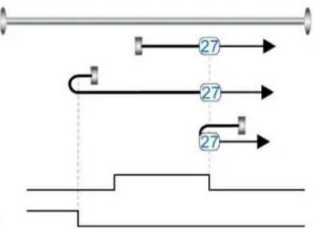 Home SignalNegative Limit Home SignalNegative Limit |
| 28 | Homing with negative position limit switch and home switch | 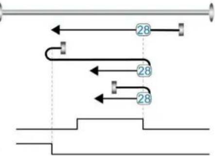 Home SignalNegative Limit Home SignalNegative Limit |
| 29 | Homing with negative position limit switch and home switch | 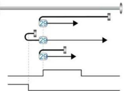 Home SignalNegative Limit Home SignalNegative Limit |
| 30 | Homing with negative position limit switch and home switch | 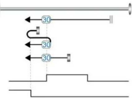 Home SignalNegative Limit Home SignalNegative Limit |
| 33, 34 Homing with index pulse | Index Signal |  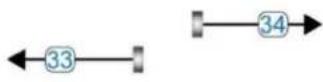  |
| 35 Homing to actual position | ||
| -17, -18 | Homing via mechanical limit | Negative Limit   Positive Limit Positive Limit |
Chapter 7
Tuning of the servo system control
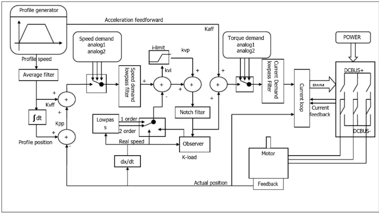
flowchart
graph TD
    A["Profile generator"] --> B["Average filter"]
    B --> C["Profile position"]
    C --> D["+"]
    D --> E["Speed demand analog1 analog2"]
    E --> F["Speed demand lowpass filter"]
    F --> G["+"]
    G --> H["kvi"]
    H --> I["+"]
    I --> J["Notch filter"]
    J --> K["Observer K-load"]
    K --> L["Lowpass s"]
    L --> M["Real speed"]
    M --> N["dx/dt"]
    N --> O["Actual position"]
    O --> P["Motor Feedback"]
    P --> Q["DCBUS-"]
    Q --> R["Current loop"]
    R --> S["Current feedback"]
    S --> T["DCBUS+"]
    T --> U["POWER"]
    U --> V["Acceleration feedforward"]
    V --> W["Profile speed"]
    W --> X["+"]
    X --> Y["Speed demand lowpass filter"]
    Y --> Z["+"]
    Z --> AA["+"]
    AA --> AB["Notch filter"]
    AB --> AC["Observer K-load"]
    AC --> AD["Lowpass s"]
    AD --> AE["Real speed"]
    AE --> AF["Kvi"]
    AF --> AG["+"]
    AG --> AH["+"]
    AH --> AI["Current loop"]
    AI --> AJ["DCBUS-"]
    AJ --> AK["Power"]
Figure 7-1: Servo system control block diagram
Figure 7.1 shows the servo system control block diagram. It can be seen from the figure that the servo system generally includes three control loops: current loop, velocity loop and position loop.
The adjustment process of a servo system is used to set loop gain and filters to match the mechanical characteristics, and finally to prevent the entire system from oscillating, to permit it to follow commands quickly and to eliminate abnormal noise.
7.1 Auto-tuning
The auto-tuning function will try to stimulate the motor and load system by some motions, and get the inertia of the load. If auto-tuning is successful, stiffness will be auto-set according to the inertia ratio.
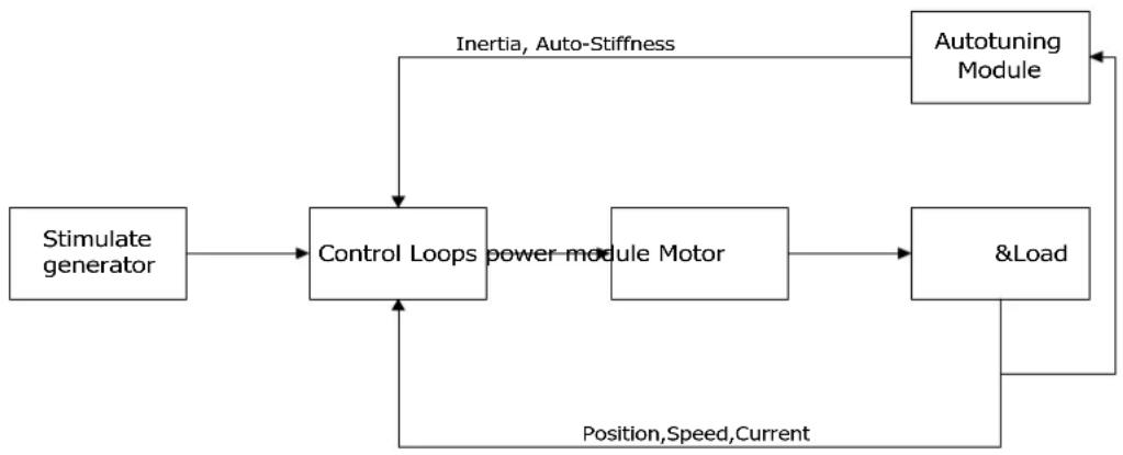
flowchart
graph TD
    A["Stimulate generator"] --> B["Control Loops"]
    B --> C["Power module Motor"]
    C --> D["&Load"]
    D --> E["Autotuning Module"]
    E --> F["Inertia, Auto-Stiffness"]
    F --> B
    B --> G["Position,Speed,Current"]
    G --> B
Figure 7-2: Auto-tuning
Caution: auto-tuning causes the motor to oscillate for about 1 second and the maximum oscillation range is roughly 0.5 rev: make sure that your machine system can withstand this oscillation.
7.1.1 Parameters for auto-tuning
Table 7-1: Auto-tuning function parameters
| Panel address | Internal address | Name | Description | Default | Range | R: readW: writeS: save |
| tn01 | 3040.08 | Stiffness | Range:0-31.Link to stiffness table. | 12 | 0-31 | RWS |
| tn02 3040.0B Inertia_Ratio | Inertia_Ratio=(J_Load+J_Motor)*10/J_Motor | 30 | 10-500 | RWS | ||
| tn03 | 3040.01 | Tuning_Method | Write 1 starts tuning and inertia measurement. If 1 appears after tuning, tuning has been successful. | RW | ||
| tn04 | 3040.06 | Safe_Dist | Unit: 0.01revThis parameter indicates the theoretical range of motion during auto-tuning.Setting this parameter to a higher value reduce disturbance influence and makes results more reliable, but alsoresults in greater oscillation. | 22 0-40 RWS | ||
7.1.2 Start of auto-tuning
Via the LED panel (see chapter 4.3):
Open the tunE menu in the LED panel and go to tn03.
Write 1 to tn03. The motor oscillates with a small amplitude, the oscillation lasts less than 1s.
If tn03 remains at 1 after auto-tuning is done, auto-tuning has been successful. Otherwise it has failed (see 7.1.3).
Via PC software:
Click CMMB Configurator menu item Controller->Operation Modes->Auto-tuning
| NUM | Index | Type | Name | Value | Unit |
| 0 | 304001 | int8 | Tuning_Method | 0 | DEC |
| 1 | 304006 | uint16 | Safe_Dist | 22 | DEC |
| 2 | 304007 | int32 | EASY KLOAD | 992 | DEC |
| 3 | 304009 | int8 | Inertia_Get_Result | 0 | DEC |
| 4 | 304008 | uint8 | Stiffness | 12 | DEC |
| 5 | 30400B | int16 | Inertia_Ratio | 30 | DEC |
| 6 | 304105 | uint8 | WriteFUN_CTL | 0 | DEC |
Figure 7-3: Auto-tuning
Write 1 to TUN CTL (3041.05), and then write 1 to Tuning Method (3040.01). The motor oscillates for less than 1s and the results appear. If Inertia_Get_Result(3040.09) = 1 the tuning process was able to obtain a valid Inertia_Ratio(3040.0B). Otherwise the tuning process has failed, see 7.1.3 for hints. Write 1 to the Tuning_Method(3041.01) again to check that the Inertia_Ratio result is reproducible. If not, carefully increase
Safe_Dist(3040.06) to get more precise results. If the machine shakes too much, reduce_Safe_Dist to reduce oscillation.
7.1.3 Problems with auto-tuning
If the tuning process has failed, the error result of tn03 / Inertia_Get_Result(3040.09) tells the fail-reason:
0: The controller could not be enabled by any reason.
-1: Inertia cannot be measured due to too little motion or too little current.
-2: The measured inertia result is outside the valid range.
-3: The resulting Inertia_Ratio value is greater than 250 (inertia ratio > 25). This is a possible result, but the control loop will not be tuned.
-4: The resulting Inertia_Ratio value is larger than 500 (inertia ratio > 50). This is an uncertain result. In the cases 0, -1, -2, -4 Inertia_Ratio is set to 30, in the case -3 Inertia_Ratio is set as measured, Stiffness is set to 7-10
In any fail case the control loop parameters are set to Inertia_Ratio of 30 and the set Stiffness values. To make the measured Inertia_Ratio of case -3 become effective, the value of tn02 must be confirmed by SET or the Inertia_Ratio(3040.0B) must be written once.

Information
Reasons for the failure of auto-tuning:
- Incorrect wiring of the CMMB servo system
● DIN function Pre_Enable is configured but not active
● Too much friction or external force is applied to the axis to be tuned
● Too big backlash in the mechanical path between the motor and the load - Inertia ratio is too large
● The mechanical path contains too soft components (soft belts or couplings)
If none of those reasons can be encountered, Safe_Dist may be increased in order to remedy problems. If auto-tuning still fails, manual tuning (see chapter 7.2) is advised to be executed.
7.1.4 Adjustment after auto-tuning.
After auto-tuning the stiffness is set to a value in the range of 4 to 12. The greater the inertia ratio, the smaller the stiffness value will be.
Table 7-2: Stiffness and control loop settings
| Stiffness | Kpp/[0.01Hz] | Kvp/[0.1Hz] | Output filter [Hz] |
| 0 | 70 | 25 | 18 |
| 1 | 98 | 35 | 24 |
| 2 | 139 | 50 | 35 |
| 3 | 195 | 70 | 49 |
| 4 | 264 | 95 | 66 |
| 5 | 334 | 120 | 83 |
| 6 | 389 | 140 | 100 |
| 7 | 473 | 170 | 118 |
| 8 | 556 | 200 | 146 |
| Stiffness | Kpp/[0.01Hz] | Kvp/[0.1Hz] | Output filter [Hz] |
| 16 | 1945 | 700 | 464 |
| 17 | 2223 | 800 | 568 |
| 18 | 2500 | 900 | 568 |
| 19 | 2778 | 1000 | 733 |
| 20 | 3334 | 1200 | 733 |
| 21 | 3889 | 1400 | 1032 |
| 22 | 4723 | 1700 | 1032 |
| 23 | 5556 | 2000 | 1765 |
| 24 | 6389 | 2300 | 1765 |
| 9 | 639 | 230 | 164 |
| 10 | 750 | 270 | 189 |
| 11 | 889 | 320 | 222 |
| 12 | 1056 | 380 | 268 |
| 13 | 1250 | 450 | 340 |
| 14 | 1500 | 540 | 360 |
| 15 | 1667 | 600 | 392 |
Stiffness should be adjusted according to the actual requirement.
If response is too slow → increase stiffness. If oscillation or noise increases → reduce stiffness.
If the command from the controller (e.g. PLC) is unreasonable or inappropriate for the machine, some filters should be modified in order to reduce oscillation (see chapter 7.3 manual tuning).

Information
When the stiffness setting or the inertia ratio increases Kvp to a value of greater than 4000, it's not useful to increase stiffness any more, and bandwidth will be decreased if the inertia ratio is further increased. If changing stiffness via communication, WriteFUN_CTL(3041.05) must be set to 1 first, and be set back to 0 after stiffness has been changed.
7.2 Manual tuning
If the auto-tuning function does not support the actual application, or if the application has a gap, inertia changes or a very soft connection, manual tuning is the right choice.
The manual tuning process makes use of test motion. Match the controller to the actual application on the basis of experience with the application and a given scope of data by changing loop gain and filter settings.
Since current loop parameters are calculated internally based on the motor parameters, there is normally no need to set current loop parameters manually.
7.2.1 Tuning of the velocity loop
Steps required for adjustment:
Ensure limiting of velocity loop bandwidth
Velocity loop bandwidth limits position loop bandwidth and thus adjustment of velocity loop bandwidth is important.
Limitation of velocity loop bandwidth can be judged from several viewpoints.
1) According to oscillation and noise sensed with the finger and the ears: This method is based on experience, but it's efficient. The user can listen to or touch the machine, at the same time increasing and reducing the kvp. When an acceptable maximum kvp value is found, the current setting can be specified as the maximum velocity loop bandwidth.
2) According to the scope image: The user can create a jump command for velocity control and sample actual velocity and current while changing kvp. The right velocity curve should quickly fulfil the command without oscillation and unusual noise.
Table 7-3: List of velocity loop parameters
| Panel address | Internal address | Name | Description | Default | Range |
| 60F901 | Kvp[0] | Proportional velocity loop gainCan be displayed in Hz in the PC tool can if the inertia ratio is right. | / 1-32767 | ||
| d2.01 | 2FF00A | Velocity_BW | Changing this parameter changes kvp[0] by the inertia ratio. | / 1-700 | |
| 60F902 | Kvi[0] | Integral velocity loop gain | / | 0-1023 | |
| 60F907 | Kvi/32 | Integral velocity loop gain of in a smaller unit of measure | / 0-32767 | ||
| d2.02 2FF019 | Kvi_Mix | Writing this parameter sets kvi[0] to 0, and the value is set to kvi/32. | / 0-16384 | ||
| d2.05 60F905 | Speed_Fb_N | Used to set Velocity feedback filter bandwidthFilter bandwidth=100+Speed_Fb_N*20 | 25 0-45 | ||
| d2.06 60F906 | Speed_Mode | Used to set the velocity feedback mode0: 2nd order FB LPF1: Directly feedback the original velocity2: Velocity feedback after velocity observer4: Velocity feedback after 1^st order LPF10: Velocity feedback after 2^nd order LPF and the velocity command is filtered by a 1^st order LPF. Both filters have the same bandwidth. 11: The velocity command is filtered by a 1^st order LPF12: Velocity feedback after velocity observer, the velocity command is filtered by a 1^st order LPF14: Velocity feedback after 1^st order LPF and the velocity command is filtered by a 1^st order LPF. Both filters have the same bandwidth | 1 / | ||
| 60F915 | Output_Filter_N | A 1^st order lowpass filter in the forward path of the velocity loop | 1 1-127 | ||
| 60F908 | Kvi_Sum_Limit | Integral output limit of the velocity loop | / | 0-2^15 |
Velocity feedback filter adjustment
The velocity feedback filter can reduce noise that comes from the feedback path, e.g. reduce encoder resolution noise. The velocity feedback filter can be configured as 1^st and 2^nd order via the Speed_Mode for different applications. The 1^st order filter reduces noise to a lesser extent, but its also results in less phase shifting so that velocity loop gain can be set higher. The 2^nd order filter reduces noise to a greater extent, but its also results in more phase shifting so that velocity loop gain can be limited.
Normally, if the machine is stiff and light, we can use the 1st feedback filter or disable the feedback filter. If the machine is soft and heavy, we can use the 2^nd order filter.
If there's too much motor noise when velocity loop gain is adjusted, velocity loop feedback filter parameter Speed_Fb_N can be reduced accordingly. However, velocity loop feedback filter bandwidth F must be more than twice as large as the velocity loop bandwidth. Otherwise, it may cause oscillation. Velocity loop feedback filter bandwidth F=Speed_Fb_N*20+100 [Hz].
Output filter adjustment
The output filter is a 1^st order torque filter. It can reduce the velocity control loop to output high frequency torque, which may stimulate overall system resonance.
The user can try to adjust Output_Filter_N from small to large in order to reduce noise.
The filter bandwidth can be calculated using the following formula.
$$ \frac {1}{2} \frac {\ln \left(1 - \frac {1}{O u t p u t _ F i l t e r N}\right)}{T s \pi}, T s = 6 2. 5 u s $$
Velocity loop bandwidth calculation
Use the following formula to calculate velocity loop bandwidth:
$$ k v p = \frac {1 . 8 5 3 3 5 8 0 8 0 1 0 ^ {5} J \pi^ {2} F b w}{I _ {\text { Max }} k t \text { encoder }} $$
kt motor torque constant, unit: Nm/Arms*100
J inertia, unit: kg*m^2*10^6
Fbw Velocity loop bandwidth, unit: Hz
Imax max motor current I_max(6510.03) as DEC value
encoder resolution of the encoder
Integral gain adjustment
Integral gain is used to eliminate static error. It can boost velocity loop low frequency gain, and increased integral gain can reduce low frequency disturbance response.
Normally, if the machine has considerable friction, integral gain (kvi) should be set to a higher value.
If the entire system needs to respond quickly, integral should be set to a small value or even 0, and the gain switch should be used.
Adjust Kvi\_sum\_limit
Normally the default value is fine. This parameter should be added if the application system has a big extend force, or should be reduced if the output current is easily saturation and the saturation output current will cause some low frequency oscillation.
7.2.2 Tuning of the position loop
Table 7-4: List of position loop parameters
| Panel address | Internal address | Name | Description | Defaults | Range |
| d2.07 60FB | B.01 Kpp[0] | Proportional position loop gain.Used to set the position loop response.unit: 0.01Hz | 10 0-32767 | ||
| d2.08 | 2FF0.1A | K_Velocity_FF‰ | 0 means no feedforward, 1000 means 100% feedforward. | 1000 | 0-4000 |
| d2.09 2FF0 | 1B K_Acc_FF‰ | The unit only is right if the inertia ratio is correctly set.If the inertia ratio is unknown, set K_Acc_FF(60FB.03) instead. | / | 0-4000 | |
| d2.26 | 60FB.05 | Pos_Filter_N | The time constant of the position demand LPF unit: ms | 1 | 1-255 |
| d2.25 2FF0.0E | Max_Following_Error_16 | Maximum allowable error, Max_Following_Error(6065.00) = 100 * Max_Following_Error_16 | 5242 / |
Position loop proportional gain adjustment
Increasing position loop proportional gain can improve position loop bandwidth, thus reducing positioning time and following error, but setting it too high will cause noise or even oscillation. It must be set according to load conditions. Kpp = 103 * Pc_Loop_BW, Pc_Loop_BW is position loop bandwidth. Position loop bandwidth cannot exceed velocity loop bandwidth. Recommended velocity loop bandwidth: Pc_Loop_BW<Vc_Loop_BW / 4, Vc_Loop_BW.
Position loop velocity feedforward adjustment
Increasing the position loop velocity feedforward can reduce position following error, but can result in increased overshooting. If the position command signal is not smooth, reducing position loop velocity feedforward can reduce motor oscillation.
The velocity feedforward function can be treated as the upper controller (e.g. PLC) have a chance to directly control the velocity in a position operation mode. In fact this function will expend part of the velocity loop response ability, so if the setting can't match the position loop proportional gain and the velocity loop bandwidth, the overshot will happen.
Besides, the velocity which feedforward to the velocity loop may be not smooth, and with some noise signal inside, so big velocity feedforward value will also amplified the noise.
Position loop acceleration feedforward
It is not recommended that the user adjust this parameter. If very high position loop gain is required, acceleration feedforward K_Acc_FF can be adjusted appropriately to improve performance.
The acceleration feedforward function can be treat as the upper controller (e.g. PLC) have a chance to directly control the torque in a position operation mode. In fact this function will expend part of the current loop response ability, so if the setting can't match the position loop proportional gain and the velocity loop bandwidth, the overshot will happen.
Besides, the acceleration which feedforward to the current loop can be not smooth, and with some noise signal inside, so big acceleration feedforward value will also amplified the noise.
Acceleration feedforward can be calculated with the following formula:
ACC_%=6746518/ K_Acc_FF/ EASY_KLOAD*100
ACC_%: the percentage which will be used for acceleration feedforward.
K_Acc_FF(60FB.03): the final internal factor for calculating feedforward.
EASY_KLOAD(3040.07): the load factor which is calculated from auto-tuning or the right inertia ratio input.

Information
The smaller the K_Acc_FF, the stronger the acceleration feedforward.
Smoothing filter
The smoothing filter is a moving average filter. It filters the velocity command coming from the velocity generator and makes the velocity and position commands more smooth. As a consequence, the velocity command will be delayed in the controller. So for some applications like CNC, it's better not to use this filter and to accomplish smoothing with the CNC controller.
The smoothing filter can reduce machine impact by smoothing the command. The Pos_Filter_N parameter defines the time constant of this filter in ms. Normally, if the machine system oscillates when it starts and stops, a larger Pos_Filter_N is suggested.
Notch filter
The notch filter can suppress resonance by reducing gain around the resonant frequency.
Antiresonant frequency=Notch_N*10+100
Setting Notch_On to 1 turns on the notch filter. If the resonant frequency is unknown, the user can set the maximum value of the d2.14 current command small, so that the amplitude of system oscillation lies within an acceptable range, and then try to adjust Notch_N and observe whether the resonance disappears.
Resonant frequency can be measured roughly according to the Iq curve when resonance occurs on the software oscilloscope.
Table 7-5: Notch filter list
| Panel address | Internal address | Name | Description | Default | Range |
| d2.03 60F | 9.03 Notch_N | Used to set the frequency of the internal notch filter to eliminate mechanical resonance generated when the motor drives the machine. The formula is F=Notch_N*10+100. For example, if mechanical resonance frequency F=500 Hz, the parameter setting should be 40. | 45 0-90 | ||
| d2.04 60F | 9.04 Notch_On | Used to turn on or turn off the notch filter.0: Turn on the notch filter1: Turn off the notch filter | 0 0-1 |
7.3 Factors which influence tuning results
The control command is created by the upper controller (e.g. PLC):
The control command should be smooth as much as possible, and must be correct. For example, the control command should not create the acceleration commands (inside the position commands) that the motor cannot provide. Also, the control command should follow the bandwidth limit of the control loop.
The machine design:
In the actual application, performance is normally limited by the machine. Gaps in the gears, soft connection in the belts, friction in the rail, resonance in the system – all of these can influence final control performance. Control performance affects the machine's final performance, as well as precision, responsiveness and stability. However, final machine performance is not only determined by control performance.
Chapter 8 Alarms and troubleshooting
Alarm code numbers flash at the panel when the controller generates an alarm.
If you need more detailed information about errors and error history, please connect the controller to the PC via RS232 and refer to chapter 5.7.
Table 8-1: Alarm codes of Error_State1
| Alarm | Name | Reason | Troubleshooting |
| FFF.F | Wrong motor model | The current motor type is different from the motor type which is saved in the controller. | Method 1: Access EA01 via the KEY, and confirm motor type, then access EA00, set 2.Method2: Access EASY_MT_TYPE (0x304101) via PC software, confirm the value, then save the parameter. |
| 000.1 Extended Error | Errors occurs in Error_State2 | Press the SET key to enter Error_State2 (d1.16), read the error bit, check the error meaning in table 8-2. | |
| 000.2 | Encoder not connected | The encoder wiring is incorrect or disconnected. | Use a multimeter to check connection of the encoder signal cable |
| 000.4 | Encoder internal | Internal encoder error or the encoder is damaged. | 1.Access panel address d3.51 Encoder_OP by KEY and set 1.2.Try to reset the controller error. If error persists, replace the motor. |
| 000.8 | Encoder CRC | Encoder CRC error | Make sure the equipment is well grounded |
| 001.0 | Controller Temperature | The temperature of controller's power module has reached the alarm value. | Improve the cooling environment of the controller. |
| 002.0 Overvoltage | Supply power voltage exceeds the allowable input voltage rangeIn case of emergency stop, there is no external braking resistor or braking. | Check to see if supply power voltage is unstable and if a suitable braking resistor is connected. | |
| 004.0 Undervoltage | The power voltage input is lower than the low voltage protection alarm value. | Check to see if supply power voltage is unstable. | |
| 008.0 Overcurrent | Instantaneous current exceeds the overcurrent protection value. | Check the motor cable for short circuits.Replace the controller. | |
| 010.0 Chop Resistor | The braking resistor is overloaded or it's parameters are not set correctly. | Set the resistance and power of the external braking resistor through d5.04 and d5.05. | |
| 020.0 | Following Error | The actual following error exceeds the setting value of Max_Following_Error.1. Stiffness of control loop is too small.2.The controller and motor together can't match the requirement of the application.3. Max_Following_Error (d2.25) is too small.4. feedforward settings are not feasible.5. Wrong motor wiring. | Check and solve based on the reasons. |
| 040.0 | Low Logic Voltage | Logic power voltage is too low. | Check to see if logic power voltage is unstable. |
| 080.0 | Motor or controller IIIt | The brake is not released when the motor shaft is rotatingMachine equipment stuck or excessive friction.Duty cycle of motor overload exceeds the motor rated performance | Measure the brake terminal voltage is right and the brake is released when the controlleris enabled.Eliminate the problem of mechanical sticking, add lubricate.Reduce the acceleration or load inertia. |
| 100.0 | Over frequency | External input pulse frequency is too high. | Reduce pulse frequency.Increase the value of Frequency_Check (d3.38). |
| 200.0 | Motor temperature | The motor temperature exceeds the specified value. | Reduce ambient temperature of the motor and improve cooling conditions or reduce acceleration and deceleration or reduce load. |
| 400.0 | Encoder information | 1.Communication is incorrect when the encoder is initialized.2.The encoder type is wrong, e.g. an unknown encoder is connected.3.The data stored in the encoder is wrong.4.The controller can't support the current encoder type. | Check and solve according to the reasons. |
| 800.0 EEPROM data | Data is damaged when the power is turned on and data is read from the EEPROM. | Data is damaged when data is read from the EEPROM when the power is turned on. | |
Table 8-2: Alarm codes of Error_State2 (extended)
| Alarm | Name | Reason | Trouble shooting |
| 000.1 | Current sensor | Current sensor signal offset or ripple too big | Circuit of current sensor is damaged, please contact the supplier. |
| 000.2 | Watchdog | Software watchdog exception | Please contact the supplier and try to update the firmware. |
| 000.4 | Wrong interrupt | Invalid interrupt exception | Please contact the supplier and try to update the firmware. |
| 000.8 | MCU ID | Wrong MCU type detected | Please contact the supplier. |
| 001.0 | Motor configuration | Motor type is not auto-recognized, no motor data in EEPROM / motor never configured | Install a correct motor type to the controller and reboot. |
| 010.0 | External enable | DIN function "pre_enable" is configured, but the input is inactive when the controller is enabled or should become enabled | Solve according to the reason. |
| 020.0 | Positive limit | Positive position limit (after homing), position limit only causes error when Limit_Function (2010.19) is set to 0. | Exclude the condition which causes the limit signal |
| 040.0 | Negative limit | Negative position limit (after homing), position limit only causes error when Limit_Function (2010.19) is set to 0. | Exclude the condition which causes the limit signal |
| 080.0 | SPI internal | Internal firmware error in SPI handling | Please contact the supplier. |
| 200.0 | Closed loop direction | Different direction between motor and position encoder | Change the encoder counting direction |
| 800.0 | Master counting | Master encoder counting error | Ensure that the ground connection and the encoder shield work well. |
Chapter 9 List of CMMB series motor controller parameters
9.1 F001
This panel menu contains all controller values which can be shown by the LED display when it's in the monitor mode (see 4.2) and no error or warning is shown. On the LED panel, select the panel address of the value to be displayed and press SET. After leaving the menu, the selected value is displayed. To make this selection permanent it must be saved through d2.00 in F002.
Table 9-1-1: Panel F001
| Panel address | Internal address | Name | Description | Default | Range | R/W/S |
| F001 2FF00408 Key_Address_F001 | Internal value Panel value0 d1.002 d1.024 d1.04... ...For d1.xx meaning please refer to following table 9-1-2 | 25 / RWS | ||||
Table 9-1-2: Panel F001 setting
| Panel address | Internal address | Name | Description | Default | Range | RWS |
| d1.00 | 2FF00F20 | Soft_Version_LED | Firmware version, display at the LED. | / | / | R |
| d1.02 | 2FF01008 | Motor_IIt_Rate | Displays the rate of real iit and max iit of the motor. | 0 | 0-100% R | |
| d1.04 2FF01108 Driver_IIt_Rate | Display the rate of real iit and max iit of the controller. | 0 | 0-100% R | |||
| d1.06 | 2FF01208 | Chop_Power_Rate | Display the rate of real power and rated power of the chopper. | 0 | 0-100% R | |
| d1.08 | 60F70B10 | Temp_Device | temperature of controller, unit: °C, | / | / R | |
| d1.09 | 60F71210 | Real_DCBUS | DC bus voltage, unit: V, | / | / | R |
| d1.11 | 20100A10 | Din_Real | Status of physical inputBit 0: Din 1Bit 1: Din 2Bit 2: Din 3... | / | / R | |
| d1.12 | 20101410 | Dout_Real | Bit 0: Dout 1Bit 1: Dout 2Bit 2: Dout 3... | / | / R | |
| d1.13 | 2FF01610 | AN_V1 | analog signal 1 voltage, unit 0.01V | / | / | R |
| d1.14 | 2FF01710 | AN_V2 | analog signal 2 voltage, unit 0.01V | / | / | R |
| d1.15 | 26010010 | Error_State | See chapter 5.7, table5-7 | 0 | 0-65535 | R |
| d1.16 | 26020010 | Error_State2 | See chapter 5.7, table5-8 | 0 | 0-65535 | R |
| d1.17 | 60410010 | Status word | Status word of controller | / | / | R |
| d1.18 | 60610008 | Operation_Mode_Buff | Operation mode in buffer | 0 | / | R |
| d1.19 | 60630020 | Pos_Actual | Actual position of motor | 0 | -2^31-2^31-1 | R |
| d1.20 | 60FB0820 | Pos_Error | Following error of position | 0 | -2^31-2^31-1 | R |
| d1.21 | 25080420 | Gear_Master | Input pulse amount before electronic gear | 0 | -2^31-2^31-1 | R |
| d1.22 25080520 Gear_Slave | Execute pulse amount after electronic gear | 0 | -2^31-2^31-1 | R | ||
| d1.25 | 2FF01410 | Real_Speed_RPM | Real speed, unit: rpm | 0 | 0-5000 | R |
| d1.26 | 60F91910 | Real_Speed_RPM2 | Real speed, unit: 0.01rpm | 0 | -10-10 | R |
| d1.28 | 60F60C10 | CMD_q_Buff | q current command buffer | 0 | -2048-2047 | R |
| d1.29 | 2FF01800 | I_q_Arms | Real current in q axis, unit 0.1Arms | 0 | / | R |
| d1.48 26800010 Warning_Word | warning status word of the encoder:Bit 0: Battery WarningBit 1: Mixed WarningBit 2: Encoder Busy | 0 0-7 R | ||||
| d1.49 | 30440008 | Cur_IndexofTable | Range: 0-31, current index in the position table | 0 0-31 | R | |
9.2 F002
This panel menu contains parameters for the control loop settings.
Controller->Panel Menu->Control Loop Setting(F002)
Table 9-2: Panel F002
| Panel address | Internal address | Name | Description | Default | Range | RWS |
| d2.00 | 2FF00108 | Store_Data | Save or init parameters1: save control parameters10: init control parameters | 0 0-255 | RW | |
| d2.01 2FF00A10 Velocity_BW | Bandwidth of the velocity loop, unit: Hz. | / | 1-700 | RWS | ||
| d2.02 | 2FF01910 | Kvi_Mix | Integral gain of the velocity loop, as a combination of 32*Kvi(60F9.02) + Kvi/32(60F9.07). When written, it sets Kvi(60F9.02)=0 and the value goes to Kvi/32(60F9.07). | / | 0- 65535 | RWS |
| d2.03 60F90308 Notch_N | Notch filter frequencyBW=Notch_N*10+100[Hz] | 45 | 0-127 | RWS | ||
| d2.04 | 60F90408 | Notch_On | Notch filter enable | 0 | 0-1 | RWS |
| d2.05 60F | 90508 Speed_Fb_N | Bandwidth of velocity feedback filter BW=Speed_Fb_N*20+100[Hz] | 25 0-45 | RWS | ||
| d2.06 60F | 90608 Speed_Mode | Default: 0, means using 2^nd order low pass filter0: 2^nd order FB LPF1: No FB LPF2: Observer FB4: 1st order FB LPF10: 2nd LPF+SPD_CMD FT11: SPD_CMD FT12: SPD_CMD FT+Observer14: 1st LPF+Observer | 1 0-255 | RWS | ||
| d2.07 | 60FB0110 | Kpp | Kp of position loop.unit:0.01Hz | 1000 | 0-32767 | RWS |
| d2.08 | 2FF01A10 | K_Velocity_FF‰ | Feedforward of position loop, unit: 0.1% | 0 0-1500 | RWS | |
| d2.09 2FF | 01B10 K_Acc_ | FF‰ | Acceleration forward of position loop, unit: 0.1% | 0 0-1500 | RWS | |
| d2.12 | 60F60110 | Kcp | Kp of current loop | / | 1-32767 | RWS |
| d2.13 | 60F60210 | Kci | Ki of current loop | / | 0-1000 | RWS |
| d2.14 2FF | 01C10 CMD_q | Max_Arms | Maximum current command in q axis unit: 0.1Arms | / 0-32767 | RWS | |
| d2.15 | 60F60310 | Speed_Limit_Factor | A factor for limiting max velocity in the torque mode | 10 0-1000 | RWS | |
| d2.16 607 | E0008 Invert_Dir | Invert motion0: CCW is positive direction1: CW is positive direction | 0 0 - 1 | RWS | ||
| d2.24 | 60800010 | Max_Speed_RPM | Motor's max speed unit: rpm | 5000 | 0 - 15000 | RWS |
| d2.25 2FF | 00E10 | Max_Following_Error_16 | Max_Following_Error=100*Max_Following_Error_16 | 5242 | 1 - 32767 | RWS |
| d2.26 | 60FB0510 | Pos_Filter_N | Average filter parameter | 1 | 1 - 255 | RWS |
| d2.27 | 20101810 | Zero_Speed_Window | Dout function Zero_Speed is active eif the actual speed is equal or less than this valueunit: inc/ms | 0 0 - 655 | 35 RWS | |
9.3 F003
This panel menu contains parameter for the configuration of analog and digital I/O functions. Controller->Panel Menu->F003 DI/DO & Operation Mode Setting(F003)
Table 9-3: Panel F003 parameters
| Panel address | Internal address | Name | Description | Default | Range | RWS |
| d3.00 2FF | 00108 Store_Data | Save or init parameters1: save control parameters10: init control parameters | 0 0-255 | RW | ||
| d3.01 | 20100310 | Din1_Function | See chapter 6.1, table 6-1 | 0x0001 | 0-65535 | RWS |
| d3.02 | 20100410 | Din2_Function | See chapter 6.1, table 6-1 | 0x0002 | 0-65535 | RWS |
| d3.03 | 20100510 | Din3_Function | See chapter 6.1, table 6-1 | 0x2000 | 0-65535 | RWS |
| d3.04 | 20100610 | Din4_Function | See chapter 6.1, table 6-1 | 0x0010 | 0-65535 | RWS |
| d3.05 | 20100710 | Din5_Function | See chapter 6.1, table 6-1 | 0x0020 | 0-65535 | RWS |
| d3.06 | 20100810 | Din6_Function | See chapter 6.1, table 6-1 | 0 | 0-65535 | RWS |
| d3.07 | 20100910 | Din7_Function | See chapter 6.1, table 6-1 | 0x0040 | 0-65535 | RWS |
| d3.10 200 | 00008 Switch_On_Auto | 0: no operation1: auto-enable when logic power-up.Can be set only if the DIN function enable is not defined. | 0 0-255 | RWS | ||
| d3.11 | 20100F10 | Dout1_Function | See chapter 6.1, table 6-2 | 0x0001 | 0-65535 | RWS |
| d3.12 | 20101010 | Dout2_Function | See chapter 6.1, table 6-2 | 0x0010 | 0-65535 | RWS |
| d3.13 | 20101110 | Dout3_Function | See chapter 6.1, table 6-2 | 0x0004 | 0-65535 | RWS |
| d3.14 | 20101210 | Dout4_Function | See chapter 6.1, table 6-2 | 0x0008 | 0-65535 | RWS |
| d3.15 | 20101310 | Dout5_Function | See chapter 6.1, table 6-2 | 0x0002 | 0-65535 | RWS |
| d3.16 | 20200D08 | Din_Mode0 | Operation mode channel 0: select via input port | -4 | -128-127 | RWS |
| d3.17 | 20200E08 | Din_Mode1 | Operation mode channel 1: select via input port | -3 | -128-127 | RWS |
| d3.18 202 | 00910 Din_Speed0_RPM | See chapter 6.2.2, table 6-8 unit: rpm | 0 | -32768-32767 | RWS | |
| d3.19 | 20200A10 | Din_Speed1_RPM | See chapter 6.2.2, table 6-8 unit: rpm | 0 | -32768-32767 | RWS |
| d3.20 | 20200B10 | Din_Speed2_RPM | See chapter 6.2.2, table 6-8 unit: rpm | 0 | -32768-32767 | RWS |
| d3.21 | 20200C10 | Din_Speed3_RPM | See chapter 6.2.2, table 6-8 unit: rpm | 0 | -32768-32767 | RWS |
| d3.22 | 25020110 | Analog1_Filter | Filter parameter of analog signal 1 | 5 | 1-127 | RWS |
| d3.23 | 2FF01D10 | Analog1_Dead_V | Unit: 0.01V | 0 | -1000-1000 | RWS |
| d3.24 | 2FF01E10 | Analog1_Offset_V | Unit: 0.01V | 0 | -1000-1000 | RWS |
| d3.25 | 25020410 | Analog2_Filter | Filter parameter of analog signal 2 | 5 | 1-127 | RWS |
| d3.26 | 2FF01F10 | Analog2_Dead_V | Unit: 0.01V | 0 | -1000-1000 | RWS |
| d3.27 | 2FF02010 | Analog2_Offset_V | Unit: 0.01V | 0 | -1000-1000 | RWS |
| d3.28 | 25020708 | Analog_Speed_Con | Analog signal controls velocity, valid in operation mode 3 or -30: analog speed control OFF, velocity control via Target_Speed(60FF.00)1: velocity controlled by AIN12: velocity controlled by AIN2 | 0 0-255 | RWS | |
| d3.29 | 30410410 | EASY_Analog_Speed | Analog speed factorunit: rpm/V | / | -32768-32767 | RWS |
| d3.30 | 25020808 | Analog_Torque_Con | Analog signal control torque, valid in operation mode 40: Analog_Torque_control OFF, target torque is specified by Target_Torque% (6071.00)1: torque controlled by AIN12: torque controlled by AIN2 | 0 0-255 | RWS | |
| d3.31 2FF02110 | Voltage_Torque_Factor | Analog torque factor,unit: mNM/V | / | -32768-32767 | RWS | |
| d3.32 25020908 | Analog_MaxT_Con | Analog signal control max. torque0: not valid1: max. torque controlled by AIN12: max. torque controlled by AIN2 | 0 0-255 | RWS | ||
| d3.33 | 2FF02210 | Voltage_MaxT_Factor | Analog max. torque factor,unit: mNM/V | / | -32768-32767 | RWS |
| d3.34 | 25080110 | Gear_Factor0 | Numerator of electronic gear | 1000 | -32768-32767 | RWS |
| d3.35 | 25080210 | Gear_Divider0 | Denominator of electronic Gear | 1000 | 1-32767 | RWS |
| d3.36 25080308 PD_CW | Pulse control mode0: CW / CCW mode1: pulse direction mode2: incremental encoder mode | 1 0-255 | RWS | |||
| d3.37 | 25080610 | PD_Filter | Filter parameter of pulse input | 3 | 0-255 | RWS |
| d3.38 | 25080810 | Frequency_Check | Maximum frequency of input pulse unit: pulse/ms | 600 | 0-3000 | RWS |
| d3.39 25080910 | Target_Reach_Time_Window | Target (position velocity) reached time window. unit: ms | 10 | 0-32767 | RWS | |
| d3.43 | 20200F10 | Din_Controlword | Input "enable" signal controls the Controlword setting | 0X2F | 0-65535 | RWS |
| d3.44 20201820 Din_Speed4_RPM | See chapter 6.2.2, table 6-8 unit: rpm | 0 | -32768-32767 | RWS | ||
| d3.45 20201920 Din_Speed5_RPM | See chapter 6.2.2, table 6-8 unit: rpm | 0 | -32768-32767 | RWS | ||
| d3.46 | 20201A20 | Din_Speed6_RPM | See chapter 6.2.2, table 6-8 unit: rpm | 0 | -32768-32767 | RWS |
| d3.47 | 20201B20 | Din_Speed7_RPM | See chapter 6.2.2, table 6-8 unit: rpm | 0 | -32768-32767 | RWS |
| d3.48 30450010 Enc_COMM_State | Check the encoder communication state when the encoder is initialized | 0 0-65535 | R | |||
| d3.49 304 | 60008 CPLD_Filter | Configure the filter in the CPLD.For 50% duty cycle signal:0: 125ns1: 156ns2: 250ns3: 313ns4: 1ms5: 1.5ms6: 2ms7: 4ms | 4 0-7 RWS | |||
| d3.50 305 | 10110 Enc_ALM | Show the full error state of the Nikon encoder. | 0 0-65535 R | |||
| d3.51 | 26900008 | Encoder_Data_Reset | 1: Clear the fault state of encoder.2: Read the full fault state.3: Clear the fault state and the MT data. | 0 0-255 RW | ||
| d3.52 2FF | 02310 Jog_RPM | Set Jog velocity.unit: RPM, not savable. | 30 | -32767-32768 | RW | |
| d3.53 201 | 00110 Din_Polarity | Define the polarity of Din signal, 0: normal closed; 1: normally openBit 0: Din1Bit 1: Din2Bit 2: Din3... | 65535 0-65535 RWS | |||
| d3.54 201 | 00D10 Dout_Polarity | Define the polarity of Dout signal,0: normal closed;1: normally openBit 0: Dout1Bit 1: Dout2Bit 2: Dout3... | 65535 0-65535 RWS | |||
9.4 F004
This panel menu contains motor related parameters. Controller->Panel Menu->Motor Setting(F004)
Table 9-4: Panel F004
| Panel address | Internal address | Name | Description | Default | Range | RWS |
| d4.00 | 2FF00308 | Store_Motor_Data | Save motor parameters1: save motor parameters | 0 0-255 | RW | |
| d4.01 641 | 00110 Motor_Num | Motor code Motor type LEDYY EMMB-AS-40-01 5959Y0 EMMB-AS-60-02 3059Y1 EMMB-AS-60-04 3159Y2 EMMB-AS-80-07 3259 | 0 0-65535 | RWS | ||
| d4.02 | 64100208 | Feedback_Type | Type of encoderBit0: UVW wire checkBit1: Nikon multiturnBit2: Nikon singleturnBit4: ABZ wire checkBit5: wire saving encoder | / 0-255 | R | |
| d4.03 | 64100508 | Motor_Poles | Motor pole pairsunit: 2p | / 0-255 | R | |
| d4.04 | 64100608 | Commu_Mode | Commutation mode | / | 0-255 | R |
| d4.05 641 | 00710 Commu_Curr | Current for commutationunit: dec | / | -2048-2047 | R | |
| d4.06 641 | 00810 Commu_Delay | Time for commutationunit: ms | / 0-32767 | R | ||
| d4.07 641 | 00910 Motor_IIIt_I | Current of motor I2t protectionunit: 0.0707 Arms | / 1-1500 | R | ||
| d4.08 | 64100A10 | Motor_IIIt_Filter | Time const of motor I2t protectionunit : 0.256 s | 100 | 2-32767 | R |
| d4.09 641 | 00B10 Imax_Motor | Maximum motor currentunit: 0.0707 Arms | / 0-32767 | R | ||
| d4.10 | 64100C10 | L_Motor | Motor winding inductanceunit: 0.1mH | / 1-32767 | R | |
| d4.11 | 64100D08 | R_Motor | Motor winding resistance ofunit: 0.1ohm | / 0-32767 | R | |
| d4.12 | 64100E10 | Ke_Motor | back EMF factor of motorunit: 0.1Vp/krpm | / 0-32767 | R | |
| d4.13 641 | 00F10 Kt_Motor | Torque coefficient of motorunit: 0.01Nm/Arms | / 1-32767 | R | ||
| d4.14 641 | 01010 Jr_Motor | Rotor inertiaunit: 0.01 kgcm2 | / 2-32767 | R | ||
| d4.16 641 | 01210 Brake_Delay | delay time for motor brakeunit: ms | 150 | 0-32767 | R | |
| d4.18 | 64101610 | Motor_Using | Currently utilised motor type | / | 0-65535 | R |
| d4.21 | 64100320 | Feedback_Resolution | For EMMB motor encoders, this parameter is always 65536. For position control, the controller uses 65536/rev as it's resolution. Forvelocity control, the controller uses it's full resolution of 20bit. | / 1-2^31 | -1 R | |
| d4.22 | 64100420 | Feedback_Period | Encoder checking with Z signal | / | 0-2^31-1 | R |
| d4.23 | 64101510 | Motor_BW | Motor current control loop bandwidth | / | 500-2500 | R |
| d4.24 6410 | 1710 Addition_Device | Indicates whether the motor has additional device;Bit 0: motor brake.Bit 0 = 0: motor without brakeBit 0 = 1: the motor has a brake, the controller continues functioning for Brake_Delay(d4.16) ms before the brake fully closes. | 0 0-65535 RW | |||
| d4.25 6410 | 1A10 Gain_Factor | Current loop gain factor depends on real current | 16 16-127 R | |||
9.5 F005
This panel menu contains miscellaneous controller parameters.
Controller->Panel Menu->Controller Setting(F005)
Table 9-5: Panel F005
| Panel address | Internal address | Name | Description | Default | Range | RWS |
| d5.00 | 2FF00108 | Store_Data | Save or init parameters1: save control parameters10: init control parameters | 0 0-255 | RW | |
| d5.01 | 100B0008 | Node_ID | Controller ID | 1 | 0-255 | RWS |
| d5.02 | 2FE00010 | RS232_Baudrate | Serial port baudrate540: 19200270: 38400185: 56000180: 57600Effective after reboot | 270 | 0-65535 | RWS |
| d5.03 | 2FE10010 | U2BRG | Serial port baudrate540: 19200270: 38400185: 56000180: 57600Effective immediately, can't be saved | 270 | 0-65535 | RWS |
| d5.04 | 60F70110 | Chop_Resistor | Resistance value of brake resistor unit: ohm | 0 0-32767 | RWS | |
| d5.05 | 60F70210 | Chop_Power_Rated | Nominal power of brake resistor unit: W | 0 0-32767 | RWS | |
| d5.06 | 60F70310 | Chop_Filter | For chop power calculation. | 60 | 1-32767 | RWS |
| d5.15 | 65100B08 | RS232_Loop_Enable | RS232 communication control0: 1 to 11: 1 to N | 0 0-255 | RWS | |
| d5.16 | 2FFD0010 | Reserved |
Chapter 10 Communication
The CMMB motor controller can be controlled, configured or monitored via a RS232 communication interface (X3) using the following interface and protocol description.
10.1 RS232 wiring
If the motor controller should be controlled by a programmable logic controller (PLC) or other controllers via the a RS485 communication interface, a RS485 to RS232 converterhas to be used.
10.1.1 Point to point connection
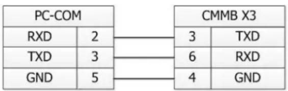
flowchart
graph LR
    A["PC-COM"] --> B["CMMB X3"]
    A --> C["RXD 2"]
    A --> D["TXD 3"]
    A --> E["GND 5"]
    B --> F["3 TXD"]
    B --> G["6 RXD"]
    B --> H["4 GND"]
Figure 10-1: Communication wiring between PC (DSub 9-pin) and CMMB controller
10.1.2 Multi-point connection
The communication protocol provides network operation with a host computer operating as a master and several CMMB controllers working as communication slaves (RS232_Loop_Enable(d5.15) must be set to 1, save and reboot the controller after setting). In that case the RS232 cabling must have a loop structure as follows:
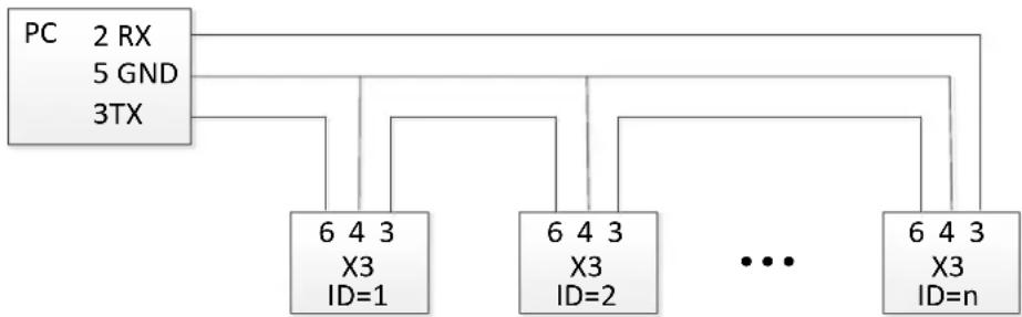
flowchart
graph TD
    PC["PC 2 RX\n5 GND\n3TX"] --> PC1["6 4 3\nX3\nID=1"]
    PC --> PC2["6 4 3\nX3\nID=2"]
    PC --> PCn["6 4 3\nX3\nID=n"]
    PC2 -.-> PCn
Figure 10-2: Communication wiring between PC (DSub 9-pin) and multiple CMMB controllers
10.2 Transport protocol
RS232 communication of the CMMB motor controller strictly follows master / slave protocol. The host computer send data to the CMMB controller. The controller checks the data regarding a checksum and the correct ID number, processes the data and returns an answer. Default communication settings for the CMMB motor controller are as follows:
Baud rate = 38,400 bps
Data bits = 8
Stop bits = 1
No parity check
The baud rate can be changed in RS232 BaudRate(d5.02). After changing the value it's necessary to save the setting and reboot the system.
The controller's ID can be changed in Node ID(d5.01).
The transport protocol uses a telegram with a fixed length of 10 bytes.
ID: The ID number of the slave
CHKS: Telegram checksum, CHKS = -SUM(byte 0 .... byte 8)
10.2.1 Point to point protocol
One host communicates with one controller, RS232_Loop_Enable(d5.15)=0)
The host sends:
The slave sends / The host receives
If the slave finds it's own ID in the host telegram, it checks the CHKS value. If the checksum does not match the slave would not generate an answer and the host telegram would be discarded.
10.2.2 Multi-point protocol
One host communicates with several controllers, RS232_Loop_Enable(d5.15)=1
The host sends:
The slave sends / The host receives (RS232_Loop_Enable(d5.15)=1):
If the host sends a telegram with an unused ID data will pass the RS232 loop but no slave answer will return.
The slave which finds it's own ID in the host telegram checks the CHKS value. If the checksum does not match the slave would not generate an answer and the host telegram would be discarded by that slave.
10.3 Data protocol
The data content of the transport protocol is the data protocol. It contains 8 bytes. The definition of the CMMB motor controller's RS232 data protocol is compatible with the CANopen SDO protocol, as well as the internal data organisation complies to the CANopen standard. All parameters, values and functions are accessible via a 24-bit address, built of a 16-bit index and 8-bit sub-index.
10.3.1 Download (from host to slave)
Download means that the host sends a command to write values to the objects in the slave, the slave generates an error message if when the value is downloaded to a non-existent object.
The host sends:
CMD: Specifies the direction of data transfer and the size of data.
23 (hex) Sends 4-byte data (bytes 4...7 contain 32 bits)
2b (hex) Sends 2-byte data (bytes 4 and 5 contain 16 bits)
2f (hex) Sends 1-byte data (bytes 4 contains 8 bits)
INDEX: Index in the object dictionary where data should be sent
SUB INDEX: Sub-index in object dictionary where data should be sent
DATA: 8, 16 or 32 bit value
The slave answers:
RES: Displays slave response:
60(hex) Data successfully sent
80(hex) Error, bytes 4...7 contain error cause
INDEX: 16-bit value, copy of index in host telegram
SUBINDEX: 8-bit value, copy of sub index in host telegram
RESERVED: Not used
10.3.2 Upload (from slave to host)
Upload means the master sends a command to read the object value from the slave. The slave generates an error if a non-existent object is requested.
The master sends:
CMD: Specifies the direction of data transfer
40(hex) always
INDEX: 16-bit value, index in the object dictionary where requested data reside.
SUBINDEX: 8-bit value, index, sub index in the object dictionary where requested data reside.
RESERVED: Bytes 4...7 not used
The slave answers:
RES: Displays slave response:
43(hex) bytes 4...7 contain 32-bit data
4B(hex) bytes 4 and 5 contain 16-bit data
4F(hex) byte 4 contains 8-bit data
80(hex) error, bytes 4 ... 7 contain error cause
INDEX: 16-bit value, copy of index in host telegram
SUBINDEX: 8-bit value, copy of subindex in host telegram
DATA: Data or error cause, depending on RES
10.4 RS232 telegram example
Following table shows the RS232 telegram example.
Table 10-1: RS232 telegram example
| ID | R/W | Index | Sub index | Data | Checksum | Meaning |
| 01 | 2B | 40 60 | 00 | 2F 00 00 00 | 05 | Set Controlword = 0x2F, enable the controller |
| 01 | 2F | 60 60 | 00 | 06 00 00 00 | 0A | Set Operation_Mode = 0x06 |
| 01 | 23 | 7A 60 | 00 | 50 C3 00 00 | EF | Set Tearget_position = 50000 |
| 01 | 40 | 41 60 | 00 | 00 00 00 00 | 1E | Read the Statusword |
Chapter 11 Appendix
11.1 Multi-Turn Encoders supported by CMMB
The CMMB can support the matched EMMB motors with Single/Multi-Turn Encoder.
The Single-Turn Encoder can provide one revolution's absolute angle infomation and the Multi-Turn Encoder can additionally provide 65536 absolute revolutions.

Information
The Multi-Turn Encoder can only remember 65536 revolutions. If the 65536 rev. is exceeded, Example: 70000 revolutions moved and 4464 position is shown after next reboot. 70000 - 65536 = 4464
11.1.1 Hardware requirements
For the use of an EMMB motor with Multi-Turn Encoder you have to use the NEFM-REG6-K-0.5-B-REG6
adapter with a Battery box. The Battery will buffer the absolute Multi-Turn revolutions.
For more informations read the manual of the NEFM adapter.
11.1.2 Application scenarios
The Multi-Turn Encoder is typically used in the system which is not suitable to perform the homing action or if homing is too much time consuming and inefficient. In such case the control of the servo controller regarding positioning has to be done with (or in combination with) communication and/or Position Table. Pulse Train as command interface alone cannot command the drive to a designated absolute target position. For the CMMB the use of Multi-Turn Encoders requires the use of the PC software or other communication methods for configuration (no panel addresses for important values like Home_Offset or Pos_Shift).
11.1.3 Warning and Error
11.1.3.1 Warning
If the battery voltage is down to about 3.0V (typical value) the Multi-Turn Encoder generates a warning to remind the user to change the battery. CMMB LED display flashes with "0001" three times quickly every 10s. The warning will be cleared automatically when the battery voltage will become normal. Access to the object 0x2680.00 to get the battery warning information by communication.
To avoid the loss of encoder data the battery should be replaced while the Control power for logic is supplied to the controller.
11.1.3.2 Connection Error
Like for the Single-Turn Encoder also for a Multi-Turn Encoder the CMMB Controller generates the "Encoder not connected" error if the encoder connector is disconnected, the encoder cable is damaged or when communication is disturbed by noise. The CMMB LED display shows the error "000.2".
The error can be reset if the connection is correct and the disturbance eliminated.
11.1.3.3 Multi-Turn Error
If the battery voltage is lower than about 2.69V or the battery is disconnected, the Multi-Turn Encoder generates an internal error to remind the user that the absolute position is not credible. The CMMB LED display shows the error "000.4" and this error cannot be reset by the normal Error Reset. CMMB will try to clear such error automatically in the following 2 conditions:
- When an Multi-Turn Encoder connected with a new CMMB controller or a CMMB controller at which the object 0x6410.01 was set to 0x3030.
- When a CMMB controller is connected with an Multi-Turn Encoder now but was connected with a Single-Turn Encoder before.
Otherwise, to clear the error in the encoder internally first, the user must set the object 0x2690.00 to 1 by LED panel d3.51 or by communication (e.g. CMMB Configurator).
After that the CMMB controller error can be reset by the normal Error Reset.

Note
After Multi-Turn Error the absolute position value is not credible any more and must be set again (see Absolute position definition).
11.1.4 Absolute position definition
Systems with Multi-Turn Encoder motors need to define the value of the actual position on a certain mechanical position. The CMMB motor controller supports two ways for that:
- Via Homing, by following procedure:
- Chose the right home method and related homing parameters, refer to chapter 6.6
- The Home_Offset is the important value: the actual position will be set to (-Home_Offset) at the homing trigger point
- Configure the related digit IO pins for the Homing Mode
- Start the Homing
-
After the Homing is finished successfully, store the controller parameters
After successful Homing, the CMMB sets an internal parameter Pos_Shift (object 0x60FB.07): Pos_Shift = Pos_Abs (object 0x6004.00) + Home_Offset at the homing trigger point. -
Via writing to Pos_Shift directly while the CMMB operation is disabled: Pos_Shiftnew
= Pos_Actual - Pos_Actualnew +Pos_Shift and storing of the controller parameters.
- Description
- Danger
- Warning
- Caution
- Note
- Text designations:
- Contents
- Chapter 1 Safety and requirements for product use ....1
- Safety....1
- Requirements for product use....2
- Chapter 2 Introduction....3
- Chapter 3 Installation of the CMMB motor controller ....8
- Electrical installation 9
- Chapter 4 Controller setup with LED panel ....15
- Panel operation.... 15
- Chapter 5 CMMB configurator, user guide....29
- Chapter 6 Operation modes and control modes....45
- Chapter 7 Tuning of the servo system control....68
- Chapter 8 Alarms and troubleshooting....76
- Chapter 9 List of CMMB series motor controller parameters....78
- Chapter 10 Communication ....86
- Chapter 11 Appendix ......90
- Chapter 1 Safety and requirements for product use
- Safety
- Safety instructions for commissioning, repair and de-commissioning
- Danger of electric shock
- Danger from unexpected movement of the motor or axis
- Protection against electric shock through protective extra-low voltage (PELV)
- Intended use
- Requirements for product use
- Transport and storage conditions
- Technical requirements
- Qualification of the specialists (requirements for personnel)
- Range of application and certifications
- Chapter 2 Introduction
- Product overview
- CMMB Motor controller
- EMMB Servo motor
- NEBM cables
- Device view
- Chapter 3 Installation of the CMMB motor controller
- Mechanical installation
- Environment requirements
- Mounting conditions
- Electrical installation
- Front view of CMMB series motor controller
- Power connector (X2)
- RS232 port (X3)
- Multi-function connector (X4)
- Encoder input (X5)
- Wiring of the CMMB servo system
- Selection of fuses, braking resistors and circuit breakers
- Chapter 4 Controller setup with LED panel
- Panel operation
- Panel menu structure and navigation
- Easy Use function
- Setup process with Easy Use function
- Flowchart and description of the EASY menu
- Information
- Flowchart and description of the tunE menu
- Jog mode (F006)
- Error History (F007)
- Chapter 5 CMMB configurator, user guide
- Getting started
- Language
- Opening and saving project files
- Starting communication
- Node ID and baud rate
- Objects (add, delete, help)
- Init save reboot
- Firmware update
- Read/write controller configuration
- Read settings from controller
- Write settings to controller
- Digital IO functions
- Digital inputs
- Digital outputs
- Gear ratio switch (expert only)
- Example:
- Gain switch (expert only)
- Fast Capture
- Scope
- Error display and error history
- Chapter 6 Operation modes and control modes
- General steps for starting a control mode
- Step 1: Wiring
- Step 2: IO function configuration
- Switch\_On\_Auto (expert only)
- Step 3: Set necessary parameters
- Step 4: Save and reboot
- Step 5: Start operation
- Velocity mode (-3, 3)
- Analog speed mode
- DIN speed mode
- Torque mode (4)
- Analog torque mode
- Final Result:
- Position mode (1)
- Position Table mode
- CTL Reg: Contains following bits:
- Pulse Train mode (-4)
- Master-slave mode
- Homing mode (6)
- Home\_N\_Blind:
- Chapter 7
- Tuning of the servo system control
- Auto-tuning
- Parameters for auto-tuning
- Start of auto-tuning
- Problems with auto-tuning
- Adjustment after auto-tuning.
- Manual tuning
- Tuning of the velocity loop
- Velocity feedback filter adjustment
- Output filter adjustment
- Velocity loop bandwidth calculation
- Integral gain adjustment
- Adjust Kvi\_sum\_limit
- Tuning of the position loop
- Position loop proportional gain adjustment
- Position loop velocity feedforward adjustment
- Position loop acceleration feedforward
- Smoothing filter
- Notch filter
- Factors which influence tuning results
- Chapter 8 Alarms and troubleshooting
- Chapter 9 List of CMMB series motor controller parameters
- F001
- F002
- F003
- F004
- F005
- Chapter 10 Communication
- RS232 wiring
- Point to point connection
- Multi-point connection
- Transport protocol
- Point to point protocol
- Multi-point protocol
- Data protocol
- Download (from host to slave)
- Upload (from slave to host)
- RS232 telegram example
- Chapter 11 Appendix
- Multi-Turn Encoders supported by CMMB
- Hardware requirements
- Application scenarios
- Warning and Error
- Warning
- Connection Error
- Multi-Turn Error
- Absolute position definition
Brand : Festo
Model : CMMB-AS-02
Category : Regulator