
DPA-40-D - Pressure pump Festo - Free user manual and instructions
Find the device manual for free DPA-40-D Festo in PDF.


| Type | Pneumatic Actuator |
| Series | DPA |
| Bore Diameter | 40 mm |
| Stroke Length | Up to 500 mm (configurable) |
| Operating Pressure | 1 to 10 bar |
| Operating Temperature | -10°C to 60°C |
| Action | Double-acting |
| Cushioning | Adjustable pneumatic cushioning |
| Position Sensing | For proximity switches (slot) |
| Mounting Type | Via accessories (foot, flange, clevis) |
| Piston Rod End | Internal thread M10 |
| Materials | Aluminum barrel, stainless steel piston rod |
| Wear Rings | PTFE composite |
| Seals | NBR |
| Conforms to Standards | ISO 15552 |
| Protection Class | IP40 |
| Media | Compressed air, filtered and lubricated |
| Maintenance | Replace seals if leaking |
| Repair Parts | Available as service kits |
| Weight (approx.) | 0.5 kg for 100 mm stroke |
Frequently Asked Questions - DPA-40-D Festo
User questions about DPA-40-D Festo
0 question about this device. Answer the ones you know or ask your own.
Ask a new question about this device
Download the instructions for your Pressure pump in PDF format for free! Find your manual DPA-40-D - Festo and take your electronic device back in hand. On this page are published all the documents necessary for the use of your device. DPA-40-D by Festo.
USER MANUAL DPA-40-D Festo
natural_image
Close-up of a metallic mechanical component with mounting holes and a black adjustment knob (no visible text or symbols)FESTO
(en) Operating instructions
Translation of the original instructions
Symbols: Installation and commissioning may only be per-

Warning
formed in accordance with these instructions by technicians with appropriate qualifications.

Caution

Note
Environment

Accessories
English 3.
Pressure booster DPA
Documentation on the product

For all available product documentation → www.festo.com/pk
1 Operating elements and ports
DPA-40 DPA-63/100

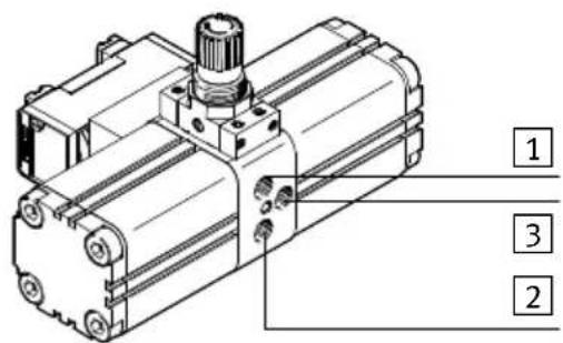
1 Pneumatic connection 1 for input pressure
2 Pneumatic connection 2 for output pressure
3 Pneumatic connection 3 for exhaust air
4 Rotary knob for output pressure (not DPA-...-D)

5 Manual override
6 Exhaust hole; sealed with sintered filter
7 Valve exhaust port (on the right and left of the valve sub-base); DPA-40 with silencers in scope of delivery
8 Threaded holes for fastening
Fig. 1
2 Function and application
The type DPA pressure booster has been designed for increasing the pressure in air supply lines. Due to its two coupled pressure chambers, the DPA functions as a double piston compressor. No external energy other than compressed air is required to operate the DPA. Once the input pressure has been applied, the DPA starts up automatically. An integrated way valve conducts the pressure, which is applied constantly at pneumatic connection 1, alternately into one compression chamber then into the other. These generate an output pressure of up to double the value of the input pressure. On pressure boosters with a controller, the pressure increase can be reduced by setting the rotary knob. When the set output pressure is reached, the DPA stops operating to save energy but restarts automatically if the pressure drops due to application operation.
With the DPA-...-A it is possible to record the individual strokes of the drive piston using an external sensor and an adding counter.

Note
Pressure boosters are intended to occasionally relieve compressed air. Pressure boosters are not suitable for use as compressor replacements, as wear on seals and drive pistons increases significantly during continuous operation without breaks.
3 Conditions of use

Note
Incorrect handling can result in malfunctioning.
- Make sure that the following specifications are always observed:
- Compare the maximum values specified in these operating instructions with your actual application (e.g. operating media, pressures, forces, temperatures, masses, flow rates).
- Ensure that there is a supply of correctly prepared compressed air.
•Take into consideration the ambient conditions at the location of use. - Please comply with national and local safety laws and regulations (e.g. Safety regulations as per EN 1012, part 1).
- Use a three-way on-off valve on the input side of the DPA.
- Use a three-way on-off valve on the output side of the DPA. In this way, the downstream switched system can be exhausted quickly.
- Remove the packing with the exception of the self-adhesive labels on the compressed air connections (to prevent dirt from entering).
It is intended that the packaging be recycled on the basis of its constituent materials (exception: oiled paper = other waste). - Please observe the warnings and instructions
- on the product and
- in these operating instructions.
- Use the product in its original state. Unauthorised modification is not permitted.
4 Transport and storage

Warning
Falling loads may cause personal injuries.
•Take the weight of the DPA into consideration. Depending on the version, the DPA can weigh up to 13 kg. The rotary knob must not be used as a support for transporting the DPA because the large load may dislodge the rotary knob.
5 Installation
Mechanical

Note
The DPA must not be installed on the controller thread because the controller thread may be destroyed under the load of the DPA.
Fasten the DPA in one of the following ways only:
| Type | Fastening method1) | Fastening | |
| DPA-40 | Direct fastening | – with 4 screws (M4) in the threaded holes of the DPA. Tightening torque 2 Nm. |  |
| With FDPA-40 flange mounting accessory | – Flange with 4 screws (M4) in the threaded holes of the DPA. Tightening torque 2 Nm.– Fit the flange to the wall with 2 screws (M5). | 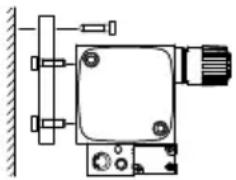 | |
| DPA-63/100 | Direct fastening – With | 4 screws (M10) in the threaded holes of the DPA. Tightening torque 30 Nm. | 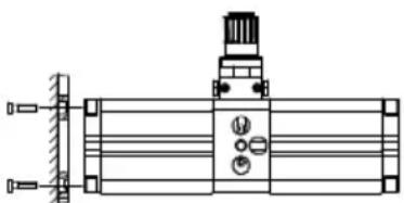 |
| With HUA foot mounting accessory (2x) | – Foot mounting, with two screws each in the threaded holes of the DPA on the right and left. Tightening torque 30 Nm. |  | |
| 1) The exhaust hole and both valve exhaust ports (6/7 → Fig. 1) must not be sealed. | |||
Fitting the proximity sensors for sensing option (DPA-...-A only) → Fig. 2
- Fasten the proximity sensor ^1 in one of the 6 available sensor grooves on the right-hand side of the DPA (rotary knob top, pneumatic ports front). The proximity sensor must be positioned in the middle of the cylinder barrel.
- Connect the proximity sensors to the adding counter.

natural_image
Technical line drawing of a mechanical assembly with no visible text or symbolsFig. 2

Note
The proximity sensor records each individual stroke of the drive piston. In order to arrive at the usual count of double strokes, the number of individual strokes has to be halved.
Information of the proximity sensor and the adding counter can be found in the operating instructions for these products.
Pneumatic connection for input pressure, output pressure, exhaust air

Note
Incorrectly dimensioned cable cross-sections can impair the timing behaviour of downstream switched components.
- Use hoses with a minimum inner diameter or the hose types recommended in Fig. 3 for the input and output pressure.
- Use a silencer for the exhaust air. If the exhaust air is to be ducted, it must be vented relative to atmosphere.
The exhaust air from both valve exhaust ports (7) → Fig. 1) must not be ducted.
- Check whether an air reservoir is required. In this way you will avoid pressure fluctuations.
- Connect the tubing to the supply ports as per Fig. 3.
With an output pressure greater than 10 bar, make sure that the permitted limits for the connecting elements used at output ② are observed (if necessary connect the tubing to the DPA).
DPA-40 DPA-63/100


natural_image
Technical line drawing of a mechanical component with mounting holes and a cylindrical shaft (no text or symbols)Fig. 3
| Type DPA-40 DPA-63 DPA-100 | ||||
| Connection number | 1 | Pneumatic connection 1 for input pressure | ||
| 2 Pneumatic connection 2 for output pressure | ||||
| 3 Pneumatic connection 3 for exhaust air | ||||
| Pneumatic connection | 1/2 | G^1/_4 | G^3/_8 | G^1/_2 |
| 3 M7 G^3/_8 G ^1/_2 | ||||
| Tightening torque | 1/2 | 15 Nm | 25 Nm | 40 Nm |
| 3 | 2 Nm | 25 Nm | 40 Nm | |
| Inner hose diameter/recommended hose type | 17 mm/ | PAN-10x1.5 | 12 mm/PAN-16x2 | 12 mm/PAN-16x2 |
| 25 mm/ | PAN-R-8x1.25 | 10 mm/PAN-R-16x3 | 10 mm/PAN-R-16x3 | |
Pneumatic connection for pressure gauges → Fig. 4
-
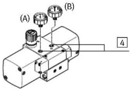
Remove the screws plugs from the pressure gauge ports 4.
-
DPA-40 only:
Seal off the pressure gauges with PTFE tape.
The pressure gauges for the DPA-63/100 have a PTFE coating. It is not necessary to seal them with PTFE tape.
- Firmly screw the pressure gauges into the ports 4 clockwise by hand. Pressure gauge (A) shows the input pressure, pressure gauge (B) shows the output pressure.
Use pressure gauges with a sufficient dial to show the input and output pressure ( 10 Technical data). To show the output pressure, a pressure gauge with a larger final value on the dial is required.
Exception: The DPA-...-10-MA-SET pressure gauge set ( 8 Accessories) contains two identical pressure gauges with a sufficient dial for the DPA-...-10.
DPA-40-10/16/D DPA-63/100-10/16

DPA-63-D DPA-100-D
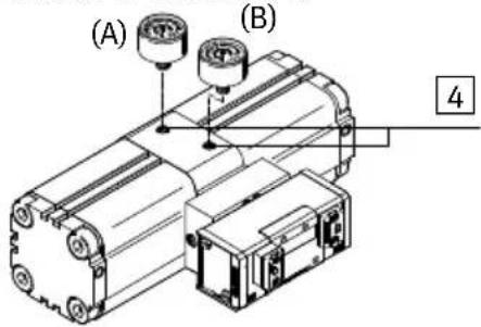
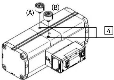
Fig. 4
- Align the pressure gauge with the spanner by screwing it in further by a maximum of 1.5 turns.
6 Commissioning

Warning
Sudden expulsion of compressed air can cause injuries.
- Make sure that the compressed air outputs of the DPA for output air 2 and exhaust air 3 are connected ( Fig. 3).

Note
High compressed air forces can damage equipment further along the compressed air path.
- Make sure that equipment connected downstream of the DPA is designed to withstand the maximum output pressure which can be achieved.

Note
The three-way on-off valve on the input side of the DPA must not be opened until the pressure in the system has been built up.
First open the three-way valve on the input side, then the three-way on-off valve on the output side.

Note
The output pressure on pressure boosters without a controller is twice the input pressure.
Consider the following correlations:
| Setting | Reaction |
| The set output pressure is lower than the input pressure | The pressure controller on the DPA vents until the pressures are equal |
| The input pressure is always 2 bar lower than the set output pressure | The DPA reaches the set output pressure |
| Increase the output pressure Increase of air consumption | |
| Air volume/current on the input side is too low | Output pressure fluctuates |
| Maximum controller settingDPA-...-10: typ. 10 bar, max. 14 barDPA-...-16: typ. 16 bar, max. 22 bar | The max. output pressure can be exceeded by up to 40 %(product-dependent scatter of the regulator springs) |
Setting the output pressure:

Note
Pressure gauges are strongly recommended for checking pressure levels.
- DPA-63/100-10 only:
Pull the rotary knob away from the housing.
-
Turn the adjusting knob (4) → Fig. 1) clockwise as far as it will go (status as at delivery).
-
Apply the input pressure to pneumatic port 1 on the DPA.
-
Turn the rotary knob (4) Fig. 1) clockwise until the desired output pressure is shown on the pressure gauge.
The pressure statuses are monitored by pressure gauges ( Fig. 4):
- Pressure gauge (A): input pressure
- Pressure gauge (B): output pressure
- DPA-63/100-10 only:
Press the rotary knob towards the housing to lock it.
7 Removal
- Switch off the compressed air. The system must be fully depressurised.
- First close the on-off valve on the output side of the DPA, then the on-off valve on the input side of the DPA.
- Then turn the rotary knob anti-clockwise as far as it will go.
- Disconnect the pneumatic ports of the DPA.
8 Accessories
| Designation for Type | ||
| Flange mounting DPA-40 FDPA-40 | ||
| Foot mounting DPA-63 HUA-63 | ||
| Pressure gauge set DPA-40-10 DPA-40-10-MA-SET | ||
| Pressure gauges | DPA-63-D/DPA-100-D | MA-40-16 18 -EN for input pressure, MA-40-25 18 -EN for output pressure |
9 Troubleshooting
| Malfunction Possible cause Remedial action | ||
| Output pressure fluctuates too much | Air consumption of downstream equipment too high | Use air reservoir |
| The desired output pressure is not reached | - Input pressure too low- Too many consuming devices at the Output | Increase the input pressure |
| Flow too low Silencer | , tubing or screw connectors with insufficient flow used | Use only components of sufficient sizes |
| Insufficient air volume at compressed air input | Increase volume at compressed air input (e. g. with large compressed air reservoir) | |
| Pressure booster does not start | Fault in commissioning/unfavourable Operating conditions (valve in mid-position) | Briefly exhaust the switching valve by pressing the manual override 5 (→ Fig. 1) |
10 Technical data
| Type DPA-40 DPA-63 | DPA-100 | ||||||||
| -10 -1 | 6 -D -1 | 10 -16 | - D -10 | -16 -D | |||||
| Input pressure [bar] 2.5 | ...8 | 2.5 ...10 | 2.5 ...8 | 2 ...8 | 2 ...10 | 2 ...8 | 2 ...8 | 2 ...10 | 2 ...8 |
| Output [bar] 4 pressure^1) | 5 ...10 | 4.5 ...16 | 5 ...16 | 4 ...10 | 4 ...16 | 4 ...16 | 4 ...10 | 4 ...16 | 4 ...16 |
| Operating medium Filtered compressed air, non-lubricated, grade of filtration40 μm | |||||||||
| Installation position as desired | |||||||||
| Ambient [°C] +5temperature | ... +60 | ||||||||
| Weight [kg] 1.5 6.0 13.0 | |||||||||
| 1) If the regulator spring is at maximum tension (rotary knob turned all the way clockwise), the maximum output pressure can be exceeded by 40 %:– Max. 14 bar on DPA-...-10– Max. 22 bar on DPA-...-16 | |||||||||
DPA
Copyright:
Festo SE & Co. KG
Ruiter Straße 82
73734 Esslingen
Germany
Phone:
+49 711 347-0
Fax:
+49 711 347-2144
Reproduction, distribution or sale of this document or communication of its contents to others without express authorization is prohibited. Offenders will be liable for damages. All rights reserved in the event that a patent, utility model or design patent is registered.
E-mail:
service_international@festo.com
Internet:
www.festo.com
- FESTO
- Translation of the original instructions
- Pressure booster DPA
- Documentation on the product
- Operating elements and ports
- Function and application
- Note
- Conditions of use
- Transport and storage
- Warning
- Installation
- Mechanical
- Pneumatic connection for pressure gauges → Fig. 4
- Commissioning
- Setting the output pressure:
- Removal
- Accessories
- Troubleshooting
- Technical data
Brand : Festo
Model : DPA-40-D
Category : Pressure pump