P.BE-CMMP-CO-SW-DE - Speed controller Festo - Free user manual and instructions
Find the device manual for free P.BE-CMMP-CO-SW-DE Festo in PDF.


| Product Type | User Manual (PDF) |
| Brand | Festo |
| Model | P.BE-CMMP-CO-SW-DE |
| Language | English |
| Pages | 210 |
| File Format | |
| Revision Index | 0708NH |
| Date of Revision | 24.04.2008 |
| Target Device Series | CMMP Motor Controllers |
| Communication Protocol | CANopen (DS301, DSP402) |
| Key Topics | Activation, Cabling, SDO/PDO, NMT, Operating Modes |
| Safety Instructions | Included (electrical drives) |
| Parameter Management | Load/Save, Default/Application sets |
| Operating Modes | Homing, Profile Position, Velocity, Torque, Interpolated |
| Error Handling | EMCY messages, error codes table |
| Object Directory | Full index with descriptions |
| Diagrams | Cabling, state machine, access sequence |
| Intended Audience | Experienced users of CMMP series |
Frequently Asked Questions - P.BE-CMMP-CO-SW-DE Festo
User questions about P.BE-CMMP-CO-SW-DE Festo
0 question about this device. Answer the ones you know or ask your own.
Ask a new question about this device
Download the instructions for your Speed controller in PDF format for free! Find your manual P.BE-CMMP-CO-SW-DE - Festo and take your electronic device back in hand. On this page are published all the documents necessary for the use of your device. P.BE-CMMP-CO-SW-DE by Festo.
USER MANUAL P.BE-CMMP-CO-SW-DE Festo
CANopen for Motor Controller CMMP...
FESTO
Manual
CANopen
CMMP...

natural_image
Front view of a FESTO industrial control unit with visible ports, connectors, and ventilation slots (no readable text or symbols beyond branding)Manual
557 344
de 0708NH
[723 757]
Edition ____ ____ en 0708NH
Description ____ ____ P.BE-CMMP-CO-SW-EN
Order no. ____ ____ 557 344
© (Festo SE & Co. KG, D-73726 Esslingen, 2008)
Internet: http://www.festo.com
Mail: service_international@festo.com
The copying, distribution and utilization of this document as well as the communication of its contents to others without expressed authorization is prohibited. Offenders will be held liable for the payment of damages. All rights reserved, in particular the right to carry out patent, utility model or ornamental design registrations.
Index of Revisions
| Preparer: | Festo SE & Co. KG | |||
| Manual name: | CANopen for Motor controller CMMP | |||
| File name: | ||||
| File location: | ||||
| Serial No. | Manual | Revision index | Date of change | |
| 001 | Creation | 0708NH | 24.04.2008 | |
Trade names
Microsoft and Windows are either registered trademarks or trademarks of Microsoft Corporation in the United States and/or other countries.
C
Contents
1. General information....9
1.1 Documentation....9
1.2 CANopen 10
2. Safety instructions for electrical drives and controllers 11
2.1 General Information 11
2.2 Hazards due to Incorrect Use.... 12
2.3 Safety instructions 13
2.3.1 General safety information 13
2.3.2 Safety Instructions for Installation and Maintenance....15
2.3.3 Protection against Contact with Electrical Parts.... 17
2.3.4 Protection against Electrical Shocks through Low-Voltage Protection (PELV) 19
2.3.5 Protection against Hazardous Movements 19
2.3.6 Protection against Contact with Hot Parts.... 20
2.3.7 Protection when Handling and Installing 20
3. Cabling and Plug Assignment....22
3.1 Pin Allocations....22
3.2 Cabling Note 23
4. Activation of CANopen....24
4.1 Overview 24
5. Access Procedure 25
5.1 Introduction.... 25
5.2 SDO Access 26
5.2.1 SDO Sequences for Reading and Writing 26
5.2.2 SDO Error Messages 28
5.2.3 Simulation of SDO Access via RS232 29
5.3 PDO Message 30
5.3.1 Description of the Objects 31
5.3.2 Objects for PDO Parameter Setting 34
5.3.3 Activation of PDOs 40
5.4 SYNC message....40
5.5 EMERGENCY Message 41
5.5.1 Overview....41
5.5.2 Structure of the EMERGENCY Message 42
5.5.3 Description of the Objects 45
5.6 Network Management (NMT Service) 47
C
C
5.7 Bootup 49
5.7.1 Overview....49
5.7.2 Structure of the Bootup Message 49
5.8 Heartbeat (error control protocol) 49
5.8.1 Overview....49
5.8.2 Structure of the Heartbeat Message 49
5.8.3 Description of the Objects 50
5.9 Nodeguarding (error control protocol) 50
5.9.1 Overview....50
5.9.2 Structure of the Nodeguarding messages.... 51
5.9.3 Description of the Objects 51
5.9.4 Objekt 100D h: life_time_factor....52
- Setting Parameters 54
6.1 Load and Save Parameter Sets....54
6.1.1 Overview....54
6.1.2 Description of the Objects 56
6.2 Compatibility settings....57
6.2.1 Overview....57
6.2.2 Description of the Objects 57
6.3 Conversion Factors (Factor Group) 59
6.3.1 Overview....59
6.3.2 Description of the Objects 60
6.4 Final stage parameters 68
6.4.1 Overview....68
6.4.2 Description of the Objects 69
6.5 Current Regulator and Motor Adjustment....76
6.5.1 Overview....76
6.5.2 Description of the Objects 77
6.6 Speed regulator....84
6.6.1 Overview....84
6.6.2 Description of the Objects 84
6.7 Position Controller (Position Control Function) 86
6.7.1 Overview....86
6.7.2 Description of the Objects 89
6.8 Nominal value limitation 98
6.8.1 Description of the Objects 98
6.9 Encoder adjustments.... 101
6.9.1 Overview.... 101
6.9.2 Description of the Objects 101
C
6.10 Incremental encoder emulation.... 106
6.10.1 Overview.... 106
6.10.2 Description of the Objects 106
6.11 Command/feedback value activation.... 107
6.11.1 Overview.... 107
6.11.2 Description of the Objects 108
6.12 Analogue inputs 111
6.12.1 Overview.... 111
6.12.2 Description of the Objects 111
6.13 Digital inputs and outputs 113
6.13.1 Overview.... 113
6.13.2 Description of the Objects 113
6.14 Limit switch/homing switch.... 117
6.14.1 Overview.... 117
6.14.2 Description of the Objects 117
6.15 Sampling of positions.... 119
6.15.1 Overview.... 119
6.15.2 Description of the Objects 120
6.16 Brake triggering.... 123
6.16.1 Overview.... 123
6.16.2 Description of the Objects 123
6.17 Device Information 124
6.17.1 Description of the Objects 124
6.18 Error management.... 131
6.18.1 Overview.... 131
6.18.2 Description of the Objects 131
- Device control 134
7.1 Condition diagram (state machine) 134
7.1.1 Overview.... 134
7.1.2 The Condition Diagram of the Motor Controller (State Machine) ..... 135
7.1.3 Controlword (control word).... 139
7.1.4 Read-Out of the Motor Controller Condition 142
7.1.5 Statuswords (status words) 143
7.1.6 Description of the other objects.... 151
C
C
8. Operating modes 154
8.1 Setting the operating mode.... 154
8.1.1 Overview.... 154
8.1.2 Description of the Objects 154
8.2 Operating Mode Reference Travel (Homing Mode)....156
8.2.1 Overview.... 156
8.2.2 Description of the Objects 157
8.2.3 Reference Travel Processes 162
8.2.4 Control of Reference Travel.... 167
8.3 Positioning Operating Mode (Profile Position Mode).... 168
8.3.1 Overview.... 168
8.3.2 Description of the Objects 169
8.3.3 Functional description 172
8.4 Interpolated position mode 174
8.4.1 Overview.... 174
8.4.2 Description of the Objects 175
8.4.3 Functional description 182
8.5 RPM Regulation Operating Mode (Profile Velocity Mode)....184
8.5.1 Overview.... 184
8.5.2 Description of the Objects 186
8.6 Velocity ramps....192
8.7 Torque Regulation Operating Mode (Profile Torque Mode) 195
8.7.1 Overview.... 195
8.7.2 Description of the Objects 196
9. Index 201
1. General information
1. General information
1.1 Documentation
This manual describes how the motor controller of the CMMP series can be integrated into a CANopen network environment. It describes setting of the physical parameters, activation of CANopen protocol, integration into the CAN network and communication with the motor controller. It is directed at people who are already familiar with this motor controller series.
It contains safety instructions that must be observed.
You will find additional information in the following manuals for the CMMP product family:
- Start-up "CMMP motor controller":
Description of the device function and software functions of the firmware, including RS232 communication. Description of the parameterisation software with instructions for the initial start-up of a motor controller of the CMMP series.
- Description "CMMP motor controller":
Description of the technical data and device function as well as information on the installation and operation of the CMMP motor controller.
About the Version
The hardware version indicates the version status of the mechanical equipment and electronics. The firmware version indicates the version status of the operating system.
You can find the specifications on the version status as follows:
- Hardware version and firmware version in the parameterisation software for active device connection under "Device data".
| Firmware | Hardware | Parameterisation software | Comment |
| V1.0 | |||
1. General information
1.2 CANopen
CANopen is a standard worked out by the "CAN in Automation" association. A number of device manufacturers are organised in this association. This standard has largely replaced the current manufacturer-specific CAN protocols. As a result, the end user has a manufacturer-independent communication interface.
The following manuals, among others, can be obtained from this association:
CiA Draft Standard 201 ... 207
These documents cover the general principles and embedding of CANopen into the OSI layered architecture. The relevant points of this book are presented in this CANopen manual, so procurement of DS201 ... 207 is generally not necessary.
CiA Draft Standard 301
This book describes the fundamental design of the object directory of a CANopen device and access to it. The statements of DS201 ... 207 are also made concrete. The elements of the object directory needed for the CMMP motor controller families and the related access methods are described in this manual. Procurement of DS301 is recommended but not absolutely necessary.
CiA Draft Standard 402
This book covers concrete implementation of CANopen in drive regulators. Although all implemented objects are also briefly documented and described in this CANopen manual, the user should have this book available.
Source of supply:
CAN in Automation (CiA) International Headquarters
The CANopen implementation of the motor controller is based on the following standards:
[1] - ] CiA Draft Standard 301, Version 4.02, 13. February 2002
[2] - ] CiA Draft Standard Proposal 402, Version 2.0, 26. July 2002
- Safety instructions for electrical drives and controllers
2. Safety instructions for electrical drives and controllers
2.1 General Information
Festo SE & Co.KG accepts no liability for damage due to failure to observe the warnings in these operating instructions.

Please note
Before start-up, read Safety instructions for electrical drives and controllers starting with page 11.
If the documentation in this language cannot be understood correctly, please ask and inform the supplier.
Correct and safe operation of the motor controller requires appropriate and correct transportation, storage, mounting and installation as well as careful operation and maintenance.

Please note
Only trained and qualified personnel may work with electrical equipment:
Trained and Qualified Personnel
as defined by this product manual or the warnings on the product itself are people who are sufficiently familiar with the set-up, mounting, start-up and operation of the product as well as with all warnings and protective measures in accordance with these operating instructions and have the qualifications corresponding to their work:
- Training and instruction or authorisation to switch devices/system on and off, earth and properly mark them in accordance with the standards of safety technology.
- Training or instruction in accordance with the standards of safety technology in the maintenance and use of suitable safety equipment.
- Training in first aid.
The following remarks must be read before the system is placed in operation for the first time to avoid bodily injury or property damage:

Always comply with these safety instructions.
2. Safety instructions for electrical drives and controllers

Do not try to install the motor controller or place it into operation before you have carefully read all safety instructions for electrical drives and controls in this document.
These safety instructions and all other user instructions must be read before each work with the motor controller.

If no user instructions are available for the motor controller, please contact your sales representative.
- Demand the immediate sending of these documents to the person or persons responsible for safe operation of the motor controller.

If the motor controller is sold, rented or lent or passed on to a third party in any other way, these safety instructions must also be passed on.

The operator is not permitted to open the motor controller for safety and guarantee reasons.

The requirement for proper functioning of the motor controller is correct project planning!

Warning
DANGER!
Incorrect handling of the motor controller and failure to observe the warnings specified here as well as improper tampering with the safety equipment may result in property damage, bodily injury, electric shock or, in extreme cases, death.
2.2 Hazards due to Incorrect Use

Warning
DANGER!
High electrical voltage and high load current!
Danger of death or severe bodily injury from electric shock!
2. Safety instructions for electrical drives and controllers

Warning
DANGER!
High electrical voltage due to incorrect connection!
Danger of death or bodily injury from electric shock!

Warning
DANGER!
Device housing surfaces may be hot!
Danger of injury! Danger of burns!

Warning
DANGER!
Dangerous movements!
Danger of death, severe bodily injury or property damage from unintended movements of the motors!
2.3 Safety instructions
2.3.1 General safety information

Warning
The motor controller corresponds to protective class IP20 and contamination class 1.
- Care must be taken that the environment corresponds to this protection and contamination class.

Warning
Use only accessories and replacement parts permitted by the manufacturer.

Warning
In accordance with EN standards and VDE regulations, the motor controllers must be connected in such a way that they can be disconnected from the mains network with suitable isolation means (e.g. main switch, fuse, circuit breaker).
2. Safety instructions for electrical drives and controllers

The motor controller can be protected with an AC/DC-sensitive RCD circuit breaker (RCD = Residual Current protective Device) of 300 mA.

Warning
For switching the control contacts, gold contacts or contacts with high contact pressure should be used.

As a precautionary measure, fault-elimination measures for switching systems must be taken, such as wiring fuses and relays with RC filters or diodes.

Observe the safety regulations and stipulations of the country in which the device is used.

Warning
The environmental conditions specified in the product documentation must be complied with.
Safety-critical applications are not permitted unless expressly approved by the manufacturer.

The instructions for an EMC-suitable installation should be taken from the product manual of the CMMP family.
Compliance with the limit values required by the national regulations is the responsibility of the manufacturer of the system or machine.

Warning
The technical data, connection and installation requirements for the motor controller must be taken from this product manual and must absolutely be complied with.

Warning
DANGER!
The general construction and safety regulations for work on high-voltage power installations (e.g. DIN, VDE, EN, IEC or other national and international regulations) must be observed.
Failure to do so can result in death, bodily injury or significant property damage.

The following precautionary measures also apply without claim to completeness:
- VDE 0100 Stipulation for construction of power installations of up to 1000 volts
- EN 60204 Electrical equipment of machines
- EN 50178 Equipping high-voltage systems with electronic operating media
2.3.2 Safety Instructions for Installation and Maintenance
For installation and maintenance of the system, the relevant DIN, VDE, EN and IEC regulations as well as all governmental and local safety and accident protection regulations apply. The system builder or operator must ensure compliance with these regulations:

Warning
Operation, maintenance and/or repair of the motor controller may only be performed by personnel trained and qualified for the work or for work with electrical devices.
Avoidance of accidents, bodily injury and/or property damage:

Warning
The standard-delivery motor brake or an external motor brake controlled by the drive control device is not adequate by itself for personal protection!
- Additionally secure vertical axes against falling or dropping after the motor is switched off, such as by:
- mechanical locking of the vertical axis,
- external brake/catch/clamping device or
- adequate counterbalancing of the axis.
2. Safety instructions for electrical drives and controllers

Warning
During operation and up to about 5 minutes after the motor controller is switched off, the external or internal braking resistance can create dangerous intermediate circuit voltage, which can cause death or severe bodily injury on contact.
- Before performing maintenance work, make sure that the power supply is switched off, interlocked and the intermediate circuit discharged.
- Switch off power to the electrical equipment via the main switch and secure it against being switched back on. Wait until the intermediate circuit is discharged for:
- maintenance work and repair
- cleaning
- long interruptions in operation.

Warning
Care must be taken during installation. During both installation and later operation of the drive, make sure that no shavings, metal dust or installation parts (screws, nuts, sections of pipe) fall into the motor controller.

Also make sure that the external power supply of the control section (24 V) is switched off.

Power to the power section must always be switched off before switching off the 24 V power supply to the control section.

Warning
Perform work in the machine area Tonly with the AC or DC power supply switched off and locked out.
Switched-off final stages or controller enable are not appropriate lockouts. In case of malfunction, this can result in unintended running of the drive.

Warning
- Perform start-up with the motor running at idle to avoid mechanical damage, such as through incorrect direction of rotation.
2. Safety instructions for electrical drives and controllers

Warning
Electronic devices are not fail-safe.
- The user is responsible for returning the system to a safe condition if the electrical device fails.

Warning
DANGER!
The motor controller and, in particular, the brake resistance, external or internal, can take on high temperatures, which can cause severe bodily burns on contact.
2.3.3 Protection against Contact with Electrical Parts
This section refers only to devices and drive components with voltages above 50 volts. Parts with voltages above 50 volts can be hazardous to people and result in electric shock if touched. When electrical devices are operated, certain parts of these devices are by necessity under hazardous voltage.

Warning
Potentially fatal voltage!
High electrical voltage!
Danger of death or severe bodily injury from electric shock!
For installation and maintenance of the system, the relevant DIN, VDE, EN and IEC regulations as well as all governmental and local safety and accident protection regulations apply. The system builder or operator must ensure compliance with these regulations:

Warning
Before switching on devices, attach intended covers and protective equipment for protection against contact.
For installed devices, ensure protection against direct touching of electrical parts by means of a control cabinet, for example.
The VGB4 regulations must be followed!

Warning
Always firmly connect the earthed conductor of the electrical equipment and devices to the mains power supply.
Due to the integrated net filter, leakage current is greater than 3.5 mA!
2. Safety instructions for electrical drives and controllers

Warning
In accordance with standard EN 60617, pay attention to the minimum copper diameter for the protective conductor connection in its entire length!

Warning
Prior to start-up, also for short-time measurement and testing purposes, always connect the protective conductor to all electrical devices in accordance with the connection plan or with the earthing conductor.
Otherwise, high voltages may occur on the housing, which can cause electric shock.

Warning
Do not touch the components' electrical connection points in the switched-on state.

Warning
- Before access to electrical parts with voltages greater than 50 volts, separate the device from the mains network or the voltage source.
- Secure to prevent switching back on.

Warning
During installation, pay attention to the level of intermediate circuit voltage especially with regard to insulation and protective measures.
Ensure proper earthing, conductor dimensioning and appropriate protection against short circuiting.

Warning
The device has an intermediate fast discharge circuit in accordance with EN 60204 section 6.2.4. In certain device constellations, particularly where several motor controllers are switched parallel in the intermediate circuit or with a non-connected braking resistance, the fast discharge may not have any effect. The motor controllers can remain under dangerous voltage for up to 5 minutes after they are switched off (residual condensor charge).
2.3.4 Protection against Electrical Shocks through Low-Voltage Protection (PELV)
All connections and terminals with voltages from 5 to 50 volts on the motor controller are of the low-voltage protection type, which are designed to be shock-proof in accordance with the following standards:
- International: IEC 60364-4-41
- European countries in the EU: EN 50178/1998, section 5.2.8.1

Warning
DANGER!
High electrical voltage due to incorrect connection!
Danger of death or injury from electric shock!
Only devices, electrical components and lines with low-voltage protection (PELV = Protective Extra Low Voltage) can be connected to any connections and terminals with voltages from 0 to 50 volts.
Connect only voltages and circuits with safe separation from dangerous voltages.
Safe separation is achieved through isolating transformers, secure optocouplers or mains-free battery operation.
2.3.5 Protection against Hazardous Movements
Hazardous movements can also be caused by faulty triggering of connected motors. The causes can be of the most varied of kinds:
- dirty or defective wiring or cabling
- errors in operating components
- faults in the measurement and signal transmitters
- defects or components that are not EMC-suitable
- faults in the software in the higher-level control system.
These malfunctions can occur immediately after switch-on or after an indefinite time in operation.
Monitoring in the drive components exclude malfunctions in the connected drives as much as possible. But this alone cannot be relied on when protection of people and especially the danger of bodily injury and/or property damage are considered. Until the installed monitoring takes effect, a defective drive movement must definitely be expected, the amount of which depends on the type of control and the operating state.

Warning
DANGER!
Dangerous movements!
Danger of death or injury, severe bodily injury or property damage!
For the above reasons, personal protection must be ensured through monitoring or higher-level system measures. These are planned according to the specific circumstances of the system by the system builder based on a hazard and error analysis. These hereby include the safety regulations applicable for the system. Through switching off or bypassing of safety equipment or due to its failure to activate, unpredictable movements of the machine or other malfunctions may occur.
2.3.6 Protection against Contact with Hot Parts

Warning
DANGER!
Device housing surfaces may be hot!
Danger of injury! Danger of burns!

Warning
Danger of burns!
- Do not touch housing surfaces in the proximity of heat sources!
- Before touching them, let devices cool off 10 minutes after being switched off.
Touching hot parts of the equipment, such as device housings containing heatsinks and resistances, can result in burns!
2.3.7 Protection when Handling and Installing
Handling and installation of specific parts and components in an inappropriate way can result in burns.

Warning
DANGER!
Danger of injury from incorrect handling!
Bodily injury due to squeezing, shearing, cutting, hitting!
2. Safety instructions for electrical drives and controllers
For this, the general safety notes apply:

Warning
- Observe the general set-up and safety regulations on handling and installation.
- Use appropriate installation and transport equipment.
- Take appropriate precautions to prevent being caught and pinched.
- Use only appropriate tools. If required, use special tools.
- Use lifting devices and tools properly.
- If required, use appropriate protective equipment (such as safety goggles, safety shoes, protective gloves).
- Do not stand under suspended loads.
-
Immediately clean leaked fluids on the floor due to slipping hazards.
-
Cabling and Plug Assignment
3. Cabling and Plug Assignment
3.1 Pin Allocations
For the CMMP family of devices, the CAN interface is already integrated into the motor controller and thus is always available.
The CAN bus connection is designed as a 9-pole D-SUB plug (on the controller side) in accordance with standards.

Fig. 3.1: CAN plug connector for CMMP

Caution
CAN bus cabling
When cabling the motor controller via the CAN bus, you should always comply with the following information and remarks to obtain a stable, malfunction-free system. If cabling is improperly done, malfunctions can occur on the CAN bus during operation. These can cause the motor controller to shut off with an error for safety reasons.

120 Ω end resistor
No end resistor is integrated into the devices of the CMMP series.
3. Cabling and Plug Assignment
3.2 Cabling Note
The CAN bus offers a simple and fail-safe possibility to link all components of a system with each other. But the prerequisite for this is that all subsequent cabling instructions are observed.

flowchart
graph LR
    A["120Ω"] --> B["CAN-SHIELD"]
    B --> C["CAN-GND"]
    C --> D["CAN-L"]
    D --> E["CAN-H"]
    E --> F["CAN-SHIELD"]
    F --> G["CAN-GND"]
    G --> H["CAN-L"]
    H --> I["CAN-H"]
    I --> J["CAN-SHIELD"]
    J --> K["CAN-GND"]
    K --> L["CAN-L"]
    L --> M["CAN-H"]
    M --> N["120Ω"]
Fig. 3.2: Cabling example
- The individual nodes of the network are connected point-to-point to each other, so the CAN cable is looped from controller to controller (see Fig. 3.2).
- At both ends of the CAN cable, there must be an end resistor of exactly 120 ± 5 % . Frequently, such an end resistor is already built into CAN cards or a PLC and must be taken into account accordingly.
- For cabling, a shielded cable with exactly two twisted lead pairs must be used. A twisted lead pair is used to connect CAN-H and CAN-L. The cores of the other pair are used together for CAN-GND. The screen of the cable is guided onto the CAN Shield connections for all nodes
A table with the technical data of usable cables is located at the end of this chapter.
- Use of adapter plugs is not recommended for CAN bus cabling. But if this is still necessary, make sure that metallic plug housings are used to connect the cable shield.
- To keep disturbance as low as possible, motor cable should not be laid parallel to signal lines, motor cable designed in accordance with the specification, motor cable properly shielded and earthed.
- For additional information on the design of a disturbance-free CAN bus cabling, we refer you to the Controller Area Network protocol specification, version 2.0, from Robert Bosch GmbH, 1991.
- Technical data, CAN bus cable:
2 pairs of 2 twisted leads, d ≥0.22 mm ^2
Loop resistance < 0.2 Φm
Screened
Impedance 100 ... 120 Ω
- Activation of CANopen
4. Activation of CANopen
4.1 Overview
The CAN interface with the CANopen protocol is activated one time via the serial interface of the motor controller. The CAN protocol is activated via the CAN bus window of the parameterisation software.

A total of 3 different parameters must be set:
- Baud rate
This parameter determines the baud rate in Kbaud used on the CAN bus. Note that high baud rates require a low maximum cable length.
- Node number
A node number, which may occur only once in the network, must be assigned to each participant for unambiguous identification. The device is addressed via this node number.
- Protocols
The following profiles for communication via the CAN bus are available for selection:
- CANopen protocol in accordance with DS301 with application profile DSP402 or
- the positioning profile from Festo FHPP.
Note that the named parameters can only be changed if the protocol is deactivated.

Note that the parameter setting of the CANopen function remains intact after a reset if the parameter set of the motor controller was saved.
5. Access Procedure
5.1 Introduction
CANopen provides a simple and standardised possibility to access the parameters of the motor controller (e.g. the maximum motor current). To achieve this, a unique number (index and subindex) is assigned to each parameter (CAN object). The totality of all adjustable parameters is designated an object directory.
Essentially two methods are available for accessing CAN objects via the CAN bus: A confirmed access type, in which the motor controller acknowledges each parameter access (via so-called SDOs), and an unconfirmed access type, in which no acknowledgement is made (via so-called PDOs).

flowchart
graph LR
    A["Control unit"] -->|Access form control unit| B["CMMP"]
    B -->|SDO\nAcknowledge from motor controller| A

flowchart
graph LR
    A["Control unit"] -->|PDO (Transmit-PDO) Confirmation from motor controller| B["CMMP"]

flowchart
graph LR
    A["Control unit"] -->|PDO (Receive- PDO) Process data from control unit| B["CMMP"]
Fig. 5.1: Access Procedure
As a rule, the motor controller is parameterised and also controlled via SDO access. In addition, other types of messages (so-called communication objects), which are sent either by the motor controller or the higher-level controller, are defined for special application cases:
SDO Service Data Object Are used for normal parameter setting of the motor controller.
PDO Process Data Object Fast exchange of process data (e.g. actual speed) possible.
SYNC Synchronisation message Synchronisation of multiple CAN nodes
EMCY Emergency message Transmission of error messages.
NMT Network Management Network service: All CAN nodes can be worked on simultaneously, for example.
HEARTBEAT Error Control Protocol Monitoring of the communications participants through regular messages.
Every message sent on the CAN bus contains a type of address which is used to determine the bus participant for which the message is meant. This number is designated the identifier.
5. Access Procedure
The lower the identifier, the greater the priority of the message. Identifiers are established for the above-named communication objects. The following sketch shows the basic design of a CANopen message:

5.2 SDO Access
The Service Data Objects (SDO) permit access to the object directory of the motor controller. This access is especially simple and clear. It is therefore recommended to build up the application at first only with SDOs and only later to convert to the faster but also more complicated Process Data Objects (PDOs).
SDO access always starts from the higher-level controller (Host). This either sends the motor controller a write command to modify a parameter in the object directory or a read command to read out a parameter. For each command, the host receives an answer that either contains the read-out value or, in the case of a write command, serves as an acknowledgement.
For the motor controller to recognise that the command is meant for it, the host must send the command with a specific identifier. This consists of the base 600_h + node number of the motor controller involved. The motor controller answers accordingly with the identifier 580_h + node number.
The design of the commands or answers depends on the data type of the object to be read or written, since either 1, 2 or 4 data bytes must be sent or received. The following data types are supported:
| UINT8 | 8 bit value without algebraic sign | 0 | ... | 255 |
| INT8 | 8 bit value with algebraic sign | -128 | ... | 127 |
| UINT16 | 16 bit value without algebraic sign | 0 | ... | 65535 |
| INT16 | 16 bit value with algebraic sign | -32768 | ... | 32767 |
| UINT32 | 32 bit value without algebraic sign | 0 | ... | (2^32 - 1) |
| INT32 | 32 bit value with algebraic sign | -(2^31) | ... | (2^31 - 1) |
5.2.1 SDO Sequences for Reading and Writing
To read out or describe objects of these number types, the following listed sequences are used. The commands for writing a value into the motor controller begin with a different identifier, depending on the data type. The answer identifier, in contrast, is always the same. Read commands always start with the same identifier, and the motor controller answers differently, depending on the data type returned. All numbers are kept in hexadecimal form.
5. Access Procedure
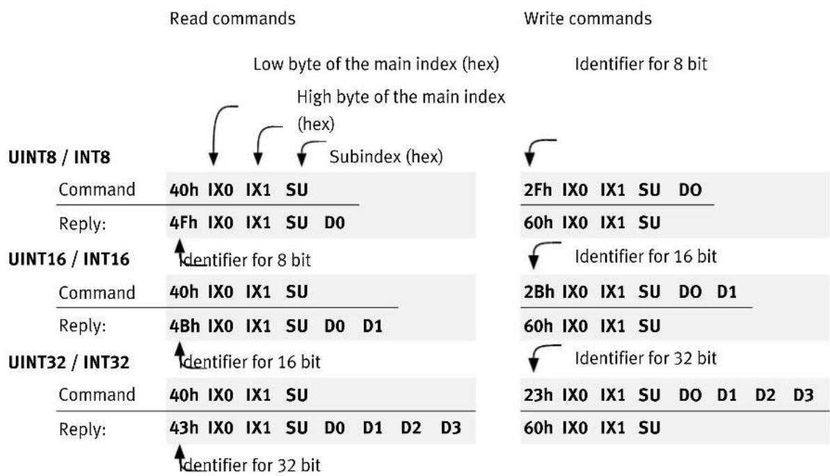
flowchart
graph TD
    A["Read commands"] --> B["Low byte of the main index (hex)"]
    A --> C["High byte of the main index (hex)"]
    A --> D["Subindex (hex)"]
    E["Write commands"] --> F["Identifier for 8 bit"]
    G["Command"] --> H["40h IX0 IX1 SU"]
    I["Reply:"] --> J["4Fh IX0 IX1 SU DO"]
    K["UINT16 / INT16"] --> L["Identifier for 8 bit"]
    M["Command"] --> N["40h IX0 IX1 SU"]
    O["Reply:"] --> P["4Bh IX0 IX1 SU DO D1"]
    Q["UINT32 / INT32"] --> R["Identifier for 16 bit"]
    S["Command"] --> T["40h IX0 IX1 SU"]
    U["Reply:"] --> V["43h IX0 IX1 SU DO D1 D2 D3"]
    W["2Fh IX0 IX1 SU DO"] --> X["60h IX0 IX1 SU"]
    Y["Identifier for 16 bit"] --> Z["2Bh IX0 IX1 SU DO D1"]
    AA["60h IX0 IX1 SU"] --> AB["60h IX0 IX1 SU"]
    AC["Identifier for 32 bit"] --> AD["23h IX0 IX1 SU DO D1 D2 D3"]
    AE["60h IX0 IX1 SU"] --> AF["60h IX0 IX1 SU"]
EXAMPLE
| UINT8 / INT8 | Reading obj. 6061_00hReturn data: 01h | Writing obj. 1401_02hData: EFh |
| Command | 40h 61h 60h 00h | 2Fh 01h 14h 02h EFh |
| Reply: | 4Fh 61h 60h 00h 01h | 60h 01h 14h 02h |
| UINT16 / INT16 | Reading obj. 6041_00hReturn data: 1234h | Writing obj. 6040_00hData: 03E8h |
| Command | 40h 41h 60h 00h | 2Bh 40h 60h 00h E8h 03h |
| Reply: | 4Bh 41h 60h 00h 34h 12h | 60h 40h 60h 00h |
| UINT32 / INT32 | Reading obj. 6093_01hReturn data: 12345678h | Writing obj. 6093_01hData: 12345678h |
| Command | 40h 93h 60h 01h | 23h 93h 60h 01h 78h 56h 34h 12h |
| Reply: | 43h 93h 60h 01h 78h 56h 34h 12h | 60h 93h 60h 01h |

Caution
The acknowledgement from the motor controller must always be waited for!
Only when the motor controller has acknowledged the request may additional requests be sent.
5. Access Procedure
5.2.2 SDO Error Messages
In case of an error when reading or writing (for example, because the written value is too large), the motor controller answers with an error message instead of the acknowledgement:

| Error codeF3 F2 F1 F0 | Meaning |
| 05 03 00 00h | Protocol error: Toggle bit was not changed |
| 05 04 00 01h | Protocol error: Client / server command specifier invalid or unknown |
| 06 06 00 00h | Access faulty due to a hardware problem *1) |
| 06 01 00 00h | Access type is not supported . |
| 06 01 00 01h | Read access to an object that can only be written |
| 06 01 00 02h | Write access to an object that can only be read |
| 06 02 00 00h | The addressed object does not exist in the object directory |
| 06 04 00 41h | The object must not be entered in a PDO (e.g. ro object in RPDO) |
| 06 04 00 42h | The length of the objects entered in the PDO exceeds the PDO length |
| 06 04 00 43h | General parameter error |
| 06 04 00 47h | Overflow of an internal variable / general error |
| 06 07 00 10h | Protocol error: Length of the service parameter does not agree |
| 06 07 00 12h | Protocol error: Length of the service parameter is too large |
| 06 07 00 13h | Protocol error: Length of the service parameter is too small |
| 06 09 00 11h | The addressed subindex does not exist |
| 06 09 00 30h | The data exceed the range of values of the object |
| 06 09 00 31h | The data are too large for the object |
| 06 09 00 32h | The data are too small for the object |
| 06 09 00 36h | Upper limit is less than lower limit |
| 08 00 00 20h | Data cannot be transmitted or stored *1) |
| 08 00 00 21h | Data cannot be transmitted or stored, since the regulator is working locally |
| 08 00 00 22h | Data cannot be transmitted or stored, since the regulator is not in the correct state for this *3) |
| 08 00 00 23h | There is no object dictionary available *2) |
^1) Returned in accord. with DS301 in case of incorrect access to store_parameters / restore_parameters.
^2) This error is returned, for example, when another bus system controls the motor controller or the parameter access is not permitted.
^*3) "Condition" here should be understood in general: It may be a problem of the incorrect operating mode, or a technology module that is not available or the like.
5. Access Procedure
5.2.3 Simulation of SDO Access via RS232
The firmware of the motor controller offers the possibility to simulate SDO access via the RS232 interface. In this way, after being written, objects in the test phase can be read and checked via the CAN bus over the RS232 interface. Application creation is facilitated through use of the CI terminal of the parameterisation software.
The syntax of the commands is:
| Read commands | Write commands | ||
| UINT8 / INT8 | Main index (hex) Subindex (hex) | ||
| Command | ? XXXX SU | = XXXX SU: WW | |
| Reply: | = XXXX SU: WW | = XXXX SU: WW | |
| UINT16 / INT16 | 8 bit data (hex) | ||
| Command | ? XXXX SU | = XXXX SU: WWWW | |
| Reply: | = XXXX SU: WWWW | = XXXX SU: WWWW | |
| UINT32 / INT32 | 16 bit data (hex) | ||
| Command | ? XXXX SU | = XXXX SU: WWWWWWW | |
| Reply: | = XXXX SU: WWWWWWW | = XXXX SU: WWWWWWW | |
| 32 bit data (hex) | |||
Note that the commands are entered as characters without any blanks.
| Read error | Write error | ||
| Command: | ?XXXX SU | =XXXX SU: WWWWWWWWW1) | |
| Reply: | ! FFFFFFF | ! FFFFFFF | |
| 32 bit error code F3F2F1F0 in accordance with chapter 5.2.2 | 32 bit error code F3 F2 F1 F0 in accordance with chapter 5.2.2 |
1) For errors, the reply is structured in the same way for all 3 write commands (8, 16, 32 bit).
The commands are entered as characters without spaces.

Caution
Never use these test commands in applications!
Access via RS232 only serves test purposes and is not suitable for real-time-capable communication.
In addition, the syntax of the test commands can be changed at any time.
5.3 PDO Message
With Process Data Objects (PDOs), data can be transmitted in an event-driven manner. The PDO thereby transmits one or more previously established parameters. Other than with an SDO, there is no acknowledgement when a PDO is transmitted. After PDO activation, all recipients must therefore be able to process any arriving PDOs at any time. This normally means a significant software effort in the host computer. This disadvantage is offset by the advantage that the host computer does not need to cyclically query parameters transmitted by a PDO, which leads to a strong reduction in CAN bus capacity utilisation.
EXAMPLE
The host computer would like to know when the motor controller has completed a positioning from A to B.
When SDOs are used, it must constantly, such as every millisecond, query the statusword object, with which it uses up the bus capacity.
When a PDO is used, the motor controller is parameterised at the start of the application in such a way that, with every change in the statusword object, a PDO containing the statusword object is deposited.
Instead of constantly querying, the host computer thus automatically receives a corresponding message as soon as the event occurs.
A distinction is made between the following types of PDOs:
| Transmit PDO (T-PDO) | Controller | Motor controller sends PDO when a certain event occurs |
| Receive PDO | Host | Motor controller evaluates PDO when a certain event occurs |
The motor controller has four transmit and four receive PDOs.
In the PDOs, almost all objects of the object directory can be entered (mapped). This means, the PDO contains the actual speed, position value, etc. as data. The motor controller must first be informed of the data to be transmitted, since the PDO only contains reference data and no information about the type of parameter. In the example below, the actual position is transmitted in the data bytes 0 ... 3 of the PDO and the actual speed in the bytes 4 ... 7.
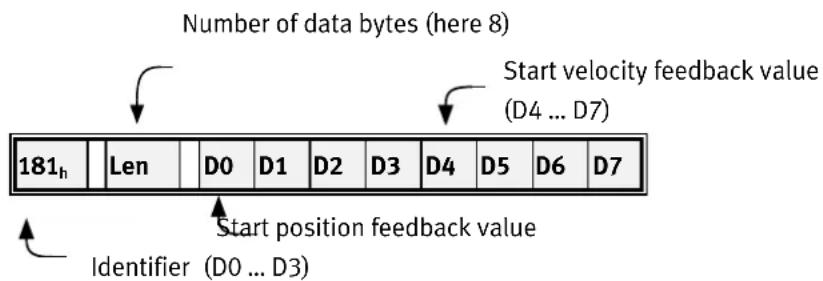
In this way, almost any desired data telegrams can be defined. The following chapters describe the settings necessary for this.
5.3.1 Description of the Objects
Identifier of the PDO COB_ID_used_by_PDO
In the object COB_ID_used_by_PDO, the identifier in which the respective PDO is sent or received is entered. If bit 31 is set, the respective PDO is deactivated. This is the default setting for all PDOs.
The COB-ID may only be changed if the PDO is deactivated, that is, bit 31 is set. A different identifier than the one currently set in the regulator may therefore only be written if bit 31 is simultaneously set.
The set bit 30 shows when the identifier is read that the object cannot be queried by a remote frame. This bit is ignored during writing and is always set during reading.
Number of objects to be transmitted
number_of_mapped_objects
This object specifies how many objects should be mapped into the corresponding PDO. The following limitations must be observed:
A maximum of 4 objects can be mapped per PDO.
A PDO may have a maximum of 64 bits (8 bytes).
Objects to be transmitted
first_mapped_object ... fourth_mapped_object
For each object contained in the PDO, the motor controller must be told the corresponding index, subindex and length. The stated length must agree with the stated length in the object dictionary. Parts of an object cannot be mapped.
The mapping information has the following format:

To simplify the mapping, the following procedure is established:
- The number of mapped objects is set to 0.
- The parameters first_mapped_object ... fourth_mapped_object may be written (the overall length of all objects is not relevant at this time).
- The number of mapped objects is set to a value between 1 ... 4. The length of all these objects must now not exceed 64 bits.
Transmission type
transmission\_type and inhibit\_time
Which event results in sending (transmit PDO) or evaluation (receive PDO) of a message can be determined for each PDO:
| Value | Meaning | Permitted with |
| 01_h ... FO_h | SYNC-MessageThe numerical value specifies how many SYNC messages must be received before the PDO- is sent (T-PDO) or- evaluated (R-PDO) | TPDOsRPDOs |
| FE_h | CyclicalThe transfer PDO is cyclically updated and sent by the motor controller. The time period is set by the object inhibit_time.Receive PDOs, in contrast, are evaluated immediately after reception. | TPDOs(RPDOs) |
| FF_h | ChangeThe transfer PDO is sent when at least 1 bit has changed in the data of the PDO.With inhibit_time, the minimum interval between sending two PDOs can also be established in 100 μs steps. | TPDOs |
The use of all other values is not permitted.
Masking
transmit\_mask\_high and transmit\_mask\_low
If "change" is selected as the transmission_type, the TPDO is always sent when at least 1 bit of the TPDO changes. But frequently it is necessary that the TPDO should only be sent when certain bits have changed. Therefore, the TPDO can be equipped with a mask: Only the bits of the TPDO that are set to "1" in the mask are used to evaluate whether the PDO has changed. Since this function is manufacturer-specific, all bits of the masks are set as default value.
EXAMPLE
The following objects should be transmitted in one PDO:
| Name of the object | Index_Subindex | Meaning |
| statusword | 6041_h\_00h | Controller regulation |
| modes_of_operation_display | 6061_h\_00h | Operation mode |
| digital_inputs | 60FD_h\_00h | Digital inputs |
The first transmit PDO (TPDO 1) should be used, which should always be sent whenever one of the digital inputs changes, but at a maximum of every 10 ms. As identifier for this PDO, 187h should be used.
1.) Deactivating PDO
If the PDO is active, it must first be deactivated.
Writing the identifier with bit 31 set (PDO is deactivated): cob_id_used_by_pdo = C0000187 _h
2.) Deleting number of objects
Set the number of objects to zero in order to be able to change the object mapping. number_of_mapped_objects = 0
3.) Setting parameters for objects that are to be mapped
The above-listed objects must be combined into a 32 bit value:
Index =6041h Subin. = Length = first_mapped_object =
00h 10h
Index =6061h Subin. = Length = second_mapped_object =
00h 08h
Index =60FDh Subin. = Length = third_mapped_object =
00h 20h
4.) Setting parameters for number of objects
The PDO should contain 3 objects number_of_mapped_objects =
5.) Parameterising transmission type
The PDO should be sent when changes (to the digital inputs) are sent. transmission_type = To ensure that only changes to the digital inputs result in transmission, the PDO is masked so that only the 16 bits of the object 60FD_n "come through". The PDO should be sent no more than every 10~ms (100× 100~ s) . inhibit_time =
6.) Setting identifier parameters
The PDO should be sent with identifier 187h.
Write the new identifier and
activate the PDO by deleting bit 31:⇒ cob_id_used_by_pdo = 40000187h

Note that parameter setting of the PDOs may generally only be changed when the network status (NMT) is not operational. See also chapter 5.3.3.
5.3.2 Objects for PDO Parameter Setting
The motor controllers of the CMMP series contain a total of 4 transmit and 4 receive PDOs. The individual objects for setting parameters for these PDOs are the same for all TPDOs and all RPDOs in each case. For that reason, only the parameter description of the first TPDO is explicitly listed. The meaning can also be used for the other PDOs, which are listed in table form in the following:
| Index | 1800_h |
| Name | transmit_pdo_parameter_tpdo1 |
| Object code | RECORD |
| No. of Elements | 3 |
| Sub-index | 01_h |
| Description | cob_id_used_by_pdo_tpdo1 |
| Data Type | UINT32 |
| Access | rw |
| PDO Mapping | no |
| Units | -- |
| Value Range | 181_h ... 1FF_h , bit 30 and 31 may be set |
| Default Value | C0000181_h |
| Sub-index | 02_h |
| Description | transmission_type_tpdo1 |
| Data Type | UINT8 |
| Access | rw |
| PDO Mapping | no |
| Units | -- |
| Value Range | 0 ... 8C_h , FE_l , FF_h |
| Default Value | FF_h |
5. Access Procedure
| Sub-index | 03_h |
| Description | inhibit_time_tpdo1 |
| Data Type | UINT16 |
| Access | rw |
| PDO Mapping | no |
| Units | 100 μs (i.e. 10 = 1 ms) |
| Value Range | -- |
| Default Value | 0 |
| Index | 1A00_h |
| Name | transmit_pdo_mapping_tpdo1 |
| Object code | RECORD |
| No. of Elements | 4 |
| Sub-index | 00_h |
| Description | number_of_mapped_objects(tpdo1 |
| Data Type | UINT8 |
| Access | rw |
| PDO Mapping | no |
| Units | -- |
| Value Range | 0 ... 4 |
| Default Value | see table |
| Sub-index | 01_h |
| Description | first_mapped_object_tpdo1 |
| Data Type | UINT32 |
| Access | rw |
| PDO Mapping | no |
| Units | -- |
| Value Range | -- |
| Default Value | see table |
5. Access Procedure
| Sub-index | 02_h |
| Description | second_mapped_object_tpdo1 |
| Data Type | UINT32 |
| Access | rw |
| PDO Mapping | no |
| Units | -- |
| Value Range | -- |
| Default Value | see table |
| Sub-index | 03_h |
| Description | third_mapped_object(tpdo1) |
| Data Type | UINT32 |
| Access | rw |
| PDO Mapping | no |
| Units | -- |
| Value Range | -- |
| Default Value | see table |
| Sub-index | 04_h |
| Description | fourth_mapped_object_tpdo1 |
| Data Type | UINT32 |
| Access | rw |
| PDO Mapping | no |
| Units | -- |
| Value Range | -- |
| Default Value | see table |

Note that the object groups transmit_pdo_parameter_xxx and transmit_pdo_mapping_xxx can only be written when the PDO is deactivated (bit 31 set in cob_id_used_by_pdo_xxx).
5. Access Procedure
1st Transmit PDO
| Index | Comment | Type | Acc. | Default Value |
| 1800_h\_00_h | number of entries | UINT8 | ro | 03_h |
| 1800_h\_01_h | COB-ID used by PDO | UINT32 | rw | C0000181_h |
| 1800_h\_02_h | transmission type | UINT8 | rw | FF_h |
| 1800_h\_03_h | inhibit time (100 μs) | UINT16 | rw | 0000_h |
| 1A00_h\_00_h | number of mapped objects | UINT8 | rw | 01_h |
| 1A00_h\_01_h | first mapped object | UINT32 | rw | 60410010_h |
| 1A00_h\_02_h | second mapped object | UINT32 | rw | 00000000_h |
| 1A00_h\_03_h | third mapped object | UINT32 | rw | 00000000_h |
| 1A00_h\_04_h | fourth mapped object | UINT32 | rw | 00000000_h |
2nd Transmit PDO
| Index | Comment | Type | Acc. | Default Value |
| 1801_h\_00_h | number of entries | UINT8 | ro | 03_h |
| 1801_h\_01_h | COB-ID used by PDO | UINT32 | rw | C0000281_h |
| 1801_h\_02_h | transmission type | UINT8 | rw | FF_h |
| 1801_h\_03_h | inhibit time (100 μs) | UINT16 | rw | 0000_h |
| 1A01_h\_00_h | number of mapped objects | UINT8 | rw | 02_h |
| 1A01_h\_01_h | first mapped object | UINT32 | rw | 60410010_h |
| 1A01_h\_02_h | second mapped object | UINT32 | rw | 60610008_h |
| 1A01_h\_03_h | third mapped object | UINT32 | rw | 00000000_h |
| 1A01_h\_04_h | fourth mapped object | UINT32 | rw | 00000000_h |
3rd Transmit PDO
| Index | Comment | Type | Acc. | Default Value |
| 1802_h\_00_h | number of entries | UINT8 | ro | 03_h |
| 1802_h\_01_h | COB-ID used by PDO | UINT32 | rw | C0000381_h |
| 1802_h\_02_h | transmission type | UINT8 | rw | FF_h |
| 1802_h\_03_h | inhibit time (100 μs) | UINT16 | rw | 0000_h |
| 1A02_h\_00_h | number of mapped objects | UINT8 | rw | 02_h |
| 1A02_h\_01_h | first mapped object | UINT32 | rw | 60410010_h |
| 1A02_h\_02_h | second mapped object | UINT32 | rw | 60640020_h |
| 1A02_h\_03_h | third mapped object | UINT32 | rw | 00000000_h |
| 1A02_h\_04_h | fourth mapped object | UINT32 | rw | 00000000_h |
5. Access Procedure
4rd Transmit PDO
| Index | Comment | Type | Acc. | Default Value |
| 1803_h\_00_h | number of entries | UINT8 | ro | 03_h |
| 1803_h\_01_h | COB-ID used by PDO | UINT32 | rw | C0000481_h |
| 1803_h\_02_h | transmission type | UINT8 | rw | FF_h |
| 1803_h\_03_h | inhibit time (100 μs) | UINT16 | rw | 0000_h |
| 1A03_h\_00_h | number of mapped objects | UINT8 | rw | 02_h |
| 1A03_h\_01_h | first mapped object | UINT32 | rw | 60410010_h |
| 1A03_h\_02_h | second mapped object | UINT32 | rw | 606C0020_h |
| 1A03_h\_03_h | third mapped object | UINT32 | rw | 00000000_h |
| 1A03_h\_04_h | fourth mapped object | UINT32 | rw | 00000000_h |
tpdo_1_transmit_mask
| Index | Comment | Type | Acc. | Default Value |
| 2014_h\_00_h | number of entries | UINT8 | ro | 02_h |
| 2014_h\_01_h | tpdo_1_transmit_mask_low | UINT32 | rw | FFFFFFFF_h |
| 2014_h\_02_h | tpdo_1_transmit_mask_high | UINT32 | rw | FFFFFFFF_h |
tpdo_2_transmit_mask
| Index | Comment | Type | Acc. | Default Value |
| 2015_h\_00_h | number of entries | UINT8 | ro | 02_h |
| 2015_h\_01_h | tpdo_2_transmit_mask_low | UINT32 | rw | FFFFFFFF_h |
| 2015_h\_02_h | tpdo_2_transmit_mask_high | UINT32 | rw | FFFFFFFF_h |
tpdo_3_transmit_mask
| Index | Comment | Type | Acc. | Default Value |
| 2016_h\_00_h | number of entries | UINT8 | ro | 02_h |
| 2016_h\_01_h | tpdo_3_transmit_mask_low | UINT32 | rw | FFFFFFFF_h |
| 2016_h\_02_h | tpdo_3_transmit_mask_high | UINT32 | rw | FFFFFFFF_h |
tpdo_4_transmit_mask
| Index | Comment | Type | Acc. | Default Value |
| 2017_h\_00_h | number of entries | UINT8 | ro | 02_h |
| 2017_h\_01_h | tpdo_4_transmit_mask_low | UINT32 | rw | FFFFFFFF_h |
| 2017_h\_02_h | tpdo_4_transmit_mask_high | UINT32 | rw | FFFFFFFF_h |
5. Access Procedure
1st Receive PDO
| Index | Comment | Type | Acc. | Default Value |
| 1400_h\_00_h | number of entries | UINT8 | ro | 02_h |
| 1400_h\_01_h | COB-ID used by PDO | UINT32 | rw | C0000201_h |
| 1400_h\_02_h | transmission type | UINT8 | rw | FF_h |
| 1600_h\_00_h | number of mapped objects | UINT8 | rw | 01_h |
| 1600_h\_01_h | first mapped object | UINT32 | rw | 60400010_h |
| 1600_h\_02_h | second mapped object | UINT32 | rw | 00000000_h |
| 1600_h\_03_h | third mapped object | UINT32 | rw | 00000000_h |
| 1600_h\_04_h | fourth mapped object | UINT32 | rw | 00000000_h |
2nd Receive PDO
| Index | Comment | Type | Acc. | Default Value |
| 1401_h\_00_h | number of entries | UINT8 | ro | 02_h |
| 1401_h\_01_h | COB-ID used by PDO | UINT32 | rw | C0000301_h |
| 1401_h\_02_h | transmission type | UINT8 | rw | FF_h |
| 1601_h\_00_h | number of mapped objects | UINT8 | rw | 02_h |
| 1601_h\_01_h | first mapped object | UINT32 | rw | 60400010_h |
| 1601_h\_02_h | second mapped object | UINT32 | rw | 60600008_h |
| 1601_h\_03_h | third mapped object | UINT32 | rw | 00000000_h |
| 1601_h\_04_h | fourth mapped object | UINT32 | rw | 00000000_h |
3rd Receive PDO
| Index | Comment | Type | Acc. | Default Value |
| 1402_h\_00_h | number of entries | UINT8 | ro | 02_h |
| 1402_h\_01_h | COB-ID used by PDO | UINT32 | rw | C0000401_h |
| 1402_h\_02_h | transmission type | UINT8 | rw | FF_h |
| 1602_h\_00_h | number of mapped objects | UINT8 | rw | 02_h |
| 1602_h\_01_h | first mapped object | UINT32 | rw | 60400010_h |
| 1602_h\_02_h | second mapped object | UINT32 | rw | 607A0020_h |
| 1602_h\_03_h | third mapped object | UINT32 | rw | 00000000_h |
| 1602_h\_04_h | fourth mapped object | UINT32 | rw | 00000000_h |
5. Access Procedure
4rd Receive PDO
| Index | Comment | Type | Acc. | Default Value |
| 1403_h\_00_h | number of entries | UINT8 | ro | 02_h |
| 1403_h\_01_h | COB-ID used by PDO | UINT32 | rw | C0000501_h |
| 1403_h\_02_h | transmission type | UINT8 | rw | FF_h |
| 1603_h\_00_h | number of mapped objects | UINT8 | rw | 02_h |
| 1603_h\_01_h | first mapped object | UINT32 | rw | 60400010_h |
| 1603_h\_02_h | second mapped object | UINT32 | rw | 60FF0020_h |
| 1603_h\_03_h | third mapped object | UINT32 | rw | 00000000_h |
| 1603_h\_04_h | fourth mapped object | UINT32 | rw | 00000000_h |
5.3.3 Activation of PDOs
For the motor controller to send or recieve PDOs, the following points must be met:
- The object number_of_mapped_objects must not equal zero.
- In the object cob_id_used_for_pdos, bit 31 must be deleted.
- The communication status of the motor controller must be operational (see chapter 5.6, Network Management: NMT Service).
For parameters to be set for PDOs, the following points must be met:
- The communication status of the motor controller must not be operational.
5.4 SYNC message
Several devices of a system can be synchronised with each other. To do this, one of the devices (usually the higher-level controller) sends out synchronisation messages periodically. All connected controllers receive these messages and use them for handling the PDOs (see chapter 5.3).

The identifier, on which the motor controller receives the SYNC message, is set permanently to 080_h . The identifier can be read out via the object cob_id_sync.
| Index | 1005_h |
| Name | cob_id_sync |
| Object code | VAR |
| Data Type | UINT32 |
5. Access Procedure
| Access | rw |
| PDO Mapping | no |
| Units | -- |
| Value Range | 80000080_h, 00000080_h |
| Default Value | 00000080_h |
5.5 EMERGENCY Message
The motor controller monitors the function of its major assemblies. These include the power supply, final stage, angle transmitter evaluation and technology connections. In addition, the motor (temperature, angle transmitter) and limit switch are checked. Incorrect parameterisations can also result in error messages (division by zero, etc.). When an error occurs, the error number is shown in the motor controller's display. If several error messages occur simultaneously, the message with the highest priority (lowest number) is always shown in the display.
5.5.1 Overview
The motor controller transmits an EMERGENCY message when an error occurs or an error is acknowledged. The identifier of this message is put together from the identifier 80h und der node number of the affected controller.

flowchart
graph TD
    A["0"] --> B["Error free"]
    B --> C["1"]
    B --> D["4"]
    C --> E["Error occurred"]
    D --> E
    E --> F["2"]
    E --> G["3"]
    G --> H["End"]
After a reset, the regulator is in the Error Free state (which it might leave immediately, since an error has been present from the beginning). The following condition transitions are possible:
| No. | Cause | Meaning |
| 0 | Initialization completed | |
| 1 | Error occurs | There was no error, and an error occurs. An EMERGENCY telegram is sent with the error code of the error that occurred. |
| 2 | Error acknowledgement | An error acknowledgement (see chapter 7.1.5) is attempted, but not all causes are fixed. |
5. Access Procedure
| No. | Cause | Meaning |
| 3 | Error occurs | There is already an error, and another error occurs.An EMERGENCY telegram is sent with the error code of the new error. |
| 4 | Error acknowledgement | An error acknowledgement is attempted, and all causes are fixed.An EMERGENCY telegram is sent with the error code 0000. |
Tab. 5.1: Possible condition transitions
5.5.2 Structure of the EMERGENCY Message
When an error occurs, the motor controller transmits an EMERGENCY message. The identifier of this message is put together from the identifier 81_h and node number of the affected motor controller.
The EMERGENCY message consists of eight data bytes, whereby the first two bytes contain an error_code, which is listed in the following table. An additional error code is in the third byte (object 1001_h ). The remaining five bytes contain zeros.

The following error codes can occur:
| Error_code (hex) | Display | Meaning |
| 0000 | -- | Regulator is error-free |
| 6180 | E 01 0 | Stack Overflow |
| 3220 | E 02 0 | Low voltage intermediate circuit |
| 4310 | E 03 x | Excess temperature in motor |
| 4210 | E 04 0 | Excess temperature power section |
| 4280 | E 04 1 | Excess temperature intermediate circuit |
| 5114 | E 05 0 | Malfunction of internal voltage 1 |
| 5115 | E 05 1 | Malfunction of internal voltage 2 |
| 5116 | E 05 2 | Malfunction of drive supply |
| 5410 | E 05 3 | Undervoltage digital I/O |
| 5410 | E 05 4 | Excess current digital I/O |
| 2320 | E 06 x | Short circuit, final stage |
| 3210 | E 07 0 | Excess voltage |
| 7380 | E 08 0 | Angle transmitter error resolver |
| 7382 | E 08 2 | Error track signals Z0 incremental encoder |
| 7383 | E 08 3 | Error track signals Z1 incremental encoder |
| 7384 | E 08 4 | Error track signals of digital incremental encoder |
| 7385 | E 08 5 | Error track signals Hall generator signals incremental encoder |
| 7386 | E 08 6 | Communication error angle encoder |
| 7387 | E 08 7 | Signal amplitude incremental track faulty |
| 7388 | E 08 8 | Internal angle transmitter error |
| 7389 | E 08 9 | Angle encoder at X2b is not supported |
| 73A1 | E 09 0 | Type CMMP angle encoder parameter set |
| 73A2 | E 09 1 | Angle encoder parameter set cannot be decoded |
| 73A3 | E 09 2 | Angle encoder parameter set: Version unknown |
| 73A4 | E 09 3 | Angle encoder parameter set: Data structure defective |
| 73A5 | E 09 7 | EPROM angle encoder write-protected |
| 73A6 | E 09 9 | EEPROM angle encoder too small |
| 8A80 | E 11 0 | Homing run: Error at the start |
| 8A81 | E 11 1 | Error during homing run |
| 8A82 | E 11 2 | Homing run: Zero pulse error |
| 8A83 | E 11 3 | Homing run: timeout |
| 8A84 | E 11 4 | Homing run: Incorrect / invalid limit switch |
| 8A85 | E 11 5 | Homing run: P_t / following error |
| 8A86 | E 11 6 | Homing run: End of the search section |
| 8180 | E 12 0 | CAN bus: Double node number |
| 8120 | E 12 1 | CAN communication error: BUS OFF |
| 8181 | E 12 2 | Communication error CAN while sending |
| 8182 | E 12 3 | Communication error CAN while receiving |
| 6185 | E 15 0 | Division by 0 |
| 6186 | E 15 1 | Outside range (run over/under) |
| 6181 | E 16 0 | Program execution faulty |
| 6182 | E 16 1 | Illegal interrupt |
| 6187 | E 16 2 | Initialisation error |
| 6183 | E 16 3 | Unexpected state |
| 8611 | E 17 x | Limit value contour error exceeded |
| 5280 | E 21 1 | Error 1 ammeter U |
| 5281 | E 21 1 | Error 1 ammeter V |
| 5282 | E 21 2 | Error 2 ammeter U |
| 5283 | E 21 3 | Error 2 ammeter V |
| 6080 | E 25 0 | Invalid device type |
| 6081 | E 25 1 | Device type not supported |
| 6082 | E 25 2 | HW revision not supported |
| 6083 | E 25 3 | Device function limited |
| 5580 | E 26 0 | Missing user-parameter set |
| 5581 | E 26 1 | Check sum error |
| 5582 | E 26 2 | Flash: Error when writing |
| 5583 | E 26 3 | Flash: Error when deleting |
| 5584 | E 26 4 | Flash: Error in the internal flash |
| 5585 | E 26 5 | Missing calibration data |
| 5586 | E 26 6 | Missing user-position data records |
| 8611 | E 27 0 | Warning threshold following error |
| FF01 | E 28 0 | Operating hours counter missing |
| FF02 | E 28 1 | Operating hours counter: Write error |
| FF03 | E 28 2 | Operating hours counter corrected |
| FF04 | E 28 3 | Operating hours counter converted |
| 6380 | E 30 0 | Internal conversion error |
| 2312 | E 31 0 | I^2t – motor |
| 2311 | E 31 1 | I^2t – motor controller |
| 2313 | E 31 2 | I^2t – PFC |
| 2314 | E 31 3 | I^2t – brake resistance |
| 3280 | E 32 0 | Intermediate circuit charge time exceeded |
| 3281 | E 32 1 | Undervoltage for active PFC |
| 3282 | E 32 5 | Overload brake chopper |
| 3283 | E 32 6 | Intermediate circuit discharge time exceeded |
| 3284 | E 32 7 | Power supply missing for controller enable |
| 3285 | E 32 8 | Power supply broke down during controller enable |
| 3286 | E 32 9 | Phase failure |
| 8A87 | E 33 0 | Encoder emulation following error |
| 8780 | E 34 0 | Synchronisation error (resynchronisation) |
| 8781 | E 34 1 | Synchronisation error (synchronisation broke down) |
| 8480 | E 35 0 | Linear motor turn-through protection |
| 6320 | E 36 x | Parameter was limited |
| 8612 | E 40 x | SW limit switch reached |
| 8680 | E 42 0 | Positioning: Drive stops due to missing connection positioning |
| 8681 | E 42 1 | Positioning: Drive stops because rotation direction reversal not permitted |
| 8682 | E 42 2 | Positioning: Prohibited rotational direction reversal after HALT |
| 8081 | E 43 0 | Limit switches: Negative command value blocked |
| 8082 | E 43 1 | Limit switches: Positive command value blocked |
| 8083 | E 43 2 | Limit switches: Positioning suppressed |
| 8084 | E 45 0 | Driver supply cannot be switched off |
| 8085 | E 45 1 | Driver supply cannot be activated |
| 8086 | E 45 2 | Driver supply has been activated |
| 7580 | E 60 0 | Ethernet I |
| 7581 | E 61 0 | Ethernet II |
| F080 | E 80 0 | Overflow current controller - IRQ |
| F081 | E 80 1 | Overflow speed controller - IRQ |
| F082 | E 80 2 | Overflow position controller- IRQ |
| F083 | E 80 3 | Overflow interpolator - IRQ |
| F084 | E 81 4 | Iverflow low level - IRQ |
| F085 | E 81 5 | Overflow MDC - IRQ |
| 5080 | E 90 x | Hardware fault |
| 6000 | E 91 0 | Internal initialisation error |
5.5.3 Description of the Objects
Object 1003 _h : pre\_defined\_error\_field
The respective error_code of the error messages is also stored in a four-stage fault memory. This is structured like a shift register, so that the last occurring error is always stored in the object 1003_h-01_h (standard_error_field_0). Through read access onto the object 1003_h-00_h (pre_defined_error_field), it can be determined how many error messages are currently stored in the fault memory. The fault memory is deleted by writing the value 00_h into the object 1003_h-00_h (pre_defined_error_field). To be able to reactivate the final stage of the motor controller after an error, an error acknowledgement (see chapter 7.1: Change of State 15) must also be performed.
| Index | 1003_h |
| Name | pre_defined_error_field |
| Object code | ARRAY |
| No. of Elements | 4 |
| Data Type | UINT32 |
5. Access Procedure
| Sub-index | 01_h |
| Description | standard_error_field_0 |
| Access | ro |
| PDO Mapping | no |
| Units | -- |
| Value Range | -- |
| Default Value | -- |
| Sub-index | 02_h |
| Description | standard_error_field_1 |
| Access | ro |
| PDO Mapping | no |
| Units | -- |
| Value Range | -- |
| Default Value | -- |
| Sub-index | 03_h |
| Description | standard_error_field_2 |
| Access | ro |
| PDO Mapping | no |
| Units | -- |
| Value Range | -- |
| Default Value | -- |
| Sub-index | 04_h |
| Description | standard_error_field_3 |
| Access | ro |
| PDO Mapping | no |
| Units | -- |
| Value Range | -- |
| Default Value | -- |
5.6 Network Management (NMT Service)
All CANopen devices can be triggered via the Network Management. The identifier with the highest priority (000h) is reserved for this.
By means of NMT, commands can be sent to one or all controllers. Each command consists of two bytes, whereby the first byte contains the command specifier (CS) and the second byte the node ID (NI) of the addressed controller. Through the node ID zero, all nodes in the network can be addressed simultaneously. It is thus possible, for example, that a reset is triggered in all devices simultaneously. The regulator does not acknowledge the NMT commands. Successful completion can only be determined indirectly (e.g. through the switch-on message after a reset).
Structure of the NMT Message:

For the NMT status of the CANopen node, conditions are established in a condition diagram. Changes in conditions can be triggered via the CS byte in the NMT message. These are largely oriented on the target condition.
| NMT state Machine | Meaning | CS | Target condition | ||
 | 2 | Bootup | -- | Pre-operational | 7Fh |
| 3 | Start Remote Node | 01h | Operational | 05h | |
| 4 | Enter Pre-Operational | 80h | Pre-operational | 7Fh | |
| 5 | Stop Remote Node | 02h | Stopped | 04h | |
| 6 | Start Remote Node | 01h | Operational | 05h | |
| 7 | Enter Pre-Operational | 80h | Pre-operational | 7Fh | |
| 8 | Stop Remote Node | 02h | Stopped | 04h | |
| 9 | Reset Communication | 82h | Reset communication *1) | ||
| 10 | Reset Communication | 82h | Reset communication *1) | ||
| 11 | Reset Communication | 82h | Reset communication *1) | ||
| 12 | Reset Application | 81h | Reset application *1) | ||
| 13 | Reset Application | 81h | Reset application *1) | ||
| 14 | Reset Application | 81h | Reset application *1) | ||
| *1) The final target condition is pre-operational (7Fh), since the transitions 15, 16 and 2 are automatically performed by the controller. | |||||
Tab. 5.2: NMT state Machine
5. Access Procedure
All other state transitions are performed automatically by the motor controller, e.g. because the initialisation is completed.
In the NI parameter, the node number of the motor regulator must be specified, or zero if all nodes in the network are to be addressed (broadcast). Depending on the NMT status, certain communication objects cannot be used: So, for example, it is absolutely necessary to place the NMT status to Operational, so that the controller sends PDOs.
| Name | Meaning | SDO | PDO | NMT |
| Reset Application | No Communication. All CAN objects are reset to their reset values (application parameter set) reset | - | - | - |
| Reset Communication | No communication The CAN controller is newly initialised. | - | - | - |
| Initialising | Condition after hardware reset. Resetting of the CAN node, sending of the bootup message | - | - | - |
| Pre-operational | Communication via SDOs possible PDOs not active (no sending / evaluating) | X | - | X |
| Operational | Communication via SDOs possible All PDOs active (sending / evaluating) | X | X | X |
| Stopped | No communication except for heartbeating | - | - | X |
Tab. 5.3: NMT state Machine

NMT telegrams must not be sent in a burst (immediately one after another)!
At least twice the position controller cycle time must lie between two consecutive NMT messages on the bus (also for different nodes!) for the motor controller to process the NMT messages correctly.

If necessary, the NMT command "Reset Application" is delayed until an ongoing storage process is completed, since otherwise the storage process would remain incomplete (defective parameter set).
The delay can lie in the range of some seconds.

The communication status must be set to operational for the controller to transmit and receive PDOs.
5. Access Procedure
5.7 Bootup
5.7.1 Overview
After the power supply is switched on or after a reset, the controller reports via a bootup message that the initialisation phase is ended. The controller is then in the NMT status preoperational (see chapter 5.6, Network Management: NMT Service).
5.7.2 Structure of the Bootup Message
The Bootup message is structured almost identically to the following Heartbeat message. Only a zero is sent instead of the NMT status.

5.8 Heartbeat (error control protocol)
5.8.1 Overview
The so-called Heartbeat protocol is implemented to monitor communication between slave (drive) and master: Here, the drive sends messages cyclically to the master. The master can check whether these messages occur cyclically and introduce appropriate measures if they do not. Since both Heartbeat and Nodeguarding telegrams are sent (see chapter 5.9) with the identifier 700_h + node number , both protocols cannot be active at the same time. If both protocols are activated at the same time, only the Heartbeat protocol is active.
5.8.2 Structure of the Heartbeat Message
The Heartbeat telegram is transmitted with the identifier 700_h + node number. It contains only 1 byte of reference data, the NMT status of the regulator (see chapter 5.6, Network Management: NMT Service).

| N | Meaning |
| 04_h | Stopped |
| 05_h | Operational |
| 7F_h | Pre-Operational |
5.8.3 Description of the Objects
5.8.3.1 Object 1017 h: producer\_heartbeat\_time
To activate the Heartbeat function, the time between two Heartbeat telegrams can be established via the object producer_heartbeat_time.
| Index | 1017_h |
| Name | producer_heartbeat_time |
| Object code | VAR |
| Data Type | UINT16 |
| Access | rw |
| PDO | no |
| Units | ms |
| Value Range | 0 ... 65535 |
| Default Value | 0 |
The producer_heartbeat_time can be stored in the parameter set. If the controller starts with a producer_heartbeat_time not equal to zero, the bootup message counts as the first heartbeat.
The regulator can only be used as a so-called Heartbeat producer. The object 1016 _h (consumer_heartbeat_time) is therefore implemented only for compatibility reasons and always returns 0.
5.9 Nodeguarding (error control protocol)
5.9.1 Overview
The so-called Nodeguarding protocol can also be used to monitor communication between slave (drive) and master. In contrast to the Heartbeat protocol, master and slave monitor each other:
The Master cyclically asks the drive about its NMT status. In each response of the regulator, a specific bit is inverted (toggled). If these responses are not made or the regulator always answers with the same toggle bit, the Master can react accordingly. Likewise, the drive monitors the regular arrival of the Master's Nodeguarding requests: If the messages are not received during a certain time period, the regulator triggers error 12-4. Since both heartbeat and nodeguarding telegrams are sent (see chapter 5.8) with the identifier 700_h + node number , both protocols cannot be active at the same time. If both protocols are activated at the same time, only the Heartbeat protocol is active.
5. Access Procedure
5.9.2 Structure of the Nodeguarding messages
A request by the Master must be sent as a so-called remote frame with the identifier 700_h + node number. For a remote frame, a special bit is also set in the telegram, the remote bit. Remote frames have no data.

The regulator's response is structured almost identically to the Heartbeat message. It contains only 1 byte of reference data, the toggle bit and NMT status of the regulator (see chapter 5.6).

The first data byte (T/N) is structured as follows:
| Bit | Value | Name | Meaning |
| 7 | 80_h | toggle_bit | Changes with each telegram |
| 0 ... 6 | 7F_h | nmt_state | 04_h Stopped 05_h Operational 7F_h Pre-Operational |
The monitoring time for requests by the Master is programmable. Monitoring begins with the Master's first remote request received. Starting at this time, the remote inquiries must arrive before the set monitoring time expires, or error 12-4 is triggered.
The toggle bit is reset by the NMT command Reset Communication. It is therefore deleted in the first response of the controller.
5.9.3 Description of the Objects
5.9.3.1 Object 100Ch: guard\_time
For activation of Nodeguarding monitoring, the maximum time between two remote inquiries of the Master is parameterised. This time is determined in the controller from the product of guard_time (100Ch) and life_time_factor (100Dh). It is thus recommended to write 1 into life_time_factor and then specify the time in milliseconds directly via the guard_time.
5. Access Procedure
| Index | 100C_h |
| Name | guard_time |
| Object code | VAR |
| Data Type | UINT16 |
| Access | rw |
| PDO Mapping | no |
| Units | ms |
| Value Range | 0 ... 65535 |
| Default Value | 0 |
5.9.4 Objekt 100D h: life\_time\_factor
A 1 should be entered in the life_time_factor to specify the guard_time directly.
| Index | 100D_h |
| Name | life_time_factor |
| Object code | VAR |
| Data Type | UINT8 |
| Access | rw |
| PDO Mapping | no |
| Units | -- |
| Value Range | 0, 1 |
| Default Value | 0 |
5. Access Procedure
Table of Identifiers
The following table gives an overview of the identifiers used:
| Object type | Identifier (hexadecimal) | Comment |
| SDO (Host to controller) | 600_h +node number | |
| SDO (Controller to host) | 580_h +node number | |
| TPDO1 | 181_h | Standard values.Can be changed if needed. |
| TPDO2 | 281_h | |
| TPDO3 | 381_h | |
| TPDO4 | 481_h | |
| RPDO1 | 201_h | |
| RPDO2 | 301_h | |
| RPDO3 | 401_h | |
| RPDO4 | 501_h | |
| SYNC | 080_h | |
| EMCY | 080_h +node number | |
| HEARTBEAT | 700_h +node number | |
| NODEGUARDING | 700_h +node number | |
| BOOTUP | 700_h +node number | |
| NMT | 000_h |
6. Setting Parameters
6. Setting Parameters
Before the motor controller can carry out the desired task (torque regulation, RPM regulation, positioning), numerous parameters of the motor controller must be adapted to the motor used and the specific application. The sequence in the subsequent chapters should be followed thereby. After setting of the parameters, device control and use of the various operating modes are explained.

The display of the motor controller shows an "A" (Attention) if the motor controller has not been properly parameterised yet. If the motor controller is to be completely parameterised via CANopen, you must write in the object 6510_h-C0_h to suppress this display. (See page 130, Object 6510h_C0h: commissioning_state).
Besides the parameters described in depth here, the object directory of the motor controller contains other parameters that have to be implemented in accordance with CANopen. But they normally do not contain any information that can sensibly be used in designing an application with the CMMP family. If needed, specification of such objects can be read in [1] and [2] (see page 10).
6.1 Load and Save Parameter Sets
6.1.1 Overview
The motor controller has three parameter sets:
- Current parameter set
This parameter set is located in the random access memory (RAM) of the motor controller. It can be read and written on as desired with the parameterisation software or via the CAN bus. When the motor controller is switched on, the application parameter set is copied into the current parameter set.
- Default parameter set
This is the parameter set of the motor controller provided standard by the manufacturer and is unchangeable. Through a write process into the CANopen object 1011_h-01_h (restore_all_default_parameters), the default parameter set can be copied into the current parameter set. This copying process is only possible when the final stage is switched off.
- Application parameter set
The current parameter set can be stored in the nonvolatile flash memory. The storage process can be triggered with a read access to the CANopen object 1010_h - 01_h (save_all_parameters). When the motor controller is switched on, the application parameter set is automatically copied into the current parameter set.
6. Setting Parameters
The following diagram illustrates the connections between the individual parameter sets.

flowchart
graph TD
    A["Default parameter set Application-specific parameter set"] --> B["CANopen Object 1011"]
    A --> C["System switched on"]
    A --> D["CANopen Object 1010"]
    B --> E["Current parameter set"]
    C --> E
    D --> E
    E --> F["Output"]
Fig. 6.1: Connections between parameter sets
Two different concepts are conceivable for administering parameter sets:
- The parameter set is created with the parameterisation software and transmitted completely into the individual controllers. With this procedure, only the objects accessible via CANopen have to be put in via the CAN bus. A disadvantage here is that the parameterisation software is needed for each start-up of a new machine or in case of a repair (controller exchange). This procedure therefore makes sense only for individual units.
- This variant is based on the fact that most application-specific parameter sets differ from the default parameter set in only a few parameters. This makes it possible for the current parameter set to be newly constructed via the CAN bus each time the system is switched on. To do this, the higher level controller first loads the default parameter set (call-up of the CANopen object 1011_h-01_h (restore_all_default_parameters). After that, only the differing objects are transmitted. The entire procedure lasts less than 1 second per controller. An advantage is that this procedure also works for unparameterised controllers, so that the start-up of new systems or replacement of individual controllers is not a problem, and the parameterisation software is not required for this. Use of this method is recommended.

Warning
Before the final stage is switched on for the first time, make sure the controller really contains the parameters you want.
An incorrectly parameterised controller can turn out of control and cause personal injury or property damage.
6.1.2 Description of the Objects
Object 1011h: restore_default_parameters
| Index | 1011_h |
| Name | restore_parameters |
| Object code | ARRAY |
| No. of Elements | 1 |
| Data Type | UINT32 |
| Sub-index | 01_h |
| Description | restore_all_default_parameters |
| Access | rw |
| PDO Mapping | no |
| Units | -- |
| Value Range | 64616F6 C_h ("load") |
| Default Value | 1 (read access) |
The object 1011_h-01_h (restore_all_default_parameters) makes it possible to put the current parameter set into a defined state. To achieve this, the default parameter set is copied into the current parameter set. The copying process is triggered by a write access to this object, whereby the string "load" must be transferred as a data record in hexadecimal form.
This command is only carried out with a deactivated final stage. Otherwise, the SDO error "Data cannot be transmitted or stored, since the motor controller for this is not in the correct state" is generated. If the incorrect identifier is sent, the error "Data cannot be transmitted or stored" is generated. If the object is accessed by reading, a 1 is returned to show that resetting to default values is supported.
The parameters of the CAN communication (node number, baud rate and operation mode) as well as numerous angle encoder settings (some of which require a reset to become effective) remain unchanged.
Object 1010 _h : store\_parameters
| Index | 1010_h |
| Name | store_parameters |
| Object code | ARRAY |
| No. of Elements | 1 |
| Data Type | UINT32 |
6. Setting Parameters
| Sub-index | 01_h |
| Description | save_all_parameters |
| Access | rw |
| PDO Mapping | no |
| Units | -- |
| Value Range | 65766173 _h ("save") |
| Default Value | 1 |
If the default parameter set should also be taken over into the application parameter set, the object 1010_h - 01_h (save_all_parameters) must also be called up.
If the object is written via an SDO, the default behaviour is that the SDO is answered immediately. The answer thus does not reflect the end of the storage process.
But the behaviour can be changed via the object 6510_h F0 _h (compatibility_control).
6.2 Compatibility settings
6.2.1 Overview
In order to stay compatible with earlier CANopen implementations (e.g. also in other device families) and still be able to make changes and corrections to the DSP402 and DS301, the object compatibility_control was added. In the default parameter set, this object delivers 0, that is, compatibility to earlier versions. For new applications, we recommend setting the defined bits to permit the highest possible agreement with the names standards.
6.2.2 Description of the Objects
Objects treated in this chapter
| Index | Object | Name | Type | Attr. |
| 6510\_FO_h | VAR | compatibility_control | UINT16 | rw |
Objekt 6510h_ F0h: compatibility_control
| Sub-index | F0_h |
| Description | compatibility_control |
| Data Type | UINT16 |
| Access | rw |
| PDO Mapping | no |
| Units | -- |
| Value Range | 0 ... 1FF_h , see table |
| Default Value | 0 |
6. Setting Parameters
| Bit | Value | Name |
| 0 | 0001_h | homing_method_scheme* |
| 1 | 0002_h | reserved |
| 2 | 0004_h | homing_method_scheme |
| 3 | 0008_h | reserved |
| 4 | 0010_h | response_after_save |
| 5 | 0020_h | reserved |
| 6 | 0040_h | homing_to_zero |
| 7 | 0080_h | device_control |
| 8 | 0100_h | reserved |
Bit 0 homing_method_scheme*
The bit has the same meaning as bit 2 and is present for compatibility reasons. If bit 2 is set, this bit is also set and vice versa.
Bit 1 reserved
The bit is reserved. It must not be set.
Bit 2 homing_method_scheme
If this bit is set, the homing run methods 32 ... 35 are numbered in accordance with DSP402; otherwise, numbering is compatible to earlier implementations, (see also chapter 0). If this bit is set, bit 0 is also set and vice versa.
Bit 3 reserved
The bit is reserved. It must not be set.
Bit 4 response_after_save
If this bit is set, the response to save_all_parameters is sent only when saving is complete. This can last several seconds, which might result in a timeout in the controller. If the bit is deleted, the response is immediate, but that the saving procedure is not yet completed should be considered.
Bit 5 reserved
The bit is reserved. It must not be set.
Bit 6 homing_to_zero
Until now, a homing run under CANopen has consisted of only 2 phases (search run and creep run). The drive then does not run to the determined zero position (which, for example, can be moved by the homing_offset to the found homing position).
If this bit is set, this standard behaviour is changed and the drive follows the homing run with a run to zero. See chapter 8.2, Operating Mode Reference Travel (Homing Mode).
Bit 7 device_control
If this bit is set, bit 4 of the statusword (voltage_enabled) is output in accord. with DSP402 v2.0. Also, the condition FAULT_REACTION_ACTIVE can be differentiated from the condition FAULT. See chapter 7.
Bit 8 reserved
The bit is reserved. It must not be set.
6.3 Conversion Factors (Factor Group)
6.3.1 Overview
Motor controllers are used in a number of applications: As direct drive, with follow-on gear, for linear drive, etc. To permit easy parameter setting, the motor controller can be parameterised with the help of the factor group so that the user can specify or read out all variables, such as speed, directly in the desired units at the output (e.g. with a linear axis position value in millimetres and speeds in millimetres per second). The motor controller then converts the entries into its internal units with the help of the factor group. For each physical variable, (position, speed and acceleration), there is a conversion factor available to adapt the user units to the own application. The units set through the factor group are generally designated position_units, speed_units or acceleration_units. The following sketch illustrates the function of the factor group:
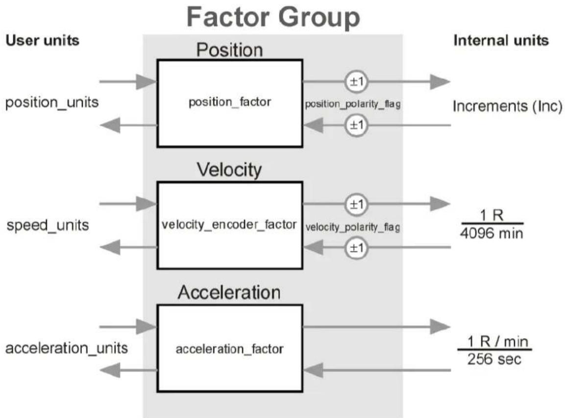
flowchart
```mermaid
graph LR
    subgraph_Factor_Group["Factor Group"]
        direction TB
        A["Position"] --> B["position_factor"]
        B --> C["±1"]
        B --> D["±1"]
        E["Internal units"] --> F["Increments (Inc)"]
    end

    subgraph_Factor_Group_Beta["Factor Group"]
        direction TB
        G["Velocity"] --> H["velocity_encoder_factor"]
        H --> I["±1"]
        H --> J["±1"]
        K["speed_units"] --> L
        M["speed_units"] --> N
        O["speed_units"] --> P
        Q["speed_units"] --> R
        S["speed_units"] --> T
        U["speed_units"] --> V
        W["speed_units"] --> X
        Y["speed_units"] --> Z
        AA["speed Units"] --> AB
        AC["speed Units"] --> AD
        AE["speed Units"] --> AF
        AG["speed Units"] --> AH
        AI["speed Units"] --> AJ
        AK["speed Units"] --> AL
        AM["speed Units"] --> AN
        AO["speed Units"] --> AP
        AQ["speed Units"] --> AQ
        AR["speed Units"] --> AR
        AS["speed Units"] --> AT
        AU["speed Units"] --> AU
        AV["speed Units"] --> AW
        AX["speed Units"] --> AX
        AY["speed Units"] --> AZ
        BA["speed Units"] --> BB
        BC["speed Units"] --> BC
        DA["speed Units"] --> DA
        AE["Speed Units"] --> AE
        AF["Speed Units"] --> AF
        AG["Speed Units"] --> AG
        AH["Speed Units"] --> AH
        AI["Speed Units"] --> AI
        AJ["Speed Units"] --> AJ
        AK["Speed Units"] --> AK
        AL["Speed Units"] --> AL
        AM["Speed Units"] --> AM
        AN["Speed Units"] --> AN
        AO["Speed Units"] --> AO
        AP["Speed Units"] --> AP
        AQ["Speed Units"] --> AQ
        AR["Speed Units"] --> AR
        AS["Speed Units"] --> AS
        AT["Speed Units"] --> AT
        AU["Speed Units"] --> AU
        AV["Speed Units"] --> AV
        AW["Speed Units"] --> AW
        AX["Speed Units"] --> AX
        AO["Speed Units"] --> AO
        AP["Speed Units"] --> AP
        AQ["Speed Units"] --> AQ
        AR["Speed Units"] --> AR
        AS["Speed Units"] --> AS
        AT["Speed Units"] --> AT
        AU["Speed Units"] --> AU
        AV["Speed Units"] --> AV
        AW["Speed Units"] --> AW
        AX["Speed Units"] --> AX
        AO["Speed Units"] --> AO

    %% Note: The chart displays multiple input/output nodes connected by arrows, but the labels on the output are 'acceleration' and 'acceleration_factor'. The values in the table represent the same variable's output value. The times are labeled as '1 R / min / 256 sec'. The number of input units is also shown on the left side.
Fig. 6.2: Factor group
All parameters are stored in the motor controller in its internal units and only converted with the help of the factor group when being written in or read out.
For that reason, the factor group should be set before the first parameter setting and not changed during parameter setting.
6. Setting Parameters
By default, the factor group is set to the following units:
| Size | Description | Unit | Explanation |
| Length | position_units | Increments | 65536 Increments per revolution |
| Velocity | speed_units | min^-1 | Revolutions per minute |
| Acceleration | acceleration_units | (min^-1)/s | RPM increase per second |
6.3.2 Description of the Objects
Objects treated in this chapter
| Index | Object | Name | Type | Attr. |
| 6093_h | ARRAY | position_factor | UINT32 | rw |
| 6094_h | ARRAY | velocity_encoder_factor | UINT32 | rw |
| 6097_h | ARRAY | acceleration_factor | UINT32 | rw |
| 607E_h | VAR | polarity | UINT8 | rw |
Object 6093 _h : position\_factor
The object position_factor converts all length units of the application from position_units into the internal unit increments (65536 increments equal 1 revolution). It consists of numerator and denominator.

Fig. 6.3: Overview: Factor group
6. Setting Parameters
| Index | 6093_h |
| Name | position_factor |
| Object code | ARRAY |
| No. of Elements | 2 |
| Data Type | UINT32 |
| Sub-index | 01_h |
| Description | numerator |
| Access | rw |
| PDO Mapping | yes |
| Units | -- |
| Value Range | -- |
| Default Value | 1 |
| Sub-index | 02_h |
| Description | divisor |
| Access | rw |
| PDO Mapping | yes |
| Units | -- |
| Value Range | -- |
| Default Value | 1 |
The following variables are included in the position_factor calculation formula:
gear_ratio
Gear ratio between revolutions at the drive-in ( R_IN ) and revolutions at the drive-out ( R_OUT )
feed_constant
Ratio between revolutions at the drive-out ( R_OUT ) and movement in position_units (e.g. 1 R = 360°)
Calculation of the position_factor uses the following equation:
$$ \text { position_factor } = \frac {\text { numerator }}{\text { divisor }} = \frac {\text { gear_ratio } \times 6 5 5 3 6}{\text { feed_constant }} $$
The position_factor must be written separately by numerator and denominator into the motor controller. It can therefore be necessary to convert the fraction into whole numbers through suitable expansion.

The position_factor must not be greater than 2^24 .
6. Setting Parameters
EXAMPLE
First, the desired unit (column 1) and the desired decimal positions (DP) must be determined along with the gear factor and, if applicable, the feed constant of the application. This feed constant is then depicted in the desired position units (column 2).
Finally, all values can be placed in the equation and the fraction calculated:

1.) Desired unit at the drive-out (position_units)
2.) feed constant: How many position units are 1 revolution (R out)?
3.) Gear factor (gear_ratio): R IN per ROUT
4.) Insert values into equation
| 1. | 2. | 3. | 4. | RESULTAbbreviated |
| Increments,0 DPInc. | 1R_OUT = 65536 Inc | 1/1 | 1U1U · 65536 65536 Ink1U = 1 Ink1 Ink | num:1div:1 |
| Degree,1 DP1/10 Degree(°/10) | 1R_OUT = 3600^/_10 | 1/1 | 1U1U · 65536 3600%1U = 65536 Ink3600% | num:4096div:225 |
| Rev.,2 DP1/100 Rev.(R/100) | 1R_OUT = 100^R/_100 | 1/1 | 1U1U · 65536 100%1U = 65536 Ink100% | num:16384div:25 |
| 2/3 | 2U3U · 65536 100%1U = 131072 Ink300% | num:32768div:75 | ||
| mm,1 DP1/10 mm(mm/10) | 63.15^mn/_R 1R_OUT = 631.5^mn/_10 | 4/5 | 4U5U · 65536 631.5^mn/_101U = 2621440 Ink31575^mn/_10 | num:524288div:6315 |
6. Setting Parameters
6094h: velocity\_encoder\_factor
The object velocity_encoder_factor converts all speed values of the application from speed_units into the internal unit Revolutions per 4096 minutes. It consists of numerator and denominator.
| Index | 6094_h |
| Name | velocity_encoder_factor |
| Object code | ARRAY |
| No. of Elements | 2 |
| Data Type | UINT32 |
| Sub-index | 01_h |
| Description | numerator |
| Access | rw |
| PDO Mapping | yes |
| Units | -- |
| Value Range | -- |
| Default Value | 1000_h |
| Sub-index | 02_h |
| Description | divisor |
| Access | rw |
| PDO Mapping | yes |
| Units | -- |
| Value Range | -- |
| Default Value | 1 |
Calculation of the velocity_encoder_factor consists in principle of two parts: a conversion factor from internal length units into position_units, and a conversion factor from internal time units into user-defined time units (e.g. from seconds into minutes). The first part corresponds to the calculation of the position_factor; for the second part, an additional factor is added to the calculation:
time_factor_v
Ratio between internal time unit and user-defined time unit.
$$ \text {(e.g. 1 min =} ^ {1} / _ {4 0 9 6} 4 0 9 6 \text {min)} $$
gear_ratio
Gear ratio between revolutions at the drive-in ( R_IN ) and revolutions at the drive-out ( R_OUT )
feed_constant
Ratio between revolutions at the drive-out ( R_OUT ) and movement in position_units (e.g. 1 R = 360°)
6. Setting Parameters
The calculation of the velocity_encoder_factor uses the following equation:

Like the position_factor, the velocity_encoder_factor is also written into the motor controller separated by numerator and denominator. It can therefore be necessary to convert the fraction into whole numbers through suitable expansion.
EXAMPLE
First, the desired unit (column 1) and the desired decimal positions (DP) must be determined along with the gear factor and, if applicable, the feed constant of the application. This feed constant is then depicted in the desired position units (column 2). Then the desired time unit is converted into the time unit of the motor controller (column 3). Finally, all values can be placed in the equation and the fraction calculated:

other
| Stage | Value | |---|---| | 1/10 | 631.5 | | 4/5 | 4096.60 | | 1U | 631.5 | | 1U | 1966080 | | 1U | 6315 | | 1U | 421 | | 1U | 43.15 | | 1U | 631.5 | | 1U | 60.75 | | 1U | 60.75 | The diagram shows a process with three distinct stages connected by arrows indicating direction.1.1 Desired unit at the drive-out (speed units)
6. Setting Parameters
| (^°/_10s) | 60^min = 60 · 40964096min | ||||
| mm/s1 CP 1/10^mm/s(^mm/10s) | 63.15^mm/s 1 R_0.77 = 631.5^mm/10 | 160^min = 60 · 4096 14096min | 4/5 | 4U · 60 · 40961/c631.5%1U = 1966080%6315% | num:131072div:412 |
Object 6097: acceleration\_factor
The object acceleration_factor converts all acceleration values of the application from acceleration_units into the internal unit Revolutions per minute per 256 seconds. It consists of numerator and denominator.
| Index | 6097 _n |
| Name | acceleration_factor |
| Object code | ARRAY |
| No. of Elements | 2 |
| Data Type | UINT32 |
| Sub-index | 01 _n |
6. Setting Parameters
Calculation of the acceleration_factor consists of two parts: a conversion factor from internal length units into position_units, and a conversion factor from internal time units squared into user-defined time units squared (e.g. from seconds ^2 into minutes ^2 ). The first part corresponds to the calculation of the position_factor; for the second part, an additional factor is added:
time_factor_a Ratio between internal times units squared and unser-defined time unit squared
$$ \text {(e.g. 1 min} ^ {2} = 1 \text { min } \cdot 1 \text { min } = 6 0 \text { s } \cdot 1 \text { min } = ^ {6 0} / _ {2 5 6} 2 5 6 \text { min } \cdot \mathbf {s}) $$
gear_ratio Gear ratio between revolutions at the drive-in ( R_IN ) and revolutions at the drive-out ( R_OUT )
feed_constant Ratio between revolutions at the drive-out ( R_OUT ) and movement in position_units (e.g. 1 R = 360°)
Calculation of the acceleration_factor uses the following equation:
$$ \text { acceleration_factor } = \frac {\text { numerator }}{\text { divisor }} = \frac {\text { gear_ratio } \times \text { time_factor_a }}{\text { feed_constant }} $$
The acceleration_factor is also written into the motor controller separated by numerator and denominator, so it may have to be expanded.
6. Setting Parameters
EXAMPLE
First, the desired unit (column 1) and the desired decimal positions (DP) must be determined along with the gear factor and, if applicable, the feed constant of the application. This feed constant is then depicted in the desired position units (column 2). Then the desired time unit ^2 is converted into the time unit ^2 of the motor controller (column 3). Finally, all values can be placed in the equation and the fraction calculated:

1.) Desired unit at the drive-out (acceleration_units)
2.) feed constant: How many position units are 1 revolution (Rox)?
3.) time factor a: Desired time unit2 per internal time unit2
4.) Gear factor (gear_ratio) R_B per R_B
5.) Insert values into equation
| 1. | 2. | 3. | 4. | 5. | RESULTAbbreviated |
| R/min/s0 DP ^ /min.s | 1 R_OUT =1 U_OUT | 11.s = 1256 258.s | 1/1 | 1U1U · 256%_258.mos1%_258.s = 256%_258.mos1%_258.s | num: 256div: 1 |
| 11 |
6. Setting Parameters
Object 607E _h : polarity
The algebraic sign of the position and speed values of the motor controller can be set with the corresponding polarity_flag. This can serve to invert the motor's direction of rotation with the same nominal values.
In most applications, it makes sense to set the position_polarity_flag and the velocity_polarity_flag to the same value.
Setting of the polarity_flag influences only parameters when reading and writing. Parameters already present in the motor controller are not changed.
| Index | 607E_h |
| Name | polarity |
| Object code | VAR |
| Data Type | UINT8 |
| Access | rw |
| PDO Mapping | yes |
| Units | -- |
| Value Range | 40_h, 80_h, CO_h |
| Default Value | 0 |
| Bit | Value | Name | Meaning | |
| 6 | 40_h | velocity_polarity_flag | 0: multiply by 1 (default) | multiply by 1 |
| 1: multiply by -1 (inverse) | multiply by -1 | |||
| 7 | 80_h | position_polarity_flag | 0: multiply by 1 (default) | multiply by 1 |
| 1: multiply by -1 (inverse) | multiply by -1 | |||
6.4 Final stage parameters
6.4.1 Overview
The mains voltage is fed into the final stage via a pre-charged switch. When the power supply is switched on, the switch-on current is limited and charging is monitored. After pre-charging of the intermediate circuit, the charging switch is bypassed. This condition is a prerequisite for controller enable. The rectified mains voltage is smoothed out by the capacitors of the intermediate circuit. From the intermediate circuit, the motor is fed via the IGBTs. The final stage contains a series of safety functions, some of which can be parameterised:
- Controller enable logic (software and hardware release)
- Excess current monitoring
- Excess voltage / under-voltage monitoring of the intermediate circuit
• Power section monitoring
6.4.2 Description of the Objects
| Index | Object | Name | Type | Attr. |
| 6510_h | VAR | drive_data |
Object 6510 _h - 10 _h : enable\_logic
To be able to activate the final stage of the motor controller, the digital inputs final stage enable and controller enable must be set: The final stage enable works directly on the control signals of the power transistors and could also interrupt them in case of a defective microprocessor. Removal of the final stage enable with a running motor thus causes the motor to spin out unbraked or makes it stoppable only with the holding brake that might be available. The controller enable is processed by the microcontroller of the motor controller. After removal of this signal, the motor controller reacts differently, depending on the operation mode:
- Positioning mode and velocity-controlled mode
After removal of the signal, the motor is braked following a defined braking ramp.
The final stage is not shut off until the motor rotation speed is below 10 min^-1 and the holding brake, if present, has been applied.
- Torque-controlled operation
The final stage is shut off immediately after removal of the signal. Simultaneously, the holding brake, if present, is applied. The motor thus spins out or is stopped only by the holding brake, if present.

Warning
Potentially fatal voltage!
The two signals do not ensure that current is shut off to the motor.
During operation of the motor controller via the CAN bus, the two digital inputs final stage enable and controller enable are both set to 24 V, and the enable is controlled via the CAN bus. For this, the object 6510_h – 10_h (enable_logic) must be set to two. For safety reasons, this takes place automatically on activation of CANopen (also after a reset of the motor controller).
| Index | 6510_h |
| Name | drive_data |
| Object code | RECORD |
| No. of Elements | 51 |
6. Setting Parameters
| Sub-index | 10_h |
| Description | enable_logic |
| Data Type | UINT16 |
| Access | rw |
| PDO Mapping | no |
| Units | -- |
| Value Range | 0 ... 2 |
| Default Value | 2 |
| Value | Meaning |
| 0 | Digital inputs final stage enable + controller enable |
| 1 | Digital inputs final stage enable + controller enable + RS232 |
| 2 | Digital inputs final stage enable + controller enable + CAN |
Object 6510 _h 30 _h : pwm\_frequency
The switching losses of the final stage are proportional to the switching frequency of the power transistors. Halving the normal PWM frequency makes it possible to take somewhat more power out of some devices of the CMMP family. But this increases the current ripple caused by the final stage. This switchover is only possible when the final stage is switched off.
| Sub-index | 30_h |
| Description | pwm_frequency |
| Data Type | UINT16 |
| Access | rw |
| PDO Mapping | no |
| Units | -- |
| Value Range | 0, 1 |
| Default Value | 0 |
| Value | Meaning |
| 0 | Normal final stage frequency |
| 1 | Half final stage frequency |
Object 6510 _h — 3A _h : enable\_enhanced\_modulation
The object enable_enhanced_modulation can activate the extended sinus modulation. It permits better use of the intermediate circuit voltage and thus about 14 % higher speeds. A disadvantage in certain applications is that the regulating action and smooth running of the motor are a little worse at very low speeds. Write access is only possible when the final stage is switched off. To adopt the change, the parameter set must be secured and a reset performed.
6. Setting Parameters
| Sub-index | 3A_h |
| Description | enable_enhanced_modulation |
| Data Type | UINT16 |
| Access | rw |
| PDO Mapping | no |
| Units | -- |
| Value Range | 0, 1 |
| Default Value | 0 |
| Value | Meaning |
| 0 | Extended sinus modulation OFF |
| 1 | Extended sinus modulation ON |

Activation of the extended sinus modulation only becomes effective after a reset. The parameter set must first be stored (save_all_parameters) and then a reset performed.
Object 6510 _h \_31 _h : power\_stage\_temperature
The temperature of the final stage can be read out via the object power_stage_temperature. When the temperature specified in the object 6510_h-32_h (max_power_stage_temperature) is exceeded, the final stage shuts off and an error message is issued.
| Sub-index | 31_h |
| Description | power_stage_temperature |
| Data Type | INT16 |
| Access | ro |
| PDO Mapping | yes |
| Units | °C |
| Value Range | -- |
| Default Value | .. |
6. Setting Parameters
Object 6510 _h 32 _h : max\_power\_stage\_temperature
The temperature of the final stage can be read out via the object 6510_h-31_h (power_stage_temperature). When the temperature specified in the object max_power_stage_temperature is exceeded, the final stage shuts off and an error message is emitted.
| Sub-index | 32_h |
| Description | max_power_stage_temperature |
| Data Type | INT16 |
| Access | ro |
| PDO Mapping | no |
| Units | °C |
| Value Range | 100 |
| Default Value | device-dependent |
| Device type | Value |
| CMMP-AS-C2-3A | 100 °C |
| CMMP-AS-C5-3A | 80 °C |
| CMMP-AS-C5-11A-P3 | 80 °C |
| CMMP-AS-C10-11A-P3 | 80 °C |
Object 6510 _h 33 _h : nominal dc link circuit voltage
The device nominal voltage in millivolts can be read out via the object nominal_dc_link_circuit_voltage.
| Sub-index | 33_h |
| Description | nominal_dc_link_circuit_voltage |
| Data Type | UINT32 |
| Access | ro |
| PDO Mapping | no |
| Units | mV |
| Value Range | -- |
| Default Value | device-dependent |
| Device type | Value |
| CMMP-AS-C2-3A | 360000 |
| CMMP-AS-C5-3A | 360000 |
| CMMP-AS-C5-11A-P3 | 560000 |
| CMMP-AS-C10-11A-P3 | 560000 |
6. Setting Parameters
Object 6510h \_ 34h: actual\_dc\_link\_circuit\_voltage
The actual voltage of the intermediate circuit in millivolts can be read out via the object actual_dc_link_circuit_voltage.
| Sub-index | 34_h |
| Description | actual_dc_link_circuit_voltage |
| Data Type | UINT32 |
| Access | ro |
| PDO Mapping | yes |
| Units | mV |
| Value Range | -- |
| Default Value | -- |
Object 6510 _h 35 _h : max dc link circuit voltage
The object max_dc_link_circuit_voltage specifies from which intermediate circuit voltage the final stage, for safety reasons, is immediately switched off and an error message issued.
| Sub-index | 35_h |
| Description | max_dc_link_circuit_voltage |
| Data Type | UINT32 |
| Access | ro |
| PDO Mapping | no |
| Units | mV |
| Value Range | -- |
| Default Value | device-dependent |
| Device type | Value |
| CMMP-AS-C2-3A | 460000 |
| CMMP-AS-C5-3A | 460000 |
| CMMP-AS-C5-11A-P3 | 800000 |
| CMMP-AS-C10-11A-P3 | 800000 |
6. Setting Parameters
Object 6510 _h 36 _h : min dc link circuit voltage
The motor controller has an undervoltage monitor. It can be activated via the object 6510_h-37_h (enable_dc_link_undervoltage_error). The object 6510_h-36_h (min_dc_link_circuit_voltage) specifies the lower intermediate circuit voltage the motor controller should work up to. Below this voltage, the error E 02-0 is triggered if it was activated by the following object.
| Sub-index | 36_h |
| Description | min_dc_link_circuit_voltage |
| Data Type | UINT32 |
| Access | rw |
| PDO Mapping | no |
| Units | mV |
| Value Range | 0 ... 1 000 000 |
| Default Value | 0 |
Object 6510 _h 37 _h : enable dc link undervoltage error
The undervoltage monitor can be activated with the object enable_dc_link_undervoltage_error. In the object 6510_h-36_h (min_dc_link_circuit_voltage), specify the lower intermediate circuit voltage the motor controller should work up to.
| Sub-index | 37_h |
| Description | enable_dc_link_undervoltage_error |
| Data Type | UINT16 |
| Access | rw |
| PDO Mapping | no |
| Units | -- |
| Value Range | 0, 1 |
| Default Value | 0 |
| Value | Meaning |
| 0 | Undervoltage error OFF (reaction WARNING) |
| 1 | Undervoltage error ON (Reaction CONTROLLER ENABLE OFF) |
The error 02-0 is activated through a change of the error reaction. Reactions that lead to shutting down of the drive are returned as ON, all others as OFF. When writing with 0, the error reaction WARNING is set, when writing with 1 the error reaction CONTROLLER ENABLE OFF.
See also chapter 6.18, Error management.
6. Setting Parameters
Object 6510 _h \_40 _h : nominal\_current
The device nominal current can be read out with the object nominal_current. It is simultaneously the upper limit value that can be written into the object 6075_h (motor_rated_current).
| Sub-index | 40_h |
| Description | nominal_current |
| Data Type | UINT32 |
| Access | ro |
| PDO Mapping | no |
| Units | mA |
| Value Range | -- |
| Default Value | device-dependent |
| Device type | Value |
| CMMP-AS-C2-3A | 2500 |
| CMMP-AS-C5-3A | 5000 |
| CMMP-AS-C5-11A-P3 | 2500 |
| CMMP-AS-C10-11A-P3 | 5000 |

Due to the power derating, other values may be displayed, depending on the controller cycle time and the final stage cycle frequency.
Object 6510 _h - 41 _h : peak\_current
The device peak current can be read out with the object peak_current. It is simultaneously the upper limit value that can be written into the object 6073_h (max_current).
| Sub-index | 41_h |
| Description | peak_current |
| Data Type | UINT32 |
| Access | ro |
| PDO Mapping | no |
| Units | mA |
| Value Range | -- |
| Default Value | device-dependent |
6. Setting Parameters
| Device type | Value |
| CMMP-AS-C2-3A | 5000 |
| CMMP-AS-C5-3A | 10000 |
| CMMP-AS-C5-11A-P3 | 7500 |
| CMMP-AS-C10-11A-P3 | 15000 |

Due to the power derating, other values may be displayed, depending on the controller cycle time and the final stage cycle frequency.
6.5 Current Regulator and Motor Adjustment

Caution
Incorrect settings of the current regulator parameters and current limits can destroy the motor and, possibly, also the motor controller within a very short time!
6.5.1 Overview
The parameter set of the motor controller must be adapted for the connected motor and the set of cables used. Affected are the following parameters:
Nominal current dependent on the motor
Overload capacity dependent on the motor
Number of pins dependent on the motor
Current Control dependent on the motor
Direction of rotation dependent on the motor and on the phase sequence in the motor and angle transmitter cable
Offset angle dependent on the motor and on the phase sequence in the motor and angle transmitter cable
These data must be determined the first time a motor type is used with the parameterisation software. For the Festo motor series EMMS-AS, you will find the parameter sets on your installation CD. You will find additional parameter sets in the Internet under www.festo.com/download.
Please note that the direction of rotation and offset angle also depend on the set of cables used. The parameter sets therefore work only with identical cabling.

Caution
If the phase sequence is distorted in the motor or angle transmitter cable, the result may be positive feedback, so the speed in the motor cannot be regulated. The motor can turn uncontrollably!
6.5.2 Description of the Objects
| Index | Object | Name | Type | Attr. |
| 6075_h | VAR | motor_rated_current | UINT32 | rw |
| 6073_h | VAR | max_current | UINT16 | rw |
| 604D_h | VAR | pole_number | UINT8 | rw |
| 6410_h | RECORD | motor_data | rw | |
| 60F6_h | RECORD | torque_control_parameters | rw |
Affected objects from other chapters
| Index | Object | Name | Type | Chapter |
| 2415_n | RECORD | current_limitation | 0 Nominal value limitation |
Object 6075h: motor\_rated\_current
This value can be taken from the motor rating plate and is entered in milliamperes. The effective value (RMS) is always assumed. No current can be set above the motor controller nominal current ( 6510_h- 40_h : nominal_current).
| Index | 6075h |
| Name | motor_rated_current |
| Object code | VAR |
| Data Type | UINT32 |
| Access | rw |
| PDO Mapping | yes |
| Units | mA |
| Value Range | 0 ... nominal_current |
| Default Value | 296 |

If a new value is written in the object 6075_h (motor_rated_current), the object 6073_h (max_current) must also always be newly parameterised.
6. Setting Parameters
Object 6073 _h : max\_current
Servo motors may normally be overloaded for a certain time period. The highest permissible motor current is set with this object. It refers to the motor rated current (object 6075 h : motor_rated_current) and is set in thousandths. The value range is limited upward by the maximum controller current (object 6510 h - 41 _h : peak_current). Many motors may be overloaded by a factor of 2 for a short time. In this case, write the value 2000 in this object.

The object 6073_h (max_current) may only be written when the object 6075_h (motor_rated_current) was previously validly written.
| Index | 6073_h |
| Name | max_current |
| Object code | VAR |
| Data Type | UINT16 |
| Access | rw |
| PDO Mapping | yes |
| Units | per thousands of rated current |
| Value Range | -- |
| Default Value | 2023 |
Object 604D _h : pole\_number
The number of poles of the motor can be obtained from the motor datasheet or the parameterisation software. The number of poles is always an even number. Often, the number of pole pairs is given instead of the number of poles. The number of poles then equals twice the number of pole pairs.
This object is not changed through restore_default_parameters.
| Index | 604D_h |
| Name | pole_number |
| Object code | VAR |
| Data Type | UINT8 |
| Access | rw |
| PDO Mapping | yes |
| Units | -- |
| Value Range | 2 ... 254 |
| Default Value | 4 (after INIT!) |
6. Setting Parameters
Object 6410 _h \_ 03 _h : iit\_time\_motor
Servo motors may normally be overloaded for a certain time period. This object specifies how long the current specified in the object 6073_h (max_current) can be applied to the connected motor. After the IIT time has elapsed, the current is automatically limited to the value set in the object 6075_h (motor_rated_current) to protect the motor. The standard setting is two seconds and is valid for most motors.
| Index | 6410_h |
| Name | motor_data |
| Object code | RECORD |
| No. of Elements | 5 |
| Sub-index | 03_h |
| Description | iit_time_motor |
| Data Type | UINT16 |
| Access | rw |
| PDO Mapping | no |
| Units | ms |
| Value Range | 0 ... 10000 |
| Default Value | 2000 |
Object 6410 _h \_ 04 _h : iit\_ratio\_motor
With the object iit_ratio_motor, the actual capacity utilization of the I²t limitation can be read out in per thousands.
| Sub-index | 04_h |
| Description | iit_ratio_motor |
| Data Type | UINT16 |
| Access | ro |
| PDO Mapping | no |
| Units | per thousand |
| Value Range | -- |
| Default Value | -- |
6. Setting Parameters
Object 6510 _h 38 _h : iit\_error\_enable
The object iit_error_enable determines how the motor controller acts when the I^2 t limitation occurs. Either it is only shown in the statusword, or error E 31-0 is triggered.
| Index | 6510_h |
| Name | drive_data |
| Object code | RECORD |
| No. of Elements | 51 |
| Sub-index | 38_h |
| Description | iit_error_enable |
| Data Type | UINT16 |
| Access | rw |
| PDO Mapping | no |
| Units | -- |
| Value Range | 0, 1 |
| Default Value | 0 |
| Value | Meaning | |
| 0 | I^2t error OFF | (priority WARNING) |
| 1 | I^2t error ON | (Priority CONTROLLER ENABLE OFF) |
The error 31-0 is activated through a change of the error reaction. Reactions that lead to shutting down of the drive are returned as ON, all others as OFF. When writing with 0, the error reaction WARNING is set, when writing with 1 the error reaction CONTROLLER ENABLE OFF. See cchapter 6.18, Error management.
Object 6410 _h \_ 10 _h : phase\_order
In the phase sequence (phase_order), distortions between motor cable and angle transmitter cable are considered. It can be taken from the parameterisation software. A zero equals "right", a one "left".
| Sub-index | 10_h |
| Description | phase_order |
| Data Type | INT16 |
| Access | rw |
| PDO Mapping | yes |
| Units | -- |
| Value Range | 0, 1 |
| Default Value | 0 |
6. Setting Parameters
| Value | Meaning |
| 0 | right |
| 1 | Left |
Object 6410 _h - 11 _h : encoder\_offset\_angle
The servo motors used have permanent magnets on the rotor. These generate a magnetic field, whose orientation toward the stator depends on the rotor position. For electronic commutation, the motor controller must always set the electromagnetic field of the stator in the correct angle to this permanent magnet field. To do this, it constantly determines the rotor position with an angle transmitter (resolver, etc.).
The orientation of the angle transmitter to the permanent magnetic field must be entered in the object encoder_offset_angle. This angle can be determined with the parameterisation software. The angle determined by the parameterisation software lies around ±180^ . It must be calculated as follows:
$$ \text { encoder_offset_angle } = \text {"offset angle of the angle encoder"} \times \frac {3 2 7 6 7}{1 8 0 ^ {\circ}} $$
This object is not changed through restore_default_parameters.
| Index | 6410_h |
| Name | motor_data |
| Object code | RECORD |
| No. of Elements | 5 |
| Sub-index | 11_h |
| Description | encoder_offset_angle |
| Data Type | INT16 |
| Access | rw |
| PDO Mapping | yes |
| Units | ... |
| Value Range | -32767 ... 32767 |
| Default Value | E000h (-45°) (after INIT!) |
6. Setting Parameters
Object 6410 _h — 14 _h : motor\_temperature\_sensor\_polarity
This object can be used to determine whether an opener or a closer is used as digital motor temperature sensor.
| Sub-index | 14_h |
| Description | motor_temperature_sensor_polarity |
| Data Type | INT16 |
| Access | rw |
| PDO Mapping | yes |
| Units | -- |
| Value Range | 0, 1 |
| Default Value | 0 |
| Value | Meaning |
| 0 | Normally closed contact |
| 1 | N/O contact |
Object 6510 _h — 2E _h : motor\_temperature
With this object, the actual motor temperature can be read out if an analogue temperature sensor is connected. Otherwise, the object is undefined.
| Index | 6510_h |
| Name | drive_data |
| Object code | RECORD |
| No. of Elements | 51 |
| Sub-index | 2E_h |
| Description | motor_temperature |
| Data Type | INT16 |
| Access | ro |
| PDO Mapping | yes |
| Units | °C |
| Value Range | -- |
| Default Value | -- |
6. Setting Parameters
Object 6510 _h - 2F _h : max\_motor\_temperature
If the motor temperature defined in this object is exceeded, a reaction occurs in accordance with Error management (error 3-0, Excess temperature in motor analogue). If a reaction is parameterised that results in shutting down the drive, an emergency message is sent.
For parameterisation of the error management, see chapter 6.18.
| Sub-index | 2F_h |
| Description | max_motor_temperature |
| Data Type | INT16 |
| Access | rw |
| PDO Mapping | no |
| Units | °C |
| Value Range | 20 ... 300 |
| Default Value | 100 |
Object 60F6h: torque\_control\_parameters
The data of the current controller must be taken from the parameterisation software. Attention must be paid to the following calculations:
The amplification of the current controller must be multiplied by 256. With an amplification of 1.5 in the "Current Controller" menu of the parameterisation software, the value 384 = 180_h must be written in the object torque_control_gain.
The current controller time constant is specified in the parameterisation software in milliseconds. To transfer this time constant into the torque_control_time object, it must previously be converted into microseconds. With a specified time of 0.6 milliseconds, the corresponding value 600 is entered in the object torque_control_time.
| Index | 60F6h |
| Name | torque_control_parameters |
| Object code | RECORD |
| No. of Elements | 2 |
| Sub-index | 01_h |
| Description | torque_control_gain |
| Data Type | UINT16 |
| Access | rw |
| PDO Mapping | no |
| Units | 256 = “1” |
| Value Range | 0 ... 32 * 256 |
| Default Value | 3 * 256 (768) |
| Sub-index | 02_h |
| Description | torque_control_time |
| Data Type | UINT16 |
| Access | rw |
| PDO Mapping | no |
| Units | μs |
| Value Range | 104 ... 64401 |
| Default Value | 1020 |
6.6 Speed regulator
6.6.1 Overview
The parameter set of the motor controller must be adapted for the application. In particular, the amplification is strongly dependent on masses that may be connected to the motor. The data must be optimally determined during system start-up using the parameterisation software.

Caution
Incorrect setting of the speed regulator parameters can result in strong vibrations and possibly destroy parts of the system!
6.6.2 Description of the Objects
| Index | Object | Name | Type | Attr. |
| 60F9_h | RECORD | velocity_control_parameters | rw | |
| 2073_h | VAR | velocity_display_filter_time | UINT32 | rw |
Objekt 60F9h: velocity\_control\_parameters
The data of the velocity controller must be taken from the parameterisation software. Attention must be paid to the following calculations:
The amplification of the velocity controller must be multiplied by 256.
With a gain of 1.5 in the "Velocity controller" menu of the parameterisation software, the value 384 = 180_h must be written in the object velocity_control_gain.
The velocity controller time constant is specified in the parameterisation software in milliseconds. To transfer this time constant into the velocity_control_time object, it must previously be converted into microseconds. With a specified time of 2.0 milliseconds, the corresponding value 2000 is entered in the object velocity_control_time.
6. Setting Parameters
| Index | 60F9h |
| Name | velocity_control_parameter_set |
| Object code | RECORD |
| No. of Elements | 3 |
| Sub-index | 01_h |
| Description | velocity_control_gain |
| Data Type | UINT16 |
| Access | rw |
| PDO Mapping | no |
| Units | 256 = Gain 1 |
| Value Range | 20 ... 64 * 256 (16384) |
| Default Value | 256 |
| Sub-index | 02_h |
| Description | velocity_control_time |
| Data Type | UINT16 |
| Access | rw |
| PDO Mapping | no |
| Units | μs |
| Value Range | 1 ... 32000 |
| Default Value | 2000 |
| Sub-index | 04_h |
| Description | velocity_control_filter_time |
| Data Type | UINT16 |
| Access | rw |
| PDO Mapping | no |
| Units | μs |
| Value Range | 1 ... 32000 |
| Default Value | 400 |
6. Setting Parameters
Object 2073h: velocity\_display\_filter\_time
The object velocity_display_filter_time can be used to set the filter time of the velocity display value filter.
| Index | 2073_h |
| Name | velocity_display_filter_time |
| Object code | VAR |
| Data Type | UINT32 |
| Access | rw |
| PDO Mapping | no |
| Units | μs |
| Value Range | 1000 ... 50000 |
| Default Value | 20000 |

Please remember that the object velocity_actual_value_filtered is used for turn-through protection. In case of very large filter times, a turn-through error is recognised only after a corresponding delay.
6.7 Position Controller (Position Control Function)
6.7.1 Overview
This chapter describes all parameters required for the position controller. The position nominal value (position_demand_value) of the curve generator is applied to the input of the position controller. In addition, the actual position value (position_actual_value) is added by the angle transmitter (resolver, incremental transmitter, etc.). The actions of the position controller can be influenced by parameters. It is possible to limit the output variable (control_effort) to keep the position control circuit stable. The output variable is supplied to the velocity controller as the speed command value. All input and output variables of the position controller are converted in the Factor Group from the application-specific units into the respective internal units of the regulator.
The following subfunctions are defined in this chapter:
1. Following error (Following\_Error)
The following error is the deviation of the position feedback value (position_actual_value) from the position command value (position_demand_value). If this following error is greater than specified in the following error window (following_error_window) for a specific time period, bit 13 following_error is set in the object statusword. The permitted time period can be specified via the object following_error_time_out.
6. Setting Parameters
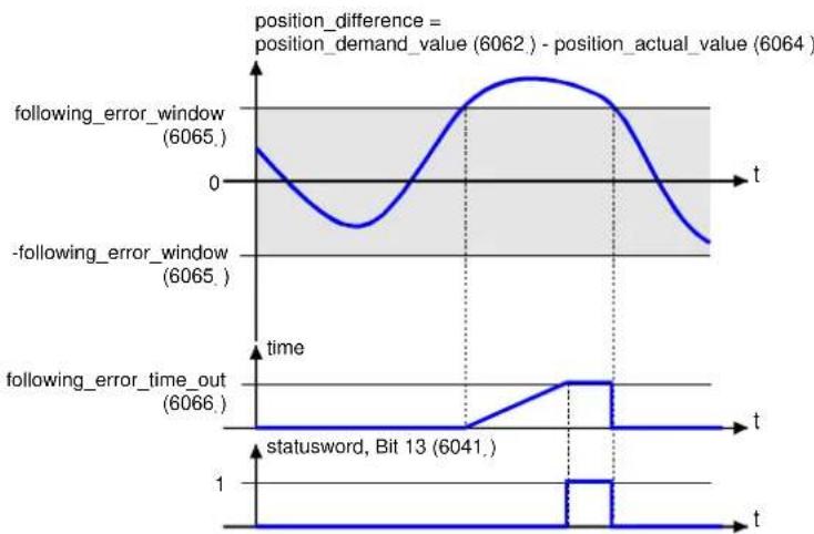
line
| time | following_error_window | -following_error_window | following_error_time_out | |------|------------------------|--------------------------|---------------------------| | 0 | 6065 | 6065 | 6066 | | 1 | 6064 | 6064 | 6066 |Fig. 6.4: Contouring error – functional overview
The Fig. 6.5 shows how the window function is defined for the "contouring error" message. The area between x_j - x_0 and x_j + x_0 is defined symmetrically around the command position (position_demand_value) x_j . For example, the positions x_t2 and x_t3 lie outside this window (following_error_window). If the drive leaves this window and does not return to the window within the time specified in the object following_error_time_out, bit 13 following_error is set in the statusword.

Fig. 6.5: Drag error
2. Position reached
This function offers the possibility of defining a position window around the target position (target_position). If the actual position of the drive is located within this range for a specific time – the position_window_time – the related bit 10 (target_reached) is set in the statusword.
6. Setting Parameters

line
| position_window | position_window_time | statusword, Bit 10 | | --------------- | ------------------- | ------------------ | | 6067 | 0 | 0 | | 6068 | 0 | 0 | | 6064 | 0 | 1 |Fig. 6.6: Position reached – functional overview
The Fig. 6.7 shows how the window function is defined for the "position reached" message. The area between x_i - x_0 and x_i + x_0 is defined symmetrically around the target position (target_position) x_i . For example, the positions x_t0 and x_t1 lie outside this position window (position_window). If the drive is located in this window, a timer is started in the motor controller. If this timer reaches the time specified in the object position_window_time and the drive continuously remains in the valid range between x_i - x_0 and x_i + x_0 during this time, bit 10 target_reached is set in the statusword. As soon as the drive leaves the permissible range, both bit 10 and the timer are set to zero.

Fig. 6.7: Position reached
6.7.2 Description of the Objects
Objects treated in this chapter
| Index | Object | Name | Type | Attr. |
| 202D_h | VAR | position_demand_sync_value | INT32 | ro |
| 2030h | VAR | set_position_absolute | INT32 | wo |
| 6062h | VAR | position_demand_value | INT32 | ro |
| 6063_h | VAR | position_actual_value* | INT32 | ro |
| 6064_h | VAR | position_actual_value | INT32 | ro |
| 6065_h | VAR | following_error_window | UINT32 | rw |
| 6066_h | VAR | following_error_time_out | UINT16 | rw |
| 6067_h | VAR | position_window | UINT32 | rw |
| 6068_h | VAR | position_window_time | UINT16 | rw |
| 607B_h | ARRAY | position_range_limit | INT32 | rw |
| 60FA_h | VAR | control_effort | INT32 | ro |
| 60FB_h | RECORD | position_control_parameter_set | rw | |
| 60FC_h | VAR | position_demand_value* | INT32 | ro |
| 6510_h\_20_h | VAR | position_range_limit_enable | UINT16 | rw |
| 6510_h\_22_h | VAR | position_error_switch_off_limit | UINT32 | rw |
Affected objects from other chapters
| Index | Object | Name | Type | Chapter |
| 607A_h | VAR | target_position | INT32 | 8.3 Positioning operating mode |
| 607C_h | VAR | home_offset | INT32 | 8.2 Homing |
| 607D_h | VAR | software_position_limit | INT32 | 8.3 Positioning operating mode |
| 607E_h | VAR | polarity | UINT8 | 6.3 Conversion factors |
| 6093_h | VAR | position_factor | UINT32 | 6.3 Conversion factors |
| 6094_h | ARRAY | velocity_encoder_factor | UINT32 | 6.3 Conversion factors |
| 6096_h | ARRAY | acceleration_factor | UINT32 | 6.3 Conversion factors |
| 6040_h | VAR | controlword | INT16 | 7.1.3 Controlword (control word) |
| 6041_h | VAR | statusword | UINT16 | 7.1.5 Statuswords (status word) |
6. Setting Parameters
Object 60FB _h : position\_control\_parameter\_set
The parameter set of the motor controller must be adapted for the application. The data of the position controller must be optimally determined during system start-up using the parameterisation software.

Caution
Incorrect setting of the position regulator parameters can result in strong vibrations and possibly destroy parts of the system!
The position controller compares the target location with the actual location and, from the difference, creates a correctionspeed 60FA_n : control_effort), which is fed to the speed regulator, taking into account the gain and possibly the integrator. The position controller is relatively slow, compared to the current and velocity controller. Therefore, the controller works internally with activation, so the stabilisation work for the position controller is minimised and the controller can rapidly stabilise.
A proportional link normally suffices as position controller. The amplification of the position controller must be multiplied by 256. With an amplification of 1.5 in the "Position Controller" menu of the parameterisation software, the value 384 must be written in the object position_control_gain.
The position controller normally does not need an integrator. Then the value zero must be written into the object position_control_time. Otherwise, the time constant of the position controller must be converted into microseconds. With a time of 4.0 milliseconds, the corresponding value 4000 is entered in the object position_control_time.
Since the position controller already converts the smallest position deviations into appreciable correction speeds, in the case of a brief disturbance (e.g. brief jamming of the system) it would lead to very major stabilisation processes with very large correction speeds. This can be avoided if the output of the position controller is sensibly limited via the object position_control_v_max (e.g. 500 min ^-1 ).
The size of the position deviation up to which the positon controller will not intervene (dead area) can be defined with the object position_error_tolerance_window. This can be used for stabilisation, such as when there is play in the system.
| Index | 60FB_h |
| Name | position_control_parameter_set |
| Object code | RECORD |
| No. of Elements | 4 |
6. Setting Parameters
| Sub-index | 01_h |
| Description | position_control_gain |
| Data Type | UINT16 |
| Access | rw |
| PDO Mapping | no |
| Units | 256 = "1" |
| Value Range | 0 ... 64 * 256 (16384) |
| Default Value | 102 |
| Sub-index | 02_n |
| Description | position_control_time |
| Data Type | UINT16 |
| Access | ro |
| PDO Mapping | no |
| Units | μs |
| Value Range | 0 |
| Default Value | 0 |
| Sub-index | 04_h |
| Description | position_control_v_max |
| Data Type | UINT32 |
| Access | rw |
| PDO Mapping | no |
| Units | speed units |
| Value Range | 0 ... 131072 min^-1 |
| Default Value | 500 min^-1 |
| Sub-index | 05_h |
| Description | position_error_tolerance_window |
| Data Type | UINT32 |
| Access | rw |
| PDO Mapping | no |
| Units | position units |
| Value Range | 1 ... 65536 (1 R) |
| Default Value | 2 (1/32768 R) |
6. Setting Parameters
Object 6062 _h : position\_demand\_value
The actual nominal position can be read out via this object. The curve generator feeds this into the position controller.
| Index | 6062_h |
| Name | position_demand_value |
| Object code | VAR |
| Data Type | INT32 |
| Access | ro |
| PDO Mapping | yes |
| Units | position units |
| Value Range | -- |
| Default Value | -- |
Object 202D _h : position\_demand\_sync\_value
The actual nominal position can be read out via this object. This is defined by the object 2022_h synchronization_encoder_select (chapter 6.11). This object is specified in user-defined increments.
| Index | 202D_h |
| Name | position_demand_sync_value |
| Object code | VAR |
| Data Type | INT32 |
| Access | ro |
| PDO Mapping | no |
| Units | position units |
| Value Range | -- |
| Default Value | -- |
6. Setting Parameters
Object 6064h: position\_actual\_value
The actual position can be read out via this object. The angle transmitter feeds this to the position controller. This object is specified in user-defined increments.
| Index | 6064_h |
| Name | position_actual_value |
| Object code | VAR |
| Data Type | INT32 |
| Access | ro |
| PDO Mapping | yes |
| Units | position units |
| Value Range | -- |
| Default Value | -- |
Object 6065h: following\_error\_window
The object following_error_window (contouring error window) defines a symmetrical range around the nominal position value (position_demand_value). If the position feedback value (position_actual_value) is outside the following error window (following_error_window), a following error occurs and bit 13 is set in the object statusword. The following can cause a following error:
- the drive is blocked
- the positioning speed is too high
- the acceleration values are too large
- the object following_error_window has too small a value
- the position controller is not correctly parameterised.
| Index | 6065_h |
| Name | following_error_window |
| Object code | VAR |
| Data Type | UINT32 |
| Access | rw |
| PDO Mapping | yes |
| Units | position units |
| Value Range | -- |
| Default Value | 9101 (9101/65536 U = 50°) |
6. Setting Parameters
Object 6066h: following\_error\_time\_out
If a contouring error longer than defined in this object occurs, the related bit 13 following_error is set in the statusword.
| Index | 6066_h |
| Name | following_error_time_out |
| Object code | VAR |
| Data Type | UINT16 |
| Access | rw |
| PDO Mapping | yes |
| Units | ms |
| Value Range | 0 ... 27314 |
| Default Value | 0 |
Object 60FA _h : control\_effort
The output variable of the position controller can be read out via this object. This value is fed internally as a command value to the velocity controller.
| Index | 60FA_h |
| Name | control_effort |
| Object code | VAR |
| Data Type | INT32 |
| Access | ro |
| PDO Mapping | yes |
| Units | speed units |
| Value Range | -- |
| Default Value | -- |
Object 6067h: position\_window
With the object position_window a symmetrical area is defined around the target position (target_position). If the actual position value (position_actual_value) lies within this area for a certain time, the target position (target_position) is considered reached.
| Index | 6067_h |
| Name | position_window |
| Object code | VAR |
| Data Type | UINT32 |
6. Setting Parameters
| Access | rw |
| PDO Mapping | yes |
| Units | position units |
| Value Range | -- |
| Default Value | 1820 (1820/65536 U = 10°) |
Object 6068 _h : position\_window\_time
If the actual position of the drive is located within the positioning window (position_window) for as long as defined in this object, the related bit 10 target_reached is set in the statusword.
| Index | 6068_h |
| Name | position_window_time |
| Object code | VAR |
| Data Type | UINT16 |
| Access | rw |
| PDO Mapping | yes |
| Units | ms |
| Value Range | -- |
| Default Value | 0 |
Object 6510 _h \_22 _h : position\_error\_switch\_off\_limit
In the object position_error_switch_off_limit, the maximum permissible deviation between the target and actual position can be entered. If exceeded, in contrast to the above following error message, the final stage is switched off immediately and an error triggered. The motor thus spins out without braking (unless a holding brake is present).
| Index | 6510_h |
| Name | drive_data |
| Object code | RECORD |
| No. of Elements | 51 |
| Sub-index | 22_h |
| Description | position_error_switch_off_limit |
| Data Type | UINT32 |
| Access | rw |
| PDO Mapping | no |
| Units | position units |
| Value Range | 0 ... 2^32 - 1 |
| Default Value | 0 |
| Value | Meaning |
| 0 | Limit value following error OFF (Reaction: NO ACTION)) |
| > 0 | Limit value following error ON (Reaction: SWITCH OFF FINAL STAGE IMMEDIATELY) |
The error 17-0 is activated through a change of the error reaction. The reaction SWITCH OFF FINAL STAGE IMMEDIATELY is returned as ON, all others as OFF. When writing with 0, the error reaction NO REACTION is set, when writing with a value greater than 0 the error reaction SWITCH OFF FINAL STAGE IMMEDIATELY.
See also chapter 6.18, Error management.
Object 607B _h : position\_range\_limit
The object group position_range_limit contains two subparameters, which limit the numeric range of the position values. When one of these limits is exceeded, the position feedback value automatically jumps to the other limit. To be specified are the limits that should physically equal the same position, for example 0^ and 360^ .
For these limits to be effective, a round axis mode must be selected via the object 6510_h-20_h (position_range_limit_enable).
| Index | 607B_h |
| Name | position_range_limit |
| Object code | ARRAY |
| No. of Elements | 2 |
| Data Type | INT32 |
| Sub-index | 01_h |
| Description | min_position_range_limit |
| Access | rw |
| PDO Mapping | yes |
| Units | position units |
| Value Range | .. |
| Default Value | -- |
| Sub-index | 02_h |
| Description | max_position_range_limit |
| Access | rw |
| PDO Mapping | yes |
| Units | position units |
| Value Range | .. |
| Default Value | .. |
6. Setting Parameters
Object 6510 _h \_20 _h : position\_range\_limit\_enable
The range limits defined by the object 607B_h can be activated via the object position_range_limit_enable. Various modes are possible:
If the "Shortest path" mode is chosen, positionings are always carried out on the physically shorter section. The drive itself adapts the algebraic sign of the travel speed. In the two modes "Fixed direction of rotation", positioning always takes place only in the direction specified in the mode.
| Index | 6510_h |
| Name | drive_data |
| Object code | RECORD |
| No. of Elements | 51 |
| Sub-index | 20_h |
| Description | position_range_limit_enable |
| Data Type | UINT16 |
| Access | rw |
| PDO Mapping | no |
| Units | -- |
| Value Range | 0 ... 5 |
| Default Value | 0 |
| Value | Meaning |
| 0 | Off |
| 1 | Shortest path (for compatibility reasons) |
| 2 | Shortest path |
| 3 | Reserved |
| 4 | Fixed direction of rotation "positive" |
| 5 | Fixed direction of rotation "negative" |
Object 2030 _h : set\_position\_absolute
With the object set_position_absolute, the readable actual position can be moved without changing the physical location. The drive does not carry out any movement.
If an absolute encoder system is connected, the position change is stored in the encoder if the encoder system permits this. The position change is kept in this case, that is, after a reset. This save operation runs in the background regardless of this object. Likewise, all parameters belonging to the encoder storage are stored with their current values.
6. Setting Parameters
| Index | 2030_h |
| Name | set_position_absolute |
| Object code | VAR |
| Data Type | INT32 |
| Access | wo |
| PDO Mapping | no |
| Units | position units |
| Value Range | -- |
| Default Value | -- |
6.8 Nominal value limitation
6.8.1 Description of the Objects
Objects treated in this chapter
| Index | Object | Name | Type | Attr. |
| 2415_h | RECORD | current_limitation | rw | |
| 2416_h | RECORD | speed_limitation | rw |
Object 2415 _h : current\_limitation
With the object group current_limitation in the operating modes profile_position_mode, interpolated_position_mode, homing_mode and velocity_mode, the maximum current for the motor can be limited; this makes a torque-limited speed operation possible, for example. The nominal value source of the limit torque is specified via the object limit_current_input_channel. Here, a choice can be made between specification of a direct command value (fixed value) or specification via an analogue input. Depending on the source chosen, either the limit torque (source = fixed value) or the scaling factor for the analogue inputs (source = analogue input) is specified via the object limit_current. In the first case, the torque-proportional current, in mA, is limited directly; in the second case, the current that should correspond to a voltage of 10 V is specified, in mA.
| Index | 2415_h |
| Name | current_limitation |
| Object code | RECORD |
| No. of Elements | 2 |
6. Setting Parameters
| Sub-index | 01_h |
| Description | limit_current_input_channel |
| Data Type | UINT8 |
| Access | rw |
| PDO Mapping | no |
| Units | -- |
| Value Range | 0 ... 4 |
| Default Value | 0 |
| Sub-index | 02_h |
| Description | limit_current |
| Data Type | INT32 |
| Access | rw |
| PDO Mapping | no |
| Units | mA |
| Value Range | -- |
| Default Value | 0 |
| Value | Meaning |
| 0 | No limitation |
| 1 | AIN0 |
| 2 | AIN1 |
| 3 | AIN2 |
| 4 | Field bus (selector B) |
Object 2416 _h : speed\_limitation
The maximum speed of the motor can be limited with the object group speed_limitation in the operating mode profile_torque_mode; this makes a speed-limited torque operation possible. The command value source of the limit speed is specified via the object limit_speed_input_channel. Here, a choice can be made between specification of a direct command value (fixed value) or specification via an analogue input. Depending on the source chosen, either the limit torque (fixed value) or the scaling factor for the analogue inputs (source = analogue input) is specified via the object limit_speed. In the first case, the specified speed is limited directly; in the second case, the speed that should correspond to a voltage of 10 V is specified.
6. Setting Parameters
| Index | 2416_h |
| Name | speed_limitation |
| Object code | RECORD |
| No. of Elements | 2 |
| Sub-index | 01_h |
| Description | limit_speed_input_channel |
| Data Type | UINT8 |
| Access | rw |
| PDO Mapping | no |
| Units | -- |
| Value Range | 0 ... 4 |
| Default Value | 0 |
| Sub-index | 02_h |
| Description | limit_speed |
| Data Type | INT32 |
| Access | rw |
| PDO Mapping | no |
| Units | speed units |
| Value Range | -- |
| Default Value | -- |
| Value | Meaning |
| 0 | No limitation |
| 1 | AIN0 |
| 2 | AIN1 |
| 3 | AIN2 |
| 4 | Field bus (selector B) |
6.9 Encoder adjustments
6.9.1 Overview
This chapter describes configuration of the angle encoder input X2A, X2B and the incremental input X10.

Caution
Incorrect angle encoder settings can result in the drive turning uncontrolledly and possibly destroy parts of the system.
6.9.2 Description of the Objects
Objects treated in this chapter
| Index | Object | Name | Type | Attr. |
| 2024_h | RECORD | encoder_x2a_data_field | ro | |
| 2024_h\_01_h | VAR | encoder_x2a_resolution | UINT32 | ro |
| 2024_h\_02_h | VAR | encoder_x2a_numerator | INT16 | rw |
| 2024_h\_03_h | VAR | encoder_x2a_divisor | INT16 | rw |
| 2025_h | RECORD | encoder_x10_data_field | ro | |
| 2025_h\_01_h | VAR | encoder_x10_resolution | UINT32 | rw |
| 2025_h\_02_h | VAR | encoder_x10_numerator | INT16 | rw |
| 2025_h\_03_h | VAR | encoder_x10_divisor | INT16 | rw |
| 2025_h\_04_h | VAR | encoder_x10_counter | UINT32 | ro |
| 2026_h | RECORD | encoder_x2b_data_field | ro | |
| 2026_h\_01_h | VAR | encoder_x2b_resolution | UINT32 | rw |
| 2026_h\_02_h | VAR | encoder_x2b_numerator | INT16 | rw |
| 2026_h\_03_h | VAR | encoder_x2b_divisor | INT16 | rw |
| 2026_h\_04_h | VAR | encoder_x2b_counter | UINT32 | ro |
Object 2024h: encoder\_x2a\_data\_field
The record encoder_x2a_data_field collects parameters necessary for operation of the angle encoder at plug X2A.
Since numerous angle encoder settings are effective only after a reset, selection and setting of the encoders should be made via the parameterisation software. Under CANopen, the following settings can be read out or changed:
The object encoder_x2a_resolution specifies how many increments are generated by the encoder per revolution or length unit. Since at the input X2A only resolvers can be connected which are always evaluated with 16 bit, 65536 is always returned here.
6. Setting Parameters
With the object encoder_x2a_numerator and encoder_x2a_divisor a possible gear (also with algebraic sign) between motor shaft and encoder can be considered.
| Index | 2024_h |
| Name | encoder_x2a_data_field |
| Object code | RECORD |
| No. of Elements | 3 |
| Sub-index | 01_h |
| Description | encoder_x2a_resolution |
| Data Type | UINT32 |
| Access | ro |
| PDO Mapping | no |
| Units | Increments (4 * resolution) |
| Value Range | -- |
| Default Value | 65536 |
| Sub-index | 02_h |
| Description | encoder_x2a_numerator |
| Data Type | INT16 |
| Access | rw |
| PDO Mapping | no |
| Units | -- |
| Value Range | -32768 ... 32767 (except 0) |
| Default Value | 1 |
| Sub-index | 03_h |
| Description | encoder_x2a_divisor |
| Data Type | INT16 |
| Access | rw |
| PDO Mapping | no |
| Units | -- |
| Value Range | 1 ... 32767 |
| Default Value | 1 |
6. Setting Parameters
Object 2026h: encoder\_x2b\_data\_field
The record encoder_x2b_data_field collects parameters necessary for operation of the angle encoder at plug X2B.
The object encoder_x2b_resolution specifies how many increments are generated by the encoder per revolution or length unit (For incremental encoders, this equals four times the resolution or periods per revolution).
The object encoder_x2b_counter delivers the currently counted number of increments. It therefore delivers values between 0 and the set number of increments-1.
With the objects encoder_x2b_numerator and encoder_x2b_divisor a gear between the motor shaft and the encoder connected at X2b can be considered.
| Index | 2026_h |
| Name | encoder_x2b_data_field |
| Object code | RECORD |
| No. of Elements | 4 |
| Sub-index | 01_h |
| Description | encoder_x2b_resolution |
| Data Type | UINT32 |
| Access | rw |
| PDO Mapping | no |
| Units | Increments (4 * resolution) |
| Value Range | depends on the encoder used |
| Default Value | depends on the encoder used |
| Sub-index | 02_h |
| Description | encoder_x2b_numerator |
| Data Type | INT16 |
| Access | rw |
| PDO Mapping | no |
| Units | -- |
| Value Range | -32768 ... 32767 |
| Default Value | 1 |
6. Setting Parameters
| Sub-index | 03_h |
| Description | encoder_x2b_divisor |
| Data Type | INT16 |
| Access | rw |
| PDO Mapping | no |
| Units | -- |
| Value Range | 1 ... 32767 |
| Default Value | 1 |
| Sub-index | 04_h |
| Description | encoder_x2b_counter |
| Data Type | UINT32 |
| Access | ro |
| PDO Mapping | yes |
| Units | Increments (4 * resolution) |
| Value Range | 0 ... (encoder_x2b_resolution -1) |
| Default Value | -- |
Object 2025h: encoder\_x10\_data\_field
The record encoder_X10_data_field collects parameters necessary for operation of the incremental input X10B. Here, a digital incremental encoder or emulated incremental signals, such as of another CMMP, can optionally be connected. The input signals over X10 can be used optionally as command value or as feedback value. More on this can be found in chapter 6.11.
In the object encoder_X10_resolution must be specified how many increments are generated by the encoder per revolution. This equals four times the resolution. The object encoder_X10_counter delivers the currently counted number of increments (between 0 and the set number or increments -1).
With the object encoder_X10_numerator and encoder_X10_divisor, a possible gear (also with algebraic sign) can be considered.
If the X10 signal is used as feedback value, this would be a gear between the motor and the feedback value encoder connected to X10, which is mounted at the drive-out. When the X10 signal is used as command value, gear transmissions between master and slave can be implemented.
| Index | 2025_h |
| Name | encoder_x10_data_field |
| Object code | RECORD |
| No. of Elements | 4 |
6. Setting Parameters
| Sub-index | 01_h |
| Description | encoder_x10_resolution |
| Data Type | UINT32 |
| Access | rw |
| PDO Mapping | no |
| Units | Increments (4 * resolution) |
| Value Range | depends on the encoder used |
| Default Value | depends on the encoder used |
| Sub-index | 02_n |
| Description | encoder_x10_numerator |
| Data Type | INT16 |
| Access | rw |
| PDO Mapping | no |
| Units | -- |
| Value Range | -32768 ... 32767 (except 0) |
| Default Value | 1 |
| Sub-index | 03_h |
| Description | encoder_x10_divisor |
| Data Type | INT16 |
| Access | rw |
| PDO Mapping | no |
| Units | -- |
| Value Range | 1 ... 32767 |
| Default Value | 1 |
| Sub-index | 04_h |
| Description | encoder_x10_counter |
| Data Type | UINT32 |
| Access | ro |
| PDO Mapping | yes |
| Units | Increments (4 * resolution) |
| Value Range | 0 ... (encoder_x10_resolution -1) |
| Default Value | -- |
6.10 Incremental encoder emulation
6.10.1 Overview
This object group makes it possible to parameterise the incremental encoder output X11. And so master-slave applications, in which the X11 output of the master is connected to the X10 input of the slave, can be parameterised under CANopen.
6.10.2 Description of the Objects
Objects treated in this chapter
| Index | Object | Name | Type | Attr. |
| 2028_h | VAR | encoder_emulation_resolution | INT32 | rw |
| 201A_h | RECORD | encoder_emulation_data | ro | |
| 201A_h\_01_h | VAR | encoder_emulation_resolution | INT32 | rw |
| 201A_h\_02_h | VAR | encoder_emulation_offset | INT16 | rw |
Object 201A _h : encoder\_emulation\_data
The object record encoder_emulation_data encapsulates all setting possibilities for the incremental encoder output X11:
Via the object encoder_emulation_resolution, the number of increments output (= four times the resolution) can be freely set as a multiple of 4. In a master-slave application, this must equal the encoder_X10_resolution of the slave to achieve a ratio of 1:1.
With the object encoder_emulation_offset, the position of the output zero impulse can be moved in comparison to the zero position of the feedback value encoder.
| Index | 201A_h |
| Name | encoder_emulation_data |
| Object code | RECORD |
| No. of Elements | 2 |
| Sub-index | 01_h |
| Description | encoder_emulation_resolution |
| Data Type | INT32 |
| Access | rw |
| PDO Mapping | no |
| Units | Increments (4 * resolution) |
| Value Range | 4 * (1 ... 8192) |
| Default Value | 4096 |
6. Setting Parameters
| Sub-index | 02_h |
| Description | encoder_emulation_offset |
| Data Type | INT16 |
| Access | rw |
| PDO Mapping | no |
| Units | 32767 = 180° |
| Value Range | -32768 ... 32767 |
| Default Value | 0 |
Object 2028 _h : encoder\_emulation\_resolution
The object encoder_emulation_resolution is present only for compatibility reasons. It corresponds to the object 201A_h-01_h .
| Index | 2028_h |
| Name | encoder_emulation_resolution |
| Object code | VAR |
| Data Type | INT32 |
| Access | rw |
| PDO Mapping | no |
| Units | see 201Ah _ 01h |
| Value Range | see 201Ah _ 01h |
| Default Value | see 201Ah _ 01h |
6.11 Command/feedback value activation
6.11.1 Overview
With the following objects, the source for the command value and the source for the feedback value can be changed. As standard, the motor controller uses the input for the motor encoder X2A or X2B as feedback value for the position controller. When an external positioning encoder is used, e.g. behind a gear, the position value fed in over X10 can be activated as a feedback value for the position controller. In addition, signals coming in over X10 (e.g. of a second controller) can be activated as additional command values, which permits synchronisation operating types.
6.11.2 Description of the Objects
Objects treated in this chapter
| Index | Object | Name | Type | Attr. |
| 2021_h | VAR | position_encoder_selection | INT16 | rw |
| 2022_h | VAR | synchronisation_encoder_selection | INT16 | rw |
| 2023_h | VAR | synchronisation_filter_time | UINT32 | rw |
| 202F_h | RECORD | synchronisation_selector_data | ro | |
| 202F_h-07_h | VAR | synchronisation_main | UINT16 | rw |
Object 2021h: position\_encoder\_selection
The object position_encoder_selection specifies the encoder input that is used to determine the actual position (feedback value encoder). This value can be changed to switch to position control over an external endoder (connected to the drive). Switching is possible between X10 and the encoder input selected as commutation encoder (X2A/X2B). If one of the encoder inputs X2A/X2B is selected as position feedback value encoder, the one used as commutation encoder must be selected. If the other encoder is selected, switchover to the commutation encoder takes place automatically.
| Index | 2021_h |
| Name | position_encoder_selection |
| Object code | VAR |
| Data Type | INT16 |
| Access | rw |
| PDO Mapping | no |
| Units | -- |
| Value Range | 0 ... 2 (see table) |
| Default Value | 0 |
| Value | Description |
| 0 | X2A |
| 1 | X2B |
| 2 | X10 |

Selection is possible only between the encoder input X10 and the respective commutation encoder X2A or X2B as position feedback value encoder. It is not possible to use the configuration X2A as commutation encoder and X2B as position feedback value encoder, or vice versa.
6. Setting Parameters
Object 2022h: synchronisation\_encoder\_selection
The object synchronisation_encoder_selection specifies the encoder input that is used as synchronisation command value. Depending on the operation mode, this corresponds to a position command value (profile position mode) or a speed command value (profile velocity mode).
Only X10 can be used as synchronisation input. As a result, the choice is between X10 and no input. The same input as for the feedback value encoder should not be used as synchronisation command value.
| Index | 2022_h |
| Name | synchronisation_encoder_selection |
| Object code | VAR |
| Data Type | INT16 |
| Access | rw |
| PDO Mapping | no |
| Units | -- |
| Value Range | -1, 2 (see table) |
| Default Value | 2 |
| Value | Description |
| -1 | no encoder / undefined |
| 2 | X10 |
Object 202F _h : synchronisation\_selector\_data
A synchronous command value can be activated via the object synchronisation_main. Bit 0 must be set for the synchronous command value to be calculated at all. Bit 1 makes it possible to activate the synchronous position only through the start of a position set. Currently, only 0 can be parameterised, so the synchronous position is always switched on. Setting bit 8 makes the homing run take place without activation of the synchronous position, so master and slave can be referenced separately.
| Index | 202F_h |
| Name | synchronisation_selector_data |
| Object code | RECORD |
| No. of Elements | 1 |
6. Setting Parameters
| Sub-index | 07_h |
| Description | synchronisation_main |
| Data Type | UINT16 |
| Access | rw |
| PDO Mapping | no |
| Units | -- |
| Value Range | see table |
| Default Value | -- |
| Bit | Value | Meaning |
| 0 | 0001_h | 0: Synchronization inactive1: Synchronization active |
| 1 | 0002_h | "Flying saw" not possible |
| 8 | 0100_h | 0: Synchronization during homing run1: No synchronisation during homing run |
Object 2023 _h : synchronisation\_filter\_time
The object synchronisation_filter_time sets the filter time constant of a PT1 filter, with which the synchronisation speed is smoothed. This can be necessary especially at low resolutions, since small changes of the input value already correspond to high speeds. On the other hand, the drive at high filter times may no longer be able to follow a dynamic input signal quickly enough.
| Index | 2023_h |
| Name | synchronisation_filter_time |
| Object code | VAR |
| Data Type | UINT32 |
| Access | rw |
| PDO Mapping | no |
| Units | μs |
| Value Range | 10 ... 50000 |
| Default Value | 600 |
6.12 Analogue inputs
6.12.1 Overview
The motor controllers of the CMMP series have three analogue inputs over which, for example, command values can be specified to the motor controller. For all these analogue inputs, the following objects offer the possibility to read out the current input voltage (analog_input_voltage) and set an offset (analog_input_offset).
6.12.2 Description of the Objects
| Index | Object | Name | Type | Attr. |
| 2400_h | ARRAY | analog_input_voltage | INT16 | ro |
| 2401_h | ARRAY | analog_input_offset | INT32 | rw |
2400_h : analog\_input\_voltage (input voltage)
The object group analog_input_voltage supplies the current input voltage of the respective channel in millivolts, taking the offset into account.
| Index | 2400_h |
| Name | analog_input_voltage |
| Object code | ARRAY |
| No. of Elements | 3 |
| Data Type | INT16 |
| Sub-index | 01_h |
| Description | analog_input_voltage_ch_0 |
| Access | ro |
| PDO Mapping | no |
| Units | mV |
| Value Range | -- |
| Default Value | -- |
| Sub-index | 02_h |
| Description | analog_input_voltage_ch_1 |
| Access | ro |
| PDO Mapping | no |
| Units | mV |
| Value Range | -- |
| Default Value | -- |
6. Setting Parameters
| Sub-index | 03_h |
| Description | analog_input_voltage_ch_2 |
| Access | ro |
| PDO Mapping | no |
| Units | mV |
| Value Range | -- |
| Default Value | -- |
Object 2401 _h : analog\_input\_offset (offset analogue inputs)
With the object group analog_input_offset, the offset voltage in millivolts can be set or read for the respective inputs. With the offset, any direct voltage present can be compensated for. A positive offset thereby compensates for a positive input voltage.
| Index | 2401_h |
| Name | analog_input_offset |
| Object code | ARRAY |
| No. of Elements | 3 |
| Data Type | INT32 |
| Sub-index | 01_h |
| Description | analog_input_offset_ch_0 |
| Access | rw |
| PDO Mapping | no |
| Units | mV |
| Value Range | -10000 ... 10000 |
| Default Value | 0 |
| Sub-index | 02_n |
| Description | analog_input_offset_ch_1 |
| Access | rw |
| PDO Mapping | no |
| Units | mV |
| Value Range | -10000 ... 10000 |
| Default Value | 0 |
6. Setting Parameters
| Sub-index | 03_h |
| Description | analog_input_offset_ch_2 |
| Access | rw |
| PDO Mapping | no |
| Units | mV |
| Value Range | -10000 ... 10000 |
| Default Value | 0 |
6.13 Digital inputs and outputs
6.13.1 Overview
All digital inputs of the motor controller can be read via the CAN bus, and almost all digital outputs can be set as desired. Moreover, status messages can be assigned to the digital outputs of the motor controller.
6.13.2 Description of the Objects
Objects treated in this chapter
| Index | Object | Name | Type | Attr. |
| 60FD_h | VAR | digital_inputs | UINT32 | ro |
| 60FE_h | ARRAY | digital_outputs | UINT32 | rw |
| 2420_h | RECORD | digital_output_state_mapping | ro | |
| 2420_h\_01_h | VAR | dig_out_state_mapp_dout_1 | UINT8 | rw |
| 2420_h\_02_h | VAR | dig_out_state_mapp_dout_2 | UINT8 | rw |
| 2420_h\_03_h | VAR | dig_out_state_mapp_dout_3 | UINT8 | rw |
Object 60FD _h : digital\_inputs
The digital outputs can be triggered via the object 60FD_h .
| Index | 60FDh |
| Name | digital_inputs |
| Object code | VAR |
| Data Type | UINT32 |
| Access | ro |
| PDO Mapping | yes |
| Units | -- |
| Value Range | according to table below |
| Default Value | 0 |
6. Setting Parameters
| Bit | Value | Digital input |
| 0 | 00000001_h | Negative limit switch |
| 1 | 00000002_h | Positive limit switch |
| 2 | 00000004_h | Homing switch |
| 3 | 00000008_h | Interlock – (controller or final stage activation missing) |
| 16 ... 23 | 00FF0000_h | Reserved |
| 24 ... 27 | 0F000000_h | DINO ... DIN3 |
| 28 | 10000000_h | DIN8 |
| 29 | 20000000_h | DIN9 |
Object 60FE _h : digital\_outputs
The digital outputs can be triggered via the object 60FE_h . To do this, specify in the object digital_outputs_mask which of the digital outputs should be actuated. The selected outputs can then be set as desired via the object digital_outputs_data. It should be noted that a delay of up to 10 ms may occur in triggering the digital outputs. When the outputs are really set can be determined by reading back the object 60FE_h .
| Index | 60FE _h |
| Name | digital_outputs |
| Object code | ARRAY |
| No. of Elements | 2 |
| Data Type | UINT32 |
| Sub-index | 01_h |
| Description | digital_outputs_data |
| Access | rw |
| PDO Mapping | yes |
| Units | -- |
| Value Range | -- |
| Default Value | (dependant on the condition of the brake) |
| Sub-index | 02_h |
| Description | digital_outputs_mask |
| Access | rw |
| PDO Mapping | yes |
| Units | -- |
| Value Range | -- |
| Default Value | 00000000_h |
| Bit | Value | Digital output |
| 0 | 00000001_h | 1 = Apply brake |
| 16 ... 23 | 0E000000_h | Reserved |
| 25 ... 27 | 0E000000_h | DOUT1 ... DOUT3 |

Warning
When brake actuation is enabled via digital_output_mask, the holding brake is manually vented by election of bit 0 in digital_output_data!
This can result in a sagging of the axis if hanging.
Object 2420 _h : digital\_output\_state\_mapping
Various status messages of the motor controller can be output through the digital outputs using the object group digital_outputs_state_mapping.
For the integrated digital outputs of the motor controller, each output must have its own subindex. As a result, for each output there is a byte in which the function number must be entered.
When such a function has been assigned to a digital output and the output is then switched on or off directly over digital_outputs (60FE _h ), the object digital_outputs_state_mapping is also set to OFF (0) or ON (12).
| Index | 2420_h |
| Name | digital_outputs_state_mapping |
| Object code | RECORD |
| No. of Elements | 5 |
| Sub-index | 01_h |
| Description | dig_out_state_mapp_dout_1 |
| Data Type | UINT8 |
| Access | rw |
| PDO Mapping | no |
| Units | -- |
| Value Range | 0 ... 16, see table |
| Default Value | 0 |
6. Setting Parameters
| Sub-index | 02_h |
| Description | dig_out_state_mapp_dout_2 |
| Data Type | UINT8 |
| Access | rw |
| PDO Mapping | no |
| Units | -- |
| Value Range | 0 ... 16, see table |
| Default Value | 0 |
| Sub-index | 03_h |
| Description | dig_out_state_mapp_dout_3 |
| Data Type | UINT8 |
| Access | rw |
| PDO Mapping | no |
| Units | -- |
| Value Range | 0 ... 16, see table |
| Default Value | 0 |
| Value | Description |
| 0 | Off (output is low) |
| 1 | Position X_command = X_target |
| 2 | Position X_feedback = X_target |
| 3 | Reserved |
| 4 | Remaining path |
| 5 | Homing run active |
| 6 | Comparison speed reached |
| 7 | I2t monitoring active |
| 8 | Drag error |
| 9 | Low voltage intermediate circuit |
| 10 | Locking brake vented |
| 11 | Final stage active |
| 12 | On (output is high) |
| 13 | Reserved |
| 14 | Reserved |
| 15 | Linear motor identified |
| 16 | Homing position valid |
6. Setting Parameters
6.14 Limit switch/homing switch
6.14.1 Overview
For the definition of the homing position of the motor controller, either the limit switch or homing switch can be used. You can find more detailed information on the possible homing run methods in chapter 8.2, Operating Mode Reference Travel (Homing Mode).
6.14.2 Description of the Objects
| Index | Object | Name | Type | Attr. |
| 6510_h | RECORD | drive_data | rw |
Object 6510 _h — 11 _h : limit\_switch\_polarity
The polarity of the limit switch can be programmed through the object 6510_h-11_h (limit_switch_polarity). A zero is entered in this object for opening limit switches, a one when closing contacts are used.
| Index | 6510_h |
| Name | drive_data |
| Object code | RECORD |
| No. of Elements | 51 |
| Sub-index | 11_h |
| Description | limit_switch_polarity |
| Data Type | INT16 |
| Access | rw |
| PDO Mapping | no |
| Units | -- |
| Value Range | 0, 1 |
| Default Value | 1 |
| Value | Meaning |
| 0 | Normally closed contact |
| 1 | N/O contact |
6. Setting Parameters
Object 6510 _h 12 _h : limit\_switch\_selector
With the object 6510_h-12_h (limit_switch_selector), the assignment of the limit switches (negative, positive) can be exchanged without having to change the cabling. Enter a one to exchange the assignment of the limit switches.
| Sub-index | 12_h |
| Description | limit_switch_selector |
| Data Type | INT16 |
| Access | rw |
| PDO Mapping | no |
| Units | -- |
| Value Range | 0, 1 |
| Default Value | 0 |
| Value | Meaning |
| 0 | DIN6 = E0 (limit switch negative)DIN7 = E1 (limit switch positive) |
| 1 | DIN6 = E1 (limit switch positive)DIN7 = E0 (limit switch negative) |
Tab. 6.1: Please insert description of table
Object 6510 _h \_ 14 _h : homing\_switch\_polarity
The polarity of the homing switch can be programmed through the object 6510_h-14_h (homing_switch_polarity). A "0" is entered in this object for an opening homing switches, a "1" when closing contacts are used.
| Sub-index | 14_h |
| Description | homing_switch_polarity |
| Data Type | INT16 |
| Access | rw |
| PDO Mapping | no |
| Units | -- |
| Value Range | 0, 1 |
| Default Value | 1 |
| Value | Meaning |
| 0 | Normally closed contact |
| 1 | N/O contact |
6. Setting Parameters
Object 6510 _h \_ 13 _h : homing\_switch\_selector
The object 6510_h-13_h (homing_switch_selector) establishes whether DIN8 or DIN9 should be used as a homing switch.
| Sub-index | 13_h |
| Description | homing_switch_selector |
| Data Type | INT16 |
| Access | rw |
| PDO Mapping | no |
| Units | -- |
| Value Range | 0, 1 |
| Default Value | 0 |
| Value | Meaning |
| 0 | DIN9 |
| 1 | DIN8 |
Object 6510 _h \_ 15 _h : limit\_switch\_deceleration
The object limit_switch_deceleration establishes the braking deceleration when the limit switch is reached during normal operation (Limit switch emergency stop ramp).
| Sub-index | 15_h |
| Description | limit_switch_deceleration |
| Data Type | INT32 |
| Access | rw |
| PDO Mapping | no |
| Units | acceleration units |
| Value Range | 0 ... 3 000 000 min^-1/s |
| Default Value | 2 000 000 min^-1/s |
6.15 Sampling of positions
6.15.1 Overview
The CMMP family offers the possibility to save the position feedback value on the rising or falling edge of a digital input. This position value can then be read out, such as for calculation within a controller.
6. Setting Parameters
All necessary objects are brought together in the record sample_data: The object sample_mode establishes the type of sampling: Should only a one-time sample event be recorded, or should sampling be continuous? With the sample_status object, the controller can be queried, whether a sample event has occurred. This is signaled by a set bit, which can also be displayed in the statusword if the object sample_status_mask is set accordingly.
The object sample_control serves to control the sample event and, finally, the sampled positions can be read out over the objects sample_position_rising_edge and sample_position_falling_edge.
Which digital input is used can be set with the parameterisation software under Parameter / IOs / Digital Inputs / Sample Input.
6.15.2 Description of the Objects
Objects treated in this chapter
| Index | Object | Name | Type | Attr. |
| 204A_h | RECORD | sample_data | ro | |
| 204A_h\_01_h | VAR | sample_mode | UINT16 | rw |
| 204A_h\_02 | VAR | sample_status | UINT8 | ro |
| 204A_h\_03_h | VAR | sample_status_mask | UINT8 | rw |
| 204A_h\_04_h | VAR | sample_control | UINT8 | wo |
| 204A_h\_05_h | VAR | sample_position_rising_edge | INT32 | ro |
| 204A_h\_06_h | VAR | sample_position_falling_edge | INT32 | ro |
Object 204A _h : sample_data
| Index | 204A_h |
| Name | sample_data |
| Object code | RECORD |
| No. of Elements | 6 |
The following object can be used to select whether, for each occurrence of a sample event, the position should be determined (continuous sampling) or whether the sampling should be blocked after a sample event until sampling is enabled again. Please note that even one bounce can dissolve both edges!
6. Setting Parameters
| Sub-index | 01_h |
| Description | sample_mode |
| Data Type | UINT16 |
| Access | rw |
| PDO Mapping | no |
| Units | -- |
| Value Range | 0 ... 1, see table |
| Default Value | 0 |
| Value | Description |
| 0 | Continuous sampling |
| 1 | Autolock sampling |
The following object shows a new sample event.
| Sub-index | 02_h |
| Description | sample_status |
| Data Type | UINT8 |
| Access | ro |
| PDO Mapping | yes |
| Units | -- |
| Value Range | 0 ... 3, see table |
| Default Value | 0 |
| Bit | Value | Name | Manual |
| 0 | 01_h | falling_edge_occurred | = 1: New sample position (falling edge) |
| 1 | 02_h | rising_edge_occurred | = 1: New sample position (rising edge) |
The following object can be used to establish the bits of the object sample_status, which should also result in setting bit 15 of the statusword. As a result, the information "Sample event occurred" is present in the statusword, which normally has to be transmitted anyway, so the controller has to read the object sample_status only in this case to determine, if applicable, which edge has appeared.
| Sub-index | 03_h |
| Description | sample_status_mask |
| Data Type | UINT8 |
| Access | rw |
| PDO Mapping | yes |
| Units | -- |
| Value Range | 0 ... 1, see table |
| Default Value | 0 |
6. Setting Parameters
| Bit | Value | Name | Manual |
| 0 | 01_h | rising_edge_visible | Wenn rising_edge_occured = 1 => statusword bit 15 = 1 |
| 1 | 02_h | falling_edge_visible | When falling_edge_occured = 1 => statusword bit 15 = 1 |
Setting of the respective bits in sample_control resets the corresponding status bit in sample_status and enables sampling again in case of sampling "autolock".
| Sub-index | 04_h |
| Description | sample_control |
| Data Type | UINT8 |
| Access | wo |
| PDO Mapping | yes |
| Units | -- |
| Value Range | 0 ... 1, see table |
| Default Value | 0 |
| Bit | Value | Name | Manual |
| 0 | 01_h | falling_edge_enable | Sampling in case of falling edge |
| 1 | 02_h | rising_edge_enable | Sampling in case of rising edge |
The following objects contain the sampled positions.
| Sub-index | 05_h |
| Description | sample_position_rising_edge |
| Data Type | INT32 |
| Access | ro |
| PDO Mapping | yes |
| Units | position units |
| Value Range | -- |
| Default Value | -- |
| Sub-index | 06_h |
| Description | sample_position_falling_edge |
| Data Type | INT32 |
| Access | ro |
| PDO Mapping | yes |
| Units | position units |
| Value Range | -- |
| Default Value | -- |
6.16 Brake triggering
6.16.1 Overview
The following objects are used to parameterise how the motor controller triggers the holding brake, if integrated in the motor. The holding brake is always enabled as soon as the controller enable is switched on. For holding brakes with high mechanical inertia, a delay time can be parameterised so that the holding brake intervenes before the final stage is switched off (sagging of vertical axes). This deceleration is parameterised with the object brake_delay_time. As can be seen in the sketch, when the controller enable is switched on, the speed command value is released only after the brake_delay_time and, when the controller enable is switched off, switch-off is delayed by this time.

other
| Signal | Time (t_F) | |--------|------------| | DIN5 Controller release | 1 | | Internal controller release | 1 | | Holding brake released | 1 | | Speed command value | - | | Speed actual value | 0 |Fig. 6.8: Function of the brake delay (with speed control/positioning)
6.16.2 Description of the Objects
| Index | Object | Name | Type | Attr. |
| 6510_h | RECORD | drive_data | rw |
Object 6510 _h - 18 _h : brake\_delay\_time
With the object brake_delay_time, the brake delay time can be parameterised.
| Index | 6510_h |
| Name | drive_data |
| Object code | RECORD |
| No. of Elements | 51 |
| Sub-index | 18_h |
| Description | brake_delay_time |
| Data Type | UINT16 |
| Access | rw |
| PDO Mapping | no |
| Units | ms |
| Value Range | 0 ... 32000 |
| Default Value | 0 |
6.17 Device Information
| Index | Object | Name | Type | Attr. |
| 1018_h | RECORD | identity_object | rw | |
| 6510_h | RECORD | drive_data | rw |
Via numerous CAN objects, the most varied of information, such as motor controller type, firmware used, etc. can be read out of the device.
6.17.1 Description of the Objects
Object 1018h: identity\_object
With the identity_object established in the DS301, the motor controller can be uniquely identified in a CANopen network. For this purpose, the manufacturer's code (vendor_id), a unique product code (product_code), the revision number of the CANopen – implementation (revision_number) and the serial number of the device (serial_number) can be read out.
| Index | 1018_h |
| Name | identity_object |
| Object code | RECORD |
| No. of Elements | 4 |
| Sub-index | 01_h |
| Description | vendor_id |
| Data Type | UINT32 |
| Access | ro |
| PDO Mapping | no |
| Units | -- |
| Value Range | 000000E4 |
| Default Value | 000000E4 |
6. Setting Parameters
| Sub-index | 02_h |
| Description | product_code |
| Data Type | UINT32 |
| Access | ro |
| PDO Mapping | no |
| Units | -- |
| Value Range | see below |
| Default Value | see below |
| Value | Meaning |
| 2005_h | CMMP-AS-C2-3A |
| 2006_n | CMMP-AS-C5-3A |
| 200A_n | CMMP-AS-C5-11A-P3 |
| 200B_n | CMMP-AS-C10-11A-P3 |
| Sub-index | 03_h |
| Description | revision_number |
| Data Type | UINT32 |
| Access | ro |
| PDO Mapping | no |
| Units | MMMMSSSS_h (M: main version, S: sub version) |
| Value Range | -- |
| Default Value | -- |
| Sub-index | 04_h |
| Description | serial_number |
| Data Type | UINT32 |
| Access | ro |
| PDO Mapping | no |
| Units | -- |
| Value Range | -- |
| Default Value | -- |
6. Setting Parameters
6.17.1.2 Object 6510 _h \_A0 _h : drive\_serial\_number
With the object drive_serial_number, the serial number of the controller can be read. This object serves compatibility with earlier versions.
| Index | 6510_h |
| Name | drive_data |
| Object code | RECORD |
| No. of Elements | 51 |
| Sub-index | A0_h |
| Description | drive_serial_number |
| Data Type | UINT32 |
| Access | ro |
| PDO Mapping | no |
| Units | -- |
| Value Range | -- |
| Default Value | -- |
6.17.1.3 Object 6510 _h \_A1 _h : drive\_type
With the object drive_type, the device type of the controller can be read out. This object serves compatibility with earlier versions.
| Sub-index | A1_h |
| Description | drive_type |
| Data Type | UINT32 |
| Access | ro |
| PDO Mapping | no |
| Units | -- |
| Value Range | see 1018_h\_02_h , product_code |
| Default Value | see 1018_h\_02_h , product_code |
6. Setting Parameters
Object 6510 _h \_A9 _h : firmware\_main\_version
The main version number of the firmware (product stage) can be read out via the object firmware_main_version.
| Sub-index | A9_h |
| Description | firmware_main_version |
| Data Type | UINT32 |
| Access | ro |
| PDO Mapping | no |
| Units | MMMMSSSS_h (M: main version, S: sub version) |
| Value Range | -- |
| Default Value | -- |
Object 6510 _h \_AA _h : firmware\_custom\_version
The version number of the customer-specific variants of the firmware can be read out via the object firmware_custom_version.
| Sub-index | AA_h |
| Description | firmware_custom_version |
| Data Type | UINT32 |
| Access | ro |
| PDO Mapping | no |
| Units | MMMMSSSS_h (M: main version, S: sub version) |
| Value Range | -- |
| Default Value | -- |
6.17.1.6 Object 6510 _h \_AD _h : km\_release
The version number of the km_release is used to differentiate between firmware status of the same product stage.
| Sub-index | AD_h |
| Description | km_release |
| Data Type | UINT32 |
| Access | ro |
| PDO Mapping | no |
| Units | -- |
| Value Range | MMMMSSSSh (M: main version, S: sub version) |
| Default Value | -- |
6. Setting Parameters
Object 6510 _h \_AC _h : firmware\_type
The object firmware_type is used to read out which device family and angle encoder type the loaded firmware is suitable for. Since for the CMMP family the angle encoder interface is no longer pluggable actual, all bits are set in the parameter G ( F_h ).
| Sub-index | AC_h |
| Description | firmware_type |
| Data Type | UINT32 |
| Access | ro |
| PDO Mapping | no |
| Units | 000000 GX_h |
| Value Range | 00000 F2_h |
| Default Value | 00000 F2_h |
| Value (x) | Meaning |
| 0_h | IMD-F |
| 1_h | CMMP-AS |
| 2_h | CMMP-AS-C2-3A |
Object 6510 _h \_ B0 _h : cycletime\_current\_controller
The cycle time in microseconds of the current controller can be read out via the object cycletime_current_controller.
| Sub-index | B0_h |
| Description | cycletime_current_controller |
| Data Type | UINT32 |
| Access | ro |
| PDO Mapping | no |
| Units | μs |
| Value Range | -- |
| Default Value | 00000068h |
6. Setting Parameters
Object 6510 _h \_ B1 _h : cycletime\_velocity\_controller
The cycle time in microseconds of the velocity controller can be read out via the object cycletime_velocity_controller.
| Sub-index | B1_h |
| Description | cycletime_velocity_controller |
| Data Type | UINT32 |
| Access | ro |
| PDO Mapping | no |
| Units | μs |
| Value Range | -- |
| Default Value | 000000 D0_h |
Object 6510 _h \_ B2 _h : cycletime\_position\_controller
The cycle time in microseconds of the position controller can be read out via the object cycletime_position_controller.
| Sub-index | B2_h |
| Description | cycletime_position_controller |
| Data Type | UINT32 |
| Access | ro |
| PDO Mapping | no |
| Units | μs |
| Value Range | -- |
| Default Value | 000001A0h |
Object 6510 _h \_ B3 _h : cycletime\_trajectory\_generator
The cycle time in microseconds of the positioning controller can be read out via the object cycletime_trajectory_generator.
| Sub-index | B3_h |
| Description | cycletime_trajectory_generator |
| Data Type | UINT32 |
| Access | ro |
| PDO Mapping | no |
| Units | μs |
| Value Range | -- |
| Default Value | 00000341h |
Object 6510 _h \_CO _h : commissioning\_state
The object commissioning_state is written by the parameterisation software when certain parameterisations have been performed (e.g. of the nominal current). After delivery and after restore_default_parameter, this object contains a zero. In this case, an "A" is displayed on the 7-segment display of the motor controller to show that this device has not been parameterised yet. If the motor controller is completely parameterised under CANopen, at least one bit in this object must be set to suppress the display "A". Of course, it is also possible to use this object to note the condition of controller parametering as needed. In this case, not that the parameterisation software also accesses this object.
| Sub-index | CO_h |
| Description | commissioning_state |
| Data Type | UINT32 |
| Access | rw |
| PDO Mapping | no |
| Units | -- |
| Value Range | -- |
| Default Value | 0 |
| Value | Meaning |
| 0 | Rated current valid |
| 1 | Maximum current valid |
| 2 | Number of poles of the motor valid |
| 3 | Offset angle / direction of rotation valid |
| 4 | Reserved |
| 5 | Offset angle / direction of rotation of Hall encoder valid |
| 6 | Reserved |
| 7 | Absolute position of encoder system valid |
| 8 | Current controller parameter valid |
| 9 | Reserved |
| 10 | Physical units valid |
| 11 | Velocity controller valid |
| 12 | Position controller valid |
| 13 | Safety parameter valid |
| 14 | Reserved |
| 15 | Limit switch polarity valid |
| 16 ... 31 | Reserved |
6. Setting Parameters

Caution
This object contains no information whatsoever about whether the motor controller has been properly parameterised for the motor and application, but only whether the named points were at least parameterised at all after delivery.

"A" in the 7-segment display
Note that at least one bit in the object commissioning_state must be set to suppress the "A" on the display of your motor controller.
6.18 Error management
6.18.1 Overview
The motor controllers of the CMMP family offer the possibility to change the error reaction of individual events, such as the occurrence of a following error. As a result, the motor controller reacts differently when a certain event occurs: Depending on the setting, the brake can be engaged, the final stage can be switched off immediately, or just a warning may be shown on the display.
For each event, a minimum reaction is defined by the manufacturer, which cannot be fallen below. And so "critical" errors, such as 06-0 Short circuit final stage, cannot be reparameterised, since here an immediate shut-down is necessary to protect the motor controller from possible destruction.
If a lower error reaction is entered than permitted for the respective error, the value is limited to the lowest permissible error reaction. A list of all error codes can be found in the software manual "Motor Controller CMMP".
6.18.2 Description of the Objects
Objects treated in this chapter
| Index | Object | Name | Type | Attr. |
| 2100_h | RECORD | error_management | ro | |
| 2100\_01_h | VAR | error_number | UINT8 | rw |
| 2100\_02_h | VAR | error_reaction_code | UINT8 | rw |
| 200F_h | VAR | last_warning_code | UINT16 | ro |
6. Setting Parameters
Object 2100 _h : error_management
| Index | 2100_h |
| Name | error_management |
| Object code | RECORD |
| No. of Elements | 2 |
The main error number whose reaction is to be changed must be specified in the object error_number. The main error number is normally specified in front of the hyphen (e.g. error 08-2, main error number 8). For possible error numbers, see also chapter 5.5.
| Sub-index | 01_h |
| Description | error_number |
| Data Type | UINT8 |
| Access | rw |
| PDO Mapping | no |
| Units | -- |
| Value Range | 1 ... 96 |
| Default Value | 1 |
The error reaction can be changed in the object error_reaction_code. It is limited to not less than the manufacturer's minimum reaction. The actual reaction set can be determined by reading it back.
| Sub-index | 02_h |
| Description | error_reaction_code |
| Data Type | UINT8 |
| Access | rw |
| PDO Mapping | no |
| Units | -- |
| Value Range | 0, 1, 3, 5, 7, 8 |
| Default Value | depend on error_number |
| Value | Meaning |
| 0 | No action |
| 1 | Entry in the buffer |
| 3 | Warning on the 7-segment display |
| 5 | Controller enable off |
| 7 | Braking with maximum current |
| 8 | Final stage off |
6. Setting Parameters
Object 200F _h : last\_warning\_code
Warnings are remarkable events of the drive (e.g. a following error), which in contrast to an error do not result in shut-down of the drive. Warnings are displayed on the 7-segment display of the controller and then automatically reset by the controller.
The last warning that occurred can be read out via the following object: Bit 15 shows whether the warning is still active.
| Index | 200F_h |
| Name | last_warning_code |
| Object code | VAR |
| Data Type | UINT16 |
| Access | ro |
| PDO Mapping | yes |
| Units | -- |
| Value Range | -- |
| Default Value | -- |
| Bit | Value | Manual |
| 0 ... 3 | 000F_h | Warning sub-number |
| 4 ... 11 | OFFO_h | Warning main number |
| 15 | 8000_h | Warning is active |
7. Device control
7.1 Condition diagram (state machine)
7.1.1 Overview
The following chapter describes how the motor controller can be regulated under CANopen, that is, how the final stage is switched on or an error is acknowledged, for example.
Under CANopen, the entire regulation of the motor controller is achieved via two objects: The host can regulate the motor controller via the controlword, while the status of the motor controller can be read back in the object statusword. The following terms are used to explain controller regulation:
| Condition:(state) | The motor controller is in different states, depending on whether the final stage is switched on or an error has occurred, for example. The conditions defined under CANopen are presented in the course of the chapter.Example: SWITCH_ON_DISABLED |
| Condition transition(state transition) | Just as with the conditions, CANopen also defines how to go from one condition to another (e.g. to acknowledge an error). Condition transitions are triggered by the host by setting bits in the controlword or internally through the motor controller, when it recognises an error, for example. |
| Command | To trigger condition transitions, certain combinations of bits must be set in the controlword. Such a combination is designated a command.Example: Enable operation |
| Condition diagram(state machine) | The conditions and condition transitions together form the condition diagram, that is, the overview of all conditions and the transitions possible from there. |
7.1.2 The Condition Diagram of the Motor Controller (State Machine)

flowchart
graph TD
    A["0"] --> B["NOT_READY_TO_SWITCH_ON"]
    B --> C["1"]
    C --> D["SWITCH_ON_DISABLED"]
    D --> E["2"]
    D --> F["7"]
    E --> G["READY_TO_SWITCH_ON"]
    F --> G
    G --> H["3"]
    G --> I["6"]
    H --> J["SWITCHED_ON"]
    I --> J
    J --> K["4"]
    J --> L["5"]
    K --> M["OPERATION_ENABLE"]
    L --> M
    M --> N["11"]
    N --> O["QUICK_STOP_ACTIVE"]
    P["13"] --> Q["FAULT_REACTION_ACTIVE"]
    Q --> R["14"]
    R --> S["FAULT"]
    T["15"] --> D
    U["9"] --> V["8"]
    V --> W["Switched_ON"]
    W --> X["10"]
    X --> Y["12"]
    Y --> Z["QUICK_STOP_ACTIVE"]
    AA["Fault (Fehler)"] --> AB["13"]
    AC["Power disabled (Endstufe aus)"] --> AD["0"]
Fig. 7.1: Condition diagram of the motor controller
The condition diagram can be roughly divided into three areas: "Power Disabled" means that the final stage is switched off and "Power Enabled" that the final stage is switched on. The conditions needed for handling errors are summarised in the "Fault" area.
The most important conditions of the motor controller are shown highlighted in the diagram. After it is switched on, the motor controller initialises itself and then reaches the condition SWITCH_ON_DISABLED. In this condition, the CAN communication is completely function capable and the motor controller can be parameterised (e.g. the "RPM regulation" operating mode is set). The final stage is switched off and the shaft is thus freely rotatable. Through the condition transitions 2, 3, 4 – which correspond in principle to the CAN controller enable – one reaches the condition OPERATION_ENABLE. In this condition, the final stage is switched on and the motor regulated in accordance with the set operating mode. Therefore, you should always make sure beforehand that the drive is correctly parameterised and that a corresponding nominal value equals zero.
7. Device control
The condition transition 9 corresponds to removal of the release, that is, a motor that is still running would fizzle out unregulated.
If an error occurs (regardless from which condition), the system ultimately branches into the FAULT condition. Depending on the severity of the error, certain actions, such as emergency braking, can still be performed (FAULT_REACTION_ACTIVE).
In order to perform the named condition transitions, certain bit combinations must be set in the controlword (see below). The lower 4 bits of the controlword are jointly evaluated in order to trigger a condition transition. In the following, first only the most important condition transitions 2, 3, 4, 9 and 15 are explained. A table of all possible conditions and condition transitions is found at the end of this chapter.
The following table contains the desired condition transition in the 1st column and in the 2nd column the prerequisites necessary for it (usually a command through the host, here depicted with frame). How this command is generated, that is, which bits must be set in the controlword, is evident in the 3rd column (x = not relevant).
| No. | Is performed when | Bit combination (controlword) | Action | ||||
| Bit | 3 | 2 | 1 | 0 | |||
| 2 | Final stage and regulator activated prev. + command Shutdown | Shutdown | x | 1 | 1 | 0 | None |
| 3 | Command Switch On | Switch On | x | 1 | 1 | 1 | Switching on the final stage |
| 4 | Command Enable Operation | Enable Operation | 1 | 1 | 1 | 1 | Control in accordance with set operating mode |
| 9 | Command Disable Voltage | Disable Voltage | x | x | 0 | x | Final stage is blocked.Motor rotates freely. |
| 15 | Error resolved + command Fault Reset | Fault Reset | Bit 7 = ↑ | Acknowledge fault | |||
Tab. 7.1: Most important condition transitions of the motor controller
EXAMPLE
After the motor controller has been parameterised, the motor controller should be "activated", that is, the final stage switched on:
1.) The motor controller is in the condition SWITCH_ON_DISABLED
2.) The motor controller should be in the condition OPERATION ENABLE
3.) The transitions 2, 3 and 4 are to be carried out according to the condition diagram (Fig. 7.1).
4.) From Tab. 7.1 follows:
Transition 2: controlword = 0006h New condition: READY_TO_SWITCH_ON *1)
Transition 3: controlword = 0007h New condition: SWITCHED_ON *1)
Transition 4: controlword = 000Fh New condition: OPERATION_ENABLE *1)
7. Device control
Notes:
1.) The example assumes that no other bits are set in the controlword (for the transitions, only bits 0...3 are important).
2.) Transitions 3 and 4 can be combined by setting the controlword immediately to 000F_h . For condition transition 2, the set bit 3 is not relevant.
^*1) The host must wait until the condition in the statusword can be read back. This is explained in detail below.
Condition diagram: states
The following table lists all conditions and their meaning:
| Name | Meaning |
| NOT_READY_TO_SWITCH_ON | The motor controller performs a self-test. The CAN communication does not work yet. |
| SWITCH_ON_DISABLED | The motor controller has completed its self-test. CAN communication is possible. |
| READY_TO_SWITCH_ON | The motor controller waits until the digital inputs "final stage" and "controller enable" are at 24 V. (Controller enable logic "Digital input and CAN"). |
| SWITCHED_ON *1) | The final stage is switched on. |
| OPERATION_ENABLE *1) | Voltage to the motor is on, and the motor is regulated according to the operating mode. |
| QUICKSTOP_ACTIVE *1) | The quick stop function is carried out (see: quick_stop_option_code). Voltage to the motor is on, and the motor is regulated according to the quick stop function. |
| FAULT_REACTION_ACTIVE *1) | An error has occurred. In case of critical errors, the system immediately switches into the Fault status. Otherwise, the action specified in the fault_reaction_option_code is carried out. Voltage to the motor is on, and the motor is regulated according to the fault reaction function. |
| FAULT | An error has occurred. No voltage is applied to the motor. |
| *1) The final stage is switched on. | |
Condition diagram: Condition transitions
The following table lists all conditions and their meaning:
| No. | Is performed when | Bit combination (controlword) | Action | ||||
| Bit | 3 | 2 | 1 | 0 | |||
| 0 | Switched on or reset occurs | Internal transition | Execute self-test | ||||
| 1 | Self-test successful | Internal transition | Activation of CAN communication | ||||
| 2 | Final stage and regulator activated prev. + command Shutdown | Shutdown | x | 1 | 1 | 0 | - |
| 3 | Command Switch On | Switch On | x | 1 | 1 | 1 | Switching on the final stage |
| 4 | Command Enable Operation | Enable Operation | 1 | 1 | 1 | 1 | Control in accordance with set operating mode |
| 5 | Command Disable Operation | Disable Operation | 0 | 1 | 1 | 1 | Final stage is blocked.Motor rotates freely |
| 6 | Command Shutdown | Shutdown | x | 1 | 1 | 0 | Final stage is blocked.Motor rotates freely |
| 7 | Command Quick Stop | Quick Stop | x | 0 | 1 | x | - |
| 8 | Command Shutdown | Shutdown | x | 1 | 1 | 0 | Final stage is blocked.Motor rotates freely |
| 9 | Command Disable Voltage | Disable Voltage | x | x | 0 | x | Final stage is blocked.Motor rotates freely. |
| 10 | Command Disable Voltage | Disable Voltage | x | x | 0 | x | Final stage is blocked.Motor rotates freely |
| 11 | Command Quick Stop | Quick Stop | x | 0 | 1 | x | Braking is introduced in accordance with quick_stop_option_code. |
| 12 | Braking ended or command Disable Voltage | Disable Voltage | x | x | 0 | x | Final stage is blocked.Motor rotates freely |
| 13 | Error occurred | Internal transition | In case of uncritical errors, reaction according to fault_reaction_option_code.For critical errors, transition 14 occurs | ||||
| 14 | Error resolution is ended | Internal transition | Final stage is blocked.Motor rotates freely | ||||
| 15 | Error resolved+command Fault Reset | Fault Reset | Bit 7 = ↑ | Acknowledge error(with rising edge) | |||
7. Device control

Caution
Final stage blocked...
...means that the power semiconductors (transistors) can no longer be actuated. If this condition is taken with a turning motor, it fizzles out unbraked. If a mechanical motor brake is present, it is automatically triggered.
The signal does not guarantee that the motor is really voltage-free.

Caution
Final stage enabled...
...means that the motor is actuated and regulated according to the chosen operating mode. If a mechanical motor brake is present, it is automatically triggered. In case of a defect or incorrect parameterisation (motor current, number of poles, resolver offset angle, etc.), this can result in uncontrolled behaviour of the drive.
7.1.3 Controlword (control word)
Object 6040h: controlword
With the controlword, the current condition of the motor controller can be changed or a certain action (e.g. start of reference travel) can be directly triggered. The function of bits 4, 5, 6 and 8 depends on the current operating mode (modes_of_operation) of the motor controller, which is explained after this chapter.
| Index | 6040_h |
| Name | controlword |
| Object code | VAR |
| Data Type | UINT16 |
| Access | rw |
| PDO Mapping | yes |
| Units | -- |
| Value Range | -- |
| Default Value | 0 |
7. Device control
| Bit | Value | Function |
| 0 | 0001_h | Control of the condition transitions.(These bits are evaluated together) |
| 1 | 0002_h | |
| 2 | 0004_h | |
| 3 | 0008_h | |
| 4 | 0010_h | new_set_point / start_homing_operation / enable_ip_mode |
| 5 | 0020_h | change_set_immediately |
| 6 | 0040_h | absolute/relative |
| 7 | 0080_h | reset_fault |
| 8 | 0100_h | Halt |
| 9 | 0200_h | reserved - set to 0 |
| 10 | 0400_h | reserved - set to 0 |
| 11 | 0800_h | reserved - set to 0 |
| 12 | 1000_h | reserved - set to 0 |
| 13 | 2000_h | reserved - set to 0 |
| 14 | 4000_h | reserved - set to 0 |
| 15 | 8000_h | reserved - set to 0 |
Tab. 7.2: Bit arrangement of the controlword
As already comprehensively described, condition transitions can be carried out with bits 0 ... 3. The commands necessary for this are presented again here in an overview. The Fault Reset command is generated by a positive edge change (from 0 to 1) of bit 7.
| Command: | Bit 7 | Bit 3 | Bit 2 | Bit 1 | Bit 0 |
| 0080_h | 0008_h | 0004_h | 0002_h | 0001_h | |
| Shutdown | × | × | 1 | 1 | 0 |
| Switch On | × | × | 1 | 1 | 1 |
| Disable Voltage | × | × | × | 0 | × |
| Quick Stop | × | × | 0 | 1 | × |
| Disable Operation | × | 0 | 1 | 1 | 1 |
| Enable Operation | × | 1 | 1 | 1 | 1 |
| Fault Reset | × | × | × | × |
Tab. 7.3: Overview of all commands (x = not relevant)

Since some status changes take a certain time, all status changes triggered via the controlword must be read back via the statusword. Only when the requested status can also be read in the statusword may an additional command be written via the controlword.
7. Device control
The remaining bits of the controlword are explained in the following. Some bits have a different meaning, depending on the operating mode (modes_of_operation), that is, whether the motor controller is speed- or torque-controlled:
| Bit 4 | Dependent on modes_of_operation: | |
| new_set_point | In the Profile Position Mode:A rising edge signals to the motor controller that a new positioning task should be undertaken.Also see chapter 8.3 on this. | |
| start_homing_operation | In the Homing Mode:A rising edge causes the parameterised reference travel to start. A falling edge interrupts a running reference travel prematurely. | |
| enable_ip_mode | In the Interpolated Position Mode:This bit must be set when the interpolation data - records are supposed to be evaluated. The bit ip_mode_active is acknowledged in the statusword. See also chapter 8.4. | |
| Bit 5 | change_set_immediately | Only in the Profile Position Mode:If this bit is not set, any positioning tasks currently running will be worked off before any new one is begun. If the bit is set, an ongoing positioning is interrupted immediately and replaced by the new positioning task. Also see chapter 8.3 on this. |
| Bit 6 | relative | Only in the Profile Position Mode:If the bit is set, the motor controller refers the target position (target_position) of the current positioning task to the nominal position (position_demand_value) of the position controller. |
| Bit 7 | reset_fault | |
| In the transition from zero to one, the motor controller tries to acknowledge the existing faults. This is only successful if the cause of the error has been resolved. |
| Bit 8 | Dependent on modes_of_operation: |
| Halt | In the Profile Position Mode:If the bit is set, the ongoing positioning is interrupted. Here, braking takes place with the profile_deceleration. After the process is ended, the bit target_reached is set in the statusword.Deletion of the bit has no effect. |
| Halt | In the Profile Velocity Mode:If the bit is set, the speed is reduced to zero.Here, braking takes place with the profile_deceleration. Deletion of the bit causes the motor controller to accelerate again. |
| Halt | In the Profile Torque Mode:If the flag is set, the torque is lowered to zero . This occurs with the torque_slope. Deletion of the bit causes the motor controller to accelerate again. |
| Halt | In the Homing Mode:If the bit is set, the ongoing reference travel is interrupted. Deletion of the bit has no effect. |
7.1.4 Read-Out of the Motor Controller Condition
Just as various condition transitions can be triggered via the combination of several bits of the controlwords, the condition of the motor controller can be read out via the combination of various bits of the statusword.
The following table lists the possible conditions of the condition diagram as well as the related bit combination, with which they are displayed in the statusword.
| Condition | Bit 6 | Bit 5 |
| 0040_h | 0020_h | |
| Not_Ready_To_Switch_On | 0 | × |
| Switch_On_Disabled | 1 | × |
| Ready_to_Switch_On | 0 | 1 |
| Switched_On | 0 | 1 |
| OPERATION_ENABLE | 0 | 1 |
| QUICK_STOP_ACTIVE | 0 | 0 |
| Fault_Reaction_Active | 0 | × |
| Fault | 0 | × |
| FAULT (in accordance with DS402) 1) | 0 | × |
| Bit 3 | Bit 2 | Bit 1 | Bit 0 | Mask | Value |
| 0008_h | 0004_h | 0002_h | 0001_h | ||
| 0 | 0 | 0 | 0 | 004Fh | 0000h |
| 0 | 0 | 0 | 0 | 004Fh | 0040h |
| 0 | 0 | 0 | 1 | 006Fh | 0021h |
| 0 | 0 | 1 | 1 | 006Fh | 0023h |
| 0 | 1 | 1 | 1 | 006Fh | 0027h |
| 0 | 1 | 1 | 1 | 006Fh | 0007h |
| 1 | 1 | 1 | 1 | 004Fh | 000Fh |
| 1 | 1 | 1 | 1 | 004Fh | 0008h |
| 1 | 0 | 0 | 0 | 004Fh | 0008h |
Tab. 7.4: Device status (x = not relevant)
EXAMPLE
The above example shows which bits in the controlword need to be set in order to enable the motor controller. Now the newly written condition should be read out of the statusword: Transition from SWITCH_ON_DISABLED to OPERATION_ENABLE:
1.) Write condition transition 2 into the controlword.
2.) Wait until the condition READY_TO_SWITCH_ON is displayed in the statusword.
3.) Transitions 3 and 4 can be written together into the controlword.
4.) Wait until the condition OPERATION_ENABLE is displayed in the statusword.
Note:
The example assumes that no other bits are set in the controlword (for the transitions, only bits 0 ... 3 are important).
^*1) To identify the conditions, bits that are not set must also be evaluated (see table). For that reason, the statusword must be masked accordingly.
Transition 2: controlword = 0006 h Wait until (statusword & 006F h ) = 0021 _h *1)
Transition 3+4: controlword = 000F h Wait until (statusword & 006F h ) = 0027 _h *1)
7.1.5 Statuswords (status word)
Object 6041 _h : statusword
| Index | 6041h |
| Name | statusword |
| Object code | VAR |
| Data Type | UINT16 |
| Access | ro |
| PDO Mapping | yes |
| Units | -- |
| Value Range | -- |
| Default Value | -- |
7. Device control
| Bit | Value | Function |
| 0 | 0001_h | Condition of the motor controller (see Tab. 7.4).(These bits must be evaluated together) |
| 1 | 0002_h | |
| 2 | 0004_h | |
| 3 | 0008_h | |
| 4 | 0010_h | voltage_enabled |
| 5 | 0020_h | Condition of the motor controller (see Tab. 7.4). |
| 6 | 0040_h | |
| 7 | 0080_h | warning |
| 8 | 0100_h | drive_is_moving |
| 9 | 0200_h | remote |
| 10 | 0400_h | target_reached |
| 11 | 0800_h | internal_limit_active |
| 12 | 1000_h | set_point_acknowledge / speed_0 / homing_attained /ip_mode_active |
| 13 | 2000_h | following_error / homing_error |
| 14 | 4000_h | manufacturer_statusbit |
| 15 | 8000_h | Drive referenced |
Tab. 7.5: Bit arrangement in the statusword

All bits of the statusword are unbuffered. They represent the current device status.
Besides the motor controller status, various events are displayed in the statusword, that is, to each bit is assigned a specific event, such as contouring error. The individual bits have the following meaning thereby:
Bit 4 voltage\_enabled
This bit is set when the final stage transistors are switched on.
Applies when in the object 6510_h F0 _h (compatibility_control) bit 7 is set (see chapter 6.2):
This bit is set when the final stage transistors are switched on.

Warning
In case of a defect, the motor can still be under voltage.
| Bit 5 | quick_stop | |
| If the bit is deleted, the drive carries out a quick stop in accordance with the quick_stop_option_code. | ||
| Bit 7 | warning | |
| This bit shows that a direction of rotation is blocked because one of the limit switches has been triggered. The nominal value lock is deleted again when an error acknowledgement is performed (see controlword, fault_reset). | ||
| Bit 8 | drive_is_moving | Manufacturer-specific |
| The bit is set - regardless of modes_of_operation - when the actual velocity (velocity_actual_value) of the drive is outside the related tolerance window (velocity_threshold). | ||
| Bit 9 | remote | |
| This bit shows that the final stage of the motor controller can be enabled via the CAN network. It is set when the controller enable logic is correspondingly set via the object enable_logic. | ||
| Bit 10 | Dependent on modes_of_operation: | |
| target_reached | In the Profile Position ModeThe bit is set when the current target position is reached and the current position (position_actual_value) is located in the parameterised position window (position_window).It is also set when the drive comes to a standstill with set Halt bit.It is deleted as soon as a new target is specified. | |
| target_reached | In the Profile Velocity ModeThe bit is set when the speed (velocity_actual_value) of the drive is within the tolerance window (velocity_window, velocity_window_time). | |
| Bit 11 | internal_limit_active | |
| This bit shows that the I2t limitation is active. |
| Bit 12 | Dependent on modes_of_operation: |
| set_point_acknowledge | In the Profile Position ModeThis bit is set when the motor controller has recognised the set bit new_set_point in the controlword. It is deleted again after the bit new_set_point in the controlword has been set to zero. Also see chapter 8.3 on this. |
| speed_0 | In the Profile Velocity ModeThe bit is set when the currentspeed (velocity_actual_value) of the drive is within the related tolerance window (velocity_threshold). |
| homing_attained | In the Homing ModeThis bit is set when the reference travel has ended without error. |
| ip_mode_active | In the Interpolated Position ModeThis bit shows that interpolation is active and the interpolation data records have been evaluated. It is set when requested by the bit enable_ip_mode in the controlword. See also chapter 8.4. |
| Bit 13 | Dependent on modes_of_operation: |
| following_error | In the Profile Position ModeThe bit is set when the current actual position (position_actual_value) differs from the target position (position_demand_value) so much that the difference lies outside the parameterised tolerance window (following_error_window, following_error_time_out). |
| homing_error | In the Homing ModeThis bit is set when reference travel is interrupted - (Halt bit), both limit switches are triggered simultaneously or the limit switch search travel already performed is greater than the specified positioning space (min_position_limit, max_position_limit). |
| Bit 14 | manufacturer_statusbit | Manufacturer-specificThe meaning of this bit is configurable:It can be set if any desired bit of the manufacturer_statusword_1 is set or reset.See also chapter 7.1.5, Object 2000_h |
| Bit 15 | trigger_result | Manufacturer-specificThe meaning of this bit is configurable:It is set when a sample event occurs and the sample mask is set accordingly. See also chapter 6.15. |
Object 2000h: manufacturer\_statuswords
To be able to depict other controller conditions that do not have to be present in the – frequently cyclically queried – statusword, the object group manufacturer_statuswords was introduced.
| Index | 2000_h |
| Name | manufacturer_statuswords |
| Object code | RECORD |
| No. of Elements | 1 |
| Sub-index | 01_h |
| Description | manufacturer_statusword_1 |
| Data Type | UINT32 |
| Access | ro |
| PDO Mapping | yes |
| Units | -- |
| Value Range | -- |
| Default Value | -- |
| Bit | Valency | Name |
| 0 | 00000001_h | is_referenced |
| 1 | 00000002_h | commutation_valid |
| 2 | 00000004_h | ready_for_enable |
| ... | ||
| 31 | 80000000_h | --- |
Tab. 7.6: Bit assignment in the manufacturer_statusword_1
Bit 0 is\_referenced
The bit is set when the controller is referenced. This is the case when either a homing run has been successfully performed or when no homing run is necessary due to the connected encoder system (e.g. with an absolute value encoder).
Bit 1 commutation\_valid
The bit is set when the commutation information is referenced. It is especially helpful with encoder systems without commutation information (e.g. linear motors), since there the automatic commutation process can take some time. If this bit is monitored, a timeout of the controller with controller enable can be prevented, for example.
Bit 2 ready\_for\_enable
The bit is set when all conditions are present to enable the controller and only the controller enable itself is missing. The following conditions must exist:
- The drive is error-free
- The intermediate circuit is charged
- The angle encoder evaluation is ready. No processes are active (e.g. serial transmission) that prevent an enable.
- No blocking process is active (e.g. the automatic motor parameter identification).
With the help of the objects manufacturer_status_masks and manufacturer_status_invert, one or more bits of the manufacturer_statuswords in bit 14 (manufacturer_statusbit) of the statusword (6041_h) can be shown. All bits of the manufacturer_statusword_1 can be inverted through the corresponding bit in manufacturer_status_invert_1. As a result, bits in the "reset" condition can also be monitored. After inversion, the bits are masked, that is, the bit is evaluated further only when the corresponding bit in manufacturer_status_mask_1 is set. If at least one bit is set after masking, bit 14 of the statusword is also set.
The following illustration shows this as an example:
7. Device control

EXAMPLE
A) Bit 14 of the statusword should be set when the drive is referenced.
Drive referenced is bit 0 of the manufacturer_statusword_1
manufacturer_status_invert = 0x00000000
manufacturer_status_mask = 0x00000001 (bit 0)
B) Bit 14 of the statusword should be set if the drive has no valid commutation position.
Valid commutation position is bit 1 of the manufacturer_statusword_1.
This bit must be inverted so it will be set when the commutation information is invalid:
manufacturer_status_invert = 0x00000002 (bit 1)
manufacturer_status_mask = 0x00000002 (bit 1)
C) Bit 14 of the statusword should be set when the drive is not ready for enable OR the drive is referenced.
Valid commutation position is bit 2 of the manufacturer_statusword_1.
Drive referenced Bit 2 must be inverted so it will be set when the drive is not ready for enable:
manufacturer_status_invert = 0x00000004 (bit 2)
manufacturer_status_mask = 0x00000005 (bit 2, bit 0)
Object 2005h: manufacturer\_status\_masks
This object group determines which set bits of the manufacturer_statuswords are superimposed in the statusword. See also chapter 7.1.5.
| Index | 2005_h |
| Name | manufacturer_status_masks |
| Object code | RECORD |
| No. of Elements | 1 |
| Sub-index | 01_h |
| Description | manufacturer_status_mask_1 |
| Data Type | UINT32 |
| Access | rw |
| PDO Mapping | yes |
| Units | -- |
| Value Range | -- |
| Default Value | 0x00000000 |
Object 200A _h : manufacturer\_status\_invert
This object group determines which bits of the manufacturer_statuswords are superimposed inverted in the statusword. See also chapter 7.1.5.
| Index | 200A_n |
| Name | manufacturer_status_invert |
| Object code | RECORD |
| No. of Elements | 1 |
| Sub-index | 01_h |
| Description | manufacturer_status_invert_1 |
| Data Type | UINT32 |
| Access | rw |
| PDO Mapping | yes |
| Units | -- |
7. Device control
| Value Range | -- |
| Default Value | 0x00000000 |
7.1.6 Description of the other objects
Objects treated in this chapter
| Index | Object | Name | Type | Attr. |
| 605B_h | VAR | shutdown_option_code | INT16 | rw |
| 605C_h | VAR | disable_operation_option_code | INT16 | rw |
| 605A_h | VAR | quick_stop_option_code | INT16 | rw |
| 605E_h | VAR | fault_reaction_option_code | INT16 | rw |
Object 605Bh: shutdown\_option\_code
The object shutdown_option_code specifies how the motor controller acts in condition transition 8 (from OPERATION ENABLE to READY TO SWITCH ON). The object shows the implemented behaviour of the motor controller. It cannot be changed.
| Index | 605B_h |
| Name | shutdown_option_code |
| Object code | VAR |
| Data Type | INT16 |
| Access | rw |
| PDO Mapping | no |
| Units | -- |
| Value Range | 0 |
| Default Value | 0 |
| Value | Meaning |
| 0 | Final stage is switched off, motor rotates freely |
7. Device control
Object 605C _h : disable\_operation\_option\_code
The object disable_option_code specifies how the motor controller acts in condition transition 5 (from OPERATION ENABLE to SWITCHED ON). The object shows the implemented behaviour of the motor controller. It cannot be changed.
| Index | 605C_h |
| Name | disable_operation_option_code |
| Object code | VAR |
| Data Type | INT16 |
| Access | rw |
| PDO Mapping | no |
| Units | -- |
| Value Range | -1 |
| Default Value | -1 |
| Value | Meaning |
| -1 | Brake with quickstop_deceleration |
Object 605A _h : quick\_stop\_option\_code
The parameter quick_stop_option_code specifies how the motor controller acts in a Quick Stop. The object shows the implemented behaviour of the motor controller. It cannot be changed.
| Index | 605A_n |
| Name | quick_stop_option_code |
| Object code | VAR |
| Data Type | INT16 |
| Access | rw |
| PDO Mapping | no |
| Units | -- |
| Value Range | 2 |
| Default Value | 2 |
| Value | Meaning |
| 2 | Brake with quickstop_deceleration |
7. Device control
Object 605E _h : fault\_reaction\_option\_code
The object fault_reaction_option_code specifies how the motor controller acts in case of error (fault). Since the error reaction of the CMMP series depends on the respective error, this object cannot be parameterised and always returns 0. To change the error reaction of the individual errors, see chapter 6.18, Error management.
| Index | 605Eh |
| Name | fault_reaction_option_code |
| Object code | VAR |
| Data Type | INT16 |
| Access | rw |
| PDO Mapping | no |
| Units | -- |
| Value Range | 0 |
| Default Value | 0 |
8. Operating modes
8. Operating modes
8.1 Setting the operating mode
8.1.1 Overview
The motor controller can be placed into a number of operating modes.
Only some are specified in detail under CANopen:
- torque-controlled mode
- profile torque mode
- velocity-controlled mode
- profile velocity mode
- reference run (homing)
- homing mode
- positioning mode
- profile position mode
- synchronous position specification
- interpolated position mode
8.1.2 Description of the Objects
Objects treated in this chapter
| Index | Object | Name | Type | Attr. |
| 6060_h | VAR | modes_of_operation | INT8 | wo |
| 6061_h | VAR | modes_of_operation_display | INT8 | ro |
Object 6060 _h : modes\_of\_operation
The object modes_of_operation sets the operating mode of the motor controller.
| Index | 6060_h |
| Name | modes_of_operation |
| Object code | VAR |
| Data Type | INT8 |
| Access | rw |
| PDO Mapping | yes |
| Units | -- |
| Value Range | 1, 3, 4, 6, 7 |
| Default Value | -- |
8. Operating modes
| Value | Meaning |
| 1 | Profile Position Mode (position controller with positioning mode) |
| 3 | Profile Velocity Mode (velocity controller with nominal value ramp) |
| 4 | Torque Profile Mode (torque regulator with nominal value ramp) |
| 6 | Homing Mode (reference travel) |
| 7 | Interpolated position mode |

The current operating mode can only be read in the object modes_of_operation_display!
Since a change in operating mode can take some time, one must wait until the newly selected mode appears in the object modes_of_operation_display.
Object 6061h: modes\_of\_operation\_display
In the object modes_of_operation_display, the current operating mode of the motor controller can be read. If an operating mode is set via the object 6060 _h , besides the actual operating mode, the nominal value activations (nominal value selector) needed for operation of the motor controller under CANopen must also be made. These are:
| Selector | Profile velocity mode | Profile torque mode |
| A | Velocity command value (field bus 1) | Torque command value (field bus 1) |
| B | Torque limitation, if necessary | inactive |
| C | Velocity command value (synchronous velocity) | inactive |
In addition, the command value ramp is always switched on. Only if these activations are set in the stated way will one of the CANopen operating modes be returned. If these settings are changed, for example, with the parameterisation software, a respective "user" operating mode is returned to show that the selectors have been changed.
| Index | 6061h |
| Name | modes_of_operation_display |
| Object code | VAR |
| Data Type | INT8 |
| Access | ro |
| PDO Mapping | yes |
| Units | -- |
| Value Range | see table |
| Default Value | 3 |
8. Operating modes
| Value | Meaning |
| -1 | Unknown operating mode / change in operating mode |
| -11 | User Position Mode |
| -13 | User Velocity Mode |
| -14 | User Torque Mode |
| 1 | Profile Position Mode (position controller with positioning mode) |
| 3 | Profile Velocity Mode (velocity controller with nominal value ramp) |
| 4 | Torque Profile Mode (torque regulator with nominal value ramp) |
| 6 | Homing Mode (reference travel) |
| 7 | Interpolated position mode |

The operating mode can only be set via the object modes_of_operation. Since a change in operating mode can take some time, one must wait until the newly selected mode appears in the object modes_of_operation_display. During this time, "Invalid operating mode" (-1) may be displayed briefly.
8.2 Operating Mode Reference Travel (Homing Mode)
8.2.1 Overview
This chapter describes how the motor controller searches for the initial position (also called reference point, homing point or zero point). There are various methods to determine this position, whereby either the limit switch at the end of the positioning range can be used or a homing switch (zero point switch) inside the possible positioning path. To achieve as much reproducibility as possible, the zero impulse of the used angle encoder (resolver, incremental encoder, etc.) must be included with some methods.

flowchart
graph LR
    A["controlword"] --> B["Homing"]
    C["homing speeds"] --> B
    D["homing acceleration"] --> B
    E["home_offset"] --> B
    B --> F["statusword"]
    B --> G["position_demand_value"]
Fig. 8.1: Reference travel
The user can determine the speed, acceleration and type of homing run. With the object home_offset, the zero position of the drive can be moved to any desired position.
8. Operating modes
There are two reference travel speeds. The higher search velocity (speed_during_search_for_switch) is used to find the limit switch or the reference switch. Then, to exactly determine the position of the switch edge, the system switches to crawl speed (speed_during_search_for_zero).
If the drive should not be newly referenced but only the position set to a specified value, the object 2030_h (set_position_absolute) can be used.
See Object 2030 _h : set_position_absolute on page 97.

The drive to the zero position under CANopen is normally not a component of the reference travel. If all necessary variables are known to the motor controller (e.g. because it already knows the position of the zero pulse), no physical movement is performed.
This behaviour can be changed via the object 6510_h – F0_h (compatibility_control see chapter 6.2), so that a run to zero is always carried out.
8.2.2 Description of the Objects
Objects treated in this chapter
| Index | Object | Name | Type | Attr. |
| 607C_h | VAR | home_offset | INT32 | rw |
| 6098_h | VAR | homing_method | INT8 | rw |
| 6099_h | ARRAY | homing.speeds | UINT32 | rw |
| 609A_h | VAR | homing_acceleration | UINT32 | rw |
| 2045_h | VAR | homing_timeout | UINT16 | rw |
Affected objects from other chapters
| Index | Object | Name | Type | Chapter |
| 6040_h | VAR | controlword | UINT16 | 7.1.3 Controlword (control word) |
| 6041_h | VAR | statusword | UINT16 | 7.1.5 Statuswords (status word) |
8. Operating modes
Object 607C _h : home\_offset
The object home_offset establishes the displacement of the zero position compared to the determined homing position.
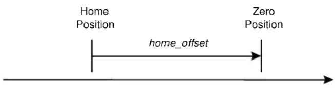
Fig. 8.2: Home Offset
| Index | 607C_h |
| Name | home_offset |
| Object code | VAR |
| Data Type | INT32 |
| Access | rw |
| PDO Mapping | yes |
| Units | position units |
| Value Range | -- |
| Default Value | 0 |
Object 6098 _h : homing\_method
A series of different methods are provided for a homing run. Through the object homing_method, the variant needed for the application can be selected. There are four possible homing run signals: the negative and positive limit switch, the homing switch and the (periodic) zero pulse of the angle encoder. In addition, the motor controller can reference itself to the negative or positive stop completely without an additional signal. When a referencing method is determined via the object homing_method, the following settings are made:
- the homing source (neg./pos. limit switch, the homing switch, neg./pos. stop)
- the direction and process of the homing run
- the type of evaluation of the zero pulse from the angle encoder used.
8. Operating modes
| Index | 6098_h |
| Name | homing_method |
| Object code | VAR |
| Data Type | INT8 |
| Access | rw |
| PDO Mapping | yes |
| Units | |
| Value Range | -18, -17, -2, -1, 1, 2, 7, 11, 17, 18, 23, 27, 32, 33, 34, 35 |
| Default Value | 17 |
| Value | Direction | Objective | Reference point for zero |
| -18 | positive | Stop | Stop |
| -17 | negative | Stop | Stop |
| -2 | positive | Stop | Zero pulse |
| -1 | negative | Stop | Zero pulse |
| 1 | negative | Limit switch | Zero pulse |
| 2 | positive | Limit switch | Zero pulse |
| 7 | positive | Homing switch | Zero pulse |
| 11 | negative | Homing switch | Zero pulse |
| 17 | negative | Limit switch | Limit switch |
| 18 | positive | Limit switch | Limit switch |
| 23 | positive | Homing switch | Homing switch |
| 27 | negative | Homing switch | Homing switch |
| 33 | negative | Zero pulse | Zero pulse |
| 34 | positive | Zero pulse | Zero pulse |
| 35 | No travel | Current actual position |
The homing_method can only be set when the reference travel is not active. Otherwise, an error message (see chapter 5.5) is returned.
The process of the individual methods is described in detail in chapter 0.
8. Operating modes
Object 6099 _h : homing speeds
This object determines the speeds used during the homing run.
| Index | 6099_h |
| Name | homing speeds |
| Object code | ARRAY |
| No. of Elements | 2 |
| Data Type | UINT32 |
| Sub-index | 01_h |
| Description | speed_during_search_for_switch |
| Access | rw |
| PDO Mapping | yes |
| Units | speed units |
| Value Range | -- |
| Default Value | 100 min^-1 |
| Sub-index | 02_n |
| Description | speed_during_search_for_zero |
| Access | rw |
| PDO Mapping | yes |
| Units | speed units |
| Value Range | -- |
| Default Value | 10 min^-1 |

If bit 6 is set in the object compatibility_control (see chapter 6.2), a run to zero follows the homing run.
If this bit is set and the object speed_during_search_for_switch is written, both the velocity for the switch search and the velocity for the run to zero are written.
8. Operating modes
Object 609A _h : homing\_acceleration
The object homing_acceleration determines the acceleration that is used during the reference travel for all acceleration and braking processes.
| Index | 609A_h |
| Name | homing_acceleration |
| Object code | VAR |
| Data Type | UINT32 |
| Access | rw |
| PDO Mapping | yes |
| Units | acceleration units |
| Value Range | -- |
| Default Value | 1000 min^-1/s |
Object 2045 _h : homing\_timeout
The homing run can be monitored for its maximum execution time. The maximum execution time can be specified with the object homing_timeout. If this time is exceeded without the homing run being ended, error 11-3 is triggered.
| Index | 2045_h |
| Name | homing_timeout |
| Object code | VAR |
| Data Type | UINT16 |
| Access | rw |
| PDO Mapping | no |
| Units | ms |
| Value Range | 0 (off), 1 ... 65535 |
| Default Value | 60000 |
- Operating modes
8.2.3 Reference Travel Processes
The various homing run methods are depicted in the following illustrations. The circled numbers correspond to the code to be entered in the object homing_method.
Method 1: Negative limit switch with zero pulse evaluation
With this method, the drive first moves relatively quickly in a negative direction until it reaches the negative limit switch. This is depicted in the diagram through the rising edge. After that, the drive moves back slowly and searches for the exact position of the limit switch. The zero position refers to the first zero pulse of the angle transmitter in the positive direction from the limit switch.
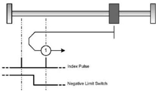
flowchart
graph TD
    A["Terminal Block"] --> B["Switch 1"]
    B --> C["Index Pulse"]
    B --> D["Negative Limit Switch"]
Fig. 8.3: Reference travel to the negative limit switch with evaluation of the zero pulse
Method 2: Positive limit switch with zero pulse evaluation
With this method, the drive first moves relatively quickly in a positive direction until it reaches the positive limit switch. This is depicted in the diagram through the rising edge. After that, the drive moves back slowly and searches for the exact position of the limit switch. The zero position refers to the first zero pulse of the angle transmitter in the negative direction from the limit switch.

Fig. 8.4: Reference travel to the positive limit switch with evaluation of the zero pulse
8. Operating modes
Methods 7 and 11: Homing switch and zero impulse evaluation
These two methods use the homing switch that is active over only a part of the section. These homing methods are especially useful for round-axis applications, where the homing switch is activated once per revolution.
With method 7, the drive first moves in a positive direction and with method 11 in a negative direction. Depending on the direction of travel, the zero position refers to the first zero pulse in the negative or positive direction from the homing switch. This can be seen in the two following depictions.
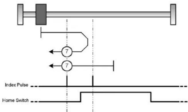
Fig. 8.5: Homing run to the homing switch with evaluation of the zero pulse with positive initial movement

For homing runs to the homing switch, the limit switches first serve to reverse the search direction. If the opposite limit switch is then reached, an error is triggered.

flowchart
graph TD
    A["Input"] --> B["11"]
    B --> C["11"]
    C --> D["Output"]
    E["Index Pulse"] --> F["Home Switch"]
    G["Ground"] --> H["Ground"]
Fig. 8.6: Homing run to the homing switch with evaluation of the zero pulse with negative initial movement
- Operating modes
Method 17: Reference travel to the negative limit switch
With this method, the drive first moves relatively quickly in a negative direction until it reaches the negative limit switch. This is depicted in the diagram through the rising edge. After that, the drive moves back slowly and searches for the exact position of the limit switch. The zero position refers to the falling edge from the negative limit switch.

Fig. 8.7: Reference travel to the negative limit switch
Method 18: Reference travel to the positive limit switch
With this method, the drive first moves relatively quickly in a positive direction until it reaches the positive limit switch. This is depicted in the diagram through the rising edge. After that, the drive moves back slowly and searches for the exact position of the limit switch. The zero position refers to the falling edge from the positive limit switch.

Fig. 8.8: Reference travel to the positive limit switch
8. Operating modes
Methods 23 and 27: Homing run to the homing switch
These two methods use the homing switch that is active over only a part of the section. This homing method is especially useful for round-axis applications, where the homing switch is activated once per revolution.
With method 23, the drive first moves in a positive direction and with method 27 a negative direction. The zero position refers to the falling edge from the homing switch. This can be seen in the two following depictions.

Fig. 8.9: Homing run to the homing switch with positive initial movement

For homing runs to the homing switch, the limit switches first serve to reverse the search direction. If the opposite limit switch is then reached, an error is triggered.

Fig. 8.10: Homing run to the homing switch with negative initial movement
8. Operating modes
Method -1: Negative stop with zero pulse evaluation
With this method, the drive first moves in a negative direction until it reaches the stop. The I²t integral of the motor rises hereby to a maximum 90 %. The stop must be mechanically dimensioned so that it does not suffer damage in the parameterised maximum current. The zero position refers to the first zero pulse of the angle transmitter in the positive direction from the stop.

Fig. 8.11: Reference travel to the negative stop with evaluation of the zero pulse
Method -2: Positive stop with zero pulse evaluation
With this method, the drive first moves in a positive direction until it reaches the stop. The I^2t integral of the motor rises hereby to a maximum 90 %. The stop must be mechanically dimensioned so that it does not suffer damage in the parameterised maximum current. The zero position refers to the first zero pulse of the angle transmitter in the negative direction from the stop.

Fig. 8.12: Reference travel to the positive stop with evaluation of the zero pulse
Method -17: Reference travel to the negative stop
With this method, the drive first moves in a negative direction until it reaches the stop. The I^2t integral of the motor rises hereby to a maximum 90 %. The stop must be mechanically dimensioned so that it does not suffer damage in the parameterised maximum current. The zero position refers directly to the stop.

Fig. 8.13: Reference travel to the negative stop
8. Operating modes
Method -18: Reference travel to the positive stop
With this method, the drive first moves in a positive direction until it reaches the stop. The I^2t integral of the motor rises hereby to a maximum 90 %. The stop must be mechanically dimensioned so that it does not suffer damage in the parameterised maximum current. The zero position refers directly to the stop.

natural_image
Pure mechanical diagram showing a shaft with two plates and a pressure gauge labeled -18 (no text or symbols beyond basic labels)Fig. 8.14: Reference travel to the positive stop
Methods 33 and 34: Reference travel to the zero pulse
The zero position refers to the first zero pulse of the angle transmitter in the direction of search.

Fig. 8.15: Reference travel only with reference to the zero pulse
Method 35: Reference travel to the current position
With method 35, the zero position refers to the current position.
If the drive should not be newly referenced but only the position set to a specified value, the object 2030_h (set_position_absolute) can be used. See chapter 6.7.2.
8.2.4 Control of Reference Travel
Reference travel is controlled and monitored through the controlword/statusword. The start is made by setting bit 4 in the controlword. The successful completion of the travel is shown by a set bit 12 in the object statusword. A set bit 13 in the object statusword shows that an error has occurred during the reference travel. The cause of the error can be determined via the objects error_register and pre_defined_error_field.
| Bit 4 | Meaning |
| 0 | Homing run is not active |
| 0 → | Start homing |
| 1 | Homing run is active |
| 1 →0 | Homing run interrupted |
Tab. 8.1: Description of the bits in the controlword
8. Operating modes
| Bit 13 | Bit 12 | Meaning |
| 0 | 0 | Homing run is not completed yet |
| 0 | 1 | Homing run successfully completed |
| 1 | 0 | Homing run not successfully completed |
| 1 | 1 | Prohibited condition |
Tab. 8.2: Description of the bits in the statusword
8.3 Positioning Operating Mode (Profile Position Mode)
8.3.1 Overview
The structure of this operating mode is evident in Fig. 8.16:
The target position (target_position) is passed on to the curve generator. This generates a nominal position value (position_demand_value) for the position controller, which is described in the Position Controller chapter (Position Control Function, chapter 0). These two function blocks can be set independently of each other.

flowchart
graph TD
    A["target_position 607Ah"] --> B["Trajectory Generator"]
    C["trajectory Generator Parameters"] --> B
    D["position Control Law Parameters"] --> E["Position Control Function"]
    B --> E
    E --> F["control_effort (60FAh)"]
    G["target_position (607Ah)"] --> H["[position units"]]
    H --> I["Limit Function"]
    I --> J["Multiplier"]
    J --> K["position"]
    I --> L["position_range_limit (607Bh)<br>software_position_limit (607Dh)<br>home_offset (607Ch)"]
    J --> M["position_factor (6093h)<br>polarity (607Eh)"]
Fig. 8.16: Curve generator and position controller
All input variables of the curve generator are converted with the variables of the factor group (see chapter 6.3) into the internal units of the regulator. The internal variables are marked here with an asterisk and are normally not needed by the user.
8.3.2 Description of the Objects
Objects treated in this chapter
| Index | Object | Name | Type | Attr. |
| 607A_h | VAR | target_position | INT32 | rw |
| 6081_h | VAR | profile_velocity | UINT32 | rw |
| 6082_h | VAR | end_velocity | UINT32 | rw |
| 6083_h | VAR | profile_acceleration | UINT32 | rw |
| 6084_h | VAR | profile_deceleration | UINT32 | rw |
| 6085_h | VAR | quick_stop_deceleration | UINT32 | rw |
| 6086_h | VAR | motion_profile_type | INT16 | rw |
Affected objects from other chapters
| Index | Object | Name | Type | Chapter |
| 6040_h | VAR | controlword | INT16 | 7.1.3 Controlword (control word) |
| 6041_h | VAR | statusword | UINT16 | 7.1.5 Statuswords (status word) |
| 605A_h | VAR | quick_stop_option_code | INT16 | 7 Device control |
| 607E_h | VAR | polarity | UINT8 | 6.3 Conversion factors |
| 6093_h | ARRAY | position_factor | UINT32 | 6.3 Conversion factors |
| 6094_h | ARRAY | velocity_encoder_factor | UINT32 | 6.3 Conversion factors |
| 6097_h | ARRAY | acceleration_factor | UINT32 | 6.3 Conversion factors |
Object 607A _h : target\_position
The object target_position (target position) determines to which position the motor controller should travel. The current setting for speed, acceleration, brake delay and type of travel profile (motion_profile_type) etc. must be considered thereby. The target position (target_position) is interpreted either as an absolute or relative statement (controlword, bit 6).
| Index | 607A_h |
| Name | target_position |
| Object code | VAR |
| Data Type | INT32 |
| Access | rw |
| PDO Mapping | yes |
| Units | position units |
| Value Range | -- |
| Default Value | 0 |
8. Operating modes
Object 6081h: profile\_velocity
The object profile_velocity specifies the speed that is normally reached at the end of the acceleration ramp during positioning. The object profile_velocity is specified in speed units.
| Index | 6081_h |
| Name | profile_velocity |
| Object code | VAR |
| Data Type | UINT32 |
| Access | rw |
| PDO Mapping | yes |
| Units | speed_units |
| Value Range | -- |
| Default Value | 1000 |
Object 6082 _h : end\_velocity
The object end_velocity (end speed) defines the speed the drive must have when it reaches the target position (target_position). Normally, this object must be set to zero so that the motor controller stops when it reaches the target position (target_position). For continuous positioning, a speed different from zero can be specified. The object end_velocity is specified in the same units as the object profile_velocity.
| Index | 6082_h |
| Name | end_velocity |
| Object code | VAR |
| Data Type | UINT32 |
| Access | rw |
| PDO Mapping | yes |
| Units | speed units |
| Value Range | -- |
| Default Value | 0 |
8. Operating modes
Object 6083 _h : profile\_acceleration
The object profile_acceleration specifies the acceleration with which the motor accelerates to the nominal value. It is specified in user-defined acceleration units, (see chapter 6.3, Factor Group).
| Index | 6083_h |
| Name | profile_acceleration |
| Object code | VAR |
| Data Type | UINT32 |
| Access | rw |
| PDO Mapping | yes |
| Units | acceleration units |
| Value Range | -- |
| Default Value | 10000 min^-1/s |
Object 6084 _h : profile\_deceleration
The object profile_deceleration specifies the deceleration with which the motor is braked. It is specified in user-defined acceleration units, (see chapter 6.3, Factor Group).
| Index | 6084h |
| Name | profile_deceleration |
| Object code | VAR |
| Data Type | UINT32 |
| Access | rw |
| PDO Mapping | yes |
| Units | acceleration units |
| Value Range | -- |
| Default Value | 10000 min^-1/s |
Object 6085h: quick\_stop\_deceleration
The object quick_stop_deceleration specifies with which brake delay the motor stops when a quick stop is carried out (see chapter 0). The object quick_stop_deceleration is specified in the same unit as the object profile_deceleration.
| Index | 6085_h |
| Name | quick_stop_deceleration |
| Object code | VAR |
| Data Type | UINT32 |
8. Operating modes
| Access | rw |
| PDO Mapping | yes |
| Units | acceleration units |
| Value Range | -- |
| Default Value | 14100 min^-1/s |
Object 6086 _h : motion\_profile\_type
The object motion_profile_type is used to select the type of positioning profile. The object motion_profile_type.
| Index | 6086_h |
| Name | motion_profile_type |
| Object code | VAR |
| Data Type | INT16 |
| Access | rw |
| PDO Mapping | yes |
| Units | -- |
| Value Range | 0, 2 |
| Default Value | 0 |
| Value | Curve chape |
| 0 | Linear ramp |
| 2 | Jerk-free ramp |
8.3.3 Functional description
There are two possibilities for passing on a target position to the motor controller:
Simple positioning task
If the motor controller has reached a target position, it signals this to the host with the bit target_reached (bit 10 in the object statusword). In this operating mode, the motor controller stops when it has reached the goal.
Sequence of positioning tasks
After the motor controller has reached a target, it immediately begins travelling to the next target. This transition can occur smoothly, without the motor controller meanwhile coming to a standstill.
These two methods are controlled through the bits new_set_point and change_set_immediately in the object controlword and set_point_acknowledge in the object statusword. These bits are in a question-answer relationship to each other. This makes it possible to prepare a positioning task while another is still running.
8. Operating modes

Fig. 8.17: Positioning task transmittal from a host
In Fig. 8.17, you can see how the host and the motor controller communicate with each other via the CAN bus:
First, the positioning data (target position, travel speed, end speed and acceleration) are transmitted to the motor controller. When the positioning data set has been completely written (1), the host can start positioning by setting the bit new_set_point in the controlword to "1" (2). After the motor controller recognises the new data and takes it over into its buffer, it reports this to the host by setting the bit set_point_acknowledge in the statusword (3).
Then the host can begin to write a new positioning data set into the motor controller (4) and delete the bit new_set_point again (5). Only when the motor controller can accept a new positioning task (6) does it signal this through a "0" in the set_point_acknowledge bit. Before this, no new positioning may be started by the host (7).
In Fig. 8.18, a new positioning task is only started after the previous one has been completely finished. To determine this, the host evaluates the target_reached bit in the object statusword.
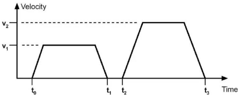
line
| Time | Velocity | |------|----------| | t₀ | V₁ | | t₁ | V₁ | | t₂ | V₂ | | t₃ | V₂ |Fig. 8.18: Simple positioning task
8. Operating modes
In Fig. 8.19, a new positioning task is already started while the previous one is still in process. The host already passes the subsequent target on to the motor controller when the motor controller signals with deletion of the bit set_point_acknowledge that it has read the buffer and started the related positioning. In this way, positioning tasks follow each other seamlessly. For this operating mode, the object end_velocity should be written with the same value as the object profile_velocity so that the motor controller does not briefly brake to zero each time between the individual positioning tasks.
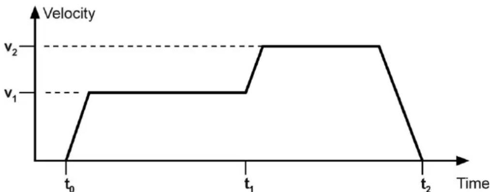
line
| Time | Velocity | |------|----------| | t₀ | v₁ | | t₁ | v₂ | | t₂ | v₂ |Fig. 8.19: Continuous sequence of positioning tasks
If besides the bit new_set_point the bit change_set_immediately is also set to "1" in the controlword, the host instructs the motor controller to start the new positioning task immediately. In this case, a positioning task already in process is interrupted.
8.4 Interpolated position mode
8.4.1 Overview
The interpolated position mode (IP) permits specification of nominal position values in a - multi-axis use of the motor controller. To do this, synchronisation telegrams (SYNC) and nominal position values are specified by a higher-level controller in a fixed time grid - (synchronisation interval). Since the interval is normally greater than one position controller cycle, the motor controller independently interpolates the data values between two specified position values, as shown in the following diagram.
8. Operating modes

line
| t | Position Demand Value | | --- | --- | | Start | High | | Midpoint | Medium | | End | Low |Fig. 8.20: Positioning task linear interpolation between two data values
In the following, the objects needed for the interpolated position mode are described first. A subsequent functional description comprehensively covers the activation and sequencing of parameter setting.
8.4.2 Description of the Objects
Objects treated in this chapter
| Index | Object | Name | Type | Attr. |
| 60C0_h | VAR | interpolation_submode_select | INT16 | rw |
| 60C1_h | REC | interpolation_data_record | rw | |
| 60C2_h | REC | interpolation_time_period | rw | |
| 60C3_h | ARRAY | interpolation_sync_definition | UINT8 | rw |
| 60C4_h | REC | interpolation_data_configuration | rw |
Affected objects from other chapters
| Index | Object | Name | Type | Chapter |
| 6040_h | VAR | controlword | INT16 | 7.1.3 Controlword (control word) |
| 6041_h | VAR | statusword | UINT16 | 7.1.5 Statuswords (status word) |
8. Operating modes
| Index | Object | Name | Type | Chapter |
| 6093_h | ARRAY | position_factor | UINT32 | 6.3 Conversion factors |
| 6094_h | ARRAY | velocity_encoder_factor | UINT32 | 6.3 Conversion factors |
| 6097_h | ARRAY | acceleration_factor | UINT32 | 6.3 Conversion factors |
Object 60C0h: interpolation\_submode\_select
The type of interpolation is established via the object interpolation_submode_select. Currently, only the manufacturer-specific variant "Linear Interpolation without Buffer" is available.
| Index | 60CO_h |
| Name | interpolation_submode_select |
| Object code | VAR |
| Data Type | INT16 |
| Access | rw |
| PDO Mapping | yes |
| Units | -- |
| Value Range | -2 |
| Default Value | -2 |
| Value | Interpolation type |
| -2 | Linear Interpolation without Buffer |
Object 60C1h: interpolation\_data\_record
The object record interpolation_data_record represents the actual data record. It consists of an entry for the position value (ip_data_position) and a control word (ip_data_controlword), which specifies whether the position value should be interpreted absolutely or relatively. Specification of the control word is optional. If it is not specified, the position value is interpreted absolutely. If the control word should also be specified, for reasons of data consistency, first subindex 2 (ip_data_controlword) and then subindex 1 (ip_data_position) are written, since data transfer is triggered internally with write access to ip_data_position.
| Index | 60C1h |
| Name | interpolation_data_record |
| Object code | RECORD |
| No. of Elements | 2 |
8. Operating modes
| Sub-index | 01_h |
| Description | ip_data_position |
| Data Type | INT32 |
| Access | rw |
| PDO Mapping | yes |
| Units | position units |
| Value Range | -- |
| Default Value | -- |
| Sub-index | 02_h |
| Description | ip_data_controlword |
| Data Type | UINT8 |
| Access | rw |
| PDO Mapping | yes |
| Units | -- |
| Value Range | 0, 1 |
| Default Value | 0 |
| Value | ip_data_position actual |
| 0 | Absolute position |
| 1 | Relative distance |

The internal data transfer takes place with write access to subindex 1. If subindex 2 should also be used, it must be written before subindex 1.
Object 60C2h: interpolation\_time\_period
The synchronisation interval can be set via the object record interpolation_time_period. Via ip_time_index, the unit (ms or 1/10 ms) of the interval is established, which is parameterised via ip_time_units. To achieve synchronisation, the complete controller cascade (current, speed and position controller) is synchronised up to the external cycle. A change in the synchronisation interval is therefore effective only after a reset. Therefore, if the interpolation interval is to be changed via the CAN bus, the parameter set must be saved (see chapter 6.1) and a reset performed (see chapter 5.6) so that the new synchronisation interval becomes effective. The synchronisation interval must be maintained exactly.
8. Operating modes
| Index | 60C2h |
| Name | interpolation_time_period |
| Object code | RECORD |
| No. of Elements | 2 |
| Sub-index | 01_h |
| Description | ip_time_units |
| Data Type | UINT8 |
| Access | rw |
| PDO Mapping | yes |
| Units | according to ip_time_index |
| Value Range | ip_time_index = -3: 1, 2 ... 9, 10ip_time_index = -4: 10, 20 ... 90, 100 |
| Default Value | -- |
| Sub-index | 02_h |
| Description | ip_time_index |
| Data Type | INT8 |
| Access | rw |
| PDO Mapping | yes |
| Units | -- |
| Value Range | -3, -4 |
| Default Value | -3 |
| Value | ip_time_units is specified in |
| -3 | 10^3 seconds (ms) |
| -4 | 10^4 seconds (0.1 ms) |

A change in the synchronisation interval is effective only after a reset. If the interpolation interval is to be changed via the CAN bus, the parameter set must be saved and a reset performed.
8. Operating modes
Object 60C3h: interpolation\_sync\_definition
The object interpolation_sync_definition sets the type (synchronize_on_group) and number of (ip_sync_every_n_event) of synchronisation telegrams per synchronisation interval. For the CMMP series, only the standard SYNC telegram and 1 SYNC per interval can be set.
| Index | 60C3_h |
| Name | interpolation_sync_definition |
| Object code | ARRAY |
| No. of Elements | 2 |
| Data Type | UINT8 |
| Sub-index | 01_h |
| Description | syncronize_on_group |
| Access | rw |
| PDO Mapping | yes |
| Units | -- |
| Value Range | 0 |
| Default Value | 0 |
| Value | Meaning |
| 0 | use Standard SYNC telegram |
| Sub-index | 02_n |
| Description | ip_sync_every_n_event |
| Access | rw |
| PDO Mapping | yes |
| Units | -- |
| Value Range | 1 |
| Default Value | 1 |
Object 60C4h: interpolation\_data\_configuration
The object record interpolation_data_configuration can be used to configure the type (buffer_organisation) and size (max_buffer_size, actual_buffer_size) of any buffer present as well as access to it (buffer_position, buffer_clear). The size of a buffer element can be read out via the object size_of_data_record. Although no buffer is available for the interpolation type "Linear interpolation without buffer", access via the object buffer_clear must still be enabled in this case as well.
8. Operating modes
| Index | 60C4h |
| Name | interpolation_data_configuration |
| Object code | RECORD |
| No. of Elements | 6 |
| Sub-index | 01_h |
| Description | max_buffer_size |
| Data Type | UINT32 |
| Access | ro |
| PDO Mapping | no |
| Units | -- |
| Value Range | 0 |
| Default Value | 0 |
| Sub-index | 02_h |
| Description | actual_size |
| Data Type | UINT32 |
| Access | rw |
| PDO Mapping | yes |
| Units | -- |
| Value Range | 0 ... max_buffer_size |
| Default Value | 0 |
| Sub-index | 03_h |
| Description | buffer_organisation |
| Data Type | UINT8 |
| Access | rw |
| PDO Mapping | yes |
| Units | -- |
| Value Range | 0 |
| Default Value | 0 |
| Value | Meaning |
| 0 | FIFO |
8. Operating modes
| Sub-index | 04_h |
| Description | buffer_position |
| Data Type | UINT16 |
| Access | rw |
| PDO Mapping | yes |
| Units | -- |
| Value Range | 0 |
| Default Value | 0 |
| Sub-index | 05_h |
| Description | size_of_data_record |
| Data Type | UINT8 |
| Access | wo |
| PDO Mapping | yes |
| Units | -- |
| Value Range | 2 |
| Default Value | 2 |
| Sub-index | 06_h |
| Description | buffer_clear |
| Data Type | UINT8 |
| Access | wo |
| PDO Mapping | yes |
| Units | -- |
| Value Range | 0, 1 |
| Default Value | 0 |
| Value | Meaning |
| 0 | Delete buffer / access to 60C1h not permitted |
| 1 | Access to 60C1h enabled |
8.4.3 Functional description
Preparatory parameter setting
Before the motor controller can be switched into the operating mode interpolated position mode, various settings must be made: These include setting of the interpolation interval (interpolation_time_period), that is, the time between two SYNC telegrams, the interpolation type (interpolation_submode_select) and the type of synchronisation (interpolation_sync_definition). In addition, access to the position buffer must be activated via the object buffer_clear.
EXAMPLE
| Task | CAN-Objekt / COB |
| Type of -2 interpolation | 60C0h, interpolation_submode_select = -2 |
| Time unit 0.1 ms | 60C2h_02h, interpolation_time_index = -04 |
| Time interval 4 ms | 60C2h_01h, interpolation_time_units = 40 |
| Save parameters | 1010h_01h, save_all_parameters |
| Perform reset | NMT reset node |
| Waiting for bootup | Bootup message |
| Buffer activation 1 | 60C4h_06h, buffer_clear = 1 |
| Generate SYNC | SYNC (matrix 4 ms) |
Activation of the interpolated position mode and synchronisation
The IP is activated via the object modes_of_operation (6060h). Starting with this time, the motor controller tries to synchronise itself to the external time grid, which is specified through the SYNC telegrams. If the motor controller is able to synchronise itself, it reports the operating mode interpolated position mode in the object modes_of_operation_display (6061h). During synchronisation, the motor controller reports back invalid mode of operation (-1). If the SYNC-telegrams are not sent in the right time grid after completed synchronisation, the motor controller switches back into the invalid mode of operation.
If the mode of operation is taken up, transfer of position data to the drive can begin. As is logical, the higher-level controller first reads the current actual position out of the regulators and writes it cyclically into the motor controller as a new nominal value (interpolation_data_record). Takeover of data by the motor controller is activated via handshake bits of the controlword and statusword. By setting the bit enable_ip_mode in the controlword, the host shows that evaluation of the position data should begin. The data records are evaluated only when the motor controller acknowledges this via the status bit ip_mode_selected in the statusword.
In detail, therefore, the following assignment and procedure result:
8. Operating modes

other
| State | Value | |-------|-------| | modes_of_operation = 7 | 7 | | modes_of_operation_display = 7 | 7 | | controlword Bit 4: enable_ip_mode | - | | controlword Bit 12: ip_mode_active | - | | Position 0 | 0 | | Position 0 | 0 | | Position 0 | 0 | | Position 0 | 0 | | Position 1 | 1 | | Position 1 | 2 | | Position 3 | 3 | | Position 4 | 4 |Fig. 8.21: Synchronisation and data release
| No. | Event | CAN Object |
| 1 | Generate SYNC message | |
| 2 | Request of the ip operating mode | 6060_h , modes_of_operation = 07 |
| 3 | Wait until operating mode is taken | 6061_h , modes_of_operation_display = 07 |
| 4 | Reading out the current actual position | 6064_h , position_actual_value |
| 5 | Writing back as current nominal position | 60C1_h\_01_h , ip_data_position |
| 6 | Start of interpolation | 6040_h , controlword, enable_ip_mode |
| 7 | Acknowledgement by motor controller | 6041_h , statusword, ip_mode_active |
| 8 | Changing the current nominal position in accordance with trajectory | 60C1_h\_01_h , ip_data_position |
After the synchronous travel process is ended, deletion of the bit enable_ip_mode prevents further evaluation of position values. Then the system can switch into another operating mode, if necessary.
8. Operating modes
Interruptions of interpolation in case of error
If an ongoing interpolation type (ip_mode_active set) is interrupted by a controller error, the drive first acts as specified for the respective error (e.g. removal of the controller enable and change into the condition SWITCH_ON_DISABLED.
The interpolation can only be continued through a new synchronisation, since the motor controller must be brought back into the condition OPERATION_ENABLE, through which the bit ip_mode_active is deleted.
8.5 RPM Regulation Operating Mode (Profile Velocity Mode)
8.5.1 Overview
The speed-regulated operation (profile velocity mode) contains the following subfunctions:
- Nominal value generation through the ramp generator
- RPM recording through differentiation via the angle transmitter
- RPM regulation with appropriate input and output signals
- Limitation of the torque nominal value (torque_demand_value)
- Monitoring of the actual speed (velocity_actual_value) with the window function/threshold.
The significance of the following parameters is described in the Positioning chapter (Profile Position Mode): profile_acceleration, profile_deceleration, quick_stop.
8. Operating modes

flowchart
graph TD
    A["target_velocity (60FFh)"] --> B["Multiplier"]
    C["profile_acceleration (6083h)"] --> D["Multiplier"]
    E["profile_deceleration (6084h)"] --> D
    F["quick_stop_deceleration (6085h)"] --> D
    B --> G["Limit Function"]
    D --> G
    G --> H["Profile Velocity*"]
    G --> I["Profile Acceleration*"]
    G --> J["Profile Deceleration*"]
    G --> K["Quick Stop Deceleration*"]
    L["velocity_encoder_factor (6094h)"] --> B
    M["acceleration_factor (6097h)"] --> D
    N["velocity_demand_value (606Bh)"] --> H

flowchart
graph TD
    A["position_actual_value (6063h)"] --> B["Differentiation d/dt"]
    B --> C["velocity actual_value (606Ch)"]
    D["velocity_demand_value (606Bh)"] --> E["Velocity Controller"]
    F["velocity_control_parameter_set (60F9h)"] --> E
    E --> G["control effort"]
    H["velocity_treshold_time (6070h)"] --> I["Window Comparator"]
    J["velocity_actual_value (606Ch)"] --> I
    K["velocity_treshold (606Fh)"] --> I
    I --> L["Timer"]
    M["velocity_window_time (606Eh)"] --> N["Window Comparator"]
    O["velocity_actual_value (606Ch)"] --> N
    P["velocity_window (606Dh)"] --> N
    N --> Q["Timer"]
    R["status_word (6041h) velocity = 0"] --> L
    S["status_word (6041h) velocity_reached"] --> Q
Fig. 8.22: Structure of the speed-regulated operation (profile velocity mode)
8.5.2 Description of the Objects
Objects treated in this chapter
| Index | Object | Name | Type | Attr. |
| 6069_h | VAR | velocity_sensor_actual_value | INT32 | ro |
| 606A_h | VAR | sensor_selection_code | INT16 | rw |
| 606B_h | VAR | velocity_demand_value | INT32 | ro |
| 202E_h | VAR | velocity_demand_sync_value | INT32 | ro |
| 606C_h | VAR | velocity_actual_value | INT32 | ro |
| 606D_h | VAR | velocity_window | UINT16 | rw |
| 606E_h | VAR | velocity_window_time | UINT16 | rw |
| 606F_h | VAR | velocity_threshold | UINT16 | rw |
| 6080_h | VAR | max_motor_speed | UINT32 | rw |
| 60FF_h | VAR | target_velocity | INT32 | rw |
Affected objects from other chapters
| Index | Object | Name | Type | Chapter |
| 6040_h | VAR | controlword | INT16 | 7.1.3 Controlword (control word) |
| 6041_h | VAR | statusword | UINT16 | 7.1.5 Statuswords (status word) |
| 6063_h | VAR | position_actual_value* | INT32 | 6.7 Position controller |
| 6071_h | VAR | target_torque | INT16 | 8.7 Torque controller |
| 6072_h | VAR | max_torque_value | UINT16 | 8.7 Torque controller |
| 607E_h | VAR | polarity | UINT8 | 6.3 Conversion factors |
| 6083_h | VAR | profile_acceleration | UINT32 | 8.3 Positioning |
| 6084_h | VAR | profile_deceleration | UINT32 | 8.3 Positioning |
| 6085_h | VAR | quick_stop_deceleration | UINT32 | 8.3 Positioning |
| 6086_h | VAR | motion_profile_type | INT16 | 8.3 Positioning |
| 6094_h | ARRAY | velocity_encoder_factor | UINT32 | 6.3 Conversion factors |
8. Operating modes
Object 6069h: velocity\_sensor\_actual\_value
With the object velocity_sensor_actual_value, the value of a possible speed transmitter can be read out in internal units. A separate speed transmitter cannot be connected in the CMMP family. Therefore, to determine the actual speed value, the object 606C_h should be used.
| Index | 6069_h |
| Name | velocity_sensor_actual_value |
| Object code | VAR |
| Data Type | INT32 |
| Access | ro |
| PDO Mapping | yes |
| Units | R / 4096 min |
| Value Range | -- |
| Default Value | -- |
Object 606A _h : sensor\_selection\_code
The speed sensor can be selected with this object. Currently, no separate speed sensor is planned. Therefore, only the default angle encoder is accessible.
| Index | 606A_n |
| Name | sensor_selection_code |
| Object code | VAR |
| Data Type | INT16 |
| Access | rw |
| PDO Mapping | yes |
| Units | -- |
| Value Range | 0 |
| Default Value | 0 |
Object 606Bh: velocity\_demand\_value
The current nominal speed of the velocity controller can be read with this object. It is acted upon by the nominal value of the ramp and curve generators. If the position controller is activated, its correction speed is also added.
| Index | 606B_h |
| Name | velocity_demand_value |
| Object code | VAR |
| Data Type | INT32 |
8. Operating modes
| Access | ro |
| PDO Mapping | yes |
| Units | speed units |
| Value Range | -- |
| Default Value | -- |
Object 202E _h : velocity\_demand\_sync\_value
The command velocity of the synchronisation encoder can be read out via this object. This is defined by the object 2022_h synchronization_encoder_select (see chapter 6.11). This object is specified in user-defined increments.
| Index | 202E_h |
| Name | velocity_demand_sync_value |
| Object code | VAR |
| Data Type | INT32 |
| Access | ro |
| PDO Mapping | no |
| Units | velocity units |
| Value Range | -- |
| Default Value | -- |
Objekt 606C _h : velocity\_actual\_value
The actual speed value can be read via the object velocity_actual_value.
| Index | 606C_h |
| Name | velocity_actual_value |
| Object code | VAR |
| Data Type | INT32 |
| Access | ro |
| PDO Mapping | yes |
| Units | speed units |
| Value Range | -- |
| Default Value | -- |
8. Operating modes
Object 2074h: velocity\_actual\_value\_filtered
A filtered velocity feedback value can be read out via the object velocity_actual_value_filtered, but it can only be used for display purposes. In contrast to velocity_actual_value, velocity_actual_value_filtered is used not for control, but for turn-through protection of the controller. The filter time constant can be set via the object 2073 h (velocity_display_filter_time). See chapter 6.6.2, Object 2073 h .
| Index | 2074_h |
| Name | velocity_actual_value_filtered |
| Object code | VAR |
| Data Type | INT32 |
| Access | ro |
| PDO Mapping | yes |
| Units | speed units |
| Value Range | -- |
| Default Value | -- |
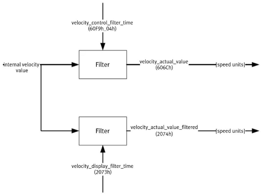
flowchart
graph TD
    A["velocity_control_filter_time (60F9h_04h)"] --> B["Filter"]
    C["internal velocity value"] --> B
    B --> D["velocity_actual_value (606Ch)"]
    D --> E["speed units"]
    B --> F["filter"]
    F --> G["velocity_actual_value_filtered (2074h)"]
    G --> H["speed units"]
    F --> I["velocity_display_filter_time (2073h)"]
Fig. 8.23: Determination of velocity_actual_value and velocity_actual_value_filtered
8. Operating modes
Object 606D _h : velocity\_window
The object velocity_window is used to set the window comparator. It compares the velocity feedback value with the specified final velocity (object 60FF_h : target_velocity). If the difference is a specific time period less than specified here, bit 10 target_reached in the object statusword is set.
See also: object 606E_h (velocity_window_time).
| Index | 606D_h |
| Name | velocity_window |
| Object code | VAR |
| Data Type | UINT16 |
| Access | rw |
| PDO Mapping | yes |
| Units | speed units |
| Value Range | 0 ... 65536 min^-1 |
| Default Value | 4 min^-1 |
Object 606E _h : velocity\_window\_time
The object velocity_window_time is used to set the window comparator along with the object 606Dh: velocity_window. The velocity must lie within the time specified here in the velocity_window so that bit 10 target_reached is set in the object statusword.
| Index | 606E_h |
| Name | velocity_window_time |
| Object code | VAR |
| Data Type | UINT16 |
| Access | rw |
| PDO Mapping | yes |
| Units | ms |
| Value Range | 0 ... 4999 |
| Default Value | 0 |
8. Operating modes
Object 606F _h : velocity\_threshold
The object velocity_threshold specifies from which velocity feedback value the drive is considered as standing still. If the drive exceeds the velocity value specified here for a certain period of time, bit 12 (velocity = 0) is deleted in the statusword. The time period is determined by the velocity_threshold_time.
| Index | 606F_h |
| Name | velocity_threshold |
| Object code | VAR |
| Data Type | UINT16 |
| Access | rw |
| PDO Mapping | yes |
| Units | speed units |
| Value Range | 0 ... 65536 min ^-1 |
| Default Value | 10 |
Object 6070 _h : velocity\_threshold\_time
The object velocity_threshold_time specifies how long the drive may exceed the specified velocity before bit 12 (velocity = 0) is deleted in the statusword.
| Index | 6070_h |
| Name | velocity_threshold_time |
| Object code | VAR |
| Data Type | UINT16 |
| Access | rw |
| PDO Mapping | yes |
| Units | ms |
| Value Range | 0 ... 4999 |
| Default Value | 0 |
Object 6080h: max\_motor\_speed
The object max_motor_speed specifies the maximum permitted velocity for the motor in min ^-1 . The object is used to protect the motor and can be taken from the motor datasheet. The velocity command value is limited to this value.
| Index | 6080_n |
| Name | max_motor_speed |
| Object code | VAR |
| Data Type | UINT16 |
8. Operating modes
| Access | rw |
| PDO Mapping | yes |
| Units | min^-1 |
| Value Range | 0 ... 32768 min^-1 |
| Default Value | 32768 min^-1 |
Objekt 60FF _h : target\_velocity
The object target_velocity is the nominal value specification for the ramp generator.
| Index | 60FF _h |
| Name | target_velocity |
| Object code | VAR |
| Data Type | INT32 |
| Access | rw |
| PDO Mapping | yes |
| Units | speed units |
| Value Range | -- |
| Default Value | -- |
8.6 Velocity ramps
If profile_velocity_mode is selected as modes_of_operation, the command value ramp is also activated. It is thus possible, via the objects profile_acceleration and profile_deceleration, to limit a jump-shaped command value change to a certain velocity - change per time. The controller makes it possible to not just specify different velocity changes for braking and acceleration, but also to differentiate between positive and negative velocity. The following illustration clarifies this behaviour:

line
| Time Period | Description | | ------------------------ |--------------------------------------------------| | Start | V (IN) | | Peak | OUT (OUT) | | Mid-2090 | 2090_02 velocity_acceleration_pos | | Mid-3090 | 2090_03 velocity_deceleration_pos | | Mid-4090 | 2090_04 velocity_acceleration_neg | | Mid-5090 | 2090_05 velocity_deceleration_neg |Fig. 8.24: Velocity ramps
8. Operating modes
The object group velocity_ramps exists so these 4 accelerations can be individually parameterised. Care should be taken that the objects profile_acceleration and profile_deceleration change the same internal accelerations as the velocity_ramps. If the profile_acceleration is written, velocity_acceleration_pos and velocity_acceleration_neg are changed together; if the profile_deceleration is written, velocity_deceleration_pos and velocity_deceleration_neg are changed together. Object velocity_ramps_enable determines whether or not the command values are led over the ramp generator.
| Index | 2090_h |
| Name | velocity_ramps |
| Object code | RECORD |
| No. of Elements | 5 |
| Sub-index | 01_h |
| Description | velocity_ramps_enable |
| Data Type | UINT8 |
| Access | rw |
| PDO Mapping | no |
| Units | .. |
| Value Range | 0: Command value NOT over the ramp generator1: Command value over the ramp generator |
| Default Value | 1 |
| Sub-index | 02_h |
| Description | velocity_acceleration_pos |
| Data Type | INT32 |
| Access | rw |
| PDO Mapping | no |
| Units | acceleration units |
| Value Range | .. |
| Default Value | 14100 min-1/s |
| Sub-index | 03_h |
| Description | velocity_deceleration_pos |
| Data Type | INT32 |
| Access | rw |
| PDO Mapping | no |
| Units | acceleration units |
| Value Range | .. |
| Default Value | 14100 min-1/s |
8. Operating modes
| Sub-index | 04_h |
| Description | velocity_acceleration_neg |
| Data Type | INT32 |
| Access | rw |
| PDO Mapping | no |
| Units | acceleration units |
| Value Range | .. |
| Default Value | 14100 min^-1/s |
| Sub-index | 05_h |
| Description | velocity_deceleration_neg |
| Data Type | INT32 |
| Access | rw |
| PDO Mapping | no |
| Units | acceleration units |
| Value Range | -- |
| Default Value | 14100 min^-1/s |
8.7 Torque Regulation Operating Mode (Profile Torque Mode)
8.7.1 Overview
This chapter describes torque-controlled operation. This operating mode allows an external torque nominal value target_torque, which can be smoothed using the integrated ramp generator, to be specified for the motor controller. It is thus possible for this motor controller to also be used for path control, with which both the position controller and the velocity controller are displaced to an external computer.

flowchart
graph LR
    A["target_torque (6071h)"] --> B["Limit Function"]
    C["motor_rated_torque (6076h)"] --> B
    D["torque_slope (6087h)"] --> E["Trajectory Generator"]
    F["torque_profile_type (6088h)"] --> E
    G["controlword (6040h)"] --> E
    B --> E
    E --> H["control_effort"]

    I["motor_rated_torque (6076h)"] --> J["Limit Function"]
    K["max_torque (6072h)"] --> J
    L["motor_rated_current (6075h)"] --> M["Limit Function"]
    N["max_current (6073h)"] --> M
    J --> N
    M --> O["Torque Control and Power Stage"]
    P["control_effort"] --> O
    Q["_torque_control_parameters (60F8h)"] --> O
    R["_power_stage_parameters (60F7h)"] --> O
    S["_motor_parameters (60F9h)"] --> O
    O --> T["Motor"]

    U["torque_demand (6074h)"] --> V["Motor"]
    W["torque_actual_value (6077h)"] --> V
    X["current_actual_value (6078h)"] --> V
    Y["DC_link_voltage (6079h)"] --> V
Fig. 8.25: Structure of torque-regulated operation
8. Operating modes
The parameters ramp steepness torque_slope and ramp shape torque_profile_type must be specified for the ramp generator.
If bit 8 Halt is set in the controlword, the ramp generator falls down to zero. It rises correspondingly again to the nominal torque target_torque when bit 8 is deleted again. In both cases, the ramp generator takes into account the ramp steepness torque_slope and the ramp shape torque_profile_type.
All definitions within this document refer to rotatable motors. If linear motors have to be used, all "torque" objects must refer to a "force" instead. For simplicity, the objects do not appear twice and their names should not be changed.
The operating modes positioning mode (profile position mode) and velocity controller (profile velocity mode) need the torque controller to work. That is why it is always necessary to set its parameters.
8.7.2 Description of the Objects
Objects treated in this chapter
| Index | Object | Name | Type | Attr. |
| 6071_h | VAR | target_torque | INT16 | rw |
| 6072_h | VAR | max_torque | UINT16 | rw |
| 6074_h | VAR | torque_demand_value | INT16 | ro |
| 6076_h | VAR | motor_rated_torque | UINT32 | rw |
| 6077_h | VAR | torque_actual_value | INT16 | ro |
| 6078_h | VAR | current_actual_value | INT16 | ro |
| 6079_h | VAR | DC_link_circuit_voltage | UINT32 | ro |
| 6087_h | VAR | torque_slope | UINT32 | rw |
| 6088_h | VAR | torque_profile_type | INT16 | rw |
| 60F7_h | RECORD | power_stage_parameters | rw | |
| 60F6_h | RECORD | torque_control_parameters | rw |
Affected objects from other chapters
| Index | Object | Name | Type | Chapter |
| 6040_h | VAR | controlword | INT16 | 7.1.3 Controlword (control word) |
| 60F9_h | RECORD | motor_parameters | 6.5 Current regulator and motor adjustment | |
| 6075_h | VAR | motor_rated_current | UINT32 | 6.5 Current regulator and motor adjustment |
| 6073_h | VAR | max_current | UINT16 | 6.5 Current regulator and motor adjustment |
8. Operating modes
Object 6071h: target\_torque
This parameter is the entry value for the torque regulator in torque-regulated mode (Profile Torque Mode). It is specified in thousandths of the nominal torque (object 6076 _h ).
| Index | 6071_h |
| Name | target_torque |
| Object code | VAR |
| Data Type | INT16 |
| Access | rw |
| PDO Mapping | yes |
| Units | motor_rated_torque / 1000 |
| Value Range | -32768 ... 32768 |
| Default Value | 0 |
This value represents the highest permissible torque of the motor. It is specified in thousandths of the nominal torque (object 6076 _h ). If, for example, a double overload of the motor is permissible for a short time, the value 2000 is entered here.

The Object 6072 h : max_torque corresponds with the object 6073 h : max_current and may only be written when the object 6075 _h : motor_rated_current was previously written with a valid value.
| Index | 6072_h |
| Name | max_torque |
| Object code | VAR |
| Data Type | UINT16 |
| Access | rw |
| PDO Mapping | yes |
| Units | motor_rated_torque / 1000 |
| Value Range | 1000 ... 65536 |
| Default Value | 2023 |
8. Operating modes
Object 6074h: torque\_demand\_value
By means of this object, the current nominal torque can be read out in thousands of the nominal torque (6076 _h ). The internal limitations of the controller (current limit values and I ^2 t monitoring) are hereby taken into account.
| Index | 6074_h |
| Name | torque_demand_value |
| Object code | VAR |
| Data Type | INT16 |
| Access | ro |
| PDO Mapping | yes |
| Units | motor_rated_torque / 1000 |
| Value Range | -- |
| Default Value | -- |
Object 6076 _h : motor\_rated\_torque
This object specifies the nominal torque of the motor. This can be taken from the motor's name plate. It is entered in the unit 0.001 Nm.
| Index | 6076_h |
| Name | motor_rated_torque |
| Object code | VAR |
| Data Type | UINT32 |
| Access | rw |
| PDO Mapping | yes |
| Units | 0.001 Nm |
| Value Range | -- |
| Default Value | 296 |
Object 6077h: torque\_actual\_value
By means of this object, the motor's actual torque can be read out in thousands of the nominal torque (object 6076 _h ).
| Index | 6077_h |
| Name | torque_actual_value |
| Object code | VAR |
| Data Type | INT16 |
8. Operating modes
| Access | ro |
| PDO Mapping | yes |
| Units | motor_rated_torque / 1000 |
| Value Range | -- |
| Default Value | -- |
Object 6078 _h : current\_actual\_value
By means of this object, the motor's actual torque can be read out in thousands of the nominal torque (object 6075 _h ).
| Index | 6078h |
| Name | current_actual_value |
| Object code | VAR |
| Data Type | INT16 |
| Access | ro |
| PDO Mapping | yes |
| Units | motor_rated_current / 1000 |
| Value Range | -- |
| Default Value | -- |
Object 6079h: dc\_link\_circuit\_voltage
The intermediate circuit voltage of the controller can be read out via this object. The voltage is specified in the unit millivolt.
| Index | 6079h |
| Name | dc_link_circuit_voltage |
| Object code | VAR |
| Data Type | UINT32 |
| Access | ro |
| PDO Mapping | yes |
| Units | mV |
| Value Range | -- |
| Default Value | -- |
8. Operating modes
Object 6087 _h : torque\_slope
This parameter describes the velocity change of the command value ramp. This is specified in thousandths of the nominal torque per second. For example, the torque-command value target_torque is raised from 0 Nm to the value motor_rated_torque. If the output value of the inserted torque ramp is to reach this value in one second, the value 1000 must be written in this object.
| Index | 6087h |
| Name | torque_slope |
| Object code | VAR |
| Data Type | UINT32 |
| Access | rw |
| PDO Mapping | yes |
| Units | motor_rated_torque / 1000 s |
| Value Range | -- |
| Default Value | E310F94_h |
Object 6088 _h : torque\_profile\_type
The object torque_profile_type specifies with which curve shape a command value jump should be carried out. Currently, only the linear ramp is implemented in this controller, so this object can only be written with the value 0.
| Index | 6088_h |
| Name | torque_profile_type |
| Object code | VAR |
| Data Type | INT16 |
| Access | rw |
| PDO Mapping | yes |
| Units | -- |
| Value Range | 0 |
| Default Value | 0 |
| Value | Meaning |
| 0 | Linear ramp |
9. Index
A
A in 7-segment display .... 130
Acceleration
Brake (positioning) 171
Quick stop (positioning) 171
With of the Reference travel ...... 161
acceleration_factor 65
Actual Intermediate circuit voltage ..... 73
Actual position value (position units) .. 93
Actual speed value 188
Actual torque value 198
Actual value
position in position_units (position_actual_value) 93
torque (torque_actual_value) ...... 198
actual_dc_link_circuit_voltage 73
actual_size 180
analog_input_offset 112
analog_input_offset_ch_0 112
analog_input_offset_ch_1 112
analog_input_offset_ch_2 112
analog_input_voltage 111
analog_input_voltage_ch_0 111
analog_input_voltage_ch_1 111
analog_input_voltage_ch_2 111
Analogue inputs 111
Input voltage channel 0 ...... 111
Input voltage channel 1 ...... 111
Input voltage channel 2 ...... 111
Input voltages 111
Offset voltages 112
Offset voltages channel 0 ...... 112
Offset voltages channel 1 ...... 112
Offset voltages channel 2 ...... 112
Angle transmitter offset 81
B
Brake
delay time 124
Brake delay time 124
brake_delay_time 124
buffer_clear 181
buffer_organisation 180
buffer_position 180
C
cob_id_sync 40
cob_id_used_by_pdo 34
commissioning_state 130
Condition
Not Ready to Switch On 137
Ready to Switch On 137
Switch On Disabled 137
Switched On 137
Contouring error 86
Definition 86
Error window 93
Timeout time 94
contouring error time-out time ..... 94
Contouring window 93
Control of the regulator 134
control_effort 94
Controller enable 69
Controller enable logic! 69
Controlword 139
Bit assignment 136, 140
Commands 140
Object description 139
Controlword for interpolation data .... 177
Conversion factors 59
Choice of algebraic sign 68
Position factor 61
Correction velocity 91
Current controller
Gain 83
Parameter 83
Time constant 84
Current limitation.... 98
Current nominal value 198
current_actual_value 199
current_limitation 98
Curve generator 168
Cycle time
Current controller 128
Position controller 129
Positioning control 129
Cycle time PDOs.... 34
cycletime_current_controller 128
cycletime_position_controller ...... 129
cycletime_trajectory_generator ...... 129
cycletime_velocity_controller ...... 129
D
dc_link_circuit_voltage 199
Default parameter values 56
Device control 134
Device nominal current 75
Device nominal voltage 72
dig_out_state_mapp_dout_1 115
dig_out_state_mapp_dout_2 ...... 115
dig_out_state_mapp_dout_3 ...... 116
Digital inputs 113
Digital outputs
Mapping of DOUT1 115
Mapping of DOUT2 115
Mapping of DOUT3 116
Digital outputs 114
Conditions 114
Mapping 115
Mask 114
digital_inputs 113
digital_outputs 114
digital_outputs_data 114
digital_outputs_mask 114
digital_outputs_state_mapping ..... 115
disable_operation_option_code ...... 152
Divisor
acceleration_factor 65
velocity_encoder_factor 63
drive_data ...... 69, 80, 95, 117, 123
E
EMERGENCY 42
EMERGENCY Message 42
Structure of the 42
Enable logic 70
enable_dc_link_undervoltage_error .... 74
enable_enhanced_modulation 70
enable_logic 69
encoder_emulation_data...... 106
encoder_emulation_offset 107
encoder_emulation_resolution.. 106, 107
encoder_offset_angle 81
encoder_x10_counter 105
encoder_x10_data_field 104
encoder_x10_divisor 105
encoder_x10_numerator 105
encoder_x10_resolution 104
encoder_x2a_data_field 102
encoder_x2a_divisor 102
encoder_x2a_numerator 102
encoder_x2a_resolution 102
encoder_x2b_counter 104
encoder_x2b_data_field 103
encoder_x2b_divisor 103
encoder_x2b_numerator 103
encoder_x2b_resolution 103
end_velocity 170
Error
Controller error 42
SDO error messages 28
Error management 132
Error register 42
error_management 132
Extended sinus modulation .... 70
F
Factor Group 59
acceleration_factor 65
polarity 68
velocity_encoder_factor 63
fault_reaction_option_code 153
Filter time constants synchronisation
speed 110
Final stage enable 69
Final stage parameters 69
device nominal current 75
device nominal voltage 72
enable logic 70
intermediate circuit voltage 73
max. Intermediate circuit voltage ..... 73
min. Intermediate circuit voltage ..... 74
PWM frequency 70
firmware_custom_version 127
firmware_main_version 127
first_mapped_object 35
Following error
limit value exceeded 96
following_error 86
following_error_time_out 94
following_error_window 93
fourth_mapped_object 36
G
Gain 83
H
home_offset 158
Homing Mode 156
homing mode home_offset 158
homing mode homing_acceleration .. 161
homing mode homing_method ...... 159
homing mode homing speeds ..... 160
Homing run
Timeout 161
homing_acceleration 161
homing_method 159
homing speeds 160
homing_switch_polarity 118
homing_switch_selector 119
homing_timeout 161
|
I^2t capacity utilisation ...... 79
l^2t time 79
Identification of the device 124
Identifier for PDO 34
identity_object 124
iit error trigger 80
iit_error_enable 80
iit_ratio_motor 79
iit_time_motor 79
Incremental encoder emulation
Offset...... 107
Resolution 106, 107
inhibit_time 34
Inputs, analogue 111
Intermediate circuit
Monitoring of the 74
Intermediate circuit monitoring ..... 73, 74
Intermediate circuit voltage
actual 73
maximum 73
minimal 74
Interpolation data 176
Interpolation type 176
interpolation_data_configuration ..... 179
interpolation_data_record 176
interpolation_submode_select ...... 176
interpolation_sync_definition 179
interpolation_time_period 178
ip_data_controlword 177
ip_data_position 177
ip_sync every n event 179
ip_time_index 178
ip_time_units.... 178
L
Limit switch 117, 162, 164
Limit switches
Emergency stop ramp 119
Polarity 117
Limit value contour error exceeded ..... 96
Limit value following error 95
limit_current 99,100
limit_current_input_channel 99
limit_speed_input_channel 100
limit_switch_deceleration 119
limit_switch_polarity 117
M
Manufacturer code 124
Mapping parameter for PDOs ...... 35
max_buffer_size 180
max_current 78
max_dc_link_circuit_voltage 73
max_motor_speed 191
max_position_range_limit 96
max_torque 197
Maximum current 75
Max. Intermediate circuit voltage ..... 73
Maximum Motor speed 191
Maximum torque 197
min_dc_link_circuit_voltage 74
min_position_range_limit 96
Min. Intermediate circuit voltage ..... 74
Mode of operation
Change of the 154
Read of the 155
Reference travel 156
modes_of_operation 154
modes_of_operation_display 155
motion_profile_type 172
Motor parameter
I^2t time 79
Nominal current 77
Number of pin(pairs) 78
Resolver offset angle 81
Motor peak current 78
motor_data 79,81
motor_rated_current 77
9. Index
motor_rated_torque 198
motor_temperature_sensor_polarity ... 82
N
Nominal current
motor 77
New travelling.... 173
Nominal motor current 77
Nominal speed for RPM regulation .... 192
Nominal torque (torque regulation) ... 197
Nominal value
Current 198
Synchronisation speed (velocity units) 188
Torque 197
nominal_current 75
nominal_dc_link_circuit_voltage ..... 72
Not Ready to Switch On 137
Number of Mapped Objects 35
Number of pin pairs 78
Number of pins 78
number_of_mapped_objects 35
Numerator
acceleration_factor 65
position_factor 61
velocity_encoder_factor 63
0
Objects
Object 1001 _h ...... 42
Object 1003_h 45
Object 1003_h-01_h 45
Object 1003_h-02_h 46
Object 1003_h - 03_h 46
Object 1003_h - 04_h 46
Object 1005_h 40
Object 1010_h 56
Object 1010_h-01_h 56
Object 1011 _h ....56
Object 1011 h –01 h ...... 56
Object 1018 _h .... 124
Object 1018 h –01 h ...... 124
Object 1018 h –03 h ...... 125
Object 1018 h -04 h ...... 125
Object 1401 _h ...... 39
Object 1402_h 39
Object 1403 _h .... 39
Object 1601 _h ....39
Object 1602_h 39
Object 1603 _h ...... 39
Object 1800_h 34,36
Object 1800_h - 01_h 34
Object 1800 h 02 h 34
Object 1800 h –03 h ...... 34
Object 1801_h 37
Object 1802_h 37
Object 1803_h 37
Object 1A00 _h ...... 35, 36
Object 1A00 h _00 h ...... 35
Object 1A00 h –01 h ...... 35
Object 1A00 h –02 h ...... 36
Object 1A00 h –03 h ...... 36
Object 1A00 h _04 h ...... 36
Object 1A01 _h ...... 37
Object 1A02 _h ...... 37
Object 1A03 _h ...... 37
Object 2014 _h ...... 38
Object 2015 _h ...... 38
Object 2016 _h ...... 38
Object 2017 _h ...... 38
Object 201A _n .... 106
Object 201A h –01 h ...... 106
Object 201A h _02 h ...... 107
Object 2021 _h ...... 108
Object 2022 _h ...... 109
Object 2023 _h ....110
Object 2024 _h ...... 102
Object 2024 h –01 h ...... 102
Object 2024 h –02 h ...... 102
Object 2024 h _03 h ...... 102
Object 2025 _h ....104
Object 2025 h –01 h ...... 104
Object 2025 h _02 h ...... 105
Object 2025 h –03 h ...... 105
Object 2025 h –04 h ...... 105
Object 2026 _h ....103
Object 2026 h –01 h ...... 103
Object 2026 h –02 h ...... 103
Object 2026 h –03 h ...... 103
Object 2026 h -04 h ..... 104
Object 2028 _h ...... 107
Object 202D _h ....92
Object 202E_h 188
Object 202F _h ....109
Object 202F h –07 h ....109
9. Index
Object 2045 _h ....161
Object 204A _h .... 120
Object 204A h –01 h ...... 120
Object 204A_h-02_h 121
Object 204A h –03 h ...... 121
Object 204A h –04 h ...... 122
Object 204A h –05 h ...... 122
Object 204A h –06 h ...... 122
Object 2090 _h ....193
Object 2090_h - 01_h 193
Object 2090 h –02 h ...... 193
Object 2090 h –03 h ...... 193
Object 2090 h –04 h ...... 194
Object 2090 h –05 h ...... 194
Object 2100 _h .... 132
Object 2400 _h .... 111
Object 2400h_01 _h ...... 111
Object 2400h_02 _h ...... 111
Object 2400 h –03 h ...... 111
Object 2401 _h .... 112
Object 2401_h - 01_h 112
Object 2401 h –02 h ...... 112
Object 2401 h –03 h ...... 112
Object 2415 _h ....98
Object 2415 h 01 h ....99
Object 2415 h 02 h ....99
Object 2416 _h .... 100
Object 2416_h-01_h 100
Object 2416_h - 02_h 100
Object 2420 _h .... 115
Object 2420_h - 01_h 115
Object 2420 h _02 h ...... 115
Object 2420 h –03 h ...... 116
Object 6040h 139
Object 6041 _h .... 143
Object 604D _h ....78
Object 605A _h ...... 152
Object 605B _h .... 151
Object 605C _h .... 152
Object 605E _h ....153
Object 6060 _h ....154
Object 6061 _h .... 155
Object 6062 _h ....92
Object 6064 _h ....93
Object 6065 _h ...... 93
Object 6066 _h ....94
Object 6067 _h ....94
Object 6068 _h ...... 95
Object 6069 _h ...... 187
Object 606A _n ...... 187
Object 606B _h ...... 187
Object 606C_h 188
Object 606D _h ...... 190
Object 606E_h 190
Object 606F _h ...... 191
Object 6070 _h ....191
Object 6071h 197
Object 6072 _h ...... 197
Object 6073 _h ....78
Object 6074 _h ...... 198
Object 6075 _h ....77
Object 6076 _h ...... 198
Object 6077 _h ....198
Object 6078_h 199
Object 6079 _h ...... 199
Object 607A _n ...... 169
Object 607B_h 96
Object 607Bh - 01h 96
Object 607Bh - 02h 96
Object 607C_h 158
Object 607E _h ...... 68
Object 6080 _h ...... 191
Object 6081 _h ...... 170
Object 6082_h 170
Object 6083 _h ....171
Object 6084 _h ...... 171
Object 6085 _h ...... 171
Object 6086 _h ...... 172
Object 6087 _h ...... 200
Object 6088 _h ...... 200
Object 6093 _h ....60
Object 6093 h _01 h ...... 61
Object 6093 h –02 h ...... 61
Object 6094 _h ...... 63
Object 6094 h –01 h ...... 63
Object 6094_h_02_h 63
Object 6097 _h ....65
Object 6097 h –01 h ...... 65
Object 6097 h –02 h ...... 65
Object 6098 _h ...... 159
Object 6099 _h ....160
Object 6099_h - 01_h 160
Object 6099 h –02 h ...... 160
Object 609A _n ...... 161
Object 60CO_h 176
Object 60C1h 176
Object 60C1 h –01 h ...... 177
Object 60C1h_02h 177
Object 60C2 _h ...... 178
Object 60C2 h –01 h ...... 178
Object 60C2 h –02 h ...... 178
Object 60C3 _h ....179
Object 60C3 h –01 h ...... 179
Object 60C3 h –02 h ...... 179
Object 60C4 _h ....179
Object 60C4 h –01 h ...... 180
Object 60C4 h –02 h ...... 180
Object 60C4h_03h 180
Object 60C4 h –04 h ...... 180
Object 60C4 h –05 h ...... 181
Object 60C4 h –06 h ...... 181
Object 60F6 _h 83
Object 60F6 h –01 h ......83
Object 60F6 h –02 h ...... 84
Object 60F9 _h 84
Object 60F9 h _01 h ....85
Object 60F9 h –02 h ......85
Object 60F9 h –04 h ......85
Object 60FA _h ...... 94
Object 60FB _h ...... 90
Object 60FB h –01 h ......90
Object 60FB h –02 h ....91
Object 60FB h –04 h ....91
Object 60FB h –05 h ....91
Object 60FD _h ....113
Object 60FE _h ....114
Object 60FE h -01 h .... 114
Object 60FEh - 02h 114
Object 60FF _h ...... 192
Object 6410 _h ....79,81
Object 6410_h - 03_h 79
Object 6410 h –04 h ...... 79
Object 6410_h - 10_h 80
Object 6410_h - 11_h 81
Object 6410_h - 11_h 81
Object 6410 h- 14 h 82
Object 6510_h ...... 69, 80, 95, 117, 123
Object 6510_h-10_h 69
Object 6510_h - 11_h 117
Object 6510_h - 13_h 119
Object 6510_h - 14_h 118
Object 6510 h —15 h .... 119
Object 6510 h –18 h ...... 124
Object 6510 h –20 h ...... 97
Object 6510 h 22 h ....95
Object 6510 h –30 h ...... 70
Object 6510 h –31 h ...... 71
Object 6510 h 33 h ....72
Object 6510 h –34 h ...... 73
Object 6510 h –35 h ...... 73
Object 6510 h 36 h ....74
Object 6510 h 37 h ....74
Object 6510 h –38 h ....80
Object 6510 h –3A n ...... 70
Object 6510 h –40 h ...... 75
Object 6510 h 41 h ....75
Object 6510 h -A9 h ...... 127
Object 6510 h -AA h ...... 127
Object 6510 h -B0 n .... 128
Object 6510 h -B1 h ...... 129
Object 6510 h -B2 h ...... 129
Object 6510 h -B3 n ...... 129
Object 6510 h CO h .... 130
Offset 81
Operating mode 154, 155
RPM regulation 184
Setting of the 154
Torque regulations 195
P
Parameter sets
Load and Save 54
Load default values 56
Save parameter set 56
Parameter setting 54
Parameterisation status .... 130
PDO 30, 35, 36, 37, 38, 39
PDO Message 30
Peak current 75
Motor 78
peak_current 75
Permissible torque 197
phase_order 80
polarity 68
Polarity motor temperature sensor ..... 82
pole_number 78
Position control function 86
Position control time constants ..... 91
9. Index
Position controller 86
Dead area 91
Gain 90
Output of the 94
Parameter 90
Time constant 91
Position controller gain 90
Position controller output 94
Position controller parameter 90
Position value interpolation 177
position_actual_value 93
position_control_gain 90
position_control_parameter_set ...... 90
position_control_time 91
position_control_v_max 91
position_demand_sync_value 92
position_demand_value 92
position_encoder_selection 108
position_error_switch_off_limit ...... 95
position_error_tolerance_window ..... 91
position_factor 60
position_range_limit 96
position_range_limit_enable 97
position_reached 87
position_window 94
position_window_time 95
Positioing 173
Positioning profile
Linears 172
Jerk-free 172
Sinusoidal ^2 172
Positioning
Braking deceleration 171
Handshake 173
Quick stop deceleration 171
Target position 169
Velocity in 170
Positioning braking deceleration ..... 171
Positioning speed 170
power_stage_temperature 71
pre_defined_error_field 45
Profile new Mode
profile_deceleration 171
profile_acceleration 171
profile_deceleration 171
profile_velocity 170
Profiles new Mode
end_velocity 170
motion_profile_type 172
profile_acceleration 171
profile_velocity 170
quick_stop_deceleration 171
target_position 169
Profiles Torque Mode 195
current_actual_value 199
dc_link_circuit_voltage 199
max_torque 197
motor_rated_torque 198
target_torque 197
torque_actual_value.... 198
torque_demand_value 198
torque_profile_type 200
torque_slope 200
Profiles Velocity Mode 184
max_motor_speed 191
sensor_selection_code 187
target_velocity 192
velocity_actual_value......188
velocity_demand_value 187
velocity_sensor 187
velocity_threshold 191
velocity_threshold_time 191
velocity_window 190
velocity_window_time 190
PWM frequency 70
Q
quick stop deceleration 171
quick_stop_option_code 152
R
Rated torque of the motor 198
Reaction with Command ‘disable operation .... 152
Reaction with Command 'quick stop .. 152
Reaction with Command ‘shutdown .. 151
Ready to Switch On 137
Receive_PDO_2 39
Receive_PDO_3 39
Receive_PDO_4 39
Reference switch 117, 119
Polarity 118
Reference travel 156
Acceleration 161
Control of the 167
9. Index
Creep speed 160
Method 159
Search speed 160
Speeds 160
Zero point offset 158
Reference travel Methods ...... 162
Referencing 159
Resolver offset angle 81
resolver_offset_angle 81
restore_all_default_parameters ..... 56
restore_parameters 56
Revision number CANopen 125
revision_number...... 125
R-PDO 2 39
R-PDO 3 39
R-PDO 4 39
RPM regulation 184
s
Safety instructions 11
Sample
Control 122
Mode 120
Status 121
Status mask 121
SAMPLE input as homing switch ..... 119
sample_control 122
sample_data..... 120
sample_mode 120
sample_position_falling_edge ..... 122
sample_position_rising_edge 122
sample_status 121
sample_status_mask 121
Sampling position
Falling edge 122
Rising edge 122
Save parameter set 56
save_all_parameters 56
Scaling factors 59
Choice of algebraic sign 68
Position factor 61
SDO 26
Fault messages 28
SDO message 26
second_mapped_object 36
Selection of the position feedback value.... 108
Selection of the synchronisation
source 109
sensor_selection_code 187
serial_number 125
Setting of the operating mode ...... 154
shutdown_option_code 151
size_of_data_record 181
Speed
in positioning.... 170
with of the Reference travel ...... 160
Speed control
Max. Motor speed 191
Nominal speed 192
Standstill threshold 191
Standstill threshold time 191
Target speed.... 192
Target window 190
Target window time 190
Speed limitation 100
Nominal value 100
Scaling 100
Source 100
Speed limited torque mode 100
Speed regulator 84
Filter time constants 85
Gain 85
Parameter 84
Time constant 85
speed_during_search_for_switch ..... 160
speed_during_search_for_zero ...... 160
speed_limitation 100
standard_error_field_0 45
standard_error_field_1 46
standard_error_field_2 46
standard_error_field_3 46
Standstill threshold time with RPM regulation 191
Standstill threshold with
speed control.... 191
START input as homing switch ..... 119
Start positioning 173
State
Not Ready to Switch On 137
Ready to Switch On 137
Switch On Disabled 137
Switched On 137
9. Index
Statusword
Bit assignment.... 144
Object description 143
Stop 166, 167
store_parameters 56
Switch On Disabled 137
SYNC 40
SYNC message 40
Synchronisation speed (velocity units) 188
synchronisation_encoder_selection .. 109
synchronisation_filter_time 110
synchronisation_main 109
synchronisation_selector_data ...... 109
syncronize_on_group 179
T
Target position 169
Target position window 94
Target speed for RPM regulation ..... 192
Target torque (torque regulation) ..... 197
Target window Position window .... 94 Time .... 95
Target window time 95
Target window time with speed control .... 190
Target window with speed control ..... 190
target_position 169
target_torque 196, 197
target_velocity 192
third_mapped_object 36
Time constant of the Current controller 84
Torque limitation 98
Nominal value ....99 Scaling ....99 Source ....99
Torque regulation ...... 197, 198, 200
Torque regulations 195
torque_actual_value 198
torque_control_gain 83
torque_control_parameters 83
torque_control_time 84
torque_demand_value 198
torque_profile_type 200
torque_slope 200
torque-limited speed operation ...... 98
T-PDO 1 36
T-PDO 2 37
T-PDO 3 37
T-PDO 4 37
tpdo_1_transmit_mask 38
tpdo_2_transmit_mask 38
tpdo_3_transmit_mask 38
tpdo_4_transmit_mask 38
Transfer parameters for PDOs ...... 34
transfer_PDO_1 36
transfer_PDO_2 37
transfer_PDO_3 37
transfer_PDO_4 37
transmission_type 34
transmit_pdo_mapping 35
transmit_pdo_parameter 34
Turn-through protection 84
Type of transmission 34
U
Under-voltage monitoring activate ..... 74
Under-voltage monitoring deactivate 74
V
velocity_acceleration_neg 194
velocity_acceleration_pos 193
velocity_actual_value 188
velocity_control_filter_time 85
velocity_control_gain 85
velocity_control_parameter_set ...... 84
velocity_control_time 85
velocity_deceleration_neg 194
velocity_deceleration_pos 193
velocity_demand_sync_value 188
velocity_demand_value 187
velocity_encoder_factor 63
velocity_ramps 193
velocity_ramps_enable 193
velocity_sensor_actual_value ...... 187
velocity_threshold 191
velocity_threshold_time 191
velocity_window 190
velocity_window_time 190
vendor_id 124
Version number of the customer-specific variant .... 127
9. Index
Version number of the firmware ..... 127
X
X10
Counters 105
Drive 105
Drive-out 105
Resolution 104
X2A
Drive 102
Drive-out 102
Resolution 102
X2B
Counters 104
Drive 103
Drive-out 103
Resolution 103
Z
Zero point offset 158



- CANopen for Motor Controller CMMP...
- FESTO
- Trade names
- Contents
- General information....9
- Safety instructions for electrical drives and controllers 11
- Cabling and Plug Assignment....22
- Activation of CANopen....24
- Access Procedure 25
- Operating modes 154
- Setting the operating mode.... 154
- Operating Mode Reference Travel (Homing Mode)....156
- Positioning Operating Mode (Profile Position Mode).... 168
- Interpolated position mode 174
- RPM Regulation Operating Mode (Profile Velocity Mode)....184
- Velocity ramps....192
- Torque Regulation Operating Mode (Profile Torque Mode) 195
- Index 201
- General information
- Documentation
- About the Version
- CANopen
- CiA Draft Standard 201 ... 207
- CiA Draft Standard 301
- CiA Draft Standard 402
- Safety instructions for electrical drives and controllers
- General Information
- Please note
- Trained and Qualified Personnel
- Warning
- Hazards due to Incorrect Use
- Safety instructions
- General safety information
- DANGER!
- Safety Instructions for Installation and Maintenance
- Protection against Contact with Electrical Parts
- Protection against Electrical Shocks through Low-Voltage Protection (PELV)
- Protection against Hazardous Movements
- Protection against Contact with Hot Parts
- Protection when Handling and Installing
- Cabling and Plug Assignment
- Pin Allocations
- Caution
- CAN bus cabling
- Ω end resistor
- Cabling Note
- Activation of CANopen
- Overview
- - Baud rate
- - Node number
- - Protocols
- Access Procedure
- Introduction
- SDO Access
- SDO Sequences for Reading and Writing
- SDO Error Messages
- Simulation of SDO Access via RS232
- PDO Message
- EXAMPLE
- Description of the Objects
- Transmission type
- transmission\_type and inhibit\_time
- Masking
- transmit\_mask\_high and transmit\_mask\_low
- Objects for PDO Parameter Setting
- Activation of PDOs
- SYNC message
- EMERGENCY Message
- Overview
- Structure of the EMERGENCY Message
- Description of the Objects
- Object 1003 _h : pre\_defined\_error\_field
- Network Management (NMT Service)
- Bootup
- Overview
- Structure of the Bootup Message
- Heartbeat (error control protocol)
- Overview
- Structure of the Heartbeat Message
- Description of the Objects
- Object 1017 h: producer\_heartbeat\_time
- Nodeguarding (error control protocol)
- Overview
- Structure of the Nodeguarding messages
- Description of the Objects
- Object 100Ch: guard\_time
- Objekt 100D h: life\_time\_factor
- Setting Parameters
- Load and Save Parameter Sets
- Overview
- - Current parameter set
- - Default parameter set
- - Application parameter set
- Description of the Objects
- Object 1010 _h : store\_parameters
- Compatibility settings
- Overview
- Description of the Objects
- Conversion Factors (Factor Group)
- Overview
- Description of the Objects
- Objects treated in this chapter
- Object 6093 _h : position\_factor
- 6094h: velocity\_encoder\_factor
- Object 6097: acceleration\_factor
- Object 607E _h : polarity
- Final stage parameters
- Overview
- Description of the Objects
- Object 6510 _h - 10 _h : enable\_logic
- - Positioning mode and velocity-controlled mode
- - Torque-controlled operation
- Object 6510 _h 30 _h : pwm\_frequency
- Object 6510 _h — 3A _h : enable\_enhanced\_modulation
- Object 6510 _h \_31 _h : power\_stage\_temperature
- Object 6510 _h 32 _h : max\_power\_stage\_temperature
- Object 6510 _h 33 _h : nominal dc link circuit voltage
- Object 6510h \_ 34h: actual\_dc\_link\_circuit\_voltage
- Object 6510 _h 35 _h : max dc link circuit voltage
- Object 6510 _h 36 _h : min dc link circuit voltage
- Object 6510 _h 37 _h : enable dc link undervoltage error
- Object 6510 _h \_40 _h : nominal\_current
- Object 6510 _h - 41 _h : peak\_current
- Current Regulator and Motor Adjustment
- Overview
- Description of the Objects
- Affected objects from other chapters
- Object 6075h: motor\_rated\_current
- Object 6073 _h : max\_current
- Object 604D _h : pole\_number
- Object 6410 _h \_ 03 _h : iit\_time\_motor
- Object 6410 _h \_ 04 _h : iit\_ratio\_motor
- Object 6510 _h 38 _h : iit\_error\_enable
- Object 6410 _h \_ 10 _h : phase\_order
- Object 6410 _h - 11 _h : encoder\_offset\_angle
- Object 6410 _h — 14 _h : motor\_temperature\_sensor\_polarity
- Object 6510 _h — 2E _h : motor\_temperature
- Object 6510 _h - 2F _h : max\_motor\_temperature
- Object 60F6h: torque\_control\_parameters
- Speed regulator
- Overview
- Description of the Objects
- Objekt 60F9h: velocity\_control\_parameters
- Object 2073h: velocity\_display\_filter\_time
- Position Controller (Position Control Function)
- Overview
- Following error (Following\_Error)
- Position reached
- Description of the Objects
- Object 60FB _h : position\_control\_parameter\_set
- Object 6062 _h : position\_demand\_value
- Object 202D _h : position\_demand\_sync\_value
- Object 6064h: position\_actual\_value
- Object 6065h: following\_error\_window
- Object 6066h: following\_error\_time\_out
- Object 60FA _h : control\_effort
- Object 6067h: position\_window
- Object 6068 _h : position\_window\_time
- Object 6510 _h \_22 _h : position\_error\_switch\_off\_limit
- Object 607B _h : position\_range\_limit
- Object 6510 _h \_20 _h : position\_range\_limit\_enable
- Object 2030 _h : set\_position\_absolute
- Nominal value limitation
- Description of the Objects
- Object 2415 _h : current\_limitation
- Object 2416 _h : speed\_limitation
- Encoder adjustments
- Overview
- Description of the Objects
- Object 2024h: encoder\_x2a\_data\_field
- Object 2026h: encoder\_x2b\_data\_field
- Object 2025h: encoder\_x10\_data\_field
- Incremental encoder emulation
- Overview
- Description of the Objects
- Object 201A _h : encoder\_emulation\_data
- Object 2028 _h : encoder\_emulation\_resolution
- Command/feedback value activation
- Overview
- Description of the Objects
- Object 2021h: position\_encoder\_selection
- Object 2022h: synchronisation\_encoder\_selection
- Object 202F _h : synchronisation\_selector\_data
- Object 2023 _h : synchronisation\_filter\_time
- Analogue inputs
- Overview
- Description of the Objects
- 2400_h : analog\_input\_voltage (input voltage)
- Object 2401 _h : analog\_input\_offset (offset analogue inputs)
- Digital inputs and outputs
- Overview
- Description of the Objects
- Object 60FD _h : digital\_inputs
- Object 60FE _h : digital\_outputs
- Object 2420 _h : digital\_output\_state\_mapping
- Limit switch/homing switch
- Overview
- Description of the Objects
- Object 6510 _h — 11 _h : limit\_switch\_polarity
- Object 6510 _h 12 _h : limit\_switch\_selector
- Object 6510 _h \_ 14 _h : homing\_switch\_polarity
- Object 6510 _h \_ 13 _h : homing\_switch\_selector
- Object 6510 _h \_ 15 _h : limit\_switch\_deceleration
- Sampling of positions
- Overview
- Description of the Objects
- Brake triggering
- Overview
- Description of the Objects
- Object 6510 _h - 18 _h : brake\_delay\_time
- Device Information
- Description of the Objects
- Object 1018h: identity\_object
- Object 6510 _h \_A0 _h : drive\_serial\_number
- Object 6510 _h \_A1 _h : drive\_type
- Object 6510 _h \_A9 _h : firmware\_main\_version
- Object 6510 _h \_AA _h : firmware\_custom\_version
- Object 6510 _h \_AD _h : km\_release
- Object 6510 _h \_AC _h : firmware\_type
- Object 6510 _h \_ B0 _h : cycletime\_current\_controller
- Object 6510 _h \_ B1 _h : cycletime\_velocity\_controller
- Object 6510 _h \_ B2 _h : cycletime\_position\_controller
- Object 6510 _h \_ B3 _h : cycletime\_trajectory\_generator
- Object 6510 _h \_CO _h : commissioning\_state
- "A" in the 7-segment display
- Error management
- Overview
- Description of the Objects
- Object 200F _h : last\_warning\_code
- Device control
- Condition diagram (state machine)
- Overview
- The Condition Diagram of the Motor Controller (State Machine)
- Notes:
- Condition diagram: states
- Condition diagram: Condition transitions
- Final stage blocked...
- Final stage enabled...
- Controlword (control word)
- Object 6040h: controlword
- Read-Out of the Motor Controller Condition
- Statuswords (status word)
- Bit 4 voltage\_enabled
- Object 2000h: manufacturer\_statuswords
- Bit 0 is\_referenced
- Bit 1 commutation\_valid
- Bit 2 ready\_for\_enable
- Object 2005h: manufacturer\_status\_masks
- Object 200A _h : manufacturer\_status\_invert
- Description of the other objects
- Object 605Bh: shutdown\_option\_code
- Object 605C _h : disable\_operation\_option\_code
- Object 605A _h : quick\_stop\_option\_code
- Object 605E _h : fault\_reaction\_option\_code
- Operating modes
- Setting the operating mode
- Overview
- Description of the Objects
- Object 6060 _h : modes\_of\_operation
- Object 6061h: modes\_of\_operation\_display
- Operating Mode Reference Travel (Homing Mode)
- Overview
- Description of the Objects
- Object 607C _h : home\_offset
- Object 6098 _h : homing\_method
- Object 6099 _h : homing speeds
- Object 609A _h : homing\_acceleration
- Object 2045 _h : homing\_timeout
- Reference Travel Processes
- Method 1: Negative limit switch with zero pulse evaluation
- Method 2: Positive limit switch with zero pulse evaluation
- Methods 7 and 11: Homing switch and zero impulse evaluation
- Method 17: Reference travel to the negative limit switch
- Method 18: Reference travel to the positive limit switch
- Methods 23 and 27: Homing run to the homing switch
- Method -1: Negative stop with zero pulse evaluation
- Method -2: Positive stop with zero pulse evaluation
- Method -17: Reference travel to the negative stop
- Method -18: Reference travel to the positive stop
- Methods 33 and 34: Reference travel to the zero pulse
- Method 35: Reference travel to the current position
- Control of Reference Travel
- Positioning Operating Mode (Profile Position Mode)
- Overview
- Description of the Objects
- Object 607A _h : target\_position
- Object 6081h: profile\_velocity
- Object 6082 _h : end\_velocity
- Object 6083 _h : profile\_acceleration
- Object 6084 _h : profile\_deceleration
- Object 6085h: quick\_stop\_deceleration
- Object 6086 _h : motion\_profile\_type
- Functional description
- Simple positioning task
- Sequence of positioning tasks
- Interpolated position mode
- Overview
- Description of the Objects
- Object 60C0h: interpolation\_submode\_select
- Object 60C1h: interpolation\_data\_record
- Object 60C2h: interpolation\_time\_period
- Object 60C3h: interpolation\_sync\_definition
- Object 60C4h: interpolation\_data\_configuration
- Functional description
- Preparatory parameter setting
- Activation of the interpolated position mode and synchronisation
- Interruptions of interpolation in case of error
- RPM Regulation Operating Mode (Profile Velocity Mode)
- Overview
- Description of the Objects
- Object 6069h: velocity\_sensor\_actual\_value
- Object 606A _h : sensor\_selection\_code
- Object 606Bh: velocity\_demand\_value
- Object 202E _h : velocity\_demand\_sync\_value
- Objekt 606C _h : velocity\_actual\_value
- Object 2074h: velocity\_actual\_value\_filtered
- Object 606D _h : velocity\_window
- Object 606E _h : velocity\_window\_time
- Object 606F _h : velocity\_threshold
- Object 6070 _h : velocity\_threshold\_time
- Object 6080h: max\_motor\_speed
- Objekt 60FF _h : target\_velocity
- Velocity ramps
- Torque Regulation Operating Mode (Profile Torque Mode)
- Overview
- Description of the Objects
- Object 6071h: target\_torque
- Object 6074h: torque\_demand\_value
- Object 6076 _h : motor\_rated\_torque
- Object 6077h: torque\_actual\_value
- Object 6078 _h : current\_actual\_value
- Object 6079h: dc\_link\_circuit\_voltage
- Object 6087 _h : torque\_slope
- Object 6088 _h : torque\_profile\_type
- Index
- A
- B
- C
- D
- E
- F
- G
- H
- |
- L
- M
- N
- 0
- P
- Q
- R
- s
- Statusword
- T
- U
- V
- X
- Z
Brand : Festo
Model : P.BE-CMMP-CO-SW-DE
Category : Speed controller