OVEL-7-H-15-P-VQ4-UC-C-A-V1PNLK-H3 - Generator Festo - Free user manual and instructions
Find the device manual for free OVEL-7-H-15-P-VQ4-UC-C-A-V1PNLK-H3 Festo in PDF.


| Product Type | High-performance vacuum generator (ejector) |
| Manufacturer | Festo |
| Model | OVEL-7-H-15-P-VQ4-UC-C-A-V1PNLK-H3 |
| Operating Pressure Range | 2 to 8 bar |
| Max Vacuum Flow Rate | 15 l/min (at 6 bar supply pressure) |
| Max Vacuum Level | 85 % |
| Supply Port | VQ4 (4 mm push-in fitting) |
| Vacuum Port | VQ4 (4 mm push-in fitting) |
| Exhaust Port | Push-in fitting for 4 mm tube |
| Operating Medium | Compressed air, filtered, unlubricated (ISO 8573-1:2010 [7:4:4]) |
| Material | Housing: PBT; Seals: NBR; Gaskets: TPE |
| Dimensions (L x W x H) | Approx. 45 x 20 x 20 mm |
| Weight | 30 g |
| Mounting | Through hole for M3 screw or H-rail mounting |
| Ambient Temperature Range | 0 to 60 °C |
| Protection Class | IP40 |
| Electrical Connection | V1PNLK-H3: 3-pin M9 plug with LED |
| Electrical Features | Integrated vacuum switch with programmable threshold; NPN/PNP selectable |
| Maintenance | Replace filter element every 6 months or when flow decreases |
| Reparability | Modular design; spare parts available (filter, seals, plug) |
Frequently Asked Questions - OVEL-7-H-15-P-VQ4-UC-C-A-V1PNLK-H3 Festo
User questions about OVEL-7-H-15-P-VQ4-UC-C-A-V1PNLK-H3 Festo
0 question about this device. Answer the ones you know or ask your own.
Ask a new question about this device
Download the instructions for your Generator in PDF format for free! Find your manual OVEL-7-H-15-P-VQ4-UC-C-A-V1PNLK-H3 - Festo and take your electronic device back in hand. On this page are published all the documents necessary for the use of your device. OVEL-7-H-15-P-VQ4-UC-C-A-V1PNLK-H3 by Festo.
USER MANUAL OVEL-7-H-15-P-VQ4-UC-C-A-V1PNLK-H3 Festo
natural_image
Technical line drawings of two identical mechanical valve assemblies (no text or symbols)FESTO
Festo SE & Co. KG
Ruiter Straße 82
73734 Esslingen
Germany
+49 711 347-0
www.festo.com
Operating instruction
8194696
2023-08b
[8194698]

8194696
Translation of the original instructions
© 2023 all rights reserved to Festo SE & Co. KG
IO-Link is a registered trademark of its respective trademark holder in certain countries.
1 Applicable documents

All available documents for the product → www.festo.com/sp.
| Documents Product Content | |
| Operating instructions Pressure transmitter SPTE – | |
| Operating instructions Pressure sensor SPAE – |
Tab. 1: Applicable documents
2 Safety
2.1 Safety instructions
-Only use the product in its original condition without unauthorised modifications.
-Before working on the product: switch off the power supply.
-Use the product only inside buildings.
- Take into account the ambient conditions at the location of use.
–The product is intended for use in industrial environments.
The product may generate high frequency interference, which may require interference suppression measures in residential areas.
-Observe the specifications on the product labelling.
2.2 Intended use
The vacuum generator is used to generate a vacuum.
2.3 Training of qualified personnel
Work on the product may only be carried out by qualified personnel who can evaluate the work and detect dangers. The qualified personnel have skills and experience in dealing with electropneumatic (open-loop) control technology.
2.4 UL/CSA certification
In combination with the UL inspection mark on the product, the information in this section must also be observed in order to comply with the certification conditions of Underwriters Laboratories Inc. (UL) for USA and Canada.
UL/CSA approval information
| Product category code QUYX, QUYX7 | |
| File number E322346 | |
| Considered standards UL 61010-1, CAN/CSA C22.2 No. 61010-1 | |
| UL mark | c US LISTED |
Tab. 2: UL/CSA certification information
WARNING
The unit shall be supplied by a power source which fulfils the requirements on a limited-energy circuit in accordance to IEC/EN/UL/CSA 61010-1 or on a Limited Power Source (LPS) in accordance to IEC/EN/UL/CSA 60950-1 or IEC/EN/UL/CSA 62368-1 or a Class 2 circuit in accordance to NEC or CEC.
3 Additional information
-Contact the regional Festo contact if you have technical problems
→ www.festo.com.
-Accessories and spare parts → www.festo.com/catalogue.
4 Product design
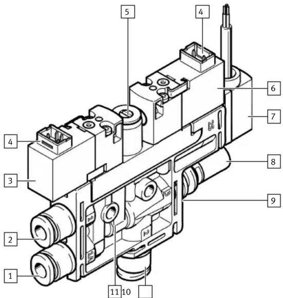
Fig. 1: Product design OVEL-...-H3
1 Supply port for ejector pulse, optional
2 Supply port
3 Solenoid valve for vacuum generation
4 Electrical connection, H3
5 Flow control screw to adjust the intensity of the ejector impulse
6 Solenoid valve for ejector pulse, optional
7 Vacuum sensor, pressure sensor optional
8 Exhaust port, optional silencer
9 Vacuum generator cartridge
10 Vacuum port
11 Housing with mounting holes
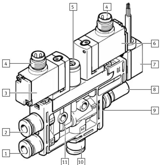
Fig. 2: Product design OVEL-...-R8
1 Supply port for ejector pulse, optional
2 Supply port
3 Solenoid valve for vacuum generation
4 Electrical connection, M8
5 Flow control screw to adjust the intensity of the ejector impulse
6 Solenoid valve for ejector pulse, optional
7 Vacuum sensor, pressure sensor optional
8 Exhaust port, optional silencer
9 Vacuum generator cartridge
10 Vacuum port
11 Housing with mounting hole
5 Function
- The solenoid valve for vacuum controls the supply of compressed air for generating vacuum. A vacuum is generated so long as the vacuum solenoid valve is in the switching position.
- The ejector pulse solenoid valve generates an ejector pulse to release the workpiece safely from the suction cup with connector and to purge the vacuum quickly. A separate operating pressure can be created for the ejector pulse through the optional supply port.
- The vacuum sensor monitors the setpoint value for the generated vacuum.
6 Transport and storage
- Store the product in a cool, dry environment protected from UV and corrosion. Keep storage times short.
7 Assembly

An unfavourable mounting position may impair the function of the product.
- Avoid condensate accumulation in the device through a suitable mounting position.
- Exhaust air must be able to flow out unhindered.
Direct mounting
- Fasten the vacuum generator with 2 M3 screws.
- Tightening torque: 0.6 Nm ± 20 %
Mounting on common supply manifold
The QS fittings are not included with common supply manifold port.

The vacuum generator can be fastened to common supply manifolds with max. 8 positions.
Use mounting kit OABM-MK-G3 → www.festo.com/spareparts.

The vacuum generators with an additional port for ejector pulse (OVEL-...-Z-C-A) cannot be combined with vacuum generators without an additional port (OVEL-...-C-A).
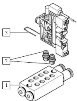
1 Common supply manifold
2 Connecting adapter
3 Supply port clamping clip
Fig. 3: Mounting on common supply manifold
- Screw the connecting adapter [2] into the common supply manifold [1].
- Plug the vacuum generator to the connecting adapter and lock it with the included clamping clip [3].
- Seal unused positions of the common supply manifold with blanking plugs.

An allocation with OVEL-5 and OVEL-7/-10 is possible only with size 15 common supply manifolds.

Installation
8.1 Pneumatic installation
- Connect tubing to the vacuum generator. Recommendation: use PUN type tubing www.festo.com/catalogue.
Circuit symbols of the vacuum generators with vacuum sensor
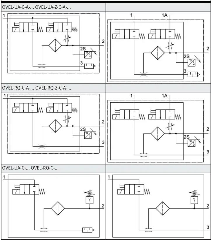
flowchart
graph TD
    A["OVEL-UA-C-A-... OVEL-UA-Z-C-A-..."] --> B["1"]
    B --> C["2"]
    C --> D["3"]
    D --> E["2S"]
    E --> F["1A"]
    F --> G["2S"]
    G --> H["3"]
    H --> I["2"]
    I --> J["2A"]
    J --> K["2"]
    K --> L["2A"]
    L --> M["2A"]
    M --> N["2A"]
    N --> O["2A"]
    O --> P["2A"]
    P --> Q["2A"]
    Q --> R["2A"]
    R --> S["2A"]
    S --> T["2A"]
    T --> U["2A"]
    U --> V["2A"]
    V --> W["2A"]
    W --> X["2A"]
    X --> Y["2A"]
    Y --> Z["2A"]
    Z --> AA["2A"]
    AA --> AB["2A"]
    AB --> AC["2A"]
    AC --> AD["2A"]
    AD --> AE["2A"]
    AE --> AF["2A"]
    AF --> AG["2A"]
Tab. 3: Circuit symbols
Circuit symbols for the vacuum generators without vacuum sensor
| OVEL-UA-C-A OVEL-UA-Z-C-A | |
| 1 | 1 1A 2 2S 3 |
| OVEL-RQ-C-A OVEL-RQ-Z-C-A-... | |
| 1 | 1 1A 2 2S 3 |
| OVEL-UA-C OVEL-RQ-C | |
| 1 | 1 2 2 3 |
Tab. 4: Circuit symbols
8.2 Electrical installation

WARNING
Risk of injury due to electric shock.
- For the electric power supply, use PELV circuits that guarantee a reliable electric disconnection from the mains network.
- Observe IEC 60204-1/EN 60204-1.
- Connect all circuits for the operating and load voltage supply.
- Connect the vacuum generator to the electrical connection. - Max. permissible line length: 30 m.
Pin allocation
| H3 plug Pin Allocation | ||
| 2-+ + -1 | 1 +/- | |
| 2 -/+ |
Tab. 5: Pin allocation of H3 plug
| M8 plug Pin Allocation | ||
| 41 + + 3 | 1 Not assigned | |
| 3 +/- | ||
| 4 -/+ |
Tab. 6: Pin allocation of M8 plug
Circuit diagrams
| OVEL-...B/V OVEL-...PNLK | ||
| P | BN+24 V | P |
| BK | ||
| BU | ||
Tab. 7: Circuit diagrams
9 Commissioning
• Install the device description file IODD.
| iFirmware, software or configuration files → www.festo.com/sp. | ||
| Files Product Content | ||
| Device description file IODD Vacuum generator OVEL IO-Link parameters | ||
Tab. 8: Device description file
9.1 Commissioning the vacuum generator
Requirement: the vacuum generator is fully mounted and connected 7 Assembly.
- Check the operating conditions and critical limits 13 Technical data.
- Apply the operating pressure to the supply port.
- Switch on the operating voltage.
- Activate suction: apply the voltage to both pins of the solenoid valve.
Negative pressure is generated at the vacuum port.
The vacuum generator is ready for operation.
9.2 Setting the intensity of the ejector pulse
Requirement: the vacuum generator is fully commissioned.
- Screw in the flow control screw completely.
The channel for the ejector pulse is closed. An ejector pulse is not generated. Leakage is possible.
- Switch on the vacuum generation.
A negative pressure is generated at the vacuum port.
- Switch off the vacuum generation.
- Unscrew flow control screw slightly.
- Actuate the ejector pulse.
- Screw the flow control screw out or in to adjust the ejector pulse to the required intensity.
9.3 Commissioning the vacuum sensor
Commissioning the pressure transmitter SPTE 1 Applicable documents.
Commissioning the pressure sensor SPAE 1 Applicable documents.
10 Operation
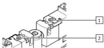
Fig. 4: Manual override of the solenoid valves
1 Manual override of the vacuum solenoid valve
2 Manual override of the ejector pulse solenoid valve
- Press in the manual override plunger [1] or [2] with a blunt pin.
The solenoid valve switches.
- Remove the pin.
The manual override plunger is automatically reset. The solenoid valve returns to the initial position.
11 Maintenance
11.1 Disassembly
- Switch off the power supply:
- Operating voltage
Compressed air
- Disconnect the electrical and pneumatic connections from the device.
- Loosen the mountings and remove the device.
11.2 Replacement
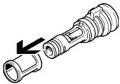
Replacing air filter on OVEL-5
natural_image
Technical line drawing of a flashlight with an arrow indicating the process (no text or symbols present)Fig. 5: Replacing air filter
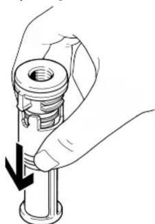
Replacing air filter on OVEL-7/-10
natural_image
Illustration of a hand holding a mechanical component with a downward arrow indicating force or direction (no text or symbols)Fig. 6: Replacing air filter
- Exhaust the vacuum generator.
- Pull out the clamp strap on the vacuum generator cartridge. Do not lose the clamp strap.
- Pull out the vacuum generator cartridge Fig. 5.
- For OVEL-7/-10 only → Fig. 6: place the vacuum generator cartridge with the jet nozzle on a flat surface and press the filter down.
The snap hook unlatches. - Remove the filter.
- Push the new filter on the jet nozzle.
For OVEL-7/-10 only: the snap hook engages. - Push in the vacuum generator cartridge.
- Push the clamping strap on the vacuum generator cartridge until it locks.
Replacing vacuum sensor on OVEL-5
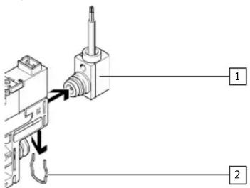
Fig. 7: Replacing vacuum sensor - OVEL-5
1 Vacuum sensor
2 Clamp strap at vacuum sensor port
- Pull out the clamp strap on the vacuum generator cartridge. Do not lose the clamp strap.
- Pull out the vacuum generator cartridge.
- Pull out the clamp strap on the vacuum sensor port.
- Replace the vacuum sensor and lock it with the clamp strap.
- Push in the vacuum generator cartridge.
- Push in the clamp straps at the vacuum sensor port until they lock.
Replacing vacuum sensor on OVEL-7/-10
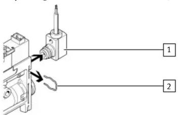
Fig. 8: Replacing vacuum sensor - OVEL-7/-10
1 Vacuum sensor
2 Clamp strap at vacuum sensor port
- Pull out the clamp strap on the vacuum sensor port.
- Replace the vacuum sensor and lock it with the clamp strap.
11.3 Cleaning the device
- Switch off the power supply:
- Operating voltage
Compressed air
-
Clean the device with non-abrasive cleaning agents.
-
Clean the air filter and replace it if necessary.
12 Fault clearance
| Fault description Cause Remedy | ||
| The workpiece is not released from the suction cup with connector. | A device-independent vacuum between the workpiece and the suction gripper. | Activate the ejector pulse when lifting the suction gripper. |
| The ejector pulse is not activated or is not sufficiently dimensioned. | ||
| A device-independent vacuum between the workpiece and the suction gripper. | Increase the intensity of the ejector pulse. | |
| The ejector pulse is not activated or is not sufficiently dimensioned. | ||
| The tubing is incorrectly dimensioned. | Replace the tubing. | |
| The flow control screw is closed. | Open the flow control screw. | |
| The silencer is clogged. Clean the filter is clogged. Clean the filter and replace if necessary. | ||
| The filter is clogged. Clean the filter and replace if necessary. | ||
| The pneumatic line at the vacuum port is kinked. | Avoid kinking the pneumatic lines. | |
Tab. 9: Fault clearance
13 Technical data
| Technical data, general | |||
| OVEL -5 -7 -10 | |||
| Valve function 2/2-way, closed monostable, toward outside | |||
| Mounting position any | |||
| Degree of protection | IP40 | ||
| Corrosion resistance class (CRC) | 2 | ||
| Vibration resistance in accordance with IEC 60068 | 10 ... 60 Hz: 0.35 mm | ||
| 60 ... 150 Hz: 5 g | |||
| Shock resistance in accordance with IEC 60068 | 30 g acceleration with 11 ms duration (half-sine) | ||
Tab. 10: Technical data, general
| Operating conditions | ||||
| OVEL -5 -7 -10 | ||||
| Operating pressure | [MPa] | 0.2 ... 0.7 | ||
| [bar] | 2 ... 7 | |||
| [psi] | 29 ... 102 | |||
| Nominal operating pres-sure | [MPa] | 0.4 | ||
| [bar] | 4 | |||
| [psi] | 58 | |||
| Operating medium Compressed air to ISO 8573-1:2010 [7:4:4] | ||||
| Information on the oper-ating medium | Lubricated operation not possible | |||
Tab. 11: Operating conditions
| Temperature ranges | ||||
| OVEL -5 -7 -10 | ||||
| Ambient temperature | [°C] | 0 ... 50 | ||
| Temperature of medium | [°C] | 0 ... 50 | ||
| Storage temperature | [°C] | -20 ... +60 | ||
Tab. 12: Temperature ranges
| Electrical characteristic values | ||||
| OVEL-5-7-10 | ||||
| Vacuum sensor [V DC] OVEL-...-...B | 10 ... 30 | |||
| Vacuum sensor [V DC] OVEL-...-...V | 18 ... 30 | |||
| Vacuum sensor [V DC] OVEL-...-...PNLK | 18 ... 30 | |||
Electrical characteristic values
| Operating voltage [V DC] Solenoid valve | 24 | |
| Duty cycle Solenoid valve | 100% | |
| Characteristic coil data [W] 1 24 V DC | ||
| Response time [ms] | ≤ 12 | ≤ 22 |
| Protective circuit Solenoid valve | no | |
| Conformity | → www.festo.com/sp | |
Tab. 13: Electrical characteristic values
- FESTO
- Applicable documents
- Safety
- Safety instructions
- Intended use
- Training of qualified personnel
- UL/CSA certification
- WARNING
- Additional information
- Function
- Transport and storage
- Assembly
- Direct mounting
- Mounting on common supply manifold
- Installation
- Pneumatic installation
- Electrical installation
- Risk of injury due to electric shock.
- Setting the intensity of the ejector pulse
- Commissioning the vacuum sensor
- Maintenance
- Disassembly
- Replacement
- Cleaning the device
Brand : Festo
Model : OVEL-7-H-15-P-VQ4-UC-C-A-V1PNLK-H3
Category : Generator