CPX-E-CEC-M1-EP - DJ Equipment Festo - Free user manual and instructions
Find the device manual for free CPX-E-CEC-M1-EP Festo in PDF.


| Product Type | Controller for CPX-E automation system |
| Model | CPX-E-CEC-M1-EP |
| Mounting | H-rail 35 mm × 7.5 mm (EN 60715) |
| Dimensions (W x H x D) | Approx. 30 mm x 100 mm x 75 mm (module only) |
| Weight | Approx. 0.1 kg |
| Operating Voltage (U_EL/SEN) | 24 V DC ±25% |
| Load Voltage (U_OUT) | 24 V DC ±25% |
| Max. Current per Terminal Strip | 8 A |
| Degree of Protection | IP20 |
| Ambient Temperature (Vertical) | -5 °C to +60 °C |
| Ambient Temperature (Horizontal) | -5 °C to +50 °C |
| Pollution Degree | 2 |
| Max. Modules per System | 11 (including bus module/controller) |
| Programming | CODESYS |
| Fieldbus Support | EtherCAT, EtherNet/IP, PROFINET, PROFIBUS |
| Parameterization | Via Festo software or higher-order controller |
| Diagnostics | LED indicators, status bits, I/O diagnostic interface, diagnostic memory |
| Fail-Safe Settings | Configurable output states on communication errors |
| Force Function | Override signal statuses for commissioning |
| Cleaning | Wipe with dry cloth; no solvents |
| Safety | PELV circuits per IEC 60204-1 |
| Certifications | UL, RCM Mark |
Frequently Asked Questions - CPX-E-CEC-M1-EP Festo
User questions about CPX-E-CEC-M1-EP Festo
0 question about this device. Answer the ones you know or ask your own.
Ask a new question about this device
Download the instructions for your DJ Equipment in PDF format for free! Find your manual CPX-E-CEC-M1-EP - Festo and take your electronic device back in hand. On this page are published all the documents necessary for the use of your device. CPX-E-CEC-M1-EP by Festo.
USER MANUAL CPX-E-CEC-M1-EP Festo
natural_image
Isometric line drawing of a multi-chamber industrial control unit (no text or symbols visible)FESTO
Manual | Function, Parameterisation

8192627 2023-09b [8192629]
Translation of the original instructions
CODESYS, EtherCAT, EtherNet/IP, INTEL, IO-Link, MOTOROLA, MODBUS, PI PROFIBUS PROFINET are registered trademarks of the respective trademark owners in certain countries.
Table of contents
1 About this document.... 6
1.1 Applicable documents....6
1.2 Additional information.... 6
1.3 Target group....6
1.4 Product version.... 6
1.5 Product labelling....7
1.6 Specified standards....7
1.7 UL certification....7
2 Function....8
2.1 Overview....8
2.1.1 Functional example....9
2.1.2 CPX-E modules....9
2.1.3 Automation system CPX-E.... 12
2.1.4 Power supply concept.... 14
2.2 Influencing signal statuses....17
2.2.1 Influencing output signals.... 17
2.2.2 Influencing input signals.... 19
2.2.3 Forcing.... 19
2.2.4 Signal status in the event of an error (fail safe).... 21
2.2.5 Signal status in idle state (idle mode).... 24
2.3 Diagnostics options.... 25
2.3.1 LED indicators.... 26
2.3.2 Status bits.... 29
2.3.3 I/O diagnostics interface.... 30
2.3.4 Diagnostic memory.... 34
2.3.5 Error classes.... 37
2.3.6 Error numbers.... 37
3 Parameterisation.... 42
3.1 Parameterisation using Festo software.... 43
3.2 Parameterisation using the higher-order controller.... 43
3.3 Types of parameters.... 43
3.4 Parameters and data of the automation system CPX-E.... 45
3.4.1 Overview.... 45
3.4.2 Function numbers.... 46
3.5 System parameters.... 48
3.5.1 Monitoring....48
3.5.2 Fail safe.... 49
3.5.3 Force mode.... 49
3.5.4 Idle mode....50
3.5.5 System start....50
3.5.6 Analogue process value representation.... 51
3.6 Module parameters (module-specific)....51
3.6.1 Module monitoring....52
3.6.2 Behaviour after short circuit/overload.... 53
3.6.3 Input debounce time....53
3.6.4 Signal extension time....54
3.6.5 Data format for analogue value of inputs/outputs.... 54
3.7 Module parameters (channel-specific).... 55
3.7.1 Signal extension channel x....55
3.7.2 Fail safe channel x....55
3.7.3 Idle mode channel x.... 56
3.7.4 Force channel x....56
3.8 Diagnostic memory parameters (trace parameters)....56
3.8.1 Entries saved retentively with Power ON.... 57
3.8.2 Run/stop filter 1....57
3.8.3 Run/stop filter 2....58
3.8.4 Fault end filter.... 58
3.8.5 Error number filter....59
3.8.6 Module/channel filter....59
3.8.7 Module number....60
3.8.8 Channel number.... 60
3.8.9 Error number....60
3.9 Diagnostic memory data....61
3.9.1 Number of entries in the diagnostic memory....61
3.9.2 Overflow....61
3.9.3 Status....61
3.9.4 Diagnostic memory....61
3.10 System diagnostic data....64
3.10.1 Status bits.... 64
3.10.2 Module number and diagnostic status....64
3.10.3 Error number.... 65
3.11 Module diagnostic data.... 65
3.11.1 Number of the first faulty channel....65
3.11.2 Error number.... 66
3.11.3 Info 2 and 3 (reserved)....66
3.12 System data....67
3.12.1 Configuration....67
3.12.2 Force mode.... 67
3.12.3 System start....68
3.12.4 Fail safe.... 68
3.12.5 Idle mode....68
3.12.6 System monitoring.... 69
3.13 Module data....70
3.13.1 Module code....70
3.13.2 Revision code....70
3.13.3 Serial number.... 71
4 Technical data....71
4.1 Technical data, general....71
4.2 Technical data, electrical....73
4.3 Technical data for UL certification.... 74
1 About this document
This document describes the function and parameterisation of the product series stated in the title. Use of and further information on handling the products are described in other documents 1.1 Applicable documents.
1.1 Applicable documents

All available documents for the product → www.festo.com/sp.
| Document Content | |
| Automation system CPX-E Operating instruction Instruction manual and important information on assembly, electrical installation and maintenance tasks for an automation system CPX-E | |
| Operating instructions and manuals for the CPX-E modules in the automation system CPX-E | Information on using the CPX-E modules |
Tab. 1: Applicable documents
1.2 Additional information
- Contact the regional Festo contact if you have technical problems www.festo.com.
-Accessories and spare parts → www.festo.com/catalogue.

Firmware, software or configuration files → www.festo.com/sp.
| More information Content | |
| Device description files Definition of the modules in an automation system CPX-E for integration into the higher-level controller | |
| Documentation for the higher-order controller and the additional devices in the network | Information on commissioning and parameterisation of the components |
Tab. 2: More information
1.3 Target group
This document is intended for qualified personnel. Experience with electrical control systems is required in order to understand this documentation.
1.4 Product version
This document refers to the automation system CPX-E with CPX-E modules.
The product version can be identified from the product labelling or with the help of appropriate software from Festo.
i
Software suitable for determining the product version is available from Festo in the Support Portal
→ www.festo.com/sp.
Information on using the software can be found in the integrated Help function.
1.5 Product labelling
The CPX-E modules are labelled on the left lateral surface. The product labelling is described in the documentation supplied with the product.
1.6 Specified standards
Version
| DIN 46228-1:1992-08 EN 60529:2013-10 | ||
| DIN 46228-4:1990-09 EN 60715:2001-09 | ||
| EN 60068-2-27:2010-02 IEC 60204-1:2014-10 |
Tab. 3: Standards specified in the document
1.7 UL certification
In combination with the UL inspection mark on the product, the information in this section must also be observed in order to comply with the certification conditions of Underwriters Laboratories Inc. (UL) for USA and Canada.
UL certification information
| Product category code NRAQ/NRAQ7 | |
| File number E239998 | |
| Considered standards UL 61010-1, 3rd Edition, May 11, 2012, revised April 29, 2016CAN/CSA-C22.2 No. 61010-1-12, 3rd Edition, Revision dated April 29, 2016UL 61010-2-201, 1st Edition, Revised February 20, 2017CSA-C22.2 No. 61010-2-201:14, 1st Edition, Issue date January 01, 2014 | |
| UL mark |  US LISTED US LISTED |
Tab. 4: UL certification information
- Technical data and environmental conditions may be subject to change in order to comply with Underwriters Laboratories Inc. (UL) certification requirements for the USA and Canada.
Note deviations → Technical data. - The unit shall be supplied by a power source which fulfils the requirements on a limited-energy circuit in accordance to IEC/EN/UL/CSA 61010-1 or on a Limited Power Source (LPS) in accordance to IEC/EN/UL/CSA 60950-1 or IEC/EN/UL/CSA 62368-1 or a Class 2 circuit in accordance to NEC or CEC.
i
Unauthorised access to the device can cause damage or malfunctions.
When connecting the device to a network:
Protect the network against unauthorised access.
Measures to protect the network include:
- Firewall
• Intrusion Prevention System (IPS)
• Network segmentation - Virtual LAN (VLAN)
• Virtual private Network (VPN)
• Security at physical access level (port security)
For additional information Guidelines and standards for security in information technology, e. g. IEC 62443, ISO/IEC 27001.
i
An access password only protects against unintentional modification.
NOTICE
Modules with Ethernet interfaces should only be operated in networks if all connected network components are supplied by PELV circuits or integrated circuits with equivalent protection.
2 Function
2.1 Overview
The automation system CPX-E is a modular system for the connection of electrical peripherals and it is designed for use in a protected environment. An automation system CPX-E can be connected to a higher-order controller via a network using a bus module or controller or operated autonomously. The behaviour of the automation system CPX-E can be adapted for various requirements by parameterisation.
For example, the following can be influenced by accessing the internal parameters:
- Behaviour of the outputs in the event of communication errors (fail-safe settings)
- Behaviour following fault clearance
-Debounce times and signal extension times for digital input signals
-Force settings (force signal status)
-Operating method of the diagnostic memory
i
CPX-E modules are supplied with preset parameters. You can find the module-specific parameters in the corresponding module documentation.
2.1.1 Functional example
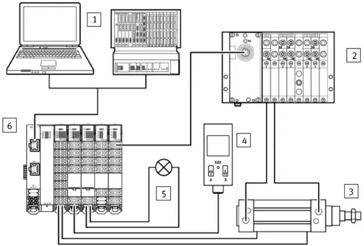
flowchart
graph TD
    A["Laptop"] --> B["PLC"]
    B --> C["Control Panel"]
    C --> D["Industrial Equipment"]
    D --> E["Edit"]
    E --> F["Output Module"]
    style A fill:#f9f,stroke:#333
    style B fill:#ccf,stroke:#333
    style C fill:#cfc,stroke:#333
    style D fill:#fcc,stroke:#333
    style E fill:#cff,stroke:#333
    style F fill:#ffc,stroke:#333
Fig. 1: Functional example
1 Higher-order controller
2 Valve terminal VTUG
3 Standards-based cylinder with proximity switches for position sensing
4 Flow sensor
5 Indicator light
6 Automation system CPX-E with bus module and I/O modules
2.1.2 CPX-E modules
This section presents an overview of the various modules CPX-E that can be used to set up an automation system CPX-E and describes their functions.
i
You can find detailed information about the individual modules in the documentation supplied with each product.
Function
Bus module
A bus module is the interface between an automation system CPX-E and the fieldbus/network, and performs the following functions:
- Connection of the automation system CPX-E to the fieldbus/network
– Data transfer between the automation system CPX-E and the higher-order controller - Transmission of control signals to the connected modules
- Monitoring the functionality of the connected modules
- Read and write access to system parameters, input and output signals and diagnostic data (dependent on the bus module)
-Controller of the automation system CPX-E
Examples of bus modules:
- CPX-E-PB (PROFIBUS DP)
-CPX-E-PN (PROFINET IO)
-CPX-E-EP (EtherNet/IP, Modbus TCP) - CPX-E-EC (EtherCAT)
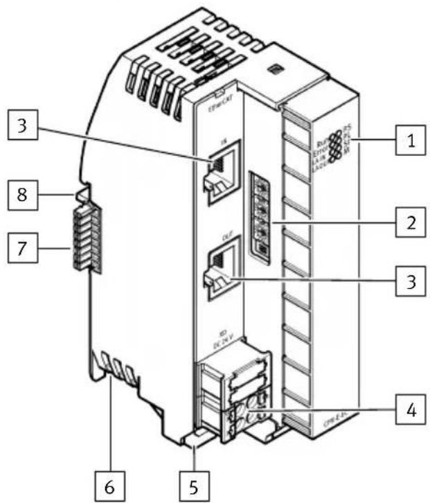
1 LED indicators
2 Rotary and DIL switches
3 Network connection
4 Terminal strip (coded, removable)
5 Terminal strip interlock
6 Module interlock
7 Linkage element
8 Functional earth contact FE
Fig. 2: Bus module product structure (example CPX-E-EC)
i
Rotary and DIL switches are not installed on every bus module.
Controller
A controller is used to control an automation system CPX-E:
- as a stand-alone system controller
- for incorporation into higher-order system controllers via integrated communication interfaces (e.g. PROFINET).
i
Using a controller provides the option of implementing process visualisation via CODESYS in addition to programming.
Examples of controllers:
- CPX-E-CEC-C1
- CPX-E-CEC-M1
-CPX-E-CEC-C1-EP
-CPX-E-CEC-M1-EP - CPX-E-CEC-C1-PN
- CPX-E-CEC-M1-PN
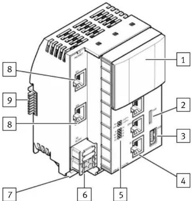
1 Cover (removable)
2 Slot for SD memory card
3 USB interface
4 Ethernet interface
5 LED indicators
6 Terminal strip (coded, removable)
7 Terminal strip interlock
8 Network connection
9 Linkage element
Fig. 3: Controller product structure (example CPX-E-CEC-C1-PN)
Input/output modules
Input or output modules are used to process digital or analogue signals, depending on the module.
Examples of input and output modules:
- Digital input module CPX-E-16DI
- Digital output module CPX-E-8DO
-Analogue input module CPX-E-4AI-U-I
-Analogue output module CPX-E-4AO-U-I - IO-Link master module CPX-E-4IOL
- Counter module CPX-E-1Cl
Function
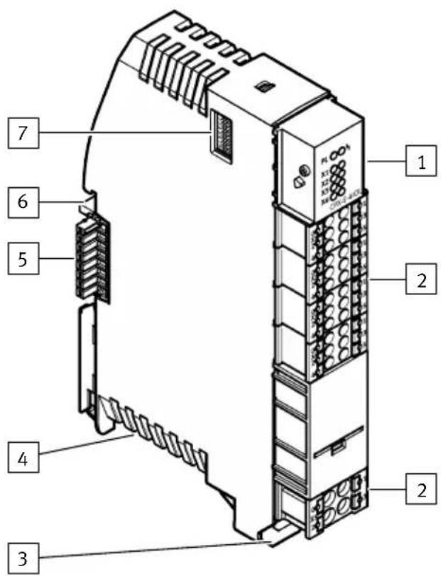
Fig. 4: Input/output module product structure (example IO-Link master module CPX-E-4IOL)
1 LED indicators
2 Terminal strip (coded, removable)
3 Terminal strip interlock
4 Module interlock
5 Linkage element
6 Functional earth contact FE
7 DIL switches
i
DIL switches are not installed on every input/output module.
2.1.3 Automation system CPX-E
2.1.3.1 Rules for set-up
The Automation system CPX-E is basically a bus module or controller and a maximum of 10 additional modules. The bus module or controller is always positioned within an automation system CPX-E as the first module on the left. The other modules can be added in any sequence.
Function
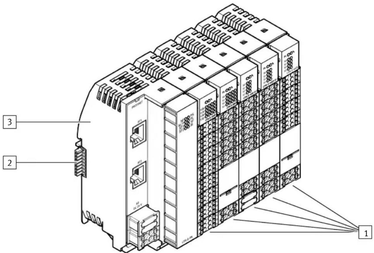
Fig. 5: Structure of the automation system CPX-E (example)
1 Input and output modules
3 Bus module, here CPX-E-PN
2 Linkage element
Input and output modules shown in the picture:
- Digital input module CPX-E-16DI
- Digital output module CPX-E-8DO
-Analogue input module CPX-E-4AI-U-I
-Analogue output module CPX-E-4AO-U-I - IO-Link master module CPX-E-4IOL
2.1.3.2 H-rail mounting
The modules are mounted on an H-rail 35 mm × 7.5 mm in accordance with EN 60715.
i
When selecting screws for H-rail mounting, a distance of 3 mm between the H-rail and the linkage elements must be maintained.
The distance between the retaining screws for mounting the H-rail must not exceed a maximum of 50 mm.
Function
2.1.3.3 Mounting clearances
To ensure sufficient ventilation of the modules, maintain the following minimum clearances when mounting the automation system CPX-E.
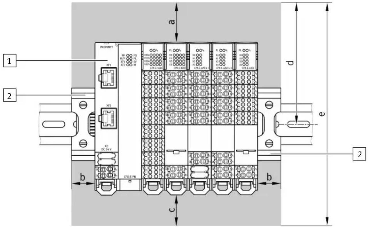
Fig. 6: Mounting clearances
1 Automation system CPX-E
2 End support
| Dimension a b c d e | |||||
| Minimum clearance [mm] 40 20 30 106 195 |
Tab. 5: Minimum clearances
2.1.4 Power supply concept
The Automation system CPX-E uses separate voltages to supply the electronics and sensors ( U_EL/SEN ) and to supply outputs ( U_OUT ). The equivalent voltage potentials (+24 V DC and 0 V DC) are connected to each other in the terminal strips.
This enables the applicable voltage to be transferred from one module to the next.
Operating power supply U_EL/SEN
The operating voltage supply U_EL/SEN to supply the electronics and sensors is fed in at the bus module or controller and distributed internally to the entire Automation system CPX-E.
Function
| Connection [XD1], [XD2]1) | Signal | |
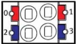 | 0 +24 V DC operating voltage supply U EL/SEN | |
| 1 | ||
| 2 0 V DC operating voltage supply U EL/SEN | ||
| 3 | ||
1) Connections XDx.0 and XDx.1 and also XDx.2 and XDx.3 are each connected to each other in the terminal strip.
Tab. 6: Connection [XD1], [XD2]
i
To comply with the certification requirements of Underwriters Laboratories Inc. (UL) for the USA and Canada, within the scope of UL/CSA, depending on the current consumption, the parallel connection of the operating voltage supply to [XD1] and [XD2] is required 4.3 Technical data for UL certification.
Load voltage supply U_OUT
The load voltage supply Uout to supply the outputs is fed directly to the module separately for every module with outputs. In the following example with the output module CPX-E-8DO this is the output module CPX-E-4AO-UI and the IO-Link master module CPX-E-4IOL.
Function
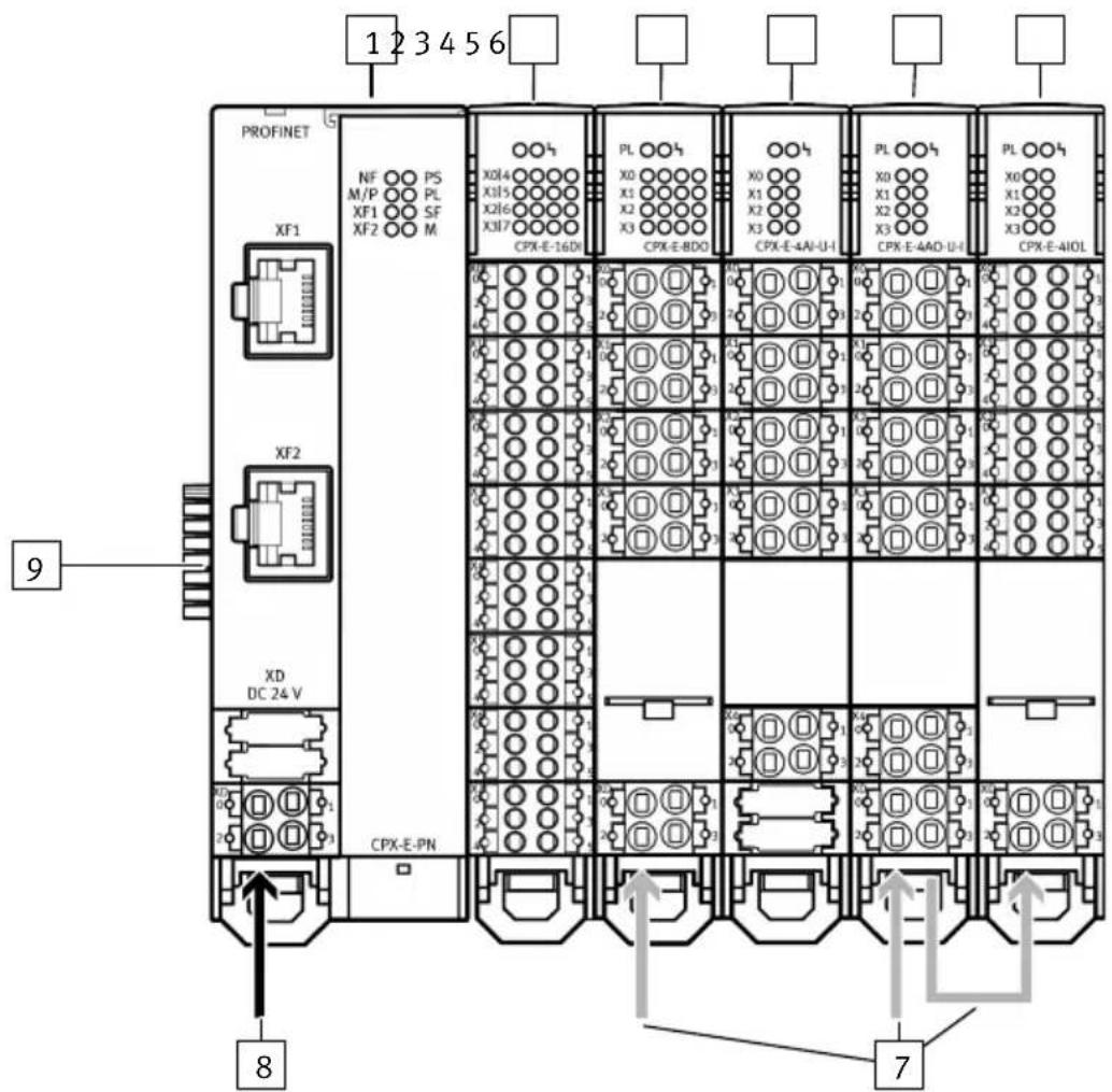
Fig. 7: Power supply concept
1 Bus module CPX-E-PN
2 Input module CPX-E-16DI
3 Output module CPX-E-8DO
4 Input module CPX-E-4AI-U-I
5 Output module CPX-E-4AO-U-I
6 IO-Link master module CPX-E-4IOL
7 Load voltage supply U_OUT
8 Operating power supply U_EL/SEN
9 Linkage element
T
The operating voltage supply U_EL/SEN and load voltage supply U_OUT are routed separately from each other within the automation system CPX-E.
If this separation is not required for the respective use case, both voltages can also be supplied from a common voltage source. In this case, it must be possible to disconnect the load voltage supply separately.
2.2 Influencing signal statuses
| Function Priority 1) | Brief description Signals that can be | influenced | |
| Forcing2) | 1 Influences | signal statuses independently of actual operating statuses → 2.2.3 Forcing. | Input and output signals |
| Fail safe 2 S | Specifies signal | status that take effect in the event of communication errors in the network → 2.2.4 Signal status in the event of an error (fail safe). | Output signals |
| Idle mode3) | 3 Specifies | signal statuses that take effect when switching to Idle status → 2.2.5 Signal status in idle state (idle mode). | Output signals |
1) If several functions are active at the same time
2) Primarily for test purposes during commissioning
3) Only relevant for certain network protocols
Tab. 7: Functions for influencing signal statuses
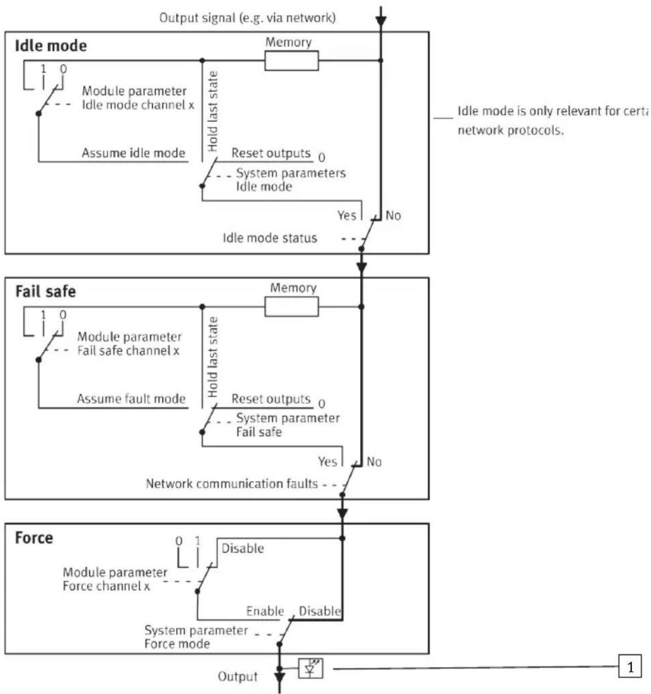
2.2.1 Influencing output signals
The basic settings for the specific function are preset using system parameters.
Setting the system parameter appropriately enables the user to specify the desired signal status for every channel separately using channel-specific module parameters.
Function
flowchart
graph TD
    A["Idle mode"] --> B["Module parameter\nIdle mode channel x"]
    B --> C["Assume idle mode"]
    C --> D["Hold last state"]
    D --> E["Reset outputs 0\nSystem parameters\nIdle mode"]
    E --> F{Yes}
    F -->|No| G["Idle mode status"]
    G --> H["Network communication faults"]
    H --> I{No}
    I --> J["Output"]

    K["Fail safe"] --> L["Module parameter\nFail safe channel x"]
    L --> M["Assume fault mode"]
    M --> N["Hold last state"]
    N --> O["Reset outputs 0\nSystem parameter\nFail safe"]
    O --> P{Yes}
    P -->|No| Q["Network communication faults"]
    Q --> R{No}
    R --> S["Output"]

    T["Force"] --> U["Module parameter\nForce channel x"]
    U --> V{Disable}
    V --> W["Enable"]
    W --> X["Disable"]
    X --> Y["System parameter\nForce mode"]
    Y --> Z["Output"]

    style A fill:#f9f,stroke:#333
    style K fill:#f9f,stroke:#333
    style T fill:#f9f,stroke:#333
Fig. 8: Influencing output signals
1 Status LED for the specific output
Function
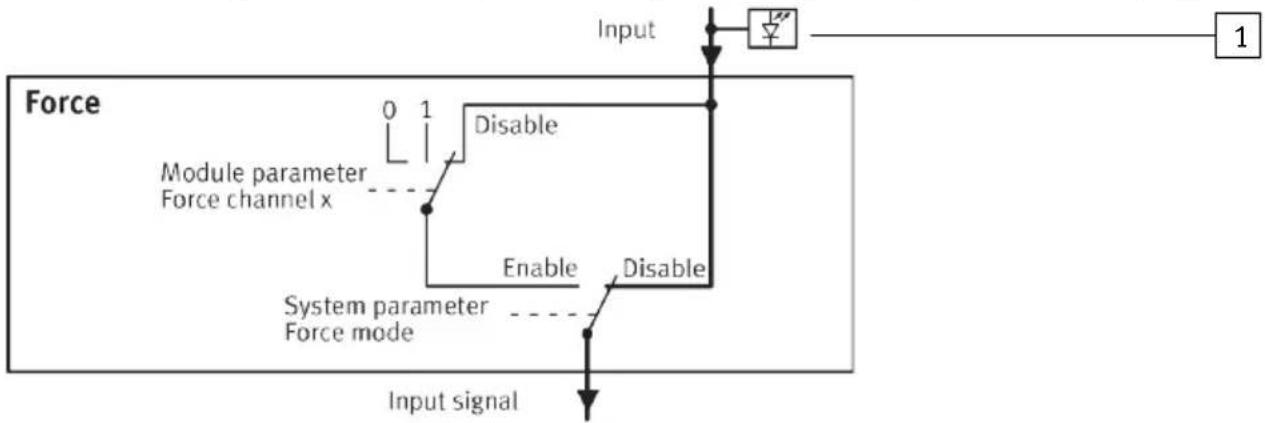
2.2.2 Influencing input signals
Forcing an input does not modify the input signal itself and can also not be observed at the relevant status LED. The logical status of the input only changes internally and may be effective in a program.
flowchart
graph TD
    A["Input Signal"] --> B["Module parameter Force channel x"]
    B --> C["Disable"]
    C --> D["Enable"]
    D --> E["System parameter Force mode"]
    E --> F["Disable"]
    F --> G["Output"]
    style A fill:#f9f,stroke:#333
    style B fill:#ccf,stroke:#333
    style C fill:#cfc,stroke:#333
    style D fill:#fcc,stroke:#333
    style E fill:#cff,stroke:#333
    style F fill:#ffc,stroke:#333
    style G fill:#fcf,stroke:#333
Fig. 9: Influencing input signals
1 Status LED for the specific input
2.2.3 Forcing
2.2.3.1 Basic principles
The Force function enables manipulation of signal states independently of actual operating status. Force enables input and output signals to be overwritten. Input signals that are actually present or changes in status by program will be ignored. The input signals actually pending and the output signals generated by the user program only become valid again when the Force function is deactivated. The Force function is used mainly in the commissioning phase in order to set certain signals to the desired status for test purposes even if the wiring is not complete.
2.2.3.2 Parameterisation
With the automation system CPX-E Force parameterisation can be used for:
-digital inputs and outputs
-Solenoid coils (only in combination with the CPX-E-4IOL module)
-Inputs and outputs of the I/O diagnostic interface and status bits
- analogue inputs and outputs
Force is released or blocked globally for the automation system CPX-E with the "Force mode" system parameter.
| System parameters | Settings Description | |
| Force mode blocked | (default) Force blocked | 1) |
| enabled Force enabled | 1) |
1) The setting is applicable for the complete automation system CPX-E.
Tab. 8: "Force mode" system parameter
The signal status can be specified according to the channel (input/output) for every module.
| Module parameters | Settings Description | |
| Force mode blocked | (default) Force is blocked for the channel. | |
| released Accept the signal status defined by Force state. | ||
| Force state | ||
| Digital signal Reset | signal (default) Reset input/output signal. | |
| Set signal Set input/output signal. | ||
| Analogue signal Analogue value (0 = default) Value of the analogue signal. | ||
Tab. 9: "Force mode" module parameter
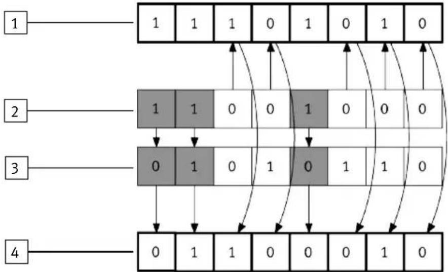
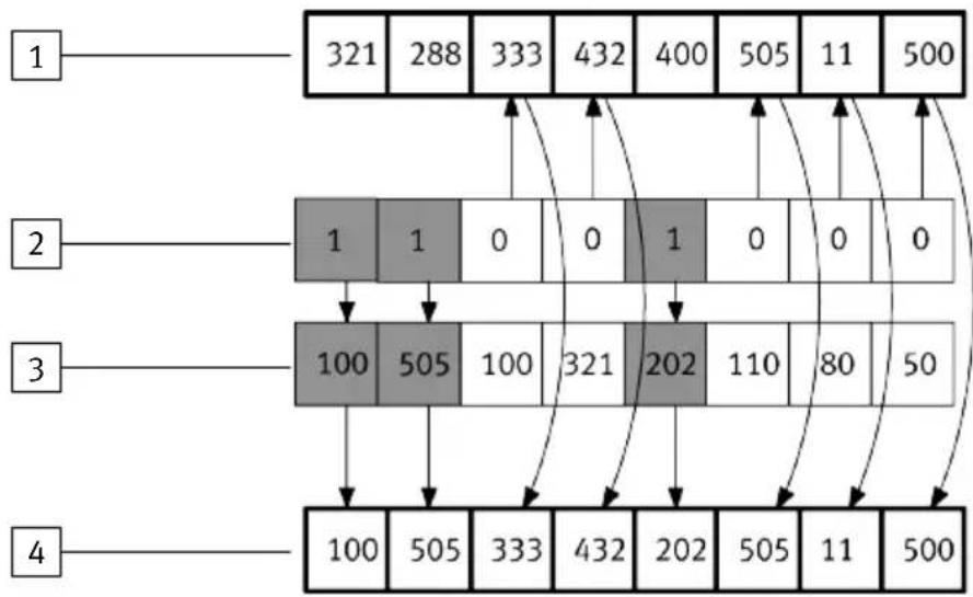
2.2.3.3 Mode of operation
Input information actually present will be replaced by the values entered in the Force table in the process image for the inputs.
Information actually present in the process image for the outputs will be replaced by the values entered in the Force table and transmitted to the physical output.
flowchart
graph TD
    A["1"] --> B["1"]
    A --> C["1"]
    B --> D["0"]
    C --> E["0"]
    D --> F["1"]
    E --> G["1"]
    F --> H["0"]
    G --> I["0"]
    H --> J["1"]
    I --> K["1"]
    J --> L["0"]
    K --> M["0"]
    L --> N["1"]
    M --> O["1"]
    N --> P["0"]
    O --> Q["1"]
    P --> R["0"]
    Q --> S["1"]
    R --> T["0"]
    S --> U["1"]
    T --> V["0"]
    U --> W["1"]
    V --> X["0"]
    W --> Y["1"]
    X --> Z["0"]
Fig. 10: Force parameterisation – example for binary signals
1 Signal status previously
2 Module parameter (according to channel)
Force mode
0 = Force blocked
1 = Force state
3 Module parameter (according to channel)
Force state
0 = reset signal
1 = set signal
4 Signal status afterwards
Function
flowchart
graph TD
    A["1"] --> B["321"]
    A --> C["288"]
    A --> D["333"]
    A --> E["432"]
    A --> F["400"]
    A --> G["505"]
    A --> H["11"]
    A --> I["500"]

    J["2"] --> K["1"]
    J --> L["1"]
    J --> M["0"]
    J --> N["0"]
    J --> O["1"]
    J --> P["0"]
    J --> Q["0"]

    R["3"] --> S["100"]
    R --> T["505"]
    R --> U["100"]
    R --> V["321"]
    R --> W["202"]
    R --> X["110"]
    R --> Y["80"]
    R --> Z["50"]

    AA["4"] --> AB["100"]
    AA --> AC["505"]
    AA --> AD["333"]
    AA --> AE["432"]
    AA --> AF["202"]
    AA --> AG["505"]
    AA --> AH["11"]
    AA --> AI["500"]
Fig. 11: Force parameterisation – example for analogue signals
1 Analogue signal previously
3 Module parameter (according to channel) Force state
2 Module parameter (according to channel) Force mode
4 Analogue signal afterwards
0 = Force blocked
1 = Force value
2.2.4 Signal status in the event of an error (fail safe)
2.2.4.1 Fundamentals
The fail-safe parameterisation is used to help specify the signal status which the outputs are to assume in the event of communication errors in the network (fail-safe status). This should establish a defined machine/system status in the event of communication errors in the network (e.g. failure of the higher-order controller).
2.2.4.2 Parameterisation
With the automation system CPX-E Force fail-safe parameterisation can be used for:
- digital outputs
-analogue outputs
-Solenoid coils (only in combination with the CPX-E-4IOL module or digital outputs)
The “fail safe” system parameter can be used to specify globally the signal status that the outputs are to assume in the event of communication errors in the network, e.g. in the event of:
- Communication failure (network interruption, higher-order controller failure)
-Communication stop
| System parameters | Settings Description | |
| Fail-safe Reset outputs | puts (default) Reset all outputs. | |
| Hold last state Retain current signal status for all outputs. | ||
| Assume Fault mode value Adopt the signal status defined for the relevant channel. | ||
Tab. 10: "Fail-safe" system parameter
i
"Reset outputs" means the following:
• Monostable valves move to the initial position
- Bistable valves remain in the current position
- Mid-position valves go into mid-position (pressurised, exhausted or blocked, depending on valve type).
If "Assume fault mode value" is activated: the signal statuses defined by module parameter for the relevant channel will take effect Tab. 11 "Fail safe" module parameter.
| Module parameters | Settings Description | |
| Fault mode Hold last | state Retain current signal status. | |
| Fault state (default) Accept the signal status defined by Force state. | ||
| Fault state | ||
| Digital signal Reset | output (default) Reset output signal. | |
| Set output Set output signal. | ||
| Analogue signal Analogue value Value of the analogue signal | ||
Tab. 11: "Fail safe" module parameter
Function
2.2.4.3 Mode of operation
The ‘Fault mode’ parameter is used to determine whether the current signal status is to be retained or whether the signal status defined by the ‘Fault state’ parameter is to be assumed.
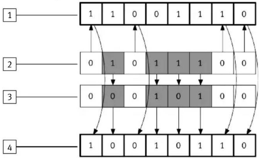
flowchart
graph TD
    A["1"] --> B["0"]
    B --> C["1"]
    C --> D["0"]
    D --> E["1"]
    E --> F["0"]
    F --> G["1"]
    G --> H["0"]
    H --> I["1"]
    I --> J["0"]
    J --> K["1"]
    K --> L["0"]
    L --> M["1"]
    M --> N["0"]
    N --> O["1"]
    O --> P["0"]
    P --> Q["1"]
    Q --> R["0"]
    R --> S["1"]
    S --> T["0"]
    T --> U["1"]
    U --> V["0"]
    V --> W["1"]
    W --> X["0"]
    X --> Y["1"]
    Y --> Z["0"]
    Z --> AA["1"]
    AA --> AB["0"]
    AB --> AC["1"]
    AC --> AD["0"]
    AD --> AE["1"]
    AE --> AF["0"]
    AF --> AG["1"]
    AG --> AH["0"]
Fig. 12: Fail-safe parameterisation – example for binary signals
1 Signal status before the malfunction
2 Module parameter (according to channel)
Fault mode
0 = hold last state
1 = fault state
3 Module parameter (according to channel) Fault state
0 = reset output
1 = set output
4 Signal status after the malfunction
Function
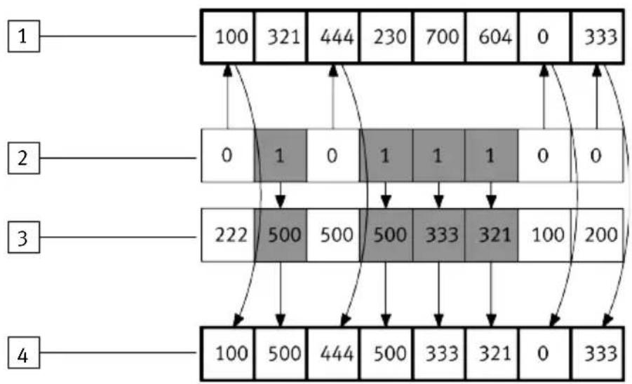
flowchart
graph TD
    A["1"] --> B["100"]
    A --> C["321"]
    A --> D["444"]
    A --> E["230"]
    A --> F["700"]
    A --> G["604"]
    A --> H["0"]
    A --> I["333"]
    J["2"] --> K["0"]
    J --> L["1"]
    J --> M["0"]
    J --> N["1"]
    J --> O["1"]
    J --> P["1"]
    J --> Q["0"]
    J --> R["0"]
    S["3"] --> T["222"]
    S --> U["500"]
    S --> V["500"]
    S --> W["500"]
    S --> X["333"]
    S --> Y["321"]
    S --> Z["100"]
    S --> AA["200"]
    AB["4"] --> AC["100"]
    AB --> AD["500"]
    AB --> AE["444"]
    AB --> AF["500"]
    AB --> AG["333"]
    AB --> AH["321"]
    AB --> AI["0"]
    AB --> AJ["333"]
Fig. 13: Fail-safe parameterisation – example for analogue signals
1 Signal status before the malfunction
2 Module parameter (according to channel)
Fault mode
0 = hold last state
1 = fault state
3 Module parameter (according to channel) Fault state
4 Signal status after the malfunction
2.2.5 Signal status in idle state (idle mode)
2.2.5.1 Basic principles
i
This function is only relevant for certain network protocols → Manual for the specific bus module.
The Idle mode parameterisation is used to help specify the signal status which the outputs are to assume when switching to Idle status. This should establish a defined machine/system status.
2.2.5.2 Parameterisation
With the automation system CPX-E Idle mode parameterisation can be used for:
-digital outputs
- analogue outputs
- Solenoid coils (only in combination with the CPX-E-4IOL module or digital outputs)
The ‘Idle mode’ system parameter can be used to globally specify the signal status which the outputs are to assume when switching to Idle status.
Function
| System parameters | Settings Description | |
| System Idle mode R | Reset output (default). Reset all outputs. | |
| Hold last state Retain current signal status for all outputs. | ||
| Assume Idle mode value. Adopt the signal status defined for the relevant channel. |
Tab. 12: "Idle mode" system parameter
If ‘Assume Idle mode value’ is activated: the signal statuses defined by module parameter for the relevant channel will take effect.
| Module parameters | Settings Description | |
| Idle mode Hold last | state Retain current signal status. | |
| Idle state (default) Accept the signal status defined by Idle state. | ||
| Idle state | ||
| Digital signal Reset | output. Reset output signal. | |
| Set output. Set output signal. | ||
| Analogue signal Analogue value Value of the analogue signal | ||
Tab. 13: "Idle mode" module parameter
2.2.5.3 Mode of operation
The mode of operation is identical to fail-safe parameterisation 2.2.4.3 Mode of operation.
2.3 Diagnostics options
Various options are available for diagnosing errors depending on the parameterisation and network protocol used.
| Diagnostics option | Description | Detailed information |
| LED display components | ||
| System-specific | The system status and errors are displayed directly on the module by LED indicators. | → 2.3.1 LED indicators |
| Module- or network-specific | Module or network status and errors are displayed directly on the module via LED indicators. | → Documentation for the specific module |
| Diagnostics option Description Detailed information | ||
| Internal system diagnostics | ||
| Status bits Common diagnostic messages (global error messages) are displayed by 8 internal inputs (8 status bits). | → 2.3.2 Status bits | |
| I/O diagnostics interface | Diagnostic information for the automation system CPX-E is made available via the I/O diagnostic interface. The I/O diagnostic interface enables bus-independent read access to diagnostic information, data and parameters via 16 internal inputs and outputs. | → 2.3.3 I/O diagnostics interface |
| Network-specific diagnostic functions | Special diagnostic functions or communication services may be available, such as DPV1 for PROFIBUS, depending on the network. | → Documentation for the specific module |
Tab. 14: Diagnostics options
2.3.1 LED indicators
Various LED indicators are available on every module for visualisation of status and errors. A distinction is made here between system-specific LED indicators and those specific to the module or network.
i
The system-specific LED indicators are described in this document.
The LED indicators specific to the module or network are described in the documentation for the respective module.
| Power system [PS] – operating voltage supply U_EL/SEN | |||
| LED (green) Meaning Remedy | |||
 on on | 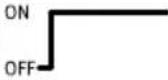 | Power supply present, no error – | |
 flashes flashes | 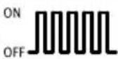 | Power supply present but outside tolerance range | Rectify undervoltage. |
| Linkage on the bus module is missing or incomplete | Check linkage. | ||
 flashes flashes | 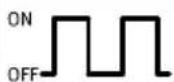 | internal fuse of the power supply has tripped | Correct short circuit or overload. Depending on the parameterisation, the power supply is then switched on again automatically (factory setting) or it must be switched off and then on again. |
 off off | 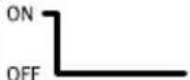 | Power supply not present Check connection of the power supply. | |
Tab. 15: Power system [PS] – operating voltage supply
| Power load [PL] – load voltage supply U_OUT | |||
| LED (green) Meaning Remedy | |||
 on on | 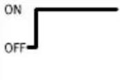 | Power supply present, no error – | |
 flashes flashes | 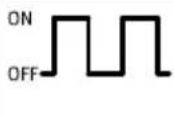 | Power supply present but outside tolerance range | Rectify undervoltage. |
 off off | 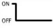 | Power supply not present Check connection of the power supply. | |
Tab. 16: Power load [PL] – load voltage supply
| System failure [SF] – system error | |||
| LED (red)1) | Meaning Remedy | ||
 | 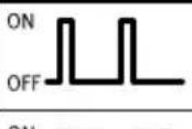 | minor error/information(Error class 1) | → 2.3.5 Error classes |
| flashes | ONOFF | Error(Error class 2) | |
 flashes flashes |  | serious error(Error class 3) |  |
| [3x8K]off | 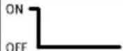 | no error – | |
1) The LED "System Failure" [SF] indicator flashes depending on the error class.
Tab. 17: System failure [SF] – system error
| Modify [M] – parameterisation modified or force active | ||
| LED (yellow) Meaning | ||
 on on | 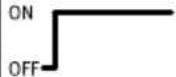 | System start set with saved parameterisation and saved configuration; parameters and configuration are saved to non-volatile memory; external parameterisation is blocked.1)Caution when replacing systems with saved parameterisation.Parameterisation in these systems is not automatically initiated by the higher-order controller on replacement.- Before replacement, note required settings and restore them after replacement, if required. |
 flashes flashes | 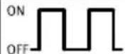 | The force function is enabled.1) |
 off off | 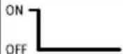 | System start set with default parameterisation (factory setting) and current configuration; external parameterisation is possible (presetting). |
1) The indication of the force function (LED flashing) has priority over indication of the setting for the system start with the saved parameterisation and saved configuration (LED steady).
Tab. 18: Modify [M] – parameterisation modified or force active
2.3.2 Status bits
Regardless of the bus module used, the automation system CPX-E provides 8 status bits for displaying common diagnostic messages (global error messages).
Status bits are configured like inputs. Which input addresses are to be assigned to status bits depend on the network protocol → Manual for the relevant bus module.
i
The status bits supply coded diagnostic information in form of 0 or 1 signals.
If all status bits send a 0-signal, no error is reported.
- Bits 0 ... 3 specify the module types in which faults have occurred.
- Bits 4 ... 7 specify the type of fault.
| Bit Diagnostic information with logic 1 Description | |
| 0 Error at valve Module type in which an error has occurred | |
| 1 Error at output | |
| 2 Error at input | |
| 3 Error in analogue, function or technology module | |
| 4 Undervoltage Type of error | |
| 5 Short circuit/overload | |
| 6 Wire break | |
| 7 other error |
Tab. 19: Bit allocation of the diagnostic information
2.3.2.1 Examples of typical status information
No error signalled
| Type of error Module type | ||||||||
| Other error | Wire break | Short cir- cuit | Under- voltage | Analogue, function | Input Output | Valve | ||
| Bit 7 6 5 4 | 3 2 1 0 | |||||||
| Status 0 0 | 0 0 0 0 0 0 | |||||||
| Short circuit at the output | ||||||||
| Type of error Module type | ||||||||
| Other error | Wire break | Short cir- cuit | Under- voltage | Analogue, function | Input Output | Valve | ||
| Bit 7 6 5 4 | 3 2 1 0 | |||||||
| Status 0 0 | 1 0 0 0 1 0 | |||||||
Tab. 20: "No error signalled" status information (example)
Tab. 21: "Short circuit at output" status information (example)
| Undervoltage of sensor supply | ||||||||
| Type of error Module type | ||||||||
| Other error | Wire break | Short circuit | Under-voltage | Analogue, function | Input Output | Valve | ||
| Bit 7 6 5 4 | 3 2 1 0 | |||||||
| Status 0 0 | 0 1 0 1 0 0 | |||||||
Tab. 22: "Undervoltage of sensor supply" status information (example)
If different errors occur simultaneously on different module types, errors cannot be assigned. To clearly determine errors, the I/O diagnostic interface can be used 2.3.3 I/O diagnostics interface.
2.3.3 I/O diagnostics interface
For networks that do not have extensive diagnostic functions, the diagnostic information for the automation system CPX-E is available via the I/O diagnostic interface. The I/O diagnostic interface enables network-independent read access to diagnostic information, data and parameters via internal inputs and outputs (16 I/16 O).
2.3.3.1 Organisation of internal data and parameters
Internal data and parameters of the modules and of the automation system CPX-E are stored in a common memory area. The I/O diagnostic interface can provide read access to individual bytes of this memory area with the aid of the function number.
i Parameters can be modified with the aid of network-specific functions, depending on the network used → 3 Parameterisation.
2.3.3.2 Mode of operation
Detailed diagnostic information can be accessed via the I/O diagnostic interface.
For example, it is possible to ascertain exactly the module and channel on which an error has occurred.
16 input bits and 16 output bits, through which all diagnostic data can be retrieved, are available for accessing the system diagnostics.
i
The addresses of the input and output bits of the I/O diagnostics interface depend on the network
→ Manual for the relevant bus module.
2.3.3.3 Output bits
The function number of the desired data is specified in binary coded form using the output bits A0 ... A12 of the I/O diagnostic interface. The function number is accepted if control bit O15 returns a logic 1.
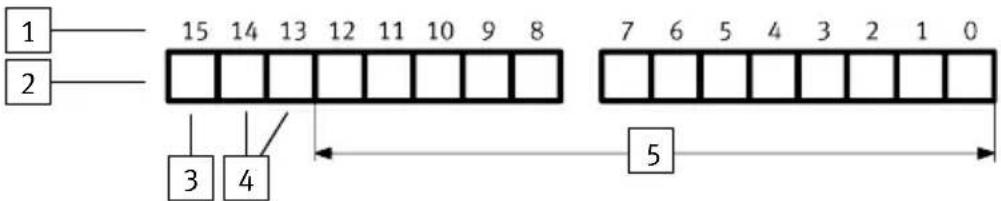
Fig. 14: Output bits
1 Bit number
2 Outputs
3 Control bit
2.3.3.4 Input bits
The response data are output by the automation system CPX-E via the input bits I0 ... I7 when acknowledgement bit I15 returns a logic 1.

Fig. 15: Input bits
1 Bit number
2 Inputs
3 Acknowledgement bit
T
If control bit O15 returns a logic 0, acknowledgement bit I15 will be reset automatically and the status byte will be shown with the diagnostic data bits.
Function
2.3.3.5 Reading out diagnostic data
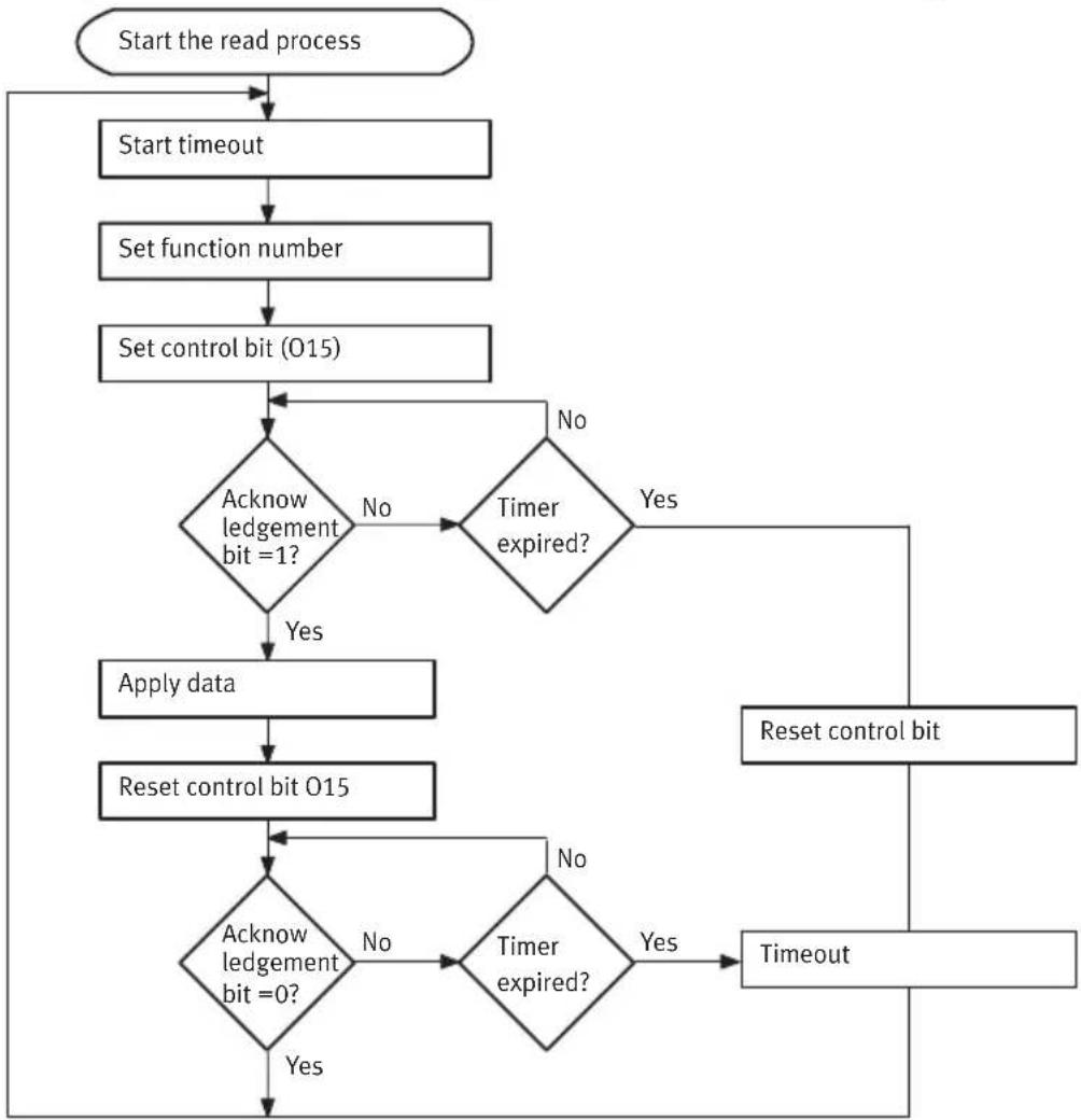
Flow diagram
The function number is applied if there is a rising edge at control bit 015.
The input bits 10 ... 17 return the diagnostic data when the acknowledgement bit returns a logic 1.
flowchart
graph TD
    A["Start the read process"] --> B["Start timeout"]
    B --> C["Set function number"]
    C --> D["Set control bit (015)"]
    D --> E{Acknow ledgement bit = 1?}
    E -->|No| F{Timer expired?}
    F -->|Yes| G["Reset control bit"]
    F -->|No| H["Apply data"]
    H --> I["Reset control bit 015"]
    I --> J{Acknow ledgement bit = 0?}
    J -->|No| K{Timer expired?}
    K -->|Yes| L["Timeout"]
    K -->|No| M["End"]
    L --> G
    M --> G
Fig. 16: Reading out the diagnostic data flow diagram
Example 1: check whether diagnostic data is available
Function number 1937 specifies whether there are diagnostic data and contains, where applicable, the number of the first module on which an error has occurred 3.10.2 Module number and diagnostic status.
-Function number 1937 decimal = 11110010001 binary
Reading out function number 1937
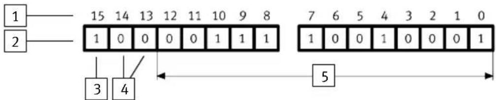
Fig. 17: Reading out function number 1937

Diagnostic data are available if bit 6 returns a logic 1. Bits 0 ... 5 then include the module number of the first faulty module → 3.10.2 Module number and diagnostic status.
For example, if there is an error at module 5 (5 decimal = 101 binary), the following input data would be pending:
Response data (example - error at module 5)
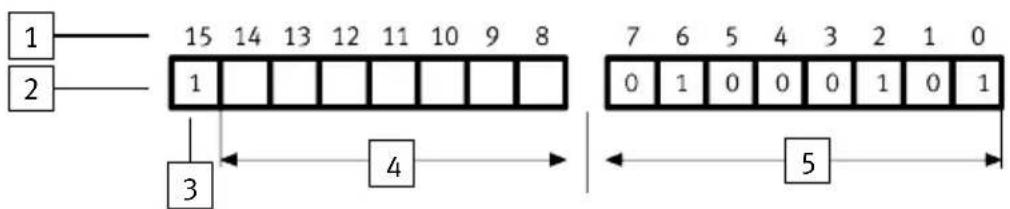
Fig. 18: Response data (example)

i
Detailed information on the module diagnostic data 3.11 Module diagnostic data.
Example 2: read out current error numbers of module 5
The module number of the faulty module can be used to ascertain the function numbers of the relevant module diagnostic data 3.11 Module diagnostic data.
For example, module diagnostic data can be:
-the number of the faulty channel
-the module error number
For example, the following function number can be used to ascertain the module error number of module 5:
-Function number = 2008 + 4 × 5 + 1 = 2029
-2029 decimal = 11111101101 binary
Reading out the module error number of module 5
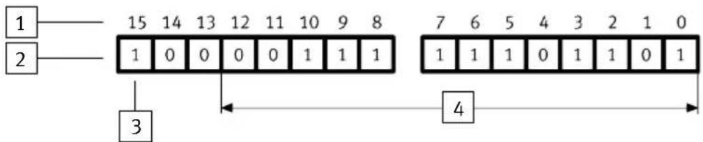
Fig. 19: Reading out the module error number of module 5

The response data for the case in which error number 4 (4 decimal = 100 binary) is pending is shown as an example in the following.
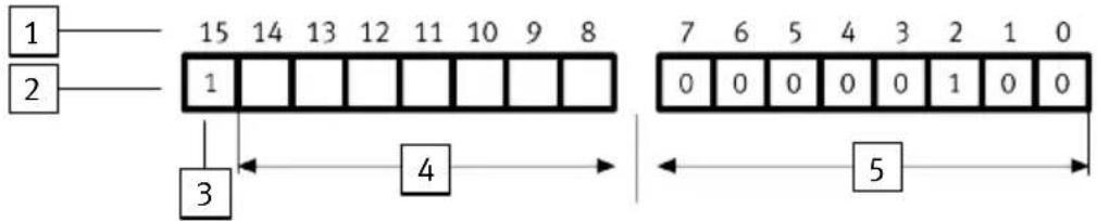
Fig. 20: Response data with error number 4

2.3.4 Diagnostic memory
2.3.4.1 Fundamentals
The diagnostic memory is used for logging error statuses. Recording the time when errors occur, and error sequences makes it easier to find the cause of errors which are otherwise difficult to locate. Errors that occur during operation are entered in the diagnostic memory. Depending on parameterisation, the first or the last 40 entries are saved, as well as the time measured from the moment the power supply was switched on.
Various diagnostic memory filters can be parameterised with diagnostic memory parameters → 3.8 Diagnostic memory parameters (trace parameters). These filters can be used to suppress the recording of specific statuses of the automation system, and to control starting and stopping recording.
The following diagram shows the mode of operation of the diagnostic memory filters.
Function
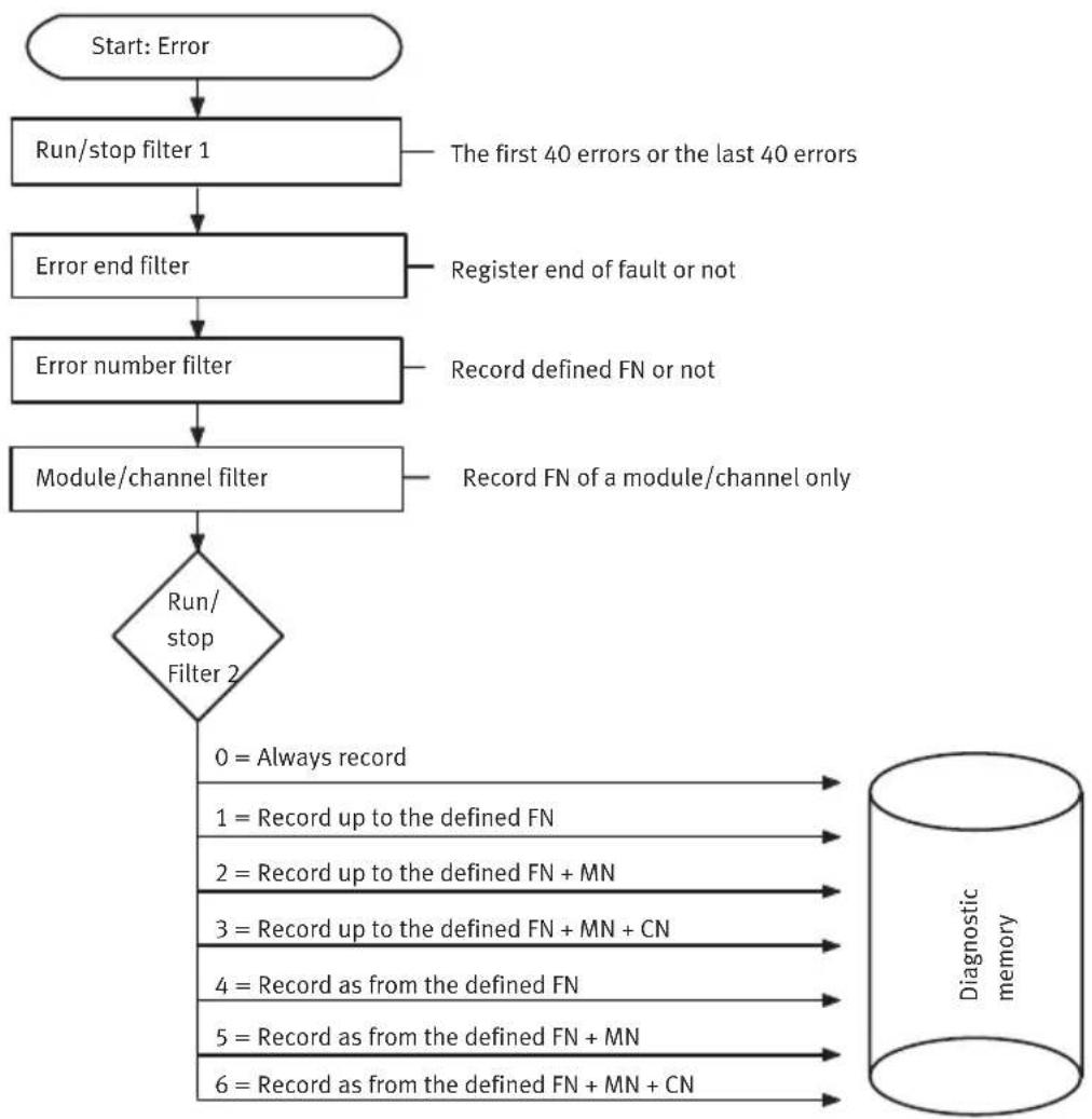
flowchart
graph TD
    A["Start: Error"] --> B["Run/stop filter 1"]
    B --> C["Error end filter"]
    C --> D["Error number filter"]
    D --> E["Module/channel filter"]
    E --> F{Run/stop Filter 2}
    F -->|0 = Always record| G["Diagnostic memory"]
    F -->|1 = Record up to the defined FN| G
    F -->|2 = Record up to the defined FN + MN| G
    F -->|3 = Record up to the defined FN + MN + CN| G
    F -->|4 = Record as from the defined FN| G
    F -->|5 = Record as from the defined FN + MN| G
    F -->|6 = Record as from the defined FN + MN + CN| G
    C -->|The first 40 errors or the last 40 errors| B
    D -->|Register end of fault or not| C
    E -->|Record defined FN or not| D
    E -->|Record FN of a module/channel only| E
MN = Module number
FN = Error number
CN = Channel number
Fig. 21: Mode of operation of the diagnostic memory filters
2.3.4.3 Mode of operation
A maximum of 40 diagnostic messages can be saved in the diagnostic memory. Using appropriate software from Festo or using a controller CPX-E-CEC-... via CODESYS it is possible to parameterise which messages are saved and how these are saved, as well as other functions. This includes how long they are stored for or the diagnostic memory mode ("Entries remanent at Power ON") or the memory procedure ("Run/Stop" setting).
Explanations of the major settings can be found in the following sections.
i
Suitable software for parameterisation is available in the Festo Support Portal → www.festo.com/sp. Information on using the software can be found in the integrated Help function.
Function
Memory duration or diagnostic memory mode
‘Trace parameters’ > ‘Entries remanent at Power ON’ or ‘Diag.Buffer – Mode’:
- 'Active' or 'remanent':
The diagnostic messages remain saved when the operating voltage U_EL/SEN is switched off or after a power failure.
-‘Inactive’ or ‘not remanent’:
The diagnostic messages are lost after the operating voltage U_EL/SEN is switched off or after a power failure.
Memory procedure
‘Trace parameters’ > ‘Run/Stop 1’ or ‘Diag.Buffer – Mode’:
- 'Save first 40 entries' or 'Stop after 40 records...' (stop after 40 entries...):
The bus module saves the first 40 diagnostic messages. Additional, subsequent messages are not saved.
- ‘Stop after 40 records...’ or ‘Record continually...’ (continuous recording...):
Continuous saving of the diagnostic messages. After the 40th message, the oldest message will be overwritten.
Error end filter
‘Trace parameters’ > ‘Fault end filter’ or ‘Diag.Buffer – Error end’:
- ‘Record outgoing faults’ or ‘Record coming/going’ (record incoming/outgoing errors):
When an error occurs and is eliminated, the error number and the time of the event are recorded.
- ‘Do not record outgoing faults’ or ‘Record coming only’ (record incoming errors only):
The error number and the time of the event are recorded only when an error occurs.
If the error is eliminated, the time of the event will not be recorded.
2.3.5 Error classes
Potential errors of the automation system CPX-E are classified in 3 error classes (1 ... 3) with different priority depending on the severity of the error. If an error occurs, the system error LED (SF) flashes to indicate the error class.
| Error class Flashing | sequence of the system errorLED (SF) | Error weighting Priority | |
| 1 1x flashes, pause | time minor low | ||
| 2 2x flashes, pause | time medium medium | ||
| 3 3x flashes, pause | time high high | ||
Tab. 23: Error classes
If multiple errors occur simultaneously, the error with the highest priority will have precedence; in other words:
-The system error LED flashes according to the higher priority.
- The number of the error with the higher priority will be entered in the system diagnostic data under function number 1938 (error number).
Within an error class, errors of modules with a lower module number have higher priority. That means that, within an error class, errors on
- module number 0 have the highest priority
-module number 1 have the second highest priority
一...
2.3.6 Error numbers
| Error numbers (error class 2) | ||
| Error number | Meaning Remedy | |
| 0 no error – | ||
| 1 General diagnostics (module-specific errors) | → Manual for the specific module | |
| 2 Short circuit/overload in sensor supply (SCS) or at output (SCO) | Eliminate short circuit/overload→ Manual for the specific module. | |
| 3 Wire break/idle at current input/output Check cables and sensors/actuators and replace where required. | ||
| 4 Failure of load voltage supply U OUT due to short circuit/overload (output side) | Check actuators and their connections. | |
| 5 Undervoltage in the operating voltage supply UEL/SEN (on input side) | Rectify undervoltage. | |
| 6 ... 8 | reserved – | |
| 9 Value falling | below nominal range Check analogue input | and parameterised limit value. |
| 10 Value exceeding nominal range | ||
| 11 Short circuit at valve Check valve and pneumatic interface. | ||
| 12 reserved – | ||
| 13 Wire break | at valve (open load) Check valve and pneumatic interface. | |
| 14 Limit value | of the condition counter exceeded | Set or delete the limit value of the condition counter by parameterising. |
| 15 Module/channel failed Check module/peripherals and replace if necessary. | ||
| 16 Saved configuration is different from the actual configuration of the automation system | With the automation system CPX-E:Check configuration and save again if necessary → Tab. 39 System parameter – system start.For the bus module:Modify the System Start parameter to “System start with default parameterisation and current CPX-E configuration”.For the controller:Save the actual configuration as the set-point configuration with the CODESYS software. | |
| 17 Saved I/O length of the module is different from the actual configuration of the automation system | → Error number 16 | |
| 18 Number of I/O points exceeded Check DIL switch position and configuration of the automation system → Manual for the specific bus module or the specific controller. | ||
| 19 Nominal service life/life cycle exceeded Replace module or spare part → Manual for the specific module. | ||
| 20 Error in parameterisation – analogue input Check the parameterisation and if necessary repeat using the correct parameters. | ||
| 21 Error in parameterisation – data format | ||
| 22 Error in parameterisation – linear scaling | ||
| 23 Error in parameterisation – measured value smoothing | ||
Error numbers (error class 2)
| Error number | Meaning Remedy | |
| 24 Check the parameterisation on lower limit value | sary repeat using the correct parameters. | |
| 25 Error in parameterisation – upper limit value | ||
| 26 Error in actuator supply Eliminate short circuit/overload and check actuators and actuator supply. | ||
| 27 missing or incorrect spare part Replace module or spare part → Manual for the specific module. | ||
| 28 Alarm value reached Check operating conditions → Manual for the specific module. | ||
| 29 Error in parameterisation Check the parameterisation and if necessary repeat using the correct parameters. | ||
| 30 Error in internal communication (no new output data) | Replace module if switching on and off does not remedy problem. | |
| 31 Bus connection interrupted Restore bus connection or check configuration. | ||
| 32 STI read access defective Repeat STI read access. | ||
| 33 Read access parameter defective Repeat read access parameter. | ||
| 34 ... 36 reserved – | ||
| 37 Malfunction in the controller function (e.g. setpoint value cannot be reached) | Check pressure and actuator supply. | |
| 38 valve not detected Check valve (function/installation) and replace if necessary. | ||
| 39 Service required → Manual for the specific module | ||
| 40 ... 47 reserved – | ||
| 48 Calibration error (factory adjustment missing) | Replace module. | |
| 49 Current loop is in the lower drop-out range Check the installation/parameterisation of the actuator → Manual for the relevant module. | ||
| 50 Current loop is in the upper drop-out range | ||
| 51 Physical limit value for a sensor exceeded:– Process value invalid– Possible hardware damage | Check structure (compliance with module specification), check module for damage and replace if necessary. | |
Error numbers (error class 2)
| Error number | Meaning Remedy | |
| 52 Short circuit | at cold junction compensation | Eliminate short circuit and check connected CJC sensors if necessary. |
| 53 Wire break | at cold junction compensation Check cables | and CJC sensors and replace where required. |
| 54 Calibration | data is faulty Replace module. | |
| 55 Formation | of the process value is invalid due to faulty structure | Check structure (compliance with module specification). |
| 56 ... 63 reserved – | ||
| 64 The number | of modules in the current automation system configuration does not match the saved configuration | Correct configuration or save new configuration. |
| 65 ... 69 reserved – | ||
| 70 Automation | system configuration is greater than the number of stations set | Check DIL switch setting (increase number of stations) |
| 71 Bus connection | interrupted Check network cables. | |
| 72 ... 79 reserved – | ||
| 80 Module-specific malfunction → Manual for the specific module | ||
| 81 ... 99 reserved – | ||
| 100 Error in configuration/parameterisation Check configuration/parameterisation, correct if necessary or repeat commissioning. | ||
| 101 Error executing a positioning job Check the positioning job and correct if necessary. | ||
| 102 Error executing a positioning record | ||
| 103 Error in control or in the parameters of a positioning job | ||
| 104 Error in the process control or the system configuration | Check system configuration, positioning job, I/O signals or system status and correct as necessary. | |
| 105 Error in the peripherals (power supply, operating pressure, etc.) | Check peripherals, power supply and operating pressure. | |
| 106 Error in valve or on axis string Check valves and cables and replace where required. | ||
| 107 Error in controller or servo drive Check the controller or servo drive and replace if necessary. | ||
Error numbers (error class 2)
| Error number | Meaning Remedy | |
| 108 Error in m | measuring system or on axis string Check measuring system and cables and replace where required. | |
| 109 Error in the motor or power unit Check motor or power unit and replace if necessary. | ||
| 110 ... 114 reserved – | ||
| 115 Module/channel in a subordinate system has failed | Check the subordinate module (function/installation) and replace if necessary → Manual for the specific module. | |
Tab. 24: Error numbers (error class 2)
Error numbers (error class 3)
| Errornumber | Meaning Remedy | |
| 128 Hardware | defective Check hardware and replace if necessary. | |
| 129 Bus module | faulty Replace bus module. | |
| 130 System error | on the bus module Replace module if sw | witching on and off does not remedy problem. |
| 131 Error in internal communication during start-up | Check automation system and replace if necessary. | |
| 132 System errors | Replace module if switching on and off | does not remedy problem. |
| 133 ... 134 Module faulty Replace module. | ||
| 135 Error in internal configuration, module malfunction | Check automation system and replace if necessary. | |
| 136 System errors | Replace module if switching on and off | does not remedy problem. |
| 137 Error in internal configuration, module malfunction | Check automation system and replace if necessary. | |
| 138 Error in internal configuration, e.g.: - Module not correctly mounted, plugged in - Module faulty | Check module mounting/arrangement (no gaps in automation system configuration), check module and replace if necessary. | |
| 139 Error when processing cyclical services (e.g. parameters) | Check controller program, check automa-tion system and replace if necessary. | |
| 140 Hardware | defective Identify and replace faulty module. | |
Error numbers (error class 3)
| Errornumber | Meaning Remedy | |
| 141 Malfunction | in internal communication; automation system was not yet operational | Check application environment, check automation system and replace if necessary. |
| 142 | ||
| 143 System errors | Replace module if switching on and off | does not remedy problem. |
| 144 Module does not have a valid licence Procure licence or replace module. | ||
| 145 ... 149 reserved – | ||
| 150 System errors | Replace module if switching on and off | does not remedy problem. |
| 151 ... 199 reserved – | ||
Tab. 25: Error numbers (error class 3)
Error numbers (error class 1)
| Errornumber | Meaning Remedy | |
| 200 Error in parameterisation (parameter transfer failed) | Replace module if switching on and off does not remedy problem. | |
| 201 Address incorrect Check DIL switch position and correct if necessary. | ||
| 202 Initialisation of the protocol chip defective Replace module if switching on and off does not remedy problem. | ||
| 203 reserved – | ||
| 204 Switch setting invalid Check DIL switch position and correct if necessary. | ||
| 205 ... 253 reserved – | ||
| 254 Undervoltage of electronics and sensors Rectify undervoltage. | ||
| 255 Unknown error – | ||
Tab. 26: Error numbers (error class 1)
3 Parameterisation
The behaviour of the automation system CPX-E or the behaviour of individual modules and channels can be adapted to the particular application by parameterisation. Parameterisation can be performed with suitable Festo software or by the higher-order controller. The parameters are preset at the factory.
i
The parameterisation options depend on the installed bus module or controller Manual for the specific bus module/controller.
3.1 Parameterisation using Festo software
i
Suitable software for parameterisation is available in the Festo Support Portal → www.festo.com/sp. Information on using the software can be found in the integrated Help function.
3.2 Parameterisation using the higher-order controller
There are various options for parameterisation of the automation system CPX-E using the higher-order controller.
| Parameterisation options Description/benefits | |
| Interface module or scanner/ master | For example, parameterisation can be ensured in the start-up phase or after network interruptions. |
| User program in the higher-level controller | The parameters can be modified during run-time. |
| Network-specific configurators Pa | parameters can be modified during the commissioning phase or during troubleshooting. |
Tab. 27: Parameterisation options
3.3 Types of parameters
The following parameters are defined:
| Parameter type Description Overview of | parameters | |
| System parameters Influence the | behaviour of the complete automation system CPX-E. | → Tab. 29System parameters |
| Module parameters (module-specific) | Influence the behaviour of a particular module. | → Tab. 30Module parameters |
| Module parameters (channel-specific) | Influence the behaviour of a particular channel. | |
| Diagnostic memory parameters In | fluence the mode of operation of the internal diagnostic memory. | → Tab. 31Diagnostic memory parameters |
Tab. 28: Types of parameters
| System parameters Brief description | |
| Diagnostic monitoring with:– Short circuit/overload– Undervoltage at outputs | Switches monitoring of short circuit/ overload and undervoltage for the entire automation system CPX-E on or off. |
| Signal status in the event of an error (fail-safe parameters) | Defines the status that digital output signals are to assume in the event of communication errors on the network. |
| Signal status in idle mode1) | Defines the status that digital output signals are to assume when switching to Idle status. |
| Force signal status (force parameters) | Manipulation of signal statuses separate from actual operating conditions and independent of the higher-order controller. |
| System start Specifies the start-up behaviour of the automation system CPX-E. | |
| Analogue process value representation (data format)2) | Switches the data format for displaying analogue process values (I/O signals). |
1) This function is only relevant for certain network protocols → Manual for the specific bus module.
2) Special parameter, only available on certain bus modules
Tab. 29: System parameters
| Module parameters Brief description | |
| Module-specific | |
| Diagnostic monitoring with:– Short circuit/overload– Undervoltage– Wire break | Switches monitoring of short circuit/overload and undervoltage on the module on or off. |
| Behaviour after:– Short circuit/overload– Wire break | Specifies, after a short circuit/overload or wire break, whether the power is to remain switched off or whether it is to be switched on again automatically. |
| Input debounce time Serves for trouble-free recognition of digital input signals. | |
| Signal extension time Serves for recognising short signals. | |
| Data format of analogue values → Manual for the specific analogue module | |
| Channel-specific | |
| Signal extension Serves for recognising short signals. | |
| Monitoring wire break Serves for recognising connection errors. | |
| Fault mode Defines the status that the relevant channel is to assume in the event of communication errors on the network. | |
| Fault state | |
| Idle mode1) | Defines the status that digital output signals are to assume when the Idle function is accessed. |
| Idle state1) | |
| Force mode Actual signals are replaced in the process image by the Force settings. | |
| Force state | |
1) This function is only relevant for certain network protocols Manual for the specific bus module.
Tab. 30: Module parameters
| Diagnostic memory parameters Brief description | |
| Entries, saved retentively Specifies whether the contents of the diagnostic memory are to be retained after the power supply is switched on again or whether they are to be deleted. | |
| Diagnostic memory filters:– Run/stop filter 1 + 2– Fault end filter– Error number filter– Module/channel filter | The diagnostic memory filters can be used to suppress the recording of certain error messages, and to control both the start and stop of the error recording. |
Tab. 31: Diagnostic memory parameters
3.4 Parameters and data of the automation system CPX-E
3.4.1 Overview
| Parameter Description | |
| System parameters Specify global system functions for the entire automation system, e.g.: - Diagnostic monitoring- System start | |
| Module parameters Specify module-specific and channel-specific functions for the relevant module, e.g.: -Input debounce time-Signal extension time | |
| Diagnostic memory parameters | Specify the mode of operation of the diagnostic memory |
Tab. 32: Overview of parameters
| Data Description | |
| System diagnostic data | Global information about the system status (e.g. error number, common diagnostic message) |
| Module diagnostic data | Information on locating errors (e.g. error number, number of the first faulty channel etc.) |
| Diagnostic memory data | Entries in the diagnostic memory (maximum 40) |
| System data Information | on global system settings |
| Module data Serial number | , revision code and module code of the modules used |
Tab. 33: Overview of data
3.4.2 Function numbers
| Function number ^1) | Description Data/parameters | See section | |
| 0 Configuration | System data | → 3.12.1 | |
| Force mode System data | → 3.12.2 | ||
| System start System data | → 3.12.3 | ||
| 1 Fail safe System | data | → 3.12.4 | |
| Idle mode System data | → 3.12.5 | ||
| 2 System monitoring | System data | → 3.12.6 | |
| 16 + 16m + 0 Module code | Module data | → 3.13.1 | |
| 16 + 16m + 13 Revision code | Module data | → 3.13.2 | |
| 784 + 4m + 0 ... 3 Serial number | Module data | → 3.13.3 | |
| 1936 Status bits | System diagnostic data | → 3.10.1 | |
| 1937 Module number and diagnostic status | System diagnostic data | → 3.10.2 | |
| 1938 Error number | System diagnostic data | → 3.10.3 | |
| 2008 + 4m + 0 Number of the first faulty channel | Module diagnostic data | → 3.11.1 | |
| 2008 + 4m + 1 Module error number | Module diagnostic data | → 3.11.2 | |
| 2008 + 4m + 2 Info 2 (reserved) | Module diagnostic data | → 3.11.3 | |
| 2008 + 4m + 3 Info 3 (reserved) | Module diagnostic data | → 3.11.3 | |
| 3480 Entries saved retentively with Power ON | Diagnostic memory parameters | → 3.8.1 | |
| Run/stop filter 1 | Diagnostic memory parameters | → 3.8.2 | |
| Function number1) | Description Data/parameters | See section | |
| 3482 Number | of entries in the diagnostic memory | Diagnostic memory data | → 3.9.1 |
| 3483 Overflow | Diagnostic memory data | → 3.9.2 | |
| Status Diagnostic memory data | → 3.9.3 | ||
| 3484 Run/stop | filter 2 Diagnostic memory parameters | → 3.8.3 | |
| Fault end filter Diagnostic memory parameters | → 3.8.4 | ||
| Error number filter Diagnostic memory parameters | → 3.8.5 | ||
| Module/channel filter Diagnostic memory parameters | → 3.8.6 | ||
| 3485 Module | number Diagnostic memory parameters | → 3.8.7 | |
| 3486 Channel | number Diagnostic memory parameters | → 3.8.8 | |
| 3487 Error number | Number Diagnostic memory parameters | → 3.8.9 | |
| 3488 + 10d + 0 ... 92) | Diagnostic memory Diagnostic memory data | → 3.9.4 | |
| 4401 Monitoring | System parameters | → 3.5.1 | |
| 4402 Fail safe | System parameters | → 3.5.2 | |
| Force mode System parameters | → 3.5.3 | ||
| Idle mode | System parameters | → 3.5.4 | |
| System start | System parameters | → 3.5.5 | |
| Analogue process value representation | System parameters | → 3.5.6 | |
| 4828 + 64m + 0 | Module monitoring | Module parameters (module-specific) | → 3.6.1 |
| 4828 + 64m + 1 | Behaviour after short circuit/overload | Module parameters (module-specific) | → 3.6.2 |
| Input debounce time | Module parameters (module-specific) | → 3.6.3 | |
| Signal extension time | Module parameters (module-specific) | → 3.6.4 | |
| 4828 + 64m + 3 | Data format for analogue value of inputs | Module parameters (module-specific) | → 3.6.5 |
| Data format for analogue value of outputs | Module parameters (module-specific) | ||
| 4828 + 64m + 6 | Signal extension channel x | Module parameters (channel-specific) | → 3.7.1 |
| -3) | Fail safe channel x Module parameters (channel-specific) | → 3.7.2 | |
| Idle mode channel x Module parameters (channel-specific) | → 3.7.3 | ||
| Force channel x Module parameters (channel-specific) | → 3.7.4 | ||
| -4) | Number of input bytes (Rx size) | System data (network-specific) – | |
| Number of output bytes (Tx size) | System data (network-specific) – | ||
1) m = module number (counting from left to right, beginning with 0)
2) d = diagnostic event
3) Access is protocol-specific → Bus module manual
4) Only relevant for certain network protocols → Bus module manual
Tab. 34: Function numbers
3.5 System parameters
3.5.1 Monitoring
Activates or deactivates (suppresses) monitoring of short circuit/overload and undervoltage for the entire automation system.
Values: 1 = active (default); 0 = inactive
If monitoring is active, an error reported by the module will be:
- sent to the higher-level master
-entered, if applicable, in the diagnostic memory (depending on the filter settings)
-entered in the module diagnostic data and, if applicable, in the status bits
-indicated by the red common error LED on the module
| System parameter – monitor Selection via parameter | |||||||||
| F no.1)4401 | Bit | ||||||||
| 7 6 5 | 4 3 2 | 1 0 | |||||||
| Short circuit/overload in sensor supply (SCS) | % | ||||||||
| Short circuit/overload at the outputs (SCO) | % | ||||||||
| Undervoltage at outputs (UOUT) | % | ||||||||
1) Function number
Tab. 35: System parameter – monitor
i
Monitoring can also be set separately for each module using the module parameter 'Set module monitoring' 3.6.1 Module monitoring. The mode of operation of the channel error LED remains unaltered.
3.5.2 Fail safe
The ‘Fail safe’ system parameter specifies which signal status the outputs are to assume in the event of communication errors in the network, e.g. in the event of network interruption, failure of the higher-order controller, communication stop.
| System parameter – fail safe Selection via parameter | |||||||||
| F no.1)4402 | Bit | ||||||||
| 7 6 5 | 4 3 2 | 1 0 | |||||||
| Reset all outputs (default) 0 0 | |||||||||
| Hold last state (retain signal status) 0 1 | |||||||||
| Assume Fault mode 1 0 | |||||||||
1) Function number
Tab. 36: System parameter – fail safe
i
When switching from ‘Fault mode assume’ to ‘reset all outputs’ or to ‘Hold last state’ the channel-oriented fail-safe settings (module parameter ‘Fault mode’ and ‘Fault state’) are reset automatically for safety reasons to prevent unwanted signal statuses. The fault mode status is set using the channel-specific module parameters 3.7.2 Fail safe channel x.
3.5.3 Force mode
The ‘Force mode’ system parameter specifies for the entire system whether the Force function is disabled or enabled.
| System parameter – force mode Selection via parameter | |||||||||
| F no.1)4402 | Bit | ||||||||
| 7 6 5 | 4 3 2 | 1 0 | |||||||
| Force mode blocked (default) 0 0 | |||||||||
| Force mode enabled (retain signal status) 0 1 | |||||||||
1) Function number
Tab. 37: System parameter – force mode
T
By changing this parameter, the channel-orientated Force settings (module parameters ‘Force mode’ and ‘Force state’) are reset automatically for safety reasons in the following cases in order to avoid undesired signal statuses:
- Change to Festo software:
When switching from "enabled" to "blocked" - Change over the network:
When switching from "blocked" to "enabled"
Force signals have precedence over fail-safe signals.
3.5.4 Idle mode
The ‘Idle mode’ system parameter defines the signal status that outputs should have if the system switches to the Idle status.
| System parameter – Idle mode1) | Selection via parameter | ||||||||
| F no.2)4402 | Bit | ||||||||
| 7 6 5 | 4 3 2 | 1 0 | |||||||
| Reset all outputs (default) 0 0 | |||||||||
| Hold last state (retain signal status) 0 1 | |||||||||
| Assume Idle mode 1 0 | |||||||||
1) This parameter is only relevant with specific network protocols → Manual for the specific bus module.
2) Function number
Tab. 38: System parameter – Idle mode
i
When switching from 'Idle mode assume' to 'Reset all outputs' or to 'Hold last state' the channel-oriented idle mode settings ('Idle mode' and 'Idle state' module parameters) are automatically reset for safety reasons to prevent undesired signal statuses.
3.5.5 System start
The ‘system start’ system parameter specifies the starting behaviour of the system and saves all current parameter settings and the current configuration.
| System parameter – system start Selection via parameter | |||||||||
| System start with default parameterisation (factory setting) and current CPX configuration; external parameterisation is possible (default) | 0 | ||||||||
| System start with saved parameterisation and saved CPX configuration; parameters and configuration are saved to non-volatile memory; external parameterisation is blocked; the Modify (M) LED on the bus module lights | 1 | ||||||||
1) Function number
Tab. 39: System parameter – system start
i
If bit 6 is set to 1, the current parameter settings will be write-protected, and the current configuration will be saved, except for bit 6 itself and the 'Force channel X' module parameters.
Recommendation:
“System start with default parameterisation and current CPX configuration”. The desired parameterisation can then be created in the start-up phase or after a network interruption, e.g. by the interface module or the scanner/master (depending on the network used).
If “System start with default parameterisation and current CPX configuration” is active, the factory settings for all module and system parameters will be applied after switching on and off.
3.5.6 Analogue process value representation
The ‘analogue process data representation’ system parameter switches the data format or byte sequence for displaying analogue process values.
| System parameter – analogue process value representation1) | Selection via parameter | ||||||||
| F no.2)4402 | Bit | ||||||||
| 7 6 5 | 4 3 2 | 1 0 | |||||||
| Byte sequence INTEL format (default):Least significant bit left, most significant bit right (LSB-MSB)3) | 0 | ||||||||
| Byte sequence MOTOROLA format:Most significant bit left, least significant bit right (MSB-LSB)3) | 1 | ||||||||
1) This parameter is only relevant for specific bus modules → Manual for the specific bus module.
2) Function number
3) LSB = Least Significant Bit; MSB = Most Significant Bit
Tab. 40: System parameter – analogue process value representation
3.6 Module parameters (module-specific)
Module parameters refer to module-specific or channel-specific functions. 64 bytes are available for parameters in each module.
i
You can find detailed information on the module parameters supported by the module along with parameter values and their defaults in the manual for the relevant module.
3.6.1 Module monitoring
Monitoring of the potential errors can be activated or deactivated (suppressed) independently for each module.
Values: 1 = active (default); 0 = inactive
If monitoring is active, an error will be:
- sent to the bus module
- indicated by the common error LED on the module
| Module parameter – module monitoring Selection via parameter | |||||||||
| F no.1)4828 +64m | Bit | ||||||||
| 7 6 5 | 4 3 2 | 1 0 | |||||||
| Short circuit/overload in sensor supply (SCS) + 0 | %1 | ||||||||
| Short circuit/overload at the outputs (SCO) + 0 | %1 | ||||||||
| Undervoltage at outputs (UOUT) + 0 | %1 | ||||||||
| Monitoring of parameterisation errors + 0 | %1 | ||||||||
1) Function number; m = module number (counting from left to right, beginning with 0)
Tab. 41: Module parameter – module monitoring
i
Monitoring can also be set for the entire automation system via the 'Monitoring' system parameter→ 3.5.1 Monitoring.
3.6.2 Behaviour after short circuit/overload
The ‘Behaviour after short circuit/overload’ system parameter specifies whether after a short circuit/overload in the sensor supply or the outputs the relevant voltage is to remain switched off or whether it is to be switched on again automatically.
Values: 1 = switch voltage back on; 0 = voltage remains switched off
| Module parameter – behaviour after short circuit/overload | Selection via parameter | ||||||||
| F no.1)4828 +64m | Bit | ||||||||
| 7 6 5 | 4 3 2 | 1 0 | |||||||
| Short circuit/overload in sensor supply (SCS) + 1 | % | ||||||||
| Short circuit/overload at the outputs (SCO) + 1 | % | ||||||||
| Short circuit/overload at the analogue signal + 1 | % | ||||||||
1) Function number; m = module number (counting from left to right, beginning with 0)
Tab. 42: Module parameter – behaviour after short circuit/overload
i
The “Voltage remains switched off” setting requires the power to be switched off and on again or the set/reset of the relevant signals to recover the voltage.
3.6.3 Input debounce time
The ‘input debounce time’ system parameter specifies when a change of edge of the sensor signal on the relevant module is to be accepted as a logical input signal.
| Module parameter – input debounce time Selection via parameter | |||||||||
| F no.1)4828 +64m | Bit | ||||||||
| 7 6 5 | 4 3 2 | 1 0 | |||||||
| Input debounce time 0.1 ms + 1 0 0 | |||||||||
| Input debounce time 3 ms (typical default) + 1 0 | 1 | ||||||||
| Input debounce time 10 ms + 1 1 0 | |||||||||
| Input debounce time 20 ms + 1 1 1 | |||||||||
1) Function number; m = module number (counting from left to right, beginning with 0)
Tab. 43: Module parameter – input debounce time
i
For more information on this parameter Manual for the relevant module.
3.6.4 Signal extension time
The module parameter specifies the signal extension time for the relevant module.
Signal statuses accepted as logical input signals usually remain valid at least until the specified signal extension time (minimum signal duration) has expired. Changes of edge within the extension time are ignored.
| Module parameter – signal extension time Selection via parameter | |||||||||
| F no.1)4828 +64m | Bit | ||||||||
| 7 6 5 | 4 3 2 | 1 0 | |||||||
| Signal extension time 0.5 ms + 1 0 0 | |||||||||
| Signal extension time 15 ms (typical default) + 1 0 1 | |||||||||
| Signal extension time 50 ms + 1 1 0 | |||||||||
| Signal extension time 100 ms + 1 1 1 | |||||||||
1) Function number; m = module number (counting from left to right, beginning with 0)
Tab. 44: Module parameter – signal extension time
i
The signal extension time can be activated channel-by-channel 3.7.1 Signal extension channel x. For more information on this parameter Manual for the relevant module.
3.6.5 Data format for analogue value of inputs/outputs
The ‘data format analogue value of inputs/outputs’ defines the data format for internal processing of the corresponding analogue values (values Manual for the relevant module).
The choice of data format depends on the network or master and simplifies evaluation of the analogue values.
| Module parameter – data format analogue value of inputs/outputs | Selection via parameter | ||||||||
| F no.1)4828 +64m | Bit | ||||||||
| 7 6 5 | 4 3 2 | 1 0 | |||||||
| Data format for analogue value of inputs + 3 | %1 | %1 | |||||||
| Data format for analogue value of outputs + 3 | %1 | %1 | |||||||
1) Function number; m = module number (counting from left to right, beginning with 0)
Tab. 45: Module parameter – data format analogue value of inputs/outputs
3.7 Module parameters (channel-specific)
3.7.1 Signal extension channel x
The module parameter specifies whether the signal extension for the relevant channel is to be enabled or blocked.
Values: 1 = enabled; 0 = blocked
The signal extension time can be specified separately for each module 3.6.4 Signal extension time.
| Module parameter – signal extension channel x | Selection via parameter | ||||||||
| F no.1)4828 +64m | Bit | ||||||||
| 7 6 5 | 4 3 2 | 1 0 | |||||||
| Signal extension channel 0 + 6 | %1 | ||||||||
| Signal extension channel 1 + 6 | %1 | ||||||||
| Signal extension channel 2 + 6 | %1 | ||||||||
| Signal extension channel 3 + 6 | %1 | ||||||||
| Signal extension channel 4 + 6 | %1 | ||||||||
| Signal extension channel 5 + 6 | %1 | ||||||||
| Signal extension channel 6 + 6 | %1 | ||||||||
| Signal extension channel 7 + 6 | %1 | ||||||||
1) Function number; m = module number (counting from left to right, beginning with 0)
Tab. 46: Module parameter – signal extension channel x
3.7.2 Fail safe channel x
The Fail-safe parameterisation can be used to specify the signal status which the outputs are to assume in the event of communication errors 2.2.4 Signal status in the event of an error (fail safe)
| Module parameter – fail safe channel x Selection | via parameter | |
| Fault mode channel x Hold last state Access is via protocol-specific functions → Manual for the bus module. | ||
| Fault state channel x Reset output (default) | ||
Tab. 47: Module parameter – fail safe channel x
3.7.3 Idle mode channel x
The Idle mode parameterisation can be used to specify the signal status which the outputs are to assume when switching to idle status 2.2.5 Signal status in idle state (idle mode)
| Module parameter – idle mode channel x1) | Selection via parameter | |
| Idle mode channel x Hold | last state Access is via pro | protocol-specific functions→ Manual for the bus module. |
| Idle state (default) | ||
| Idle state channel x Reset | output (default) | |
| Set output | ||
1) Not supported by all bus modules
Tab. 48: Module parameter – idle mode channel x
3.7.4 Force channel x
The Forcen function permits the manipulation of signal states independently of actual operating conditions 2.2.3 Forcing
| Module parameter – force channel x Selection via | parameter | |
| Force mode inputs channel x | blocked (default) Access | is via protocol-specific functions → Manual for the bus module. |
| Force state | ||
| Force state inputs channel x | Set signal | |
| Reset signal (default) | ||
| Force mode outputs channel x | blocked (default) | |
| Force state | ||
| Force state outputs channel x | Set signal | |
| Reset signal (default) | ||
Tab. 49: Module parameter – force channel x
3.8 Diagnostic memory parameters (trace parameters)
The mode of operation of the diagnostic memory can be adapted to individual requirements using the diagnostic memory parameters. The diagnostic memory parameters retain their last setting after the power supply has been switched off and on again and are saved so as to be protected against mains failure.
i
Additional information on the working method of the diagnostic memory 2.3.4 Diagnostic memory.
3.8.1 Entries saved retentively with Power ON
Specifies whether the contents of the diagnostic memory are to be retained after the power supply is switched on again or whether they are to be deleted.
Values: 1 = active (default); 0 = inactive
The diagnostic memory will be deleted if the mode is changed.
| Diagnostic memory parameter – inputs saved at Power ON | Selection via parameter | ||||||||
| F no.1)3480 | Bit | ||||||||
| 7 6 5 | 4 3 2 | 1 0 | |||||||
| Entries saved retentively with renewed switch-on | % | ||||||||
1) Function number
Tab. 50: Diagnostic memory parameter – inputs saved at Power ON
3.8.2 Run/stop filter 1
Diagnostic memory filter which is used to specify whether the first 40 errors or the last 40 errors are to be saved.
The diagnostic memory will be deleted if the mode is changed.
| Diagnostic memory parameter – run/stop filter 1 | Selection via parameter | ||||||||
| F no.1)3480 | Bit | ||||||||
| 7 6 5 | 4 3 2 | 1 0 | |||||||
| Save the first 40 entries; stop after 40 entries 0 | |||||||||
| Save the last 40 entries; overwrite old entries (default) 1 | |||||||||
1) Function number
Tab. 51: Diagnostic memory parameter – run/stop filter 1
3.8.3 Run/stop filter 2
Diagnostic memory filter which is used to determine when the recording of errors is to be started or stopped.
| Diagnostic memory parameter – run/stop filter 21) | Selection via parameter | ||||||||
| F no.2)3484 | Bit | ||||||||
| 765 | 432 | 10 | |||||||
| Run/stop filter 2 inactive (default) 0 0 0 | |||||||||
| record up to the defined FN 0 0 1 | |||||||||
| record up to the defined FN + MN 0 1 0 | |||||||||
| record up to the defined FN + MN + KN 0 1 1 | |||||||||
| record from the defined FN 1 0 0 | |||||||||
| record from the defined FN + MN 1 0 1 | |||||||||
| record from the defined FN + MN + KN 1 1 0 | |||||||||
| reserved 1 1 1 | |||||||||
1) MN = module number, CN = channel number, FN = error number
2) Function number
Tab. 52: Diagnostic memory parameter – run/stop filter 2
i
The relevant numbers are defined by the diagnostic memory parameters ‘module number’ ( 3.8.7 Module number), ‘channel number’ ( 3.8.8 Channel number) and ‘error number’ ( 3.8.9 Error number).
3.8.4 Fault end filter
Diagnostic memory filter which is used to specify whether outgoing errors are to be recorded or not.
| Diagnostic memory parameter – fault end filter | Selection via parameter | ||||||||
| F no.1)3484 | Bit | ||||||||
| 7 6 5 | 4 3 2 | 1 0 | |||||||
| record outgoing errors (end of error); filter inactive (default) | 0 | ||||||||
| do not record outgoing errors (end of error); filter active 1 | |||||||||
1) Function number
Tab. 53: Diagnostic memory parameter – fault end filter
i
Recording the outgoing errors can determine how long an error has existed. Incoming and outgoing errors each represent one entry. With outgoing errors, the error number “0” is entered. A maximum of 40 entries is saved.
3.8.5 Error number filter
This diagnostic memory filter can be used to suppress recording of a desired error message or to record a desired error message only.
| Diagnostic memory parameter – error number filter | Selection via parameter | ||||||||
| F no.1)3484 | Bit | ||||||||
| 7 6 5 | 4 3 2 | 1 0 | |||||||
| Error number filter inactive (default) 0 0 | |||||||||
| record only defined error number 0 1 | |||||||||
| do not record defined error number 1 0 | |||||||||
| reserved 1 1 | |||||||||
1) Function number
Tab. 54: Diagnostic memory parameter – error number filter
i
The relevant number is defined by the diagnostic memory parameters 'error number' ( 3.8.9 Error number).
3.8.6 Module/channel filter
This diagnostic memory filter can be used to suppress the recording of errors of other modules or channels, thereby enabling errors in a particular module or channel to be analysed.
| Diagnostic memory parameter – module/channel filter | Selection via parameter | ||||||||
| F no.1)3484 | Bit | ||||||||
| 7 6 5 | 4 3 2 | 1 0 | |||||||
| Module/channel filter inactive (default) 0 0 | |||||||||
| record the error number of a given module only 0 1 | |||||||||
| record the error number of a given channel only 1 0 | |||||||||
| reserved 1 1 | |||||||||
1) Function number
Tab. 55: Diagnostic memory parameter – module/channel filter
i
The relevant numbers are defined by the diagnostic memory parameters ‘module number’ ( 3.8.7 Module number) and ‘channel number’ ( 3.8.8 Channel number).
3.8.7 Module number
Module number for the diagnostic memory filter.
Only effective if an appropriate diagnostic memory filter is active.
| Diagnostic memory parameter – module number | Selection via parameter | ||||||||
| F no.1)3485 | Bit | ||||||||
| 7 6 5 | 4 3 2 | 1 0 | |||||||
| Module number 0 ... 47 (0 = default) | %1 | %1 | %1 | %1 | %1 | %1 | |||
1) Function number
Tab. 56: Diagnostic memory parameter – module number
3.8.8 Channel number
Channel number for the diagnostic memory filter.
Only effective if an appropriate diagnostic memory filter is active.
| Diagnostic memory parameter – channel number | Selection via parameter | ||||||||
| F no.1)3486 | Bit | ||||||||
| 7 6 5 | 4 3 2 | 1 0 | |||||||
| Channel number 0 ... 63 (0 = default) | %1 | %1 | %1 | %1 | %1 | %1 | |||
1) Function number
Tab. 57: Diagnostic memory parameter – channel number
3.8.9 Error number
Error number for the diagnostic memory filter.
Only effective if an appropriate diagnostic memory filter is active.
| Diagnostic memory parameter – error number | Selection via parameter | ||||||||
| F no.1)3487 | Bit | ||||||||
| 7 6 5 | 4 3 2 | 1 0 | |||||||
| Error number 0 ... 255 (0 = default) | %1 | %1 | %1 | %1 | %1 | %1 | %1 | %1 | |
1) Function number
Tab. 58: Error number 0 ... 255 (0 = default)
3.9 Diagnostic memory data
3.9.1 Number of entries in the diagnostic memory
Specifies the number of entries in the diagnostic memory. Can be used as a loop counter if the complete diagnostic memory is to be read out by PLC program.
| Diagnostic memory data – number of entries in the diagnostic memory | Selection via parameter | ||||||||
| F no.1)3482 | Bit | ||||||||
| 7 6 5 | 4 3 2 | 1 0 | |||||||
| Number of entries in the diagnostic memory (0 ... 40) | %1 | %1 | %1 | %1 | %1 | %1 | |||
1) Function number
Tab. 59: Diagnostic memory data – number of entries in the diagnostic memory
3.9.2 Overflow
Indicates whether the diagnostic memory has overflowed. Overflow means that more than 40 errors have occurred.
The overflow is displayed when the first 40 errors are recorded as well as when the last 40 errors are recorded.
| Diagnostic memory data – overflow Selection via parameter | |||||||||
| F no.1)3483 | Bit | ||||||||
| 7 6 5 | 4 3 2 | 1 0 | |||||||
| No overflow 0 | |||||||||
| Overflow 1 | |||||||||
1) Function number
Tab. 60: Diagnostic memory data – overflow
3.9.3 Status
Indicates whether error recording is active or inactive. Error recording can be stopped and started with the run/stop filters.
| Diagnostic memory data – status Selection via parameter | |||||||||
| F no.1)3483 | Bit | ||||||||
| 7 6 5 | 4 3 2 | 1 0 | |||||||
| Recording active 0 | |||||||||
| Recording inactive 1 | |||||||||
1) Function number
Tab. 61: Diagnostic memory data – status
3.9.4 Diagnostic memory
The diagnostic memory contains a maximum of 40 diagnostic entries, with each diagnostic entry consisting of 10 bytes.
The first 5 bytes contain information on the time of the error and the last 5 bytes contain information about the error.
| Diagnostic memory data – diagnostic memory(10 bytes per entry, 40 entries) | Selection via parameter | ||||||||||
| Byte | Description Value F no. | ^1) 3488 + 10d | Bit | ||||||||
| 7 6 5 | 4 3 | 2 1 0 | |||||||||
| 1 DaysNumber of days ^2) | 0 ... 255 + 0 | %1 | %1 | %1 | %1 | %1 | %1 | %1 | %1 | ||
| 2 HoursNumber of hours ^2) | 0 ... 23 + 1 | %1 | %1 | %1 | %1 | %1 | |||||
| 3 MinutesNumber of minutes ^2) | 0 ... 59 + 2 | %1 | %1 | %1 | %1 | %1 | %1 | ||||
| 4 SecondsNumber of seconds ^2) | 0 ... 59 + 3 | %1 | %1 | %1 | %1 | %1 | %1 | ||||
| 5 MillisecondsNumber of 10 milliseconds ^2) Bit 7 is additionally set if it isthe first entry after a switch-on. | 0 ... 99or128 ... 227 | +4 | %1 | %1 | %1 | %1 | %1 | %1 | %1 | %1 | |
| 6 Module codeModule code of the module thatreported the error | 0 ... 255 + 5 | %1 | %1 | %1 | %1 | %1 | %1 | %1 | %1 | ||
| 7 Module positionModule number of the modulethat signalled the error;63 = error not module-related | 0 ... 47;63 | +6 | %1 | %1 | %1 | %1 | %1 | %1 | |||
| 8 Number of first faulty outputchannel(Bits 0 ... 5; values 0 ... 63) | 0 ... 255 + 7 | 0 0 | %1 | %1 | %1 | %1 | %1 | %1 | |||
| 1 | 0 | %1 | %1 | %1 | %1 | %1 | %1 | ||||
| 0 | 1 | %1 | %1 | %1 | %1 | %1 | %1 | ||||
| %1 | %1 | %1 | %1 | %1 | %1 | ||||||
| 9 Error | number (possible error messages → 2.3.5 Error classes) | 0 ... 255 + 8 | %1 | %1 | %1 | %1 | %1 | %1 | %1 | %1 | |
| 10 Subsequent channelsNumber of subsequent channels with the same error | 0 ... 63 + 9 | %1 | %1 | %1 | %1 | %1 | %1 | ||||
1) Function number; d = diagnostic event 0 ... 39; current diagnostic event = 0
2) Measured from the moment the power supply is switched on
Tab. 62: Diagnostic memory data – diagnostic memory
i
If the error number = 0: the content of this byte is also 0.
If the error number is between 128 ... 199 (error class 3): the content of this byte is not relevant (service required).
3.10 System diagnostic data
3.10.1 Status bits
The 8 status bits display common diagnostic messages.
- Bit 0 ... 3: source of error
- Bit 4 ... 7: type of error
Values: 1 = error pending; 0 = no error
| System diagnostic data – status bits Selection via parameter | |||||||||
| F no.1)1936 | Bit | ||||||||
| 7 6 5 | 4 3 2 | 1 0 | |||||||
| Valve | % | ||||||||
| Output | % | ||||||||
| Input | % | ||||||||
| Analogue/technology module | % | ||||||||
| Undervoltage | % | ||||||||
| Short circuit/overload | % | ||||||||
| Wire break | % | ||||||||
| Other error | % | ||||||||
1) Function number
Tab. 63: System diagnostic data – status bits
3.10.2 Module number and diagnostic status
Indicates whether there are diagnostic data and contains, where applicable, the number of the first module on which an error has occurred.
Values: 1 = diagnostic data available; 0 = no diagnostic data
With the aid of the module number of the faulty module, you can ascertain the function number of the relevant diagnostic data.
| System diagnostic data – module number and diagnostic status | Selection via parameter | ||||||||
| F no.1)1937 | Bit | ||||||||
| 7 6 5 | 4 3 2 | 1 0 | |||||||
| Module number of the first faulty module (0 ... 47) | %1 | %1 | %1 | %1 | %1 | %1 | |||
| Diagnostic status | %1 | ||||||||
1) Function number
Tab. 64: System diagnostic data – module number and diagnostic status
3.10.3 Error number
Current error number (possible error messages è → 2.3.6 Error numbers)
Function number 1937 indicates whether diagnostic data are available → 3.10.2 Module number and diagnostic status.
| System diagnostic data – error number Selection via parameter | |||||||||
| F no.1)1938 | Bit | ||||||||
| 7 6 5 | 4 3 2 | 1 0 | |||||||
| Error number (0 ... 255) | %1 | %1 | %1 | %1 | %1 | %1 | %1 | %1 | |
1) Function number
Tab. 65: System diagnostic data – error number
3.11 Module diagnostic data
The module diagnostic data are attributed to the function numbers 2008 ... 2199. A total of 4 items of diagnostic information are available in 4 consecutive bytes for each module.
The function number of the diagnostic data for the faulty module is therefore calculated as follows:
- Function number = 2008 + (4 x module number) + information number
i
You can ascertain the module number of the first faulty module with the aid of the system diagnostic data (function number 1937) 3.10.2 Module number and diagnostic status.
3.11.1 Number of the first faulty channel
Indicates the number of the first faulty channel.
| Module diagnostic data – number of the first faulty channel | Selection via parameter | ||||||||
| F no.1)2008 + 4m | Bit | ||||||||
| 7 6 5 | 4 3 2 | 1 0 | |||||||
| Channel number (0 ... 63) + 0 | %1 | %1 | %1 | %1 | %1 | %1 | |||
| Number of first faulty output channel + 0 0 0 | |||||||||
| Number of first faulty input channel + 0 1 0 | |||||||||
| Module error + 0 0 1 | |||||||||
| reserved + 0 1 1 | |||||||||
1) Function number; m = module number (counting from left to right, beginning with 0)
Tab. 66: Module diagnostic data – number of the first faulty channel
3.11.2 Error number
Error number (possible error messages 2.3.5 Error classes)
| Module diagnostic data – error number Selection via parameter | ||||||||
| F no.1)2008 +4m | Bit | |||||||
| 7 6 5 | 4 3 2 | 1 0 | ||||||
| Error number (0 ... 255) + 1 | %1 | %1 | %1 | %1 | %1 | %1 | %1 | |
1) Function number; m = module number (counting from left to right, beginning with 0)
Tab. 67: Module diagnostic data – error number
3.11.3 Info 2 and 3 (reserved)
| Module diagnostic data – info 2 (reserved) Selection via parameter | |||||||||
| F no.1)2008 +4m | Bit | ||||||||
| 7 6 5 | 4 3 2 | 1 0 | |||||||
| reserved + 2 | %1 | %1 | %1 | %1 | %1 | %1 | %1 | %1 | |
1) Function number; m = module number (counting from left to right, beginning with 0)
Tab. 68: Module diagnostic data – info 2 (reserved)
| Module diagnostic data – info 3 (reserved) Selection via parameter | ||||||||
| F no.1)2008 +4m | Bit | |||||||
| 765 | 432 | 10 | ||||||
| reserved + 3 | %1 | %1 | %1 | %1 | %1 | %1 | %1 | |
1) Function number; m = module number (counting from left to right, beginning with 0)
Tab. 69: Module diagnostic data – info 3 (reserved)
Parameterisation
3.12 System data
System data provide information about global system settings and the system status.
The system data are not saved to retentive memory and are lost on switching off.
3.12.1 Configuration
Indicates whether the current configuration of the automation system corresponds to the saved configuration.
See also 'system start' system parameter → 3.5.5 System start.
| System data - configuration Selection via parameter | |||||||||
| Uniform configuration 0 | |||||||||
| Non-uniform configuration 1 | |||||||||
1) Function number
Tab. 70: System data – configuration
3.12.2 Force mode
Specifies whether Force is blocked or enabled.
See also system parameter 'Force mode'→ 3.5.3 Force mode.
| System data – force mode Selection via parameter | |||||||||
| F no.1)0 | Bit | ||||||||
| 7 6 5 | 4 3 2 | 1 0 | |||||||
| Force blocked 0 | |||||||||
| Force enabled 1 | |||||||||
1) Function number
Tab. 71: System data – force mode
3.12.3 System start
Specifies how the system start of the automation system is to be carried out. See also 'system start' system parameter 3.5.5 System start.
| System data – system start Selection via parameter | |||||||||
| F no.1)0 | Bit | ||||||||
| 7 6 5 | 4 3 2 | 1 0 | |||||||
| System start with default parameterisation (factory setting) and current configuration | 0 | ||||||||
| System start with saved parameterisation and saved equipment status | 1 | ||||||||
1) Function number
Tab. 72: System data – system start
3.12.4 Fail safe
Indicates whether Fail safe is active or inactive.
| System data – fail safe Selection via parameter | |||||||||
| F no.1) 1 | Bit | ||||||||
| 7 6 5 | 4 3 2 | 1 0 | |||||||
| Reset all outputs 0 0 | |||||||||
| Hold last state (retain signal status) 0 1 | |||||||||
| Assume Fault mode 1 1 | |||||||||
1) Function number
Tab. 73: System data – fail safe
3.12.5 Idle mode
Indicates whether Idle mode is active or inactive.
| System data – idle mode Selection via parameter | |||||||||
| F no.1)1 | Bit | ||||||||
| 7 6 5 | 4 3 2 | 1 0 | |||||||
| Reset all outputs 0 0 | |||||||||
| Hold last state (retain signal status) 0 1 | |||||||||
| Assume Idle mode 1 1 | |||||||||
1) Function number
Tab. 74: System data – idle mode
Parameterisation
3.12.6 System monitoring
Specifies whether the monitoring of short circuit/overload and undervoltage is active or inactive. See also ‘monitor’ system parameter 3.5.1 Monitoring.
| System data – system monitor Selection via parameter | |||||||||
| F no.1)2 | Bit | ||||||||
| 7 6 5 | 4 3 2 | 1 0 | |||||||
| Short circuit/overload in sensor supply (SCS) | %1 | ||||||||
| Short circuit/overload at the outputs (SCO) | %1 | ||||||||
| Undervoltage at outputs (UOUT) | %1 | ||||||||
1) Function number
Tab. 75: System data – system monitor
3.13 Module data
Module data contain information appropriate to the relevant modules and are thus used to identify modules.
3.13.1 Module code
Indicates the module code of the module.
You can find the module codes in the corresponding module documentation.
| Module data – module code Selection via parameter | |||||||||
| F no.1)16 + 16m | Bit | ||||||||
| 7 6 5 | 4 3 2 | 1 0 | |||||||
| reserved (0)Module code (1 ... 245)reserved (246 ... 255) | + 0 | %1 | %1 | %1 | %1 | %1 | %1 | %1 | %1 |
1) Function number; m = module number (counting from left to right, beginning with 0)
Tab. 76: Module data – module code
3.13.2 Revision code
Indicates the output status of the module ( product labelling).
| Module data – revision code Selection via parameter | |||||||||
| F no.1)16 + 16m | Bit | ||||||||
| 7 6 5 | 4 3 2 | 1 0 | |||||||
| Revision code (0 ... 255) + 13 | %1 | %1 | %1 | %1 | %1 | %1 | %1 | %1 | |
1) Function number; m = module number (counting from left to right, beginning with 0)
Tab. 77: Module data – revision code
3.13.3 Serial number
Indicates the serial number of the module (in hexadecimal).
1) Function number; m = module number (counting from left to right, beginning with 0)
Tab. 78: Module data – serial number
4 Technical data
4.1 Technical data, general
| General technical data CPX-E | |
| Certificates, declaration of conformity | → www.festo.com/sp |
| Mounting position Vertical/horizontal | |
| Ambient temperature with [°C] -5 ... +60 vertical mounting position | |
| Ambient temperature with [°C] -5 ... +50 horizontal mounting position | |
| Storage temperature [°C] -20 ... +70 | |
| Humidity (non-condensing) [%] 0 ... 95 | |
| Max. permissible setup alti- [m] 2000 tude above sea level | |
| Degree of protection in accordance with EN 60529 | IP20The degree of protection is not UL-tested. |
| Protection against electric shock (Protection against direct and indirect contact in accordance with IEC 60204-1) | By the use of PELV circuits (Protected extra-low voltage) |
| Certification RCM Mark | |
| Pollution degree 2 | |
| Vibration and shock resistance in accordance with EN 60068 ➔ Tab. 80 Type of severity level (SL) | |
| Vibration (part 2-6) H-rail SL1 | |
| Shock (part 2-27) H-rail SL1 | |
| Continuous shock (part 2-27) H-rail SL1 | |
| Automation system CPX-E | |
| Address volume of the inputs/outputs [Byte] 64/64 (maximum) | |
| Max. number of modules per Automation system CPX-E, including the bus module or controller | 11 |
Tab. 79: General technical data
| Type of severity level (SL) | |||||
| Vibration load | |||||
| Frequency range [Hz] Acceleration | [m/s 2] Deflection [mm] | ||||
| SL1 SL2 SL1 SG2 | SL1 SL2 | ||||
| 2 ... 8 | 2 ... 8 | - | - | ±3.5 | ±3.5 |
| 8 ... 27 | 8 ... 27 | 10 | 10 | - | - |
| 27 ... 58 | 27 ... 60 | - | - | ±0.15 | ±0.35 |
| 58 ... 160 | 60 ... 160 | 20 | 50 | - | - |
| 160 ... 200 | 160 ... 200 | 10 | 10 | - | - |
| Shock load | |||||
| Acceleration [m/s2] Duration [ms] | Shocks per direction | ||||
| SL1 SL2 SL1 SL2 | SL1 SL2 | ||||
| ±150 | ±300 | 11 | 11 | 5 | 5 |
| Continuous shock load | |||||
| Acceleration [m/s2] Duration [ms] | Shocks per direction | ||||
| ±150 | 6 | 1000 | |||
Tab. 80: Type of severity level (SL)
4.2 Technical data, electrical
Power supply
| Operating power supply U_EL/SEN | |
| Nominal operating voltage [V DC] 24 ± 25% | |
| Trigger level, undervoltage [V DC] 17.5 detection | |
| Max. current rating of ter- [A] 8 minal strip | 1) |
| Mains buffering time [ms] module-dependent | 2) |
| Load voltage supply U_OUT | |
| Nominal operating voltage [V DC] 24 ± 25% | 3) |
| Trigger level, undervoltage [V DC] Module-dependent | 2) |
| Max. current rating of ter- [A] 8 minal strip | |
1) Non-conforming operating conditions UL → Documentation of modules
2) → Documentation of the modules
3) The tolerance indication is a deviation with some modules.
Tab. 81: Power supply
| Connection data for the terminal strips 4-pin 6-pin | ||
| Conductor cross section | ||
| Solid [mm 2] 0.14 | ... 1.5 | |
| Flexible [mm 2] 0.14 | ... 2.5 0.14 ... 1.5 | |
| Conductor cross section with wire ferrule | ||
| Without plastic sleeve [mm2] 0.14 | ... 1.5 | |
| With plastic sleeve [mm2] 0.14 | ... 1.5 0.14 ... 1.0 | |
| Length of the wire ferrule without plastic sleeve1) | ||
| Conductor cross section [mm]0.14 ... 1.0 mm2 | 8 ... 10 | |
| Conductor cross section [mm]1.5 mm2 | 8 ... 10 | 10 |
| Connection data for the terminal strips 4-pin 6-pin | |
| Length of the wire ferrule with plastic sleeve2) | |
| Conductor cross section [mm] 8 ... 100.14 ... 0.34 mm2 | |
| Conductor cross section [mm] 8 ... 10 100.5 ... 1.0 mm2 | |
1) in accordance with DIN 46228-1
2) in accordance with DIN 46228-4
Tab. 82: Connection data for the terminal strips
4.3 Technical data for UL certification
| Electrical data and ambient conditions UL | |
| Pollution degree 3 | |
| Installation site for indoor use only | |
| Maximum installation height 2000 m | |
| Protection against mechanical influences | Install the product in housing or control cabinet. |
Tab. 83: Electrical data and ambient conditions UL
| Maximum current rating of operating voltage supply U_EL/SEN UL | |
| Supply via [XD1] connection [A] ≤ 4 | |
| Supply via both [XD1] and [A] > 4 ... 8 [XD2] connections | A |
Tab. 84: Maximum current rating UL
Copyright:
Festo SE & Co. KG
Ruiter Straße 82
73734 Esslingen
Germany
Phone:
+49 711 347-0
- FESTO
- Table of contents
- About this document.... 6
- Function....8
- Parameterisation.... 42
- Module parameters (module-specific)....51
- Module parameters (channel-specific).... 55
- Diagnostic memory parameters (trace parameters)....56
- Diagnostic memory data....61
- System diagnostic data....64
- Module diagnostic data.... 65
- System data....67
- Technical data....71
- About this document
- Applicable documents
- Additional information
- Target group
- Product version
- Product labelling
- Specified standards
- UL certification
- i
- NOTICE
- Function
- Overview
- Functional example
- CPX-E modules
- Function
- Bus module
- Controller
- Input/output modules
- Automation system CPX-E
- Rules for set-up
- H-rail mounting
- Mounting clearances
- Power supply concept
- Operating power supply U_EL/SEN
- Load voltage supply U_OUT
- T
- Influencing signal statuses
- Influencing output signals
- Influencing input signals
- Forcing
- Basic principles
- Parameterisation
- Mode of operation
- Signal status in the event of an error (fail safe)
- Fundamentals
- Parameterisation
- Mode of operation
- Signal status in idle state (idle mode)
- Basic principles
- Parameterisation
- Mode of operation
- Diagnostics options
- LED indicators
- Status bits
- Examples of typical status information
- I/O diagnostics interface
- Organisation of internal data and parameters
- Mode of operation
- Output bits
- Input bits
- Reading out diagnostic data
- Flow diagram
- Example 1: check whether diagnostic data is available
- Example 2: read out current error numbers of module 5
- Reading out the module error number of module 5
- Diagnostic memory
- Fundamentals
- Mode of operation
- Memory duration or diagnostic memory mode
- Memory procedure
- Error end filter
- Error classes
- Error numbers
- Parameterisation
- Parameterisation using Festo software
- Parameterisation using the higher-order controller
- Types of parameters
- Parameters and data of the automation system CPX-E
- Overview
- System parameters
- Monitoring
- Fail safe
- Force mode
- Idle mode
- System start
- Recommendation:
- Analogue process value representation
- Module parameters (module-specific)
- Module monitoring
- Behaviour after short circuit/overload
- Input debounce time
- Signal extension time
- Data format for analogue value of inputs/outputs
- Module parameters (channel-specific)
- Signal extension channel x
- Fail safe channel x
- Idle mode channel x
- Force channel x
- Diagnostic memory parameters (trace parameters)
- Entries saved retentively with Power ON
- Run/stop filter 1
- Run/stop filter 2
- Fault end filter
- Error number filter
- Module/channel filter
- Module number
- Channel number
- Error number
- Diagnostic memory data
- Number of entries in the diagnostic memory
- Overflow
- Status
- Diagnostic memory
- System diagnostic data
- Status bits
- Module number and diagnostic status
- Error number
- Module diagnostic data
- Number of the first faulty channel
- Error number
- Info 2 and 3 (reserved)
- System data
- Configuration
- Force mode
- System start
- Fail safe
- Idle mode
- System monitoring
- Module data
- Module code
- Revision code
- Serial number
- Technical data
- Technical data, general
- Technical data, electrical
- Technical data for UL certification
Brand : Festo
Model : CPX-E-CEC-M1-EP
Category : DJ Equipment