
VIDWALLMNT - Wall mount StarTech.com - Free user manual and instructions
Find the device manual for free VIDWALLMNT StarTech.com in PDF.


| Type | Wall mount |
| Brand | StarTech.com |
| Model | VIDWALLMNT |
| Compatible Screen Size | 45" to 70" |
| Maximum Weight Capacity | 70 kg (154 lb) |
| VESA Compatibility | 200x200, 200x300, 200x400, 300x200, 300x300, 400x200, 400x300, 400x400, 600x200, 600x300, 600x400 |
| Tilt Range | -5° to +3° |
| Level Adjustment | -3° to +3° |
| Depth Adjustment | Yes (via knobs on adjustment module) |
| Horizontal Adjustment | Yes (slide left/right) |
| Vertical Adjustment | Yes (via screws on adapter brackets) |
| Swivel Adjustment | Yes (via knobs on adjustment module) |
| Pop-out Feature | Yes (push TV inward to pop out) |
| Kickstand Feature | Yes (for angled access when popped out) |
| Locking Mechanism | Plastic tabs to prevent pop-out; padlock loop on adapter bracket |
| Wall Compatibility | Wood stud, solid concrete, cinder block |
| Mounting Hardware Included | M5, M6, M8 screws, spacers, washers, concrete anchors, hex key, plastic tabs, stoppers |
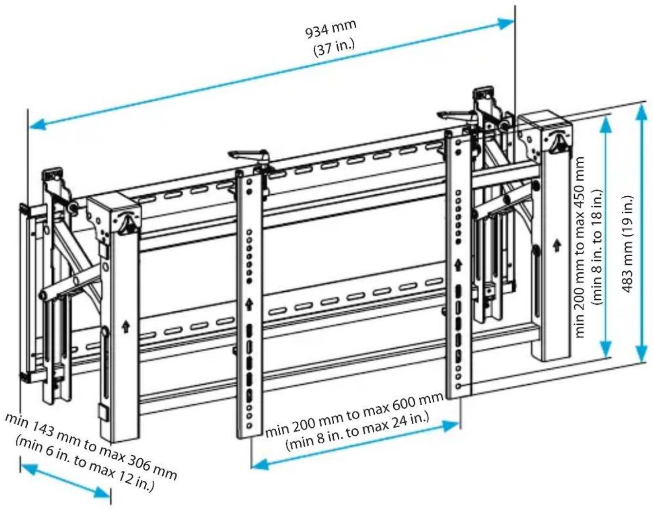
| Product Dimensions (Width x Height x Depth) | 934 x 483 x (200–600) mm (37 x 19 x (8–24) in) approx. |
| Net Weight | Not specified, estimated ~10 kg (22 lb) |
| Material | Metal (steel or aluminum) |
| Usage | Indoor only |
| Warranty | 5 years |
Frequently Asked Questions - VIDWALLMNT StarTech.com
User questions about VIDWALLMNT StarTech.com
0 question about this device. Answer the ones you know or ask your own.
Ask a new question about this device
Download the instructions for your Wall mount in PDF format for free! Find your manual VIDWALLMNT - StarTech.com and take your electronic device back in hand. On this page are published all the documents necessary for the use of your device. VIDWALLMNT by StarTech.com.
USER MANUAL VIDWALLMNT StarTech.com
natural_image
Black metal shelving unit with vertical supports and mounting brackets, no visible text or symbols on the structure itself.*actual product may vary from photos
For the latest information, technical specifications, and support for this product, please visit www.StarTech.com/VIDWALLMNT.
Use of Trademarks, Registered Trademarks, and other Protected Names and Symbols
PHILLIPS® is a registered trademark of Phillips Screw Company in the United States or other countries.
This manual may make reference to trademarks, registered trademarks, and other protected names and/or symbols of third-party companies not related in any way to StarTech.com. Where they occur these references are for illustrative purposes only and do not represent an endorsement of a product or service by StarTech.com, or an endorsement of the product(s) to which this manual applies by the third-party company in question. Regardless of any direct acknowledgement elsewhere in the body of this document, StarTech.com hereby acknowledges that all trademarks, registered trademarks, service marks, and other protected names and/or symbols contained in this manual and related documents are the property of their respective holders.
Warning statements
Make sure that you assemble this product according to the instructions.
Read the entire manual and make sure that you understand the instructions before you start to assemble and use this product.
Never operate this product if parts are missing or damaged.
This product is intended for indoor use only and should not be used outdoors.
Assembling this product is a two-person task. Do not attempt to assemble this product and install equipment without assistance.
When you assemble this product, do not over-tighten the screws. If you encounter resistance while you are tightening the screws, stop tightening.
Make sure that the weight of the display does not exceed the weight capacity of this product. If you exceed the weight capacity, you might experience personal injury or damage to the equipment. This product can support the following weight: 70 kg (154 lb.).
The wall mount is designed to be installed on a wood stud, solid concrete, or clinder block wall. The wall structure should also be capable of supporting at least four times the weight of the mounted equipment. The mounting hardware included with this product may not be adequate for installation on certain wall structures. Failure to comply to these warnings may result in personal injury or damage to the equipment.
The mounting hardware included with this product might not be adequate for some wall structures. If you lack the necessary expertise to attach this product to the wall structure that you're using, contact a construction professional to install the wall mount or to provide specific mounting instructions for your wall structure.
Varningsmeddelanden
Product diagram ......2
Technical specifications ....3
Requirements ....3
Package contents....4
Attach the wall plate to the wall....7
Attach the adjustment module....9
Attach the adapter brackets to the TV....11
Attach the TV to the adjustment module....14
Pop a TV out from the wall 15
Use the kickstand....16
Lock the TV against the wall....16
Adjusting the position of the TV....18
Adjust the horizontal position of the TV....18
Lock the horizontal position of the TV 19
Adjust the tilt angle of the TV....19
Adjust the vertical position of the TV 21
Make the TV level 23
Adjust the depth of the TV....25
Adjust the swivel angle of the TV....27
Adjust the gap between the TVs....29
Technical support....30
Warranty information....30
Product dimensions
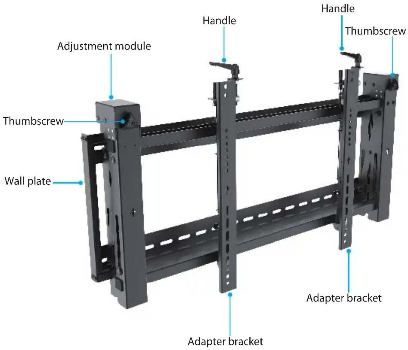
Product diagram
Technical specifications
Type of measurement Measurement
VESA
200x200, 200x300, 200x400
300x200, 300x300
400x200, 400x300, 400x400
600x200, 600x300, 600x400
RATED LOAD
70 kg (154 lb.)
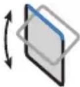
TILT
-5^0 to +3^0
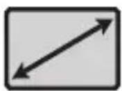
SCREEN
Between 45 in. and 70 in.
*The mount may be visible behind a TV/Display smaller than 45".
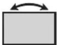
LEVEL
-3^0 to +3^0
Requirements
• TV that is compatible with one of the VESA mounting hole patterns that VIDWALLMNT supports
• Phillips type screwdriver
Package contents
1
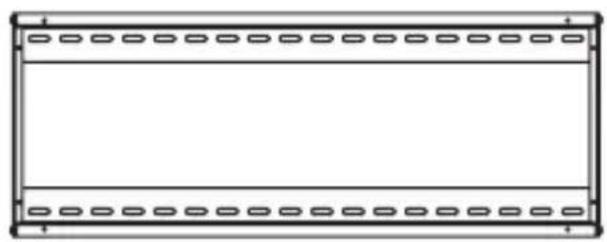
natural_image
Simple line drawing of a rectangular frame with evenly spaced small oval cutouts on both sides (no text or symbols)Wall plate
Qty: One
2
natural_image
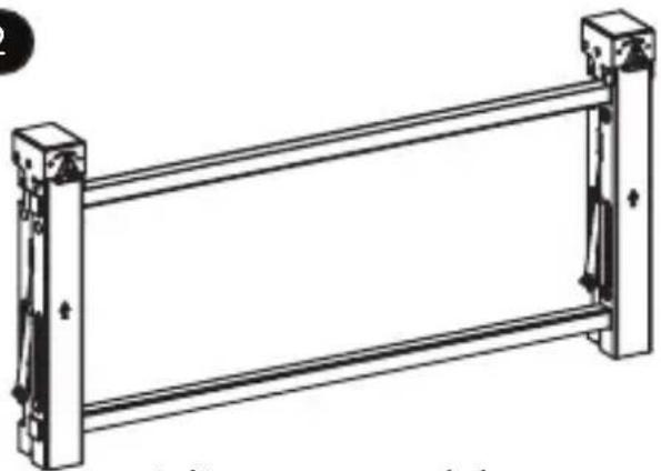
Technical line drawing of a metal frame structure with supports and mounting holes (no text or symbols)Adjustment module
Qty: One
3

natural_image
Line drawing of a mechanical device with ports and lever (no text or symbols)Adapter brackets
Qty: Two
4

Stoppers
Qty: Two
5
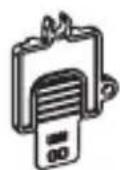
Plastic tabs
Qty: Two
6
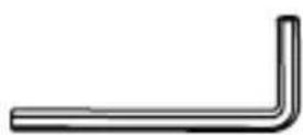
Hex key
Qty: One

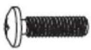
M5x14 mm screws Qty: Four

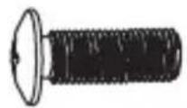
M6x14 mm screws Qty: Four

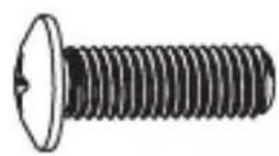
M8x20 mm screws Qty: Four

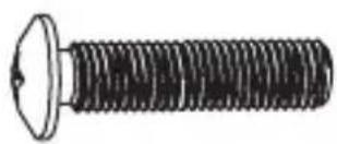
natural_image
Illustration of a bolt with threaded shaft and flange (no text or symbols)M6x30 mm screws Qty: Four

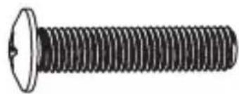
natural_image
Illustration of a standard threaded bolt with a flanged head (no text or symbols)M8x30 mm screws Qty: Four


Rectangular washers Qty: Four
13
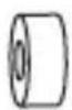
Small spacers
Qty: Eight
14
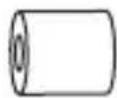
Large spacers
Qty: Four
15
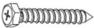
6.3x55 mm screws
Qty: Six
16
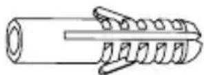
Concrete anchors
Qty: Six
17
Washers
Qty: Six
18
Instruction manual
Qty: One
Warning! Make sure that the weight of the TV doesn't exceed the weight capacity of this product. If you exceed the weight capacity, you might experience personal injury or damage to the product. The video-wall mount can support up to 70 kg (154 lb.).
Attach the wall plate to the wall
Warning! The wall mount is designed to be installed on a wood stud, solid concrete, or cinder block wall. The wall structure should be capable of supporting at least four times the weight of the mounted equipment. The mounting hardware included with this product may not be adequate for installation on certain wall structures. If you lack the necessary expertise to attach this product, contact a construction professional to install the wall mount or to provide specific mounting instructions for your wall structure. Failure to do so may result in personal injury and/or equipment damage.
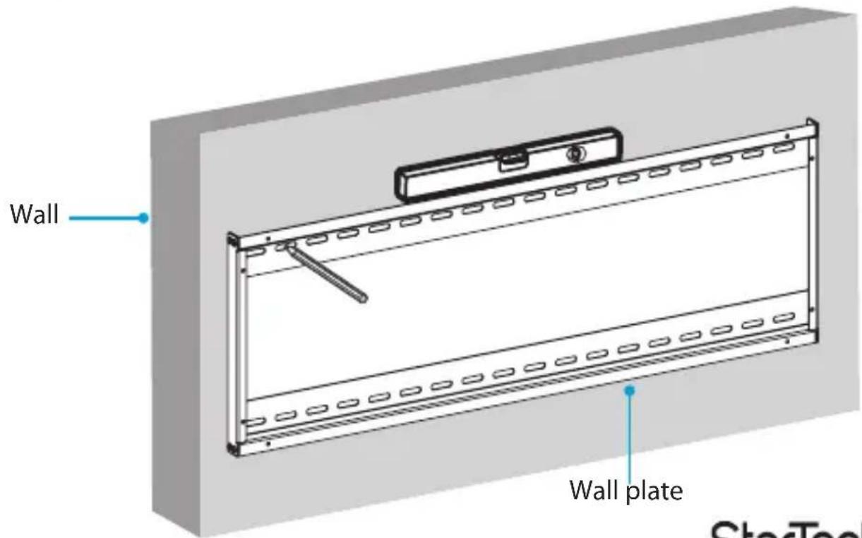
- Measure the width and height of the TVs that you're going to mount.
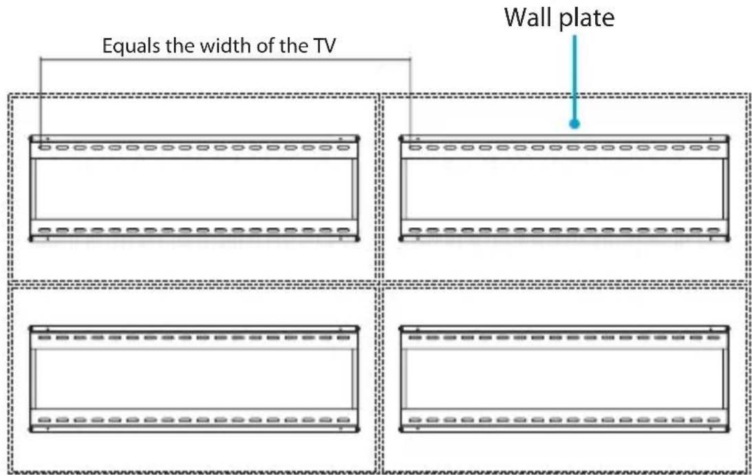
- Position the wall plates horizontally so that the distance between the first holes in each of the wall plates equals the width of the TV that you're mounting. (figure 1)
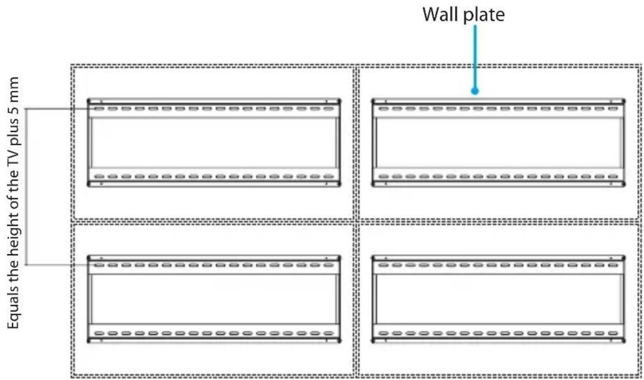
- Position the wall plates vertically so that the distance between the first holes in each of the wall plates equals the height of the TV that you're mounting, plus 5 mm. (figure 2)
- Use the wall plates as templates and mark the wall to indicate where to insert the
figure 1
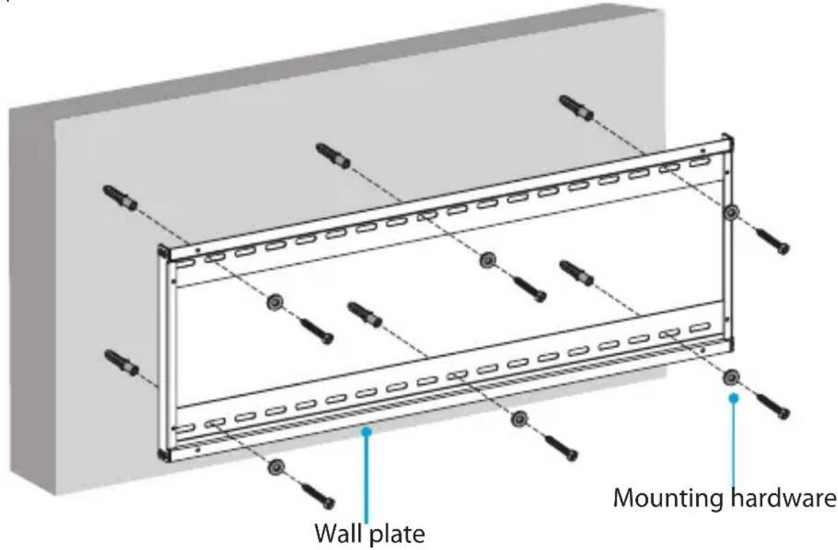
mounting hardware. (figure 3)
- Follow the appropriate steps for the type of wall that you're using and attach the wall plate to the wall. (figure 4)
figure 2
Attach the adjustment module
figure 3
Instruction manual
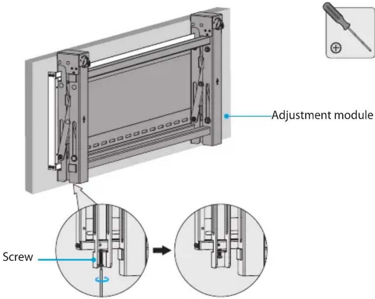
Note: It may require two people to attach the adjustment module to the wall plate.
figure 4
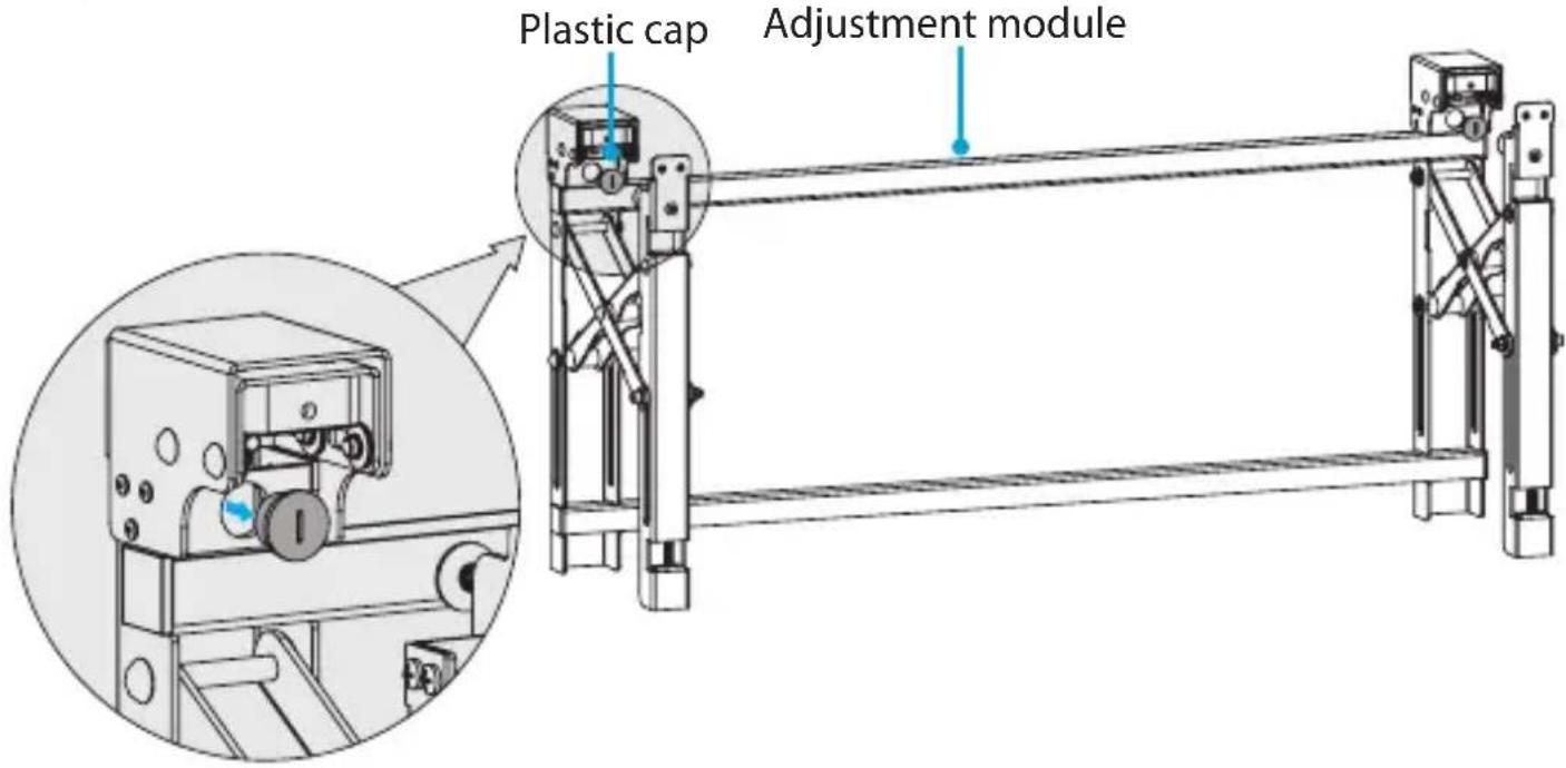
- Remove the zipped ties from around the adjustment module.
- Push on the front of the adjustment module to expand it.
- Remove and discard the two plastic caps from the top of the adjustment module. (figure 5)
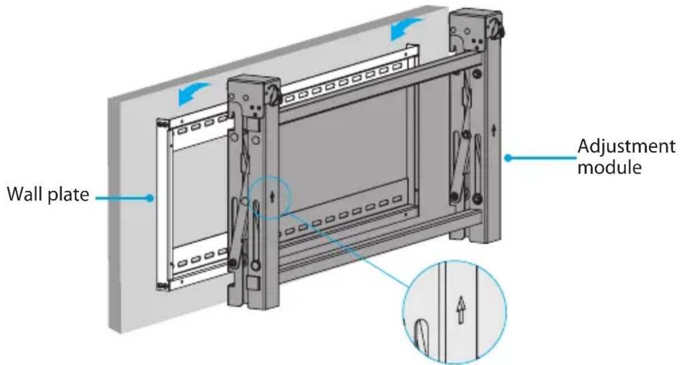
- Push on the front of the adjustment module to retract it.
- Hook the adjustment module onto the wall plate. (figure 6)
Note: Make sure that the arrows on the adjustment module are pointing upwards.
- Use a Phillips type screwdriver to tighten the two screws at the bottom of the adjustment module. (figure 7)
figure 5
Attach the adapter brackets to the TV
figure 6
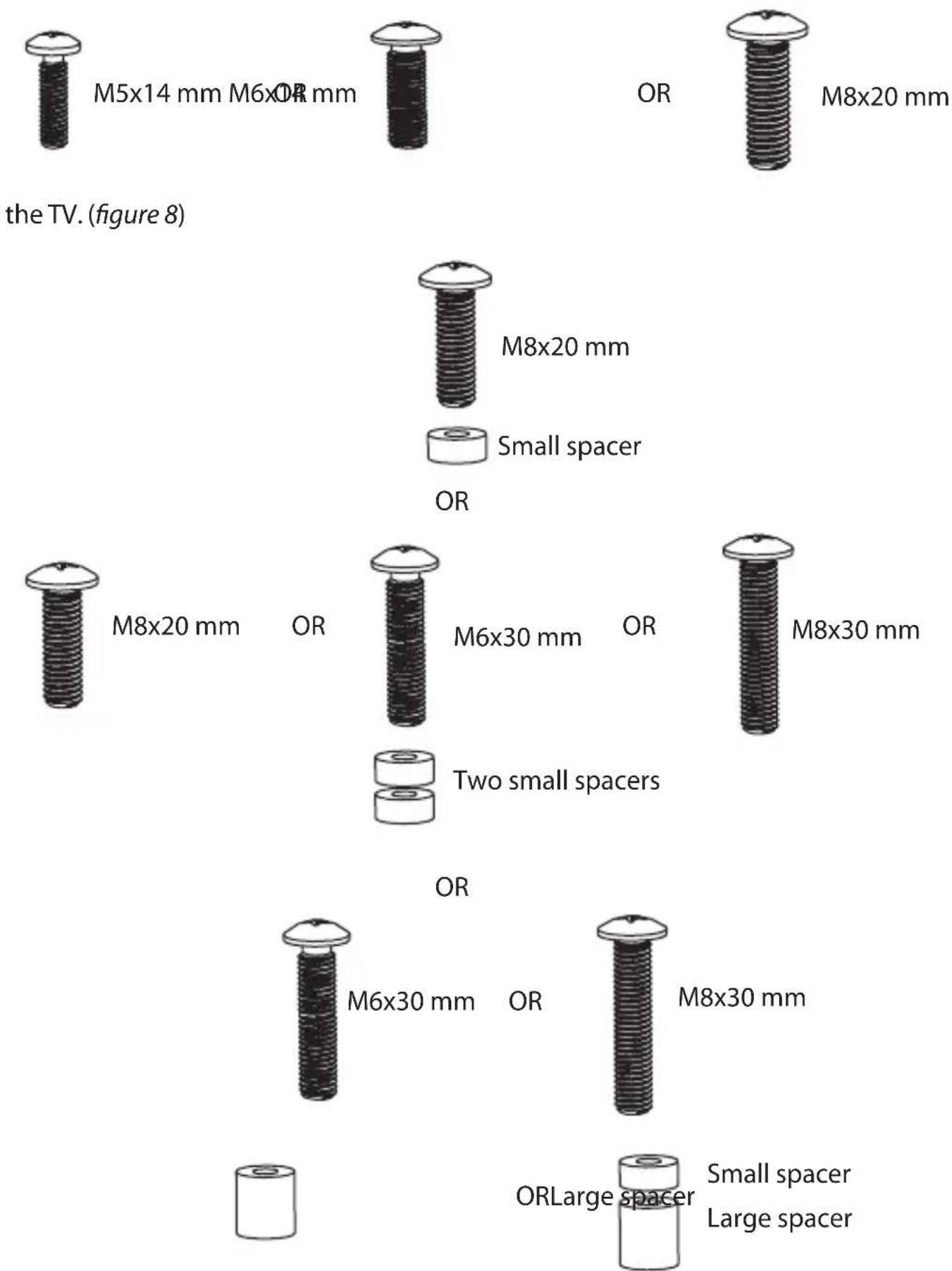
- Determine if the back of the TV is flush or inset and measure the depth and
figure 7
diameter of the mounting holes on the TV.
- With the information you obtain in step 1, consult the diagrams on the next page to determine the best configuration of the mounting hardware for the TV that you're using.
The following screw sizes work with a flush mounting surface:
The following hardware combinations work with an inset mounting surface:
-
If required, place spacers over the mounting holes on the back of the TV.
-
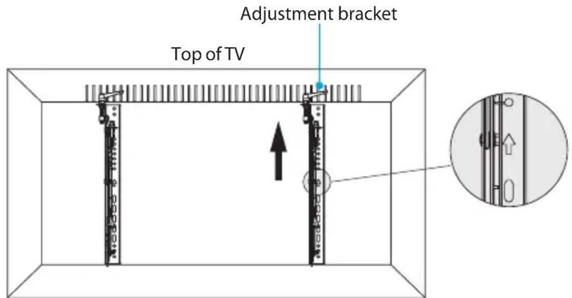
Position the adapter brackets over the spacers or the mounting holes in the back of
Note: Make sure that the arrows on the adapter brackets are pointing towards the top of the TV.
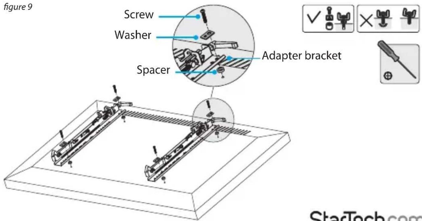
- Place the rectangular washers over the adapter brackets.
- Insert the screws through the rectangular washers, adapter brackets, spacers (if required), and into the back of the TV. (figure 9)
figure 8
- Use a Phillips type screwdriver to tighten the screws.
Warning! Do not over-tighten the screws. If you encounter resistance while you're tightening the screws, stop tightening.
Attach the TV to the adjustment module
Note: It may require two people to attach the TV assembly to the adjustment module.
Instruction manual
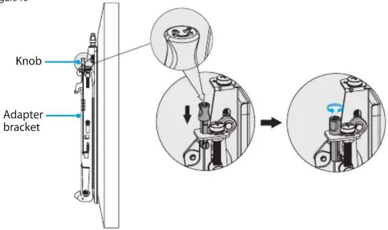
- At the top of each of the adapter brackets, push the knobs down and turn them counterclockwise to the unlocked position. (figure 10)
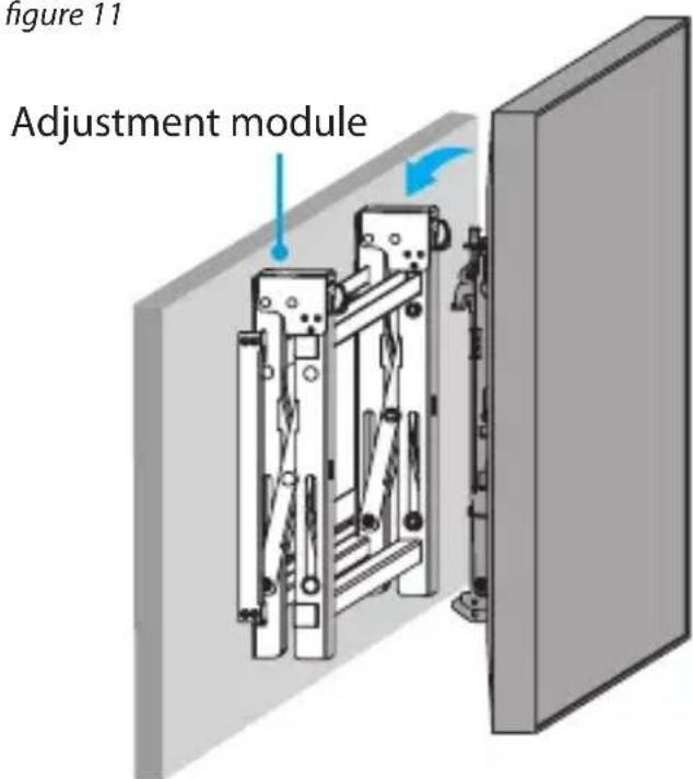
- Carefully hook the adapter brackets onto the adjustment module. (figure 11)
- At the top of each of the adapter brackets, push the knobs down and turn them clockwise to the locked position.
figure 10
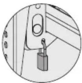
- To prevent someone from removing the TV, attach a padlock to the bottom of one
figure 11
of the adapter brackets (padlock not provided). (figure 12)
Pop a TV out from the wall
The VIDWALLMNT includes a pop-out feature that you can use to access and adjust the
figure 12
natural_image
Simple line drawing of a door handle with a lock attached (no text or symbols)mounted TVs.
- Carefully push the TV in towards the wall. (figure 13)
To retract the TV, carefully push the TV towards the wall again.
Use the kickstand
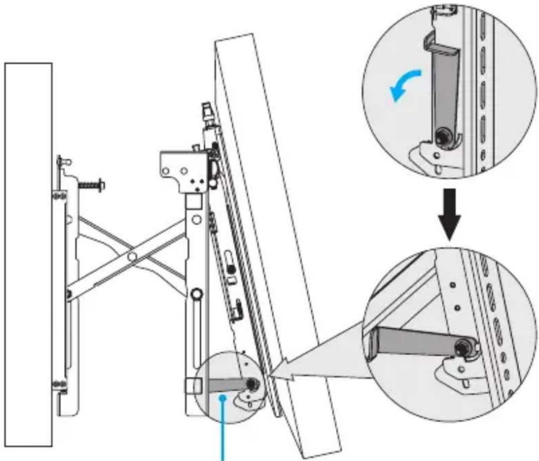
The VIDWALLMNT includes a kickstand feature that you can use when the TV is popped out from the wall to angle and access the back of the mounted TV.
figure 13
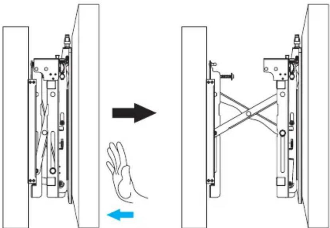
- Carefully push the TV in towards the wall to pop it out.
- Pull the bottom of the TV away from the wall and pull the kickstand down. (figure 14)
Lock the TV against the wall
figure 14
natural_image
Technical diagram of a mechanical assembly with exploded and assembled views, showing structural components and motion indicators (no text or symbols)Kickstand
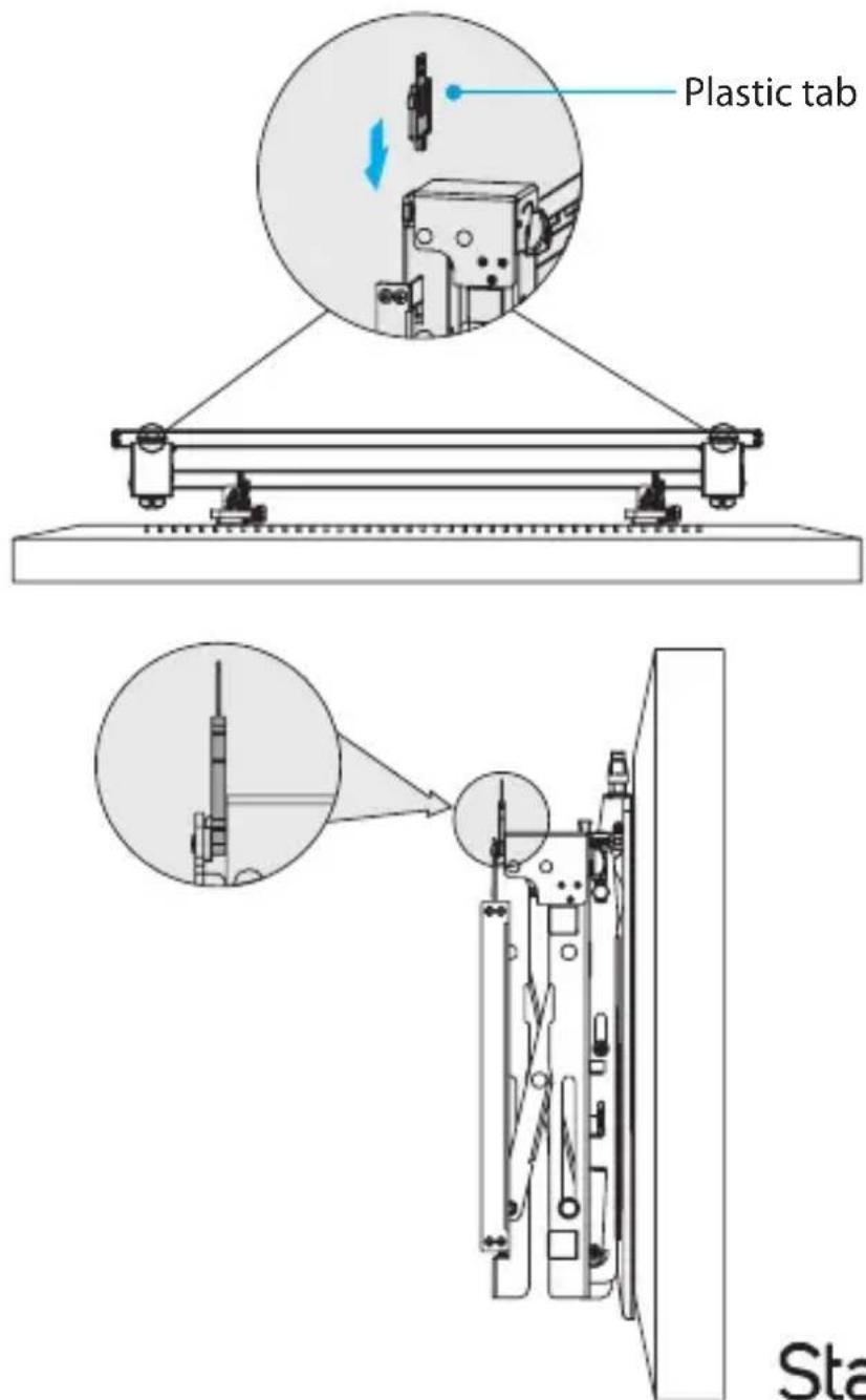
If you want to lock the TV and prevent people from being able to pop it out from the wall, complete the following:
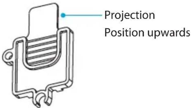
- Position the plastic tabs so that the projections are facing upwards (see the image for reference). (figure 15)
- At one end of the wall plate, insert one of the plastic tabs into the slot in the adjustment module.
- At the other end of the wall plate, repeat step 2 with the other plastic tab. (figure 16)
figure 15
Adjusting the position of the TV
You can adjust the tilt, horizontal position, vertical position, depth, and swivel of the TV.
figure 16
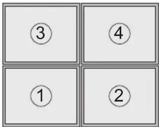
Warning! If you're adjusting a TV that is part of a multi-unit display, you need to adjust the TVs in a specific order. Starting on the lowest row of TVs, adjust the TV on the far left and move right. When the lowest row has been adjusted, move up a row and adjust the TVs from left to right. Keep moving up a row until all of the TVs have been adjusted. (figure 17)
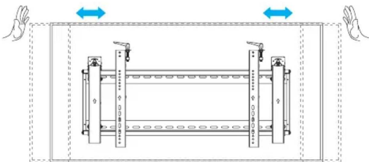
Adjust the horizontal position of the TV
- If necessary, pop the TV out from the wall.
figure 17
- Move the TV right or left until it's in the desired position. (figure 18)
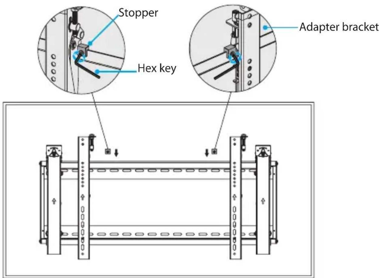
Lock the horizontal position of the TV
figure 18
natural_image
Technical diagram of a mechanical assembly with two vertical components and directional arrows indicating movement (no text or symbols)- If necessary, pop the TV out from the wall.
- Position the stoppers so that the screws are facing towards the TV.
- Slide the stoppers onto the adjustment module, placing them right next to the adapter brackets.
- Use the hex key to tighten the screws in both of the stoppers. (figure 19)
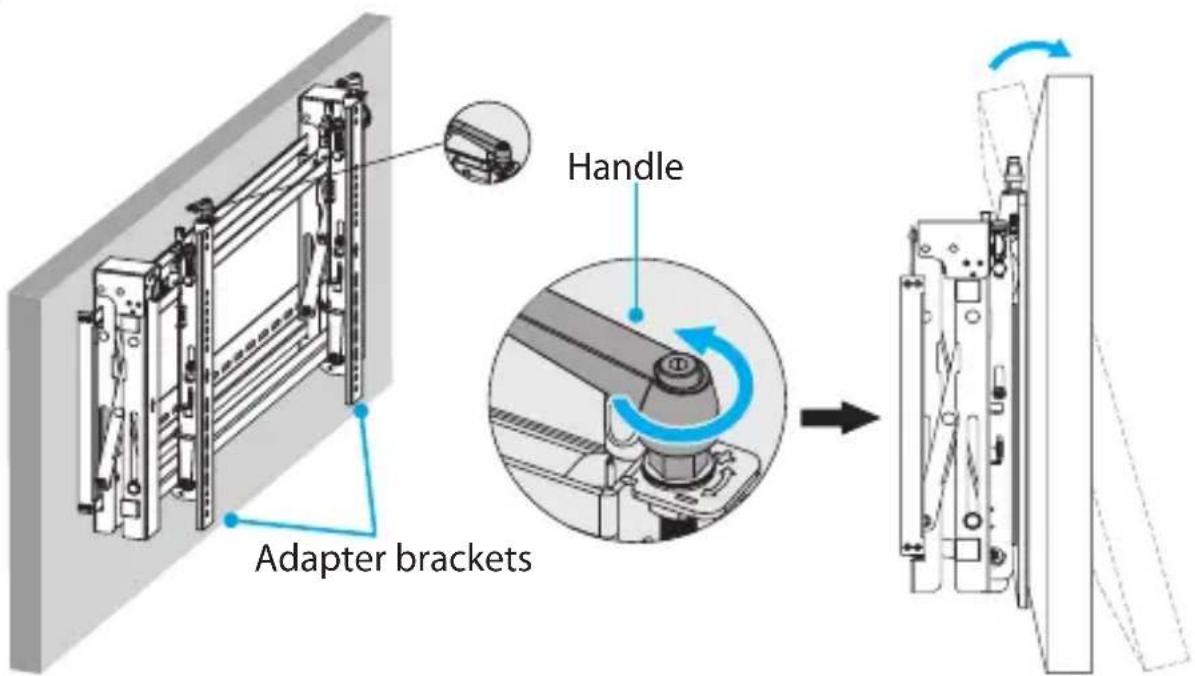
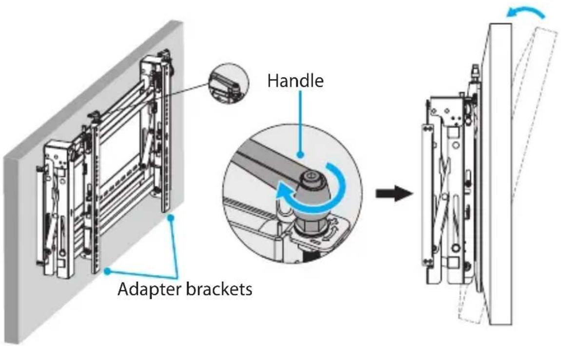
Adjust the tilt angle of the TV
figure 19
- If necessary, pop the TV out from the wall.
- Do one of the following:
• To angle the TV upwards, push the handles at the top of each of the adapter brackets down, and then turn the handles counterclockwise. (figure 20)
• To angle the TV downwards, push the handles at the top of each of the adapter brackets down, and then turn the handles clockwise. (figure 21)
figure 20
Adjust the vertical position of the TV
figure 21
- If necessary, pop the TV out from the wall.
- Do one of the following:
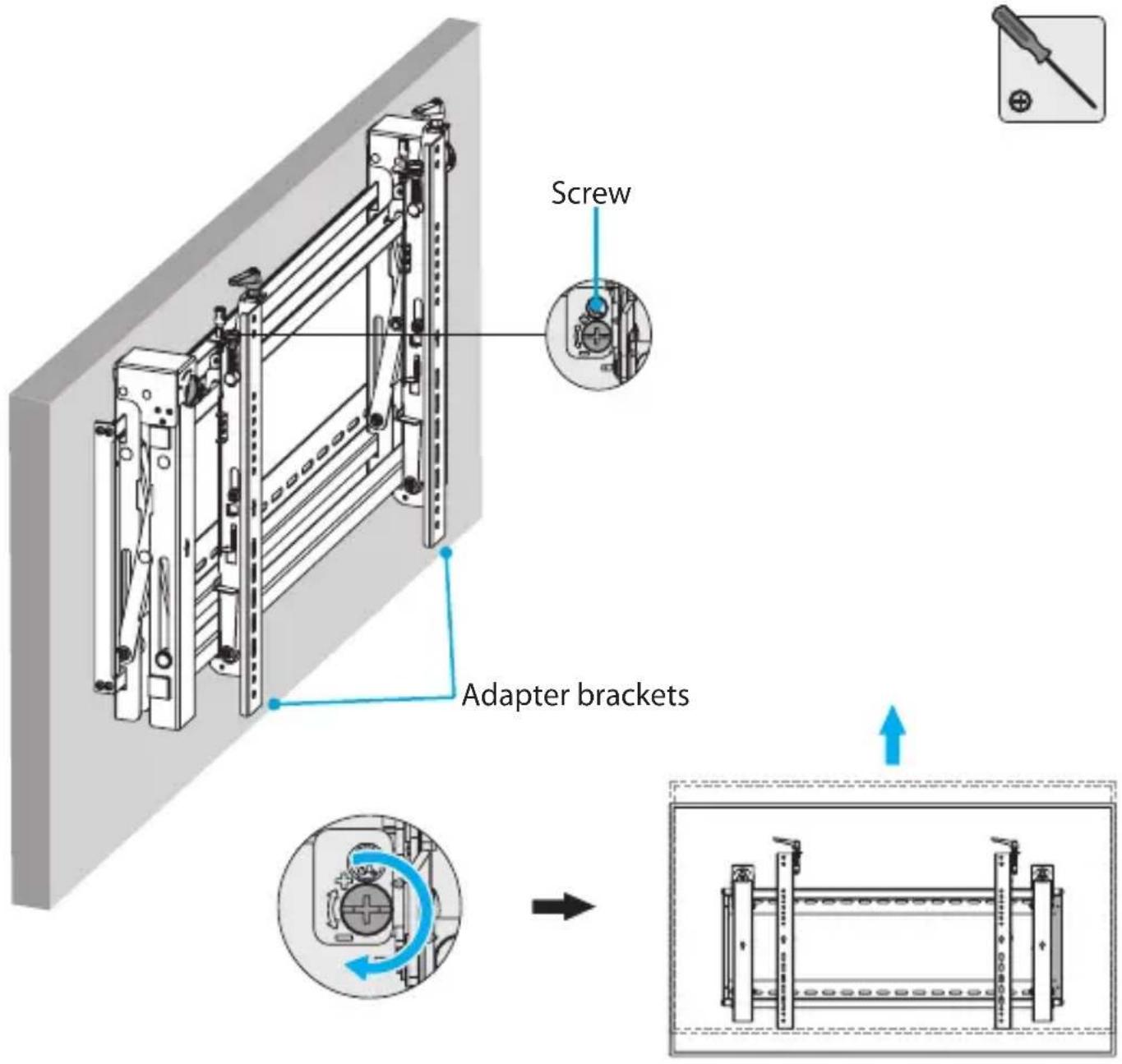
• To move the TV upwards, use a Phillips type screwdriver and turn the screws at the top of the adapter brackets clockwise. (figure 22)
• To move the TV downwards, use a Phillips type screwdriver and turn the screws at the top of the adapter brackets counterclockwise. (figure 23)
figure 22
Make the TV level
figure 23

- If necessary, pop the TV out from the wall.
- Do one of the following:
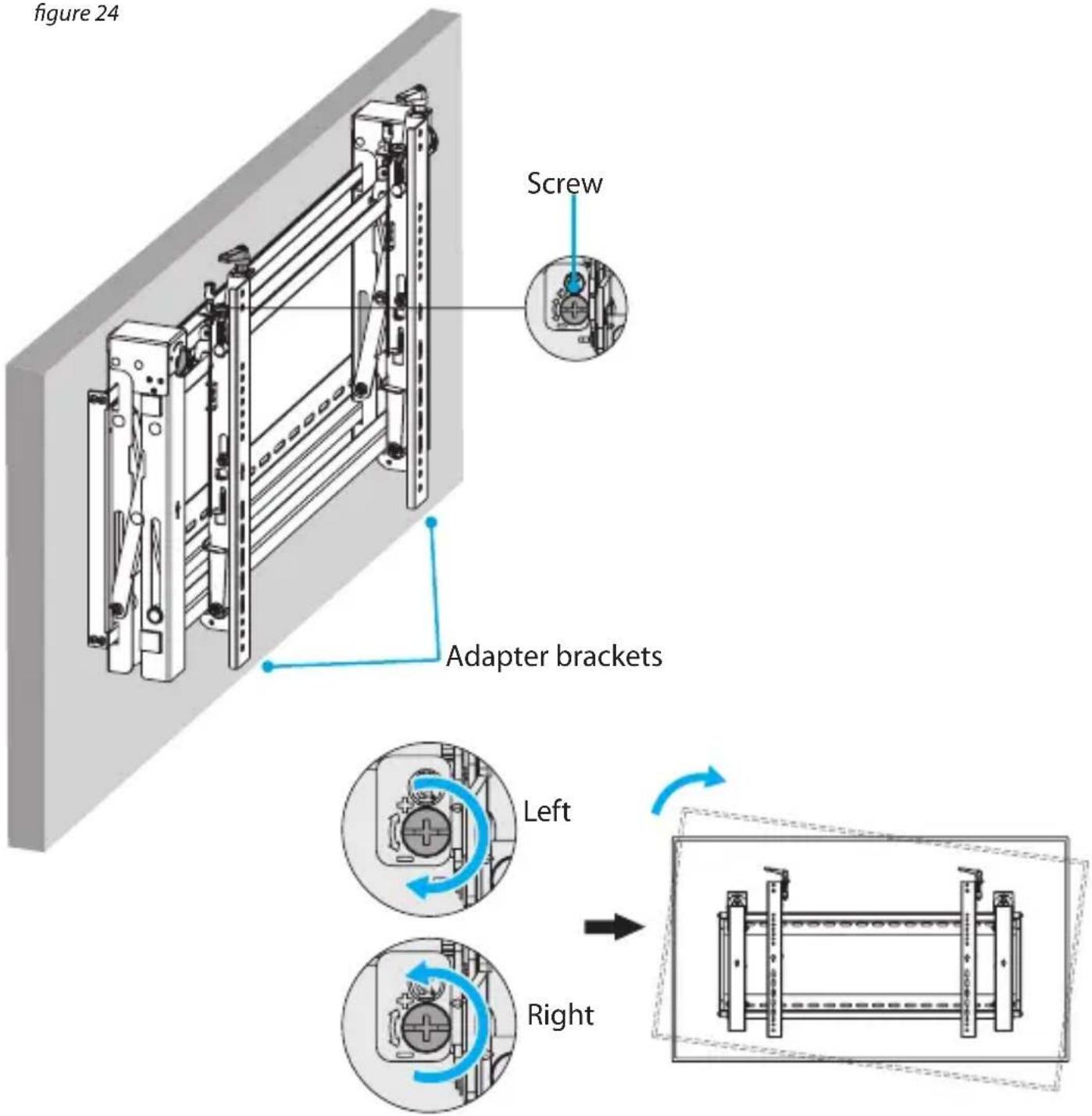
• To move the left side of the TV upwards, use a Phillips type screwdriver and turn the screw at the top of the left adapter bracket clockwise, and the screw at the top of the right adapter bracket counterclockwise. (figure 24)
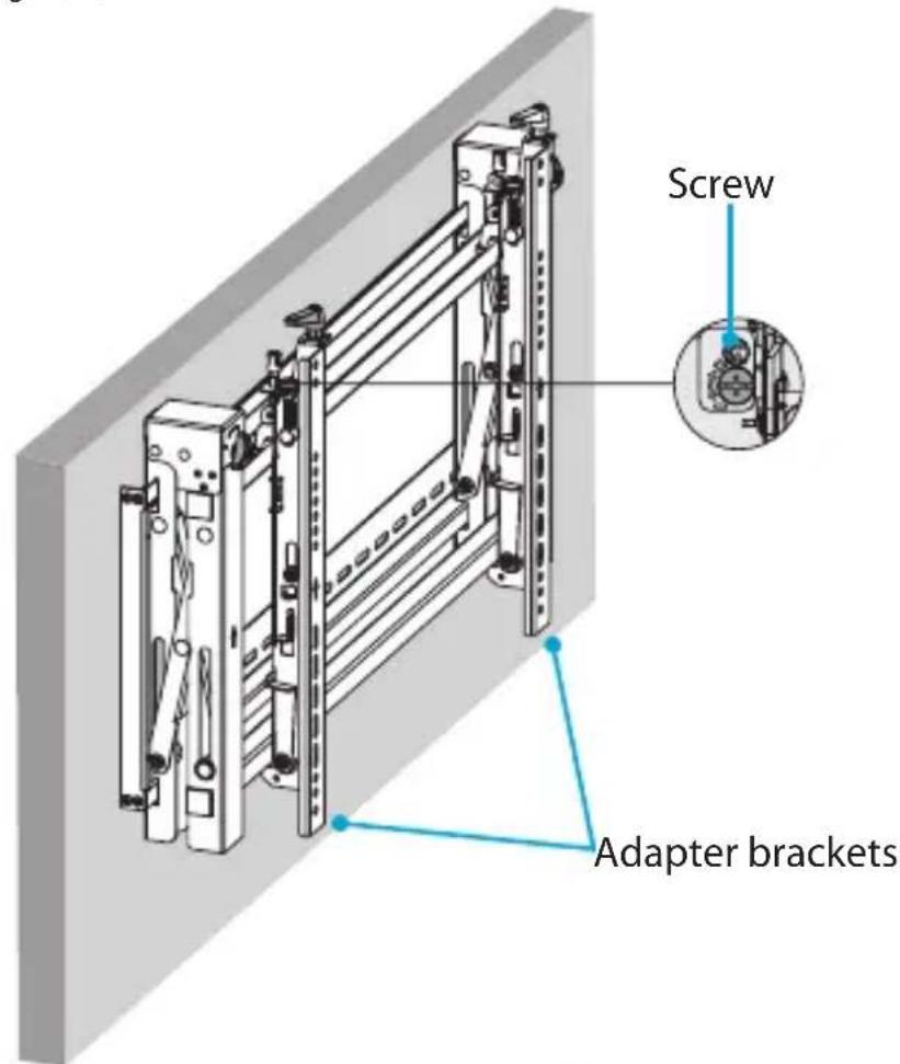
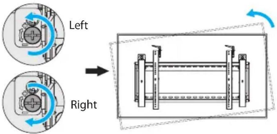
• To move the right side of the TV upwards, use a Phillips type screwdriver and
figure 24
turn the screw at the top of the left adapter bracket counterclockwise, and the screw at the top of the right adapter bracket clockwise. (figure 25)
figure 25
Adjust the depth of the TV
- If necessary, pop the TV out from the wall.
- Do one of the following:
• To move the TV away from the wall, turn the knobs on either side of the adjustment module counterclockwise. (figure 26)
figure 26
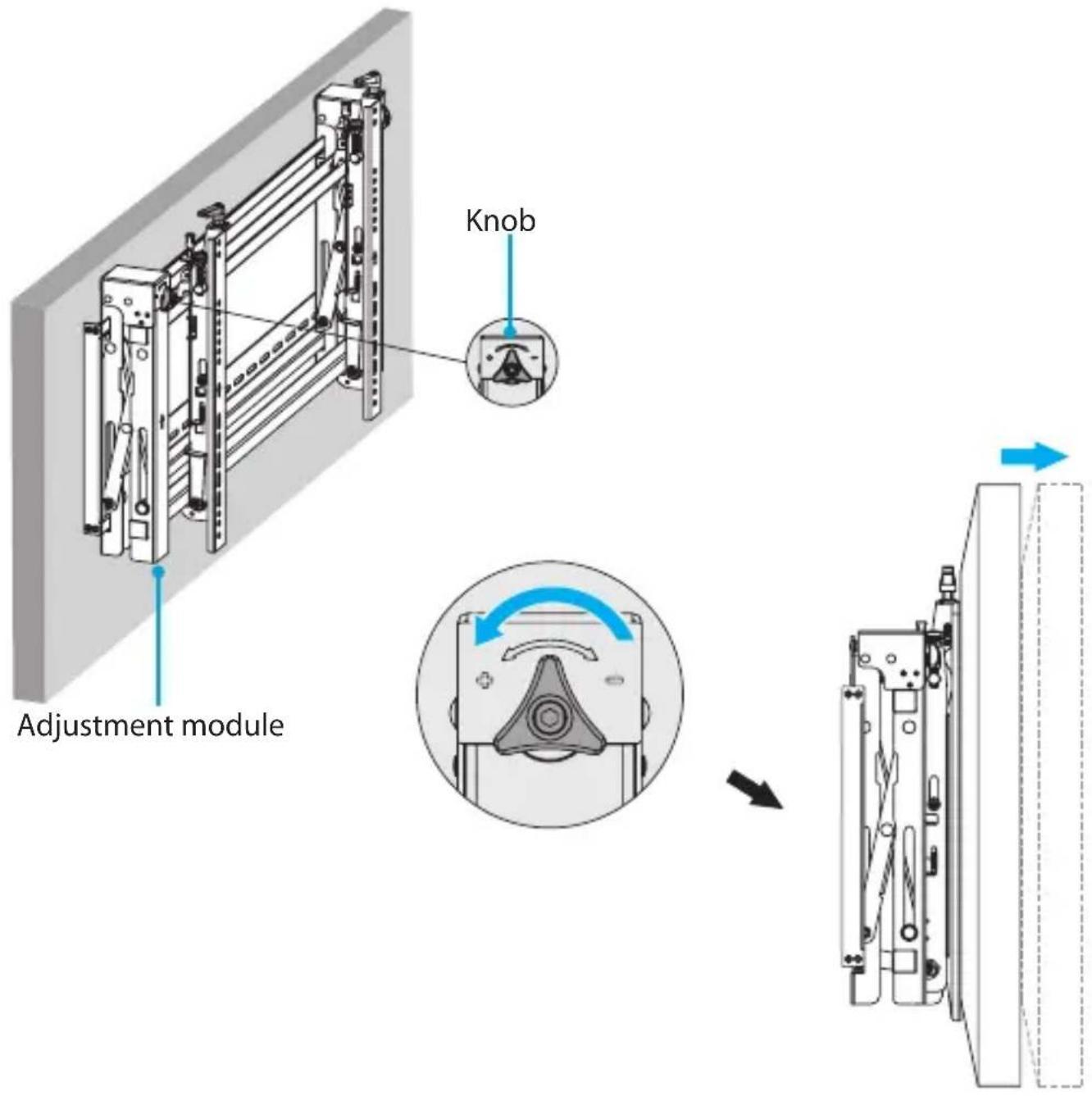
- To move the TV towards the wall, turn the knobs on either side of the adjustment module clockwise. (figure 27)
figure 27
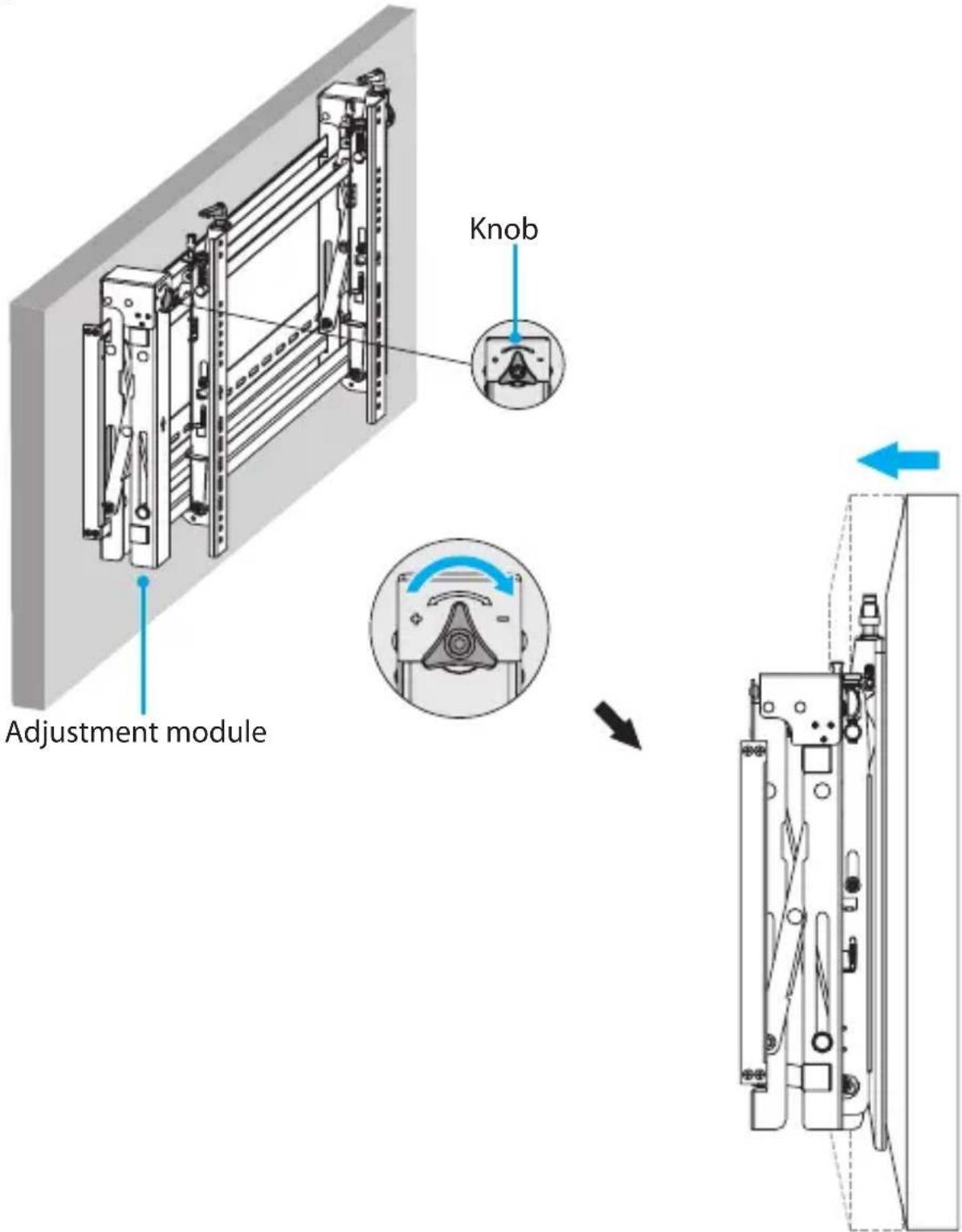
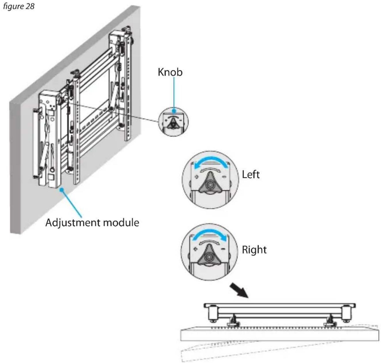
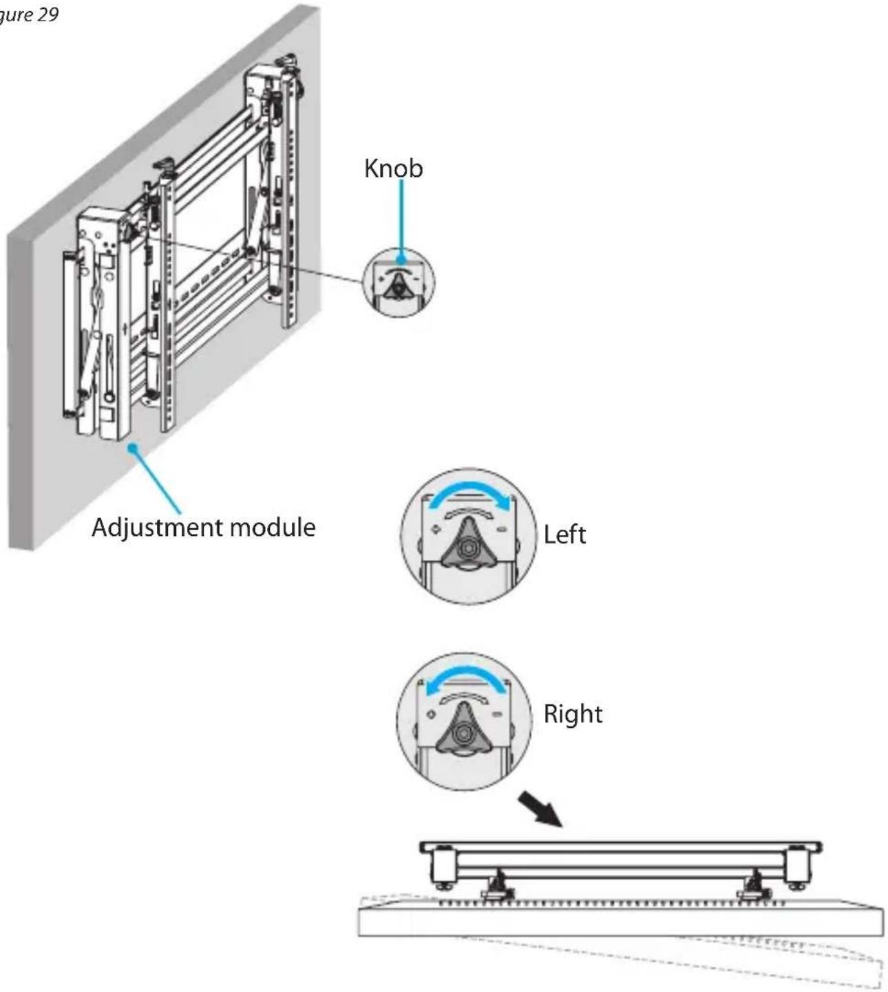
Adjust the swivel angle of the TV
- If necessary, pop the TV out from the wall.
- Do one of the following:
- To move the left side of the TV away from the wall, turn the knob on the left side of the adjustment module counterclockwise, and the knob on the right side of the adjustment module clockwise. (figure 28)
- To move the right side of the TV away from the wall, turn the knob on the left side of the adjustment module clockwise, and the knob on the right side of the adjustment module counterclockwise. (figure 29)
figure 29
Adjust the gap between the TVs
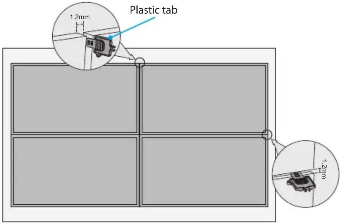
Warning! To have the clearance to pop TVs out from the wall and to accommodate any expansion of the TVs, you need to make sure that there is a 1.2 mm gap between all of the TVs. Failure to do so could result in damage to the TVs.
- Make sure that all of the TVs are level, and if they aren't, adjust the vertical and horizontal position of the TVs. For more information about how to make the adjustments, see the "Make the TV level" section of the manual.
- Insert one of the plastic tabs between the TVs and run the tab the width and height of the TVs. (figure 30)
- If there isn't enough space to run the plastic tab along the TVs, adjust the vertical and horizontal position of the TVs until there is enough space for the plastic tab to move between the TVs.
- Repeat steps 2 and 3 until the gaps between all of the TVs have been adjusted.
figure 30
Technical support
StarTech.com's lifetime technical support is an integral part of our commitment to provide industry-leading solutions. If you ever need help with your product, visit www.startech.com/support and access our comprehensive selection of online tools, documentation, and downloads.
For the latest drivers/software, please visit www.startech.com/downloads
Warranty information
This product is backed by a five-year warranty.
StarTech.com warrants its products against defects in materials and workmanship for the periods noted, following the initial date of purchase. During this period, the products may be returned for repair, or replacement with equivalent products at our discretion. The warranty covers parts and labor costs only. StarTech.com does not warrant its products from defects or damages arising from misuse, abuse, alteration, or normal wear and tear.
Limitation of Liability
In no event shall the liability of StarTech.com Ltd. and StarTech.com USA LLP (or their officers, directors, employees or agents) for any damages (whether direct or indirect, special, punitive, incidental, consequential, or otherwise), loss of profits, loss of business, or any pecuniary loss, arising out of or related to the use of the product exceed the actual price paid for the product. Some states do not allow the exclusion or limitation of incidental or consequential damages. If such laws apply, the limitations or exclusions contained in this statement may not apply to you.
Hard-to-find made easy. At StarTech.com, that isn't a slogan. It's a promise.
StarTech.com is your one-stop source for every connectivity part you need. From the latest technology to legacy products — and all the parts that bridge the old and new — we can help you find the parts that connect your solutions.
We make it easy to locate the parts, and we quickly deliver them wherever they need to go. Just talk to one of our tech advisors or visit our website. You'll be connected to the products you need in no time.
Visit www.startech.com for complete information on all StarTech.com products and to access exclusive resources and time-saving tools.
StarTech.com is an ISO 9001 Registered manufacturer of connectivity and technology parts. StarTech.com was founded in 1985 and has operations in the United States, Canada, the United Kingdom and Taiwan servicing a worldwide market.
Reviews
Share your experiences using StarTech.com products, including product applications and setup, what you love about the products, and areas for improvement.
StarTech.com Ltd.
45 Artisans
Crescent
London, Ontario
N5V 5E9
Canada
StarTech.com LLP
4490 South
Hamilton Road
Groveport, Ohio
43125
U.S.A.
StarTech.com Ltd.
Unit B, Pinnacle 15
Gowerton Road
Brackmills,
Northampton
NN4 7BW
United Kingdom
StarTech.com Ltd.
Siriusdreef 17-27
2132 WT
Hoofddorp
The Netherlands
FR: fr.startech.com
DE: de.startech.com
ES: es.startech.com
NL: nl.startech.com
IT: it.startech.com
JP: jp.startech.com
To view manuals, videos, drivers, downloads, technical drawings, and more visit www.startech.com/support
- Use of Trademarks, Registered Trademarks, and other Protected Names and Symbols
- Warning statements
- Varningsmeddelanden
- Product dimensions
- Product diagram
- Technical specifications
- Requirements
- Package contents
- Attach the wall plate to the wall
- Attach the adjustment module
- Attach the adapter brackets to the TV
- Attach the TV to the adjustment module
- Pop a TV out from the wall
- Use the kickstand
- Lock the TV against the wall
- Adjusting the position of the TV
- Adjust the horizontal position of the TV
- Lock the horizontal position of the TV
- Adjust the tilt angle of the TV
- Adjust the vertical position of the TV
- Make the TV level
- Adjust the depth of the TV
- Adjust the swivel angle of the TV
- Adjust the gap between the TVs
- Technical support
- Warranty information
- Limitation of Liability
- Hard-to-find made easy. At StarTech.com, that isn't a slogan. It's a promise.
- Reviews
- StarTech.com Ltd.
- StarTech.com LLP
Brand : StarTech.com
Model : VIDWALLMNT
Category : Wall mount