
STHDBTRX - Audio/video extender StarTech.com - Free user manual and instructions
Find the device manual for free STHDBTRX StarTech.com in PDF.


| Product Type | HDMI over Cat5/6 Receiver |
| Model Number | STHDBTRX |
| Brand | StarTech.com |
| Video Interface | HDMI |
| Max Resolution | 1920x1200 / 1080p |
| Max Transmission Distance | 230 ft (70 m) over Cat5e/6 |
| Input Connectors | 1 x RJ-45 (Link), 1 x IR Receiver (3.5mm), 1 x IR Transmitter (3.5mm) |
| Output Connectors | 1 x HDMI Female |
| Power Connector | 1 x DC Power Jack |
| Power Adapter | Universal (NA/UK/EU/AUS) 5V DC (included) |
| LED Indicators | HDCP, Link, Mode, Power |
| IR Support | Yes, IR kit (transmitter and receiver) included |
| HDCP Support | Yes |
| Mounting | Mounting brackets included |
| Dimensions (approx.) | 4.7 x 3.1 x 1.2 in (120 x 78 x 30 mm) |
| Weight (approx.) | 0.5 lb (0.23 kg) |
| Operating Temperature | 32°F to 104°F (0°C to 40°C) |
| Storage Temperature | -4°F to 140°F (-20°C to 60°C) |
| Humidity | 5% to 90% RH (non-condensing) |
| Regulatory Compliance | FCC Class B |
| Warranty | 2 Years |
| Included Accessories | Receiver unit, mounting brackets, IR kit, universal power adapter, quick install guide |
| Maintenance | Keep clean and dry; avoid exposure to liquids and extreme temperatures |
| Safety | Use only the supplied power adapter; do not open the unit; no user-serviceable parts inside |
| Repairability | Not user-serviceable; contact StarTech.com support for issues |
Frequently Asked Questions - STHDBTRX StarTech.com
User questions about STHDBTRX StarTech.com
0 question about this device. Answer the ones you know or ask your own.
Ask a new question about this device
Download the instructions for your Audio/video extender in PDF format for free! Find your manual STHDBTRX - StarTech.com and take your electronic device back in hand. On this page are published all the documents necessary for the use of your device. STHDBTRX by StarTech.com.
USER MANUAL STHDBTRX StarTech.com
4x4 HDMI® Over Cat5 Matrix Switch – 230ft (70M) HDMI® Receiver with IR for ST424HDBT
ST424HDBT
STHDBTRX
natural_image
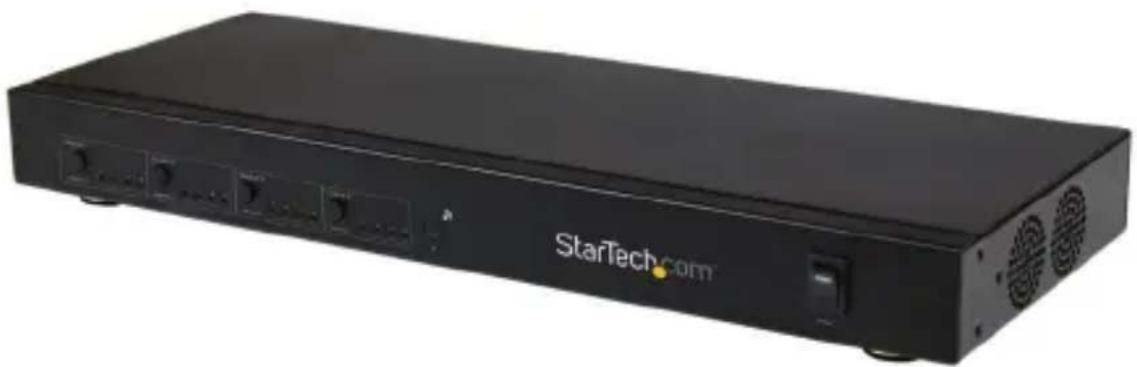
Black StarTech.com server unit with ports and ventilation slots (no readable text beyond branding)*ST424HDBT shown
For the most up-to-date information, please visit: www.startech.com
FCC Compliance Statement
This equipment has been tested and found to comply with the limits for a Class B digital device, pursuant to part 15 of the FCC Rules. These limits are designed to provide reasonable protection against harmful interference in a residential installation. This equipment generates, uses and can radiate radio frequency energy and, if not installed and used in accordance with the instructions, may cause harmful interference to radio communications. However, there is no guarantee that interference will not occur in a particular installation. If this equipment does cause harmful interference to radio or television reception, which can be determined by turning the equipment off and on, the user is encouraged to try to correct the interference by one or more of the following measures:
• Reorient or relocate the receiving antenna.
- Increase the separation between the equipment and receiver.
- Connect the equipment into an outlet on a circuit different from that to which the receiver is connected.
- Consult the dealer or an experienced radio/TV technician for help.
Use of Trademarks, Registered Trademarks, and other Protected Names and Symbols
This manual may make reference to trademarks, registered trademarks, and other protected names and/or symbols of third-party companies not related in any way to StarTech.com. Where they occur these references are for illustrative purposes only and do not represent an endorsement of a product or service by StarTech.com, or an endorsement of the product(s) to which this manual applies by the third-party company in question. Regardless of any direct acknowledgement elsewhere in the body of this document, StarTech.com hereby acknowledges that all trademarks, registered trademarks, service marks, and other protected names and/or symbols contained in this manual and related documents are the property of their respective holders.
Table of Contents
Product Diagram....1
ST424HDBT Matrix Transmitter .... 1
STHDBTRX Receiver Unit 2
Introduction....3
Packaging Contents 3
System Requirements....3
Preparing Your Site ....4
Installation 4
Hardware Installation ....4
Hardware Operation....6
Manual Matrix Operation....6
Remote Control Operation....6
RS232 Serial Operation 7
IP (Internet Protocol) Operation 21
IP Information Software Installation 24
IP Information Software Operation 24
EDID Emulation Configuration....26
What is EDID / EDID Emulation? 26
How can I determine the best EDID emulation setting for all of my displays?......26
EDID Function Table....27
Setting EDID Configuration....28
Specifications....29
Technical Support 30
Warranty Information....30
Product Diagram ST424HDBT Matrix Transmitter
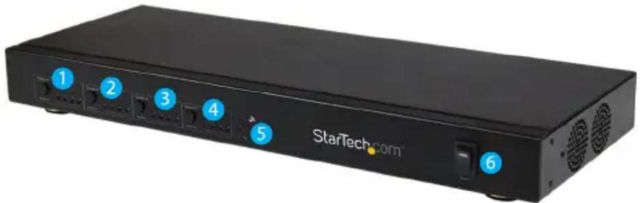
Front View
- Output 1 select button w/ LED indicator
- Output 2 select button w/ LED indicator
- Output 3 select button w/ LED indicator
- Output 4 select button w/ LED indicator
- IR sensor
- Power switch
natural_image
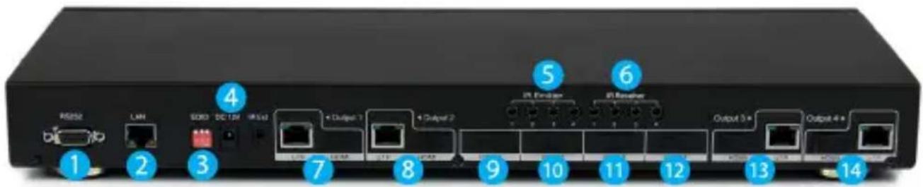
Black StarTech.com network device with six labeled ports (1–6) and a switch, no visible text beyond labels.Back View
- Serial port
- LAN port
- EDID switch
- Power Jack
- IR extender ports (1 through 4)
- IR receiver ports (1 through 4)
- Cat5/local HDMI output ports 1
- Cat5/local HDMI output ports 2
- HDMI input port 1
- HDMI input port 2
- HDMI input port 3
- HDMI input port 4
- Cat5/local HDMI output ports 3
- Cat5/local HDMI output ports 4
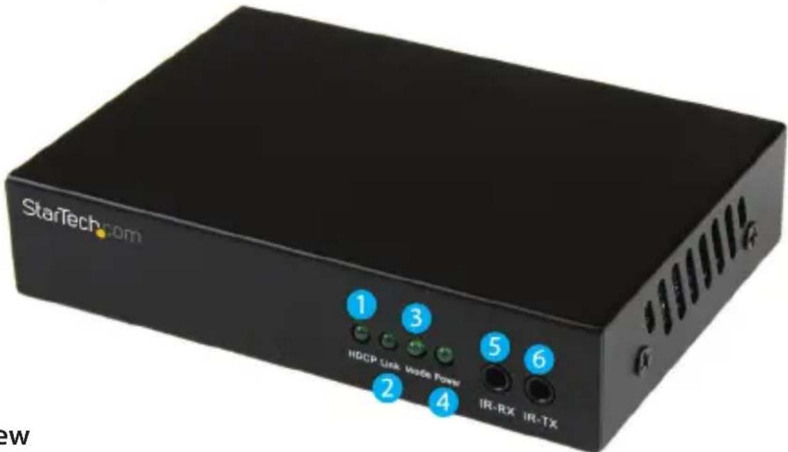
STHDBTRX Receiver Unit
Front View
- HDCP signal indicator LED
- Link LED
- Mode LED
- Power LED
- IR Receiver port
- IR Transmitter port
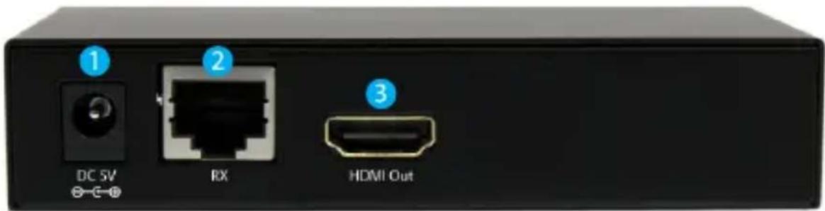
Back View
- Power jack
- Link port (RJ-45 Connector)
- HDMI out port
Introduction
Packaging Contents
ST424HDBT
• 1 x HDMI Matrix Switch
- 1 x Remote control
- 1 x Mounting brackets
• 1 x Software Installation CD
• 1 x Universal Power Adapter (NA/UK/EU/AUS)
- 1 x Quick Install Guide
STHDBTRX
• 1 x HDMI Receiver unit
- 1 x Mounting brackets
• 1 x IR kit (transmitter/receiver)
• 1 x Universal Power Adapter (NA/UK/EU/AUS)
- 1 x Quick Install Guide
System Requirements
- Up to 4 x Video source devices (i.e. computer, Blu-ray Player)
- Up to 4 x HDMI enabled display device (i.e. television, projector)
- Up to 4 x STHDBTRX HDMI Receiver units (sold separately)
- Up to 8 x M/M HDMI cables for displays and video sources (Additional cables required if using local video outputs)
Preparing Your Site
-
Determine where the local video sources (i.e. computers, Blu-ray Players) will be located and set up the device.
-
Determine where the remote displays will be located and place/ mount the displays appropriately.
Note: Please ensure the Matrix switch and each Receiver is situated near an available AC electrical outlet. Make sure all devices are turned off before beginning installation.
Installation
Hardware Installation
1. Install Matrix Transmitter
a) Position the Matrix Transmitter near the video source devices (i.e. Computers, Blu-ray Players).
b) Connect up to four HDMI cables (not included) from each of your HDMI video source devices (i.e. computers, Blu-ray Players) to each of the HDMI input ports on the matrix switch.
c) (Optional) If you intend to use local displays, connect up to 4 HDMI cables (not included) from each local HDMI output port on the matrix switch to the HDMI input ports on your local displays (i.e. televisions, projectors).
d) (Optional) If using the Extender kit to transmit an infrared (IR) device signal, and the device receiving the IR signal is on the Receiver side. Connect the IR Transmitter Cable (included with each STHDBTRX Receiver Unit) to the IR-Receiver port that corresponds with remote device that being controlled on the Matrix Unit, and position the extended IR sensor directly in front of the video source's IR sensor. Check the manual of your video source device for the IR sensor location. If the device receiving the IR signal is on the Transmitter side, then connect the IR Transmitter Cable (also included with each STHDBTRX Receiver Unit) to the IR-Transmitter port that corresponds with the remote device that is being transmitter, and position the IR sensor where the remote control will point.
e) Connect the power adapter from an available power outlet to the Power jack on the Matrix switch.
2. Install RJ45 terminated Cat5e/6 Ethernet Cable
a) Connect up to four RJ45 terminated Cat5e/6 Ethernet cables (not included) to each of the Cat5 output ports on the Transmitter unit.
Note: If you are using surface cabling, ensure you have enough Category 5e unshielded twisted pair (UTP) network cabling to connect the Matrix switch to the Receiver Unit's location, and that each end is terminated with a RJ45 connector. The cabling should not go through any networking equipment (i.e. router, switch).
OR
If you are using premises cabling, ensure that the Category 5 unshielded twisted pair (UTP) network cabling between the Host Unit and the Remote Unit has been properly terminated in a wall outlet in each location and there is a patch cable long enough to connect the Remote Unit and the Host Unit to their respective outlets. The cabling should not go through any networking equipment (i.e. router, switch).
b) Connect the other end of each Cat5e/6 cable run to the Link port (RJ-45 Connector) on the connector on the remote STHDBTRX Receiver Units (sold separately).
3. Install STHDBTRX Receiver Units (sold separately).
a) Position each Receiver Unit near the video display (i.e. television, projector).
b) Connect an HDMI cable (not included) from the Receiver unit to the video input port on the remote display device (i.e Television/Projector).
c) (Optional) If using the Matrix switch to transmit an infrared (IR) device signal, and the device receiving the IR signal is on the Transmitter side. Connect the IR Transmitter Cable to the IR-Transmitter port on the Receiver unit, and position the IR sensor where the remote control will point. If the device receiving the IR signal is on the Transmitter side, connect the IR Receiver Cable to the IR-Receiver port, and position the extended IR sensor directly in front of the video source's IR sensor. Check the manual of your video source device for the IR sensor location.
d) Connect the power adapter from an available power outlet to the power jack on the Receiver unit.
e) Repeat these steps for each STHDBTRX Receiver Unit.
-
(Optional For remote serial control) Connect a straight through DB9 serial cable (not included) from the LAN port on the back of the ST424HDBT to your network device (Router/Network Switch/PC.
-
(Optional For remote IP control) Connect a CAT5e/6 cable (not included) from the LAN port on the back of the ST424HDBT to an available COM port on your computer.
-
Hardware installation is now complete.
Hardware Operation
Manual Matrix Operation
-
Press the Output select button (that corresponds with the numbered output display) you wish to select.
-
Press the output select button repeatedly until your desired input number (that corresponds with the numbered input device) is illuminated on the LED indicator.
Remote Control Operation
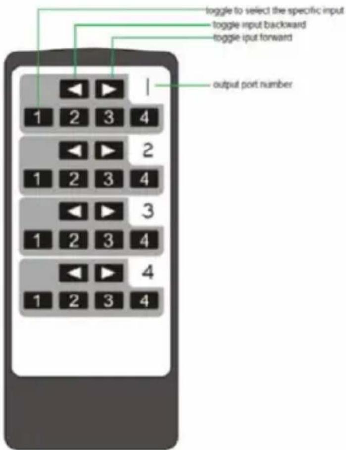
-
Each output port is represented by the number above each of the button groups. Use the group of buttons that corresponds with the numbered output display you wish to change.
-
Press the number of the input source number (that corresponds with the numbered input device) you wish to be displayed on that specific numbered output port. or
Press the left or right arrow buttons to toggle between input sources numerically, until the input number (that corresponds that corresponds with your desired input device) is displayed.
RS232 Serial Operation
Software Installation
- Download latest software from the StarTech.com website.
- Open the software folder located inside the zipped download file, run the file called COMCTL4x4-320 Vx.x.exe
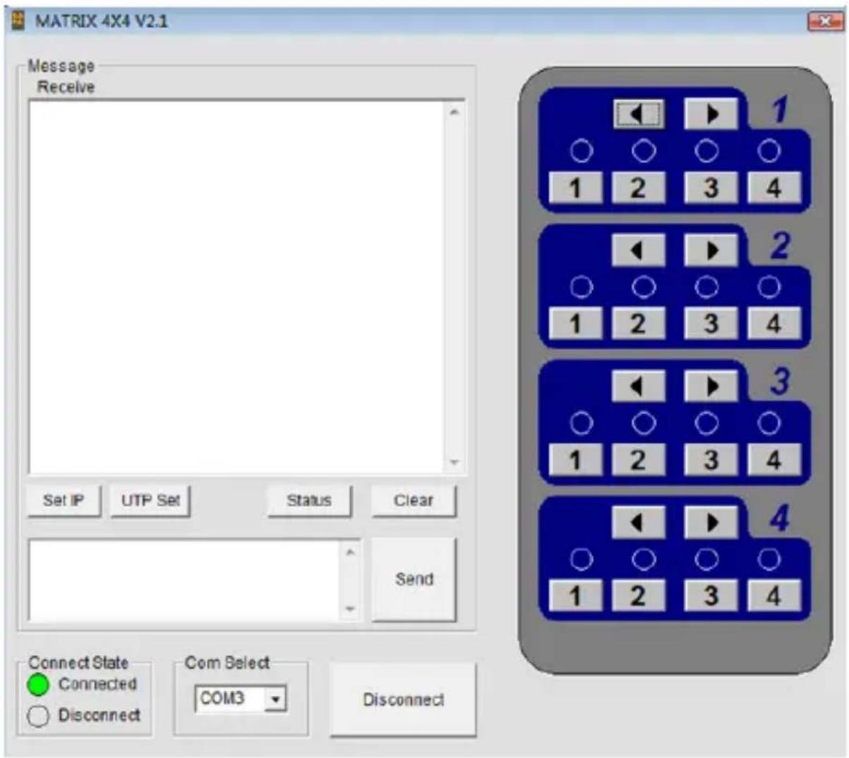
- The control interface is now displayed, with the option to connect via serial or Internet Protocol.
Software Overview and Operation
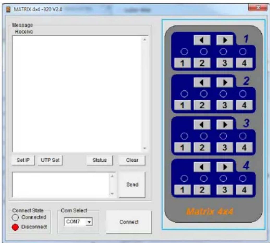
- The Message section is displayed in the top left hand corner of the software, and allows you to monitor or configure the options listed below.
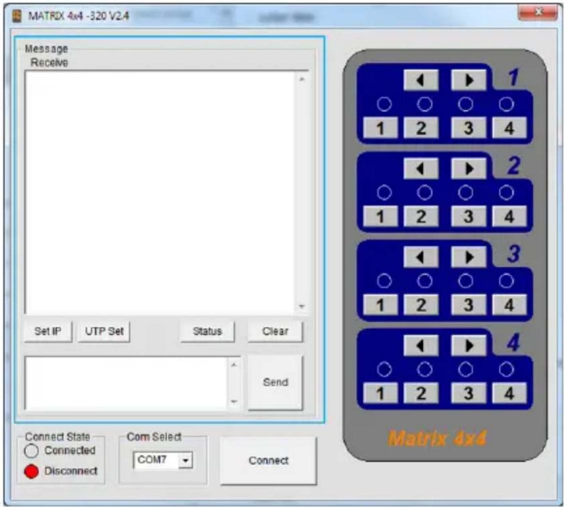
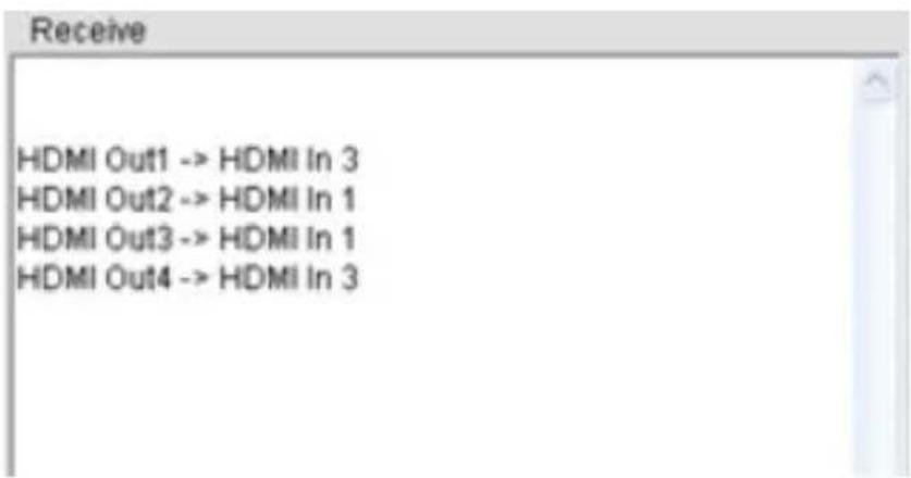
a) The Receive window is located at the top of the Message section and shows messages received from ST424HDBT.
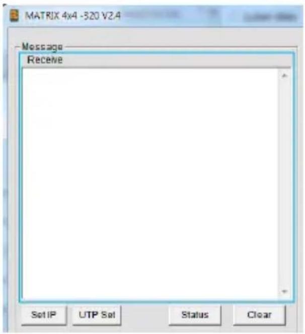
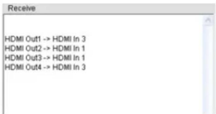
When you send a Control Command to ST424HDBT, it will display the operation results in the receive window.
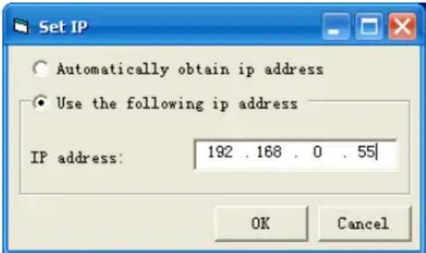
b) The set IP address button is located toward the middle left of the message section, below the Receive Window.
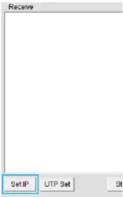
Click the button to choose whether you want your network to assign an IP address automatically using DHCP, or to define manually.
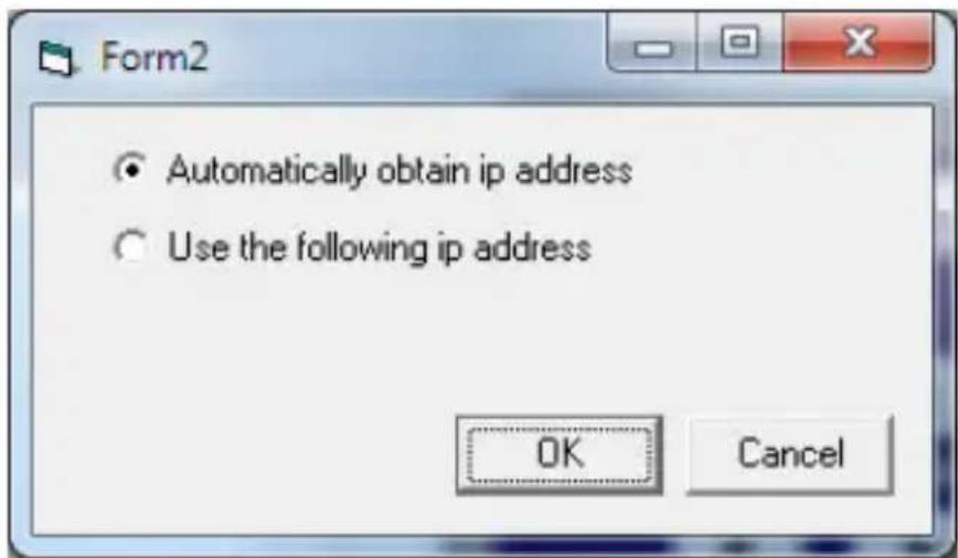
If you have chosen to manually assign your IP address click the bullet that says Use the following IP address and enter your desired IP address into the IP address: box below.
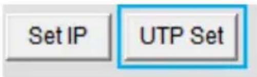
c) The UTP set button is located next to the IP address button.
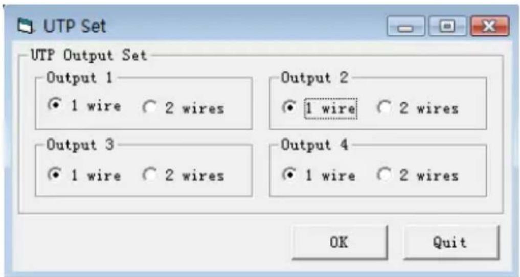
From the UTP set button you can set the four UTP output ports to single UTP mode or dual UTP mode.
d) The command box and send button is located at the bottom of the message section.
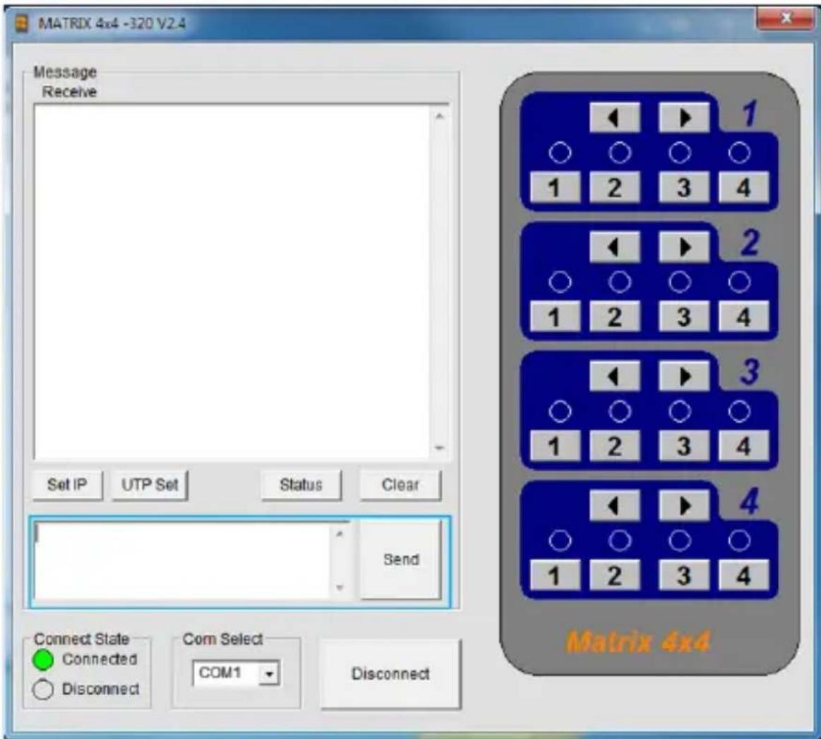
You can manually type commands in the command box using specific control codes (See Control Command Format), and click the send button to action your command.
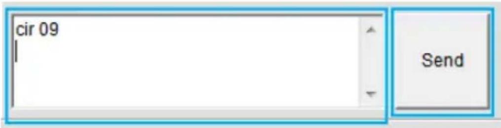
- The Com Status section is displayed at the bottom of the software, and allows you to monitor or configure the communication options listed below.
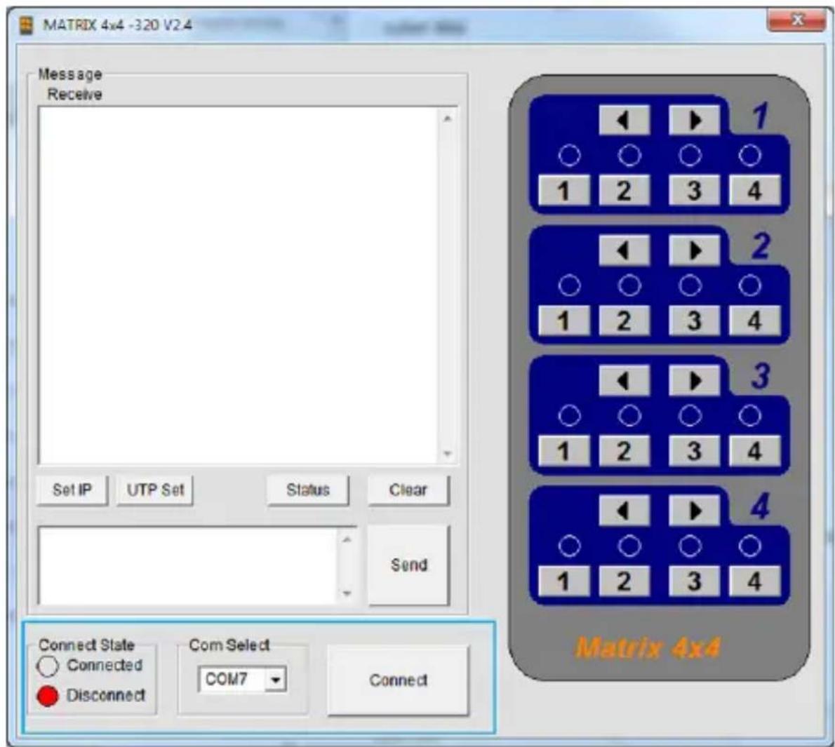
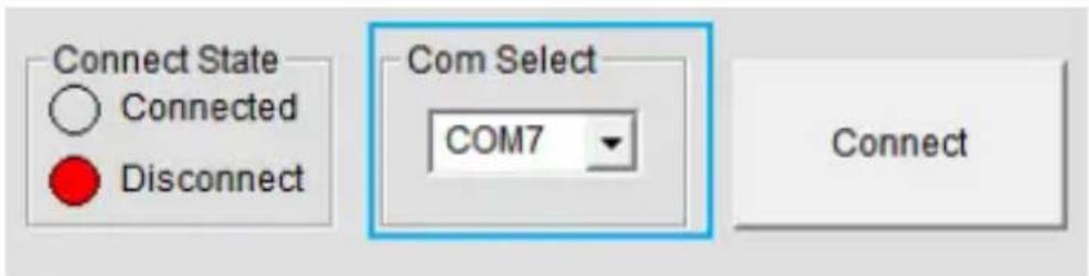
a) The Connect state is located toward the bottom left of the message section.
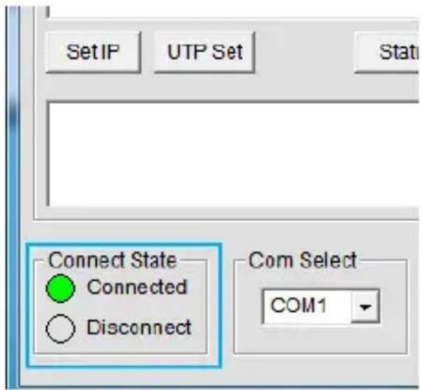
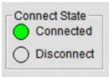
The Connection State displays whether you are connected to the ST424HDBT successfully or not, depending on which is bulleted.
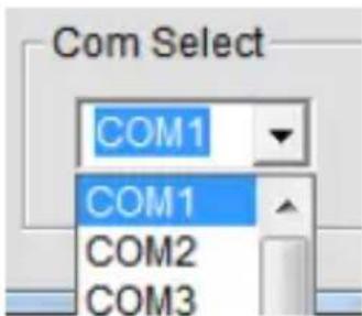
b) The Com Select drop down menu is displayed at the bottom of the software.
The Com select drop down menu enables you to select the COM port that corresponds with the serial port on your computer that the ST424HDBT is physically plugged into.
c) The Connect/Disconnect button is located at the bottom of the software.
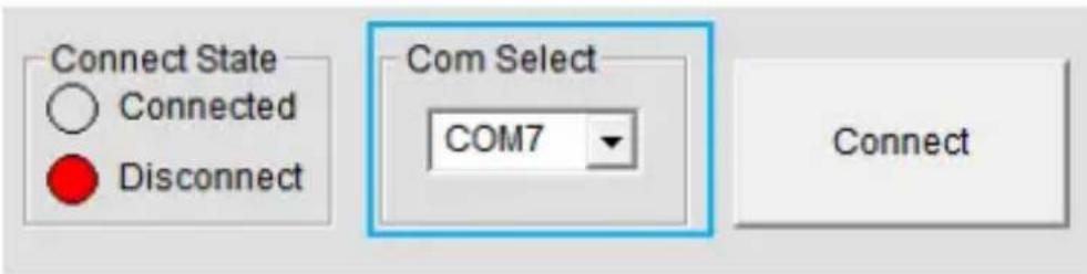
The Connect / Disconnect button enables you to connect or disconnect a com section between your computer and the ST424HDBT.
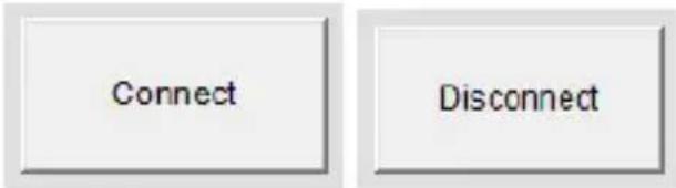
Note: If the Connection State is set to Disconnect you will have an option to Connect. If the Connection State is set to Connected you will have an option to Disconnect.
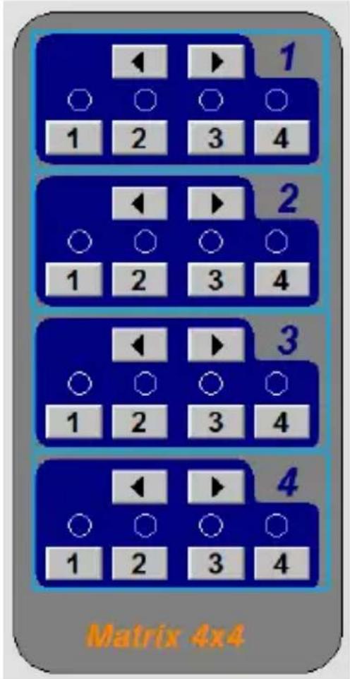
- The remote control Section is located to the right, and allows you to switch the output devices attached to the switch remotely, using the software.
a) Each output port is represented by the number above each of the button groups. Use the group of buttons that correspond with the numbered output display you wish to change.
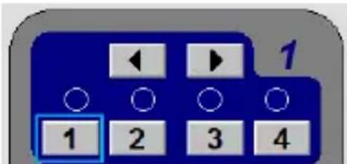
b) Press the number of the input source number (that corresponds with the numbered input device) you wish to be displayed on that specific numbered output port.
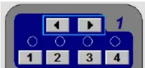
or
Press the left or right arrow buttons to toggle between input sources numerically.
c) The command that corresponds with your selection will appear on the command box in the message section, but will be actioned automatically meaning you do not need to press the Send button.
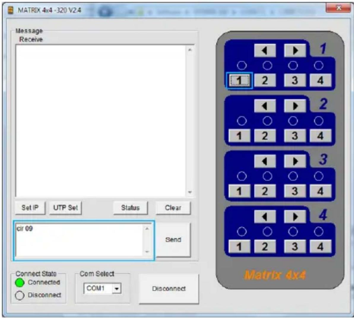
Note: the operation results will be displayed in the receive window as confirmation the operation has been completed.
Control Command Format
If you would prefer to issue commands to the ST424HDBT using third party terminal software please use the information below.
Note: Operation support for third party software is not supported by StarTech.com
Com Port Settings
| Baud Rate: 9600 bps |
| Data bits: 8 bits |
| Parity: None |
| Stop bits: 1 bit |
| Flow control: None |
Control Code
| Outport1 <“57” >“41” |
| 1“09” 2“1D” 3“1F” 4“0D” |
| Outport2 <“1B”>“11” |
| 1 “17” 2 “12” 3 “59” 4 “08” |
| Outport3 <“55”>“48” |
| 1 “5E” 2 “06” 3 “05” 4 “03” |
| Outport4 <“07”>“40” |
| 1 “18” 2 “44” 3 “0F” 4 “51” |
Command Format
$$ \operatorname{cir} + ^ {\prime} _ ^ {\prime} + \operatorname{code} + \swarrow $$
"cir" is the key word, '_' is Space, "Code" is the Control code ↩' is carriage return.
Example:
"cir 40"(hex: 63 69 72 20 34 30 0D 0A), when the mx0404 received this command, it will change the Outport4 status to the next input port. ("c"-0x63, "l"-0x69, "r"-0x72, "-0x20, "4"-0x34, "0"-0x30, (-0x0d0a)
Note: These commands can also be used in the Command box with the included software. (Software Overview and Operation.)
Hexadecimal Code List
| Command Code |
| Output1 previous: 0x63 0x69 0x72 0x20 0x35 0x37 0x0D 0x0A |
| Output1 next: 0x63 0x69 0x72 0x20 0x34 0x31 0x0D 0x0A |
| Output 1 select in1: 0x63 0x69 0x72 0x20 0x30 0x39 0x0D 0x0A |
| Output 1 select in2: 0x63 0x69 0x72 0x20 0x31 0x44 0x0D 0x0A |
| Output 1 select in3: 0x63 0x69 0x72 0x20 0x31 0x46 0x0D 0x0A |
| Output 1 select in4: 0x63 0x69 0x72 0x20 0x30 0x44 0x0D 0x0A |
| Output 2 previous: 0x63 0x69 0x72 0x20 0x31 0x42 0x0D 0x0A |
| Output 2 next: 0x63 0x69 0x72 0x20 0x31 0x31 0x0D 0x0A |
| Output 2 select in1: 0x63 0x69 0x72 0x20 0x31 0x37 0x0D 0x0A |
| Output 2 select in2: 0x63 0x69 0x72 0x20 0x31 0x32 0x0D 0x0A |
| Output 2 select in3: 0x63 0x69 0x72 0x20 0x35 0x39 0x0D 0x0A |
| Output 2 select in4: 0x63 0x69 0x72 0x20 0x30 0x38 0x0D 0x0A |
| Output3 previous: 0x63 0x69 0x72 0x20 0x35 0x35 0x0D 0x0A |
| Output3 next: 0x63 0x69 0x72 0x20 0x34 0x38 0x0D 0x0A |
| Output 3 select in1: 0x63 0x69 0x72 0x20 0x35 0x45 0x0D 0x0A |
| Output 3 select in2: 0x63 0x69 0x72 0x20 0x30 0x36 0x0D 0x0A |
| Output 3 select in3: 0x63 0x69 0x72 0x20 0x30 0x35 0x0D 0x0A |
| Output 3 select in4: 0x63 0x69 0x72 0x20 0x30 0x33 0x0D 0x0A |
| Output4 previous: 0x63 0x69 0x72 0x20 0x30 0x37 0x0D 0x0A |
Command Code
Output4 next: 0x63 0x69 0x72 0x20 0x34 0x30 0x0D 0x0A
Output 4 select in1: 0x63 0x69 0x72 0x20 0x31 0x38 0x0D 0x0A
Output 4 select in2: 0x63 0x69 0x72 0x20 0x34 0x34 0x0D 0x0A
Output 4 select in3: 0x63 0x69 0x72 0x20 0x30 0x46 0x0D 0x0A
Output 4 select in4: 0x63 0x69 0x72 0x20 0x35 0x31 0x0D 0x0A
Command Feedback Format
When a control command is received by the ST424HDBT, it will send feedback to show which input port is selected. The return status format is as follows:

flowchart
graph TD
    A["s"] --> B["1st byte"]
    A --> C["2nd byte"]
    A --> D["3rd byte"]
    E["Output"] --> C
    F["Input port(IP)"] --> D
For example, if you send "cir 09" to the ST424HDBT, once received, it will feedback "s13", meaning Output1 selects Input4.
Output to Input Return status
| OP1->IP1 "s10" |
| OP1->IP2 "s11" |
| OP1->IP3 "s12" |
| OP1->IP4 "s13" |
| OP2->IP1 "s20" |
| OP2->IP2 "s21" |
| OP2->IP3 "s22" |
| OP2->IP4 "s23" |
| OP3->IP1 "s30" |
| OP3->IP2 "s31" |
Output to Input Return status
| OP3->IP3 "s32" |
| OP3->IP4 "s33" |
| OP4->IP1 "s40" |
| OP4->IP2 "s41" |
| OP4->IP3 "s42" |
| OP4->IP4 "s43" |
Read Status Command
The command length is 4 bytes.
$$ \mathrm{bc} + ^ {\prime} - ^ {\prime} + ^ {\prime \prime} $$
"bc" is the key word, '_' is Space,'' is carriage return.
When you send the read status command to MX0404, if succeed, it will return the status of the OP(both OP1 and OP2).
Example: when you send the above command to the ST424HDBT it will feedback"s1xs2ys3zs4a", which means OP1 selects IP(x+1), OP2 selects IP(y+1), OP3 selects IP(z+1), OP4 selects IP(a+1). "s12s23s33s40" means OP1 selects IP3, OP2 selects IP4, OP3 selects IP4 and OP4 selects IP1.
Web Password Reset
The command length is 4 bytes.
$$ \mathrm{rpw} + ^ {\prime} \swarrow $$
"rpw" is the key word, √ is carriage return.
When you send the Web password reset command to ST424HDBT it will feedback "rpw" and the web password will be set as "0000000000".
IP (Internet Protocol) Operation
-
Open a web browser on a computer connected to your local network.
-
Type the IP address of the ST424HDBT into the address bar in your web browser, and press enter.
Note: If you do not know the IP address of the ST424HDBT, it can be obtained using the IP Information Software. Please see IP Information Software Installation and Operation for instructions.
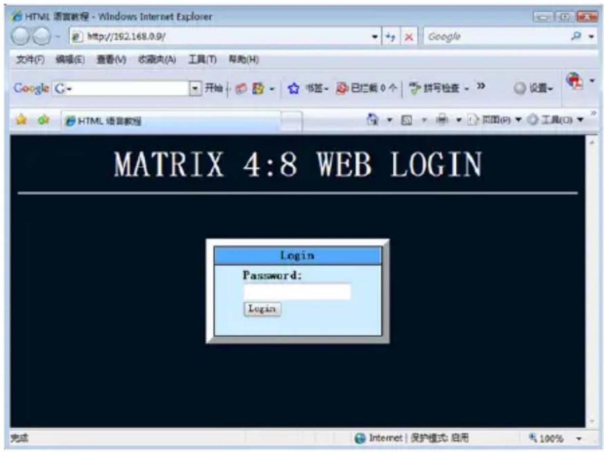
- The home page for the ST424HDBT will be displayed. Enter your password and click Login.
Note: The default password is: 0000000000
- The Web user interface is displayed. The Port Selected field on the top left displays which video Input device is currently being displayed on each video output port.
Note: The Refresh button will reload the page showing your current configuration.
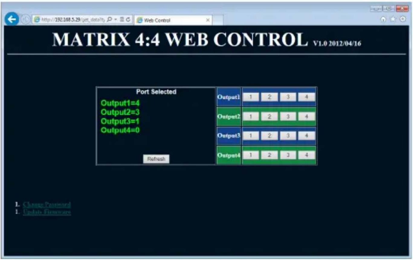
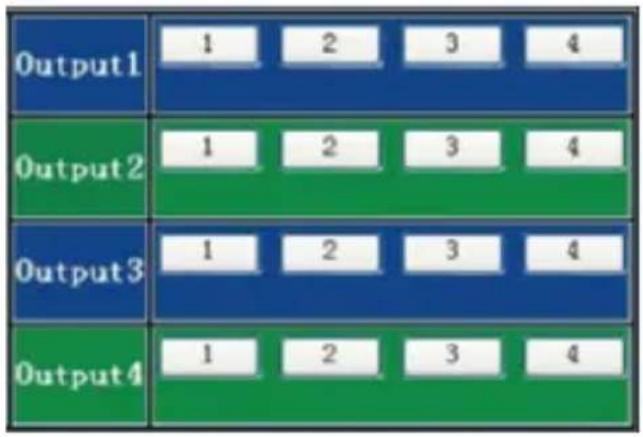
- You can change the Input device for each video output port using the output field on the top right side. Each Output port has a section with numbered buttons representing each of the video input devices. Click the number that represents the output port for your desired change.
other
| Output | Value | |---|---| | Output1 | 1 | | Output1 | 2 | | Output1 | 3 | | Output1 | 4 | | Output2 | 1 | | Output2 | 2 | | Output2 | 3 | | Output2 | 4 | | Output3 | 1 | | Output3 | 2 | | Output3 | 3 | | Output3 | 4 | | Output4 | 1 | | Output4 | 2 | | Output4 | 3 | | Output4 | 4 |-
The IR Matrix Field on the bottom left displays which IR output device is currently available for remote control at each output port.
Note: The Refresh button will reload the page showing your current configuration. -
You can change the IR Input location for each IR output port using the IR output field on the bottom right side. Each IR Output port has a section with numbered buttons representing each of the IR input locations. Click the number that represents the output port for your desired change.
| I ROUT1 | 1 | 2 | 3 | 4 |
| I ROUT2 | 1 | 2 | 3 | 4 |
| I ROUT3 | 1 | 2 | 3 | 4 |
| I ROUT4 | 1 | 2 | 3 | 4 |
IP Information Software Installation
-
Download latest software from the StarTech.com website.
-
Open the software folder located inside the zipped download file, run the file called NETCTL.exe
-
The software will open, and create a file named "NETCTL.TXT". This file contains a backup of all the device information for each device found on the network.
IP Information Software Operation
- Once the software is launched it will search your network for all attached ST424HDBT Matrix switch extenders. A list of all extenders attached to your network will be displayed. If the device is new to your network the device IP address will be listed. If the device has been seen before the software will show the device name.
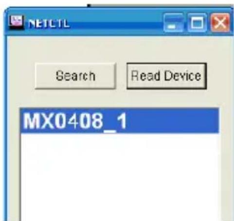
- To display the device name rather than the IP address, select the device and click the read device button.
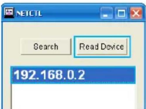
- To change the device name, right click on the device name, and select Rename from the menu.
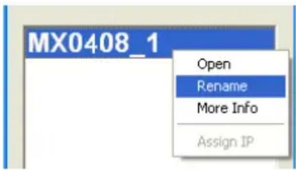
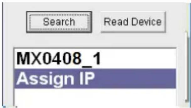
- If Assign an IP is displayed the device has not been assigned an IP address from your network. Double click Assign IP to assign an IP address.
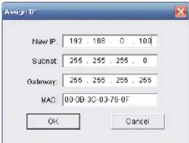
- The assign IP box will appear, enter your desired IP information and click the OK button.
- The previous window will be displayed. Click the Search button followed by the Read Device button, in order to update your device list with the new IP information.
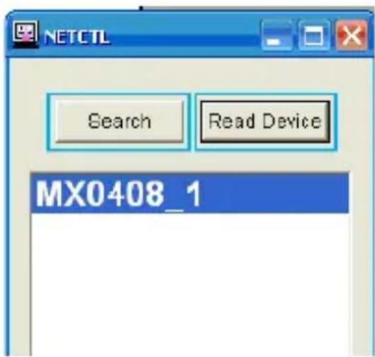
- To open the Web GUI for the ST424HDBT, double click the device name.
Note: If you have more than one ST424HDBT attached to your network, be certain to select the proper device name.
EDID Emulation Configuration
What is EDID / EDID Emulation?
EDID is a standardized protocol that allows a display to communicate its capabilities to a source device, and then allows the source to configure the video content for the display using the display's optimal video settings.
As the ST424HDBT supports multiple displays that may have different specifications (maximum resolution, audio support, etc.), the “EDID Emulation” function on the HDMI extender switch enables you to manually set an EDID signal that is ideal for all of your connected displays.
How can I determine the best EDID emulation setting for all of my displays?
Review the specifications for each of your attached display devices and find a common resolution and audio specification that each of your displays support. Once you are familiar with the specifications for each monitor and you have found a common resolution and audio specification, review the EDID Function table below to determine the best EDID Emulation function for your setup.
EDID Function Table
| EDID Emulation Setting | EDID Switch 1 | EDID Switch 2 | EDID Switch 3 | EDID Setting Details |
| EDID Copy Off Off Off | Uses the EDID settings from the display connected to your selected video output port. | |||
| 1080p (3D) Stereo Audio | Off Off On | Communicates EDID settings for a 1080p video resolution with 2-channel stereo audio and support for 3D video. | ||
| 1080p Stereo Audio | Off On Off | Communicates EDID settings for a 1080p video resolution with 2-channel stereo audio (Default Setting). | ||
| 1080i Stereo Audio | Off On On | Communicates EDID settings for a 1080i video resolution with 2-channel stereo audio. | ||
| 1080p 5.1 Surround Sound | On Off Off | Communicates EDID settings for a 1080p video resolution with 5.1-channel Surround Sound audio. | ||
| 1080p 7.1 Surround Sound | On Off On | Communicates EDID settings for a 1080p video resolution with 7.1-channel Surround Sound audio. | ||
Setting EDID Configuration
- Using the EDID Switch, set the dip switches to your desired EDID Emulation Setting as specified in the EDID Function Table.
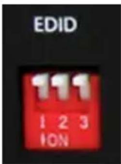
- Press and hold the Output 1 selection button for several seconds until the LED indicator flashes.
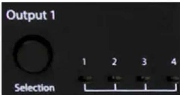
- Your desired EDID settings is now set.
Specifications
| Number of input Ports 4 | |
| Number of output Ports 8 (4x HDMI / 4x CAT5) | |
| Connectors | 4 x HDMI female (A/V input) |
| 4 x HDMI female (A/V output) | |
| 4 x RJ-45 female (A/V output) | |
| 1 x RJ-J5 female (LAN Control) | |
| 1 x DB-9 female (Serial Control) | |
| 1 x IRDA (Infrared) Female (3.5mm) | |
| 1 x DC Power | |
| LEDs | 1 x Power/Signal Input |
| 4 x Output 1 Display Selection | |
| 4x Output 2 Display Selection | |
| 4x Output 3 Display Selection | |
| 4x Output 4 Display Selection | |
| 1x Output 1 UPT Activity (rear) | |
| 1x Output 2 UPT Activity (rear) | |
| 1x Output 3 UPT Activity (rear) | |
| 1x Output 4 UPT Activity (rear) | |
| 1x LAN Activity (Rear) | |
| Max. Resolution 1920x1200 / 1080p | |
| Max. CAT5 Cable Length 230ft (70m) | |
| Audio Support Yes | |
| EDID Support Yes | |
Technical Support
StarTech.com's lifetime technical support is an integral part of our commitment to provide industry-leading solutions. If you ever need help with your product, visit www.startech.com/support and access our comprehensive selection of online tools, documentation, and downloads.
For the latest drivers/software, please visit www.startech.com/downloads
Warranty Information
This product is backed by a two year warranty.
In addition, StarTech.com warrants its products against defects in materials and workmanship for the periods noted, following the initial date of purchase. During this period, the products may be returned for repair, or replacement with equivalent products at our discretion. The warranty covers parts and labor costs only. StarTech.com does not warrant its products from defects or damages arising from misuse, abuse, alteration, or normal wear and tear.
Limitation of Liability
In no event shall the liability of StarTech.com Ltd. and StarTech.com USA LLP (or their officers, directors, employees or agents) for any damages (whether direct or indirect, special, punitive, incidental, consequential, or otherwise), loss of profits, loss of business, or any pecuniary loss, arising out of or related to the use of the product exceed the actual price paid for the product. Some states do not allow the exclusion or limitation of incidental or consequential damages. If such laws apply, the limitations or exclusions contained in this statement may not apply to you.
Hard-to-find made easy. At StarTech.com, that isn't a slogan. It's a promise.
StarTech.com is your one-stop source for every connectivity part you need. From the latest technology to legacy products — and all the parts that bridge the old and new — we can help you find the parts that connect your solutions.
We make it easy to locate the parts, and we quickly deliver them wherever they need to go. Just talk to one of our tech advisors or visit our website. You'll be connected to the products you need in no time.
Visit www.startech.com for complete information on all StarTech.com products and to access exclusive resources and time-saving tools.
StarTech.com is an ISO 9001 Registered manufacturer of connectivity and technology parts. StarTech.com was founded in 1985 and has operations in the United States, Canada, the United Kingdom and Taiwan servicing a worldwide market.

- 4x4 HDMI® Over Cat5 Matrix Switch – 230ft (70M) HDMI® Receiver with IR for ST424HDBT
- FCC Compliance Statement
- Use of Trademarks, Registered Trademarks, and other Protected Names and Symbols
- Table of Contents
- Product Diagram....1
- Introduction....3
- Preparing Your Site ....4
- Installation 4
- Hardware Operation....6
- EDID Emulation Configuration....26
- Specifications....29
- Technical Support 30
- Warranty Information....30
- Product Diagram ST424HDBT Matrix Transmitter
- Front View
- Back View
- STHDBTRX Receiver Unit
- Introduction
- Packaging Contents
- ST424HDBT
- STHDBTRX
- System Requirements
- Preparing Your Site
- Installation
- Hardware Installation
- Install Matrix Transmitter
- Install RJ45 terminated Cat5e/6 Ethernet Cable
- OR
- Install STHDBTRX Receiver Units (sold separately).
- Hardware Operation
- Manual Matrix Operation
- Remote Control Operation
- RS232 Serial Operation
- Software Installation
- Software Overview and Operation
- Control Command Format
- Command Format
- Example:
- Command Code
- Command Feedback Format
- Read Status Command
- Web Password Reset
- IP (Internet Protocol) Operation
- IP Information Software Installation
- IP Information Software Operation
- EDID Emulation Configuration
- What is EDID / EDID Emulation?
- How can I determine the best EDID emulation setting for all of my displays?
- Setting EDID Configuration
- Technical Support
- Warranty Information
- Limitation of Liability
Brand : StarTech.com
Model : STHDBTRX
Category : Audio/video extender