
NANO - Intercom CAME-TV - Free user manual and instructions
Find the device manual for free NANO CAME-TV in PDF.


| Type | Intercom |
| Brand | CAME-TV |
| Model | NANO |
| Technology | DECT, GAP compatible |
| Operating Frequency | FCC: 1920-1930 MHz; CE: 1881.792-1897.344 MHz |
| Working Distance (Master) | Up to 1100 ft (335 m) radius in open air |
| System Configuration | 1 Master + up to 4 Remotes (standard); expandable to 20 with Hubs |
| Battery Capacity | 3.7V, 1100 mAh (internal Li-ion) |
| Battery Life (Master) | 7 hours |
| Battery Life (Remote) | 13 hours |
| Charging Interface | USB Type-C, 5V 500mA |
| Charging Time | Approx 2 hours |
| Audio Interface | 3.5mm TRRS (CTIA standard) |
| Duplex Type | Full duplex (Time Division Duplex) |
| Modulation | GFSK |
| Channel Bandwidth | 1.728 MHz |
| Speaker | Built-in |
| Microphone | Built-in with mute function |
| Indicators | LED for battery level (green/yellow/red), connection status, mute |
| Dimensions (approx) | 100 x 60 x 20 mm |
| Weight (approx) | 100 g |
| Hub Compatibility | Optional Hub for expanded groups up to 20; micro USB power; NB-6L battery compartment; runtime 8-10h (1 batt) / 15-18h (2 batts) |
| Carrying Options | Belt clip, lanyard, hand-held |
| Cleaning | Wipe with dry cloth; avoid liquids |
| Safety Compliance | FCC Part 15, SAR compliant |
Frequently Asked Questions - NANO CAME-TV
User questions about NANO CAME-TV
0 question about this device. Answer the ones you know or ask your own.
Ask a new question about this device
Download the instructions for your Intercom in PDF format for free! Find your manual NANO - CAME-TV and take your electronic device back in hand. On this page are published all the documents necessary for the use of your device. NANO by CAME-TV.
USER MANUAL NANO CAME-TV
natural_image
Close-up of a black electronic device with speaker icons and control buttons (no readable text)O N A Z
USER MANUAL
V2.4.2
The CAME-NANO is a compact portable intercom device that adopts full duplex technology, allowing multiple parties to have simultaneous conversations. It features a built-in speaker on the fuselage, which can produce sound externally, and it can also be connected to other audio devices using a 3.5mm audio jack. It offers versatile carrying options, such as hanging, clipping, or holding it by hand.

Suggestions for optimal use
11 When you receive NANO, please charge it before turning it on.
② Make sure the devices are in off state while charging to prevent battery draining when fully charged.
3 When devices are in close proximity, they may generate noise. To mitigate this, press the middle button to turn off the microphone.
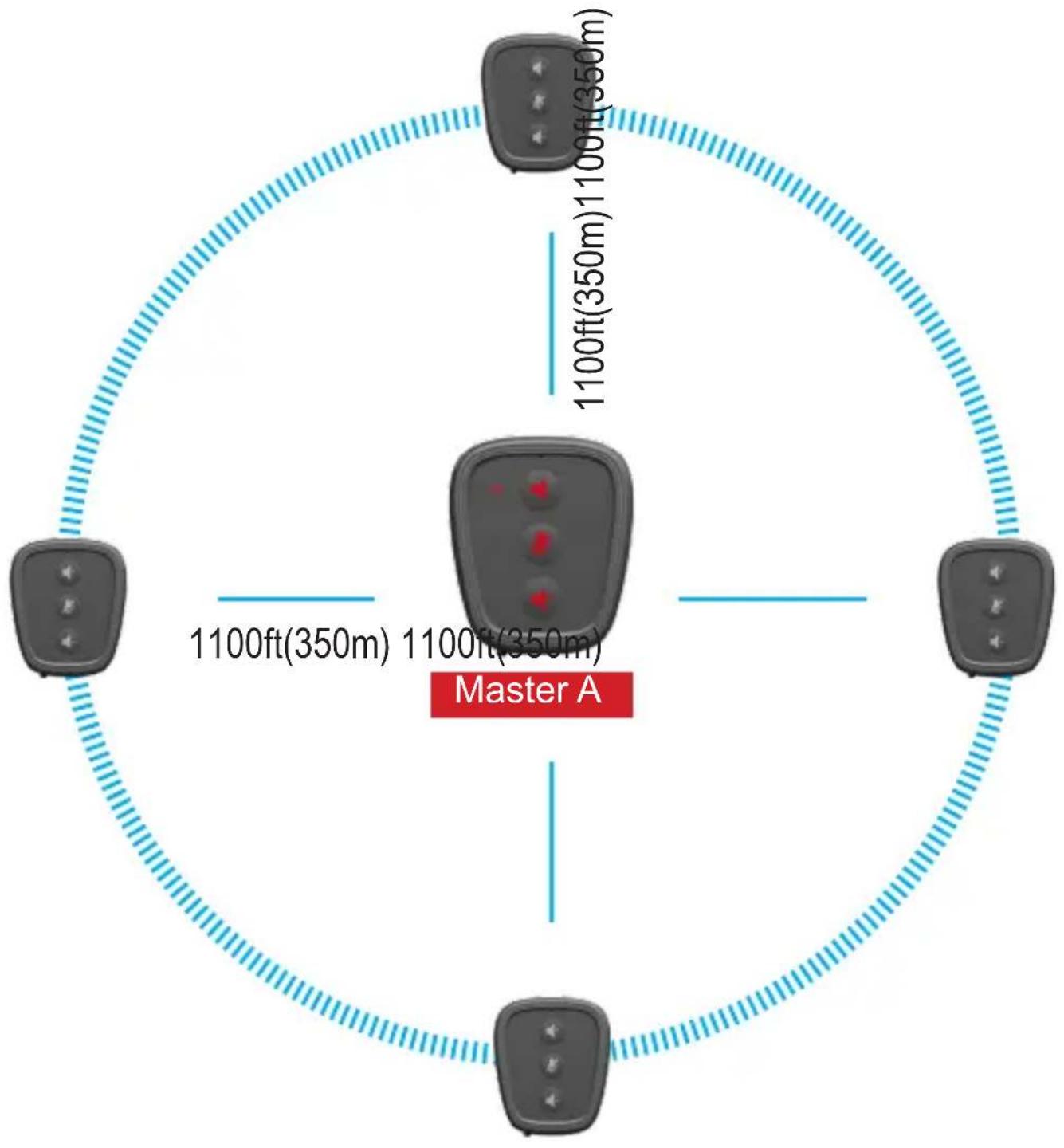
24 The intercom system consists of a master and multiple remotes. The master acts as a signal transfer station for the remotes. So in actual use, the remotes should be distributed around the master to achieve the optimal use effect.
The best communication quality is achieved when there are no obstacles between the master and remotes. Obstructions like the human body can impact the effectiveness of the device. So we advise using arm belt.
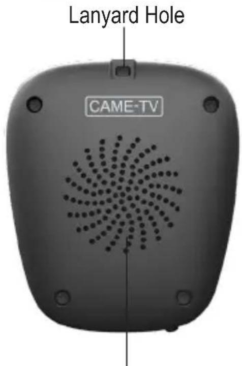
45 The signal antenna of the CAME-NANO is generally located around the lanyard hole area. It is important to not cover this region to ensure quality communication.
The 3.5mm interface follows the (US) CTIA standard. If you have OMTP standard equipment, an audio cable will be required.
| Parameters | |
| Standard DECT technology, GAP compatible | |
| Working Distance | 1100 ft. radius at Master in the open air |
| Working Time Master 7 Hours // Remote 13 Hours | |
| Channel Bandwidth 1.728MHz | |
| Modulation Type GFSK | |
| Duplex Operation Time Division Duplex (TDD) | |
| CE Frequency 1881.792-18 | 97.344 MHz |
| FCC Frequency 1920-1930 MHz | |
| Type-C Charging 5V, 500mA | |
| Battery Capacity 3.7V ,1100 mAh | |
| Audio Interface 3.5mm TRRS | |

natural_image
Line drawing of a device tray with three speaker icons (no text or symbols)CAME-NANO
Product Structure
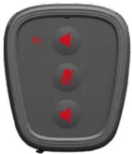
The Master buttons are in red with the letter "M", while the Remote buttons are in white without letters.
natural_image
Gray rectangular device with three red speaker icons on a dark background (no text or symbols)MASTER

natural_image
Gray rectangular device with three speaker icons on a dark background (no text or symbols)REMOTE


natural_image
Black industrial device with attached bracket and side panel (no visible text or symbols)Back Clip Speaker
| State LED Indicator | |
| High battery level Green | |
| Medium battery level Yellow | |
| Low battery level Red | |
| Mute on Flashing | |
| Mute off Solid | |
| Charging Flashing in colours | |
| Fully charged Turn off automatically | |
| Connected / unpaired Solid | |
| Paired but unconnected Flashing |
* Make sure the devices are in off state while charging, to prevent battery draining when fully charged.
5 Person Team Max Distance 2200ft

flowchart
graph TD
    A["A"] --> C["C"]
    A --> J["J"]
    A --> K["K"]
    A --> B["B"]

7 Person Team
Max Distance 2200ft

flowchart
graph TD
    A["Router"] -->|1100ft(350m)| B["Remote Device"]
    B -->|1100ft(350m)| C["Remote Device"]
    C -->|1100ft(350m)| D["Remote Device"]
    D -->|1100ft(350m)| E["Remote Device"]
    E -->|1100ft(350m)| F["Remote Device"]
    F -->|1100ft(350m)| G["Remote Device"]
    G -->|1100ft(350m)| H["Remote Device"]
    H -->|1100ft(350m)| I["Remote Device"]
    I -->|1100ft(350m)| J["Remote Device"]
    J -->|1100ft(350m)| K["Remote Device"]
    K -->|1100ft(350m)| L["Remote Device"]
    L -->|1100ft(350m)| M["Remote Device"]
    M -->|1100ft(350m)| N["Remote Device"]
    N -->|1100ft(350m)| O["Remote Device"]
    O -->|1100ft(350m)| P["Remote Device"]
    P -->|1100ft(350m)| Q["Remote Device"]
    Q -->|1100ft(350m)| R["Remote Device"]
    R -->|1100ft(350m)| S["Remote Device"]
    S -->|1100ft(350m)| T["Remote Device"]
    T -->|1100ft(350m)| U["Remote Device"]
    U -->|1100ft(350m)| V["Remote Device"]
    V -->|1100ft(350m)| W["Remote Device"]
flowchart
graph TD
    A["A"] --> HUB["HUB"]
    HUB --> M2["M2"]
    HUB --> R["R"]
    HUB --> M1["M1"]
    M2 --> G["G"]
    M2 --> H["H"]
    M2 --> I["I"]
    M1 --> D["D"]
    M1 --> E["E"]
    M1 --> F["F"]
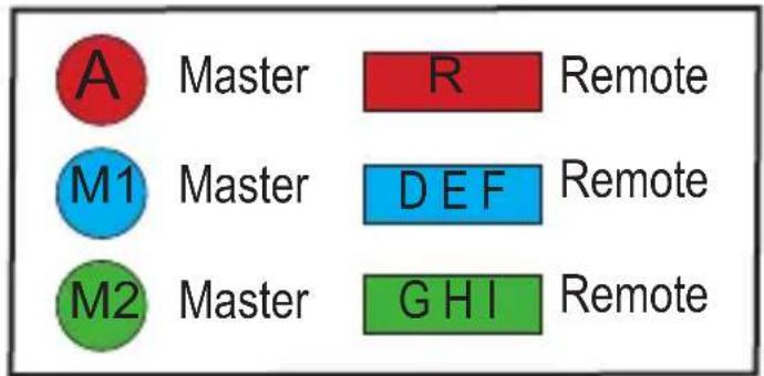

flowchart
graph TD
    A["Master A"] --> B["Device"]
    B --> C1["Device 1"]
    B --> C2["Device 2"]
    B --> C3["Device 3"]
    B --> C4["Device 4"]
    B --> C5["Device 5"]
    B --> C6["Device 6"]
    B --> C7["Device 7"]
    B --> C8["Device 8"]
    B --> C9["Device 9"]
    B --> C10["Device 10"]
    B --> C11["Device 11"]
    B --> C12["Device 12"]
    B --> C13["Device 13"]
    B --> C14["Device 14"]
    B --> C15["Device 15"]
    B --> C16["Device 16"]
    B --> C17["Device 17"]
    B --> C18["Device 18"]
    B --> C19["Device 19"]
    B --> C20["Device 20"]
    B --> C21["Device 21"]
    B --> C22["Device 22"]
    B --> C23["Device 23"]
    B --> C24["Device 24"]
    B --> C25["Device 25"]
    B --> C26["Device 26"]
    B --> C27["Device 27"]
    B --> C28["Device 28"]
    B --> C29["Device 29"]
    B --> C30["Device 30"]
    B --> C31["Device 31"]
    B --> C32["Device 32"]
    B --> C33["Device 33"]
    B --> C34["Device 34"]
    B --> C35["Device 35"]
    B --> C36["Device 36"]
    B --> C37["Device 37"]
    B --> C38["Device 38"]
    B --> C39["Device 39"]
    B --> C40["Device 40"]
    B --> C41["Device 41"]
    B --> C42["Device 42"]
    B --> C43["Device 43"]
    B --> C44["Device 44"]
    B --> C45["Device 45"]
    B --> C46["Device 46"]
    B --> C47["Device 47"]
    B --> C48["Device 48"]
    B --> C49["Device 49"]
    B --> C50["Device 50"]
    B --> C51["Device 51"]
    B --> C52["Device 52"]
    B --> C53["Device 53"]
    B --> C54["Device 54"]
    B --> C55["Device 55"]
    B --> C56["Device 56"]
    B --> C57["Device 57"]
    B --> C58["Device 58"]
    B --> C59["Device 59"]
    B --> C60["Device 60"]
    B --> C61["Device 61"]
    B --> C62["Device 62"]
    B --> C63["Device 63"]
    B --> C64["Device 64"]
    B --> C65["Device 65"]
    B --> C66["Device 66"]
    B --> C67["Device 67"]
    B --> C68["Device 68"]
    B --> C69["Device 69"]
    B --> C70["Device 70"]
    B --> C71["Device 71"]
    B --> C72["Device 72"]
    B --> C73["Device 73"]
    B --> C74["Device 74"]
    B --> C75["Device 75"]
    B --> C76["Device 76"]
    B --> C77["Device 77"]
    B --> C78["Device 78"]
    B --> C79["Device 79"]
    B --> C80["Device 80"]
    B --> C81["Device 81"]
    B --> C82["Device 82"]
    B --> C83["Device 83"]
    B --> C84["Device 84"]
    B --> C85["Device 85"]
    B --> C86["Device 86"]
    B --> C87["Device 87"]
    B --> C88["Device 88"]
    B --> C89["Device 89"]
    B --> C90["Device 90"]

flowchart
graph TD
    A["A"] --> B["B"]
    A --> C["C"]
    A --> J["J"]
    M1["M1"] --> R["R"]
    M2["M2"] --> G["G"]
    M2 --> H["H"]
    M2 --> I["I"]
    M1 --> D["D"]
    M1 --> E["E"]
    M1 --> F["F"]
    H --> G
    I --> H
    D --> E
    E --> F

Master

Remote

Master

Remote

Master
Remote
8 Person Talking in One Group or Split into Two Groups (Each Group Five Person)

flowchart
graph TD
    A["Master A N"] --> B["1"]
    A --> C["2"]
    A --> D["3"]
    A --> E["4"]
    A --> F["5"]
    G["Master A N"] --> H["1"]
    G --> I["2"]
    G --> J["3"]
    G --> K["4"]
    G --> L["5"]
    M["Master A N"] --> N["1"]
    M --> O["2"]
    M --> P["3"]
    M --> Q["4"]
    M --> R["5"]
    S["Master A N"] --> T["1"]
    S --> U["2"]
    S --> V["3"]
    S --> W["4"]
    S --> X["5"]
    Y["Master A N"] --> Z["1"]
    Y --> AA["2"]
    Y --> AB["3"]
    Y --> AC["4"]
    Y --> AD["5"]
Expanding to 20 Person Talking or Split into 2/3/4 Different Groups

flowchart
graph TD
    A["Master A"] --> B["3.5mm Audio Cable"]
    B --> C["Master A Group"]
    style A fill:#f9f,stroke:#333
    style B fill:#ccf,stroke:#333
    style C fill:#cfc,stroke:#333
    note right of B: "Make sure connect with two different groups"
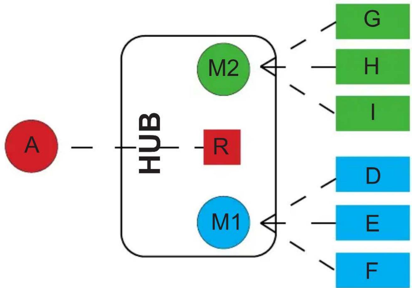
The Hub incorporates two Masters and one built-in Remote.
Each Master within the Hub can accommodate up to 3 Remotes.
With this configuration, a single hub enables connections for up to 10 NANO within a single system, while two hubs can facilitate connections for up to 20 NANO.
(Please refer to the pairing diagram above for further guidance.)
The hub has a micro USB port to power/charge the unit via 5V DC with a USB power supply or power bank.
When power is connected it can run directly without batteries and also charge when batteries are installed. The Hub can run alone on batteries and with one installed run time is about 8-10 hours and with two batteries installed, the run time increases to about 15-18 hours.

3.5mm TRRS audio jack It adheres to the United States CTIA standard.
If your equipment follows the OMTP standard, you will need to use a conversion cable.
USB Function
- Direct Power Supply to the HUB
- Charge batteries in the battery compartment.
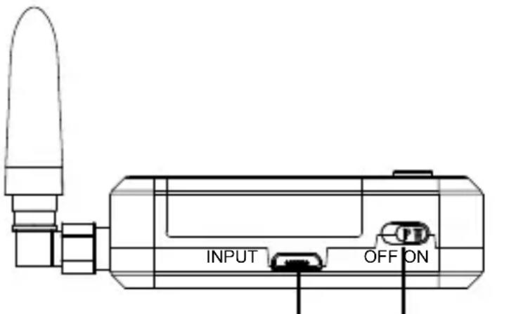
USB 5V Switch button

1 Working indicator for M1 group
2 Working indicator for HUB remote
3 Working indicator for M2 group
4 Master 1 button
5 Remote button Master 2 button
6
7 Charging indicator
8 Power indicator
9 Charging indicator Battery compartment
As long as an NB-6L battery is present in the battery compartment, it will constantly supply power to the hub.
If there is no battery, the hub can also be connected to an external power supply through the USB port.
With an external USB power supply, the HUB can also charge the batteries placed inside it.

Working Indicator for M1 and M2
The working indicator aids in distinguishing the Master to which the remote belongs.
When viewed vertically from the top, the M1 and M2 indicators display the number of remotes they are connected to, with each Master capable of connecting to up to 3 remotes.
Consequently, up to 6 indicators can illuminate simultaneously.
If a remote powers off or disconnects, the corresponding indicator will extinguish. For instance, if one of the remotes connected to M1 powers off, only two of M1's indicators will remain lit, while M2's indicators will remain unaffected.
The product comes pre-paired, allowing immediate use upon switching on the device without any additional steps. Pairing becomes necessary only if a remote loses connection with the master.
Pairing Steps
① Ensure that both the Master and all Remote devices are powered on. When the Master enters the pairing state, any remotes not powered on will be cleared from the set.
② Simultaneously press the "Volume Up" and "Volume Down" buttons on the Master until the green LED indicator begins flashing quickly and the sound of "pairing" is heard, indicating it has entered the pairing state. And then activate the pairing mode of remote Nano, it follows the same pairing activation steps by simultaneously pressing the volume up and down buttons. Start by pairing one remote, once it says "your headset is connected" then proceed to pair the remaining lost remotes one by one in sequence.
③ The master will automatically exit the pairing state and the LED will become solid once it is fully connected with all 4 remotes. If there are fewer than 4 remotes, you can manually exit the pairing state by pressing the master Nano "Mute On/off "button. If you want to pair a remote with a new master, be sure to turn off the previous master that was paired with that remote before initiating the new pairing process.
These are precise pairing procedures. It is strongly recommended to follow the guide carefully and accurately for successful operation of this unit.
Pairing
The product comes pre-paired, allowing immediate use upon switching on the device without any additional steps. Pairing becomes necessary only if a remote loses connection with the master.
It is important to check the disconnected remote ID number to identify which group master it belongs to:
- Master A group (Remote Hub R and Remote B/C/J)
- Hub M1 group (Remote D/E/F)
- Hub M2 group (Remote G/H/I)
Make sure to pair the disconnected group only. Ensure that both the master and all remote devices in the disconnected group are powered on. When the Master enters the pairing state, any remotes not powered on in the same group will be cleared.
\*\*Pairing Steps for Different Group Remotes:\*\*
① Pairing Master A with Remote Hub R and Remote NANO B/C/J: (In below two circumstances, make sure Master A, Remote Hub R, and Remote NANO B/C/J are powered on.)
If it is Remote B/C/J disconnected from Master A:
- Activate the pairing mode of Master A by pressing the "Volume Up" and "Volume down" buttons simultaneously, once the LED indicator starts flashing quickly and the sound of "pairing" is heard, indicating it has entered the pairing state. And then activate the pairing mode of lost remote Nano. Start by pairing one remote, once it says "your headset is connected" then proceed to pair the remaining lost remotes one by one in sequence.
If it is Remote Hub R disconnected from Master A:
- Press the Volume Up and Down keys simultaneously on Master A until the LED indicator starts flashing quickly to enter the pairing state.
-Press and hold the middle button on remote Hub R until the Blue LED indicator starts flashing quickly to enter the pairing state.
-Once they are successfully connected with each other, the working indicator for hub remote R will become solid. The Master A will automatically exit the pairing state and the LED will become solid once it is fully connected with 4 Remotes(Remote Hub R and Remote NANO B/C/J). If there are fewer than 4 remotes, you can manually exit the pairing state by pressing the master A mute button.
\*\*Pairing Steps for Different Group Remotes:\*\*
② Pairing the Hub M1 group (Remote D/E/F):
- Ensure that both the Hub M1 and all Remote D/E/F are powered on.
- Press and hold the left button on Hub M1 until the blue LED indicator starts flashing quickly to enter the pairing state.
Simultaneously press the "Volume Up" and "Volume Down" buttons on the disconnected remote Nano until the LED starts flashing quickly, you will hear the sound of pairing from the remote. Begin by pairing one remote first, then proceed to pair the remaining lost remotes one by one in sequence.
- Hub M1 will automatically exit the pairing state, and the LED will become solid once it is fully connected with 3 remotes (Remote D/E/F). If there are fewer than 3 remotes, you can manually exit the pairing state by long-pressing the HUB M1 button.
③ Pairing the Hub M2 group (Remote G/H/I):
- Ensure that both the Hub M2 and all Remote I/H/G are powered on.
- Long-press the Hub M2 button to activate the pairing process. The procedure is similar to the step above.
① The Master module and remote module in the hub cannot be paired at the same time, as it may result in malfunction.
② It is crucial to identify the group that the disconnected remote belongs to before pairing.
③ Pairing is only needed for the disconnected group, and ensure that all remotes in the same group are powered on before pairing.
FCC Regulatory Compliance
This device complies with Part 15 of the FCC Rules.
Operation is subject to the following two conditions:
(1) this device may not cause harmful interference, and (2) this device must accept any interference received including interference that may cause undesired operation.
Warning: changes or modifications not expressly approved by the party responsible for compliance could void the user's authority to operate the equipment.
Note: This equipment has been tested and found to comply with the limits for a Class B digital device, pursuant to Part 15 of the FCC Rules. These limits are designed to provide reasonable protection against harmful interference in a residential installation. This equipment generates, uses and can radiate radio frequency energy and, if not installed and used in accordance with the instructions, may cause harmful interference to radio communications. However, there is no guarantee that interference will not occur in a particular installation.
If this equipment does cause harmful interference to radio or television reception, which can be determined by turning the equipment off and on, the user is encouraged to try to correct the interference by one or more of the following measures:
--Reorient or relocate the receiving antenna.
--Increase the separation between the equipment and receiver.
--Connect the equipment into an outlet on a circuit different from that to which the receiver is connected.
--Consult the dealer or an experienced radio/TV technician for help.
FCC RF Radiation Compliance
The device has been tested and comply with FCC SAR limits.
This transmitter must not be co-located or operating in conjunction with any other antenna or transmitter.
While we trust you will never have the need, if you do, our service is both friendly and hassle-free.
Email:
Americas: americas@came-tv. com
Outside Americas: europe@came-tv.com
Follow Us:
https://www.facebook.com/CameTvGear/
https://www.instagram.com/cametv/
https://www.youtube.com/c/CameTVgear/videos
https://www.twitter.com/CameTV
- O N A Z
- Suggestions for optimal use
- CAME-NANO
- Product Structure
- Person Team Max Distance 2200ft
- Person Team
- Max Distance 2200ft
- USB Function
- Working Indicator for M1 and M2
- Pairing Steps
- Pairing
- \*\*Pairing Steps for Different Group Remotes:\*\*
- If it is Remote B/C/J disconnected from Master A:
- If it is Remote Hub R disconnected from Master A:
- FCC Regulatory Compliance
- FCC RF Radiation Compliance
- Email:
- Follow Us:
Brand : CAME-TV
Model : NANO
Category : Intercom