VoiceLift Pro Microphone - Microphone Extron - Free user manual and instructions
Find the device manual for free VoiceLift Pro Microphone Extron in PDF.


| Product Type | Voice Amplification Microphone System |
| Brand | Extron |
| Model | VoiceLift Pro Microphone (VLM 3001, VLM 3002, VLM 3002H) |
| Microphone Types | VLP 302 Pendant, VLH 302 Handheld |
| Receiver Model | VLR 302 |
| Charging Station | VLC 302 (dual microphone charger) |
| Number of Supported Microphones | Up to 2 per receiver |
| Audio Output | Balanced mono line level (-10 dBV) via RJ-45 |
| Power Supply | Receiver powered by PVCA 452 or PVS 407D via STP cable; Charger via external 5VDC 2.6A adapter |
| Battery Type | 1x AA NiMH (rechargeable) or alkaline |
| Charging Time | Up to 5 hours |
| DSP Features | Integrated digital signal processing with feedback suppression |
| Mounting Options (Receiver) | Rack mount, wall mount, ceiling mount (with PlenumVault PVM 220, ZipClip 400) |
| Relay Outputs | 2 normally open relays (for instant alerts) |
| Control | SIS commands via USB, or via PVCA/PVS |
| Firmware Update | Via USB using Extron Firmware Loader |
| Compliance | FCC Part 15 Class B, Industry Canada RSS |
| Warranty | 3 years |
| Included Accessories (VLM Kit) | Microphones, receiver, charging station, power supply, STP cable, lanyard, labels, captive screw connectors |
| Maintenance | Clean with dry cloth; use only specified batteries |
| Safety | Warnings: electric shock, battery explosion, FCC interference |
Frequently Asked Questions - VoiceLift Pro Microphone Extron
User questions about VoiceLift Pro Microphone Extron
0 question about this device. Answer the ones you know or ask your own.
Ask a new question about this device
Download the instructions for your Microphone in PDF format for free! Find your manual VoiceLift Pro Microphone - Extron and take your electronic device back in hand. On this page are published all the documents necessary for the use of your device. VoiceLift Pro Microphone by Extron.
USER MANUAL VoiceLift Pro Microphone Extron
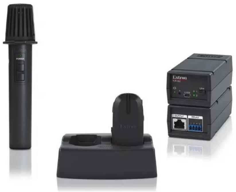
VoiceLift Pro Microphones
VoiceLift Pro Microphone Kits (VLM) and VoiceLift Pro Microphone Systems (VLS)
User Guide
VoiceLift
Safety Instructions • English

WARNING: This symbol, when used on the product, is intended to alert the user of the presence of uninsulated dangerous voltage within the product's enclosure that may present a risk of electric shock.
ATTENTION: This symbol, when used on the product, is intended to alert the user of important operating and maintenance (servicing) instructions in the literature provided with the equipment.
For information on safety guidelines, regulatory compliances, EMI/EMF compatibility, accessibility, and related topics, see the Extron Safety and Regulatory Compliance Guide, part number 68-290-01, on the Extron website, www.extron.com.
All trademarks mentioned in this guide are the properties of their respective owners.
The following registered trademarks (®), registered service marks (SM), and trademarks (TM) are the property of RGB Systems, Inc. or Extron (see the current list of trademarks on the Terms of Use page at www.extron.com):
| Registered Trademarks (®) |
| Extron, Cable Cubby, ControlScript, CrossPoint, DTP, eBUS, EDID Manager, EDID Minder, eLink, Flat Field, FlexOS, Glitch Free, Global Configurator, Global Scripter, GlobalViewer, Hideaway, HyperLane, IP Intercom, IP Link, Key Minder, LinkLicense, LockIt, MediaLink, MediaPort, NAV, NetPA, PlenumVault, PoleVault, PowerCage, PURE3, Quantum, ShareLink, Show Me, SoundField, SpeedMount, SpeedSwitch, StudioStation, System INTEGRATOR, TeamWork, TouchLink, V-Lock, VideoLounge, VN-Matrix, VoiceLift, WallVault, WindoWall, XPA, XTP, XTP Systems, and ZipClip |
| Registered Service Mark ^(SM) : S3 Service Support Solutions |
| Trademarks ^(TM) |
| AAP, AFL (Accu-RATE Frame Lock), ADSP (Advanced Digital Sync Processing), AVEdge, CableCover, CDRS (Class D Ripple Suppression), Codec Connect, DDSP (Digital Display Sync Processing), DMI (Dynamic Motion Interpolation), Driver Configurator, DSP Configurator, DSVP (Digital Sync Validation Processing), EQIP, Everlast, FastBite, Flex55, FOX, FOXBOX, IP Intercom HelpDesk, MAAP, MicroDigital, Opti-Torque, PendantConnect, ProDSP, QS-FPC (QuickSwitch Front Panel Controller), Room Agent, Scope-Trigger, SIS, Simple Instruction Set, Skew-Free, SpeedNav, Triple-Action Switching, True4K, True8K, Vector ^TM 4K, WebShare, XTRA, and ZipCaddy |
FCC Compliance Statement
NOTE: For more information on safety guidelines, regulatory compliances,
EMI/EMF compatibility, accessibility, and related topics, see the Extron Safety and Regulatory Compliance Guide on the Extron website.
This device complies with Part 15 of the FCC Rules for portable devices only.
Operation is subject to the following two conditions: (1) This device may not cause harmful interference, and (2) This device must accept any interference received, including interference that may cause undesired operation of the device.
Changes or modifications to the equipment not expressly approved by Extron could void the user's authority to operate the equipment.
NOTE: This equipment has been tested and found to comply with the limits for a Class B digital device, pursuant to Part 15 of the FCC Rules. These limits are designed to provide reasonable protection against harmful interference in a residential installation.
This equipment generates, uses and can radiate radio frequency energy and, if not installed and used in accordance with the instructions, may cause harmful interference to radio communications. However, there is no guarantee that interference will not occur in a particular installation.
If this equipment does cause harmful interference to radio or television reception, which can be determined by turning the equipment off and on, the user is encouraged to try to correct the interference by one or more of the following measures:
• Reorient or relocate the receiving antenna
- Increase the separation between the equipment and receiver
- Connect the equipment into an outlet on a circuit different from that to which the receiver is connected.
- Consult the dealer or an experienced radio/TV technician for help.
The VoiceLift Pro System has been tested/evaluated and found to comply with the FCC radiated exposure limits and meets the FCC radio frequency (RF) Exposure Guidelines. The Receiver unit must be installed and operated keeping it at least 20 cm away from the person's body. The system must not be co-located or operating in conjunction with any other antenna or transmitter.
Canada Compliance Statement
This device complies with Industry Canada license exempt RSS standard(s). Operation is subject to the following two conditions: (1) this device may not cause interference, and (2) this device must accept any interference, including interference that may cause undesired operation of the device.
Conventions Used in this Guide
Notifications
The following notifications are used in this guide:

WARNING: Potential risk of severe injury or death.
CAUTION: Risk of minor personal injury.
NOTE: A note draws attention to important information.
TIP: A tip provides a suggestion to make working with the application easier.
Software Commands
Commands are written in the fonts shown here:
^AR Merge Scene,,0p1 scene 1,1 ^B 51 ^W^C.0
[01]R000400300004000080000600[02]35[17][03]
Esc X1 *X17 *X20 *X23 *X21 CE←
NOTE: For commands and examples of computer or device responses used in this guide, the character "O" is the number zero and "O" is the capital letter "o."
Computer responses and directory paths that do not have variables are written in the font shown here:
Reply from 208.132.180.48: bytes=32 times=2ms TTL=32
C:\Program Files\Extron
Variables are written in italics as shown here:
ping xxx.xxx.xxx.xxx —t
SOH R Data STX Command ETB ETX
Selectable items, such as menu names, menu options, buttons, tabs, and field names are written in the font shown here:
From the File menu, select New.
Click the OK button.
Specifications Availability
Product specifications are available on the Extron website, www.extron.com.
Extron Glossary of Terms
A glossary of terms is available at https://www.extron.com/technology/glossary.aspx
Contents
Introduction....1
About this Guide....1
About the VoiceLift Pro Microphone Kits (VLM Kits)....2
About the VoiceLift System (VLS) 3
VoiceLift Pro Microphone Features 4
Application Diagram 5
VLM Kit Installation and Operation....6
VoiceLift Pro Microphone Kit Overview ...... 6
VLP 302 Microphone Features....7
VLH 302 Microphone Features....9
Installing the VLC 302 Charger and Charging the Microphones .... 10
Installing the VLR 302 Receiver....11
Feedback Suppression....11
Connections....11
Setting up the Microphones....13
VLP 302 Pendant Microphone....13
VLH 302 Handheld Microphone 14
Saving the Microphone Volume....14
Pairing the Microphones with the VLR 302 ..... 15
Verify which Microphones are Paired ..... 15
Pair New Microphones 15
Setting up VLP 302 Instant Alerts....16
Tips for Using the Microphones....16
VoiceLift System Installation....17
Recommended Installation Tools....17
Step 1 — Mount the VLR 302 Receiver ..... 18
Rack Mounting....18
ZipClip Mounting Kit (optional)....19
Step 2 — Mount the FF 120 Speakers......19
Step 3 — Install the PVCA 452 Controller
Amplifier 22
PVCA 452 Installation....22
Step 4 — Connect the Receiver and Speakers to the PVCA 452....23
Step 5 — Set up the Microphones and Test the System....24
SIS Configuration and Control....25
Overview.... 25
Host to Receiver Communications 25
Error Response 25
Timeout....25
Commands and Responses 26
Using the Command and Response Table....26
Symbol Definitions....26
Command and Response Table for SIS Commands 27
Reference Information 28
Updating Firmware with Firmware Loader ..... 28
Downloading Extron Firmware Loader ..... 28
Installing Firmware Loader 28
Downloading Firmware 29
Installing Firmware with Firmware Loader...29
Resetting the VLR 302 30
Reset Mode 1 30
Reset Mode 2 30
Reset Mode 3 30
Introduction
This section covers the following topics:
- About this Guide
- About the VoiceLift Pro Microphone Kits (VLM Kits)
• About the VoiceLift System (VLS)
• VoiceLift Pro Microphone Features
• Application Diagram
About this Guide
This guide describes the components, installation, and operation of the Extron VoiceLift Pro Microphone Kit and the VoiceLift Pro System.
- VoiceLift Pro Microphone Kits (VLM kits) include the pendant or handheld microphones, the receiver, and the charging station (see About the VoiceLift Pro Microphone Kits on the next page for details).
NOTE: VoiceLift Pro Microphone Kits can be part of a VoiceLift System or can be installed and used within a new or existing PoleVault, WallVault, PlenumVault, or PlenumVault Direct View System.
- VoiceLift Systems (VLS) include a microphone kit, a PVCA 452 Controller Amplifier or PVS 407D switcher, and FF 120 Flat Field speakers (see About the VoiceLift System (VLS) on page 3 for details).
CAUTION: Risk of explosion. Do not replace the battery with an incorrect type. Dispose of used batteries according to the instructions.
The following terms are used in this guide:
- "Microphone" refers to the VLP 302 or VLH 302.
- “Receiver” refers to the VLR 302 receiver. The receiver can be mounted into Extron enclosures or can be rack mounted. One receiver can host up to two microphones.
- “Charging station” refers to the VLC 302 charger for dual microphones (VLP or VLH).
- "PoleVault switcher" refers to the PVS 407D PoleVault switcher. For details about the PVS 407D switcher, see the PVS 407D PoleVault Digital Switcher User Guide.
About the VoiceLift Pro Microphone Kits (VLM Kits)
A VoiceLift Pro Microphone Kit is a classroom voice amplification system that enables a teacher or presenter to be clearly heard at a comfortable level throughout the entire room.
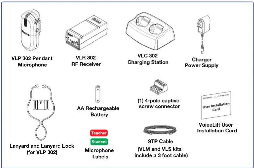
There are three types of VoiceLift VLM kits available (versions for the European market include the VLR 302 EU receiver):
• VLM 3001 / VLM 3001 EU includes:
One VLP 302 pendant microphone, a VLR 302 receiver, and a VLC 302 charging station.
• VLM 3002 / VLM 3002 EU includes:
Two VLP 302 pendant microphones, a VLR 302 receiver, and a VLC 302 charging station.
• VLM 3002H / VLM 3002H EU includes:
One VLP 302 pendant microphone, one VLH 302 handheld microphone, a VLR 302 receiver, and a VLC 302 charging station.
NOTES:
- A VLM kit can be integrated into an existing PoleVault, WallVault, PlenumVault, or PlenumVault Direct View System. For details about integrating a VLM kit into an existing system, see the PoleVault Digital Systems (featuring the PVS 407D) Installation Guide or the PlenumVault Direct View Systems Installation Guide (included with the installed system and also available at www.extron.com).
- If any items in the VLM kit are damaged or missing, contact the Extron S3 Sales & Technical Support Hotline.
About the VoiceLift System (VLS)
The VoiceLift System consists of a VLM kit, a PVS 407D PoleVault Switcher or PVCA 452 Controller Amplifier, and two FF 120 speakers. There are three types of VoiceLift systems:
• VLS 3001, VLS 3001W, and VLS 3001P contain:
The VLM 3001 kit, a PVCA 452 Controller Amplifier, and two FF 120 speakers.
• VLS 3002, VLS 3002W, and VLS 3002P contain:
The VLM 3002 kit, a PVCA 452 Controller Amplifier, and two FF 120 speakers.
• VLS 3002H, VLS 3002HW, and VLS 3002HP contain:
The VLM 3002H kit, a PVCA 452 Controller Amplifier, and two FF 120 speakers.
VLM Kits
• VLM 3001, VLM 3001W, VLM 3001P: VLP 302 (1) + VLR 302 (1) + VLC 302 (1)
• VLM 3002, VLM 3002W, VLM 3002P: VLP 302 (2) + VLR 302 (1) + VLC 302 (1)
• VLM 3002H, VLM 3002HW, VLM 3002HP: VLP 302 (1) + VLH 302 (1) + VLR 302 (1) + VLC 302 (1)

VLP 302 Pendant Microphone

VLC 302
Charging Station

Charger
Power Supply
VLR 302 / VLR 302 EU
RF Receiver

Lanyard and Lanyard Lock (for VLP 302)

AA Rechargeable Battery


Microphone Labels

STP Cable
(VLM kits include a
3 foot cable)

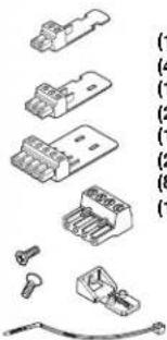
(1) 4-pole Captive Screw Connector

VoiceLift User Installation Card
PVCA 452 Controller Amplifier

natural_image
Illustration of various electronic components including connectors, batteries, and a plug (no text or symbols present)(1) 2-pole connector
(4) 3-pole connectors
(1) 4-pole connector
(2) 5-pole connectors
(1) Audio connector, 4-pole
(2) Securing screws
(8) Tie wraps
(1) HDMI LockIt brackets

100 feet (30.4 m) Speaker Cable

(1) Power Supply (1) Power Cord
FF 120 Speakers

natural_image
Isometric line drawing of a rectangular electronic component with a central mounting hole (no text or symbols)
natural_image
Illustration of three parallel metal rods with a separate small mechanical component (no text or symbols)(2) Cable clamps and Anchor rings (2) T-rails
A VoiceLift system can operate in either single or dual microphone configurations. Dual microphones (typically assigned as Instructor and Student microphones) may be used individually or simultaneously (see VoiceLift Pro Microphone Kit Overview on page 6 for more information).
NOTE: If any VoiceLift System items are damaged or missing, contact the Extron Technical Support Hotline.
VoiceLift Pro Microphone Features
- Lightweight microphones — The microphones are made of lightweight and impact-resistant polycarbonate material. The VLP 302 pendant microphone can be worn comfortably around the neck or clipped to clothing. The VLH 302 can be used for multiple presenters and as a student pass-around microphone.
- Built-in DSP — The receiver has integrated digital signal processing (DSP) with feedback suppression that maximizes sound quality and intelligibility.
- Two microphones per classroom — An installed VoiceLift System supports up to two microphones in each classroom and can be used by instructors and students.
- Power switch — The VLP 302 pendant microphone has an easily accessible switch on the side to mute the sound and power the microphone on and off. The VLH has a sliding switch that toggles the microphone on and off.
- Volume buttons — Volume buttons on the VLP 302 are conveniently located, enabling the presenter to easily raise and lower the volume during use. Volume buttons on the VLH 302 are hidden within the battery compartment.
- Instant alert e-mail messaging — The VoiceLift receiver can be configured to allow the teacher to send e-mail alerts, if needed, by pressing the VLP microphone Volume buttons.
• Auxiliary microphone input (VLP 302) allows use of an optional lavalier or headset microphone. - Auxiliary audio input (VLH 302) for an external audio source, such as an MP3 player.
- Battery power — The VLP 302 and VLH 302 microphones are powered by a single NiMh or alkaline AA battery. NiMh batteries can be recharged in the VLC 302 charging station.
• VLC 302 charging station — Holds and recharges up to two microphones. - Receiver mounting options — The VLR 302 receiver is compact and can be mounted within Extron enclosures or can be rack mounted.
Application Diagram
The application diagram below shows a typical classroom installation incorporating the VoiceLift System.

flowchart
graph TD
    A["Extron FF 120 Flat Field Speakers"] --> B["Extron VLM 3002H VoiceLift Pro Pendant, Handheld, and Charging Station"]
    B --> C["Laptop"]
    C --> D["HDMI"]
    D --> E["Laptop"]
    E --> F["Extron WPD 110 A Pass-Through Wallplate"]
    F --> G["eBUS Button Panel"]
    G --> H["Extron EF 120 Flat Field Speakers"]
    H --> I["Extron PVCA 452 Controller Amplifier"]
    I --> J["Extron PVM 220 PlenumVault Mounting Kit"]
    J --> K["Extron VLR 302 VoiceLift Pro Receiver"]
    K --> L["TCP/IP Network"]
    L --> M["RF 232"]
    M --> N["Ethernet"]
    N --> O["Computer"]
Figure 1. PVDV 101 PlenumVault Direct View System
VLM Kit Installation and Operation
This section covers the following topics:
• VoiceLift Pro Microphone Kit Overview
• Installing the VLC 302 Charger and Charging the Microphones
• Installing the VLR 302 Receiver
- Setting up the Microphones
• Pairing the Microphones with the VLR 302
- Setting up VLP 302 Instant Alerts
• Tips for Using the Microphones
VoiceLift Pro Microphone Kit Overview
The figure below shows the path of the audio signal through the VoiceLift System.

Figure 2. VoiceLift System Audio Signal Path
A — VLP or VLH microphone (see next page)
B — VLR 302 receiver
© — PoleVault switcher
D — PVCA 452 Controller Amplifier
A VLP or VLH microphone — The VLP 302 or VLH 302 microphone transmits the voice audio signal to the VLR 302 receiver.
B VLR 302 receiver — The VLR 302 receives the signal from the microphone, and outputs a balanced, mono, line level signal (-10 dBV) to the PoleVault switcher.
PoleVault switcher — The PVS 407D PoleVault switcher functions as an amplifier for the VoiceLift System. It amplifies the audio signal from the VLR 302 receiver and sends it to the speakers. The switcher powers speakers placed throughout the room to improve the signal-to-noise ratio of the voice to at least +15 dB.
PVCA 452 Controller Amplifier — The PVCA 452 functions as an amplifier for the VoiceLift System. It amplifies the audio signal from the VLR 302 receiver and sends it to the speakers. The controller amplifier powers speakers placed throughout the room to improve the signal-to-noise ratio of the voice to at least +15 dB.
VLP 302 Microphone Features
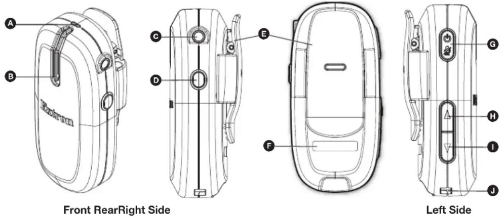
Figure 3. VLP 302 Microphone Features
A — Status LED (tri-color) (see next page)
B — Microphone acoustic ports
C — Auxiliary microphone input (3.5 mm mono female input jack)
D — Function button
E — Spring clip
F — Microphone identification label recess
G — Power/mute button
H — Volume ▲button (increase)
① — Volume ▼button (decrease)
J — Charging contacts
A Status LED — This LED indicates the microphone power, volume, and charging status as follows: LED indicators when the microphone is powered on and in use:
| LED Color Indication | |
| LED off Microphone is OFF or battery not installed | |
| Green – steady Microphone is ON | |
| Green – slow blinking Microphone is muted | |
| Green – single blink Volume adjusted (increased or decreased) | |
| Red – slow blinking Low battery (30 minutes or less of talk time left). Recharge battery. | |
| Red – steady Battery life depleted. Recharge battery. | |
| Red – steady (5 seconds) | Instant Alert activated. Volume Up and Down buttons were pressed and held simultaneously for 3 seconds (relay 1 triggered).LED and relay revert states after 5 seconds. |
| Amber (blinks for 5 seconds) | Function button activated.Function button was pressed and held for 2 seconds (relay 2 is triggered and latches to opposite state). |
| Red and green – alternate blinking Microphone in discovery mode and attempting to pair with receiver | |
LED indicators when the microphone is charging:
| LED Color Indication | |
| Red – steady Battery charging | |
| Green – steady | Battery fully charged |
| Red and green – alternate blinking | Incompatible, faulty or failed battery detected. Replace battery. |
B Microphone acoustic audio input ports — The microphone receives voice audio through these two acoustical ports. Do not block these ports while the microphone is in use.
Auxiliary microphone input (Audio In) — Connect an optional lavalier microphone to this 3.5 mm mono TS (tip/sleeve) aux audio input (see the diagram at right for connector wiring).
NOTE: When an external lavalier microphone is connected, the built in microphone elements in the VLP 302 are disabled.

D Function button — When this button is pressed and held for two seconds, the microphone signals the receiver to toggle relay 2 to its opposite state.
NOTE: The status LED flashes amber for 5 seconds, indicating that the relay has been toggled.
Also, when this button is pressed simultaneously with the Power button, it initiates Link (pairing) mode.
E Spring clip — Use this clip to attach the VLP 302 to clothing or to a lanyard (included) (see step 4 on page 13 for instructions).
The lanyard lock is used to retain proper position of the microphone when clipped to the lanyard. The breakaway clasps help to release the lanyard from around the neck if it is pulled tightly. Place this clasp at the back of your neck when wearing the pendant microphone.
F Microphone identification label recess — Place the appropriate provided sticker in this space to identify the microphone user (see step 3 on page 13).
G Power and mute button (Off/Mute/On) — Press and hold the Power button (for three seconds) to power the microphone on or off.
With the device on, press and release this button momentarily to mute or unmute the microphone.
H I Volume buttons — Press these buttons to raise or lower the microphone volume.
Pressing and holding both of these buttons simultaneously for 3 seconds sends a signal to the receiver to close its relay 1 port. This is typically used to trigger an alert (see Setting up VLP 302 Instant Alerts on page 16).
Charging contacts — These make contact with the contacts in the charging station when placed into the VLC 302. A full charge can take up to 5 hours.
VLH 302 Microphone Features
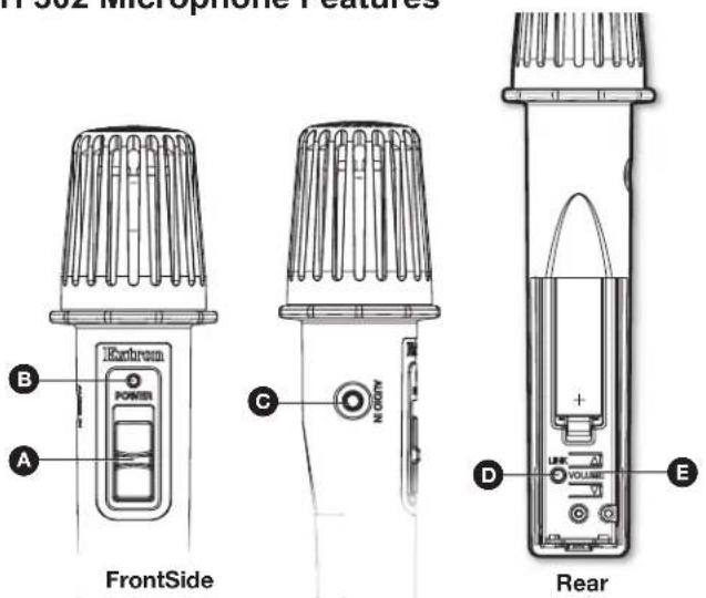
Figure 4. VLH 302 Microphone Features
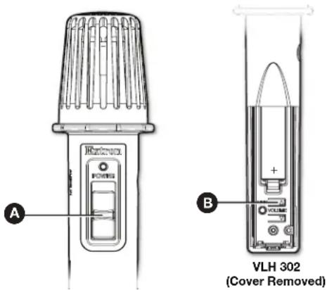
A Power switch — Slide up to power on and down to power off.
Power status LED — Dual color LED (green and red) indicates power or Link status. LED indicators when the microphone is powered on and in use:
| LED Color Indication | |
| LED off Microphone is off or battery | is not installed. |
| Green – steady Microphone is on. | |
| Green – single blink Volume has been adjusted (increased or decreased). | |
| Red – slow blinking Low battery (30 minutes or less of talk time left). Recharge battery. | |
| Red – steady Battery life is depleted. Recharge battery. | |
| Red and green – alternating blinks | Microphone is in discovery mode and attempting to pair with receiver. |
LED indicators when the microphone is charging:
| LED Color Indication | |
| Red – steady Battery is charging. | |
| Green – steady Battery is fully charged. | |
| Red and green – alternating blink | Incompatible, faulty, or failed battery detected. Check and replace battery. |
Auxiliary stereo audio input — Connect audio devices (such as mobile devices, MP3 players, etc.) to this aux audio input to wirelessly transmit audio to the room speakers. Use a 3.5 mm stereo TRS (tip/ring/sleeve) cable to connect the audio source to the aux audio input (see the diagram at right for connector wiring).
NOTE: 3.5 mm stereo input accepts line level audio signals, but does not support external lavalier/lapel microphones. When an active auxiliary input device is connected, the built in microphone is disabled. The audio from the auxiliary audio source is summed to mono and transmitted to the receiver.
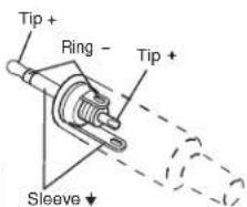
TRS Connector
D Link button — Use this button to enable pairing mode.
E Volume buttons — Increase (▲) or decrease (▼) the microphone volume.
Installing the VLC 302 Charger and Charging the Microphones
The VLC 302 charges the microphone battery. It is powered by an external wall power supply (provided). The microphone battery requires up to 5 hours to charge fully. It is safe to charge for extended periods, but Extron recommends storing the microphone out of the charger with the battery removed.
NOTES:
- The charging station is to be used with NiMH rechargeable batteries only.
• Fully charge the supplied batteries before first use.
Follow these steps to connect the charger and charge the microphones.
- Connect the 5 VDC, 2.6 A wall charger (with USB Mini-B adapter) to a 110-130 VAC (U.S.) or a 100-240 VAC (international), 50-60 Hz power source (see ① at right).
- Connect the USB mini plug end of the adapter to the USB mini jack located on the back of the VLC 302 (see ② at right).

- To install the battery, remove the microphone battery cover as follows:
• VLP 302: Unscrew the two rear panel screws located on either side of the rear clip.
- VLH 302: Slide the battery cover downward until it stops, then lift the cover up and off the microphone.
Insert the battery, aligning the + and - poles as indicated inside the compartment.
CAUTION: Use only NiMH rechargeable batteries provided by Extron when charging the microphone. Use of any rechargeable battery other than the type provided by Extron may cause explosion, chemical leakage, and injury.
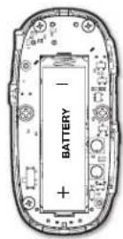
VLP 302
(Cover Removed)

VLH 302
(Cover Removed)
ATTENTION: Be sure to replace the battery with the correct type and to dispose of used batteries appropriately.
- Insert the microphone into one of the charger slots (④).
The microphone LED turns red when the microphone is charging.
| LED Color Indication | |
| Red – steady Battery charging | |
| Green – steady Battery fully charged | |
| Red and green – alternate blinking | Incompatible or failed battery detected. Check and replace battery. |

NOTES:
- The microphone battery requires up to 5 hours to charge fully. It is safe to charge for extended periods, but if microphones will not be used for extended durations, Extron recommends storing the microphone out of the charger with the battery removed.
- Make sure that the microphones are fully seated in the charging station to ensure proper charging.
ATTENTION:
Installing the VLR 302 Receiver
The VLR 302 receiver outputs audio signals from the microphones as one balanced mono line level signal to the PVCA 452 controller amplifier, PVS switcher or connected audio amplifier. In dual microphone systems, the signals from the two microphones are mixed at the receiver and then output to the connected audio amplifier.
Feedback Suppression
This feature activates signal processing to automatically suppress audio feedback. Feedback suppression can be enabled using SIS commands or through the PCS software application. When using PCS, the feature may be enabled from within the PVCA 452 or PVS 407D configuration screen or via direct USB connection to the VLR 302.
The feedback suppressor automatically inserts notch filters at the frequencies where feedback is detected. Filters are held for 60 minutes (default). However, filter hold time can be adjusted through SIS commands (see SIS Configuration and Control on page 25 for command and adjustment range).
Connections
Connect the VLR 302 to the PVCA 452 controller amplifier or PVS 407D PoleVault switcher as shown on the next page. For mounting options and instructions, see Step 1 — Mount the VLR 302 Receiver on page 18.

A B

©
D
Figure 5. VLR 302 Front and Rear Panel
A Reset button — Use this button to reset the receiver (see Resetting the VLR 302 on page 30).
B Mini USB configuration port — Connect a laptop or PC to this port using a suitable USB cable for device configuration and firmware updates only.
C RJ-45 output connector — Connect the PVCA 452 or PVS 407D to this RJ-45 connector, using the included shielded RJ-45 cable as shown below.
NOTE: The receiver is powered by the PVCA 452 or PVS switcher. This connection also allows for communication between the switcher and the receiver, to send configuration commands and receive relay status information.

PVCA 452
VLR 302 Receiver
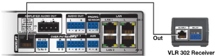
PVS 407D PoleVault Switcher
Figure 6. The VLR 302 Rear Panel
D Relays 1 and 2 (normally open/unlatched) — Wire this 4-pole captive screw connector for relays 1 and 2 (see Setting up VLP 302 Instant Alerts on page 16).
- Relay 1 is triggered to close (latched) for 5 seconds when both volume buttons on the VLP 302 microphone are pressed simultaneously for 3 seconds. VLP 302 status LED will illuminate RED when Relay 1 is triggered. The relay reverts to normally open once the 5 seconds has expired and the VLP 302 status LED changes back to green. Microphones must be configured as "teacher" microphones to trigger relays.
- Relay 2 is triggered to close when the Function button on the VLP 302 microphone (configured as "teacher") is pressed for 2 seconds. The relay toggles between closed (latched) and open states each time the Function button is pressed and held for 2 seconds. The VLP 302 status LED flashes amber for 5 seconds each time the Function button triggers Relay 2.
Setting up the Microphones
VLP 302 Pendant Microphone
- Verify that the battery is installed and fully charged.
-
Set the microphone(s) for either "teacher" or "student" mode using the DIP switch, accessible from beneath the battery cover (see ② at right):
-
In teacher mode (default), all microphone features are fully functional. Set the DIP switch to the OFF (down) position to enable teacher mode.
-
In student mode, all buttons are disabled except for the power button. Set the DIP switch to the ON (up) position to enable student mode.
-
Apply the appropriate label (provided) to identify the microphone (see ③ at right).

- To wear as a pendant microphone:
a. Open the microphone clip (see a at right).
b. Slide up the lanyard lock under the clip, then release the clip (b).
c. Place the lanyard around your neck. Adjust both lanyard straps so the microphone rests approximately 6 inches (15.2 cm) below your chin.
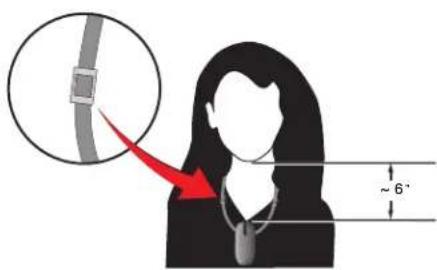
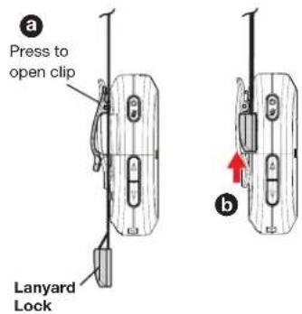
- Turn the microphone(s) on by holding the power button for three seconds (see ⑤ at right). One of the Link LEDs on the VLR 302 receiver will illuminate solid green to indicate that connection has been established.
NOTE: Each VLM kit includes microphones and a VLR 302 receiver that have already been paired. If there is a need to pair a microphone, follow the steps on the next page.
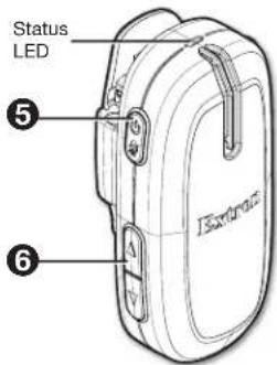
- Speak in a normal tone of voice, adjusting the volume level (⑥) as necessary (to save the volume level, see Saving the Microphone Volume Level on the next page).
- When finished, return the microphone to the charging station.
VLH 302 Handheld Microphone
- Verify that the battery is installed and fully charged.
- Turn the microphone on by sliding up the power switch (see Ⓐ at right).
NOTE: Each VLM kit includes microphones and a VLR 302 receiver that have already been paired. If there is a need to pair a microphone, follow the steps in the next section, below.
-
Speak in a normal tone of voice, adjusting the volume level as necessary. The volume buttons are located under the microphone cover (see B at right). To save the volume level, see Saving the Microphone Volume Level below.
-
When finished, return the microphone to the charging station.
Saving the Microphone Volume
Saving the microphone level allows the microphone to power on to the stored setting. To save the microphone volume level:
- Adjust the volume on each microphone to the desired level.
-
Manually power down each microphone as follows:
-
For the VLP 302 pendant microphone, press and hold the power button until the LED turns off.
-
For the VLH 302 handheld microphone, slide the power switch to the off position.
-
Wait 30 seconds before turning the microphones on or placing them in the charger.
Pairing the Microphones with the VLR 302
Each VoiceLift kit includes VLP 302/VLH 302 microphones and VLR 302 receivers that have already been paired. If needed, follow the steps below to pair microphones with a receiver.
Verify which Microphones are Paired
- Ensure that the microphones are fully charged. Power each microphone on, one at a time, to determine if the microphones are paired to the VLR 302 receiver.
NOTES:
- As each microphone is powered on, one of the VLR Link LEDs (see Ⓐ at right) illuminates if the microphone is paired.
-
Only one microphone can be paired to each Link slot on the VLR receiver.
-
Once you have determined which microphones are paired, turn them off.

Pair New Microphones
Follow the steps in this section to pair microphones to the VLR 302 receiver.
NOTES:
- All paired microphones must be turned off before pairing new microphones.
- If adding a new microphone to the system (or replacing a current microphone), and both Link slots are currently assigned, reset the VLR 302 to clear the paired history (see Resetting the VLR 302 on page 30 for reset options).
-
Clearing the paired history removes microphone Link information from the VLR 302. All microphones must be paired again, including any microphone that was previously paired.
-
Press and hold the Link button on the VLR 302 receiver (see B above) for 4 seconds to start pairing mode. If a Link slot is available, one of the Link LEDs blinks to indicate that pairing mode has started.
NOTES:
- Once initiated, pairing mode is enabled for 30 seconds. Users must repeat the process if they have exceeded the 30 second pairing window or if pairing was not successful.
- Receiver pairing/discovery mode can also be enabled remotely via SIS comands.
Commands can be sent to the receiver through direct USB connection or through PVCA 452 and PVS switcher connection. -
If both Link 1 and Link 2 LEDs blink when initiating pairing mode on the VLR 302, this means that both Link slots are currently occupied and paired to microphones.
-
Follow the steps below for your microphone model:
• For the VLP 302:
Ensure that the microphone is powered off.
NOTE: The VLP microphone must be in "teacher" mode (DIP switch in the down position) in order to pair (see ② on page 13).
Then, press and hold the Power and Function buttons (see A and B at right) simultaneously for 4 seconds until the microphone status LED blinks red and green, indicating pairing mode has started.

• For the VLH 302:
Ensure that the microphone is powered on.
Then, press and hold the Link button, located beneath the battery cover (see Ⓐ at right), for 4 seconds.
The microphone status LED changes from solid amber to alternating red and green, indicating that pairing mode has started.
NOTE: The receiver assigns the microphone to the first available Link slot. If the microphone is paired successfully, one of the Link LEDs on the VLR receiver lights solid green.

- After pairing the microphones, verify that they have been set up properly as shown in Setting up the Microphones on page 13.
Setting up VLP 302 Instant Alerts
Instant alerts can be triggered using VLP 302 pendant microphones set to teacher mode. Press and hold both volume buttons simultaneously for 3 seconds to send a command to close the normally open relay (relay 1) on the receiver for a duration of 5 seconds. When relay 1 is closed, the status LED on the VLP microphone lights red to indicate the triggered state.
When connected to the PVCA 452, the relay state can be monitored and set up to trigger an action via Global Configurator software. This relay can also be integrated with various life alert systems or connected to a control processor, such as an Extron MediaLink MLC controller, to trigger an action (for example, sending an e-mail). After the 5 second pulse, the relay toggles back to the open state.
NOTE: The MLC can be configured using Global Configurator software (see the Global Configurator help file for configuration details).
Tips for Using the Microphones
- Speak in a normal tone of voice. When the microphone is set up properly, voice audio is amplified just above ambient room noise.
- Mute or turn the microphone off while having private conversations.
- Return the microphones to the charging station when not in use. Verify that the microphones are fully seated in the VLC 302 charger to ensure batteries are charged.
- If you are experiencing intermittent audio problems, check the batteries and replace them if necessary. NiMH and alkaline batteries are supported.
CAUTION: Do not replace the battery with an incorrect type. Use only NiMH or alkaline batteries.
This section provides instructions for installing the VoiceLift System (VLS). Topics include:
• Recommended Installation Tools
• Step 1 — Mount the VLR 302 Receiver
• Step 2 — Mount the FF 120 Speakers
- Step 3 — Install the PVCA 452 Controller Amplifier
- Step 4 — Connect the Receiver and Speakers to the Switcher
- Step 5 — Set up the Microphones and Test the System
Recommended Installation Tools
The following tools are recommended to complete the installation.
- Laser level, or two levels (large level for screen installation; small level for wall plates and projector mounts)
- Tape measure
- Stud finder
- Drill and drill bit set, including a unibit to cut through metal studs
- Extension drill bit (3/4 inch min., 4 to 8 foot length, to drill through fire breaks)
- Socket set
- Pipe strap or wrapped pipe wrench
- Pliers and wire strippers
-
Standard screwdriver set and Extron Tweeker
• Cable cutters (to cut safety wire) -
Drywall saw and hacksaw blade mounted on handle (for cutting ceiling tiles)
- Flashlight and safety goggles
- Razor knife
- 2 inch hole saw
- Painter's tape (to mark up walls), pencil, and marker pen
• RJ-45 crimpers and RJ-45 connectors - Voltage tester
- Fish tape, pull string, and electrical tape (for taping fish tape to pull string)
- Zip ties
- Vacuum cleaner
- Heat gun
Other Hardware Items
Some or all of the following installation hardware may be needed for the installation at your particular site (may vary by installation):
• Electrical ceiling box
- Junction box
- Plaster ring
- Raceway
- Bolts for concrete structural ceilings where needed
• Drywall anchors and screws
- Spare ceiling tiles in case of accidental damage during installation
- Safety wire, lag eye bolts, and strain reliefs
- Heat shrink
- Extension cord
Step 1 — Mount the VLR 302 Receiver
Rack Mounting
The receiver includes 1/8 rack mounting holes for mounting directly to a rack shelf or architectural enclosure that supports standard Extron mounting hole patterns.
UL Guidelines for Rack Mounting
The following Underwriters Laboratories (UL) guidelines are relevant to the safe installation of this product in a rack:
- Elevated operating ambient temperature — If the unit is installed in a closed or multi-unit rack assembly, the operating ambient temperature of the rack environment may be greater than room ambient temperature. Therefore, install the equipment in an environment compatible with the maximum ambient temperature (TMA = +122 °F, +50 °C) specified by Extron.
- Reduced air flow — Install the equipment in the rack so that safe operation and adequate air flow is provided to the unit.
- Mechanical loading — Mount the equipment in the rack so that a hazardous condition is not achieved due to uneven mechanical loading.
- Circuit overloading — Connect the equipment to the supply circuit and consider the effect that circuit overloading might have on overcurrent protection and supply wiring. Consider the equipment nameplate ratings when addressing this concern.
- Reliable earthing (grounding) — Maintain reliable grounding of rack-mounted equipment. Pay particular attention to supply connections other than direct connections.
Rack Mounting Procedure
The receiver can be mounted on optional rack systems listed on the website (see www.extron.com). To mount the unit on a rack shelf, follow the instructions provided with the shelf accessories.
Back of the Rack Mounting Procedure
The receiver can be mounted to the rear of a rack using an optional back of rack mounting kit (see www.extron.com). The kit allows the product to be vertically mounted to the front or rear rack supports and face either the front or the rear of the rack. To mount the unit, follow the instructions provided with the kit.
Wall and Ceiling Mounting
The VLR 302 can be mounted within the WMK 160 and PVM 220, as shown below (see the PlenumVault Direct View System Installation Guide or PoleVault Digital System Installation Guide for details).
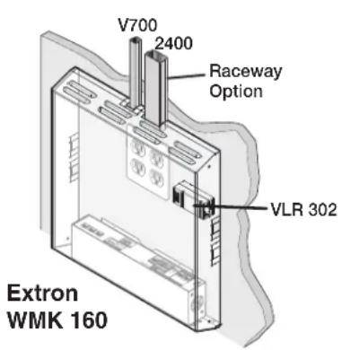

Figure 7. VLR 302 Wall and Ceiling Mounting Options
ZipClip Mounting Kit (optional)
The ZipClip can be mounted on most surfaces, including racks, tables, and lecterns.
Using the ZipClip 400
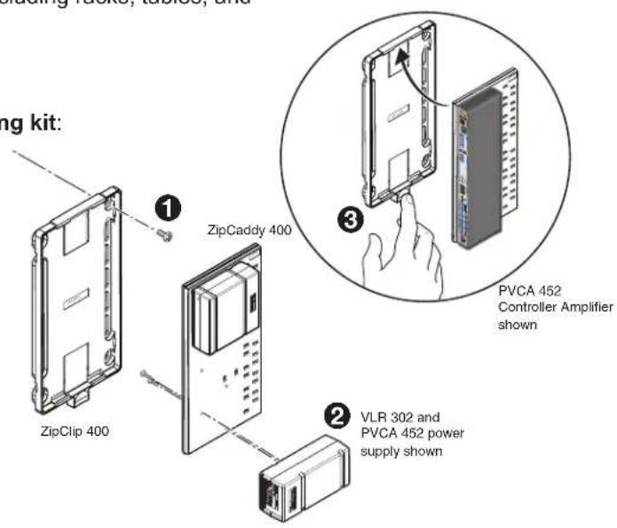
To mount the receiver to a ZipClip 400 mounting kit:
- Install the ZipClip 400 to the rack (①). Rack screws are not provided.
- Secure the VLR 302 and compatible products to the ZipCaddy 400 with the provided #4-40 product mounting screws (②).
- Insert the ZipCaddy 400 onto the ZipClip 400 and snap into place (③). To remove, press down on the ZipClip 400 tab.
Step 2 — Mount the FF 120 Speakers
The FF 120 speakers are installed in ceiling tiles. They receive and output the audio signal from the PVCA 452 or PVS 407D switcher.
Follow the steps below to install the FF 120 speakers.
NOTE: The installation must conform to national and local electrical codes and UL requirements (see the FF 120 Flat Field Speakers User Guide for details).
- Remove and cut ceiling tile — Remove the ceiling tile where the FF 120 will be installed. Cut out a 12-inch section from either end of the tile where the speaker will be installed, as shown below.

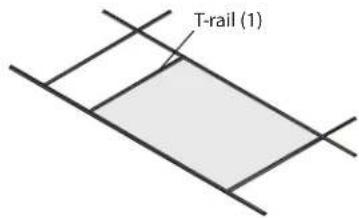
- Install the T-rail — Install the T-rail crosspiece into the ceiling opening up against the cut tile, as shown below.
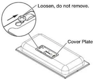
- Cover plate — Loosen, but do not remove, the two screws on the top of the cover plate, as shown on the right. Next, slide and remove the cover plate.
- Using flexible conduit — When using flexible conduit, insert the conduit into the cover plate opening using an appropriate conduit adapter, and secure the conduit adapter to the plate, as shown at right.
When using speaker wires without a conduit, secure the cable clamp adapter (included) to the cover plate and insert the wires through the clamp. Tighten the screws, as shown below.


- Wire the speaker —
a. Pull the wires from the amplifier through and out of the conduit, if a conduit is used.
b. Route the two wires from the amplifier through the cover plate hole.
c. Strip 3/16 inch (5 mm) from the ends of the two speaker wire leads (+ and -) coming from the amplifier. Keep the wire strands together by twisting them (do not tin the wires), and secure the wires to the input terminals of the speaker while observing the correct polarity.
d. Connect the red, positive (+) wire to the + speaker terminal and connect the black, negative (-) wire to the - speaker terminal, as shown at right.

-
Replace the cover plate and tighten the two cover plate screws that were loosened in step 3.
-
Set the speaker on top of a T-rail making sure to hide the edges behind the grid rail, as shown below.

- If secondary support cables are being used, install them (see the illustration below).
ATTENTION:
NOTE: Observe all applicable building codes and local ordinances when installing the speaker.

ATTENTION:
a. Temporarily remove a ceiling tile adjacent to the speaker and set it aside.
b. Connect a secondary support cable through the secondary attachment point, and attach it to one of the tabs located on either side of the speaker.
c. Attach the other end of the cable to a sturdy part of the building (studs, roof struts, and so on).
d. Repeat as needed for additional secondary support cables.
e. Replace the ceiling tile removed in step 8a.
- Check all wiring before powering up the amplifier.
Step 3 — Install the PVCA 452 Controller Amplifier
The PVCA 452 receives input video and audio signals from the display, and audio signals from the VoiceLift VLR 302 receiver. It outputs audio signals to speakers. For details, see the PlanumVault Direct View Systems Installation Guide available at www.extron.com.

Figure 8. PVCA 452 Controller Amplifier
PVCA 452 Installation
- Determine a location within the room where the PVCA 452 will reside.
- Install the PVCA 452, following the instructions in the PlenumVault Direct View Systems Installation Guide and the provided mounting kit user guide.
- Make sure that the PVCA 452 front and rear panels are accessible until installation and testing of the VoiceLift System is complete.
PVCA 452 Location
The controller amplifier can be mounted anywhere in the room. However, placing the PVCA 452 near the ceiling makes cabling and upgrading to a full PlenumVault Direct View System easier. WallVault and ZipClip options are also available for wall or furniture mount applications (for installation instructions, see the installation guides for each system).

WARNING: Structural ceiling failure could cause serious injury or death. Check the structural ceiling to ensure that it can handle a load four times the weight of the final setup.
Possible mounting locations include:
• Table-top, cabinet, or shelf (attach the four provided rubber feet to the bottom of the unit)
- Under a desk
- Mounted to a wall with ZipClips or with an Extron WMK 160
- Above a drop ceiling using the Extron PlenumVault PVM 220
Step 4 — Connect the Receiver and Speakers to the PVCA 452
NOTES:
- Use CATx shielded twisted pair STP cable with T568A or T568B straight-through wiring.
- The connection to the PVCA 452 or PVS 407D switcher powers the receiver, and enables communication and audio between the receiver and the switcher.

- Pull cables to the receiver, along with any other cables that will be attached to the receiver (such as relay connectors).
- Connect the STP cable to the receiver Out (RJ-45) port (see A above).
- Connect the cables to the PVCA 452 or PoleVault switcher as follows:
a. Disconnect the power cable from the PVCA 452 or PoleVault switcher.
b. Plug the STP cable into the VoiceLift RJ-45 port on the switcher (see 3b below).
c. Connect cable from the speakers to the Amplified Audio Out connector on the switcher (see 3c below).
d. Reconnect the power cable to the switcher.

Audio Output to Speakers
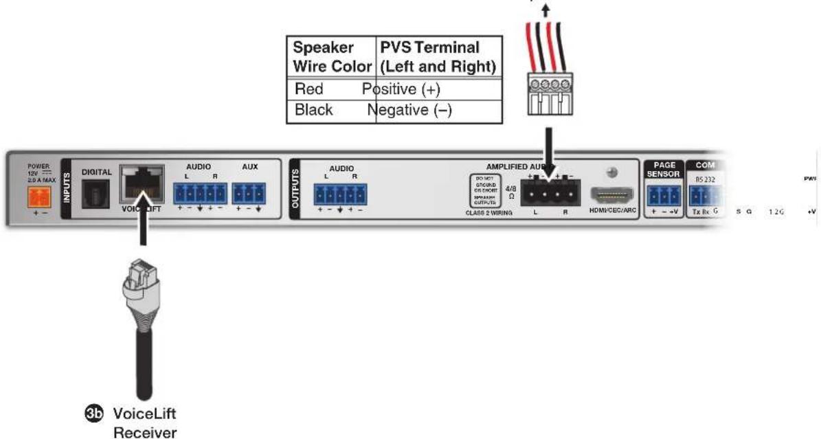
Figure 9. Connecting the Speakers and Receiver to a PVCA 452
Step 5 — Set up the Microphones and Test the System
- Set up each microphone in the VoiceLift system (see Setting up the Microphones on page 13).
- Set the microphone gain:
a. Power on the VoiceLift system. The Power LEDs on the microphone and receiver light green.
b. Instructor: Place the lanyard with the pendant microphone around your neck and adjust the lanyard as shown in step 4 on page 13.
Student: Hold the VLH handheld microphone approximately 4 inches (10.2 cm) from your mouth. Turn off all program audio sources.
c. On the VLP microphone, raise the volume to maximum by pressing and holding the Volume ▲ button. A double beep indicates that maximum volume has been reached. There are five volume steps available.
d. On the PoleVault switcher, while testing the microphone, press the VoiceLift adjust buttons to increase or decrease the microphone input gain. On the PVCA 452, adjust the VoiceLift input gain using PCS software. Adjust the input gain level until an acceptable maximum level is reached. The Signal and Normal LEDs (see image at right) are lit when speaking in a normal voice.
If there is feedback, lower the VoiceLift input gain on the switcher until feedback stops.

Press the VoiceLift buttons to raise or lower the gain
e. Walk around the room while talking into the microphone. If feedback occurs, lower the VoiceLift input gain on the switcher and then walk around the room again, talking into the microphone.
NOTE: The highest gain achieved without feedback is the maximum gain for the VoiceLift system.
f. On the microphone, lower the volume to an appropriate level:
- The level of your speaking voice should be enhanced, but not loud enough to sound like a paging system.
- Check the LEDs on the PVS switcher. The green Normal LED should light when you speak, with the red Peak LED blinking occasionally. Level indicators for the PVCA 452 can be found in PCS software.

Level set too high. Lower input gain.

Level has been properly adjusted.

Signal threshold -20 dBV (-18 dBu)
NOTE: The microphone audio should be slightly audible to the person speaking into it. Have another person listen for the audio levels and check for sound quality.
- Test any optional devices that have been installed.
SIS Configuration and Control
This section provides information on how to configure the VoiceLift system using Extron Simple Instruction Set (SIS) commands. It provides a list and descriptions of the available commands. Topics include:
- Overview
- Host to Receiver Communication
- Commands and Responses
• Command and Response Table for SIS Commands
NOTE: The VoiceLift System can also be configured using the Extron Product Configuration Software (PCS). For full details about using PCS, see the PlenumVault Digital Systems Installation Guide or the PVS 407D PoleVault Digital Switcher User Guide available online at www.extron.com; or see the PCS help file, embedded in the PCS software.
Overview
The VLR 302 receiver can be controlled via a host computer that is connected to the USB control port on the VLR 302 receiver. Commands can be sent from the computer using a communication software program such as Extron DataViewer. SIS commands are available for various functions, such as obtaining information and status for the VLR 302 ports, controlling relay functions, pairing, and resetting the VLR 302.
Host to Receiver Communications
SIS commands consist of one or more characters per field. No special characters are required to begin or end a command sequence. When the VLR 302 recognizes a valid command, it executes the command and sends a response to the host device. All responses from the receiver to the host end the character string with a carriage return and a line feed (CR/LF = ←). A string is one or more characters.
Error Response
When the VLR 302 receives a valid SIS command, it executes the command and sends a response to the host device. If the receiver is unable to execute the command because the command is invalid or contains invalid parameters, it returns the following error response to the host:
E13 - Invalid value (the number is out of range)
Timeout
A pause of 10 seconds or longer between command characters results in a timeout. The command operation is aborted with no other indication.
Commands and Responses
Using the Command and Response Table
The Command and Response Table for SIS Commands on page 27 lists the following:
- Valid ASCII command codes
• The receiver responses to the host - A description of the command function, or the results of executing the command
The ASCII to hexadecimal conversion table below is for use with the command and response table:
| Space → | ASCII to Hex Conversion Table | Esc | 1B | CR | ∅D | LF | ∅A | ||||||||
| 20 | ! | 21 | “ | 22 | # | 23 | $ | 24 | % | 25 | & | 26 | ‘ | 27 | |
| ( 28 ) | ) | 29 | * | 2A | + | 2B | , | 2C | - | 2D | • | 2E | / | 2F | |
| ∅ 30 | 1 | 31 | 2 | 32 | 3 | 33 | 4 | 34 | 5 | 35 | 6 | 36 | 7 | 37 | |
| 8 38 | 9 | 39 | : | 3A | ; | 3B | < | 3C | = | 3D | > | 3E | ? | 3F | |
| @ 40 | A | 41 | B | 42 | C | 43 | D | 44 | E | 45 | F | 46 | G | 47 | |
| H 48 | I | 49 | J | 4A | K | 4B | L | 4C | M | 4D | N | 4E | O | 4F | |
| P 50 | Q | 51 | R | 52 | S | 53 | T | 54 | U | 55 | V | 56 | W | 57 | |
| X 58 | Y | 59 | Z | 5A | [ | 5B | \ | 5C | ] | 5D | ^ | 5E | - | 5F | |
| ` 60 | a | 61 | b | 62 | c | 63 | d | 64 | e | 65 | f | 66 | g | 67 | |
| h 68 | i | 69 | j | 6A | k | 6B | l | 6C | m | 6D | n | 6E | o | 6F | |
| p 70 | q | 71 | r | 72 | s | 73 | t | 74 | u | 75 | v | 76 | w | 77 | |
| x 78 | y | 79 | z | 7A | { | 7B | l | 7C | } | 7D | ~ | 7E | DEL | 7F | |
Upper- and lowercase characters can be used interchangeably in the command field unless otherwise specified.
Symbol Definitions
← = Carriage return and line feed (LF)
← = Carriage return with no line feed
| = Pipe (can be used interchangeably with the ← character).
- = Space
Esc = Escape key
W = Can be used interchangeably with the Esc character.
2 = On and Off status = off/disable/open (default) 1 = on/enable/closed
X3 = Firmware version number
[X4] = Verbose mode
= disabled 2 = tagged responses for queries 1 = verbose mode (default) 3 = verbose mode and tagged responses for queries
X5 = Pulse time in 256 ms counts If parameter is missing or = ∅, then the pulse length is default = 2 (512 ms). Max = 255 (65280 ms ≈ 65 seconds)
X7 = Relay 1 = Relay 1 2 = Relay 2
[X8] = Chime ∅ = Off 1 = On (default)
X9 = Microphone pairing status ∅ = Microphone not occupied, or pairing failed 1 = Link slot occupied 9 = Receiver is unable to enter pairing mode. A previously paired microphone is on and connected; or both Link slots are already occupied.
X10 = Pairing mode status 1 = Pairing initiated 99 = Pairing mode failed; receiver is busy or in use.
X14 = Filter hold duration = indefinite hold 1 through 3600 = adjustment range in seconds
Command and Response Table for SIS Commands
| Command | ASCII Command (Host to Receiver) | Response (Receiver to Host) | Additional Description |
| Status | |||
| View microphone usage (hours) | EscUSAG← UsagXXXXX:XX | ← | Format is in number of hours and minutes (HHHHH:MM). Maximum character limit for hours is five digits (ex. XXXXX:XX). Minutes are in increments of 15. Maximum value is "99999:45" |
| Reset microphone usage | Esc0USAG← Usag00000:00 | ← | |
| NOTE: Maximum hours up to five characters (ex. 12345:15). | |||
| Relay Functions | |||
| Pulse relay | X7*3*X50 Rly | X7*X2← | |
| Toggle relay | X7*20 Rly | X7*X2← | |
| Force relay ON | X7*10 Rly | X7*1← | |
| Force relay OFF | X7*00 Rly | X7*0← | |
| View relay state | X70 Rly | X7*X2← | |
| Chime | |||
| Set audible chime | EscX8CHIM← Chim | X8← | |
| View audible tone | EscCHIM← Chim | X8← | |
| Pairing | |||
| Initiate pairing mode | Esc1PAIR← Pair | X10← | |
| View paired | EscPAIR← Pair | X9X9← | "View Paired" response indicates whether microphones are paired to each Link slot. The first X9 variable represents Link slot 1; the second X9 variable represents Link slot 2. For example, "Pair11" Indicates that microphones are paired to both Link slots 1 and 2. |
| Clear paired | Esc0PAIR← Pair0 | ← | |
| Verbose Mode | |||
| Set verbose mode | EscX4CV← Vrb | X4← | |
| View verbose mode | EscCV← Vrb | X4← | |
| Reset | |||
| Reset Esc ZXXX← Zpx | ← | ||
| Information Requests | |||
| Request part number | N | 60-1637-01VL← | Show part number of the VLR 302 receiver. |
| Query firmware version | Q or 1Q | X3← | Show the VLR 302 firmware version (X3) to two decimal places. |
| Example: | Q | 1.01← | |
| Query updated firmware version | 20Q | X3← | Show the version of firmware that was uploaded by the user to the receiver. |
| Request model name | 1I | VLR·302← | Show the receiver product name. |
| Feedback Suppressor | |||
| Set feedback suppressor | EscX2FSEN← Fsen | X2← | Response indicates if feedback suppression is enabled or disabled. |
| View feedback suppressor | EscFSEN← Fsen | X2← | Response indicates if feedback suppression is enabled or disabled. Default is ∅ (Off). |
| Filter hold | |||
| Set filter hold time | EscX14FHLD← Fhld | X14← | Response indicates filter hold time in seconds (setting is global to all 15 filters). |
| View filter hold time | EscFHLD← Fhld | X14← | Response indicates filter hold time in seconds. Default is 3600 (60 minutes). |
Reference Information
This section provides the following reference information:
- Updating Firmware with Firmware Loader
- Resetting the VLR 302
Updating Firmware with Firmware Loader
To upload and update firmware for the VLR 302, download the new firmware to a connected computer and upload the firmware with the Extron Firmware Loader utility.
Downloading Extron Firmware Loader
- On the Extron website, go to the Download tab and click Software (see figure 10, ①, below).
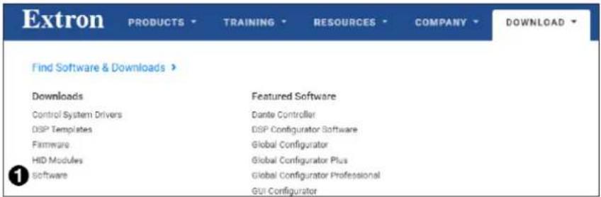
Figure 10. Downloading Software from the Extron Website
- Navigate to Firmware Loader (see figure 11, ①).
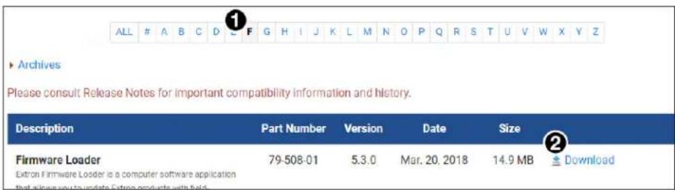
Figure 11. Downloading Firmware Loader on the Extron Website
- Click the Download link on the right that corresponds with the program (see figure 11, ②).
- Submit any required information to start the download.
Installing Firmware Loader
- Once Firmware Loader has been downloaded, run the .exe file from the location where the file was saved. The installation window opens.
- Follow the instructions on the installation screens to install Firmware Loader on the computer.
Downloading Firmware

Figure 12. Downloading Firmware from the Extron Website
- On the Extron website, go to the Download tab and click Firmware (see figure 12, ①).
- Navigate to VLR 302.
- Ensure the available firmware version is a later version than the current one on the device.
NOTE: The firmware release notes are a PDF file that provides details about the changes between different firmware versions. The file can be downloaded from the same page as the firmware.
- Click the Download link to the right of the desired device.
- Submit any required information to start the download. Note where the file is saved.
- Run the executable file (.exe file extension) and follow the on-screen instructions to place the firmware file and release notes on the PC. Note where the file is saved.
Installing Firmware with Firmware Loader
- Connect the host device to the front panel USB port.
- Open Firmware Loader and establish a connection between the computer and the device. The Add Device... dialog box opens.
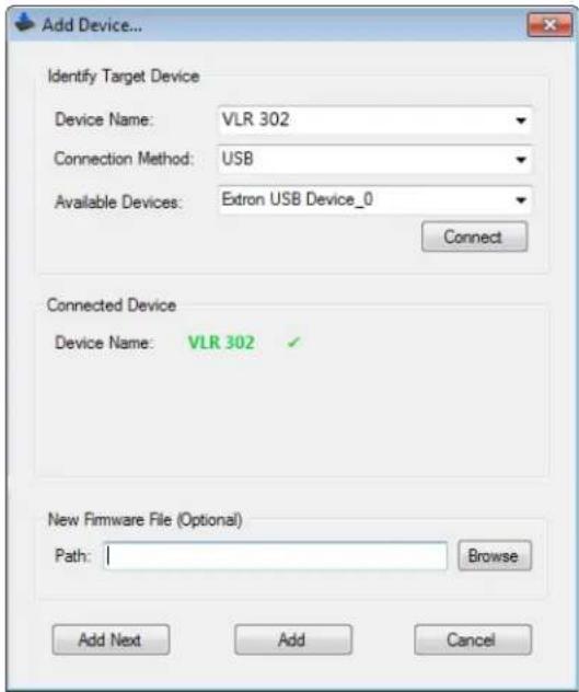
Figure 13. Add Device... Dialog Box
- From the Device Name drop-down list, select VLR 302.
-
From the Connection Method drop-down list, select USB.
-
Make the appropriate device selection for the current connection method.
- Click the Connect button.
- In the New File Firmware (Optional) panel, click Browse. The Open dialog box opens.
- In the Open dialog box, navigate to the location of the new firmware file and select the desired file.
ATTENTION:
- Valid firmware files must have the file extension .S19. A file with any other extension is not a firmware upgrade for this device and could cause the device to stop functioning.
-
Les fichiers firmware valides doivent contenir l'extension fichier S19. Un fichier avec n'importe quelle autre extension n'est pas une mise à jour de firmware pour cet appareil et l'appareil pourrait arrêter de fonctionner.
-
Click Open. The Browse dialog box closes.
-
Click Add. The Add Device... dialog box closes and the device and firmware are listed in the Firmware Loader main window.
- Click Begin to start the upload process.
- Close Firmware Loader when the Remaining Time field shows 00:00:00, the Progress column shows 100%, and the Status field shows completed.
Resetting the VLR 302
Follow the steps below to reset the VLR 302 receiver using the front panel Reset button (see A on page 11). The VLR 302 may also be reset using the Product Configuration Software (see the help file for the VLR 302 module within PCS).
NOTE: All paired microphones must be turned off in order to properly reset the VLR 302 receiver.
Reset Mode 1
This mode resets the unit to its base factory firmware.
Hold down the Reset button while the switcher is being powered up. The receiver boots to its base factory firmware. Any firmware that has been loaded over the base firmware is ignored.
Reset Mode 2
This mode resets pairing history, but retains settings and usage data.
- Hold down the Reset button for about three seconds until the Power LED blinks once.
- Release and press the Reset button momentarily (for less than one second) within one second.
- Both Link 1 and Link 2 LEDs blink one time, simultaneously, to confirm that the pairing history has been cleared. Unsolicited response "Pair00" is sent.
Reset Mode 3
This mode is an absolute factory reset. It will reset the unit to factory default settings, and also clear pairing and usage data.
- Hold down the Reset button for about six seconds until the Power LED blinks two times.
- Release and press the Reset button momentarily (for less than one second) within one second.
Front panel LEDs cycle, and all settings (including pairing history) are cleared from the unit. This reset is the same as sending the 'ZXXX' SIS command.
Extron Warranty
Extron warrants this product against defects in materials and workmanship for a period of three years from the date of purchase. In the event of malfunction during the warranty period attributable directly to faulty workmanship and/or materials, Extron will, at its option, repair or replace said products or components, to whatever extent it shall deem necessary to restore said product to proper operating condition, provided that it is returned within the warranty period, with proof of purchase and description of malfunction to:
USA, Canada, South America, and Central America:
Extron
1230 South Lewis Street
Anaheim, CA 92805
U.S.A.
Asia:
Extron Asia Pte Ltd
135 Joo Seng Road, #04-01
PM Industrial Bldg.
Singapore 368363
Singapore
Japan:
Extron Japan
Kyodo Building, 16
Ichibancho
Chiyoda-ku, Tokyo 102-0082
Japan
Europe:
Extron Europe
Hanzeboulevard 10
3825 PH Amersfoort
The Netherlands
China:
Extron China
686 Ronghua Road
Songjiang District
Shanghai 201611
China
Middle East:
Extron Middle East
Dubai Airport Free Zone
F13, PO Box 293666
United Arab Emirates, Dubai
Africa:
Extron South Africa
3rd Floor, South Tower
160 Jan Smuts Avenue
Rosebank 2196, South Africa
This Limited Warranty does not apply if the fault has been caused by misuse, improper handling care, electrical or mechanical abuse, abnormal operating conditions, or if modifications were made to the product that were not authorized by Extron.
NOTE: If a product is defective, please call Extron and ask for an Application Engineer to receive an RA (Return Authorization) number. This will begin the repair process.
USA: 714.491.1500 or 800.633.9876 Asia: 65.6383.4400
Europe: 31.33.453.4040 or 800.3987.6673
Japan: 81.3.3511.7655
Africa: 27.11.447.6162
Middle East: 971.4.299.1800
Units must be returned insured, with shipping charges prepaid. If not insured, you assume the risk of loss or damage during shipment. Returned units must include the serial number and a description of the problem, as well as the name of the person to contact in case there are any questions.
Extron makes no further warranties either expressed or implied with respect to the product and its quality, performance, merchantability, or fitness for any particular use. In no event will Extron be liable for direct, indirect, or consequential damages resulting from any defect in this product even if Extron has been advised of such damage.
Please note that laws vary from state to state and country to country, and that some provisions of this warranty may not apply to you.
- VoiceLift Pro Microphones
- Safety Instructions • English
- FCC Compliance Statement
- Canada Compliance Statement
- Conventions Used in this Guide
- Notifications
- Software Commands
- Specifications Availability
- Extron Glossary of Terms
- Contents
- Introduction....1
- VLM Kit Installation and Operation....6
- VoiceLift System Installation....17
- SIS Configuration and Control....25
- Reference Information 28
- Introduction
- About this Guide
- About the VoiceLift Pro Microphone Kits (VLM Kits)
- NOTES:
- About the VoiceLift System (VLS)
- VLM Kits
- VoiceLift Pro Microphone Features
- Application Diagram
- VLM Kit Installation and Operation
- VoiceLift Pro Microphone Kit Overview
- Installing the VLC 302 Charger and Charging the Microphones
- ATTENTION:
- Installing the VLR 302 Receiver
- Feedback Suppression
- Connections
- Setting up the Microphones
- VLP 302 Pendant Microphone
- VLH 302 Handheld Microphone
- Saving the Microphone Volume
- Pairing the Microphones with the VLR 302
- Verify which Microphones are Paired
- Pair New Microphones
- • For the VLH 302:
- Setting up VLP 302 Instant Alerts
- Tips for Using the Microphones
- Recommended Installation Tools
- Other Hardware Items
- Step 1 — Mount the VLR 302 Receiver
- Rack Mounting
- UL Guidelines for Rack Mounting
- Rack Mounting Procedure
- Back of the Rack Mounting Procedure
- Wall and Ceiling Mounting
- ZipClip Mounting Kit (optional)
- Using the ZipClip 400
- To mount the receiver to a ZipClip 400 mounting kit:
- Step 2 — Mount the FF 120 Speakers
- Step 3 — Install the PVCA 452 Controller Amplifier
- PVCA 452 Installation
- PVCA 452 Location
- Step 4 — Connect the Receiver and Speakers to the PVCA 452
- Step 5 — Set up the Microphones and Test the System
- SIS Configuration and Control
- Overview
- Host to Receiver Communications
- Error Response
- Timeout
- Commands and Responses
- Using the Command and Response Table
- Symbol Definitions
- Reference Information
- Updating Firmware with Firmware Loader
- Downloading Extron Firmware Loader
- Installing Firmware Loader
- Downloading Firmware
- Installing Firmware with Firmware Loader
- Resetting the VLR 302
- Reset Mode 1
- Reset Mode 2
- Reset Mode 3
- Extron Warranty
- USA, Canada, South America, and Central America:
- Asia:
- Japan:
- Europe:
- China:
- Middle East:
- Africa:
Brand : Extron
Model : VoiceLift Pro Microphone
Category : Microphone