
SF 10C SUB - Subwoofer Extron - Free user manual and instructions
Find the device manual for free SF 10C SUB Extron in PDF.


| Product Type | Subwoofer |
| Brand | Extron |
| Model | SF 10C SUB |
| Driver Size | 10 inches (254 mm) |
| Frequency Response | 25 Hz to 160 Hz (-10 dB, half space) |
| Power Handling (Program) | 800 watts continuous program |
| Power Handling (Continuous Pink Noise) | 400 watts (IEC 60268-5) |
| Impedance | 8 ohms |
| Enclosure Type | 4th order band-pass with tuned bass-reflex port |
| Enclosure Material | Rigid composite, paintable |
| Plenum Rating | UL 2043 listed for air-handling spaces |
| Mounting Options | Suspension above ceiling (included cables), optional floor mount kit (SMK F SF 10C Plus) |
| Included Accessories | 4 x 15 ft steel cables with locking adapters, C-ring, paintable grille, amplifier mounting kit |
| Weight | Approximately 38 lb (17 kg) |
| Warranty | 5 years parts and labor |
| Compliance | FCC Class A, VCCI-A, UL 2043 |
| Port Type | Right-angle port for directed sound |
| Amplifier Compatibility | Any Extron low impedance amplifier; can mount NetPA U or XPA U directly |
| Crossover Requirement | Not required when used with SF 26CT, SF 3C LP, or SF 3CT LP ceiling speakers |
| Safety Features | Integrated flame arrester, isolation grommets |
Frequently Asked Questions - SF 10C SUB Extron
User questions about SF 10C SUB Extron
0 question about this device. Answer the ones you know or ask your own.
Ask a new question about this device
Download the instructions for your Subwoofer in PDF format for free! Find your manual SF 10C SUB - Extron and take your electronic device back in hand. On this page are published all the documents necessary for the use of your device. SF 10C SUB by Extron.
USER MANUAL SF 10C SUB Extron
natural_image
Close-up of a cylindrical industrial component with meshed top and mounting flanges (no visible text or symbols)Extron
Safety Instructions
Safety Instructions • English

WARNING: This symbol, 4 when used on the product, is intended to alert the user of the presence of uninsulated dangerous voltage within the product's enclosure that may present a risk of electric shock.
ATTENTION: This symbol, when used on the product, is intended to alert the user of important operating and maintenance (servicing) instructions in the literature provided with the equipment.
For information on safety guidelines, regulatory compliances, EMI/EMF compatibility, accessibility, and related topics, see the Extron Safety and Regulatory Compliance Guide, part number 68-290-01, on the Extron website, www.extron.com.
All trademarks mentioned in this guide are the properties of their respective owners. The following registered trademarks (®) and registered service marks (™) are the property of RGB Systems, Inc. The trademarks (™) are the property of RGB Systems, Inc. or Extron (see the current list of trademarks on the Terms of Use page at www.extron.com):
| Registered Trademarks (®) |
| Extron, Cable Cubby, ControlScript, CrossPoint, DTP, eBUS, EDID Manager, EDID Minder, eLink, Flat Field, FlexOS, Glitch Free, Global Configurator, Global Scripter, GlobalViewer, Hideaway, HyperLane, IP Intercom, IP Link, Key Minder, LinkLicense, LockIt, MediaLink, MediaPort, NAV, NetPA, PlenumVault, PoleVault, PowerCage, PURE3, Quantum, ShareLink, Show Me, SoundField, SpeedMount, SpeedSwitch, StudioStation, System INTEGRATOR, TeamWork, TouchLink, V-Lock, VideoLounge, VN-Matrix, VoiceLift, WallVault, WindoWall, XPA, XTP, XTP Systems, and ZipClip |
| Registered Service Mark ^(SM) : S3 Service Support Solutions |
| Trademarks ^(TM) |
| AAP, AFL (Accu-RATE Frame Lock), ADSP (Advanced Digital Sync Processing), Auto-Image, AVEdge, CableCover, CDRS (Class D Ripple Suppression), Codec Connect, DDSP (Digital Display Sync Processing), DMI (Dynamic Motion Interpolation), Driver Configurator, DSP Configurator, DSVP (Digital Sync Validation Processing), EQIP, Everlast, FastBite, Flex55, FOX, FOXBOX, IP Intercom HelpDesk, MAAP, MicroDigital, Opti-Torque, PendantConnect, ProDSP, QS-FPC (QuickSwitch Front Panel Controller), Room Agent, Scope-Trigger, SIS, Simple Instruction Set, Skew-Free, SpeedNav, Triple-Action Switching, True4K, True8K, Vector ^TM 4K, WebShare, XTRA, and ZipCaddy |
FCC Class A Notice
This equipment has been tested and found to comply with the limits for a Class A digital device, pursuant to part 15 of the FCC rules. The Class A limits provide reasonable protection against harmful interference when the equipment is operated in a commercial environment. This equipment generates, uses, and can radiate radio frequency energy and, if not installed and used in accordance with the instruction manual, may cause harmful interference to radio communications. Operation of this equipment in a residential area is likely to cause interference. This interference must be corrected at the expense of the user.
NOTE: For more information on safety guidelines, regulatory compliances, EMI/EMF compatibility, accessibility, and related topics, see the Extron Safety and Regulatory Compliance Guide on the Extron website.
VCCI-A Notice
Conventions Used in this Guide
Notifications
The following notifications are used in this guide:

WARNING: Potential risk of severe injury or death.
CAUTION: Risk of minor personal injury.
NOTE: A note draws attention to important information.
TIP: A tip provides a suggestion to make working with the application easier.
Specifications Availability
Product specifications are available on the Extron website, www.extron.com.
Extron Glossary of Terms
A glossary of terms is available at http://www.extron.com/technology/glossary.aspx.
Contents
Introduction.... 1
About this Guide....1
About the SF 10C SUB .... 1
Features 2
Installation......4
Placement Considerations and Acoustical Reinforcement....4
Installation Environment 4
Acoustical Reinforcement 5
Mounting the Subwoofer 6
Suspending in the Ceiling 6
Installing Long Legs for Vertical Installation on a Floor....10
Installing Short Legs for Horizontal Installation on a Floor....13
Mounting the Port Tube 14
Installing the Grille....14
Connection and Operation....16
Connection....16
Operational Considerations....19
Mounting a NetPA U or XPA U Amplifier to the SF 10C SUB....19
Troubleshooting....23
Introduction
- About this Guide
• About the SF 10C SUB - Features
About this Guide
This guide describes the Extron SF 10C SUB, a subwoofer, that is typically installed above a suspended ceiling. This guide describes how to install, operate, and configure the subwoofer.
About the SF 10C SUB
The SF 10C SUB (see figure 1 on the next page) is a plenum-rated, 8 ohm, 4th order band-pass subwoofer with a tuned bass-reflex port. When installed, the subwoofer is typically suspended by wires from the structural ceiling above the suspended ceiling. This avoids unwanted rattling and vibrating in the ceiling tile grid. It features a 10-inch ported woofer housed within a cylindrical enclosure. A right-angle port on the front of the enclosure directs the sound waves into the listening area.
The subwoofer has a frequency range of 25 Hz to 160 Hz, -10 dB, half space.
The SF 10C SUB is compatible with any Extron low impedance amplifier with sufficient output drive power. The unit is UL 2043 Listed for use in air-handling spaces.
The subwoofer is intended for use in a bi-amplified system. Separate amplifiers should power the low and high frequencies.
ATTENTION:
Figure 1. Typical SF 10C SUB Application
Features
- 10-inch (254 mm) low frequency driver with a tuned port — Designed specifically for low frequency extension.
- UL 2043 rated, rigid composite enclosure — Enclosure remains out of view when suspended above the ceiling grid.
• Frequency range: 25 Hz to 160 Hz - 800 watts continuous program 400 watts continuous pink noise — Power capacity per IEC 60268-5
- 8 ohm operation — Direct low impedance power avoids low frequency transformer distortion.
- Suspension mounting above the ceiling structure greatly reduces rattle — Because the unit is physically isolated from the ceiling grid, low frequency vibrations are not transferred to loose structural components.
- 4th order bandpass enclosure design — High output with controlled and clean low frequency extension
-
No crossover needed when used with SF 26CT, SF 3C LP, or SF 3CT LP ceiling speakers — Eliminates phase problems at a crossover point.
-
Includes installation and suspension hardware — Four sets of 15-foot (4.6 m) steel cables with locking adapters are used to raise the SF 10C SUB into place and suspend it.
- Includes mounting hardware for NetPA Ultra and XPA Ultra power amplifiers
- Includes C-ring and paintable grille — Port output into the room blends in with ceiling speakers.
- Paintable enclosure — The SF 10C SUB enclosure can be painted with a plastic-friendly paint.
- Integrated flame arrester for safety — Restricts flammability for plenum installations.
- Optional floor mounting kit — The SMK F SF 10C Plus kit provides legs for both vertical and horizontal mounting of the SF 10C SUB to a solid surface.
- 5-year parts and labor warranty
Installation
This section describes the installation and the operation of the SF 10C SUB, including:
- Placement Considerations and Acoustical Reinforcement
- Mounting the Subwoofer
- Mounting the Port Tube
• Installing the Grille
• Connection and Operation - Mounting a NetPA U or XPA U Amplifier to the SF 10C SUB
- Troubleshooting
Placement Considerations and Acoustical Reinforcement
Installation Environment
Ceiling placement
- The speaker is rated for installation in plenum spaces.
- The mounting kit comes with four sets of aircraft cables and cable gripper mounting hardware for suspending the speaker in a horizontal orientation.
-
Mounting holes for mounting using unistruts or all thread rods are provided.
-
Isolation grommets are provided that dampen mechanical vibrations from the subwoofer to the rest of the structure.
- Other than the isolation grommets, the installer must provide the mounting hardware for unistrut or all thread rod installation.
- The mounting holes can also accept hanger wire.
- The port tube does not isolate the listening space from the installation space. Bleed-over into adjacent rooms must be taken into consideration.
Placement behind a wall
- When the subwoofer is installed behind a wall, the port tube must be located as close to the wall surface facing the listening space as possible.
- The drywall facing the subwoofer may need to be removed between the studs on either side of the unit, in order to bring the port tube as close as possible to the front surface of the wall. In this case, fire blocks must be run in-between the studs, to seal off the space above the removed portion of the wall.
- The optional SMK F SF 10C Plus floor mounting kit must be used when the subwoofer is placed on the floor and must be strapped to a stud.
Acoustical Reinforcement
Depending on where you mount the subwoofer, such as next to a large, rigid, planar surface, you can achieve some level of acoustical reinforcement (see figure 2).
NOTE: At the frequencies at which the subwoofer operates, fiberglass ceiling tiles are acoustically transparent and offer little acoustical reinforcement.
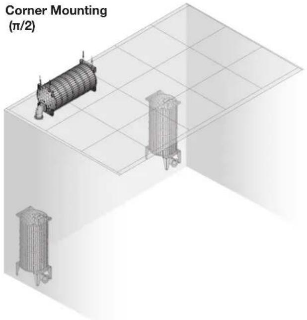
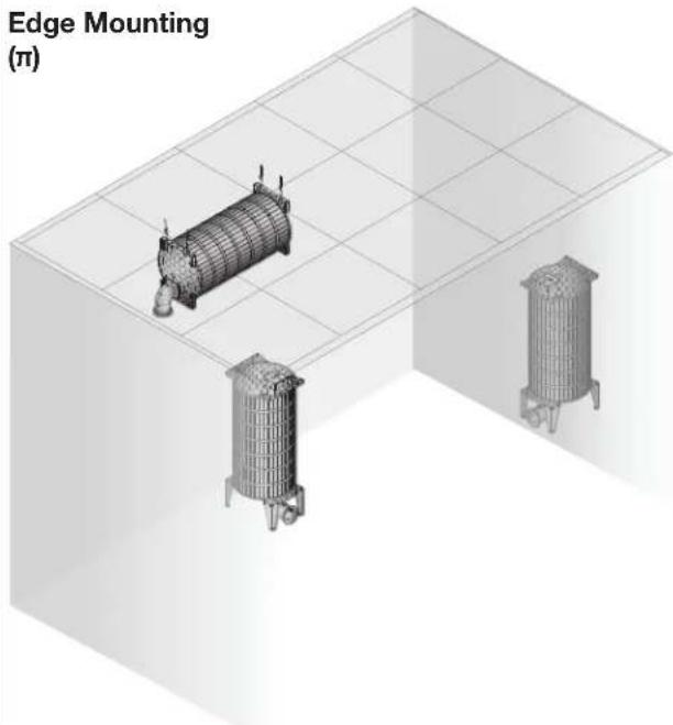
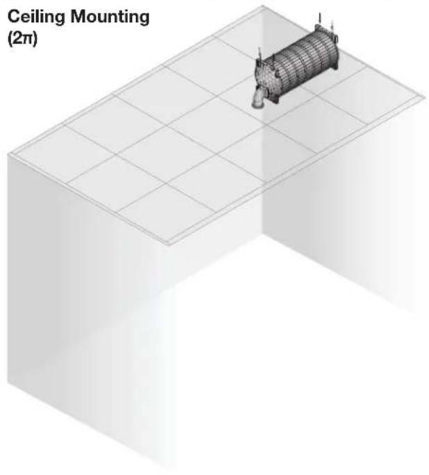
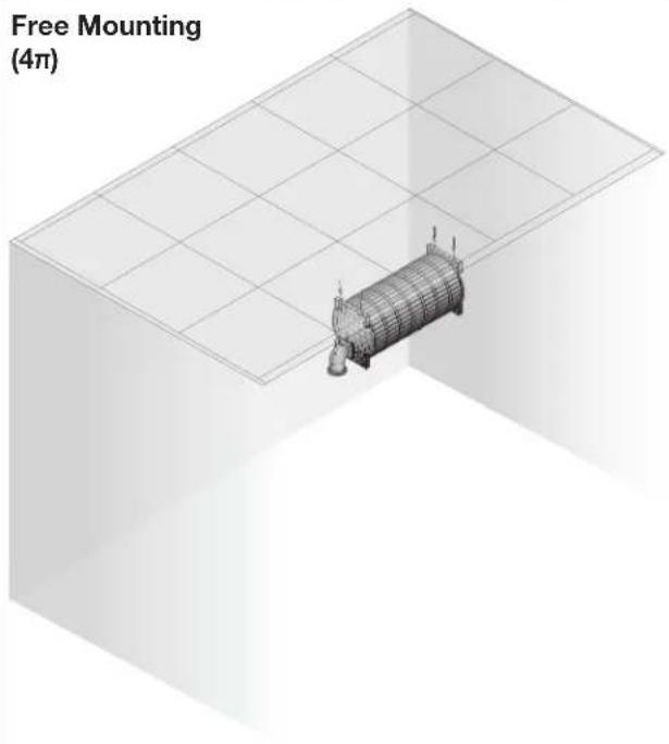
Figure 2. Mounting Locations with Regards to Acoustical Reinforcement
- Corner mounting (see figure 2 on the previous page) — The subwoofer is mounted in a corner of a surface where three surfaces meet, giving reinforcement from all three surfaces. This option provides the most reinforcement. The port tube should be as close to the corner as possible for best results.
- Edge mounting (figure 2) — The subwoofer is mounted at the edge of a surface where two surfaces meet, giving reinforcement from both surfaces. This option is as much as 6 dB less sensitive than corner mounting. The port should be as close to the edge as possible for best results.
- Ceiling, wall, or floor mounting (figure 2) — The subwoofer is mounted in or on a surface in an area away from any other surface. This option is as much as 12 dB less sensitive than corner mounting. There is reinforcement from only one surface.
- Free mounting (figure 2) — The subwoofer is mounted away from all walls, the floor and the ceiling. This option is as much as 18 dB less sensitive than corner mounting. There is no reinforcement from any surface.
Mounting the Subwoofer
The SF 10C SUB can be suspended in a ceiling or rested on the floor.
Suspending in the Ceiling

WARNING:
AVERTISSEMENT :
The subwoofer can be suspended using the included aircraft cables (see "Aircraft cable installation") or, optionally, with threaded rods acquired locally (see Threaded rod installation on page 10).
Aircraft cable installation
Suspend the subwoofer above a false ceiling using the included aircraft cables as follows:
Remove ceiling tile and install suspension cables.
For installation with optional threaded rods, see Threaded rod installation.
- Determine where the subwoofer is to be suspended and its orientation above the suspended ceiling.
NOTE: Remember that the sound from the unit is directed out the port. Therefore, although you can suspend the subwoofer in any horizontal orientation, the port needs to be pointed into the listening space.
Consider the following as you make this determination:
• Possible acoustical reinforcement (see Acoustical Reinforcement on page 5).
- The size (length, width, and height) of the subwoofer.
- The desired location of the woofer port. Ensure that the center of the port tube will be at least 5-3/16 inches (13.7 cm) from the edge of suspended ceiling tile once that tile is installed.
NOTE: This positioning ensures that the grille adapter and C-ring fit properly once installed (see figure 3).
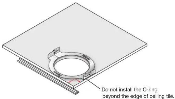
Figure 3. Grille Adapter and C-ring Fit
- Any obstructions above the suspended ceiling that could constrain the orientation of the suspended subwoofer.
- At the location where the subwoofer is to be installed, remove as many ceiling tiles as necessary to install the subwoofer.
NOTE: The number of tiles to remove depends on the height of the structural ceiling above the suspended ceiling, given the 10-degree spread from the subwoofer to the structural ceiling.
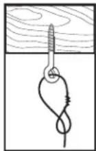
At an approximate angle of 10 degrees out from each corner of where the subwoofer will be installed, mark and drill four holes in the structural ceiling for the suspension cable anchors.
-
Screw a lag eye bolt (or an appropriate anchor) into each hole.
-
Thread the loose end of the suspension cable through the bolt eyehole, pass the loose end of the cable through the looped end and tighten. Allow each cable to hang.
Suspend the main subwoofer enclosure from the ceiling
ATTENTION: The SF 10C SUB is heavy, approximately 38 pounds (17 kg), and bulky.
TIP: If a scissor-lift is not available, the speaker can be hoisted using the suspension cables.
- Remove the grommets from all four corners of the subwoofer frame (see figure 4 on the next page).
- Install the included eyebolts into the four holes on the four corners of the subwoofer frame. Secure the eyebolts in place with the provided locking nuts (figure 4).
- With the help of at least one other person, carefully lift the subwoofer enclosure into the installation location.
- Holding a cable gripper, pass the loose end of one of the cables down through one hole of the gripper. Ensure that about 12 to 15 inches (30 to 38 cm) of cable has exited the gripper (figure 4).

WARNING:
AVERTISSEMENT :
Figure 4. Installing the Subwoofer with the Included Steel Cables
- Pass the loose end of the cable through one of the eye bolts on the subwoofer enclosure and then through the other hole in the cable gripper. Ensure that at least 1 inch (25 mm) of cable comes through the other end of the gripper.
-
Repeat steps 4 and 5 for each corner.
-
Adjust the cable tension through all cable grippers so that the subwoofer appears level to the critical eye and to ensure that its bottom brackets will be approximately 1 inch (2.5 cm) from the top surface of suspended ceiling tile once that tile is installed.
NOTE: The exact height of the subwoofer is not critical at this point. You will make final adjustments after the grille is installed.
Threaded rod installation
Secure the subwoofer to the structural ceiling using threaded rods as follows:
NOTES:
- Extron recommends 1/4-inch or 3/8-inch diameter threaded rods for installing this product.
-
The threaded rod must be properly secured to the ceiling structure. For example, properly fasten a unistrut to the ceiling structure and attach threaded rods using nuts and fender washers.
-
Fasten four threaded rods to the support structure. Extron recommends fastening the rods to unistruts, one over each corner of the subwoofer installation location.
- Fasten a rod to each corner securing point of the subwoofer with nuts and fender washers (see the figure at right).
- Adjust all the nuts that secure the subwoofer to the ceiling so that the subwoofer appears level to the critical eye and to ensure that its bottom brackets will be approximately 1 inch (2.5 cm) from the top surface of suspended ceiling tile once that tile is installed.
NOTE: The exact height of the subwoofer above the ceiling is not critical at this point. You will make final adjustments after the grille is installed.
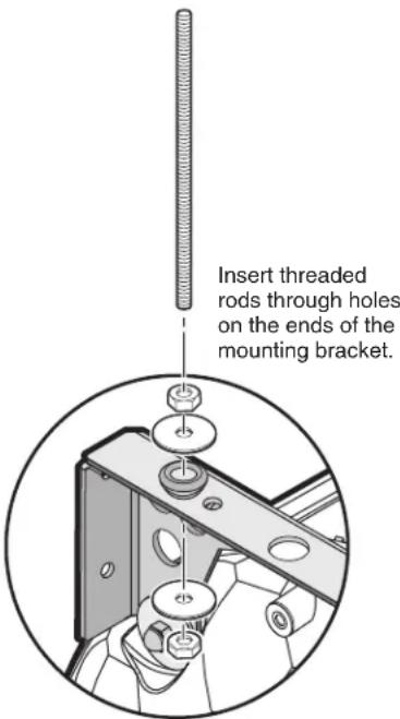
Attach washer and nut and secure.
Installing Long Legs for Vertical Installation on a Floor
ATTENTION:
The subwoofer can be set vertically on a floor using the optional SMK F SF 10C Plus floor mounting kit, as follows:
- Determine where the subwoofer is to be placed and its orientation (port tube on top or port tube on the bottom).
NOTES:
- Remember that the sound from the unit is directed out the port. Therefore, the port needs to be pointed into the listening space.
- To ensure that the Extron grille fits fully into any masking wall or other partition, the center of the port tube must be at least 5-3/16 inches (13.7 cm) from the edge of the wall.
- The included grille does not fit if you install the legs on the subwoofer with the port tube down and place the feet directly on the floor. Consider fabricating a small platform to lift the subwoofer or otherwise design your own way to dress the installation to give your installation a finished look (see figure 6, ③, on the next page).
-
Steps 4, 5, 6, and 9 are necessary only if you are installing the subwoofer in an adjoining space.
-
Remove the grommets from the holes in the installation bracket.
- Fasten two legs to each installation bracket using the provided screws and locking nuts, two on one side of the foot (see figure 5, ①), and one on the other side (②).
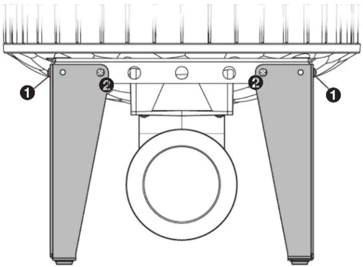
Figure 5. Installing a Floor Mounting Kit
- When installing in an adjoining space — On the far side of the wall (outside the listening space), remove enough wall material so that the subwoofer port tube can be placed as close to the wall (facing the listening space) as possible.
- When installing in an adjoining space — On the near side of the wall (inside the listening space), using the included grille cut-out template, mark where the center of the port tube faces the installation surface. The center mark must be at least 5-3/16 inches (13.2 cm) from the edge of the installation surface (see figure 3 on page 7) if the grille will be used (see Installing the Grille on page 14).
- When installing in an adjoining space — On the near side of the wall (inside the listening space), mark and cut the hole in the surface.
-
Place the subwoofer in the desired location.
-
Use the included nylon straps and included accessories, or locally-obtained perforated metal hanger straps, to secure two of the mounting holes on the top bracket to the nearest stud or other stationary surface (see figure 6, ①). Use locally obtained hardware suitable for the material to which the unit is being secured.
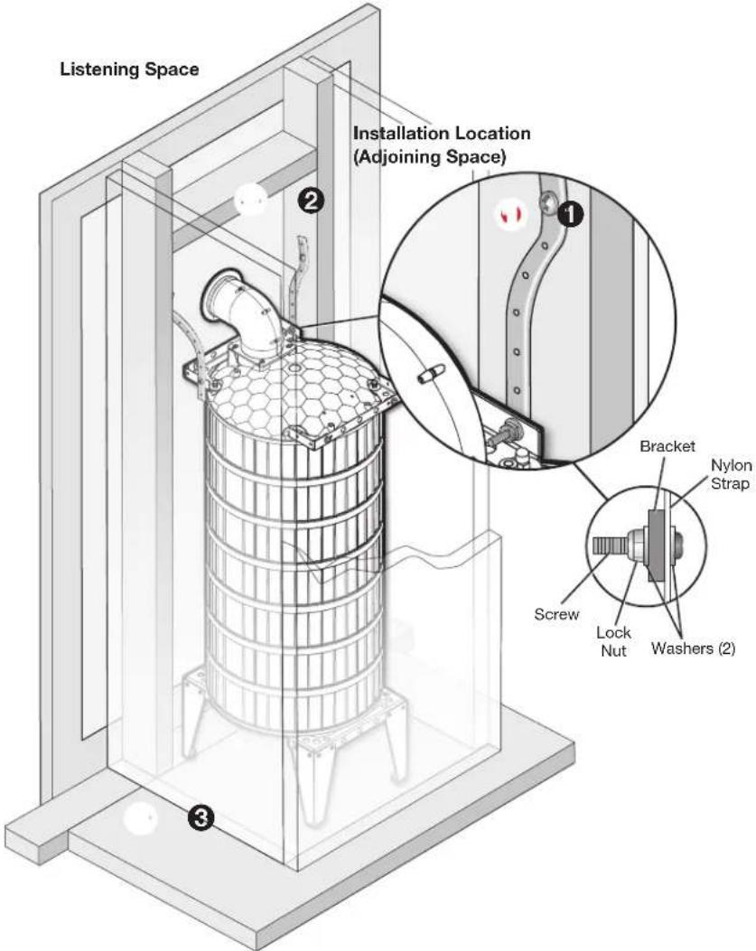
Figure 6. Securing the Floor-mounted Subwoofer and Installing Fire Breaks
- When installing in an adjoining space — Ensure that there are fire breaks above and below the port tube (2) to meet UL requirements. Fabricate them if necessary.
Installing Short Legs for Horizontal Installation on a Floor
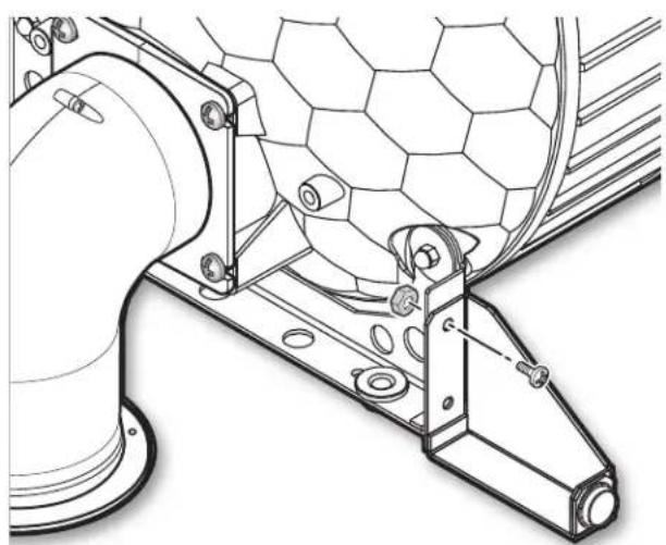
The subwoofer can be set horizontally on a floor using the optional SMK F SF 10C Plus floor mounting kit, as follows:
- Fasten a foot to each installation bracket using the provided screws and locking nuts (see figure 7 and figure 8).
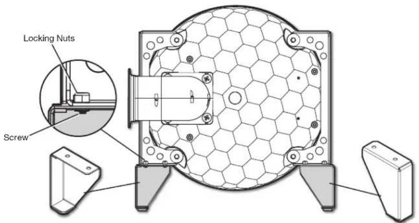
Figure 7. Short Leg Installation
natural_image
Technical line drawing of a mechanical assembly with hexagonal mesh components and mounting brackets (no text or symbols)Figure 8. Attaching the Foot
- Place the subwoofer in the desired location.
Mounting the Port Tube
- Orient the port tube so that it is pointed into the listening space.
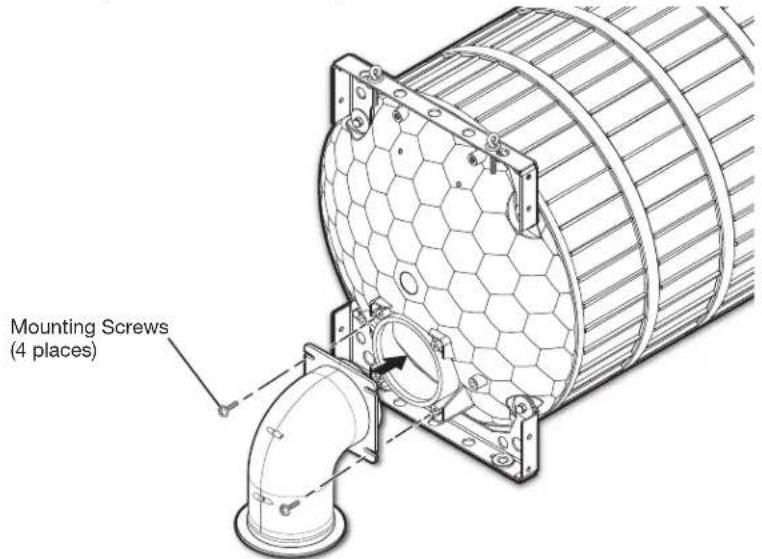
Figure 9. Installing the Port Tube
- Using the included hardware, mount the port tube to the speaker (see figure 9).
Installing the Grille
NOTE: For ceiling tile installation, if the ceiling tile is not removed for the subwoofer installation, remove it.
- If not already accomplished, on the installation surface, mark where the center of the port tube faces the installation surface. The center mark must be at least 5-3/16 inches (13.2 cm) from the edge of the installation surface.
- If not already accomplished, using the included grille cut-out template, mark and cut the hole in the surface.
- For ceiling tile installation, replace the ceiling tile in the grid.
-
Place the C-ring on the subwoofer side of the installation surface and center it over the hole.
-
Place the grille adapter on the opposite side of the installation surface (see figure 10) and use a Phillips screwdriver to turn the three locking arms to loosely mate the adapter to the C-ring.
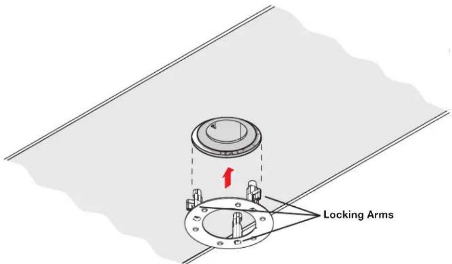
Figure 10. Installing the Grille Adapter
-
Rotate the C-ring and grille adapter so that the locking arms do not collide with the subwoofer.
-
Use a Phillips screwdriver to tighten the three locking arms to clamp the adapter to the C-ring.
NOTE: For installation in rigid vs. soft material:
- Rigid material — Three locking arm screws use built-in Opti-Torque indicator rings that snap and separate from their plastic rings when the screws are tightened to the correct torque. The indicator ring falls down the screwdriver shaft. When this occurs, stop tightening the screw to avoid overtightening the locking arms to the C-ring (see the figure at right).
- Soft material — Because fiberglass ceilings and other soft materials are not as rigid as mineral tiles and other hard materials, the Opti-Torque indicator
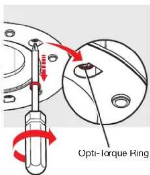
should not be used as a tightening guide due to the risk of overtightening. See the ATTENTION below.
ATTENTION:
- To avoid damaging or deforming soft ceiling material, tighten the locking arms to secure the grille adapter, but short of causing the grille adapter to deform the flat mounting surface of the ceiling.
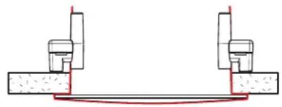
natural_image
Pure mechanical diagram showing two vertical supports connected to a horizontal beam, with no text or symbols present.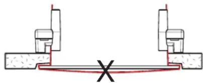
natural_image
Pure mechanical diagram showing two vertical supports connected to a horizontal beam with a central cross mark (no text or symbols)- Affix the metal grille to the magnetic grille adapter.
- Adjust the position of the subwoofer relative to the installation so that the subwoofer appears level to the critical eye and is centered over the grille. Ensure that the port tube is as close as possible to the installation surface without touching it.
NOTE: Do not allow the port tube or any part of the subwoofer to touch the installation surface. Undesired audio vibrations can occur.
Connection and Operation
Connection
NOTES:
- Pair the 8-ohm subwoofer with an amplifier that outputs up to 800 watts at 8 ohms.
- Consider the distance between the subwoofer and the amplifier and whether doubling up the speaker cable (see figure 13 on page 18) is necessary to reduce the power losses through the wires.
- Avoid audio clipping:
- Ensure that the audio source does not clip the input stage of the amplifier (check the specifications of the amplifier)
- Ensure that the audio signal does not clip the output stage of the amplifier (check the limiter or protection indicators on the amplifier).
- Apply a limiter to the amplifier channel that drives the SF 10C SUB.
- No crossover is needed when the subwoofer is used with SF 26CT, SF 3C LP, or SF 3CT LP ceiling speakers.
Configure the cable conduit access plate and captive screw connector as follows:
- Loosen the cable conduit access plate screw and remove the plate before wiring the subwoofer (see figure 11).
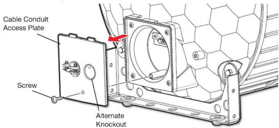
Figure 11. Removing the Cable Conduit Access Plate
-
Configure the cable conduit access plate, using either of the following methods:
-
When not using flexible conduit: Route the speaker wires through the cable clamp (see figure 12, ①).
- When using flexible conduit: Remove the cable clamp and install the flexible conduit into the plate opening. Secure the flexible conduit to the plate with the locking nut and pull the speaker wires out through the flexible conduit (2).
NOTE: The cable conduit access plate has an alternate hole that is available by removing the knockout.
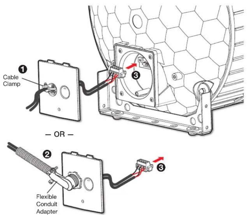
Figure 12. Connection Using a Cable Clamp or Flexible Conduit
- Strip 3/16 inch (5 mm) of the cable insulation from the wire ends.
NOTES:
- The length of exposed wires is important. The ideal length is 3/16 inch (5 mm).
- If the stripped section of wire is longer than 3/16 inch, the exposed wires may touch, causing a short circuit.
- If the stripped section of wire is shorter than 3/16 inch, wires can be easily pulled out even if tightly fastened by the captive screws.
-
Do not tin the leads before installing them in the connector. Tinned wires are not as secure in the connector and could be pulled out.
-
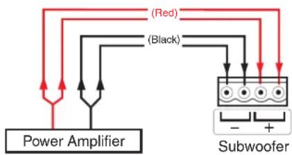
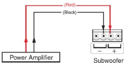
Connect four or two speaker wires to the captive screw connector, as shown by the following two methods (see figure 13).
Double Wiring
Using two 12 AWG wires yields effective 9 AWG wiring, reducing cable losses.
flowchart
graph TD
    A["Power Amplifier"] --> B["(Red)"]
    A --> C["(Black)"]
    B --> D["Subwoofer"]
    C --> D
    D --> E["-"]
    D --> F["+"]
Wire Gauge Table
| Number of Wires per Pole | Maximum Wire Gauge |
| 1 12 AWG | |
| 2 16 AWG | |
| 4 18 AWG |
Single Wiring
flowchart
graph TD
    A["Power Amplifier"] -->|Red (Black)| B["Subwoofer"]
    A -->|Red (Black)| C["Subwoofer"]
    B -->|Red (Black)| D["Subwoofer"]
Maximum Recommended Cable Length Table
| Gauge | Cable Length |
| 12 AWG doubled (effectively 9 AWG) | 253 feet (77 m) |
| 14 AWG doubled (effectively 11 AWG) | 159 feet (48 m) |
| 12 AWG single 126 feet (38 m) | |
| 16 AWG doubled (effectively 13 AWG) | 100 feet (30 m) |
| 14 AWG single 80 feet (24 m) | |
| 18 AWG doubled (effectively 15 AWG) | 63 feet (19m) |
| 16 AWG single 50 feet (15 m) | |
| 18 AWG single 32 feet (9 m) |
Figure 13. Subwoofer Wiring Methods
ATTENTION:
Operational Considerations
Play content that you are familiar with through the system and verify that it sounds as expected.
- Set the gain structure through the audio system appropriately.
- Set the gain on the subwoofer and speakers such that they are at the same sound pressure level.
- If any distortion is heard, you may be driving the subwoofer too hard and may need to add additional subwoofers to the system to get the desired sound pressure level.
Mounting a NetPA U or XPA U Amplifier to the SF 10C SUB
The included amplifier mounting kit attaches an Extron Ultra Series Power Amplifier (XPA U 2002 SB, NetPA U 2002 SB, or NetPA U 8001 SUB) to the back of an SF 10C SUB. This kit enables the amplifier to be mounted as close as possible to the subwoofer, allowing for the shortest possible speaker wiring.
Use the amplifier mounting kit to mount an Extron XPA U 2002 SB, NetPA U 2002 SB, or NetPA U 8001 SUB Power Amplifier to the SF 10C SUB as follows:
NOTE: If the SF 10C SUB is being installed into a plenum airspace, the AC input of the power amplifier must be replaced with the Flexible Conduit Adapter Kit. For detailed instructions for the installation of this adapter kit, see the user guide for the amplifier to be installed, at www.extron.com.
- On the SF 10C SUB, loosen the cable conduit access plate screw and remove the plate (see figure 14).
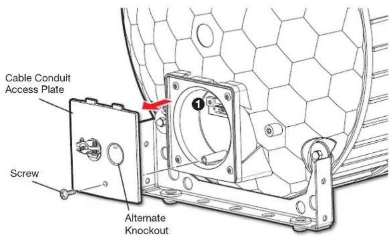
Figure 14. Removing the Cable Conduit Access Plate
-
Remove the 4-pole captive screw connector that is attached to the speaker (see figure 14, ①).
-
Feed the unterminated end of the provided short cable through the back of the cable clamp (see figure 15, ①).
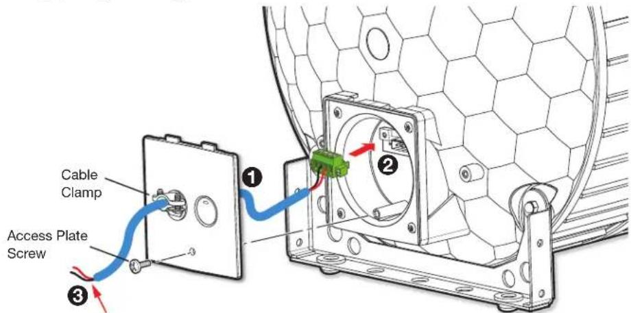
Remove the jackets from the ends of the wires and attach them to the captive screw output connector of the amplifier.
Figure 15. Feeding the Cable through the Back of the Cable Clamp
- Plug the 4-pole captive screw connector of the pre-terminated cable into the captive screw connector on the speaker (2).
- Reattach the cable conduit access plate to the speaker.
- Tighten the cable clamp.
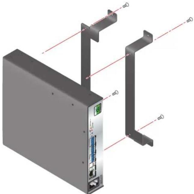
- Attach the NetPA U or XPA U amplifier to the SAK AMP SF 10C brackets using the provided screws in the holes indicated in figure 16.
Attach the amplifier with screws (4 places).
natural_image
3D diagram of an electronic device with labeled ports and connectors (no text or symbols present)Figure 16. Attaching the Amplifier to the SAK AMP SF 10C Brackets
- Attach the brackets (with the amplifier attached) to the screw holes on the end of the SF 10C SUB speaker containing the cable conduit access plate, using the provided screws (see figure 17).
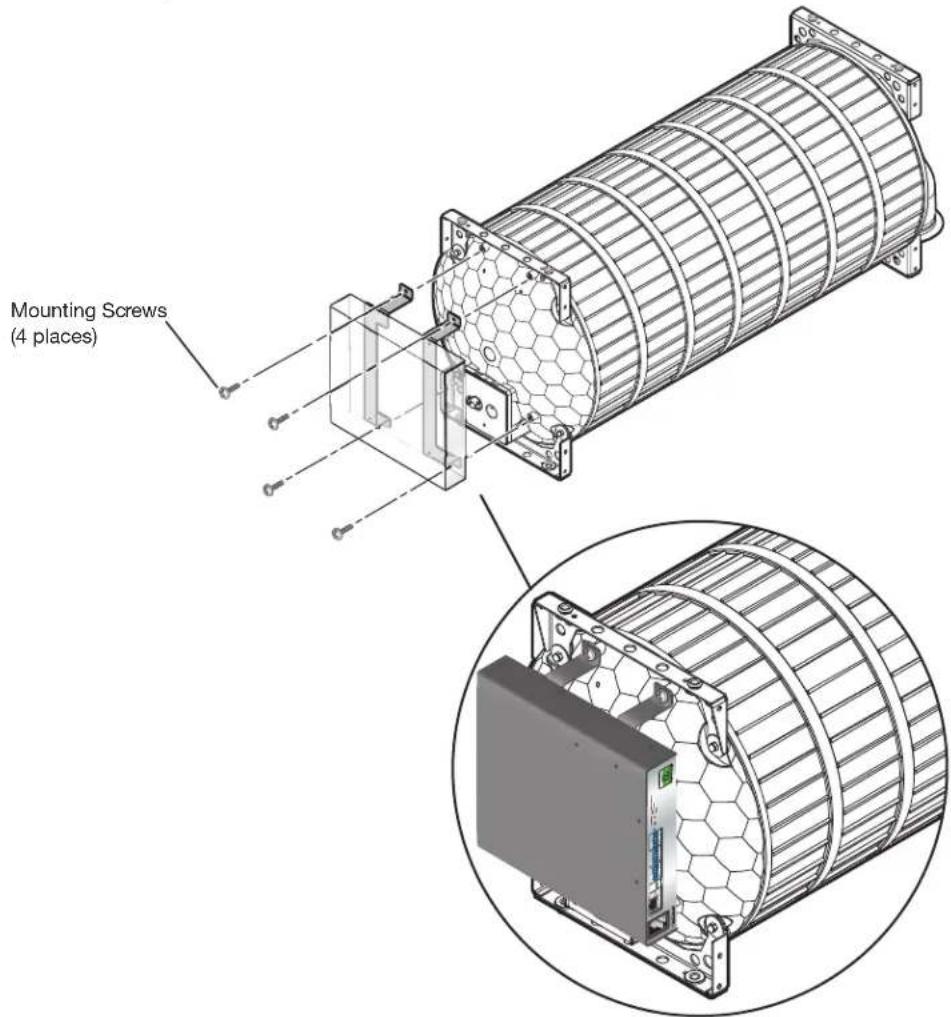
Figure 17. Attaching the Brackets and Amplifier to the SF 10C SUB Subwoofer
-
Remove the jackets from the ends of the wires on the other end of the cable (see figure 15, ③), on the previous page.
-
Wire the green captive screw connector provided with your amplifier to the unterminated ends of the cable wires (see figure 18 on the next page).
The NetPA U 8001 SUB has a 2-pole connector, while the XPA U 2002 SB and NetPA U 2002 SB have 4-pole connectors.
• NetPA U 8001 SUB:
• The red wire connects to the + pin.
- The black wire connects to the - pin.
• XPA U 2002 SB and NetPA U 2002 SB:
• The red wire connects to the Channel 1 + pin.
• The black wire connects to the Channel 2 + pin.
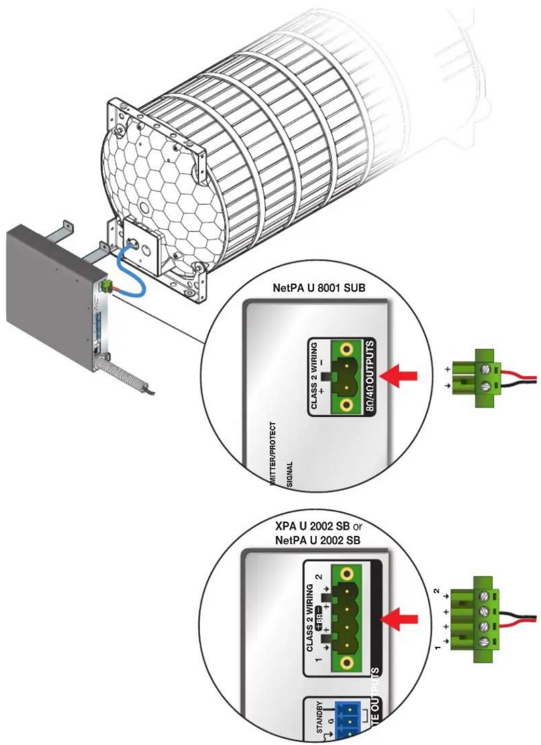
Figure 18. Connecting the Amplifier to the Subwoofer
NOTE: When using an XPA U 2002 SB or NetPA U 2002 SB with the SF 10C SUB, you must place the amplifier in bridged 8 ohm output mode (see the user guides for those amplifier models to configure the output mode).
Troubleshooting
| Symptom Description | Solution | |
| A “chuffing” sound is coming from the subwoofer. | Distortion due to port tube placement | Check the placement of the port tube. Move the tube opening slightly away from the grille surface to reduce distortion.This reduces the output level slightly, a trade-off that must be managed. |
| Distortion due to overdriven subwoofer | Attenuate the signal to the subwoofer.If the desired sound pressure level cannot be achieved at the new setting, consider relocating the subwoofer to a more favorable location (for example, edge or corner mounting — see Acoustical Reinforcement on page 5) and swapping fiberglass tiles (if used) for mineral tiles.If the desired sound pressure level still cannot be met, then the listening space requires more subwoofers. |
Extron Warranty
Extron warrants this product against defects in materials and workmanship for a period of three years from the date of purchase. In the event of malfunction during the warranty period attributable directly to faulty workmanship and/or materials, Extron will, at its option, repair or replace said products or components, to whatever extent it shall deem necessary to restore said product to proper operating condition, provided that it is returned within the warranty period, with proof of purchase and description of malfunction to:
USA, Canada, South America, and Central America:
Extron
1230 South Lewis Street
Anaheim, CA 92805
U.S.A.
Asia:
Extron Asia Pte Ltd
135 Joo Seng Road, #04-01
PM Industrial Bldg.
Singapore 368363
Singapore
Japan:
Extron Japan
Kyodo Building, 16 Ichibancho
Chiyoda-ku, Tokyo 102-0082
Japan
Europe:
Extron Europe
Hanzeboulevard 10
3825 PH Amersfoort
The Netherlands
China:
Extron China
686 Ronghua Road
Songjiang District
Shanghai 201611
China
Middle East:
Extron Middle East
Dubai Airport Free Zone
F13, PO Box 293666
United Arab Emirates, Dubai
Africa:
Extron South Africa
3rd Floor, South Tower
160 Jan Smuts Avenue
Rosebank 2196, South Africa
This Limited Warranty does not apply if the fault has been caused by misuse, improper handling care, electrical or mechanical abuse, abnormal operating conditions, or if modifications were made to the product that were not authorized by Extron.
NOTE: If a product is defective, please call Extron and ask for an Application Engineer to receive an RA (Return Authorization) number. This will begin the repair process.
USA: 714.491.1500 or 800.633.9876 Asia: 65.6383.4400
Europe: 31.33.453.4040 or 800.3987.6673
Africa: 27.11.447.6162
Japan: 81.3.3511.7655
Middle East: 971.4.299.1800
Units must be returned insured, with shipping charges prepaid. If not insured, you assume the risk of loss or damage during shipment. Returned units must include the serial number and a description of the problem, as well as the name of the person to contact in case there are any questions.
Extron makes no further warranties either expressed or implied with respect to the product and its quality, performance, merchantability, or fitness for any particular use. In no event will Extron be liable for direct, indirect, or consequential damages resulting from any defect in this product even if Extron has been advised of such damage.
Please note that laws vary from state to state and country to country, and that some provisions of this warranty may not apply to you.
- Safety Instructions
- Safety Instructions • English
- FCC Class A Notice
- VCCI-A Notice
- Conventions Used in this Guide
- Notifications
- Specifications Availability
- Extron Glossary of Terms
- Contents
- Introduction.... 1
- Installation......4
- Introduction
- About this Guide
- About the SF 10C SUB
- ATTENTION:
- Features
- Installation
- Placement Considerations and Acoustical Reinforcement
- Installation Environment
- Ceiling placement
- Placement behind a wall
- Acoustical Reinforcement
- Mounting the Subwoofer
- Suspending in the Ceiling
- WARNING:
- AVERTISSEMENT :
- Aircraft cable installation
- Remove ceiling tile and install suspension cables.
- Suspend the main subwoofer enclosure from the ceiling
- Threaded rod installation
- NOTES:
- Installing Long Legs for Vertical Installation on a Floor
- Installing Short Legs for Horizontal Installation on a Floor
- Mounting the Port Tube
- Installing the Grille
- NOTE: For installation in rigid vs. soft material:
- Connection and Operation
- Connection
- Double Wiring
- Operational Considerations
- Mounting a NetPA U or XPA U Amplifier to the SF 10C SUB
- Extron Warranty
- USA, Canada, South America, and Central America:
- Asia:
- Japan:
- Europe:
- China:
- Middle East:
- Africa:
Brand : Extron
Model : SF 10C SUB
Category : Subwoofer