KAFMWL100LA - Support pour écran plat Kogan - Free user manual and instructions
Find the device manual for free KAFMWL100LA Kogan in PDF.


| Product Type | Flat Screen Wall Mount |
| Brand | Kogan |
| Model | KAFMWL100LA |
| Compatible Screen Sizes | 26" to 55" |
| VESA Compatibility | VESA 100x100 to 400x400 mm |
| Maximum Weight Capacity | 40 kg (88 lb) |
| Material | Cold rolled steel + ABS plastic |
| Tilt Range | -15° to +5° |
| Swivel Range | None (fixed mount) |
| Level Adjustment | ±3° after installation |
| Distance from Wall | 45 mm (1.77 in) |
| Mounting Type | Wall mount, low profile |
| Installation | Professional installation recommended |
| Weight of Mount | 2.1 kg (4.6 lb) |
| Dimensions (W x H x D) | 650 x 210 x 45 mm |
| Color | Black |
| Warranty | 1 year |
| Included Accessories | Mounting hardware, screws, and manual |
| Cleaning Instructions | Wipe with dry cloth; do not use solvents |
Frequently Asked Questions - KAFMWL100LA Kogan
User questions about KAFMWL100LA Kogan
0 question about this device. Answer the ones you know or ask your own.
Ask a new question about this device
Download the instructions for your Support pour écran plat in PDF format for free! Find your manual KAFMWL100LA - Kogan and take your electronic device back in hand. On this page are published all the documents necessary for the use of your device. KAFMWL100LA by Kogan.
USER MANUAL KAFMWL100LA Kogan
natural_image
Technical line drawing of a mechanical assembly with two vertical supports and a horizontal bar, no text or symbols present.TILT EXTENDABLE FULL MOTION WALL MOUNT
(SUITABLE FOR 43-100" TVS)
KAFMWL100LA
SAFETY & WARNINGS
Read the entire user guide before you start installation and assembly. If you have any questions regarding any of the instructions or warnings, contact your local distributor for assistance.
CAUTION: Use with products heavier than the rated weights indicated may result in instability causing possible injury.
- Please closely follow the assembly instructions. Improper installation may result in damage or serious personal injury.
- Safety gear and proper tools must be used. This product should only be installed by professionals.
- This product is designed to be installed on solid concrete walls, masonry walls or wood stud walls.
- Make sure that the supporting surface will safely support the combined weight of the equipment and all attached hardware and components.
- Use the mounting screws provided and DO NOT OVER TIGHTEN mounting screws.
- This product contains small items that could be a choking hazard if swallowed. Keep these items away from children.
- This product is intended for indoor use only. Using this product outdoors could lead to product failure and personal injury.
- Never exceed the maximum load capacity of 80kg or it may result in product failure or personal injury.
IMPORTANT: Ensure that you have received all parts according to the component checklist prior to installation. If any parts are missing or faulty, contact your place of purchase for a replacement.
MAINTENANCE: Check that the product is secure and safe to use at regular intervals (at least every three months).

COMPONENTS
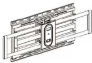
natural_image
Technical line drawing of a mechanical assembly with no visible text or symbolsA Wall mount (x1)
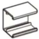
D Cable clips (x4)
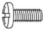
M-A M6x14
Screw (x4)
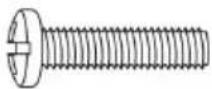
M-D M8x35 Screw (x4)
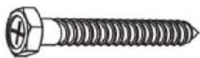
W-A ST6.3x55 Screw (x6)
natural_image
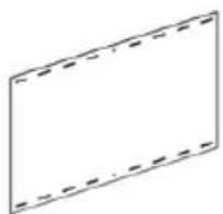
Simple geometric diagram of a rectangle with dashed lines indicating hidden edges (no text or symbols)B Template (x1)
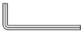
E Allen Key (4mm)
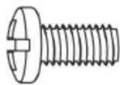
M-B M8x16
Screw (x4)
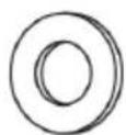
M-E D8 Washer (x4)
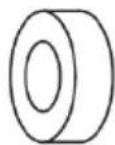
M-F Spacer (x4)
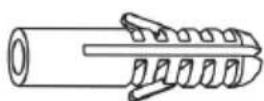
W-B Wall Anchors (x6)
natural_image
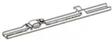
Pure technical line drawing of a mechanical component without any text, numbers, or symbolsC TV brackets (x2)
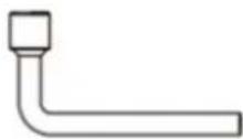
F Wrench (x1)
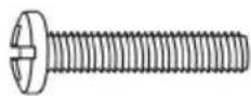
M-C M6x30
Screw (x4)
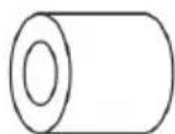
M-G Spacer (x4)
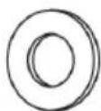
M-E D6 Washer (x4)
Tools Required
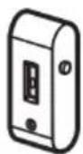
Stud finder
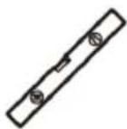
Spirit level
Pen/pencil
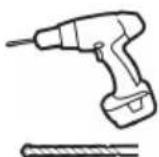
Drill & Drill
Bit
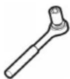
Ratchet & Sockets

Phillips head
screwdriver
ASSEMBLY
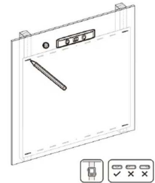
Step 1: Using a pencil and spirit level, mark the desired position for the mount on your wall, using the template (B) for the hole positions. Note: When using spirit level, ensure the bubble is centred as per the image shown below.
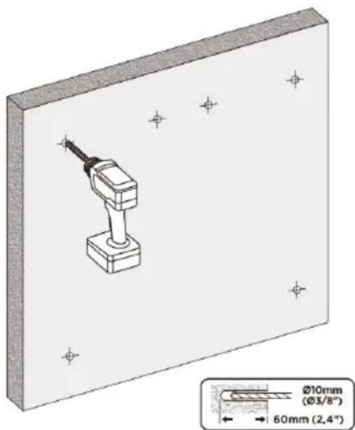
If mounting on dry wall or plaster-board, use a stud finder first to check positions of wall studs and ensure the position is free from electrical wiring. Using a drill, create the pilot holes.
Drywall / plaster: Use a 4.5mm or 3/16" drill bit, drilling 55mm deep – 4 holes
Masonry / concrete: Use a 10mm or 3 / 8'' drill bit, drilling 60mm deep - 6 holes
natural_image
Technical line drawing of a device panel with a pen and control buttons (no text or symbols)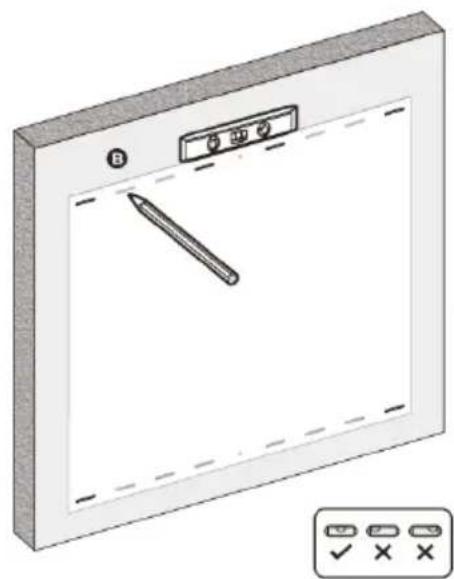
natural_image
Illustration of a blank screen with a pen and control buttons, no text or symbols present.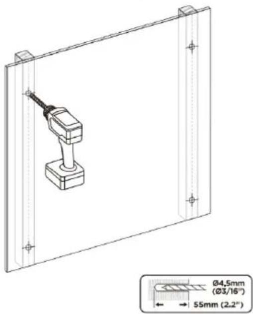
Step 2:
Drywall / plaster: Attach the wall mount (A) to the wall using the 4 ST6.3x55 screws (W-A) and D6 washers (W-C). Do not use wall anchors.
Masonry / concrete: Insert wall anchors (W-B) into all 6 drilled holes. Attach the wall mount (A) to the wall using the 6 ST6.3x55 screws (W-A) and D6 washers (W-C).
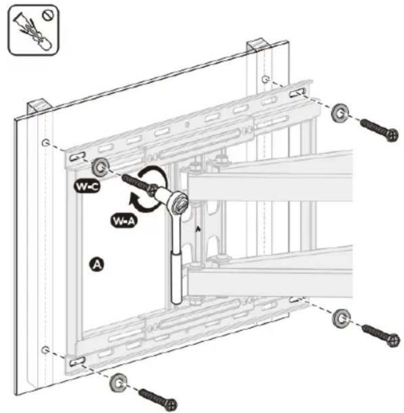
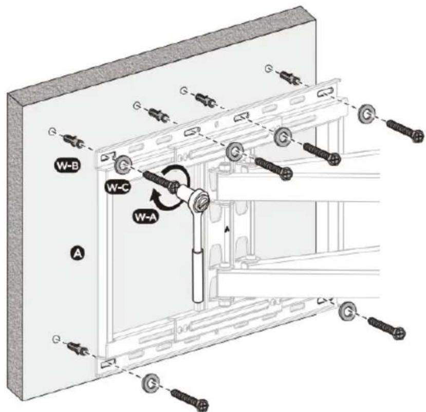
Step 3:
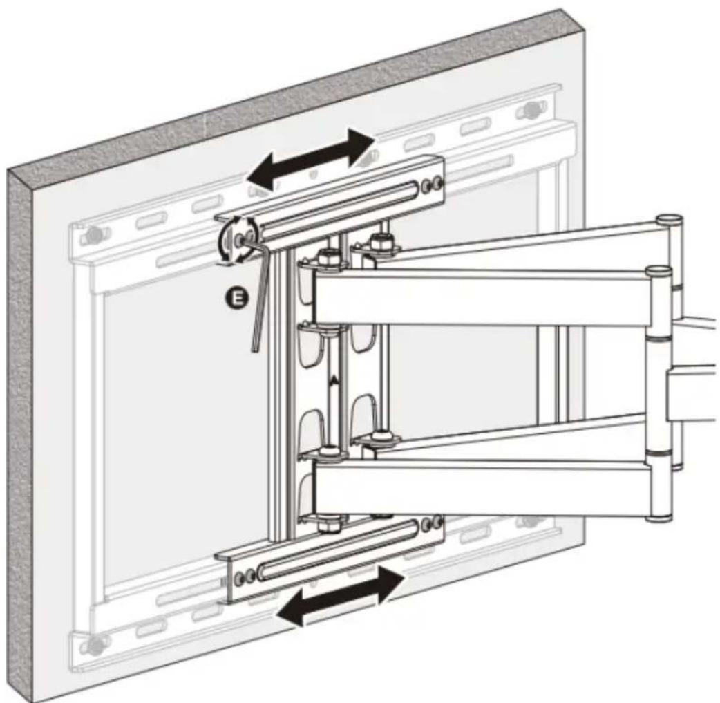
Adjust the Wall Mount (A) by loosening the fasteners with the Allen Ket. Ensure to retighten the fasteners when finished.
natural_image
Technical diagram of a mechanical assembly with labeled components and directional arrows (no text or symbols present)Step 4:
Align the TV brackets (C) with your TV's VESA holes and secure using supplied screws ("M-" set), Washer (M-E) and spacers (M-F, M-G) depending on required length.
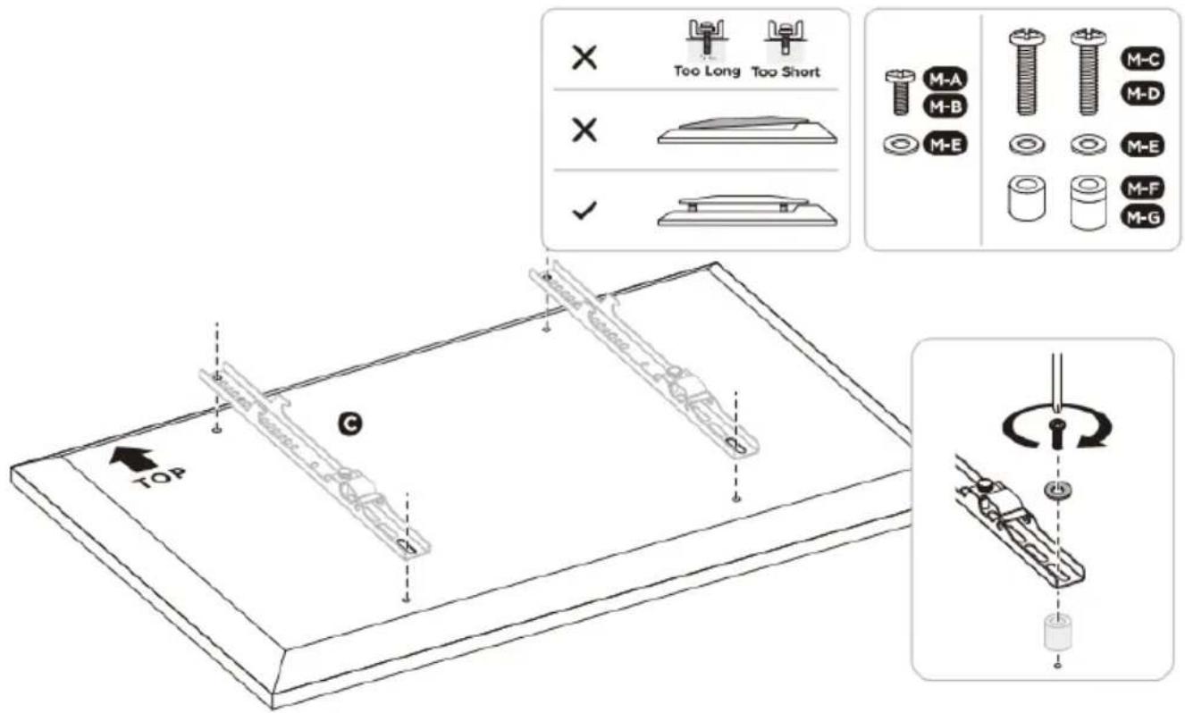
Step 5:
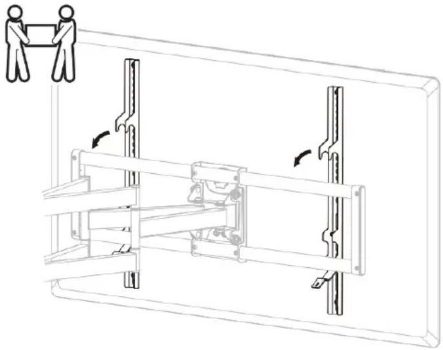
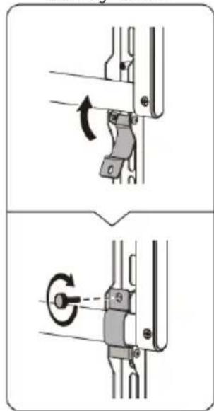
- Release the safety screws and open the safety latches.
- Hook the TV with brackets installed onto the wall mount. 2 people should carry the TV to prevent damage. Note: The TV can be mounted in 2 different positions depending on your requirements. Pay attention to ensure it is properly positioned before proceeding.
- Once in place, close the safety latches and fastens the safety screws to secure the brackets in place.
natural_image
Technical line drawing of a mechanical assembly with two human figures, showing internal components and directional arrows (no text or symbols)Safety screw
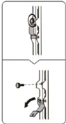
Safety latch
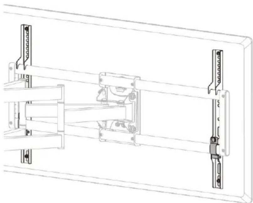
natural_image
Technical line drawing of a mechanical assembly with mounting brackets and structural components (no text or symbols)Safety latch
natural_image
Mechanical assembly diagram showing two steps of a lever mechanism (no text or labels)Safety screw
Step 6:
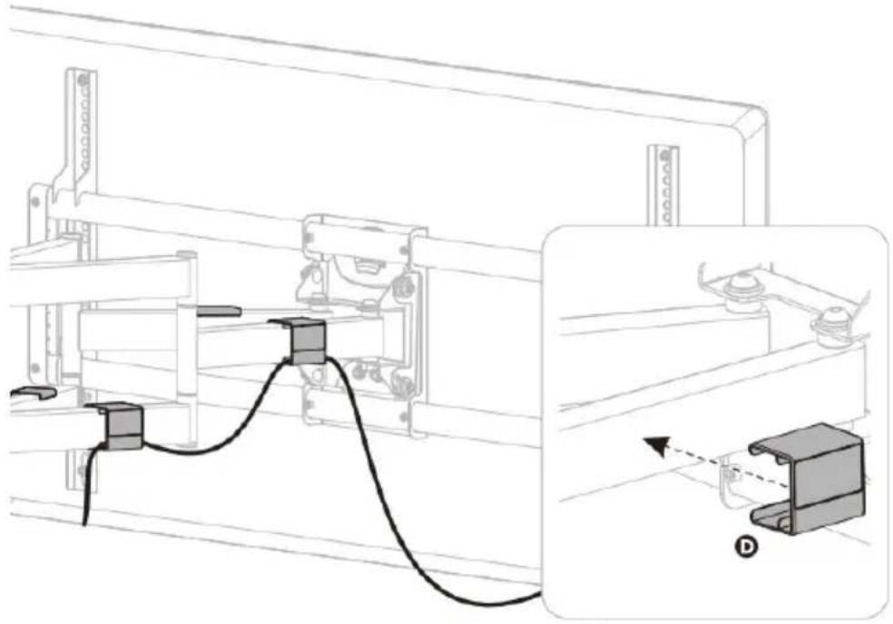
Use the supplied cable clips (D) to manage the TV cables.
natural_image
Technical line drawing of a mechanical assembly with a close-up inset showing a component labeled D (no text or symbols present)Step 7: Adjusting the Vertical Tilt
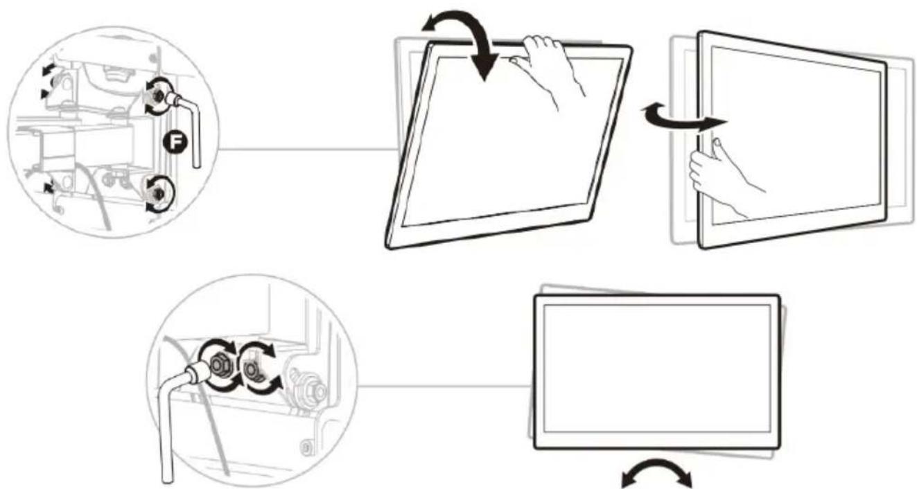
Loosen the 4 Allen screws slightly and adjust the vertical tilt of the TV.
flowchart
graph TD
    A["Device Rotation"] --> B["Assembly"]
    B --> C["Computer Display"]
    C --> D["Assembly"]
    D --> E["Computer Display"]
    style A fill:#f9f,stroke:#333
    style B fill:#ccf,stroke:#333
    style C fill:#cfc,stroke:#333
    style D fill:#fcc,stroke:#333
    style E fill:#ffc,stroke:#333
Notes:
If the display does not stop at your desired position, tighten the screws as shown.
NOTES
Need more information?
We hope that this user guide has given you the assistance needed for a simple set-up.
For the most up-to-date guide for your product, as well as any additional assistance you may require, head online to help.kogan.com
kogan.com
Brand : Kogan
Model : KAFMWL100LA
Category : Support pour écran plat