
FSB 10 Mk II - Tripod Sachtler - Free user manual and instructions
Find the device manual for free FSB 10 Mk II Sachtler in PDF.


| Product Type | Fluid Head |
| Brand | Sachtler |
| Model | FSB 10 Mk II |
| Weight | 2.7 kg (6.0 lb) |
| Height | 188 mm (7.4 in) |
| Maximum Payload | 12 kg (26.5 lb) |
| Tilt Range | +90° to -70° |
| Camera Plate Sliding Range | 120 mm (4.7 in) |
| Temperature Range | -40°C to +60°C (-40°F to +140°F) |
| Bowl Size | 100 mm |
| Battery | CR2032, 3 V (for illuminated bubble level) |
| Drag Settings (Horizontal & Vertical) | 7 settings plus 0 |
| Counterbalance Steps | 15 settings plus 0 |
| Pan Bar Type | Single pan bar (# 0992SP), length 430 mm (16.9 in) |
| Camera Fitting | Sideload camera plate (# 0164) |
| Illuminated Bubble Level | Yes, with prism and on/off switch |
| Maintenance | Clean with soft cloth; battery replacement; periodic drag operation |
| Safety Features | Safety lock on sideload; brakes; warning against overloading |
| Warranty | 1 year (extendable upon registration) |
Frequently Asked Questions - FSB 10 Mk II Sachtler
User questions about FSB 10 Mk II Sachtler
0 question about this device. Answer the ones you know or ask your own.
Ask a new question about this device
Download the instructions for your Tripod in PDF format for free! Find your manual FSB 10 Mk II - Sachtler and take your electronic device back in hand. On this page are published all the documents necessary for the use of your device. FSB 10 Mk II by Sachtler.
USER MANUAL FSB 10 Mk II Sachtler
FSB6 MkII FSB8 MkII FSB10 MkII
Part No. S2065-0001
S2069-0001
S2073-0001
EN
www.sachtler.com
Copyright © 2021
All rights reserved.
Original Instructions: English
All rights reserved throughout the world. No part of this publication may be stored in a retrieval system, transmitted, copied or reproduced in any way, including, but not limited to, photocopy, photograph, magnetic or other record without the prior agreement and permission in writing of the Vitec Group Plc.
Disclaimer
The information contained in this publication is believed to be correct at the time of printing. Vitec Production Solutions Ltd reserves the right to make changes to the information or specifications without obligation to notify any person of such revision or changes. Changes will be incorporated in new versions of the publication.
We are making every effort to ensure that our publications are updated on a regular basis to reflect changes to product specifications and features. Should this publication not contain information on the core functionality of your product, please let us know. You may be able to access the latest revision of this publication from our website.
Vitec Production Solutions Ltd reserves the right to make changes to product design and functionality without notification.
Trademarks
All product trademarks and registered trademarks are the property of The Vitec Group Plc.
All other trademarks and registered trademarks are the property of their respective companies.
Published by:
Vitec Production Solutions Ltd
Email: technical.publications@vitecgroup.com
Contents
Safety....2
Warning Symbols Used in these Instructions. . 2
Health and Safety....2
Mounting and Installation 2
Maintenance....3
About this Guide.... 4
Intended Use 4
About this User Guide 4
Warranty.... 4
Extended Warranty....4
Serial Number Location 4
Box Contents 5
Operating Elements 6
Left View....6
Operating Elements 7
Right View 7
Installation....8
PrismBubble....8
Mounting the Fluid Head 8
Mounting to a Tripod....8
Converting the Head Into a Flat Base ..... 9
Mounting / Dismounting the Camera ..... 10
Fitting the Pan Bar 12
Adjusting the Pan Bar. 12
Configuring the Pan Bar. 13
Balancing the Payload 14
Adjusting the Centre of Gravity (C of G).... 14
Additional C of G Adjustments ..... 16
Adjusting the Counterbalance 16
Adjusting the Drags 18
Transportation 19
Maintenance 20
Cleaning and Inspection. 20
Changing the Battery 20
Routine Maintenance 20
Technical Specification 21
General Notices 22
Safety
Important information on the safe installation and operation of this product. Read this information before operating the product. For your personal safety, read these instructions.
Do not operate the product if you do not understand how to use it safely.
Save these instructions for future reference.
Warning Symbols Used in these Instructions
Safety cautions are included in these instructions. These safety instructions must be followed to avoid possible personal injury and avoid possible damage to the product.

WARNING!
Where there is a risk of personal injury or injury to others, comments appear supported by the word 'WARNING'.

CAUTION!
Where there is a risk of damage to the product, associated equipment, process or surroundings, comments appear supported by the word 'CAUTION'.

Refer to the product instruction manual.

WARNING!
Pinch point, injury to fingers or hands, exercise caution.
Health and Safety
WARNING! Risk of personal injury or injury to others. All personnel must be fully trained and adhere to correct manual handling techniques and Health & Safety regulations. It is the responsibility of the local organisation to enforce safe working practices at all times.
Mounting and Installation
WARNING! Do not fit a head to a tripod that cannot support the combined mass of the head and its full payload.
WARNING! Risk of finger entrapment. Do not place fingers between the platform and the body of the fluid head.
CAUTION! Always lock the horizontal and vertical brakes when the camera is mounted but not in use or when levelling the fluid head on the tripod.
CAUTION! Hold the camera securely when mounting or dismounting from the fluid head and when making adjustments to the tripod height or footprint.
CAUTION! Always hold the pan bar when making adjustments to the counterbalance or camera position. Do not use the pan bar to lift or move the tripod and fluid head.
CAUTION! Do not attach heavy items to the pan bar.
CAUTION! Always remove the camera before transporting.
Safety
Maintenance

WARNING! The fitting of non-approved parts and or accessories or servicing by non-approved personnel could effect the safety of the product. It may also invalidate the terms and conditions of the product warranty.

CAUTION! When replacing the battery, only use the same or an equivalent type of battery recommended for use with this product.
About this Guide
Intended Use
The Sachtler FSB II fluid head range has been developed to enable smooth pan and tilt movement giving the operator total image control through a wide range of angles.
About this User Guide
This user guide has been produced to instruct the user on the correct set-up, operation and maintenance of the fluid head.
Warranty
This product is covered by a one year warranty.
The warranty will be invalidated if:
- The head is improperly installed or used in a manner contrary to this user guide.
• The head housing is opened by unauthorised personnel.
Extended Warranty
Please register at www.sachtler.com for an extended warranty period.

Box Contents
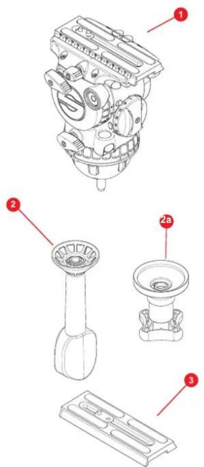

| Item | Description Part No | |
| 1 | FSB 6 II fluid head (Sideload) S2065-0001 | |
| FSB 8 II fluid head (Sideload) S2069-0001 | ||
| FSB 10 II fluid head (Sideload) S2073-0001 | ||
| 2 | Tie down 75mm 0075 | |
| 2a | Tie down 100mm S2052-1100 | |
| 3 | Sideload camera plate S 0164 | |
| 4 | Pan bar 0992SP | |
| 5 | User guide S2065-4980 |
Operating Elements
Left View

1 Vertical brake
2 Sideload system safety lock
3 Counterbalance adjustment knob
4 Illuminated Prism bubble
5 Horizontal brake
6 Vertical drag control
7 Rosette for left pan bar
8 Balance plate clamp knob
Operating Elements
Right View
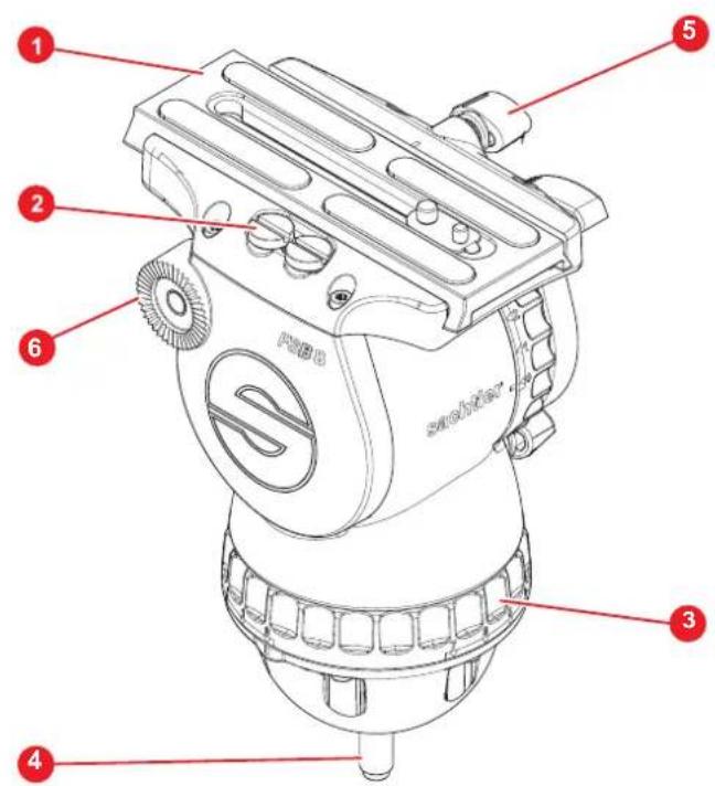
1 S Sideload camera plate S
2 Spare camera screws
3 Horizontal drag control
4 Tie down mounting
5 Balance plate clamp knob
6 Rosette for right pan bar
Installation
PrismBubble
The fluid head is fitted with an illuminating bubble level which allows easy levelling in poor lighting conditions. It also illuminates the drag controls.
The head also features a prism to view the bubble when the head is too high to view from above. This Prism also incorporates the On / Off switch.
In addition the Prism Bubble may be lit on its own or with the control LED's to enable setup up in low light conditions.
The illumination will be activated by pushing the bubble prism window.
- Pressing the window briefly will turn on the level bubble LED for approx. 10s ± 1s .
- Pressing and holding the window for >1s will turn on the level bubble LED and all control (drag) LED's for 20s ± 2s.
- Pressing the window again when any of the illuminations are on, will turn every LED off.

Mounting the Fluid Head
The fluid head is designed to be installed onto Sachtler 75 mm tripod (FSB 6, FSB 8) or 100 mm tripod (FSB 10) using the tie down.
Mounting to a Tripod
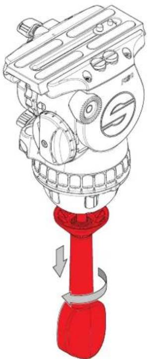
- Apply the horizontal and vertical brakes and hold the head firmly with one hand.
- Remove the tie down and place the fluid head on the tripod refitting the tie down loosely.

Installation
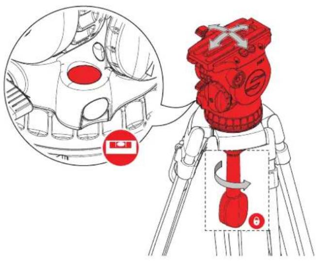
- Move the head so that the level bubble is central. Tighten the tie down, release the horizontal brake and check the level bubble remains central.
Converting the Head Into a Flat Base
- Unscrew the centre tie down stud (retain for future use) to make a flat base for a Pedestal or Slider.

Installation
Mounting and Dismounting the Camera (Sideload)
- Apply the horizontal and vertical brakes.

- Release the clamp knob.
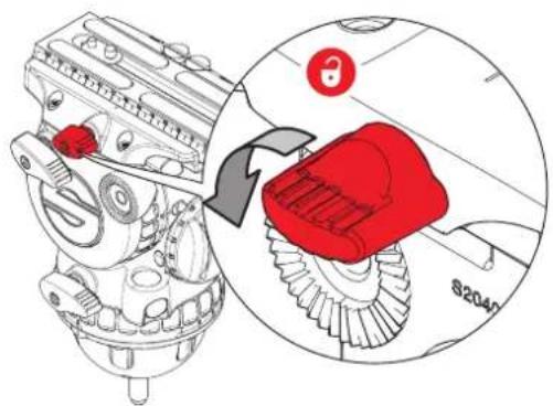
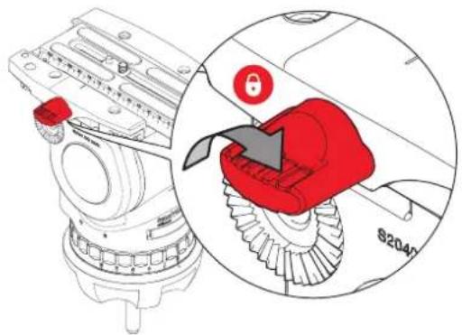
- Push the safety lock (1) and release the plate (2).

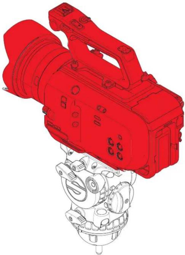
- Attach the camera plate to the camera around its centre of gravity, observe the arrow on the plate indicating the direction of the arrow. Additional screws are stored in the sliding balance plate assembly.

Installation
- Place the camera plate into the dovetail and lower into place. It will lock automatically and the lock lever will click audibly back into its initial position. Note! Camera removed for clarity

- Firmly lock the plate in position after the balance procedure using the clamp knob.
Installation
Fitting the Pan Bar
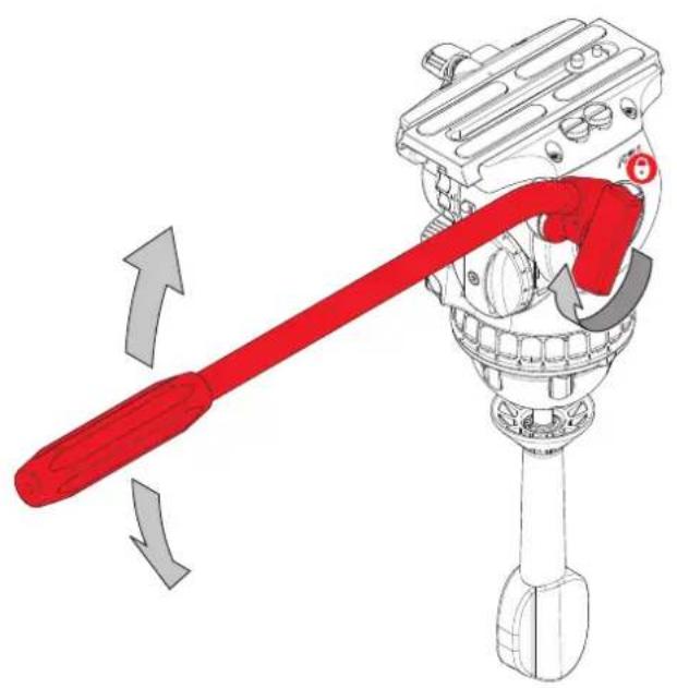
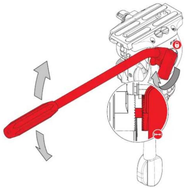
Fit and adjust the pan bar to the desired position, tighten the clamping screw ensuring the rosette teeth mesh fully.
Adjusting the Pan Bar
To adjust the position of the pan bar, loosen the clamping screw sufficiently to allow the rosettes to rotate without fowling.
Tighten the clamp when the pan bar is in the required position.
Installation
Configuring the Pan Bar
As standard, the pan bar is configured to mount on the right hand side of the fluid head. The pan bar can be configured for left hand mounting, as follows:
Installation
Balancing the Payload
Before operating the fluid head, the payload (camera, lens and any other fitted accessories) must be correctly balanced to ensure safe and reliable operation.
WARNING! When balancing the payload, it is important to be aware of the potential danger that an unbalanced payload will fall away suddenly. Maintain a firm hold on the payload until the balance is set correctly.
WARNING! Risk of finger entrapment. Do not place fingers between the platform and the body of the fluid head.
CAUTION! Always hold the pan bar when making adjustments to the counterbalance or camera position.
CAUTION! The camera, pan bars and all accessories must be fitted in their operational position before balancing the head. Any equipment fitted or adjusted later can unbalance the fluid head.
Adjusting the Centre of Gravity (C of G)
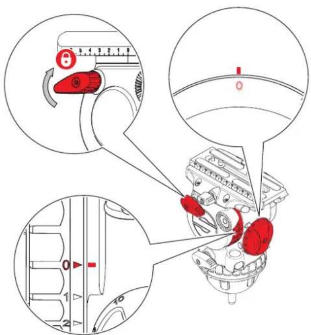
Before adjusting the counterbalance, the centre of gravity (C of G) of the payload must be centred precisely over the axis of the fluid head.

Ensure that the fluid head is level before adjusting the centre of gravity. See "Mounting the Fluid Head" on page 8.
- Apply the vertical brake and adjust the vertical setting of the fluid drag to "0". Set the counterbalance adjustment knob proportionate to the to the payload fitted.

Moving the counterbalance from one setting to another requires the head to pass the horizontal position to take affect.
Installation
Counterbalance Adjustment
- If the platform stops in a horizontal position (camera pointing directly forward) or falls away evenly in either direction, the balance is correct. Hold the pan bar firmly, disengage the vertical brake. Observe how the payload moves and where it stops.

- If the payload falls away in either direction:
(a) Unlock the sliding balance plate by unscrewing the balance plate adjuster on the balance plate.

(b) If the payload tilts backwards (points up), slide it towards the front of the fluid head. Re-lock the sliding balance plate.

(c) If the payload tilts forwards (points down), slide it towards the rear of the fluid head. Re-lock the sliding balance plate.

(d) Re-check the movement of the payload. If further adjustments are required, repeat steps 1 to 3.
Installation
Additional C of G Adjustments
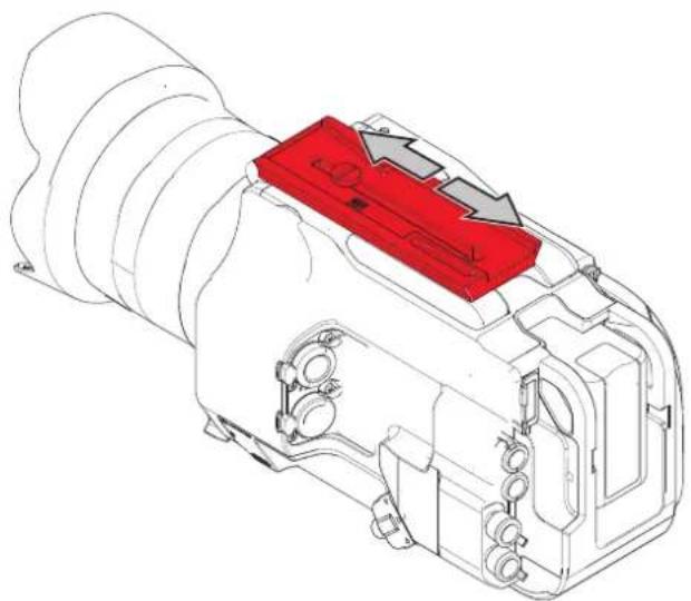
If it is not possible to correctly set the payload C of G using the standard method:
- Move the camera plate to offset the payload further in the required direction.
Adjusting the Counterbalance
The fluid head is equipped with a 15 step counterbalance adjuster to accurately balance the payload.
Note, moving the counterbalance from one setting to another requires the head to pass the horizontal position to take affect.
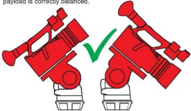
- Set the counterbalance adjustment knob to a mid-range setting.

- Tilt the payload approximately 30° in both directions and release it. If the payload stays in the same position when released, the payload is correctly balanced.
Installation
- If the payload continues to move upwards when released, the balance is set too high. Lower the counterbalance adjuster setting by one increment and retest.
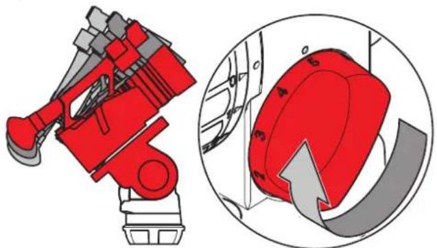
- If the payload continues to move backwards when released, the balance is set too low. Raise the counterbalance adjuster setting by one increment and retest.

- Tilt the payload through positive and negative angles of travel, checking that the payload remains at any angle of tilt unsupported.
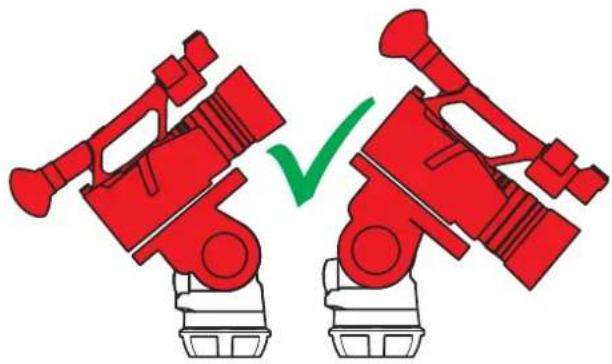

If the payload angle falls away, repeat the balancing procedure (step 3 or 4) until balance is achieved.
Installation
Adjusting the Drags
The fluid head is equipped with horizontal and vertical step drag controls. The drags help to eliminate jerks and vibrations when moving the fluid head during filming. The drags can also be fully disengaged.

CAUTIONI Always set the drag adjusters to the index positions. Setting the drag adjusters between index positions cause serious damage to the fluid head.

Applying the same drag setting to the horizontal and vertical controls enables precise and even diagonal movement.
- Turn the horizontal and vertical drag controls to the required index position (0 lowest, 7 highest drag resistance, note! FSB 6 II highest drag is 3) by aligning the arrow with the dot marker. Turn the brakes off and engage the drag by slowly panning and tilting the camera.
- Turn the drag controls to the 0 position to switch off the drag completely.

Transportation
Transportation Head Settings
To ensure smooth and reliable operation over the long life of the fluid head, the following settings should be applied to the controls during transportation or periods of storage:
| Brakes Open (OFF) | |
| Counterbalance Maximum | |
| Drags Maximum |
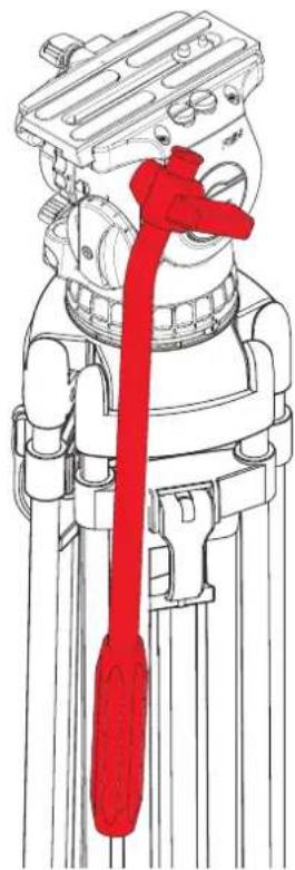
Transporting with the Pan Bar
To transport the fluid head with the pan bar attached, stow in the vertical position with the tripod legs to prevent damage.
Maintenance
Cleaning and Inspection
Clean the fluid head regularly using a soft cloth. For heavier dirt use a soft brush and a mild detergent.
Regular inspections are not required.
Changing the Battery
The illuminated bubble level is powered by one standard type button cell (CR2032, 3 V).
- Using a suitable Hex key 2.5mm, remove the Hex bolt (turn anticlockwise) from the counter balance knob.
- Remove the counter balance knob assembly to expose the battery.
- Prise the battery from its location using a finger nail or suitable flat blunt instrument. For battery disposal see "Disposal of waste batteries" on page 32
- Replace the new battery observing the correct polarity (positive face up). Press the bubble prism to check the light is working.
- Reassemble the counter balance knob. Note, the knob centrepiece must align with the notches on the head at the 12 o'clock and 6 o'clock positions.
- Replace the Hex bolt and tighten. Check the operation of the counter balance knob to confirm correct operation.

Routine Maintenance
Periodically operate the horizontal and vertical drags through their full range of indexing to ensure the engaging pins in fluid head stay lubricated.
The battery should last for approximately 2000 illumination cycles.
Technical Specification

Weight
FSB 6 II 2.5 kg (5.5 lb)
FSB 8 II 2.6 kg (5.7 lb)
FSB 10 II 2.7 kg (6.0 lb

Max. Payload
FSB 6 II 8 kg (17.6 lb)
FSB 8 II 12 kg (26.5 lb)
FSB 10 II 12 kg (26.5 lb)

Height
FSB 6 II 186 mm (7.3 in)
FSB 8 II 186 mm (7.3 in)
FSB 10 II 188 mm (7.4 in)

Drags (horizontal and vertical)
FSB 6 II 3 settings plus 0
FSB 8 II 7 settings plus 0
FSB 10 II 7 settings plus 0

Counterbalance steps
FSB 6 II 15 settings plus 0
FSB 8 II 15 settings plus 0
FSB 10 II 15 settings plus 0

Tilt range
+90° to -70°

Camera plate sliding range
120 mm (4.7 in)

Temperature range
-40°C (-40°F) to +60°C (+140°F)

Camera fitting
Sideload camera plate (# 0164)

Pan bar type
Single pan bar (# 0992SP)
Diameter 16 / 28 mm (0.63 in / 1. in)
Length 430 mm (16.9 in)

Battery
CR 2032, 3 V

Bowl size
FSB 6 II 75 mm
FSB 8 II 75 mm
FSB 10 II 100 mm
We reserve the right to make changes to the product based on technical advances.
General Notices
Declaration of Conformity
CE
Vitec Production Solutions Ltd., declares that this product has been manufactured in accordance with BS EN ISO9001.
Vitec Production Solutions Ltd., as the responsible party for regulatory compliance, declares under our sole responsibility that as delivered the described product has been assessed and determined compliant with the following:
Electromagnetic Compatibility (EMC) Directive 2014/30/EU
By application of the following harmonised standard(s):
EN55032:2015 Class A
EN55015:2013 + A1:2015
EN61547:2009
EN55035:2017
Machinery Directive 2006/42/EC
RoHS 2011/65/EU
A copy of the Declaration of Conformity is available upon request.
Environmental considerations
European Union Waste of Electrical and Electronic Equipment (WEEE) Directive (2012/19/EU)
This symbol marked on the product or its packaging indicates that this product must not be disposed of with general household waste. In some countries or European Community regions separate collection systems have been set up to handle the recycling of electrical and electronic waste products.

By ensuring this product is disposed of correctly, you will help prevent potentially negative consequences for the environment and human health. The recycling of materials helps conserve natural resources.
Visit our website for information on how to dispose of this product and its packaging.
In countries outside the EU:
Dispose of this product at a collection point for the recycling of electrical and electronic equipment according to your local government regulations.
Disposal of waste batteries
Any batteries included with this product must not be treated as household waste. By ensuring these batteries are disposed of correctly, you will help prevent potentially negative consequences for the environment and human health, and help conserve natural resources.
Read "Changing the Battery" on page 22 in this user guide for instructions on how to remove the battery from the product safely. Hand the battery over to the applicable collection point for recycling waste batteries.
Publication No. S2065-4980/0


Sachtler
A Vitec Group Brand

www.sachtler.com

- COPYRIGHT © 2021
- ORIGINAL INSTRUCTIONS: ENGLISH
- DISCLAIMER
- TRADEMARKS
- PUBLISHED BY
- CONTENTS
- SAFETY....2
- ABOUT THIS GUIDE.... 4
- BOX CONTENTS 5
- OPERATING ELEMENTS 6
- OPERATING ELEMENTS 7
- INSTALLATION....8
- MOUNTING TO A TRIPOD....8
- TRANSPORTATION 19
- MAINTENANCE 20
- TECHNICAL SPECIFICATION 21
- GENERAL NOTICES 22
- SAFETY
- WARNING SYMBOLS USED IN THESE INSTRUCTIONS
- WARNING
- CAUTION
- HEALTH AND SAFETY
- MOUNTING AND INSTALLATION
- MAINTENANCE
- ABOUT THIS GUIDE
- INTENDED USE
- ABOUT THIS USER GUIDE
- WARRANTY
- EXTENDED WARRANTY
- BOX CONTENTS
- OPERATING ELEMENTS
- INSTALLATION
- PRISMBUBBLE
- MOUNTING THE FLUID HEAD
- MOUNTING TO A TRIPOD
- CONVERTING THE HEAD INTO A FLAT BASE
- MOUNTING AND DISMOUNTING THE CAMERA (SIDELOAD)
- FITTING THE PAN BAR
- ADJUSTING THE PAN BAR
- CONFIGURING THE PAN BAR
- BALANCING THE PAYLOAD
- ADJUSTING THE CENTRE OF GRAVITY (C OF G)
- COUNTERBALANCE ADJUSTMENT
- ADDITIONAL C OF G ADJUSTMENTS
- ADJUSTING THE COUNTERBALANCE
- ADJUSTING THE DRAGS
- TRANSPORTATION
- TRANSPORTATION HEAD SETTINGS
- TRANSPORTING WITH THE PAN BAR
- CLEANING AND INSPECTION
- CHANGING THE BATTERY
- TECHNICAL SPECIFICATION
- WEIGHT
- MAX. PAYLOAD
- HEIGHT
- DRAGS (HORIZONTAL AND VERTICAL)
- COUNTERBALANCE STEPS
- TILT RANGE
- CAMERA PLATE SLIDING RANGE
- TEMPERATURE RANGE
- CAMERA FITTING
- PAN BAR TYPE
- BATTERY
- BOWL SIZE
- GENERAL NOTICES
- DECLARATION OF CONFORMITY
- CE
- ENVIRONMENTAL CONSIDERATIONS
- EUROPEAN UNION WASTE OF ELECTRICAL AND ELECTRONIC EQUIPMENT (WEEE) DIRECTIVE (2012/19/EU)
- IN COUNTRIES OUTSIDE THE EU
- DISPOSAL OF WASTE BATTERIES
Brand : Sachtler
Model : FSB 10 Mk II
Category : Tripod