
MW10 - DJ Equipment YAMAHA - Free user manual and instructions
Find the device manual for free MW10 YAMAHA in PDF.


| Product Type | DJ Mixer |
| Brand | Yamaha |
| Model | MW10 |
| Dimensions (W x H x D) | 215 x 55 x 170 mm |
| Weight | 1.2 kg |
| Power Supply | 12V DC, 500 mA |
| Input Channels | 4 (2 mono + 2 stereo) |
| Microphone Input | 1 (XLR/TRS combo) |
| Main Output | 2 x RCA |
| Headphone Output | 1 x 1/4" TRS |
| EQ | 2-band per channel (Bass, Treble) |
| Built-in Effects | None |
| Frequency Response | 20 Hz - 20 kHz |
| Signal-to-Noise Ratio | > 90 dB |
| Total Harmonic Distortion | < 0.05% |
| Phono Preamp | Yes (for turntables) |
| USB Connectivity | No |
| Software Included | None |
| Maintenance | Clean with dry cloth; avoid liquids |
| Safety | Do not expose to moisture; use only specified power adapter |
| Spare Parts Availability | Contact Yamaha support for replacement knobs, power supply |
Frequently Asked Questions - MW10 YAMAHA
User questions about MW10 YAMAHA
0 question about this device. Answer the ones you know or ask your own.
Ask a new question about this device
Download the instructions for your DJ Equipment in PDF format for free! Find your manual MW10 - YAMAHA and take your electronic device back in hand. On this page are published all the documents necessary for the use of your device. MW10 by YAMAHA.
USER MANUAL MW10 YAMAHA
natural_image
Black-and-white photo of a Yamaha USB mixing studio antenna with multiple knobs and control knobs (no visible text or labels)IMPORTANT NOTICE FOR THE UNITED KINGDOM
Connecting the Plug and Cord
IMPORTANT. The wires in this mains lead are coloured in accordance with the following code:
BLUE : NEUTRAL
BROWN : LIVE
As the colours of the wires in the mains lead of this apparatus may not correspond with the coloured makings identifying the terminals in your plug proceed as follows:
The wire which is coloured BLUE must be connected to the terminal which is marked with the letter N or coloured BLACK.
The wire which is coloured BROWN must be connected to the terminal which is marked with the letter L or coloured RED.
Making sure that neither core is connected to the earth terminal of the three pin plug.
- This applies only to products distributed by Yamaha-Kemble Music (U.K.) Ltd. (2 wires).
COMPLIANCE INFORMATION STATEMENT (DECLARATION OF CONFORMITY PROCEDURE)
Responsible Party : Yamaha Corporation of America
Address : 6600 Orangethorpe Ave., Buena Park, Calif. 90620
Telephone : 714-522-9011
Type of Equipment : USB MIXING STUDIO
Model Name : MW10
This device complies with Part 15 of the FCC Rules.
Operation is subject to the following conditions:
1) this device may not cause harmful interference, and
2) this device must accept any interference received including interference that may cause undesired operation.
See user manual instructions if interference to radio reception is suspected.
* This applies only to products distributed by YAMAHA CORPORATION OF AMERICA.
(FCC DoC)
FCC INFORMATION (U.S.A.)
- IMPORTANT NOTICE: DO NOT MODIFY THIS UNIT!
This product, when installed as indicated in the instructions contained in this manual, meets FCC requirements. Modifications not expressly approved by Yamaha may void your authority, granted by the FCC, to use the product.
-
IMPORTANT: When connecting this product to accessories and/or another product use only high quality shielded cables. Cable/s supplied with this product MUST be used. Follow all installation instructions. Failure to follow instructions could void your FCC authorization to use this product in the USA.
-
NOTE: This product has been tested and found to comply with the requirements listed in FCC Regulations, Part 15 for Class "B" digital devices. Compliance with these requirements provides a reasonable level of assurance that your use of this product in a residential environment will not result in harmful interference with other electronic devices. This equipment generates/uses radio frequencies and, if not installed and used according to the instructions found in the users manual, may cause interference harmful to the operation of other electronic devices. Compliance with FCC regulations does
not guarantee that interference will not occur in all installations. If this product is found to be the source of interference, which can be determined by turning the unit "OFF" and "ON", please try to eliminate the problem by using one of the following measures:
Relocate either this product or the device that is being affected by the interference.
Utilize power outlets that are on different branch (circuit breaker or fuse) circuits or install AC line filter/s.
In the case of radio or TV interference, relocate/reorient the antenna. If the antenna lead-in is 300 ohm ribbon lead, change the lead-in to co-axial type cable.
If these corrective measures do not produce satisfactory results, please contact the local retailer authorized to distribute this type of product. If you can not locate the appropriate retailer, please contact Yamaha Corporation of America, Electronic Service Division, 6600 Orangethorpe Ave, Buena Park, CA90620
* This applies only to products distributed by YAMAHA CORPORATION OF AMERICA. (class B)
PRECAUTIONS
PLEASE READ CAREFULLY BEFORE PROCEEDING
* Please keep this manual in a safe place for future reference.

WARNING
Always follow the basic precautions listed below to avoid the possibility of serious injury or even death from electrical shock, short-circuiting, damages, fire or other hazards. These precautions include, but are not limited to, the following:
Power supply/Power cord
- Only use the voltage specified as correct for the device. The required voltage is printed on the name plate of the device.
- Use only the specified AC power adaptor (PA-10 or an equivalent recommended by Yamaha).
- Do not place the power cord near heat sources such as heaters or radiators, and do not excessively bend or otherwise damage the cord, place heavy objects on it, or place it in a position where anyone could walk on, trip over, or roll anything over it.
Do not open
- Do not open the device or attempt to disassemble the internal parts or modify them in any way. The device contains no user-serviceable parts. If it should appear to be malfunctioning, discontinue use immediately and have it inspected by qualified Yamaha service personnel.
Water warning
- Do not expose the device to rain, use it near water or in damp or wet conditions, or place containers on it containing liquids which might spill into any openings.
- Never insert or remove an electric plug with wet hands.
If you notice any abnormality
- If the power cord or plug becomes frayed or damaged, or if there is a sudden loss of sound during use of the device, or if any unusual smells or smoke should appear to be caused by it, immediately turn off the power switch, disconnect the electric plug from the outlet, and have the device inspected by qualified Yamaha service personnel.
- If this device or the AC power adaptor should be dropped or damaged, immediately turn off the power switch, disconnect the electric plug from the outlet, and have the device inspected by qualified Yamaha service personnel.

CAUTION
Always follow the basic precautions listed below to avoid the possibility of physical injury to you or others, or damage to the device or other property. These precautions include, but are not limited to, the following:
Power supply/Power cord
- Remove the electric plug from the outlet when the device is not to be used for extended periods of time, or during electrical storms.
- When removing the electric plug from the device or an outlet, always hold the plug itself and not the cord. Pulling by the cord can damage it.
- To avoid generating unwanted noise, make sure there is 50 cm or more between the AC power adaptor and the device.
- Do not cover or wrap the AC power adaptor with a cloth or blanket.
Location
- Before moving the device, remove all connected cables.
- A void setting all equalizer controls and faders to their maximum. Depending on the condition of the connected devices, doing so may cause feedback and may damage the speakers.
- Do not expose the device to excessive dust or vibrations, or extreme cold or heat (such as in direct sunlight, near a heater, or in a car during the day) to prevent the possibility of panel disfiguration or damage to the internal components.
- Do not place the device in an unstable position where it might accidentally fall over.
- Do not use the device in the vicinity of a TV, radio, stereo equipment, mobile phone, or other electric devices. Doing so may result in noise, both in the device itself and in the TV or radio next to it.
Connections
- Before connecting the device to other devices, turn off the power for all devices. Before turning the power on or off for all devices, set all volume levels to minimum.
Handling caution
- Do not insert your fingers or hands in any gaps or openings on the device.
- A void inserting or dropping foreign objects (paper, plastic, metal, etc.) into any gaps or openings on the device. If this happens, turn off the power immediately and unplug the power cord from the AC outlet. Then have the device inspected by qualified Yamaha service personnel.
- Do not use the device or headphones for a long period of time at a high or uncomfortable volume level, since this can cause permanent hearing loss. If you experience any hearing loss or ringing in the ears, consult a physician.
- Do not rest your weight on the device or place heavy objects on it, and avoid use excessive force on the buttons, switches or connectors.
XLR-type connectors are wired as follows (IEC60268 standard): pin 1: ground, pin 2: hot (+), and pin 3: cold (-).
Insert TRS phone jacks are wired as follows: sleeve: ground, tip: send, and ring: return.
Yamaha cannot be held responsible for damage caused by improper use or modifications to device, or data that is lost or destroyed.
Always turn the power off when the device is not in use.
Even when the power switch is in the "STANDBY" position, electricity is still flowing to the device at the minimum level. When you are not using the device for a long time, make sure you unplug the power cord from the wall AC outlet.
The performance of components with moving contacts, such as switches, volume controls, and connectors, deteriorates over time. Consult qualified Yamaha service personnel about replacing defective components.
SPECIAL NOTICES
- This owner's manual is the exclusive copyrights of Yamaha Corporation.
- The supplied software is the exclusive copyrights of Steinberg Media Technologies GmbH.
- Use of the supplied software and this manual is governed by the license agreement which the purchaser fully agrees to upon breaking the seal of the software packaging. (Please read carefully the Software Licensing Agreement at the end of this manual before installing the application.)
- Copying of the supplied software or reproduction of this manual in whole or in part by any means is expressly forbidden without the written consent of the manufacturer.
- Yamaha makes no representations or warranties with regard to the use of the software and documentation and cannot be held responsible for the results of the use of this manual and the software.
- The supplied disk is a CD-ROM. Do not attempt to play the disk on an audio CD player. Doing so may result in irreparable damage to your audio CD player.
- Visit the web address below for the latest information on supplied software and operating system requirements. http://www.yamahasynth.com/
- The screen displays as illustrated in this owner's manual are for instructional purposes, and may appear somewhat different from the screens which appear on your computer.
- The illustrations as shown in this owner's manual are for instructional purposes only, and may appear somewhat different from those on your device.
This product incorporates and bundles computer programs and contents in which Yamaha owns copyrights or with respect to which it has license to use others' copyrights. Such copyrighted materials include, without limitation, all computer software, style files, MIDI files, WAVE data, musical scores and sound recordings. Any unauthorized use of such programs and contents outside of personal use is not permitted under relevant laws. Any violation of copyright has legal consequences. DON'T MAKE, DISTRIBUTE OR USE ILLEGAL COPIES.
This device is capable of using various types/formats of music data by optimizing them to the proper format music data for use with the device in advance. As a result, this device may not play them back precisely as their producers or composers originally intended.
- Windows is the registered trademarks of Microsoft® Corporation.
- Apple and Macintosh are trademarks of Apple Computer, Inc., registered in the U.S. and other countries.
• Steinberg and Cubase are the registered trademarks of Steinberg Media Technologies GmbH. - The company names and product names in this Owner's Manual are the trademarks or registered trademarks of their respective companies.
Specifications and descriptions in this owner's manual are for information purposes only. Yamaha Corp. reserves the right to change or modify products or specifications at any time without prior notice. Since specifications, equipment or options may not be the same in every locale, please check with your Yamaha dealer.
Foreword
Thank you for choosing a Yamaha MW10 USB Mixing Studio. The MW10 includes an audio mixer equipped with a USB interface for digital audio data transfer, and Cubase LE DAW (Digital Audio Workstation) software for Windows® and Macintosh® computer operating systems. With the MW10 USB Mixing Studio and your personal computer you have the basic elements of a high-performance computer recording system that is easy to set up and operate.
In order to take full advantage of the many features and capabilities provided by the MW10, we urge you to read this owner's manual thoroughly before using your MW10 system, and keep the manual in a safe, accessible location for future reference.
Features
Connect To Your Computer via a Single USB Cable (page 7)
The MW10 mixer connects to your computer via the supplied USB cable. Stereo audio data is transferred in both directions—from the mixer to the computer, and vice-versa—via the USB connection (44.1 kHz or 48 kHz sampling frequency).
No Driver Installation Required (page 7)
The MW10 system uses the standard drivers included in your computer's operating system, so there's no need to install any extra driver software.
Cubase LE DAW Software Supplied (page 7)
Cubase LE software, included in the MW10 package, offers versatile, high-performance hard-disk recording capability.
3-Band EQ On Each Channel (page 15)
Each channel of the MW10 mixer features full 3-band equalization, providing broad, musical response-shaping capability.
Mixer Functions (page 15)
With up to four mic/line inputs or up to four stereo inputs, the MW10 can simultaneously connect to a wide range of devices: microphones, line-level devices, stereo synthesizers, and more. For example, you can connect two microphones and four stereo devices, or four microphones and two stereo devices.
48V Phantom Power (page 16)
A PHANTOM switch supplies +48V phantom power to the mixer's microphone inputs, so you can use high-quality phantom-powered condenser microphones for superior recording quality.
Contents
Foreword 5
Features 5
Contents 5
Before Turning on the Mixer 6
Turning the Power On/OFF 6
Computer System Requirements 6
Cubase LE System Requirements 6
Quick Guide 7
-
Installing Cubase LE 7
-
Connections 7
-
Powering Up the System 8
-
Adjusting Level and Equalization 9
-
Recording with Cubase LE 10
-
Mixing with Cubase LE 13
Front & Rear Panels 15
Channel Control Section 15
Master Control Section 16
Input/Output Section 17
Rear Section 19
Setting Up 20
Setup Procedure 20
Setup Examples 20
Troubleshooting 21
Appendix 23
Specifications 23
Dimensional Diagrams 25
Block Diagram and Level Diagram 26
SOFTWARE LICENSE AGREEMENT ..... 27
Before Turning on the Mixer
1 Be sure that the mixer's power switch is in the STANDBY position.

Use only the PA-10 adaptor included with this mixer. Use of a different adaptor may result in equipment damage, overheating, or fire.
2 Connect the power adaptor to the AC ADAPTOR IN connector (1) on the rear of the mixer, and then turn the fastening ring clockwise (2) to secure the connection.
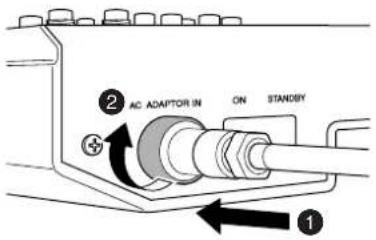
3 Plug the power adaptor into a standard household power outlet.

- Be sure to unplug the adaptor from the outlet when not using the mixer, or when there are lightning storms in the area.
- To avoid generating unwanted noise, make sure there is 50 cm or more between the power adaptor and the mixer.
Turning the Power On/OFF
Press the mixer's power switch to the ON position. When you are ready to turn the power off, press the power switch to the STANDBY position.

Note that trace current continues to flow while the switch is in the STANDBY position. If you do not plan to use the mixer again for a long while, please be sure to unplug the adaptor from the wall outlet.
NOTE
To prevent loud pops and noises, turn on the power to your sound gear starting with the sources (instruments, CD players, etc.) and ending with the power amplifier or powered speakers.
Example: Instruments, microphones, and CD players first, then the mixer, and finally the power amplifier or powered speakers.
When turning off the power to the system, reverse the order described above.
Computer System Requirements
Windows
| Computer Windows-based computer with built-in USB interface | |
| OS Windows | XP |
| CPU 750MHz or higher Intel Pentium/Celeron processor | |
| Memory More than 96MB (128MB or more recommended) | |
Macintosh
| Computer Macintosh computer with built-in USB interface |
| OS MacOS X 10.3.3 or higher |
| CPU Macintosh G3 processor 300MHz or higher |
| Memory More than 128MB |
Cubase LE System Requirements
Windows
| OS Windows | XP |
| CPU 500 MHz or higher Pentium III or AMD K7(1GHz or more recommended Pentium III/Athlon) | |
| Memory | More than 256MB (512MB or more recommended) |
| Hard Disk 1GB or more | |
Macintosh
| OS MacOS X 10.3.3 or higher | |
| CPU Macintosh G4 processor 450MHz or higher | |
| Memory | More than 256MB (512MB or more recommended) |
| Hard Disk 1GB or more | |
Quick Guide
This quick setup and operation guide covers everything from installing the Cubase LE software to using Cubase LE for recording and mixdown. While going through this section you might find it useful to also refer to the "Front and Rear Panels" section on page 15, as well as the pdf manual supplied with the Cubase LE software.
Step
1 Installing Cubase LE
1 Turn the computer on.
2 Insert the supplied CD-ROM into the computer's CD-ROM drive.
3 Follow the on-screen instructions to install the Cubase LE software.
The serial number is printed on the sheet located inside the CD-ROM envelope.
NOTE • Please install Cubase LE while connected to the internet.
- Please enter all required items during installation.
- For Macintosh computers double-click the "Cubase LE.pkg" icon.
Step
2 Connections
1 Connect the MW10 to the Computer.
Connect the MW10 mixer to your computer using the supplied USB cable.
USB Connection Precautions
Be sure to observe the following points when connecting to the computer's USB interface. Failure to observe these rules can result in computer freezes/hang-ups and possibly data loss or corruption.
If the computer or MW10 does stop operating properly, turn the power off and then on again, and restart the computer.

- Be sure to wake the computer from sleep/suspended/standby mode before making a connection to the computer's USB connector.
- Connect the MW10 to the computer before turning the MW10 power on.
- Always quit all applications running on the computer before turning the MW10 power on or off, or connecting or disconnecting the USB cable.
- Wait at least 6 seconds between turning the MW10 on or off, and between connecting or disconnecting the USB cable.

When connecting or disconnecting the USB cable be sure to turn the 2TR IN/USB control all the way down.
NOTE
Disconnect the USB cable before you use the computer without the MW10.
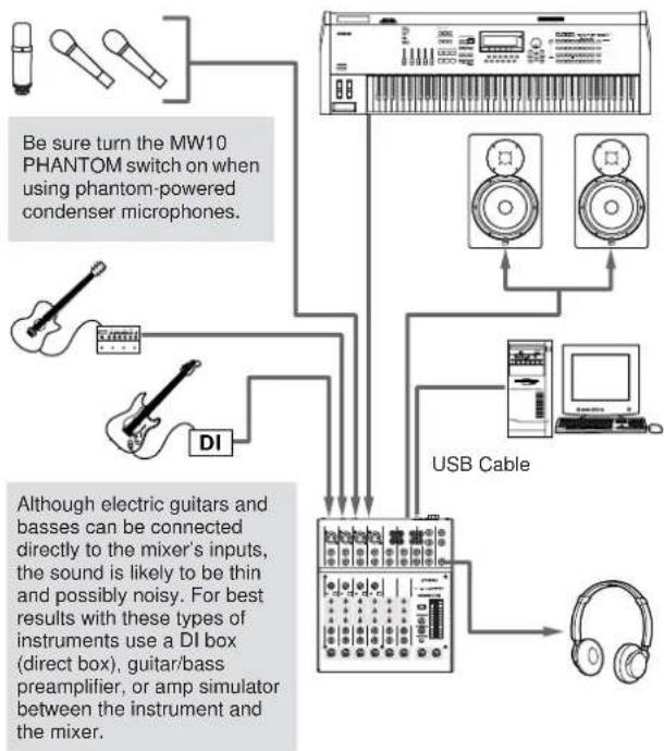
2 Connecting Microphones and/or Instruments.
For details on making connections refer to the "Input/Output" section on page 17, and the "Setting up" section on page 20.
flowchart
graph TD
    A["Instrument 1"] --> B["Device with keyboard"]
    C["Instrument 2"] --> B
    D["Instrument 3"] --> B
    E["Instrument 4"] --> B
    F["Instrument 5"] --> B
    G["Instrument 6"] --> B
    H["Instrument 7"] --> B
    I["Instrument 8"] --> B
    J["Instrument 9"] --> B
    K["Instrument 10"] --> B
    L["Device 1"] --> M["USB Cable"]
    N["Device 2"] --> M
    O["Device 3"] --> M
    P["Device 4"] --> M
    Q["Device 5"] --> M
    R["Device 6"] --> M
    S["Device 7"] --> M
    T["Device 8"] --> M
    U["Device 9"] --> M
    V["Device 10"] --> M
Balanced Cables and Unbalanced Cables
Two types of cables can be used to connect microphones, electronic instruments, and other audio sources to the mixer's inputs, as well as to connect the mixer's outputs to a power amplifier or related gear: balanced or unbalanced. Balanced cables are highly resistant to noise, and are the best choice for low-level signals such as the output from microphones, as well as for long cable runs. Unbalanced cables are generally used for short runs from line-level sources such as synthesizers.
Cable Guidelines
Microphone cable: Balanced is best.
Short line-level cables: Unbalanced cable is fine in a relatively noise-free environment.
Long line-level cables: Balanced is best.
Connector Types
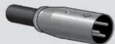
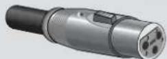
XLR Connectors
This 3-pin connector is resistant to externally induced noise, and is used primarily for balanced connections. With properly designed receiving circuitry cables with this type of connector can also be used for unbalanced signals. XLR type connectors are the standard for microphone connections as well as most professional audio gear.
Phone Connectors
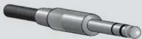
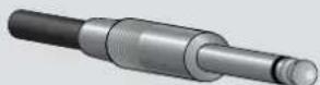
Phone connectors are available in mono and stereo versions. Stereo types are also known as "TRS" connectors (Tip-Ring-Sleeve), and are
used for stereo headphone jacks, insert jacks, and also to carry balanced signals in many cases. Unbalanced types are used for mono signals — guitar cables are a common example.
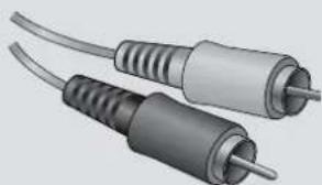
RCA Pin Connectors
This type of unbalanced connector is most commonly found on home audio and video equipment. RCA type pin jacks are often color coded: white for left audio channel and red for right audio channel, for example.
natural_image
Two metallic audio/video cables with leads, shown from different angles (no text or symbols visible)Step
3 Powering Up the System
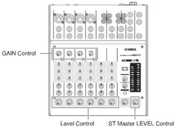
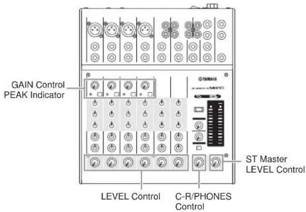
1 Turn the power to all gear that is to be connected to the MW10 off/standby (except the computer), and set the ST Master Level Control, Channel LEVEL Controls, and GAIN Controls to their minimum settings.
2 To prevent loud pops and noises, turn on the power to your sound gear starting with the sources (instruments, CD players, etc.) and ending with the power amplifier or powered speakers.
Example: Instruments, microphones, and CD players first, then the mixer, and finally the power amplifier or powered speakers.

Observe the following precautions when turning on phantom power.
- Make sure that the PHANTOM switch is off when phantom power is not needed.
- Make sure that no equipment other than phantom-powered microphones is connected to the XLR type inputs when turning phantom power on. Applying phantom power to equipment other than phantom-powered microphones can damage the equipment. The exception to this rule is balanced dynamic microphones, which can safely be left connected while phantom power is applied to the XLR Inputs.
- To minimize the possibility of speaker damage, turn phantom power on ONLY while your power amplifier or powered speakers are switched off. It's also a good idea to turn the mixers output controls—the ST Master LEVEL Control and Channel LEVEL Controls—all the way down when turning phantom power on.
NOTE
The first time you connect to the computer's USB connector, or change the connection to a different USB port, a driver installation display may appear. If this occurs, wait until the installation is complete before proceeding.
Step
4 Adjusting Level and Equalization
Level Adjustment
1 The first step in adjusting levels is to set the level controls on all instruments and other sources appropriately.
2 Adjust the channel GAIN controls so that the corresponding peak indicators flash briefly on the highest peak levels (GAIN controls are not provided on the stereo channels—7/8 and 9/10).
3 Raise the ST Master LEVEL Control to the “◀” position.
4 Adjust the Channel LEVEL Controls to create the desired initial balance while monitoring via headphones or monitor speakers. The overall headphone level is adjusted by the C-R/PHONES control.
EQ Adjustment
The MW10 mixer's 3-band equalizers with independent HIGH, MID, and LOW bands make it easy to shape the tone of independent channels to achieve the best possible mix.
Use the High-pass Filter for Microphone Input
As the name implies, a "high-pass filter" allows only signals above a certain frequency to pass. Conversely, signals below that "cutoff frequency" are attenuated. When an MW10 high-pass filter is turned on, signals below 80 Hz are attenuated. This can be useful for minimizing low-frequency breath noise from a vocalist, as well as handling noise, or rumble transmitted via the microphone stand. It is generally a good idea to turn the high-pass filter on for microphone channels.
Equalizer Tips
The best advice that can be given regarding equalization while recording is simply to use as little equalization as possible. If you want a little more presence you can turn the HIGH end up a bit. Or you can boost the bass a little if you feel the low end is lacking. During recording it's better to use EQ sparingly for compensation only.
Step
5 Recording with Cubase LE
This section describes the procedure for recording via the MW10 mixer to the Cubase LE software we installed earlier.
5 NOTE For details on operation of the Cubase LE software refer to the pdf-format manual provided with the software.
Cubase LE Setup
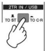
1 To prevent the playback sound from Cubase LE from being directly re-recorded, press the MW10 2TR IN/USB (ST/TO C-R) switch so that it's in the on (TO C-R) position.
With the setting the playback sound can be monitored via the C-R OUT connectors as well as the PHONES jack.
2 Launch Cubase LE.
Windows:
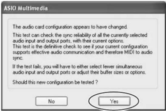
Click [Start] → [All Programs] → [Steinberg Cubase LE] → [Cubase LE] to launch the program. If the ASIO Multimedia dialog window appears, click [Yes].
Macintosh:
Double click the [Cubase LE] icon in your "Applications" folder, or single-click the [Cubase LE] icon in the dock if it has been placed there.
5 NOTE • If you specified a file destination when installing the Cubase LE software, launch the application from that location.
- Create a Cubase LE shortcut or Alias on your desktop so you can easily launch the program when required.
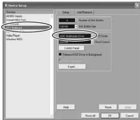
3 Select [Device Setup] from the [Devices] menu to open the Device Setup window.
Windows:
Select [VST Multitrack] in the [Devices] field on the left side of the window. Select [ASIO Multimedia Driver] in the [ASIO Driver] field on the right side of the window, and click [Apply] or [OK].
Macintosh:
Select [VST Multitrack] in the [Device] field on the left side of the window. Select [USB Audio CODEC (2)] in the [ASIO Driver] field on the right side of the window, and click [OK]. Skip ahead to step 7, below.
NOTE
Under Mac OS X you can select either [USB Audio CODEC (1)] or [USB Audio CODEC (2)] in the [ASIO Driver] driver field. Normally you should select or [USB Audio CODEC (2)], but if you will only be playing back and mixing previously recorded data you can select [USB Audio CODEC (1)] to lighten the load on the computer's CPU.
4 On a Windows computer click [Control Panel] in the Device Setup window. The ASIO Multimedia Setup dialog window will appear. Click [Advanced Options].
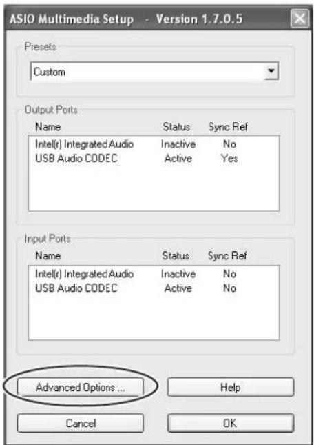
5 The ASIO Multimedia Setup – Advanced Options window will appear. Check only the input port and output port [USB Audio CODEC] checkbox.
![ASIO Multimedia Setup - Advanced Options Sample Rate: 44100 Hz Buffer sizes (in the list below) are set separately for each sample rate selected here. Output Ports Device Name Audio Buffer Size [Samples] Offset [Samples] Audio Channels Bits per Sample Sync Reference USB Audio CODEC 5 5912 0 2 16 No 5 5912 0 2 16 Yes Input Ports Device Name Audio Buffer Size [Samples] Offset [Samples] Audio Channels Bits per Sample Sync Reference USB Audio CODEC 5 5912 0 2 16 No USB Audio CODEC 5 5912 0 2 16 Yes Selected Port Check Buffers and Sync... Direct Buffer Size... Run Simulation... Presets Custom Save Delete Port Order Move up Move down Global Settings Sync Reference Sample Position - Output Card Options Help Cancel OK](/content/2026/05/906782/images/47bddc661febfd003b87514b88c5f6fac0177dc6b1b60e620b6af028c831413f.jpg)
6 Click [OK] in the ASIO Multimedia Setup – Advanced Options, ASIO Multimedia Setup, and Device Setup dialog windows to close the windows.
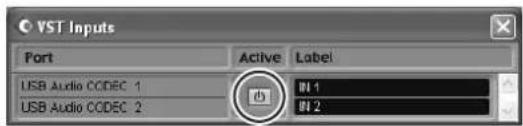
7 Select [VST Inputs] in the [Devices] menu. The VST Inputs window will open. Engage the Port [USB Audio CODEC] Active button (☐) and close the VST Inputs window.
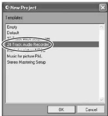
8 Select [New project] from the [File] menu to create a new project file.
The New Project dialog window will open. For this example select [24 Track Audio Recorder] and click [OK].
5 NOTE Recorded Cubase LE data is stored as a "project file" for each song.
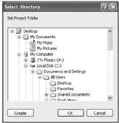
9 When the directory selection dialog window appears, select the folder to which the project and audio files for the project are to be stored, and click [OK].
An empty 24-audio-track project window will appear.
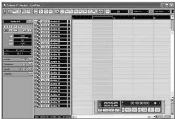
Preparing to Record
1 Click in the track list (the area in which the track names are displayed) to select a track to record on.
For this example select [Audio 01]. The various settings for the selected track are available in the Inspector on the left side of the display.
NOTE If the Inspector is not showing, click the [Show Inspector] button (in the upper left area of the project window.
![[Show Inspector] button [Stereo Switch] button Audio 01 Audio 02 Audio 03 Audio 04 Audio 05 Audio 06 Audio 07 Audio 08 Audio 09 Audio 10 n : IN1-IN2 out : BUS 1 Inspector](/content/2026/05/906782/images/77251b14949c40be45191623b0f5b9e0f35b9beb5cee05869f55ecf6a5b993de.jpg)
2 Use the [Stereo Switch] buttons in the Inspector to select stereo or monaural operation for the track: (☐) for stereo operation and (☐) for monaural.
For the example select the stereo mode. You will normally use a monaural track when recording vocals or guitar, and a stereo track when recording synthesizers with stereo outputs, for example. You might want to use a stereo track to record a guitar processed through a preamplifier or amp simulator with stereo outputs.
3 Select [Mixer] from the [Devices] menu to open the mixer window.
Click the arrow in the upper left corner of the mixer window and select [Wide] to increase the width of the mixer's channel strips. Leave the mixer window open until you have finished recording for easy access.
![[Record Enable] button Channel strip](/content/2026/05/906782/images/6a5d8a14eef2071547f1e8107788016477871ab0409ce03a58dff2a605c4065f.jpg)
4 Make sure that the [Record Enable] button (●) on the left side of the channel strip on.
If the [Record Enable] button is off (click it to turn it on. The input signal level will be displayed on the channel strip level meter while the [Record Enable] button is on.
5 Play the instrument to be recorded and, while watching the mixer window level meter, adjust the MW10 GAIN controls, Channel LEVEL Controls, and ST Master LEVEL Control so that the meter never goes above 0.0 dB.
NOTE The Cubase LE channel strip fader only affects the playback output level from Cubase LE.
The maximum level encountered is displayed numerically in the peak level display at the top of the channel strip.
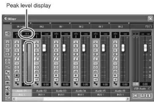
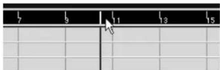
6 Specify the point at which you want to start recording via the ruler at the top of the project window.
Click the black area of the ruler to move the project cursor (the vertical black line) to that position.
7 Open the [Transport] menu and turn [Start Record at Left Locator] off.
isRecording and Playback
1 Click the Transport panel [Record] button to begin recording.
When recording is started the project cursor will begin moving to the right and a box that displays the recording results will be created.
Transport panel
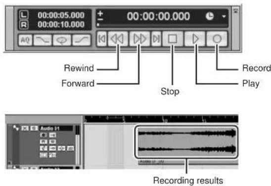
2 Play the part.
3 When you have finished recording the track, click the Transport panel [Stop] button.
4 To hear playback of the track you have just recorded, use either the Transport panel [Rewind] button or the ruler to rewind to the beginning of the recorded section, then click the Transport panel [Play] button.
The playback level will be displayed via the master section level meter on the right side of the Mixer window. The channel strip level meters will become active when you turn the channel strip [Record Enable] button off.
5 NOTE When a pair of headphones are plugged into the MW10 PHONES jack, you can adjust the headphone listening level via the MW10 C-R/PHONES control and the 2TR IN/USB control.
5 To save the project file select [Save] from the [File] menu and enter a file name before actually saving the file.
Save your project frequently to insure against losing large amounts of data if a problem occurs.
6 Repeat steps 1 through 5 to record further material on the same track.
7 To record additional material on a different track, select a new track and repeat the same record procedure.
Step
6 Mixing with Cubase LE
In this section we'll try mixing down multiple recorded audio tracks to stereo, and creating a wave file. Mixes can be stored as WAV or AIFF files, which can then be recorded to audio CDs.
1 Launch Cubase LE and open a project file.
2 Select [Mixer] from the [Devices] menu to open the mixer window.
3 Turn the [Record Enable] buttons for all recorded tracks off in order to display the corresponding levels via the channel-strip levels meters.
4 Click the Transport panel [Play] button.
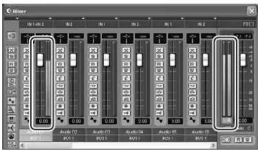
5 Drag the channel strip faders up and down while listening to playback to adjust the mix as required.
The master gain fader on the right side of the window can also be used to adjust the overall level.
Start with the Featured Part
You can start working on a mix from almost any part, but it makes the most sense to start with the main instrument or vocal. Set up an initial level for the main part, and then build the rest of the mix around it.
For example, if you're mixing a piano trio with a vocalist, begin by setting the level of the vocal track at around the nominal level, and then gradually add the other instruments. Your choices will also be influenced by the type of music you are working on. If the song is a ballad you might want to add the piano to the mix after the vocal, and then add the bass and drums. If it's a more rhythmically oriented piece you could add the bass and drums first, and then the piano. Whatever best serves the music is right.
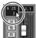
6 Drag the Pan controls on the left side of the channel strips left and right to set the stereo position of each track.
Pan Effectively
"Panning" creates the illusion of stereo space by changing the relative levels of each track's signal sent to the left and right speakers. If a signal is sent only to the left speaker, the sound will appear to come from the far left side of the stereo sound field. If it sent with equal level to both left and right speakers our ears tell us the sound is located in the center of the stage. Judicious panning can also help to create cleaner-sounding mixes by spreading the instruments out across the sound stage so that they don't "get in each other's way." There are no hard and fast rules, but the bass and kick drum are usually placed in the center of the mix, as is the lead instrument or vocal. Other instruments should be evenly balanced throughout the sound stage in a well-balanced manner.
7 At this point you can begin to use EQ to refine your mix, and add effects.
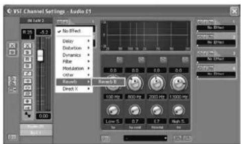
As an example let's try adding reverb. Click the [Edit VST channel] button (on the left side of the channel strip to open the VST Channel Settings window. Click No Effect → Reverb → Reverb B.
NOTE For further details refer to the pdf manual provided with the Cubase LE software.
It's a good idea to lower the channel fader a bit before adding an effect, since the effect can cause an increase in the overall channel level.
8 When the final adjustments have been made to the mix, go to the [File] menu and select [Export] → [Audio Mixdown].
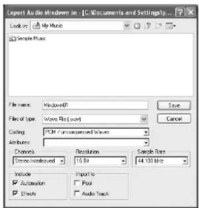
9 Enter a file name and select a file type.
If you intend to use the file to create an audio CD, select the WAV file type (AIFF on a Macintosh), Stereo Interleaved, 16 bit, and 44.1 kHz.
10 Click [Save].
Progress of the mixdown operation will be shown in a progress window. When the progress window closes the mixdown is complete.
5NOTE Wave files created by mixdown can be directly playback back using the Windows Media Player or iTunes on a Macintosh computer.
Front & Rear Panels
Channel Control Section

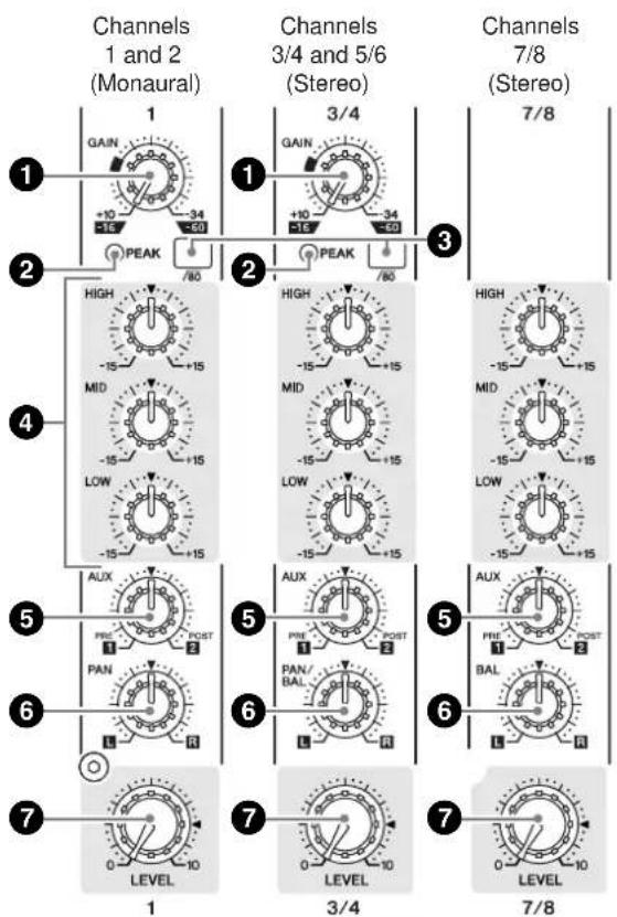
①GAIN Control
Adjusts the input signal level. To get the best balance between the S/N ratio and the dynamic range, adjust the level so that the PEAK indicator (②) comes on only at about maximum input level.
The -60 to -16 scale indicates the MIC input adjustment level. The -34 to +10 scale indicates the LINE input adjustment level.
②PEAK Indicator
Detects the peak level of the post-EQ signal, and lights up red when the level reaches 3 dB below the clipping level. For XLR-equipped stereo input channels (3/4 and 5/6), detects both post-EQ and post-mic-amp peak levels, and lights red if either of these levels reaches 3 dB below the clipping level.
NOTE When the level of an input signal exceeds the level that can be handled by the mixer's head amp or equalizer, distortion and noise will result. The PEAK indicators are used to visually check the signal level to ensure no overload occurs.
③ Switch (High Pass Filter)
This switch toggles the HPF on or off. To turn the HPF on, press the switch in (The HPF cuts frequencies below 80 Hz. (But note that regardless of the switch setting, the mixer does not apply this HPF to the line inputs of stereo input channels.)
④ Equalizer (HIGH, MID, and LOW)
This three-band equalizer adjusts the channel's high, mid, and low frequency bands. Setting the knob to the ▼ position produces a flat frequency response. Turning the knob to the right boosts the corresponding frequency band, while turning to the left attenuates the band. The following table shows the EQ type, base frequency, and maximum cut/boost for each of the three bands.
| Band Type | Base Frequency | Maximum Cut/Boost | |
| HIGH Shelving 10 kHz | ±15 dBMID Pe | ||
| LOW Shelving 100 Hz | |||
NOTE The equalizer can be used to boost or cut specific frequency bands, allowing the tone of the sound to be shaped as required by the mix.
⑤AUX Controls
Use the AUX control to send the channel's signal to the AUX1or AUX2 bus.
Turn the knob to the left of the “▼” mark to feed the signal to the AUX1 bus, or to the right of the “▼” to feed to the AUX2 bus. The volume of the feed increases as you move the knob away from the “▼” position. If you set the knob exactly to the “▼” position, the mixer will not send the signal to either of the AUX buses.
Note that the signal to the AUX1 bus is a pre-fader signal, and is not affected by the channel LEVEL controls. The signal to the AUX2 bus is a post-fader signal, and will always pass through the channel LEVEL controls before moving to the bus.
If you are using stereo channels, the signals from the L (odd) and R (even) channels are mixed and sent to the AUX1 and AUX2 buses.
⑥PAN Control (CHs 1 and 2) PAN/BAL Control (CHs 3/4 and 5/6) BAL Control (CHs 7/8, 9/10)
The PAN control determines the positioning of the channel's signal on the Stereo L and R buses. The BAL control knob sets the balance between left and right channels. Signals into the L input (odd channel) feed to the Stereo L bus; signals into the R input (even channel) feed to the Stereo R bus.
NOTE On channels where this knob provides both PAN and BAL controls: The knob operates as a PAN control if you are inputting through the MIC jack or into the L (MONO) input only, and operates as a BAL control if you are inputting into both L and R inputs.
⑦Channel LEVEL Control
Adjusts the output level of the signal being input to the channel. Use these LEVEL Controls to adjust the volume balance among the various channels.
NOTE To reduce noise, set the LEVEL Control knobs for unused channels all the way to the left (to the minimum setting).
Master Control Section
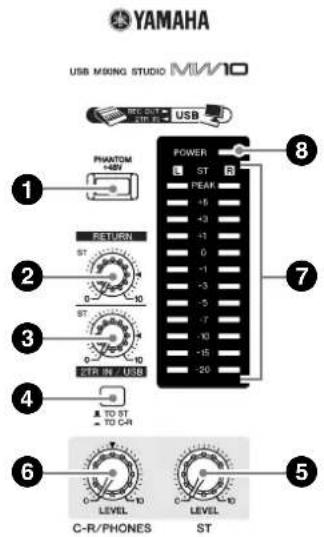
①PHANTOM +48 V Switch
This switch toggles phantom power on and off. If you set the switch on, the mixer supplies power to all channels that provide XLR mic input jacks (CHs 1, 2, 3/4, 5/6). Set this switch on ( ) when using one or more condenser microphones.
NOTE When this switch is on, the mixer supplies DC +48 V power to pins 2 and 3 of all XLR-type MIC INPUT jacks.

- Be sure to leave this switch off ( ) if you do not need phantom power.
- When tuning the switch on ( ) be sure that only condenser mics are connected to the XLR input jacks (CHs: 1 to 5/6). Devices other than condenser mics may be damaged if connected to the phantom power supply. Note, however, that the switch may be left on without problem when connecting to balanced dynamic microphones.
- To avoid damage to speakers, be sure to turn off amplifiers (or powered speakers) before turning this switch on or off. We also recommend that you turn all output controls (ST Master LEVEL Control, etc.) to minimum settings before operating the switch, to avoid risk of loud noises that could cause hearing loss or device damage.
②RETURN Control
Adjusts the level of the signal sent from the RETURN jacks (L (MONO) and R) to the Stereo bus.
NOTE If you supply a signal to the RETURN L (MONO) jack only, the mixer outputs the identical signal to both the L and R Stereo buses.
③2TR IN/USB Control
Adjusts the level of signals received via 2TR IN, as well as the level of signals received by the MW10 from the computer via the USB interface.
④2TR IN/USB Switch (TO ST/TO C-R)
Determines whether the stereo signal received via the 2TR IN connectors or USB interface is sent to the stereo bus or the C-R OUT connectors and PHONES jack (level meter).
NOTE • When the 2TR IN/USB switch is set to TO ST, the signal input via the 2TR IN/USB connector is added to the stereo bus.
- When the 2TR IN/USB switch is set to TO C-R, the signal input via the 2TR IN/USB connector is directly sent to the C-R OUT/PHONES connector, and is not output via the stereo bus.
⑤ST Master LEVEL Control
Adjusts the signal level to the ST OUT jacks.
⑥C-R/PHONES LEVEL Control
Controls the level of the signal output to the PHONES jack and the C-R OUT L and R jacks.
⑦Level Meter
This LED display shows the level of the signal fed to the Stereo bus. The "0" point corresponds to the standard output level. The indicator lights up red when the output hits the clipping level.
8 POWER Indicator
This indicator lights up when the mixer's power is ON.
Input/Output Section
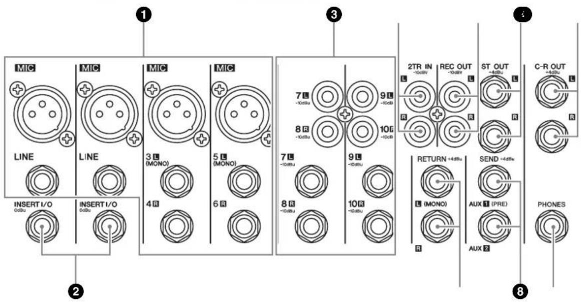
①Channel Input Jacks (CHs 1, 2, 3/4, 5/6)
- MIC jacks These are balanced XLR-type input jacks (1:Ground; 2:Hot; 3:Cold).
• LINE jacks These are balanced phone-type input jacks. You can connect either balanced or unbalanced phone plugs to these jacks.
NOTE Where an input channel provides both a MIC jack and a LINE jack, you may use either one of these jacks but you may not use both at the same time. Please connect to only one of these jacks on each channel.
② INSERT I/O Jacks (CHs 1 and 2)
These are unbalanced phone-type input/output jacks. Each of these jacks is positioned between the equalizer and Channel LEVEL Control of the corresponding input channel. These jacks can be used to independently connect these channels to devices such as graphic equalizers, compressors, and noise filters. These are TRS (tip, ring, sleeve) phone jacks that support bidirectional operation.
NOTE Connection to an INSERT I/O jack requires a special separately-sold insertion cable such as illustrated below.
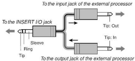
flowchart
graph LR
    A["To the INSERT I/O jack"] --> B["Sleeve"]
    B --> C["Tip: In"]
    B --> D["Ring"]
    B --> E["Sleeve"]
    E --> F["Tip: Out"]
    G["To the input jack of the external processor"] --> H["Tip: Out"]
    G --> I["Tip: In"]
    G --> J["Output jacks"]
NOTE The signal output from the INSERT I/O jacks is reverse-phased. This will not be a problem if connecting the jack to an effector. If using the jack to output to an external device, however, please be aware of possible phase conflicts with other signals.
③Channel Input Jacks (CHs 7/8, 9/10)
Each of these channel pairs can be used to input a stereo source signal. For each pair, the odd-numbered channel inputs the L signal, and the even-numbered channel inputs the R signal.
Each channel offers a choice of two jack types: phone jack and RCA pin jack. All of these jacks are unbalanced.
NOTE Where a channel provides both phone jacks and RCA pin jacks, you may use either one of these jacks but you may not use both at the same time. Please connect to only of these jacks on each channel.
④2TR IN Jacks
These are unbalanced RCA-pin input jacks. Use these jacks when you want to connect a stereo sound source (CD, DAT, etc.) directly to the mixer for monitoring.
NOTE • You can adjust the signal level using the 2TR IN/USB control in the Master Control section.
- When a signal is being received both via the 2TR IN connectors and the USB interface, the received signals are mixed.
⑤REC OUT (L, R) Jacks
These are unbalanced RCA-pin output jacks. These jacks output the mixed signal whose level is controlled by the ST Master LEVEL Control. You use these jacks, for example, to connect to an external recorder.
NOTE These connectors output the same signal that sent to the computer via the USB interface.
⑥ST OUT (L, R) Jacks
These are impedance-balanced phone-type output jacks. These jacks output the mixed signal whose level is controlled by the ST Master LEVEL Control. You use these jacks, for example, to connect to the power amplifier driving your main speakers.
⑦C-R OUT Jacks
These are impedance-balanced phone-type output jacks. These jacks output the mixed signal whose level is controlled by the C-R/PHONES LEVEL Control. You use these jacks, for example, to connect to the powered speaker.
NOTE When the 2TR IN/USB switch is set to TO C-R, the signal input via the 2TR IN/USB connector and the stereo bus signal are mixed and output via the C-R OUT/PHONES connector.
8SEND Jacks
• A UX1, AUX2
These are impedance balanced phone-type output jacks.
These jacks output the signals from AUX1 and AUX2, respectively. You use these jacks, for example, to connect to an effector or monitor system.
⑨RETURN L (MONO), R Jacks
These are unbalanced phone-type input jacks. The signal received by these jacks is sent to the Stereo bus. These jacks are typically used to receive a return signal from an external effector (reverb, delay, etc.).
NOTE These jacks can also be used as an auxiliary stereo input. If you connect to the L (MONO) jack only, the mixer will recognize the signal as monaural and will propagate the identical signal on both L and R jacks.
10PHONES Jack
Connector for headphones. This is a stereo phone-type output jack.
NOTE When the 2TR IN/USB switch is set to TO C-R, the signal input via the 2TR IN/USB connector and the stereo bus signal are mixed and output via the C-R OUT/PHONES connector.
Connector Polarities
| MIC INPUT | Pin 1: GroundPin 2: Hot (+)Pin 3: Cold (-) | INPUT OUTPUT  |
| LINE INPUT (monaural channels),ST OUT, C-R OUT,AUX1, AUX2* | Tip: Hot (+)Ring: Cold (-)Sleeve: Ground | Ring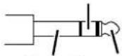 Sleeve Tip Sleeve Tip |
| INSERT I/O | Tip: OutputRing: InputSleeve: Ground | |
| PHONES | Tip: LRing: RSleeve: Ground | |
| RETURN, LINE INPUT (stereo channels) | Tip: HotSleeve: Ground | 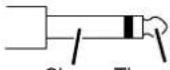 Sleeve Tip Sleeve Tip |
* These jacks will also accept connection to monaural phone plugs. If you use monaural plugs, the connection will be unbalanced.
Rear Section
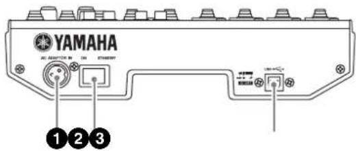
①AC ADAPTOR IN Connector
Connects to the included PA-10 power adaptor (see page 6).

Use only the PA-10 adaptor included with this mixer. Use of a different adaptor may result in fire or electric shock.
②POWER Switch
Use this switch to set mixer power to ON or STANDBY.

Note that trace current continues to flow while the switch is in the STANDBY position. If you do not plan to use the mixer again for a long while, be sure to unplug the adaptor from the wall outlet.
③USB Connector
Connects to the computer via the supplied USB cable.

When connecting or disconnecting the USB cable be sure to turn the 2TR IN/USB control all the way down.
Setting Up
Setup Procedure
1 Before connecting to microphones and instruments, be sure that all devices are turned off. Also be sure that all of the channel controls and all of the controls in the Master Control section are turned to their minimum settings.
2 For each connection, connect one end of the cable to the relevant microphone or instrument and connect the other end to the appropriate input jack on the mixer.
5 NOTE Where an input channel provides both a MIC INPUT jack and a LINE INPUT jack, you may use either one of these jacks but you may not use both at the same time. Please connect to only one of these jacks on each channel.
3 To avoid causing damage to speakers, power up the devices in the following order: Peripheral devices → mixer → power amps (or powered speakers).
5 NOTE When shutting the system down, turn off the power in the opposite order: Power amps (powered speakers) → mixer → peripheral devices.
Setup Examples
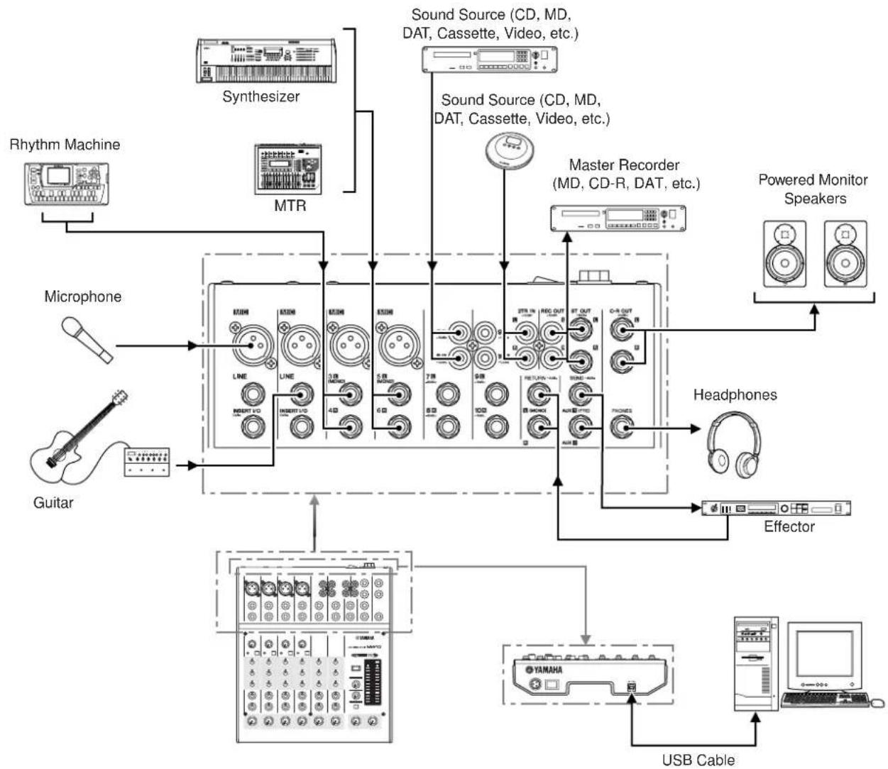
flowchart
graph TD
    A["Rhythm Machine"] --> B["Synthesizer"]
    B --> C["MTR"]
    C --> D["Sound Source (CD, MD, DAT, Cassette, Video, etc.)"]
    D --> E["Master Recorder (MD, CD-R, DAT, etc.)"]
    E --> F["Powered Monitor Speakers"]
    G["Guitar"] --> H["Microphone"]
    H --> I["Line"]
    H --> J["LIME"]
    H --> K["INSERT V/D"]
    H --> L["INSERT V/D"]
    H --> M["4Ω"]
    H --> N["6Ω"]
    H --> O["7Ω"]
    H --> P["8Ω"]
    H --> Q["9Ω"]
    H --> R["10Ω"]
    H --> S["11Ω"]
    H --> T["12Ω"]
    H --> U["13Ω"]
    H --> V["14Ω"]
    H --> W["15Ω"]
    H --> X["16Ω"]
    H --> Y["17Ω"]
    H --> Z["18Ω"]
    H --> AA["19Ω"]
    H --> AB["20Ω"]
    H --> AC["21Ω"]
    H --> AD["22Ω"]
    H --> AE["23Ω"]
    H --> AF["24Ω"]
    H --> AG["25Ω"]
    H --> AH["26Ω"]
    H --> AI["27Ω"]
    H --> AJ["28Ω"]
    H --> AK["29Ω"]
    H --> AL["30Ω"]
    H --> AM["31Ω"]
    H --> AN["32Ω"]
    H --> AO["33Ω"]
    H --> AP["34Ω"]
    H --> AQ["35Ω"]
    H --> AR["36Ω"]
    H --> AS["37Ω"]
    H --> AT["38Ω"]
    H --> AU["39Ω"]
    H --> AV["40Ω"]
    H --> AW["41Ω"]
    H --> AX["42Ω"]
    H --> AY["43Ω"]
    H --> AZ["44Ω"]
    H --> BA["45Ω"]
    H --> BB["46Ω"]
    H --> BC["47Ω"]
    H --> BD["48Ω"]
    H --> BE["49Ω"]
    H --> BF["50Ω"]
    H --> BG["51Ω"]
    H --> BH["52Ω"]
    H --> BI["53Ω"]
    H --> BJ["54Ω"]
    H --> BK["55Ω"]
    H --> BL["56Ω"]
    H --> BM["57Ω"]
    H --> BN["58Ω"]
    H --> BO["59Ω"]
    H --> BP["60Ω"]
    H --> BQ["61Ω"]
    H --> BR["62Ω"]
    H --> BS["63Ω"]
    H --> BT["64Ω"]
    H --> BU["65Ω"]
    H --> BV["66Ω"]
    H --> BW["67Ω"]
    H --> BX["68Ω"]
    H --> BY["69Ω"]
    H --> BZ["70Ω"]
    H --> CA["71Ω"]
    H --> CB["72Ω"]
    H --> CC["73Ω"]
    H --> CD["74Ω"]
    H --> CE["75Ω"]
    H --> CF["76Ω"]
    H --> CG["77Ω"]
    H --> CH["78Ω"]
    H --> CI["79Ω"]
    H --> CJ["80Ω"]
    H --> CK["81Ω"]
    H --> CL["82Ω"]
    H --> CM["83Ω"]
    H --> CN["84Ω"]
    H --> CO["85Ω"]
    H --> CP["86Ω"]
    H --> CQ["87Ω"]
    H --> CR["88Ω"]
    H --> CS["89Ω"]
    H --> CT["90Ω"]
    H --> CU["91Ω"]
    H --> CV["92Ω"]
    H --> CW["93Ω"]
    H --> CX["94Ω"]
    H --> CY["95Ω"]
    H --> CZ["96Ω"]
    H --> DA["97Ω"]
    H --> DB["98Ω"]
    H --> DC["99Ω"]
    H --> DD["100Ω"]

    E --> E1["Pioneer Monitor Speakers"]

    F["Guitar"] --> G
    G --> G
    G --> G
    G --> G
    G --> G
    G --> G
    G --> G
    G --> G
Troubleshooting
The MW10 mixer won't turn on.
- Is the supplied power adaptor properly plugged into both the mixer and an appropriate AC wall outlet?
The system doesn't work properly.
- Are the USB cable and all necessary audio cables properly connected?
- Are you using a USB hub?
USB hubs can interfere with proper operation, so try connecting the MW10 directly to a USB port on the computer. If the computer has multiple USB ports, try a different USB port.
- Are you using other USB devices at the same time?
If so, try removing the other device(s) and connecting only the Yamaha USB device.
No sound.
- Are your speaker cables connected properly, or are they shorted?
- Are the volume controls of your sources, audio devices, applications software, computer operating system, etc., set at appropriate levels?
- Is the output of your computer operating system muted?
- Do you have several applications running at the same time?
Be sure to quit all applications you are not using.
- Is the sound output of your computer operating system assigned properly?
Windows:
1 From the [Start] menu click [Control Panel], then double-click "Sounds and Audio Devices" icon to open the "Sounds and Audio Devices Properties" dialog window.
2 Click the "Audio" tab.
3 Set "Sound playback: Default device" and "Sound recording: Default device" to "USB Audio CODEC."
4 Click [OK].
Macintosh:
1 Select [System Preferences ...] from the Apple menu and then select "Sound" to open the "Sound" dialog window.
2 Click the "Input" tab and under "Choose a device for sound input" select "USB Audio CODEC."
3 Click the "Output" tab and under "Choose a device for sound output" select "USB Audio CODEC."
- Is the sound output of the Cubase LE application assigned properly?
For setup details refer to page 10 of the Quick Guide.
The recorded sound is too low in level.
- Is the computer's output level setting too low?
We recommend that you set the computer output to the maximum level.
Windows:
1 From the [Start] menu click [Control Panel], then double-click "Sounds and Audio Devices" icon to open the "Sounds and Audio Devices Properties" dialog window.
2 Double click the "Volume" tab.
3 Set "Device volume" to "High".
Macintosh:
1 Select [System Preferences ...] from the Apple menu and then select "Sound" to open the "Sound" dialog window.
2 Click the "Output" tab and set the volume slider at the bottom of the window to it's maximum level.
- Have you connected or disconnected the USB cable while Cubase LE is running?
Doing so can sometimes cause the Windows output level to be reset to its default level. Check and raise the output level if necessary.
The sound is intermittent or distorted.
• Is the PEAK indicator flashing red?
You might have to lower GAIN control or channel LEVEL control levels to avoid distortion.
- Does the computer you are using meet the listed system requirements?
Refer to "System Requirements" on page 6 for details.
- Are any other applications, device drivers, or USB devices (scanners, printers, etc.) running at the same time?
Be sure to quit all applications you are not using.
- Are you playing back a large number of audio tracks?
The number of tracks you can play at the same time will depend on the performance of the computer you are using. You may experience intermittent playback if you exceed your computer's capabilities.
- Are you recording or playing long continuous sections of audio?
The audio data processing capabilities of your computer will depend on a number of factors including CPU speed and access to external devices.
On Windows computers, changing some settings as outlined below can improve performance.
1 Click [Control Panel] from the [Start] menu, and double click the "Sounds and Audio Devices" icon to open the "Sounds and Audio Devices Properties" dialog.
2 Click the "Volume" tab and click [Advanced] in "Speaker Settings". The "Advanced Audio Properties" dialog will open.
3 Click the "Performance" tab. Set "Hardware Acceleration" to "Full", and "Sample Rate Conversion Quality" to "Good."
Don't change these settings if you are not familiar with your computer's operating system.
Check that the file system is set properly, and make sure that you have a plenty of free memory (more than 128 MB). If the wave files you are recording or playing are not too large, changing the virtual memory settings can sometimes improve audio performance. In some cases it might be necessary to update your hard disk controller, device drivers, or BIOS. Refer to your computer's support center or support page on the web for more information.
- Try adding memory.
Adding more RAM memory can significantly increase your computer's audio performance. Refer to your computer's owner's manual for information on installing and setting up extra memory.
There is a delay when playing a software synthesizer via a MIDI keyboard (latency).
- Check the URL listed below for the latest information. http://www.yamahasynth.com/
Appendix
Specifications
■ Electrical Characteristics
| Conditions MIN TYP | MAX | UNIT | |||
| Total Harmonic Distortion(MIC to ST OUT) | (THD+N) 20 Hz - 20 kHz @ +14 dBu 10k ohms, GAIN controls at minimum level, all level controls at nominal level | 0.1 % | |||
| Frequency Response(CH INPUT 1-9/10, RETURN, 2TR IN to ST OUT, AUX SEND, C-R OUT, REC OUT) | 20 Hz-20 kHz, nominal output level @ 1 kHz, 10 k ohms, GAIN controls at minimum level (CH INPUT 1-5/6), all level controls at nominal level | -301 dB | |||
| Hum & NoiseRs=150 ohms, Gain=Maximum (CH INPUT 1-2), Hum & Noise are measured with a -6 dB/octave filter @12.7 kHz; equivalent to a 20 kHz filter with infinite dB/octave attenuation. | Equivalent Input Noise (CH INPUT 1-2 MIC) -128 dBu | ||||
| Residual Output Noise (10 k ohms (ST OUT)) -100 dBu | |||||
| ST master control at nominal level and all channel LEVEL controls at minimum level. (ST OUT) | -87(91 dB S/N) | dBu | |||
| All channel AUX controls at minimum level. (AUX SEND) | -85(89 dB S/N) | dBu | |||
| ST master control and one channel LEVEL control at nominal level. (CH INPUT 1, 2) (ST OUT) | -64(68 dB S/N) | dBu | |||
| Maximum Voltage Gain1 kHz, 10k ohmsPAN/BAL: panned hard left or hard right. | CH INPUT 1, 2 MIC to CH INSERT OUT, Rs=150 ohms, GAIN controls at maximum level | 60 dB | |||
| CH INPUT 1-5/6 MIC to ST OUT, Rs=150 ohms, GAIN controls at maximum level | 76 dB | ||||
| CH INPUT 1-5/6 MIC to REC OUT, Rs=150 ohms, GAIN controls at maximum level | 64.2 dB | ||||
| CH INPUT 1, 2 MIC to AUX SEND, Rs=150 ohms, GAIN controls at maximum level, PRE | 70 dB | ||||
| CH INPUT 1, 2 MIC to AUX SEND, Rs=150 ohms, GAIN controls at maximum level, POST | 76 dB | ||||
| CH INPUT 3/4-5/6 LINE to ST OUT, Rs=150 ohms, GAIN controls at maximum level | 50 dB | ||||
| CH INPUT 3/4-5/6 LINE to AUX SEND, Rs=150 ohms, GAIN controls at maximum level, PRE | 41 dB | ||||
| CH INPUT 3/4-5/6 LINE to AUX SEND, Rs=150 ohms, GAIN controls at maximum level, POST | 47 dB | ||||
| CH INPUT 7/8-9/10 to ST OUT, Rs=150 ohms, GAIN controls at maximum level | 26 dB | ||||
| RETURN to ST OUT, Rs=150 ohms | 12 dB | ||||
| 2TR IN to ST OUT, Rs=600 ohms | 23.8 dB | ||||
| Crosstalk (1 kHz) | Adjacent inputs | -70 | dB | ||
| input to output | -70 | dB |
Where 0 dBu = 0.775 Vrms
Output impedance of signal generator: 150 ohms
■ General Specifications
| Monaural/Stereo CH High Pass Filter | 80 Hz 12 dB/octave |
| Monaural/Stereo CH EqualizationTurn over/roll-off frequency of shelving, 3 dB below maximum variable level | ±15 dB (Max. Variation)HIGH: 10 kHz (shelving)MID: 2.5 kHz (peaking)LOW: 100 Hz (shelving) |
| Phantom Power | Supplied when Phantom +48 V switch is ON. (XLR-type input jacks) |
| Monaural/Stereo Input PEAK Indicator | On each channel: red indicator lights if post-EQ signal (on stereo channels, if either post-EQ signal or post-mic-amp signal) comes within 3 dB of the clipping level. |
| USB Audio | Input/Output: 44.1/48 kHz |
| Included Accessories | Power adaptor (PA-10), CD-ROM, USB cable, Owner's manual |
| Power Consumption | 19 W |
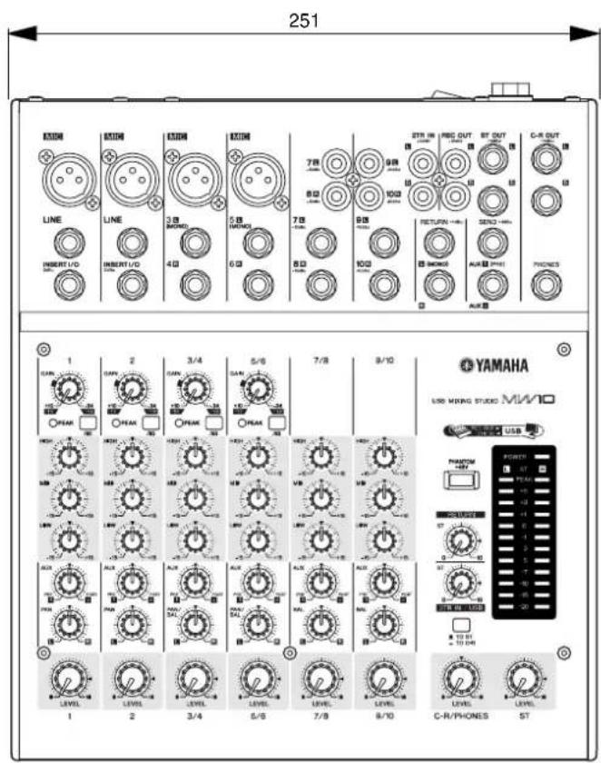
| Dimensions (W · H · D) | 251 mm · 65 mm · 290.5 mm |
| Net Weight | 1.8 kg |
| Temperature Range | Operating temperature: 0 to 40 °C, Storage temperature: -20 to 60 °C |
■ Analog Input Specifications
| Input Connector Gain | Input Impedance | Appropriate Impedance | Sensitivity* | Nominal Level | Max. Before Clipping | Connector Specifications | |
| MIC INPUT(CH 1, 2) | -60 | 3 k ohms 50 | -600 ohms mic | -72 dBu(0.195 mV) | -60 dBu(0.775 mV) | -40 dBu(7.75 mV) | XLR-3-31 type (balanced) |
| -16 | -28 dBu(30.8 mV) | -16 dBu(123 mV) | +4 dBu(1.23 V) | ||||
| LINE INPUT(CH 1, 2) | -34 | 10 k ohms 600 ohms line | -46 dBu(3.88 mV) | -34 dBu(15.5 mV) | -14 dBu(155 mV) | Phone jack (TRS)(balanced [T: hot; R:cold;S: ground]) | |
| +10 | -2 dBu(0.615 V) | +10 dBu(2.45 V) | +30 dBu(24.5 V) | ||||
| ST CH MIC INPUT(CH3(L)/CH4(R),CH5(L)/CH6(R)) | -60 | 3 k ohms 50 | -600 ohms mic | -72 dBu(0.195 mV) | -60 dBu(0.775 mV) | -40 dBu(7.75 mV) | XLR-3-31 type (balanced) |
| -16 | -28 dBu(30.8 mV) | -10 dBu(245 mV) | |||||
| ST CH LINE INPUT(CH3(L)/CH4(R),CH5(L)/CH6(R)) | -34 | 10 k ohms 600 ohms line | -46 dBu(3.88 mV) | -34 dBu(15.5 mV) | -14 dBu(155 mV) | Phone jack (unbalanced) | |
| +10 | -2 dBu(0.615 V) | +10 dBu(2.45 V) | +30 dBu(24.5 V) | ||||
| ST CH INPUT(CH7(L)/CH8(R),(CH9(L)/CH10(R)) | 10 k ohms 600 ohms line | -22 dBu(61.5 mV) | -10 dBu(245 mV) | +10 dBu(2.45 V) | Phone jack (unbalanced);RCA pin jack | ||
| CH INSERT IN(CH 1, 2) | 10 k ohms 600 ohms line | -12 dBu(195 mV) | 0 dBu(0.775 V) | +20 dBu(7.75 V) | Phone jack (TRS)(unbalanced[T: out; R: in;S: ground]) | ||
| RETURN (L, R) | 10 k ohms 600 ohms line | -8 dBu(308 mV) | +4 dBu(1.23 V) | +24 dBu(12.3 V) | Phone jack (unbalanced) | ||
| 2TR IN (L, R) | 10 k ohms 600 ohms line | -22 dBV(79.4 mV) | -10 dBV(316 mV) | +10 dBV(3.16 V) | RCA pin jack | ||
Where 0 dBu=0.775 Vrms and 0 dBV=1 Vrms
* Input sensitivity: the lowest level that will produce an output of +4 dBu (1.23V) or the nominal output level when the unit is set to maximum gain. (All level controls are maximum position.)
■ Analog Output Specifications
| Output Connectors Output Impedance | Appropriate Impedance | Nominal Level | Max. Before Clipping | Connector Specifications | |
| ST OUT (L, R) | 150 ohms 10 k ohms | ine +4 dBu (1.23 V) +20 dBu (7.75 V) | Phone jack (TRS)(impedance balanced[T: hot; R: cold; S: ground]) | ||
| AUX SEND (1, 2) | 150 ohms 10 k ohms | ine +4 dBu (1.23 V) +20 dBu (7.75 V) | Phone jack (TRS)(impedance balanced[T: hot; R: cold; S: ground]) | ||
| CH INSERT OUT(CH 1, 2) | 150 ohms 10 k ohms | ine 0 dBu (0.775 V) +20 dBu (7.75 V) | Phone jack (TRS)(unbalanced [T: out; R: in;S: ground]) | ||
| REC OUT (L, R) | 600 ohms 10 k ohms | ine -10 dBV (316 mV) +10 dBV (3.16 V) RCA pin jack | |||
| C-R OUT (L, R) | 150 ohms 10 k ohms | ine +4 dBu (1.23 V) +20 dBu (7.75 V) | Phone jack (TRS)(impedance balanced[T: hot; R: cold; S: ground]) | ||
| PHONES | 100 ohms 40 ohms phone 3 mW 75 mW Stereo phone jack | ||||
Where 0 dBu=0.775 Vrms and 0 dBV=1 Vrms
■ Digital Input/Output Specifications
| Connector | Format | Data Length | Connector Specification |
| USB | USB Audio 1.1 | 16 bit | USB B type |
Dimensional Diagrams
Block Diagram and Level Diagram
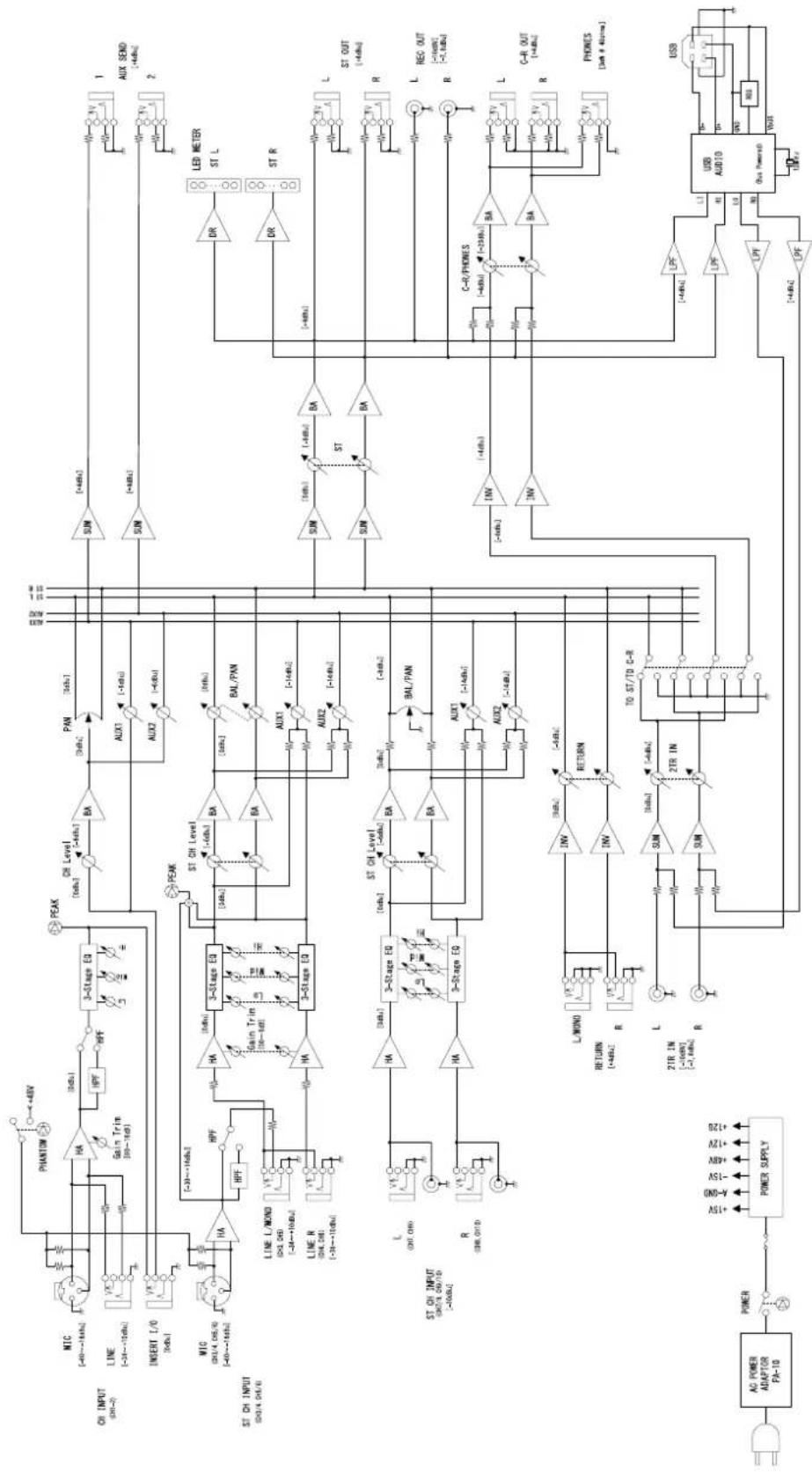
flowchart
graph TD
    subgraph Power Supply
        A["AC POWER ADAPTOR FA-10"] --> B["POWER"]
        B --> C["+15V 4.8V 15V 48V 12V 120"]
    end

    subgraph ST ON INPUT
        D["L (OH, OH)"]
        E["R (3W, OT)D"]
    end

    subgraph ST CH INPUT
        F["L (OH, OH)"]
        G["LINE R (DA, DB)"]
    end

    subgraph LED METER
        H["BR"]
        I["DR"]
        J["LED METER ST L"]
    end

    subgraph USB Audio
        K["USB"]
        L["USB AUDIO"]
    end

    subgraph Power Supply
        M["AC POWER ADAPTOR FA-10"] --> N["POWER"]
        N --> O["+15V 4.8V 15V 48V 12V 120"]
    end

    subgraph ST ON INPUT
        P["LINE L/MOND (DX, OH) (-34~+10dB)"]
        Q["LINE R (DA, DB) (-34~+10dB)"]
    end

    subgraph ST CH INPUT
        R["Line L/MOND (DX/4, OH)/TO (-10dB)"]
        S["Line R (DA, DB) (-34~+10dB)"]
    end

    subgraph LED METER
        T["AUX1"]
        U["AUX2"]
        V["AUX3"]
        W["AUX4"]
        X["AUX5"]
        Y["AUX6"]
        Z["AUX7"]
        AA["AUX8"]
        AB["AUX9"]
        AC["AUX10"]
        AD["AUX11"]
        AE["AUX12"]
        AF["AUX13"]
        AG["AUX14"]
        AH["AUX15"]
        AI["AUX16"]
        AJ["AUX17"]
        AK["AUX18"]
        AL["AUX19"]
        AM["AUX20"]
        AN["AUX21"]
        AO["AUX22"]
        AP["AUX23"]
        AQ["AUX24"]
        AR["AUX25"]
        AS["AUX26"]
        AT["AUX27"]
        AU["AUX28"]
        AV["AUX29"]
        AW["AUX30"]
        AX["AUX31"]
        AY["AUX32"]
        AZ["AUX33"]
        BA["AUX34"]
        BB["AUX35"]
        BC["AUX36"]
        BD["AUX37"]
        BE["AUX38"]
        BF["AUX39"]
        BG["AUX40"]
    end

    subgraph Power Supply
        BH["PHANTOM"] --> BI["+48V"]
        BI --> BJ["HA Gain Trim (30~+1cd)"]
        BJ --> BK["HPF Gain Trim (30~+1cd)"]
        BK --> BL["3-Stage EQ"]
        BL --> BM["PEAK"]
        BM --> BN["CH Level (-6dB)"]
        BN --> BO["BA"]
        BO --> BP["PAN (-6dB)"]
        BP --> BQ["SUN (-4dB)"]
        BQ --> BR["SUN (-4dB)"]
        BS["SUN (-4dB)"] --> BT["SUN (-4dB)"]
    end

    subgraph ST ON INPUT
        BU["ST CH INPUT (DX/4, OH)/T"] --> BV["HA Gain Trim (30~+1cd)"]
        BV --> BW["HPF Gain Trim (30~+1cd)"]
        BW --> BX["HA Gain Trim (30~+1cd)"]
        BX --> BY["3-Stage EQ"]
        BY --> BZ["PEAK"]
        BZ --> CA["CH Level (-6dB)"]
        CA --> CB["BA"]
        CB --> CC["BAL/PAN (-6dB)"]
        CC --> CD["SUN (-4dB)"]
        CD --> CE["SUN (-4dB)"]
        CF["SUN (-4dB)"] --> CG["SUN (-4dB)"]
    end

    subgraph ST CH INPUT
        CHL["LINE L/MOND (DX/4, OH) (-34~+10dB)"]
        CI["LINE R (DA, DB) (-34~+10dB)"]
    end

    subgraph ST ON INPUT
        CJ["L (OH, OH)"]
        CK["R (3W, OT)D"]
    end

    subgraph ST CH INPUT
        CL["L (OH, OH)"]
        DD["R (3W, OT)D"]
    end

    subgraph LED METER
        DE["BR"] --> DF["SUN (-4dB)"]
        DF --> DG["SUN (-4dB)"]
    end

    subgraph USB Audio
        DH["USB AUDIO"] --> DI["USB Audio"]
    end

    subgraph Power Supply
        DJ["INV"] --> DK["SUN (-4dB)"]
        DK --> DL["SUN (-4dB)"]
    end

    subgraph Power Supply
        DJL["L/WONO"] --> DJL
        DJR["RETURN (+4dB)"] --> DJR
        DJK["2TR IN (-6dB)"] --> DJK
        DJL["2TR IN (-7dB)"] --> DJL
    end

    subgraph ST ON INPUT
        DJL --> DJL
    end

    subgraph ST CH INPUT
        DJL --> DJL
    end
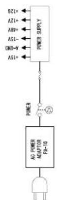
flowchart
graph LR
    A["AC POWER ADAPTOR PA-10"] --> B["POWER"]
    B --> C["POWER SUPPLY"]
    C --> D["+12V"]
    C --> E["-15V"]
    C --> F["+40V"]
    C --> G["+12V"]
    C --> H["+15V"]

ATTENTION
SOFTWARE LICENSE AGREEMENT
PLEASE READ THIS SOFTWARE LICENSE AGREEMENT ("AGREEMENT") CAREFULLY BEFORE USING THIS SOFTWARE. YOU ARE ONLY PERMITTED TO USE THIS SOFTWARE PURSUANT TO THE TERMS AND CONDITIONS OF THIS AGREEMENT. THIS AGREEMENT IS BETWEEN YOU (AS AN INDIVIDUAL OR LEGAL ENTITY) AND YAMAHA CORPORATION ("YAMAHA").
BY BREAKING THE SEAL OF THIS PACKAGE YOU ARE AGREEING TO BE BOUND BY THE TERMS OF THIS LICENSE. IF YOU DO NOT AGREE WITH THE TERMS, DO NOT INSTALL, COPY, OR OTHERWISE USE THIS SOFTWARE.
1. GRANT OF LICENSE AND COPYRIGHT
Yamaha hereby grants you the right to use one copy of the software program(s) and data ("SOFTWARE") accompanying this Agreement. The term SOFTWARE shall encompass any updates to the accompanying software and data. The SOFTWARE is owned by Yamaha and/or Yamaha's licensor(s), and is protected by relevant copyright laws and all applicable treaty provisions. While you are entitled to claim ownership of the data created with the use of SOFTWARE, the SOFTWARE will continue to be protected under relevant copyrights.
- You may use the SOFTWARE on a single computer.
- You may make one copy of the SOFTWARE in machine-readable form for backup purposes only, if the SOFTWARE is on media where such backup copy is permitted. On the backup copy, you must reproduce Yamaha's copyright notice and any other proprietary legends that were on the original copy of the SOFTWARE.
- You may permanently transfer to a third party all your rights in the SOFTWARE, provided that you do not retain any copies and the recipient reads and agrees to the terms of this Agreement.
2. RESTRICTIONS
- You may not engage in reverse engineering, disassembly, decompilation or otherwise deriving a source code form of the SOFTWARE by any method whatsoever.
- You may not reproduce, modify, change, rent, lease, or distribute the SOFTWARE in whole or in part, or create derivative works of the SOFTWARE.
- You may not electronically transmit the SOFTWARE from one computer to another or share the SOFTWARE in a network with other computers.
- You may not use the SOFTWARE to distribute illegal data or data that violates public policy.
- You may not initiate services based on the use of the SOFTWARE without permission by Yamaha Corporation.
Copyrighted data, including but not limited to MIDI data for songs, obtained by means of the SOFTWARE, are subject to the following restrictions which you must observe.
• Data received by means of the SOFTWARE may not be used for any commercial purposes without permission of the copyright owner.
- Data received by means of the SOFTWARE may not be duplicated, transferred, or distributed, or played back or performed for listeners in public without permission of the copyright owner.
- The encryption of data received by means of the SOFTWARE may not be removed nor may the electronic watermark be modified without permission of the copyright owner.
3. TERMINATION
This Agreement becomes effective on the day that you receive the SOFTWARE and remains effective until terminated. If any copyright law or provisions of this Agreement is violated, the Agreement shall terminate automatically and immediately without notice from Yamaha. Upon such termination, you must immediately destroy the licensed SOFTWARE, any accompanying written documents and all copies thereof.
4. LIMITED WARRANTY ON MEDIA
As to SOFTWARE sold on tangible media, Yamaha warrants that the tangible media on which the SOFTWARE is recorded will be free from defects in materials and workmanship under normal use for a period of fourteen (14) days from the date of receipt, as evidenced by a copy of the receipt. Yamaha's entire liability and your exclusive remedy will be replacement of the defective media if it is returned to Yamaha or an authorized Yamaha dealer within fourteen days with a copy of the receipt. Yamaha is not responsible for replacing media damaged by accident, abuse or misapplication. TO THE FULLEST EXTENT PERMITTED BY LAW, YAMAHA EXPRESSLY DISCLAIMS ANY IMPLIED WARRANTIES ON THE TANGIBLE MEDIA, INCLUDING THE IMPLIED WARRANTIES OF MERCHANTABILITY AND FITNESS FOR A PARTICULAR PURPOSE.
5. DISCLAIMER OF WARRANTY ON SOFTWARE
You expressly acknowledge and agree that use of the SOFTWARE is at your sole risk. The SOFTWARE and related documentation are provided "AS IS" and without warranty of any kind. NOTWITHSTANDING ANY OTHER PROVISION OF THIS AGREEMENT, YAMAHA EXPRESSLY DISCLAIMS ALL WARRANTIES AS TO THE SOFTWARE, EXPRESS, AND IMPLIED, INCLUDING BUT NOT LIMITED TO THE IMPLIED WARRANTIES OF MERCHANTABILITY, FITNESS FOR A PARTICULAR PURPOSE AND NON-INFRINGEMENT OF THIRD PARTY RIGHTS. SPECIFICALLY, BUT WITHOUT LIMITING THE FOREGOING, YAMAHA DOES NOT WARRANT THAT THE SOFTWARE WILL MEET YOUR REQUIREMENTS, THAT THE OPERATION OF THE SOFTWARE WILL BE UNINTERRUPTED OR ERROR-FREE, OR THAT DEFECTS IN THE SOFTWARE WILL BE CORRECTED.
6. LIMITATION OF LIABILITY
YAMAHA'S ENTIRE OBLIGATION HEREUNDER SHALL BE TO PERMIT USE OF THE SOFTWARE UNDER THE TERMS HEREOF. IN NO EVENT SHALL YAMAHA BE LIABLE TO YOU OR ANY OTHER PERSON FOR ANY DAMAGES, INCLUDING, WITHOUT LIMITATION, ANY DIRECT, INDIRECT, INCIDENTAL OR CONSEQUENTIAL DAMAGES, EXPENSES, LOST PROFITS, LOST DATA OR OTHER DAMAGES ARISING OUT OF THE USE, MISUSE OR INABILITY TO USE THE SOFTWARE, EVEN IF YAMAHA OR AN AUTHORIZED DEALER HAS BEEN ADVISED OF THE POSSIBILITY OF SUCH DAMAGES. In no event shall Yamaha's total liability to you for all damages, losses and causes of action (whether in contract, tort or otherwise) exceed the amount paid for the SOFTWARE.
7. THIRD PARTY SOFTWARE
Third party software and data ("THIRD PARTY SOFTWARE") may be attached to the SOFTWARE. If, in the written materials or the electronic data accompanying the Software, Yamaha identifies any software and data as THIRD PARTY SOFTWARE, you acknowledge and agree that you must abide by the provisions of any Agreement provided with the THIRD PARTY SOFTWARE and that the party providing the THIRD PARTY SOFTWARE is responsible for any warranty or liability related to or arising from the THIRD PARTY SOFTWARE. Yamaha is not responsible in any way for the THIRD PARTY SOFTWARE or your use thereof.
- Yamaha provides no express warranties as to the THIRD PARTY SOFTWARE. IN ADDITION, YAMAHA EXPRESSLY DISCLAIMS ALL IMPLIED WARRANTIES, INCLUDING BUT NOT LIMITED TO THE IMPLIED WARRANTIES OF MERCHANTABILITY AND FITNESS FOR A PARTICULAR PURPOSE, as to the THIRD PARTY SOFTWARE.
- Y amaha shall not provide you with any service or maintenance as to the THIRD PARTY SOFTWARE.
- Yamaha is not liable to you or any other person for any damages, including, without limitation, any direct, indirect, incidental or consequential damages, expenses, lost profits, lost data or other damages arising out of the use, misuse or inability to use the THIRD PARTY SOFTWARE.
8. GENERAL
This Agreement shall be interpreted according to and governed by Japanese law without reference to principles of conflict of laws. Any dispute or procedure shall be heard before the Tokyo District Court in Japan. If for any reason a court of competent jurisdiction finds any portion of this Agreement to be unenforceable, the remainder of this Agreement shall continue in full force and effect.
9. COMPLETE AGREEMENT
This Agreement constitutes the entire agreement between the parties with respect to use of the SOFTWARE and any accompanying written materials and supersedes all prior or contemporaneous understandings or agreements, written or oral, regarding the subject matter of this Agreement. No amendment or revision of this Agreement will be binding unless in writing and signed by a fully authorized representative of Yamaha.
ACHTUNG
5. BESCHRÄNKTE GARANTIE AUF DIE SOFTWARE
For details of products, please contact your nearest Yamaha representative or the authorized distributor listed below.
Yamaha Canada Music Ltd.
135 Milner Avenue, Scarborough, Ontario,
M1S 3R1, Canada
Tel: 416-298-1311
U.S.A.
Yamaha Corporation of America
6600 Orangethorpe Ave., Buena Park, Calif. 90620,
U.S.A.
Tel: 714-522-9011
CENTRAL & SOUTH AMERICA
MEXICO
PANAMA AND OTHER LATIN
AMERICAN COUNTRIES/
CARIBBEAN COUNTRIES
Yamaha Music Latin America, S.A.
Sherbourne Drive, Tilbrook, Milton Keynes,
MK7 8BL, England
Tel: 01908-366700
IRELAND
Danfay Ltd.
61D, Sallynoggin Road, Dun Laoghaire, Co. Dublin
Tel: 01-2859177
GERMANY
Yamaha Music Central Europe GmbH
Siemensstraße 22-34, 25462 Rellingen, Germany
Tel: 04101-3030
Branch Austria, CEE Department
Schleiergasse 20, A-1100 Wien, Austria
Tel: 01-602039025
POLAND
Yamaha Music Central Europe GmbH
147 Skiathou Street, 112-55 Athens, Greece
Tel: 01-228 2160
SWEDEN
Yamaha Scandinavia AB
J. A. Wettergrens Gata 1
Box 30053
S-400 43 Göteborg, Sweden
Tel: 031 89 34 00
DENMARK
YS Copenhagen Liaison Office
Generatorvej 6A
DK-2730 Herlev, Denmark
Tel: 44 92 49 00
FINLAND
F-Musiikki Oy
Kluuvikatu 6, P.O. Box 260,
SF-00101 Helsinki, Finland
Tel: 09 618511
NORWAY
OTHER EUROPEAN COUNTRIES
Yamaha Music Central Europe GmbH
Siemensstraße 22-34, 25462 Rellingen, Germany
Tel: +49-4101-3030
AFRICA
Yamaha Corporation,
Asia-Pacific Music Marketing Group
Nakazawa-cho 10-1, Hamamatsu, Japan 430-8650
Tel: +81-53-460-2312
MIDDLE EAST
TURKEY/CYPRUS
Yamaha Music Central Europe GmbH
Siemensstraße 22-34, 25462 Rellingen, Germany
Tel: 04101-3030
OTHER COUNTRIES
Yamaha Music Gulf FZE
LB21-128 Jebel Ali Freezone
P.O.Box 17328, Dubai, U.A.E.
Tel: +971-4-881-5868
ASIA
THE PEOPLE'S REPUBLIC OF CHINA
Yamaha Music & Electronics (China) Co., Ltd.
25/F., United Plaza, 1468 Nanjing Road (West),
Jingan, Shanghai, China
Tel: 021-6247-2211
HONG KONG
Tom Lee Music Co., Ltd.
11/F., Silvercord Tower 1, 30 Canton Road,
Tsimshatsui, Kowloon, Hong Kong
Tel: 2737-7688
INDONESIA
PT. Yamaha Music Indonesia (Distributor)
PT. Nusantik
Gedung Yamaha Music Center, Jalan Jend. Gatot
Subroto Kay. 4, Jakarta 12930, Indonesia
Tel: 21-520-2577
KOREA
Yamaha Music Korea Ltd.
Tong-Yang Securities Bldg. 16F 23-8 Yoido-dong,
Youngdungpo-ku, Seoul, Korea
Tel: 02-3770-0660
MALAYSIA
Yamaha Music Malaysia, Sdn., Bhd.
Lot 8, Jalan Perbandaran, 47301 Kelana Jaya,
Petaling Jaya, Selangor, Malaysia
Tel: 3-78030900
PHILIPPINES
Yupangco Music Corporation
339 Gil J. Puyat Avenue, P.O. Box 885 MCPO,
Makati, Metro Manila, Philippines
Tel: 819-7551
SINGAPORE
Yamaha Music Asia Pte., Ltd.
03-11 A-Z Building
140 Paya Lebor Road, Singapore 409015
Tel: 747-4374
TAIWAN
Yamaha KHS Music Co., Ltd.
3F, #6, Sec.2, Nan Jing E. Rd. Taipei.
Taiwan 104, R.O.C.
Tel: 02-2511-8688
THAILAND
Siam Music Yamaha Co., Ltd.
891/1 Siam Motors Building, 15-16 floor
Rama 1 road, Wangmai, Pathumwan
Bangkok 10330, Thailand
Tel: 02-215-2626
OTHER ASIAN COUNTRIES
Yamaha Corporation,
Asia-Pacific Music Marketing Group
Nakazawa-cho 10-1, Hamamatsu, Japan 430-8650
Tel: +81-53-460-2317
OCEANIA
AUSTRALIA
Yamaha Music Australia Pty. Ltd.
Level 1, 99 Queensbridge Street, Southbank,
Victoria 3006, Australia
Tel: 3-9693-5111
NEW ZEALAND
Music Houses of N.Z. Ltd.
146/148 Captain Springs Road, Te Papapa,
Auckland, New Zealand
Tel: 9-634-0099
COUNTRIES AND TRUST
TERRITORIES IN PACIFIC OCEAN
Yamaha Corporation,
Asia-Pacific Music Marketing Group
Nakazawa-cho 10-1, Hamamatsu, Japan 430-8650
Tel: +81-53-460-2312
USB MIXING STUDIO
MW10
Track Sheet
| Session Information | |
| Title: | Notes: |
| Date: | |
| Place: | |
Mixer Setup
| Source: Source: Source: Source: Source: Source: | ||||||||
| 1 | 2 | 3/4 | 5/6 | 7/8 | 9/10 |  | ||
| GAIN+10-16-60PEAK/80 | GAIN+10-16-60PEAK/80 | GAIN+10-16-60PEAK/80 | GAIN+10-16-60PEAK/80 |  | ||||
| HIGH-15-MID-15-LOW-15-AUXPRE1POST2PANL R | HIGH-15-MID-15-LOW-15-AUXPRE1POST2PANL R | HIGH-15-MID-15-LOW-15-AUXPRE1POST2PANL R | HIGH-15-MID-15-LOW-15-AUXPRE1POST2PANL R | HIGH-15-MID-15-LOW-15-AUXPRE1POST2PANL-R | HIGH-15-MID-15-LOW-15-AUXPRE1POST2PANL-R | 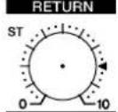 | ||
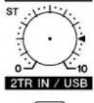 | ||||||||
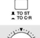 | ||||||||
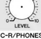 | ST | |||||||
| 1 | 2 | 3/4 | 5/6 | 7/8 | 9/10 | ST | ||
Yamaha Web Site (English only)
http://www.yamahasynth.com/
Yamaha Manual Library
- IMPORTANT NOTICE FOR THE UNITED KINGDOM
- Connecting the Plug and Cord
- COMPLIANCE INFORMATION STATEMENT (DECLARATION OF CONFORMITY PROCEDURE)
- FCC INFORMATION (U.S.A.)
- PRECAUTIONS
- PLEASE READ CAREFULLY BEFORE PROCEEDING
- WARNING
- Power supply/Power cord
- Do not open
- Water warning
- If you notice any abnormality
- CAUTION
- Location
- Connections
- Handling caution
- SPECIAL NOTICES
- Foreword
- Features
- Connect To Your Computer via a Single USB Cable (page 7)
- No Driver Installation Required (page 7)
- Cubase LE DAW Software Supplied (page 7)
- 3-Band EQ On Each Channel (page 15)
- Mixer Functions (page 15)
- 48V Phantom Power (page 16)
- Contents
- Foreword 5
- Quick Guide 7
- Front & Rear Panels 15
- Setting Up 20
- Troubleshooting 21
- Appendix 23
- SOFTWARE LICENSE AGREEMENT ..... 27
- Before Turning on the Mixer
- Be sure that the mixer's power switch is in the STANDBY position.
- Connect the power adaptor to the AC ADAPTOR IN connector (1) on the rear of the mixer, and then turn the fastening ring clockwise (2) to secure the connection.
- Plug the power adaptor into a standard household power outlet.
- Turning the Power On/OFF
- NOTE
- Computer System Requirements
- Cubase LE System Requirements
- Quick Guide
- Installing Cubase LE
- Follow the on-screen instructions to install the Cubase LE software.
- Connections
- Connect the MW10 to the Computer.
- USB Connection Precautions
- Connecting Microphones and/or Instruments.
- Balanced Cables and Unbalanced Cables
- Cable Guidelines
- Connector Types
- XLR Connectors
- Phone Connectors
- RCA Pin Connectors
- Powering Up the System
- Adjusting Level and Equalization
- Level Adjustment
- EQ Adjustment
- Use the High-pass Filter for Microphone Input
- Equalizer Tips
- Recording with Cubase LE
- Cubase LE Setup
- To prevent the playback sound from Cubase LE from being directly re-recorded, press the MW10 2TR IN/USB (ST/TO C-R) switch so that it's in the on (TO C-R) position.
- Launch Cubase LE.
- Windows:
- Macintosh:
- Select [Device Setup] from the [Devices] menu to open the Device Setup window.
- On a Windows computer click [Control Panel] in the Device Setup window. The ASIO Multimedia Setup dialog window will appear. Click [Advanced Options].
- Preparing to Record
- Use the [Stereo Switch] buttons in the Inspector to select stereo or monaural operation for the track: (☐) for stereo operation and (☐) for monaural.
- Select [Mixer] from the [Devices] menu to open the mixer window.
- Make sure that the [Record Enable] button (●) on the left side of the channel strip on.
- Play the instrument to be recorded and, while watching the mixer window level meter, adjust the MW10 GAIN controls, Channel LEVEL Controls, and ST Master LEVEL Control so that the meter never goes above 0.0 dB.
- Specify the point at which you want to start recording via the ruler at the top of the project window.
- Open the [Transport] menu and turn [Start Record at Left Locator] off.
- isRecording and Playback
- Click the Transport panel [Record] button to begin recording.
- Play the part.
- When you have finished recording the track, click the Transport panel [Stop] button.
- Mixing with Cubase LE
- Start with the Featured Part
- Pan Effectively
- At this point you can begin to use EQ to refine your mix, and add effects.
- When the final adjustments have been made to the mix, go to the [File] menu and select [Export] → [Audio Mixdown].
- Enter a file name and select a file type.
- Click [Save].
- Front & Rear Panels
- Channel Control Section
- ①GAIN Control
- ②PEAK Indicator
- ③ Switch (High Pass Filter)
- ④ Equalizer (HIGH, MID, and LOW)
- ⑤AUX Controls
- ⑥PAN Control (CHs 1 and 2) PAN/BAL Control (CHs 3/4 and 5/6) BAL Control (CHs 7/8, 9/10)
- ⑦Channel LEVEL Control
- Master Control Section
- ①PHANTOM +48 V Switch
- ②RETURN Control
- ③2TR IN/USB Control
- ④2TR IN/USB Switch (TO ST/TO C-R)
- ⑤ST Master LEVEL Control
- ⑥C-R/PHONES LEVEL Control
- ⑦Level Meter
- POWER Indicator
- Input/Output Section
- ①Channel Input Jacks (CHs 1, 2, 3/4, 5/6)
- ② INSERT I/O Jacks (CHs 1 and 2)
- ③Channel Input Jacks (CHs 7/8, 9/10)
- ④2TR IN Jacks
- ⑤REC OUT (L, R) Jacks
- ⑥ST OUT (L, R) Jacks
- ⑦C-R OUT Jacks
- 8SEND Jacks
- • A UX1, AUX2
- ⑨RETURN L (MONO), R Jacks
- 10PHONES Jack
- Rear Section
- ①AC ADAPTOR IN Connector
- ②POWER Switch
- ③USB Connector
- Setting Up
- Setup Procedure
- Setup Examples
- Troubleshooting
- The MW10 mixer won't turn on.
- The system doesn't work properly.
- No sound.
- The recorded sound is too low in level.
- The sound is intermittent or distorted.
- There is a delay when playing a software synthesizer via a MIDI keyboard (latency).
- Appendix
- Specifications
- Dimensional Diagrams
- Block Diagram and Level Diagram
- ATTENTION
- SOFTWARE LICENSE AGREEMENT
- GRANT OF LICENSE AND COPYRIGHT
- RESTRICTIONS
- TERMINATION
- LIMITED WARRANTY ON MEDIA
- DISCLAIMER OF WARRANTY ON SOFTWARE
- LIMITATION OF LIABILITY
- THIRD PARTY SOFTWARE
- GENERAL
- COMPLETE AGREEMENT
- ACHTUNG
- BESCHRÄNKTE GARANTIE AUF DIE SOFTWARE
- U.S.A.
- CENTRAL & SOUTH AMERICA
- MEXICO
- PANAMA AND OTHER LATIN
- AMERICAN COUNTRIES/
- CARIBBEAN COUNTRIES
- IRELAND
- GERMANY
- POLAND
- SWEDEN
- DENMARK
- FINLAND
- NORWAY
- OTHER EUROPEAN COUNTRIES
- AFRICA
- MIDDLE EAST
- TURKEY/CYPRUS
- OTHER COUNTRIES
- ASIA
- THE PEOPLE'S REPUBLIC OF CHINA
- HONG KONG
- INDONESIA
- KOREA
- MALAYSIA
- PHILIPPINES
- SINGAPORE
- 03-11 A-Z Building
- TAIWAN
- THAILAND
- OTHER ASIAN COUNTRIES
- OCEANIA
- AUSTRALIA
- NEW ZEALAND
- COUNTRIES AND TRUST
- TERRITORIES IN PACIFIC OCEAN
Brand : YAMAHA
Model : MW10
Category : DJ Equipment