GEM45 - Tripod iOptron - Free user manual and instructions
Find the device manual for free GEM45 iOptron in PDF.


| Product Type | German Equatorial Mount (GEM) with LiteRoc Tripod |
| Model Numbers | GEM45 (#7603A), GEM45EC (#7603ECA), GEM45G (#7603AG) |
| Maximum Payload | 45 lbs (20 kg), excluding counterweight |
| Mount Weight | 17.5 lbs (7.9 kg) |
| Tripod Weight | Approximately 17.6 lbs (8 kg) (LiteRoc 1.75" Stainless Steel) |
| Latitude Adjustment Range | 14° to 68° |
| Azimuth Adjustment Range | ±6° |
| Right Ascension Worm Wheel | Φ110 mm, 216 teeth aluminum |
| Declination Worm Wheel | Φ110 mm, 216 teeth aluminum |
| Periodic Error Correction (PEC) | PPEC (GEM45/GEM45G) or Real-time PEC (GEM45EC); PE <±7 arcsec p-p (GEM45/GEM45G), <0.25 arcsec RMS (GEM45EC) |
| Motor Drive | Precision stepper motor, 1.8°/128X micro-step, 0.08 arcsec resolution |
| Slew Speeds | 1×, 2×, 8×, 16×, 64×, 128×, 256×, 512×, MAX (~4.5°/sec) |
| Tracking Rates | Sidereal, Solar, Lunar, King, Custom (0.9900× to 1.0100× sidereal) |
| Power Requirement | 12V DC 5A (AC adapter 100-240V included) |
| Power Consumption | 0.6A (tracking), 0.9A (GOTO) |
| Hand Controller | Go2Nova® 8407+, 212,000+ object database, star identification, heated LCD |
| Polar Alignment | Built-in iPolar™ electronic polar scope; also supports polar iterate align and drift alignment |
| Guiding (GEM45G) | Built-in iGuider™ guiding scope (30mm aperture, 120mm focal length) and camera |
| Dovetail Saddle | 6" dual saddle compatible with Losmandy D and Vixen-style plates |
| Communication Ports | USB 2.0 (on mount), ST-4 autoguide port, HBX (hand controller), iPORT (accessories) |
| GPS | External 32-channel GPS module |
| WiFi | Optional iStarFi adapter (#7434) |
| Operating Temperature | -10°C to +40°C |
| Warranty | Two-year limited warranty (USA and Canada) |
Frequently Asked Questions - GEM45 iOptron
User questions about GEM45 iOptron
0 question about this device. Answer the ones you know or ask your own.
Ask a new question about this device
Download the instructions for your Tripod in PDF format for free! Find your manual GEM45 - iOptron and take your electronic device back in hand. On this page are published all the documents necessary for the use of your device. GEM45 by iOptron.
USER MANUAL GEM45 iOptron
natural_image
Close-up of a black and red GEMAS instrument tripod with adjustable arms and a metallic handle (no visible text or symbols)iOptron® GEM45 German Equatorial Mount Instruction Manual
Product GEM45 (#7603A), GEM45EC (#7603ECA) and GEM45G (#7603AG)

Please read the included GEM45 Quick Setup Guide (QSG) BEFORE taking the mount out of the case!
This product is a precision instrument. Please read the included QSG before assembling the mount. Please read the entire Instruction Manual before operating the mount.
You must hold the mount firmly when disengaging the gear switches. Otherwise personal injury and/or equipment damage may occur. Any worm system damage due to improper operation will not be covered by iOptron's limited warranty.
If you have any questions please contact us at support@ioptron.com

WARNING!
NEVER USE A TELESCOPE TO LOOK AT THE SUN WITHOUT A PROPER FILTER! Looking at or near the Sun will cause instant and irreversible damage to your eye. Children should always have adult supervision while using a telescope.
Table of Contents
Table of Contents 3
- GEM45 Introduction .... 5
- GEM45 Overview ...... 6
2.1. Parts List....6
2.2. Identification of Parts 7
2.3.GEM45Mount Basic Cable Connection 7
2.3.1. Power Panel on Rear of RA axis 7
2.3.2. Ports on Main Control Board 8
2.3.3. Ports on Dovetail Saddle 8
2.4.Go2Nova® 8407+ Hand Controller....10
2.4.1.Key Description....10
2.4.2. The LCD Screen....11
2.4.3. Check the Hand Controller Battery 12
2.5.Bench Testing the Mount 12
- GEM45 Mount Assembly....13
3.1. GEM45 Mount Assembly....13
- Getting Started....21
4.1. Setting the Mount and Performing Polar Alignment....21
4.2. Manual Operation of the Mount 21
4.3. One Star Alignment....21
4.4. GOTO the Moon and Other Objects .....21
4.5. Star Identification Function 21
4.6. Power-Down Memorization 22
4.7. Turning Off the Mount 22
4.8. Putting the Mount Back into the Carrying Case....22
- Complete Functions of Go2Nova ^ 8407+ Hand Controller ....23
5.1. Select and Slew....23
5.1.1. Solar System....23
5.1.2. Deep Sky Objects 23
5.1.3. Stars 23
5.1.4.Comets 23
5.1.5. Asteroids....23
5.1.6. Constellations 23
5.1.7.Custom Objects 23
5.1.8.Custom R.A.and DEC 24
5.2. Sync to Target....24
5.3. Alignment 24
5.3.1. Position of Polaris/SigmaOct 24
5.3.2. One Star Alignment....24
5.3.3. Two Star Alignment 24
5.3.4. Three Star Alignment 25
5.3.5. Solar System Align....25
5.3.6. Polar Iterate Align 25
5.3.7.View Model Error....25
5.3.8. Clear Alignment Data....25
5.4. Settings 25
5.4.1. Set Time and Site....25
5.4.2. Beep Settings....26
5.4.3. Display Settings....26
5.4.4. Set Guiding Rate....26
5.4.5. Set Tracking Rate 27
5.4.6. Set Parking Position 27
5.4.7. Meridian Treatment 27
5.4.8. Set Altitude Limit 27
5.4.9. Polar Scope Bright....27
5.4.10. HC Heating Switch....27
5.4.11. Set RA Guiding 28
5.4.12. Language 28
5.5. Electric Focuser 28
5.6.PEC Option 28
5.6.1. PEC Playback 28
5.6.2. Record PEC 28
5.6.3. PEC Data Integrity 28
5.7. Park Telescope....29
5.8. Edit User Objects....29
5.8.1.Enter a New Comet 29
5.8.2. Enter Other Objects or Observation List....29
5.9. Firmware Information ...... 30
- Maintenance and Servicing .... 31
6.1. Maintenance .... 31
6.2.iOptron Customer Service 31
6.3. Product End of Life Disposal Instructions .... 31
6.4. Battery Replacement and Disposal Instructions....31
Appendix A. Technical Specifications 32
Appendix B. Go2Nova ^® 8407+ HC MENU STRUCTURE ....33
Appendix C. Go2Nova ^® Star List .... 36
Appendix D. Gear Meshing Adjustment 45
Appendix E. Polar Alignment using iPolar Electronic PolarScope ....47
Appendix F. iGuider for GEM45G 48
Appendix G. Firmware Upgrade 53
Appendix H. Computer Control a GEM45 Mount....54
IOPTRON TWO YEAR TELESCOPE, MOUNT, AND CONTROLLER WARRANTY....55
1. GEM45 Introduction
Innovative ideas applied to a time tested design, the iOptron ^ GEM45 next generation German equatorial mounts. A sharp looking CNC body is the first indicator the GEM45 is a top quality mount in both form and function.
Utilizing experiences gained during development of our CEM series, we were able to remove unnecessary bulk giving the GEM45 an incredible 2.5 payload to mount weight ratio. This compact 17.4lbs mount can precisely GOTO an object and track with up to 45lbs of gear onboard.
With its integrated electronic polar scope (iPolar ^TM ), polar alignment is a snap, even when the pole star is obscured. Large levers on the quick-lock drive engagement system make it easy to snap its drive gears into place even when wearing gloves. There is little chance of your cables getting snagged with the GEM45's internal advanced cable management system.
Make way for an innovative mount! The GEM45G mount has a built-in iGuider™ guiding camera. The mount has a 6" dual saddle that accommodates Losmandy and Vixen-style dovetail plates. GEM45 mounts utilize reliable stepper motor drive systems with our low power consumption technology. Our new LiteRoc 1.75" tripod delivers rock solid stability in a lighter, more compact package. A 212,000+ object library with star identification, GPS, Wi-Fi (requires optional iStarFi adapter) are a few of the desirable features standard on a GEM45 mount.
Features:
• German equatorial mount with innovative features
- Idea for both visual observation and astrophotography
• Maximum payload of 45 lbs (20 kg) with the mount weight of only 17.4 lbs (7.9 kg)
- Easy to use quick-lock gear clutches
- Integrated iPolar ^TM electronic polar finder
• Built-in iGuider ^TM guiding camera for GEM45G
- Low periodic error: < ± 7 arc seconds for GEM45 and GEM45G, < 0.25 arcsec RMS for GEM45EC
• Permanent periodic error correction (PPEC) or Real-time periodic error correction (for GEM45EC)
- Precision stepper motor for precise GOTO and accurate tracking
- Go2Nova ^ 8407+ controller with Advanced GOTONOVA ^ GOTO Technology and built-in heater
- Integrated ST-4 autoguiding port
• 32-channel Global Positioning System (GPS)
- USB communication port
- Cable management system
- All metal, CNC machined with red/black anodized
- Optional WiFi module (iStarFi, #7434) for mount control via SmartPhone/Tablet/Computer
- All new LiteRoc 1.75" tripod with improved stability and leg locks
2. GEM45 Overview
2.1. Parts List ^1
SHIPPING CONTENTS
Your new GEM45 mount comes in three shipping boxes. Box 1 contains either a GEM45 (#7620A), a GEM45G (#7620AG) or GEM45EC (#7620ECA) mount head, hand controller, counterweight shaft, and accessories. Box 2 contains the LiteRoc tripod (#7623). Box 3 is a 11lbs (5kg) counterweight (#8027).
The contents are:
- iOptron ^ GEM45 telescope mount
- GEM45 with iPolar ^TM electronic Polar Scope (#7620A);
- GEM45EC with iPolar and High Precision Optical Encoder (#7620ECA); or
- GEM45G with iPolar and iGuider ^TM guiding system (#7620AG)
- Go2Nova ^ 8407+ Hand Controller
• One 11lbs (5 kg) counterweight (#8027)
• Stainless steel counterweight shaft
- Internal iPolar electronic polar scope
• Built-in iGuider autoguiding system on dovetail saddle (GEM45G only)
• GEM45 GPS module
• AC adapter (100V-240V)
- 2X coiled control Cable (6P6C RJ11 to RJ11, straight wired)
- USB cable
• Aluminum carrying case (for GEM45EC & GEM45G)
- LiteRoc 1.75" tripod and accessory tray
- Quick Start Guide
OPTIONAL PARTS
- Tri-Pier (#8034)
• iStarFi wireless adapter (#7434) - Serial cable for 8407 hand controller firmware upgrade (#8412)
ONLINE RESOURCES (click on the "Support" menu at www.iOptron.com)
- Quick Start Guide
- Instructional manual
- Tips for set up
- Hand controller and mount firmware upgrades (check online for latest version)
- iOptron ASCOM driver
• Reviews and feedback from other customers - Accessories
2.2. Identification of Parts
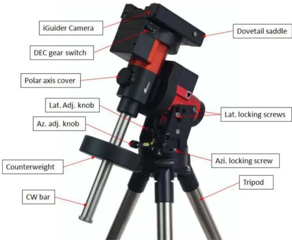
Figure 1. GEM45 mount assembly (GEM45G Shown)
2.3. GEM45 Mount Basic Cable Connection
2.3.1. Power Panel on Rear of RA axis
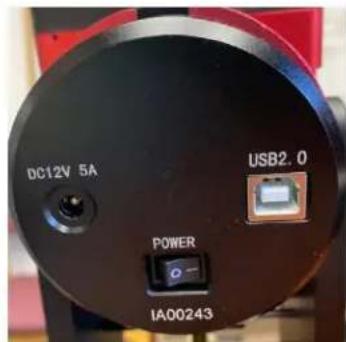
Figure 2. GEM45 Power Panel on Rear of RA axis
• POWER (I/O): Power Switch
- DC 12V 5A: DC power socket to power the mount (2.5mm×5.5mm, center positive)
- USB2.0: USB input port to connect to iPolar, iGuider, USB 2.0 Port on dovetail saddle, as well as mount computer control and firmware upgrade.
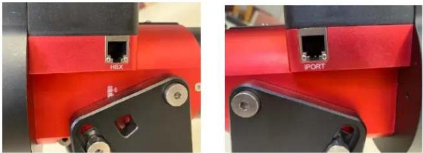
2.3.2. Ports on Main Control Board
natural_image
Close-up of two red industrial machinery components with labeled ports (HBX and iPORT), no readable text or symbols beyond labels.Figure 3. Ports on a GEM45 main board
• HBX (Hand Box): For connecting to an 8407 Hand Controller
- iPORT: Auxiliary port for connecting to other iOptron accessories, such as a GPS receiver, an iStarFi WiFi adapter, an electronic focuser or for observatory dome control. DO NOT plug ST-4 guiding camera cable into this port. It will damage the guide camera electronics.
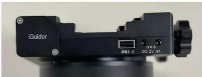
2.3.3. Ports on Dovetail Saddle
On the back of the dovetail saddle, there are one USB2.0 port and two DC 12V outputs.
natural_image
Close-up of a black iGuider camera with visible ports and control knob (no text or symbols on body)Figure 4. Port on back of the dovetail saddle (a GEM45G shown)
- 1X USB 2.0 ports with standard type A connectors for connecting accessory;
- 2X DC12V power outlet (2.1mm×5.5mm, center positive, max. current 3A) for powering accessories such as CCD cameras, filter wheels, or electric focusers;
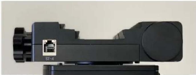
The ST-4 guiding port is located in front of the dovetail saddle.
natural_image
Close-up of a black electronic device with an internal port labeled 'ST-4' and a connector icon (no readable text beyond label)Figure 5. Port on front of the dovetail saddle
- ST-4: ST-4 compatible autoguiding port. The wiring is shown in Error! Reference source not ound.
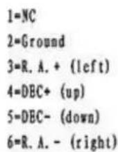
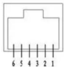
Figure 6. ST-4 Compatible Guiding Port Wiring
2.4. Go2Nova ^® 8407+ Hand Controller
The Go2Nova ^® 8407+ hand controller (HC) shown in Figure 7 is the standard controller used on the GEM45 mount. It has an integrated heater that ensures the LCD display will work at the temperature as low as -10°C. It has a large LCD screen, function, direction, and number keys on the front; a red LED reading light on the back; and a HBX (6-pin) and a RS232 serial port (4-pin) at the bottom.
The GEM45 mount can be operated without the hand controller attached if it is controlled via a SmartPhone/Tablet/Computer.
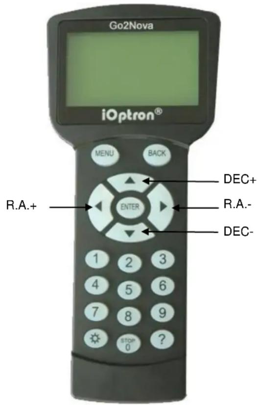
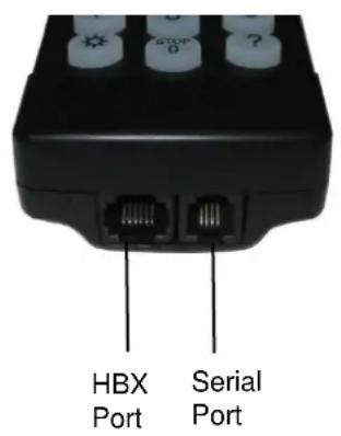
Figure 7. Go2Nova ^® 8407+ hand controller
2.4.1. Key Description
- MENU Key: Press "MENU" to enter the Main Menu.
- BACK Key: Move back to the previous screen, or end/cancel current operation, such as slewing.
- ENTER Key: Confirm an input, go to the next menu, select a choice, or slew the telescope to a selected object.
- Arrow (▲▼◀▶) Keys: The arrow keys are used to control the movement of DEC and R.A. axes. Press and hold ▲(DEC+),▼(DEC-) buttons to move a telescope along the DEC direction, ◀(R.A.+), ▶(R.A.-) to move a telescope along the R.A. direction. They are also used to browse the menu or move the cursor while in the menu. Press and holding an arrow key for a fast scrolling.
- Number Keys: Input numerical values. Also used to adjust speeds (1: 1X; 2: 2X; 3: 8X; 4: 16X; 5: 64X; 6: 128X; 7: 256X; 8: 512X; 9: MAX)
• Light Key(☐): Turns on/off the red LED reading light on the back of the controller. - Help (?) Key: Identify and display bright stars or objects that the telescope is pointing to.
-
STOP/0 Key: Stop the mount during GOTO. Also toggling between starting and stopping tracking.
-
HBX (Handbox) port: connect the HC to the GEM45 mount using a 6P6C RJ11 cable.
- Serial port: connect the HC to a computer via a RS232 to 4P4C RJ9 cable. The pin-out of the serial port is shown in Figure 8.
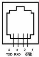
Figure 8. Serial port pin-out on an 8407+ hand controller
2.4.2. The LCD Screen
The 8407+ HC has a large 8-line, 21-character per line, LCD screen which displays information on the status of the mount as shown in Figure 9. The user interface is simple and easy to operate.

Figure 9. 8407+ HC LCD Information Screen
-
Target Name/Mount Position: displays the name of the target that telescope is currently pointed to or the current mount position.
-
Zero Position: The reference position for GOTO. The mount can move to Zero Position using "Goto Zero Position" or "Search Zero Position" command;
- User Position: The mount is pointed to a user defined position, which could be a particular celestial object or simply a position determined by pressing an arrow key;
-
An object name, such as "Mercury" or "Andromeda Galaxy": Name of the star or celestial object that the mount is currently slewing to or tracking.
-
Target R.A.: Right Ascension (R.A.) of the target object.
- Target Declination: Declination (DEC) of the target object.
- Right Ascension: Current R.A. of the telescope.
- Declination: Current DEC of the telescope.
- Altitude: Altitude of the telescope (degrees vertical from the local horizon - zenith is 90°).
- Azimuth: Azimuth of the telescope (north is 0^ , east is 90^ , south is 180^ , and west is 270^ ).
- Local Date and Time: displays the local time in a format of YY-MM-DD HH:MM:SS.
-
Mount Status: Displays the current operational status of the mount.
-
Stop: mount is not moving;
- Slew: mount is moving with an arrow key is pressed or a GOTO command, such as "Select and Slew" or "Goto Zero Position";
-
Tracking: mount is at a tracking status.
-
GPS status: When the power is turned on, the initial GPS status will be "GPS ON", which means that the mount is connected to its GPS receiver and is seeking a satellite signal. When the GPS receiver finds the satellites and receives the GPS signal the status will change to "GPS OK".
-
PEC status: Display of "PEC" here Indicates the Periodic Error Correction playback is turned on. Default is off.
-
Tracking speed: Displays the current tracking rate of the mount.
-
SDRL: mount is tracking at sidereal speed;
• Solar: mount is tracking at solar speed; - Lunar: mount is tracking at lunar speed;
• King: mount is tracking at king speed; -
CSTM: mount is tracking at a custom, user-defined speed.
-
Slew speed: The mount has 9 slew speeds: 1X, 2X, 8X, 16X, 64X, 128X, 256X, 512X, MAX ( 4°/sec).
-
Operation Mode: EQ indicates that the mount is operating in an equatorial mode.
2.4.3. Check the Hand Controller Battery
The hand controller has a real time clock (RTC) which should display the correct time every time the mount is turned on. If the HC can't keep the date and time, the battery is low and needs be replaced. Please open the back cover of the HC and replacement is straight forward.
2.5. Bench Testing the Mount
The counterweight shaft is designed to counter balance the mount's own weight. It is recommended that the CW shaft is installed when testing the mount's function. Slewing the mount without the CW shaft installed is not recommended.
NEVER operate the mount with only the counterweight or OTA on it. It may damage the precision engineering of the mount drive system.
3. GEM45 Mount Assembly
3.1. GEM45 Mount Assembly
NOTE: The GEM45 mount is a precision astronomical instrument. It is highly recommended that you read this entire manual and become familiar with the nomenclature and function of all components before starting assembly.

WARNING: DO NOT rock the counterweight shaft rigorously. This may damage the worm/drive gear system and such damage will not be covered by warranty.
STEP 1. Remove the mount head from package
The mount head is shipped with the R.A. Gear Switch unlocked to protect the worm/gear system. Turn the Gear Switch 90° to lock the R.A. gear system before removing it from the box.
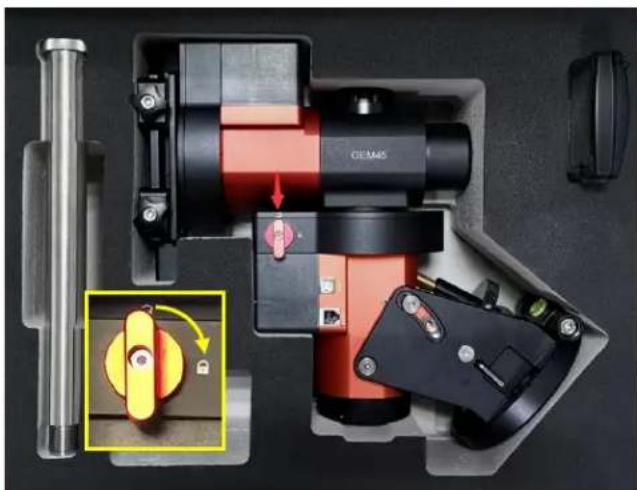
natural_image
Interior view of a mechanical device with red and black components, showing a close-up of a yellow rotary knob (no text or symbols visible)Figure 10. Mount in a hard case
STEP 2. Set up tripod
The tripod top is 120 mm in diameter with 2x M6 holes 103 mm apart for mounting. Two additional M6 holes are for the Alignment Peg (the one on top of a leg is for high latitude use; the other one between two legs is for low latitudes). Thread the Alignment Peg into the correct M6 hole. Insert the Accessory Tray through the center rod and secure the setup by tightening Locking Knob from underneath.
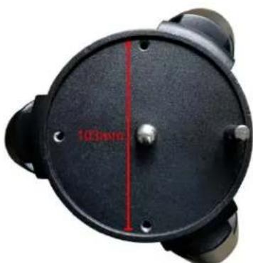
Figure 11. Tripod top
STEP 3. Attach the mount
Retract the 2x Azimuth (Azi) Adjustment Screws from both sides to leave ample space for the alignment peg to fit in between the 2 Azi Adjustment Screws. Remove the 2x Azi Locking Screws, with washers, from the mount base. Secure the mount head by tightening the Azi Locking Screws into the M6 holes on the tripod. An Allen wrench is included for convenience.
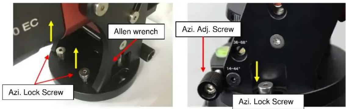
Figure 12. Attach the mount
Level the mount by adjusting the tripod legs. Use the build-in Bubble Level Indicator or an external leveler for this purpose.
Without any payload, slightly loosen the 4x Latitude Locking Screws. Use the Latitude Adjustment Knob to set the correct latitude value, as displayed in the Latitude Mark Window. Insert the Allen wrench into the Latitude Adjustment Knob for more turning torque.
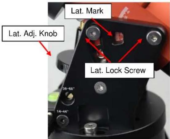
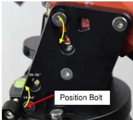
Two latitude ranges, 14\~44° and 36\~68°, can be set up for the mount head. To change the latitude range from one to the other, both the Latitude Position Bolt and the Latitude Locking Screws need to be moved to the correct locations (see photos below).
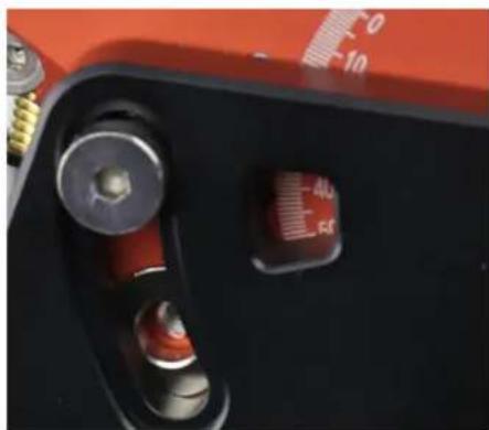
Loosen the Latitude Locking Screws just enough to adjust the latitude setting to 40^ . Move the Latitude Locking Screws with washers (one on each side) to the new locations revealed, do not tighten them just yet.
natural_image
Close-up of a red and black electronic device with a red indicator light and screw ports (no readable text or symbols)Figure 14. Latitude mark window
Unthread and remove the Position Bolt to its new location. Adjust the Latitude Adjustment Knob while holding the brass eyebolt until it lines up with the Position Bolt. Secure the Latitude Position Bolt.
STEP 5. Install Counterweight (CW) Shaft
Thread the CW shaft into the CW shaft mounting holes.
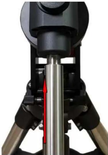
natural_image
Close-up of a mechanical device with a metallic cylindrical component inserted, showing a red arrow indicating motion direction (no text or symbols visible)Figure 16. Install CW shaft
STEP 6. Install Counterweight(s)
Before putting on CW, make sure the mount is at its zero position, i.e., CW shaft points to the ground. Disengage the R.A. Gear Switch to set the R.A. axis free before loading the CW. Remove the CW Safety Cap at the end of CW Shaft. Glide the CW over the shaft. Tighten the CW Locking Screw to hold the CW in place. Place the Safety Cap back onto the shaft. Move the CW to the bottom of the shaft and tighten the CW locking Screw.
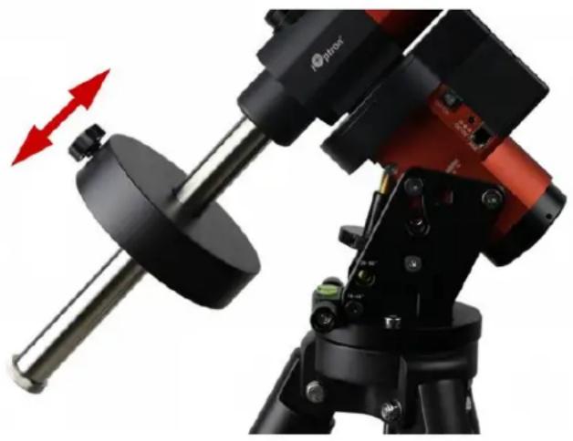
natural_image
Close-up of a black optical instrument with red components and a red directional arrow indicating rotation (no text or symbols visible)Figure 17. Install Counterweight
You may need more CW for heavier payloads, or a smaller CW for lighter scopes.
GEM45 is equipped with a Vixen/Losmandy-D dual saddle. It can receive either a Vixen or a Losmandy-D plate. Release the dovetail saddle locking knobs and slide the telescope dovetail plate into the saddle. Tighten the saddle locking knobs.
STEP 7. Balance the Payload
After attaching the scope and accessories, the mount head assembly must be balanced in both DEC and RA axes to ensure minimum stresses on the mount driving mechanism.

CAUTION: The telescope may swing freely when the R.A. or DEC Gear Switch is disengaged. Always hold on to the mount and/or telescope assembly before releasing the Gear Switches to prevent it from swinging, which can cause personal injuries and/or equipment damages.
Set the mount at Zero Position. Disengage both RA and DEC gear switches and move the mount to horizontal position to check balance. Return to Zero Position for balance adjustment. Balance the DEC axis by moving the scope with accessories back and forth in the mount saddle or within the scope mounting rings. Balance the assembly in R.A. axis by moving CW along its shaft. Repeat the process until both DEC and RA axes are balanced.
CAUTION: The balancing process MUST be done with Gear Switch at the total disengaged position! Otherwise it might damage the worm system.
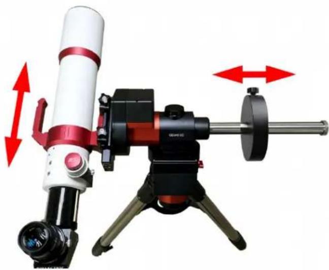
natural_image
Close-up of a telescope with red and white components mounted on a tripod, showing alignment arrows (no text or symbols visible)Figure 18. Balance a mount
Return the mount to Zero Position after balancing and engage gear switches.
STEP 8. Connect Cables
Plug in included 12V/5A DC power supply to the DC12V 5A socket, which is located at the end of the RA axis.
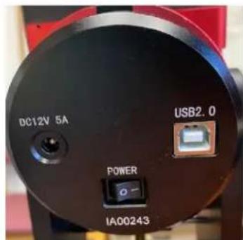
Figure 19. Power connection
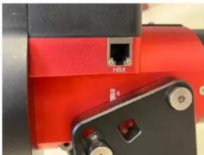
Connect the Go2Nova® 8407 Hand Controller to the HBX port on the mount main board. Plug GPS module into the iPORT with a coiled cable. When powering on, GPS ON sign should be displayed at the upper right corner of the hand controller.
natural_image
Close-up of a red industrial machine component with black and red parts, no visible text or symbols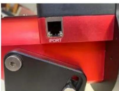
natural_image
Close-up of a red and black mechanical device with an iPORT terminal labeled (no readable text beyond label)Figure 20. Ports for cables
If you want to use the iPort for another accessory, such as WIFI adapter (iStarFi #7434), or electronic focuser (#8451/#8452), you may disconnect the GPS module after it picks up satellites signals and displays GPS OK on hand controller. (It takes about 1 to 2 minutes in normal conditions).
STEP 9. Setting up the Hand Controller
The GEM45 mount is equipped with a GPS receiver which will receive the time, longitude and latitude information for your current location from satellites after a link is established. However, there are still some parameters which need to be entered to reflect your location, such as time zone information and whether daylight saving time is currently in effect. This information will be stored in the hand controller memory along with longitude and latitude coordinates until they need to be updated.
A clear sky and open space outside is needed for the GPS to establish a link with the satellites.
To set up the controller, press MENU => "Settings":
Select and Slew
Sync. to Target
Alignment
Settings
Electric Focuser
PEC Options
Park Telescope
Edit User Objects
Press ENTER and select "Set Time and Site"
Set Time and Site
Beep Settings
Display Settings
Set Guiding Rate
Set Tracking Rate
Set Parking Position
Meridian Treatment
Set Altitude Limit
Press ENTER. A time and site information screen will be displayed:
Daylight Saving Time Y
UTC -300 Minute(s)
2019-03-09 10:19:18
Longitude:W071d08m50s
Latitude: N42d30m32s
Northern Hemisphere
Set Local Time
The time will be updated automatically when the GPS receiver has established its link to the satellites. In the event that the GPS module is unable to establish a link, local time can be entered manually. Use the ◀ or ▶ key to move the cursor and use the number keys to change the numbers. Use the ▲ or ▼ button to toggle between "Y" and "N" for Daylight Saving Time, or "+" and "-" for UTC (Coordinated Universal Time) setting. Hold the arrow key to fast forward or rewind the cursor.
In order to make the Hand Controller reflect your correct local time, time zone information has to be entered. Press the ◀ or ▶ key, move the cursor to the third line "UTC -300 Minute(s)" to set the time zone information (add or subtract 60 minutes per time zone). For example:
• Boston is "UTC -300 minutes"
• Los Angeles is "UTC -480 minutes"
- Rome is "UTC +60 minutes"
- Beijing is "UTC +480 minutes"
• Sydney is "UTC +600 minutes"
All the time zones in North America are "UTC –", as shown in the following table, so ensure the display shows "UTC -" instead of "UTC +".
| Time Zone | Hawaii | Alaska | Pacific | Mountain | Central | Eastern |
| Hour behind UT | -10 | -9 | -8 | -7 | -6 | -5 |
| Enter UTC | -600 | -540 | -480 | -420 | -360 | -300 |
To adjust minutes, move the cursor to each digit and use the number keys to input the number directly. Use ▲ or ▼ key to toggle between “+” and “-”. When the time one information entered is correct, press ENTER and go back to the previous screen. Note that fractional time zones can be entered.
Do not manually add or subtract an hour from displayed time to reflect Daylight Saving Time (DST). Only select "Y" after DST begins.
For other parts of the world you can find your “time zone” information from internet.
Set Observation Site Coordinates
The fifth and sixth lines display the longitude and latitude coordinates, respectively. The longitude and latitude coordinates will be automatically updated when the GPS picks up a satellite signal. "W/E" means Western/Eastern Hemisphere; "N/S" means Northern/Southern Hemisphere; "d" means degree; "m" means minute; and "s" means second.
If, for any reason, your GPS does not pick up the satellite signal, you can manually enter your longitude and latitude coordinates. Press the ◀ or ▶ key to move the cursor, use the ▲ or ▼ key to toggle between "W" and "E", and "N" and "S", and use the number keys to change the numbers. It is always a good idea to do your homework and get longitude and latitude coordinates before traveling to a new observation site.
The site coordinates information can be found from your smart phone, GPS receiver or via the internet. Site information in decimal format can be converted into d:m:s format by multiplying the decimal numbers by 60. For example, N47.53 can be changed to N47°31'48": 47.53^ = 47^ + 0.53^ , 0.53^ = 0.53 × 60' = 31.8' , 0.8' = 0.8 × 60'' = 48'' . Therefore, 47.53^ = 47^31'48'' or 47d31m48s.
Check the Hand Controller Battery
The hand controller has a real time clock (RTC) which should display the correct time every time the mount is turned on. If the time is incorrect, please check the battery inside the hand controller and replace it if required.
STEP 10. Set the Zero Position
Zero Position is the mount starting reference point which ensures the GOTO performance. Press MENU => "Zero Position" => "Search Zero Position" to let the mount search the Zero Position. Follow the instruction on hand controller display to adjust the Zero Position if RA or DEC is not aligned. Or press MENU => "Zero Position" => "Set Zero Position", to manually set the mount to Zero Position. Loosen the DEC and R.A. Gear Switches in turn to adjust the mount to the Zero Position. Engage the clutches after each adjustment.
STEP 11. Perform Polar Alignment
Polar Alignment with iPolar Electronic Polar Scope
GEM45 are equipped with an iPolar ^TM electronic polar scope. To perform polar alignment, please refer to Appendix C. It is simple and fast, even the pole star or part of the sky is blocked. Steps are briefly outlined below:
- Download and install iPolar Software (first time use)
- Connect a USB cable between the iPolar port on the mount and a computer USB port
- Calibrate the iPolar Rotation Center (first time use)
- Start polar alignment by following on screen instructions
BrightStar Polar Alignment
If you can't use the iPolar for some reason, you may use the drift alignment for precise polar alignment. Or may use two bright stars with Polar Iterate Align to do a polar alignment.
(1) Level the mount and set it to the Zero Position. Align the telescope to the R.A. axis of the mount. If a finder scope is used, adjust it to be parallel to the telescope optical axis.
(2) Use the HC (MENU => "Alignment" => "Polar Iterate Align") to display the azimuth and altitude position of several bright stars near the meridian. Select one that is visible at a high altitude as Alignment Star A. Follow the HC instruction to move Alignment Star A to the center of the eyepiece using a combination of the Latitude Adjustment Knob and the “◀” or “▶” buttons. Press ENTER to confirm when the star is centered. Next, select a bright star that is close to the horizon as Alignment Star B. Center it using the Azimuth Adjustment Knob and the “◀” or “▶” button (the “▲” and “▼” buttons are not used here). Press ENTER to confirm the settings.
(3) The telescope will now slew back to Alignment Star A. Repeat the steps above. The iteration can be stopped when it is determined that the alignment error has been minimized. Press the BACK button to exit the alignment procedure.
NOTE: It is highly recommended to use an eyepiece with an illuminated crosshair for accurate centering.
NOTE: The movement of the alignment star in your eyepiece may not be perpendicular depending on its location in the sky.
STEP 12. Returning the Mount to Zero Position
After polar alignment and balancing OTA, return the mount to the Zero Position. Please check the zero position after set up the mount or firmware update.
4. Getting Started
In order to experience the full GOTO capability of GOTONOVA® technology it is very important to set up the mount correctly before observation.
4.1. Setting the Mount and Performing Polar Alignment
Assemble your GEM45 mount according to Section 3.1. Make sure the mount is leveled. Turn the mount power switch on. When the GPS receiver is connected to satellites, the hand controller LCD will display GPS OK and the mount will have the correct time and site information (this can also be entered manually as previously described). Mount an OTA and accessories, and carefully balance the mount on both R.A. and DEC axes. Perform the polar alignment.
After the mount is powered on, perform MENU => "Zero Position" => "Goto Zero Position" to check the Zero Position, i.e. with the counterweight shaft pointing to ground, OTA at the highest position with its axis parallel to the polar axis and the telescope pointing to the Celestial Pole. If the mount is not at the Zero Position, you may perform Search Zero Position or Set Zero Position to set the Zero Position.
4.2. Manual Operation of the Mount
The mount can now be used to observe astronomical objects using the HC. Use the arrow keys (▶, ◀, ▼, and ▲) to point the telescope to the desired part of the sky. Use the number keys to change the slewing speed. Press the STOP/0 button to start tracking.
4.3. One Star Alignment
After the mount set up, perform a "One Star Align" to correct the Zero Position discrepancy, or linear error.
Press MENU => "Alignment" => "One Star Align" to perform "One Star Align." The hand controller will display an alignment star. Select a different star using the ▲ or ▼ keys. Then press ENTER. After the mount slews to the target, use the arrow keys to center it in your eyepiece. Then press ENTER. (More details on the alignment function are given in section 5.3)
4.4. GOTO the Moon and Other Objects
Now the mount is ready for GOTO operation which, using advanced GOTONOVA ^® technology, will automatically slew to, and track, a huge range of celestial targets. We will use the Moon as an example.
Press MENU => "Select and Slew". Select a category, in this example "Solar System", and then select an object of interest, in this case "Moon". Press ENTER and the telescope will slew to the moon and automatically start tracking. If the target is not centered in your eyepiece, use the arrow keys to center it.
Then use MENU => "Sync to Target" for better performance.
4.5. Star Identification Function
The 8407+ hand controller has a star identification function. After setting the correct local time and location and completing polar alignment, slew the telescope to a bright star manually or using the GOTO function. Press the Help(?) key to identify the star that the telescope is pointing to, as well as nearby bright stars if there is any.
4.6. Power-Down Memorization
The GEM45 mount can memorize its R.A. and DEC positions if the mount power is lost during operation, even during high speed slewing. After the power is back, just do a Select and Slew to the same star when the power is lost. The mount will continue to track the star.
4.7. Turning Off the Mount
When you have finished your observation, simply turn the mount power off and disassemble the mount and tripod.
If the mount is set up on a pier or inside an observatory, it is recommended that you return the mount to the Zero Position or park the telescope. This will ensure that there is no need for you to perform the initial setup again when you power on the mount subsequently so long as the mount has not been moved from the parked position.
4.8. Putting the Mount Back into the Carrying Case
It is recommended to disengage the gear system for transportation.
5. Complete Functions of Go2Nova ^® 8407+ Hand Controller
5.1. Select and Slew
Press the MENU button. From the main menu select "Select and Slew". Select an object that you would like to observe and press the ENTER key.
The Go2Nova ^® 8407+ hand controller has a database of around 212,000 objects. Use the ▶ or ◀ buttons to move the cursor. Use the number buttons to enter a number, or the ▼ or ▲ buttons to change a number. Hold a button to fast scroll through the list. The “◇”symbol indicates that the object is above the horizon, and the “◇” symbol means it is below the horizon. In some catalogs the stars below the horizon will not be displayed on the hand controller.
5.1.1. Solar System
There are 9 objects in the Solar System catalog.
5.1.2. Deep Sky Objects
This menu includes objects outside our Solar System such as galaxies, star clusters, quasars, and nebulae.
- Named Objects: consists of 92 popular deep sky objects with their common names. A list of named deep sky objects is included in Appendix C.
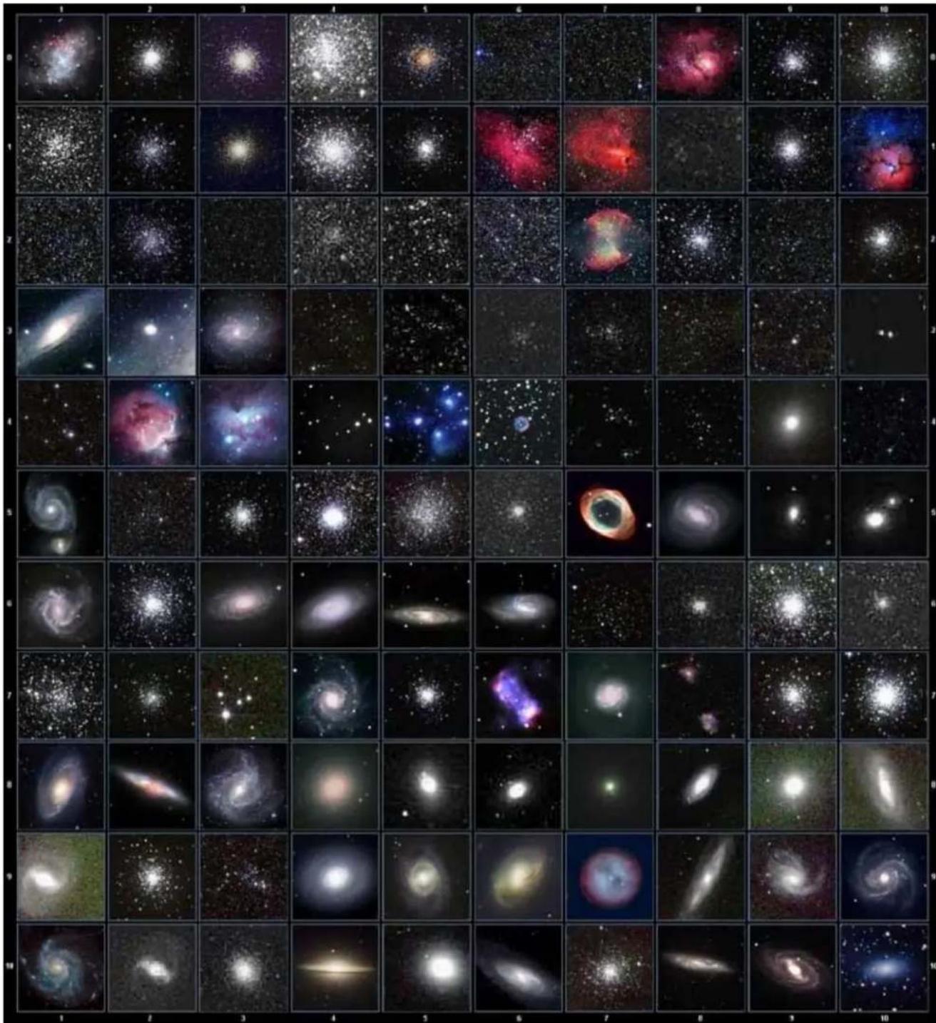
- Messier Catalog: consists of all 110 Messier objects.
• NGC Catalog: consists of 7,840 objects.
• IC Catalog: consists of 5,386 objects. - PGC Catalog: consists of 73,197 objects.
• Caldwell Catalog: consists of 109 objects. - Abell Catalog: consists of 4,076 objects.
• Herschel Catalog: consists of 400 objects.
5.1.3. Stars
- Named Stars: consists of 259 stars with their common names. They are listed alphabetically; a list is included in Appendix C.
- Double/Multi Stars: consists of 208 double/multi stars; a list is attached in Appendix C.
- Hipparcos Catalog: the new HIP catalog consists of 120,404 records (2008).
5.1.4. Comets
This catalog contains 15 comets.
5.1.5. Asteroids
This catalog contains 116 asteroids.
5.1.6. Constellations
This catalog consists of 88 modern constellations. They are listed alphabetically; a list is attached in Appendix C.
5.1.7. Custom Objects
This allows the storage of up to 60 user-defined objects, including comets.
5.1.8. Custom R.A. and DEC
Here you can go to a target by entering its R.A. and DEC coordinates.
5.2. Sync to Target
This operation will match the telescope's current coordinates to the Target Right Ascension and Declination. It can be used to correct GOTO pointing error. After slewing to an object, press MENU - then scroll to "Sync to Target" and press ENTER. Follow the screen to perform the sync. Using this function will re-align the telescope to the selected object. Multiple syncs can be performed if needed. This operation is useful to find a faint star or nebula near a bright star.
"Sync to Target" will only work after "Select and Slew" is performed. You can change the slew rate to make the centering procedure easier. Simply press a number (1 through 9) key to change the speed. The default slew rate is 64x.
5.3. Alignment
This function is used for aligning the telescope to the celestial pole and to create a sky model to calibrate the mount's GOTONOVA ^® functionality.
The system provides four alignment methods to calibrate the mount's GOTO function: "Solar System Align", "One Star Alignment", "Two Star Alignment" and "Three Star Alignment". The "Two Star Alignment" may be used to refine the polar alignment.
The mount has to be set to Zero Position before performing any alignment.
5.3.1. Position of Polaris/SigmaOct
This function displays the position of the Pole Star for Quick Polar Alignment using the iOptron® AccuAlign™ polar scope. In the Northern Hemisphere the position of Polaris is displayed, while in the Southern Hemisphere the position of Sigma Octantis is shown.
5.3.2. One Star Alignment
Press MENU => "Alignment" => "One Star Align". A list of alignment stars that are above the horizon is computed based on your local time and location. With the mount in the Zero Position, use the ▲ and ▼ buttons to select a star and press ENTER. Center the target in your eyepiece using the arrow keys. Press ENTER when finished. If your mount is set up correctly and polar aligned, one star alignment should be sufficient for good GoTo accuracy. To increase the pointing accuracy over the sky, you may choose to do a three star alignment.
5.3.3. Two Star Alignment
Two Star Alignment can be used to improve the accuracy of the mount's polar alignment. Press MENU => "Alignment" => "Two Star Alignment" A list of alignment stars that are above the horizon is computed based on your local time and location. With the mount at the Zero Position, use the ▲ and ▼ buttons to select the first alignment star and press ENTER. Center the target in your eyepiece using the arrow keys after the mount slews to it. Press ENTER when finished. The hand controller will prompt you to choose a second star. After centering the second star, the two-star alignment is finished.
After Two Star Alignment, the altitude and azimuth errors will be displayed. This number can be used to fine tune the Quick Polar Alignment.
For example, if the screen shows 7.5" low and 4.3" east, it means that THE MOUNT axis is pointing lower than and to the east of the Celestial Pole.
5.3.4. Three Star Alignment
The three-star alignment will further determine the cone error between the OTA and mount axis. The system will use these data to calculate the goto model. If the cone error is big enough, it is suggested to shim the OTA in DEC to minimize it.
Press MENU => "Alignment" => "Three Star Alignment," a list of alignment stars that are above the horizon is computed based on your local time and location. With the mount at the Zero Position, use the ▲ and ▼ buttons to select the first alignment star and press ENTER. Center the target in your eyepiece using the arrow keys. Press ENTER when finished. The hand controller will prompt you to choose a second star. Select third star after the mount aligned to the second star.
The system will display the pointing and cone errors after the three star alignment is accepted. The system will update the pointing model accordingly.
5.3.5. Solar System Align
This function uses a planet or the moon as an alignment object. Press MENU => "Alignment" => "Solar System Align" for a list of available alignment objects.
5.3.6. Polar Iterate Align
This alignment method allows you to polar align the mount even if you cannot view the Celestial Pole. Press the MENU button, then select "Alignment" and "Polar Iterate Align". The HC will display a list of bright alignment stars near the meridian as Alignment Star A. Follow the HC instructions to move Alignment Star A to the center of the eyepiece using a combination of the Latitude Adjustment Knob and the "◀" and "▶" buttons. Press ENTER to confirm the settings. Next, select a bright star that is close to the horizon as Alignment Star B. Center it using the Azimuth Adjustment Knobs and the "◀" and "▶" buttons (the "▲" and "▼" buttons will not function). Press ENTER to confirm the settings.
The telescope will now slew back to Alignment Star A to repeat the above steps. The iteration can be stopped when it is determined that the alignment error has been minimized. Press the BACK button to exit the alignment procedure.
NOTE: It is highly recommended to use an eyepiece with illuminated crosshairs for accurate centering.
NOTE: The movement of the alignment star in your eyepiece may not be perpendicular depending on its location in the sky.
5.3.7. View Model Error
This will display linear RA error, linear DEC error, polar misalignment, non-perpendicular between OTA and DEC, and non-perpendicular between HA and DEC.
5.3.8. Clear Alignment Data
This will clear all alignment data created during star alignment process. If you are controlling the mount using planetarium software via ASCOM, and the software has its own alignment function, please clear the alignment data.
5.4. Settings
5.4.1. Set Time and Site
Refer to STEP 9 in Section 3.1.
5.4.2. Beep Settings
The Hand Controller allows a user to turn off the beep partially, or even go to a silent mode. To change this setting press "MENU =>Settings => Beep Settings",
Set Up Time and Site
Beep Settings
Display Settings
Set Guiding Rates
Set Tracking Rate
Set Parking Position
Meridian Treatment
Set Altitude Limit
Select one of three available modes:
- "Always On" – a beep will be heard on each button operation or mount movement;
- “On but Keyboard” – a beep will be heard only when the mount is slewing to the object or there is a warning message;
- "Always Off" – all sounds will be turned off, including the SUN warning message.
5.4.3. Display Settings
Press "MENU =>Settings =>Set Display",
Set Up Time and Site
Beep Settings
Display Settings
Set Guiding Rates
Set Tracking Rate
Set Parking Position
Meridian Treatment
Set Altitude Limit
Use the arrow keys to adjust LCD display contrast, LCD backlight intensity, and keypad's backlight intensity.
5.4.4. Set Guiding Rate
Press MENU => "Settings" => "Set Guiding Rates",
Set Up Time and Site
Beep Settings
Display Settings
Set Guiding Rates
Set Tracking Rate
Set Parking Position
Meridian Treatment
Set Altitude Limit
This is an advanced function for autoguiding when a guiding camera is used either via a Guide Port (ST-4) or using the ASCOM protocol. Before autoguiding, align the polar axis carefully. Select an appropriate guiding speed. The latest firmware allows you to set the R.A. and DEC guiding speed differently. The R.A. guiding speed can be set between ±0.01X to ±0.90X sidereal rate. The DEC guiding speed can be set between ±0.10X to ±0.99X sidereal rate. Follow the instructions of your autoguiding software for detailed guiding operation.
The guide port wiring is shown in Error! Reference source not found., which has same pin-out as that rom Celestron / Starlight Xpress / Orion Mount / Orion Autoguider/ QHY5 autoguider.
If you have an autoguider which has the same pin-out as the ST-I from SBIG, such as Meade/Losmandy/Takahashi/Vixen, make sure a proper guiding cable is used. Refer to your guiding camera and guiding software for detailed operation.
WARNING: DO NOT plug your ST-4 guiding camera cable into the iOptron port or HBX port. It may damage the mount or guiding camera electronics.
5.4.5. Set Tracking Rate
You can set up the mount tracking rate by selecting "Set Tracking Rate".
Set Up Time and Site
Beep Settings
Display Settings
Set Guiding Rates
Set Tracking Rate
Set Parking Position
Meridian Treatment
Set Altitude Limit
Then the user can select "Sidereal Rate", "Lunar Rate", "Solar Rate", "King Rate", and "Custom Rate". The "Custom Rate" can be adjusted from 0.9900X to 1.0100X of sidereal.
The “King Rate”, developed by Edward S. King, corrects the tracking rate of a telescope to account for atmospheric refraction. This is more useful for unguided tracking.
5.4.6. Set Parking Position
You may park the telescope before powering off the mount. This is very useful if the mount is on a permanent pier or the mount will not be moved in between observation sessions. The mount will keep all the alignment info and reference points.
There are six parking positions. Two positions that park the scope horizontally (Horizon Position). Two positions that park the scope vertically (Zenith Position). "Current Position" will park the scope at its current position. Alternatively, you can enter any altitude and azimuth combination for "Custom Parking Pos.". When the mount is turned on, it will use the last parking position setting as the default setting.
5.4.7. Meridian Treatment
This function tells the mount what to do when it tracks past the meridian. You can tell the mount if it needs a meridian flip and when to do it.
- "Set Position Limit" will tell the mount when to stop tracking or to do a meridian flip. The limit can be set at from 0^ to 20^ ( >1 hour) pass meridian.
- "Set Behavior" will tell the mount if a meridian flip will be performed.
5.4.8. Set Altitude Limit
This function allows the mount to keep tracking an object even if it is below the horizon but can still be seen, for example from an elevated observation site, such as a hill. The range can be set from -89^ to +89^ . The default limit is 00^ . Be careful when setting this limit. It may cause mount goto problems.
5.4.9. Polar Scope Bright.
Reserved.
5.4.10. HC Heating Switch
Turn on/off the controller LCD back heater. When "Heating ON" is selected, the heater will be automatically turned on when the ambient temperature reaches 0°C (32°F) and shut off at 10°C.
5.4.11. Set RA Guiding
The function is for the EC version of the GEM45 only. You can turn off R.A. guiding by selecting "Inhibit R.A. Guiding" to allow the high precision encoder to correct the tracking error, or turn the R.A. guiding on by selecting "Allow RA Guiding" to allow the mount to receive guiding corrections from the guiding software. The power on default setting is "Allow RA Guiding".
5.4.12. Language
Select one of supported menu languages. Currently it has English and Chinese.
5.5. Electric Focuser
This function controls an iOptron electric focuser.
5.6. PEC Option
This function only works for a non-EC GEM45 mount.
5.6.1. PEC Playback
You can turn "PEC Playback On" to improve tracking accuracy which is especially useful for long exposure astrophotography. The default status is "PEC Playback Off" when the mount is turned on.
5.6.2. Record PEC
All equatorial mounts have a small variation in the worm gears which may be corrected by using Period Error Correction or PEC. PEC is a system which improves the tracking accuracy of the mount by compensating for variations in the worm gear and is especially useful when doing astrophotography without autoguiding. Because the variations are regular, it is possible to record the corrections required to cancel out the worm gear variations and to play them back to correct the periodic error caused by the variations.
In order to use the PEC function, the Go2Nova ^® hand controller first needs to record the periodic error. The periodic error of the worm gear drive will be used to correct periodic error.
To use the PEC function:
- Setup the mount with a telescope in autoguiding configuration by connecting a guiding camera via the mount's Guide Port or using the ASCOM protocol;
- Select "MENU=>Settings => Set Guiding Rates". Set a guiding speed from 0.10X to 0.90X. The default setting is 0.50X;
- Then press the BACK button and select "PEC Option" from the menu. Use the ▲ and ▼ scroll buttons to display the "Record PEC" option and press ENTER to start recording the periodic error.
- It takes the worm gear 400 seconds to make one complete revolution. After 400 seconds PEC will automatically stop recording. The PEC value will be permanently stored inside PEC chip on R.A. motor drive until a new data are recorded.
- If you want to re-record the periodic error, select "Record PEC" and repeat the recording processes again. The previously recorded information will be replaced with the current information.
5.6.3. PEC Data Integrity
This function will check the recorded PEC data integrity.
5.7. Park Telescope
This function parks the scope to one of four preset park positions.
5.8. Edit User Objects
Besides various star lists available in the hand controller, you can add, edit or delete your own user-defined objects. This is especially useful for newly found comets. You can also add your favorite observation object into the user object list for easy sky surfing. Up to 60 comets and other user objects can be stored.
5.8.1. Enter a New Comet
Press "MENU => Edit User Objects" to set user objects.
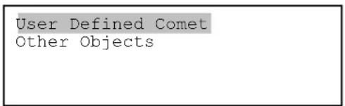
Select "User Defined Comet" to add/browse/delete the user-defined comet list. Find the orbit parameters of a comet in the SkyMap format. For example, the C/2012 ISON has an orbit parameter:
| No. | Name | Year | M | Day | q | e | I | H | G | ||
| C/2012 | S1 ISON | 2013 | 11 | 28.7960 | 0.0125050 | 1.0000030 | 345.5088 | 295.7379 | 61.8570 | 6.0 | 4.0 |
Select "Add a New Comet" to add a new one:
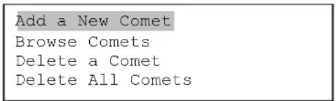
The hand controller will display the parameter entry screen:
| Enter Comet Parameter |
| Date: 0000-00-00.0000 |
| q: 0.000000 |
| e: 0.000000 |
| ω: 000.0000 |
| Ω: 000.0000 |
| i: 000.0000 |
Enter the parameters using the arrow buttons and number keys. Press ENTER and a confirmation screen will be displayed. Press ENTER again to store the object under the assigned user object number, or press BACK button to cancel.
5.8.2. Enter Other Objects or Observation List
Press "MENU => Edit User Objects" to set user objects.
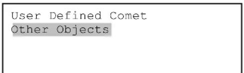
Select "Other Objects" to enter you own object:
Add a New Object
Browse Objects
Delete One Object
Delete All Objects
Select "Add a New Object". A screen will be displayed asking you to Enter R.A. and DEC coordinates:
Enter R.A. and DEC
R.A.: 00h00m00s
DEC: +00d00m00s
You may enter the R.A. and DEC coordinates of the object you want to store, and press ENTER to confirm.
A more useful application of this function is to store your favorite viewing objects before heading to the field. When the "Enter R.A. and DEC" screen appears, press the MENU button. It brings up the catalogs that you can select the object from. Follow the screen instructions to add your favorite objects. Press BACK button to go back one level.
Press the BACK button to go back to the object entry submenu. You may review the records or delete those that are no longer wanted. Press the BACK button to finish the operation. Now you can slew to your favorite stars from "Custom Objects" catalog using "Select and Slew."
5.9. Firmware Information
This option will display the mount type, firmware version information for the hand controller (HC), Main board (Main), R.A. board (RA), DEC board (DEC) and star catalog.
5.10. Zero Position
5.10.1. Goto Zero Position
This moves your telescope to its Zero Position.
This set the Zero Position for the firmware.
The Zero Position reference will be an undefined value after firmware upgrade, or it may lost during power outage or HC battery replacement. You can use this function to set the zero position reference.
Press the ENTER after moving the mount to Zero Position either manually or with the hand controller.
5.10.3. Search Zero Pos.
In the event of power failure, the mount will lose all its alignment information. This can be very troublesome if the mount is being operated from a remote observation site and is controlled via the internet. To counter this, the GEM45 has been equipped with a function that can find the Zero Position for an initial mount set up.
Select "Search Zero Pos." and the mount will start to slew slowly and find the R.A. and DEC position to set the mount to the Zero Position. When the mount has found the Zero Position, the HC will ask if you want to calibrate the Zero Position. Press ENTER to confirm. Use the arrow button to adjust the mount in RA and DEC to correct the obvious discrepancy in the Zero Position. Alternatively, press BACK to cancel.
6. Maintenance and Servicing
6.1. Maintenance
Do not overload the mount. Do not drop the mount as this will damage the mount and / or permanently degrade GoTo performance and tracking accuracy. Use a wet cloth to clean the mount and hand controller. Do not use solvent.
The mount worm/gear meshing can be adjusted to accommodate payload or temperature changed. Please refer to the instruction in Appendix.
The real time clock battery in the hand controller needs be replaced if it can't keep the time after power off the mount.
If your mount is not to be used for an extended period, dismount the OTAs and counterweight(s).
6.2. iOptron Customer Service
If you have any question concerning your GEM45 mount contact iOptron Customer Service Department. Customer Service hours are from 9:00 AM to 5:00 PM, Eastern Time, Monday through Friday. In the event that the GEM45 requires factory servicing or repairing, write or call iOptron Customer Service Department first to receive an RMA# before returning the mount to the factory. Please provide details as to the nature of the problem as well as your name, address, e-mail address, purchase information and daytime telephone number. We have found that most problems can be resolved by e-mails or telephone calls, so please contact iOptron first to avoid returning the mount for repair.
It is strongly suggested that to send technical questions to support@ioptron.com. Call in the U.S. 1.781.569.0200.
6.3. Product End of Life Disposal Instructions
This electronic product is subject to disposal and recycling regulations that vary by country and region. It is your responsibility to recycle your electronic equipment per your local environmental laws and regulations to ensure that it will be recycled in a manner that protects human health and the environment. To find out where you can drop off your waste equipment for recycling, please contact your local waste recycle/disposal service or the product representative.
6.4. Battery Replacement and Disposal Instructions
Battery Disposal: Batteries contain chemicals that, if released, may affect the environment and human health. Batteries should be collected separately for recycling, and recycled at a local hazardous material disposal location adhering to your country and local government regulations. To find out where you can drop off your waste battery for recycling, please contact your local waste disposal service or the product representative.
Appendix A. Technical Specifications
| Mount | German Equatorial Mount (GEM) |
| Max payload* | 45 lbs (20kg), exclude counterweight |
| Mount weight | 17.5 lbs (7.9kg) |
| Payload/Mount weight ratio | 2.53 |
| Structure Material | All metal, CNC machined |
| Exterior finish | Anodized red/black |
| Latitude adjustment range | 14°~ 68° |
| Azimuth adjustment range | ± 6° |
| Right Ascension worm wheel | Φ110mm, 216 teeth aluminum |
| Declination worm wheel | Φ110mm, 216 teeth aluminum |
| PEC | PPEC/Real time PEC |
| Tracking accuracy (PE)** | <±7 arcsec p-p (GEM45, GEM45G), or <0.25 arcsec RMS (GEM45EC) |
| Counterweight shaft | Φ28x 280 mm Stainless Steel (1.2kg) |
| Counterweight | 11 lb (5 kg) |
| Mount base size | Φ120 mm |
| Motor drive | Precision stepper motor, 1.8°/128X micro-step |
| Motor resolution | 0.08 arc seconds |
| Slew speed | 1×,2×,8×,16×,64×,128×,256×,512×,MAX(~4.5°/sec) |
| Power consumption | 0.6A(Tracking), 0.9A(GOTO) |
| Power requirement | 12V DC 5A |
| AC adapter | 100V ~ 240V (included) |
| Polar Scope | Internal iPolarTM electronic polar scope |
| Level indicator | Level bubble |
| Dovetail saddle | 6" Losmandy D & Vixe dual saddle |
| Hand Controller | Go2Nova® 8407+,212,000 objects database, star recognition |
| Meridian treatment | Stop (0-20° pass), auto flip |
| GPS | Yes (external) |
| WIFI | Optional (external) |
| Guiding scope/camera | Built in guiding scope and camera, iGuiderTM (GEM45G) |
| Autoguide port | ST-4 |
| Communication port | USB Port (on the mount) |
| PC computer control | Yes (ASCOM) |
| Cable management | USB2.0, DC12V (MAX 3A), ST4 |
| Operation temperature | -10°C ~ +40°C |
| Tripod | LiteRoc 1.75" Stainless Steel (~8kg), optional tri-pier |
| Warranty | Two year limited |
* OTA size and length dependent
** Bench measured with encoder, 400 seconds
Appendix B. Go2Nova® 8407+ HC MENU STRUCTURE
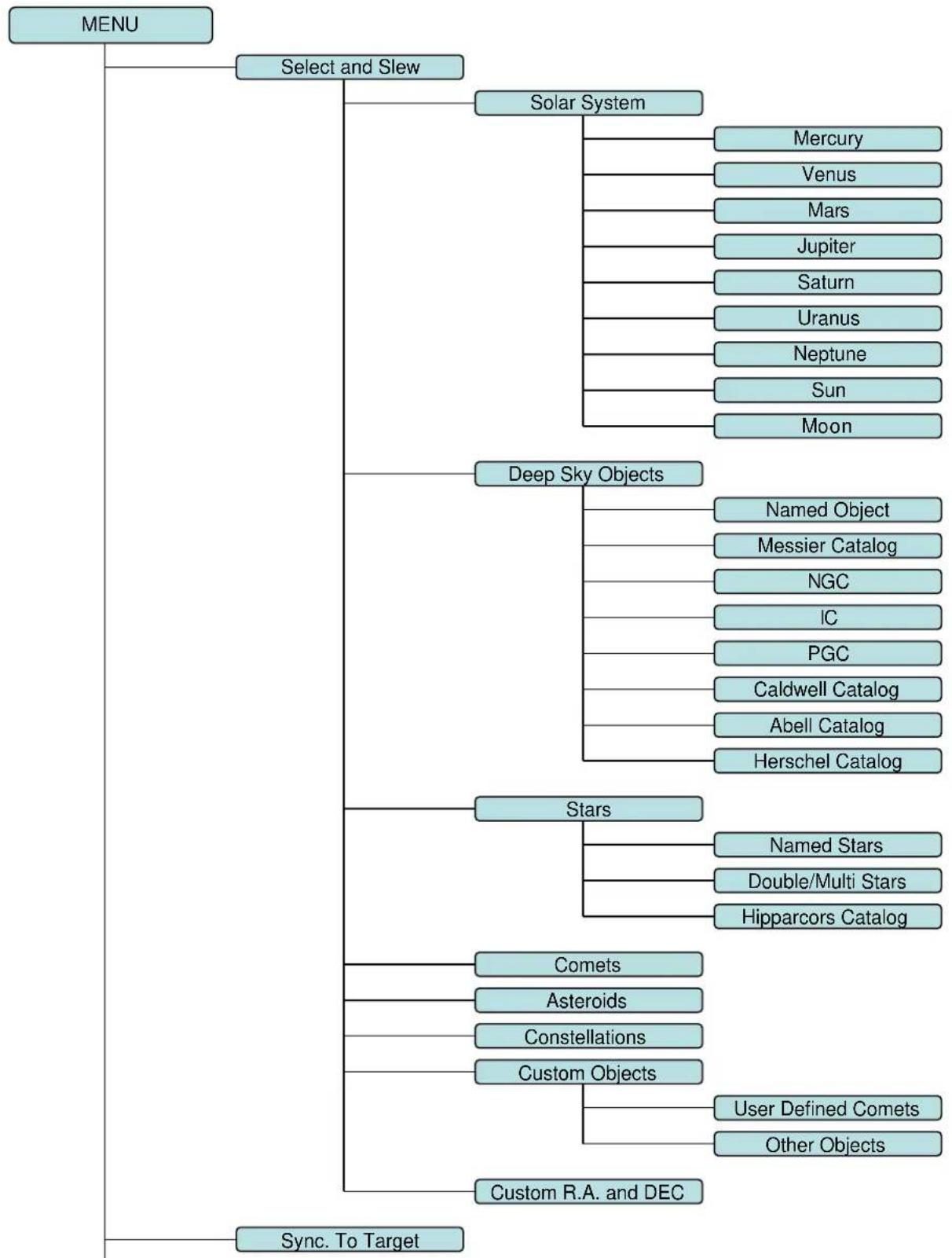
flowchart
graph TD
    A["MENU"] --> B["Select and Slew"]
    B --> C["Solar System"]
    C --> D["Mercury"]
    C --> E["Venus"]
    C --> F["Mars"]
    C --> G["Jupiter"]
    C --> H["Saturn"]
    C --> I["Uranus"]
    C --> J["Neptune"]
    C --> K["Sun"]
    C --> L["Moon"]

    B --> M["Deep Sky Objects"]
    M --> N["Named Object"]
    M --> O["Messier Catalog"]
    M --> P["NGC"]
    M --> Q["IC"]
    M --> R["PGC"]
    M --> S["Caldwell Catalog"]
    M --> T["Abell Catalog"]
    M --> U["Herschel Catalog"]

    B --> V["Stars"]
    V --> W["Named Stars"]
    V --> X["Double/Multi Stars"]
    V --> Y["Hipparcors Catalog"]

    B --> Z["Comets"]
    Z --> AA["Asteroids"]
    Z --> AB["Constellations"]
    Z --> AC["Custom Objects"]
    AC --> AD["User Defined Comets"]
    AC --> AE["Other Objects"]

    B --> AF["Custom R.A. and DEC"]

    B --> AG["Sync. To Target"]
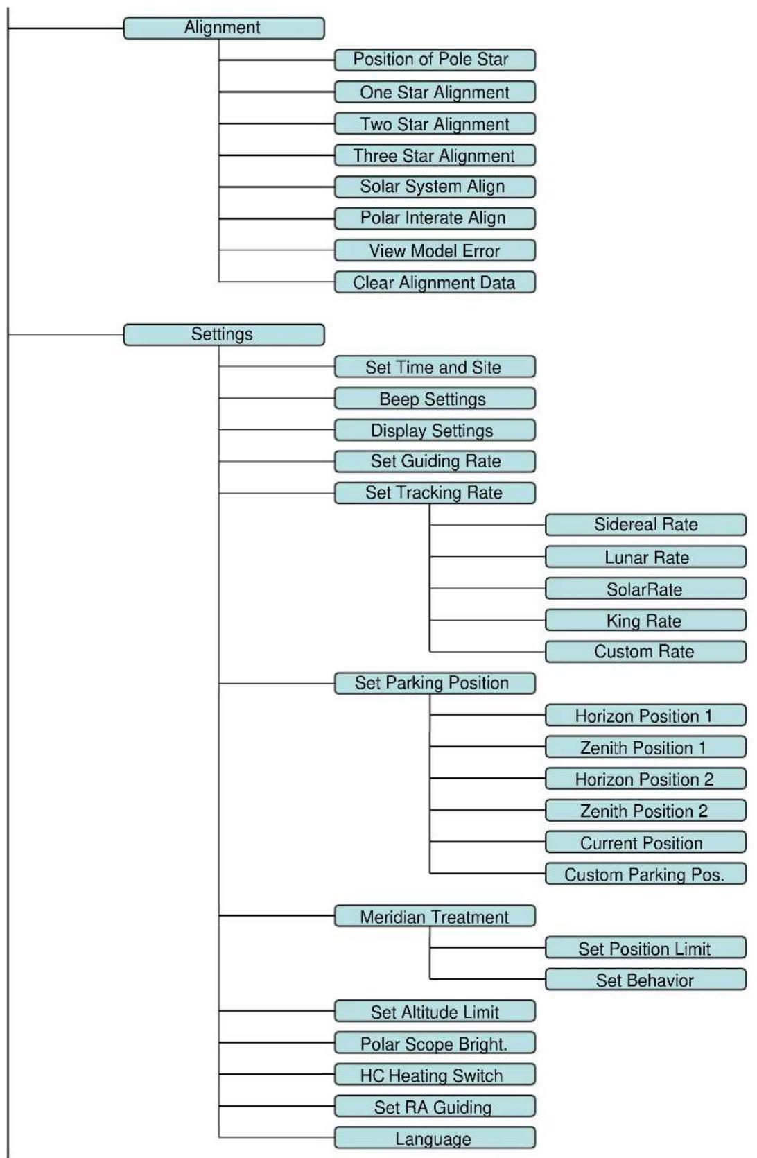
flowchart
graph TD
    A["Alignment"] --> B["Position of Pole Star"]
    A --> C["One Star Alignment"]
    A --> D["Two Star Alignment"]
    A --> E["Three Star Alignment"]
    A --> F["Solar System Align"]
    A --> G["Polar Interate Align"]
    A --> H["View Model Error"]
    A --> I["Clear Alignment Data"]

    J["Settings"] --> K["Set Time and Site"]
    J --> L["Beep Settings"]
    J --> M["Display Settings"]
    J --> N["Set Guiding Rate"]
    J --> O["Set Tracking Rate"]
    O --> P["Sidereal Rate"]
    O --> Q["Lunar Rate"]
    O --> R["SolarRate"]
    O --> S["King Rate"]
    O --> T["Custom Rate"]

    U["Set Parking Position"] --> V["Horizon Position 1"]
    U --> W["Zenith Position 1"]
    U --> X["Horizon Position 2"]
    U --> Y["Zenith Position 2"]
    U --> Z["Current Position"]
    U --> AA["Custom Parking Pos."]

    AB["Meridian Treatment"] --> AC["Set Position Limit"]
    AB --> AD["Set Behavior"]

    AE["Set Altitude Limit"] --> AF["Polar Scope Bright."]
    AE --> AG["HC Heating Switch"]
    AE --> AH["Set RA Guiding"]
    AE --> AI["Language"]
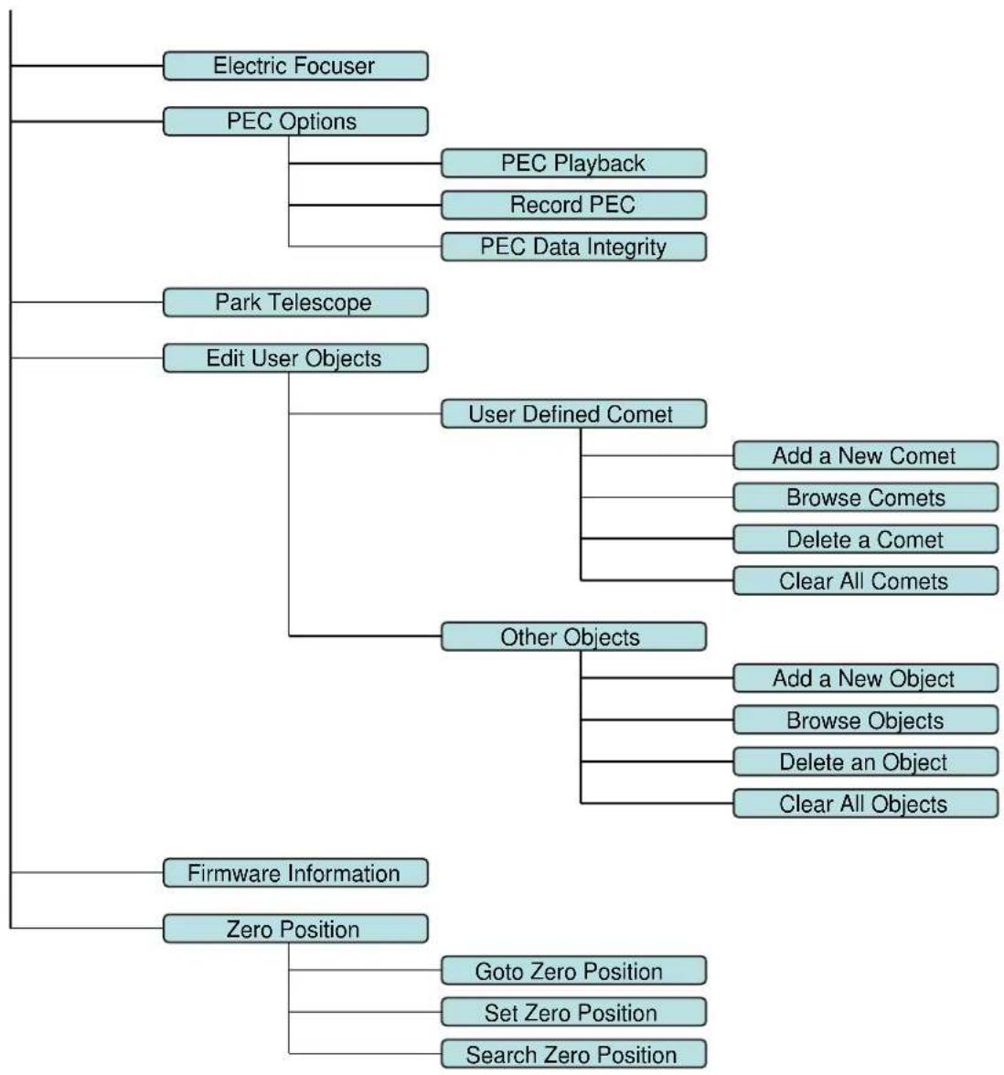
flowchart
graph TD
    A["Firmware Information"] --> B["Zero Position"]
    B --> C["Edit User Objects"]
    C --> D["Park Telescope"]
    D --> E["PEC Options"]
    E --> F["Electric Focuser"]
    C --> G["User Defined Comet"]
    G --> H["Add a New Comet"]
    G --> I["Browse Comets"]
    G --> J["Delete a Comet"]
    G --> K["Clear All Comets"]
    C --> L["Other Objects"]
    L --> M["Add a New Object"]
    L --> N["Browse Objects"]
    L --> O["Delete an Object"]
    L --> P["Clear All Objects"]
    B --> Q["Goto Zero Position"]
    B --> R["Set Zero Position"]
    B --> S["Search Zero Position"]
Appendix C. Go2Nova ^® Star List
Named Deep Sky Object
| 1 47 Tucanae 47 Integral Sign Galaxy | ||
| 2 Andromeda Galaxy 48 Iris Nebula | ||
| 3 Antennae Galaxies 49 Jellyfish Nebula | ||
| 4 Barnard's Galaxy 50 Jewel Box Cluster | ||
| 5 Bear-Paw Galaxy 51 Lagoon Nebula | ||
| 6 Beehive Cluster 52 Lambda Centauri Nebula | ||
| 7 Black Eye Galaxy 53 Large Magellanic Cloud | ||
| 8 Blinking Planetary 54 Leo Triplet | ||
| 9 Blue Flash Nebula 55 Little Dumbbell Nebula | ||
| 10 Blue Planetary 56 Little Gem Nebula | ||
| 11 Blue Snowball Nebula | 57 | Little Ghost Nebula |
| 12 Bode's Galaxy | 58 Mice Galaxies | |
| 13 Box Nebula | 59 Monkey Head Nebula | |
| 14 Bubble Nebula | 60 North America Nebula | |
| 15 Bug Nebula | 61 Northern Jewel Box | |
| 16 Butterfly Cluster | 62 Omega Nebula | |
| 17 Butterfly Galaxies | 63 Orion Nebula | |
| 18 California Nebula | 64 Owl Nebula | |
| 19 Carina Nebula | 65 Pacman Nebula | |
| 20 Cat's Eye Nebula | 66 Pelican Nebula | |
| 21 Cave Nebula | 67 Phantom Streak Nebula | |
| 22 Christmas Tree Cluster | 68 | Pinwheel Galaxy |
| 23 Cigar Galaxy | 69 Plejades | |
| 24 Cocoon Nebula | 70 Ring Nebula | |
| 25 Coma Pinwheel | 71 Rosette Nebula | |
| 26 Copeland Septet | 72 Saturn Nebula | |
| 27 Crab Nebula | 73 Sextans B | |
| 28 Crescent Nebula 74 Small Magellanic Cloud | ||
| 29 Draco Dwarf Galaxy | 75 Sombrero Galaxy | |
| 30 Dumbbell Nebula | 76 Soul Nebula | |
| 31 Eagle Nebula | 77 Southern Pinwheel Galaxy | |
| 32 Eight-Burst Nebula | 78 | Spindle Galaxy(3115) |
| 33 Elephant Trunk Nebula | 79 | Spindle Galaxy(5866) |
| 34 Eskimo Nebula | 80 Stephan's Quintet | |
| 35 Eyes Galaxies | 81 Sunflower Galaxy | |
| 36 Flame Nebula | 82 Tarantula Nebula | |
| 37 Flaming Star Nebula | 83 | The Witch Head Nebula |
| 38 Ghost of Jupiter 84 The Wizard Nebula | ||
| 39 Heart Nebula | 85 Thor's Helmet | |
| 40 Helix Nebula | 86 Triangulum Galaxy | |
| 41 Hercules Globular Cluster | 87 | Trifid Nebula |
| 42 Hind's Variable Nebula | 88 | Ursa Minor Dwarf Galaxy |
| 43 Hockey Stick Galaxies | 89 Veil Nebula | |
| 44 Horsehead Nebula | 90 Whale Galaxy | |
| 45 Hubble's Variable Nebula | 91 Whirlpool Galaxy | |
| 46 Hyades Cluster | 92 Wild Duck Cluster | |
Messier Catalog
natural_image
Grid of 30 astronomical images showing various types of galaxies and star fields in deep space (no text or symbols)This table is licensed under the GNU Free Documentation License. It uses material from the Wikipedia article List of Messier objects
Named Stars
| 1 | Acamar | 50 | Alrescha | 99 | Deneb el Okab | 148 | Lalande 21185 |
| 2 | Achernar | 51 | Alshain | 100 | Deneb Kaitos | 149 | Lesath |
| 3 | Achird 52 Altair 101 Denebakra | b 150 Mahasim | |||||
| 4 | Acrab | 53 | Altais | 102 | Denebola | 151 | Maia |
| 5 | Acrux A | 54 | Alterf | 103 | Dschubba | 152 | Marfik |
| 6 | Acrux B | 55 | Aludra | 104 | Dubhe | 153 | Marfikent |
| 7 | Acubens | 56 | Alula Australis | 105 | Edasich | 154 | Markab |
| 8 | Adhafera | 57 | Alula Borealis | 106 | El Rehla | 155 | Markeb |
| 9 | Adhara | 58 | Alya | 107 | Electra | 156 | Matar |
| 10 | Adid Australis | 59 | Ancha | 108 | Elnath | 157 | Mebsuta |
| 11 | Ahadi | 60 | Ankaa | 109 | Eltanin | 158 | Megrez |
| 12 | Al Dhanab | 61 | Antares | 110 | Enif | 159 | Meissa |
| 13 | Al Dhibain Prior | 62 | Apollyon | 111 | Errai | 160 | Mekbuda |
| 14 | Al Kab | 63 | Arcturus | 112 | Fomalhaut | 161 | Menkalinan |
| 15 | Al Nair | 64 | Arkab Prior | 113 | Furud | 162 | Menkar |
| 16 | Al Nair al Baten | 65 | Arneb | 114 | Gacrux | 163 | Menkent |
| 17 | Al Niyat(Sigma) | 66 | Ascella | 115 | Gatria | 164 | Menkib |
| 18 | Al Niyat(Tau) 67 | Asellus Austral | 116 | Giausar | 165 | Merak | |
| 19 | Albaldah | 68 | Asellus Boreali | 117 | Gienah Corvi | 166 | Merope |
| 20 | Albali | 69 | Aspidiske | 118 | Gienah Cygni | 167 | Mesartim |
| 21 | Albireo | 70 | Atik | 119 | Girtab | 168 | Miaplacidus |
| 22 | Alchiba | 71 | Atlas | 120 | Gliese 1 | 169 | Mimosa |
| 23 | Alcor | 72 | Atria | 121 | Gomeisa | 170 | Mintaka |
| 24 | Alcyone | 73 | Avior | 122 | Graffias(Zeta) | 171 | Mira |
| 25 | Aldebaran | 74 | Azha | 123 | Groombridge 1830 | 172 | Mirach |
| 26 | Alderamin | 75 | Bamard's Star | 124 | Gruid | 173 | Mirfak |
| 27 | Alfirk | 76 | Baten Kaitos | 125 | Grumium | 174 | Mirzam |
| 28 | Algenib | 77 | Beid | 126 | Hadar | 175 | Mizar |
| 29 | Algenubi | 78 | Bellatrix | 127 | Hamal | 176 | Mu Velorum |
| 30 | Algieba | 79 | Beta Hydri | 128 | Han | 177 | Muhlifain |
| 31 | Algiedi Secunda | 80 | Betelgeuse | 129 | Hatsya | 178 | Muphrid |
| 32 | Algol | 81 | Betria | 130 | Head of Hydrus | 179 | Muscida |
| 33 | Algorab | 82 | Biham | 131 | Homam | 180 | Naos |
| 34 | Alhakim | 83 | Birdun | 132 | Iritjinga(Cen) | 181 | Nashira |
| 35 | Alhena | 84 | Canopus | 133 | Izar | 182 | Navi |
| 36 | Alioth | 85 | Capella | 134 | Kakkab Su-gub Gud-Elim | 183 | Nekkar |
| 37 | Alkaid | 86 | Caph | 135 | Kapteyn's Star | 184 | Nihal |
| 38 | Alkalurops | 87 | Castor A | 136 | Kaus Australis | 185 | Nunki |
| 39 | Alkes | 88 | Castor B | 137 | Kaus Borealis | 186 | Nusakan |
| 40 | Almaaz | 89 | Cebalrai | 138 | Kaus Media | 187 | Palida |
| 41 | Almach | 90 | Chara | 139 | Keid | 188 | Peacock |
| 42 | Alnasl | 91 | Chertan | 140 | Kekouan | 189 | Phact |
| 43 | Alnilam | 92 | Choo | 141 | Kitalpha | 190 | Phecda |
| 44 | Alnitak | 93 | Cor Caroli | 142 | Kochab | 191 | Pherkad |
| 45 | Alpha Muscae | 94 | Cursa | 143 | Koo She | 192 | Polaris |
| 46 | Alpha Tucanae | 95 | Dabih | 144 | Kornephoros | 193 | Pollux |
| 47 | Alphard | 96 | Deltotum | 145 | Kraz | 194 | Porrima |
| 48 | Alphecca | 97 | Deneb | 146 | Kurhah | 195 | Procyon |
| 49 | Alpheratz | 98 | Deneb Algedi | 147 | Lacaille 9352 | 196 | Propus |
| 197 | Proxima Centauri | 213 | Sadalbari | 229 | Sulafat | 245 | Vindemiatrix |
| 198 | Rasalas | 214 | Sadalmelik | 230 | Syrma | 246 | Vrischika |
| 199 | Rasalgethi | 215 | Sadalsuud | 231 | Talitha | 247 | Wasat |
| 200 | Rasalhague | 216 | Sadr | 232 | Tania Australis | 248 | Wazn |
| 201 | Rastaban | 217 | Saiph | 233 | Tania Borealis | 249 | Wei |
| 202 | Regor | 218 | Sargas | 234 | Tarazed | 250 | Wezen |
| 203 | Regulus | 219 | Scheat | 235 | Taygeta | 251 | Yed Posterior |
| 204 | Rigel | 220 | Schedar | 236 | Tejat Posterior | 252 | Yed Prior |
| 205 | Rigel Kentaurus A | 221 | Seginus | 237 | Thuban | 253 | Zaniah |
| 206 | Rigel Kentaurus B | 222 | Shaula | 238 | Thusia | 254 | Zaurak |
| 207 | Ruchbah | 223 | Sheliak | 239 | Tien Kwan | 255 | Zavijava |
| 208 | Rukbat | 224 | Sheratan | 240 | Turais | 256 | Zeta Persei |
| 209 | Rukh | 225 | Sirius | 241 | Unukalhai | 257 | Zosma |
| 210 | Rutilicus | 226 | Skat | 242 | Vasat-ul-cemre | 258 | Zubenelgenubi |
| 211 | Sabik | 227 | Spica | 243 | Vathorz Posterior | 259 | Zubeneschamali |
| 212 | Sadachbia | 228 | Suhail | 244 | Vega |
Modern Constellations
| No. | Constellation Abbreviation | |
| 1 | Andromeda And | |
| 2 | Antlia Ant | |
| 3 | Apus Aps | |
| 4 | Aquarius Aqr | |
| 5 | Aquila Aql | |
| 6 | Ara Ara | |
| 7 | Aries Ari | |
| 8 | Auriga Aur | |
| 9 | Boötes Boo | |
| 10 | Caelum Cae | |
| 11 | Camelopardalis | Cam |
| 12 | Cancer | Cnc |
| 13 | Canes Venatici | CVn |
| 14 | Canis Major | CMa |
| 15 | Canis Minor | CMi |
| 16 | Capricornus | Cap |
| 17 | Carina | Car |
| 18 | Cassiopeia | Cas |
| 19 | Centaurus | Cen |
| 20 | Cepheus | Cep |
| 21 | Cetus | Cet |
| 22 | Chamaeleon | Cha |
| 23 | Circinus Cir | |
| 24 | Columba Col | |
| 25 | Coma Berenices | Com |
| 26 | Corona Australis | CrA |
| 27 | Corona Borealis | CrB |
| 28 | Corvus | Crv |
| 29 | Crater | Crt |
| 30 | Crux | Cru |
| 31 | Cygnus Cyg | |
| 32 | Delphinus | Del |
| 33 | Dorado Dor | |
| 34 | Draco | Dra |
| 35 | Equuleus | Equ |
| 36 | Eridanus Eri | |
| 37 | Fornax For | |
| 38 | Gemini | Gem |
| 39 | Grus Gru | |
| 40 | Hercules | Her |
| 41 | Horologium | Hor |
| 42 | Hydra Hya | |
| 43 | Hydrus Hyi | |
| 44 | Indus Ind | |
| No. | Constellation Abbreviation | |
| 45 | Lacerta Lac | |
| 46 | Leo Leo | |
| 47 | Leo Minor LMi | |
| 48 | Lepus Lep | |
| 49 | Libra Lib | |
| 50 | Lupus Lup | |
| 51 | Lynx Lyn | |
| 52 | Lyra Lyr | |
| 53 | Mensa Men | |
| 54 | Microscopium | Mic |
| 55 | Monoceros | Mon |
| 56 | Musca | Mus |
| 57 | Norma Nor | |
| 58 | Octans | Oct |
| 59 | Ophiuchus Oph | |
| 60 | Orion Ori | |
| 61 | Pavo Pav | |
| 62 | Pegasus | Peg |
| 63 | Perseus | Per |
| 64 | Phoenix | Phe |
| 65 | Pictor Pic | |
| 66 | Pisces Psc | |
| 67 | Piscis Austrinus | PsA |
| 68 | Puppis | Pup |
| 69 | Pyxis | Pyx |
| 70 | Reticulum | Ret |
| 71 | Sagitta Sge | |
| 72 | Sagittarius | Sgr |
| 73 | Scorpius | Sco |
| 74 | Sculptor Scl | |
| 75 | Scutum | Sct |
| 76 | Serpens Ser | |
| 77 | Sextans | Sex |
| 78 | Taurus | Tau |
| 79 | Telescopium | Tel |
| 80 | Triangulum | Tri |
| 81 | Triangulum Australe | TrA |
| 82 | Tucana Tuc | |
| 83 | Ursa Major | UMa |
| 84 | Ursa Minor UMi | |
| 85 | Vela | Vel |
| 86 | Virgo Vir | |
| 87 | Volans | Vol |
| 88 | Vulpecula | Vul |
Double/Multi Stars
| No. HC Item Constellation Name HIP WDS SAO | |||||||
| 1 Rigel Kentaurus A Alpha Centauri Centaurus 7 | 1683 14396-6050 | 252838 | |||||
| 2 | Rigel | Beta Orionis | Orion | 24436 | 05145-0812 | 131907 | |
| 3 | Gacrux | Gamma Crucis | Crux | 61084 | 12312-5707 | 240019 | |
| 4 | Sargas | Theta Scorpii | Scorpius | 86228 | 17373-4300 | 228201 | |
| 5 | Castor A | Alpha Geminorum | Gemini | 36850 | 07346+3153 | 60198 | |
| 6 | Mizar | Zeta Ursae Majoris | Ursa Major | 65378 | 13239+5456 | 28737 | |
| 7 | Almach | Gamma Andromedae | Andromeda | 9640 | 02039+4220 | 37735 | |
| 8 | Algieba | Gamma Leonis | Leo | 50583 | 10200+1950 | 81298 | |
| 9 | Aludra | Eta Canis Majoris | Canis Major | 35904 | 07241-2918 | 173651 | |
| 10 | Iritjinga (Cen) | Gamma Centauri | Centaurus | Muhlifain | 61932 | 12415-4858 | 223603 |
| 11 | Zubenelgenubi | Alpha Librae | Libra | 72603 | 14509-1603 | 158836 | |
| 12 | Alcyone | Eta Tauri | Taurus | 17702 | 03475+2406 | 76199 | |
| 13 Cor Caroli | Alpha Canum Venatico | Canes Venatici | 63125 | 12560+3819 | 63257 | ||
| 14 | Acamar | Theta Eridani | Eridanus | 13847 | 02583-4018 | 216113 | |
| 15 | Adhafera | Zeta Leonis | Leo | 50335 | 10167+2325 | 81265 | |
| 16 | Rasalgethi | Alpha Herculis | Hercules | 84345 | 17146+1423 | 102680 | |
| 17 | Meissa | Lambda Orionis | Orion | 26207 | 05351+0956 | 112921 | |
| 18 | Graffias | Beta1 Scorpii | Scorpius | 78820 | 16054-1948 | 159682 | |
| 19 | Alya | Theta Serpentis | Serpens | 92946 | 18562+0412 | 124068 | |
| 20 | HIP 48002 | Upsilon Carinae | Carina | Vathorz Prior | 09471-6504 | 250695 | |
| 21 | HIP 95947 | Beta1 Cygni | Cygnus | Albireo | 19307+2758 | 87301 | |
| 22 | HIP 20894 | Theta2 Tauri | Taurus | 04287+1552 | 93957 | ||
| 23 | HIP 74395 | Zeta Lupi | Lupus | 15123-5206 | 242304 | ||
| 24 | HIP 27072 | Gamma Leporis | Lupus | 05445-2227 | 170759 | ||
| 25 | HIP 26549 | Sigma Orionis | Orion | 05387-0236 | 132406 | ||
| 26 | HIP 85667 | HD 158614 | Ophiuchus | 17304-0104 | 141702 | ||
| 27 | HIP 74376 | Kappa1 Lupi | Lupus | 15119-4844 | 225525 | ||
| 28 | HIP 34481 | Gamma2 Volantis | Carina | 07087-7030 | 256374 | ||
| 29 | HIP 53253 | u Carinae | Carina | 10535-5851 | 238574 | ||
| 30 | HIP 99675 | Omicron1 Cygni | Cygnus | 31 Cyg | 20136+4644 | 49337 | |
| 31 | HIP 63003 | Mu1 Crucis | Crux | 12546-5711 | 240366 | ||
| 32 | HIP 43103 | Iota Cancri | Cancer | 48 Cnc | 08467+2846 | 80416 | |
| 33 | HIP 110991 | Delta Cephei | Cepheus | 27 Cep | 22292+5825 | 34508 | |
| 34 | HIP 20635 | Kappa1 Tauri | Taurus | 65 Tau | 04254+2218 | 76601 | |
| 35 | HIP 88601 | 70 Ophiuchi | Orion | 18055+0230 | 123107 | ||
| 36 | HIP 2484 | Beta1 Tucanae | Horologium | 00315-6257 | 248201 | ||
| 37 | HIP 91971 | Zeta1 Lyrae | Cygnus | 6 Lyr | 18448+3736 | 67321 | |
| 38 | HIP 79374 | Nu Scorpii | Scorpius | Jabbah | 16120-1928 | 159764 | |
| 39 | HIP 102532 | Gamma2 Delphini | Pegasus | 12 Del | 20467+1607 | 106476 | |
| 40 | HIP 52154 | x Velorum | Vela | 10393-5536 | 238309 | ||
| 41 | HIP 37229 | HD 61555 | Canis Major | 07388-2648 | 174198 | ||
| 42 | HIP 30419 | Epsilon Monocerotis | Orion | 8 Mon | 06238+0436 | 113810 | |
| 43 | HIP 108917 | Xi Cephei | Cepheus. | Al kurhah | 22038+6438 | 19827 | |
| 44 | HIP 53417 | 54 Leonis | Leo | 10556+2445 | 81584 | ||
| 45 | HIP 65271 | J Centauri | Centaurus | 13226-6059 | 252284 | ||
| 46 | HIP 67669 | 3 Centauri | Centaurus | 13518-3300 | 204916 | ||
| 47 | HIP 105319 | Theta Indi | Indus | 21199-5327 | 246965 | ||
| 48 | HIP 80582 | Epsilon Normae | Norma | 16272-4733 | 226773 | ||
| 49 | HIP 8832 | Gamma Arietis | Aries | 01535+1918 | 92680 | ||
| 50 | HIP 69483 | Kappa Boötis | Boötes | Asellus Tertius | 14135+5147 | 29045 | |
| 51 | HIP 92946 | Theta Serpentis | Serpens | 18562+0412 | 124068 | ||
| 52 | HIP 86614 | Psi1 Draconis | Draco | 31 Draconis | 17419+7209 | 8890 | |
No. HC Item Constellation Name HIP WDS SAO
| 53 H | P 95771 Alpha Vulpeculae Vulpecula Anser | 19287+2440 87261 | |||||
| 54 | HIP 30867 | Beta Monocerotis | Monoceros | 06288-0702 | 133316 | ||
| 55 | HIP 35363 | NV Puppis | Puppis | 07183-3644 | 197824 | ||
| 56 | HIP 94761 | Gliese 752 | Aquila | Wolf 1055, Ross 652 | 19169+0510 | ||
| 57 H | P 21683 Sigma2 Tauri Taurus | 04393+1555 94054 | |||||
| 58 | HIP 8497 | Chi Ceti | Cetus | 53 Cet | 01496-1041 | 148036 | |
| 59 | HIP 26199 | HD 36960 | Orion | 05350-0600 | 132301 | ||
| 60 | HIP 104521 | Gamma Equulei | Equuleus | 5 Equ | 21103+1008 | 126593 | |
| 61 | HIP 116389 | Iota Phoenicis | Phoenix | 23351-4237 | 231675 | ||
| 62 | HIP 17797 | HD 24071 | Eridanus | 03486-3737 | 194550 | ||
| 63 | HIP 21036 | 83 Tauri | Taurus | 04306+1343 | 93979 | ||
| 64 | HIP 107310 | Mu1 Cygni | Cygnus | 78 Cyg | 21441+2845 | 89940 | |
| 65 | HIP 72659 | Xi Boötis | Boötes | 37 Boo | 14514+1906 | 101250 | |
| 66 | HIP 21029 | HD 28527 | Taurus | 04306+1612 | 93975 | ||
| 67 | HIP 42726 | HY Velorum | Vela | 08424-5307 | 236205 | ||
| 68 | HIP 18255 | 32 Eridani | Eridanus | 03543-0257 | 130806 | ||
| 69 | HIP 9153 | Lambda Arietis | Aries | 01580+2336 | 75051 | ||
| 70 | HIP 88267 | 95 Herculis | Hercules | 18015+2136 | 85648 | ||
| 71 | HIP 85829 | Nu2 Draconis | Draco | 25 Dra | 17322+5511 | 30450 | |
| 72 | HIP 43937 | V376 Carinae | Carina | b1 Carinae | 08570-5914 | 236436 | |
| 73 | HIP 71762 | Pi2 Boötis | Boötes | 29 Boo | 14407+1625 | 101139 | |
| 74 | HIP 80047 | Delta1 Apodis | Apus | 16203-7842 | 257380 | ||
| 75 H | P 58484 | Epsilon Chamaeleontis | Chamaeleon | 11596-7813 | 256894 | ||
| 76 | HIP 25142 | 23 Orionis | Orion | 05228+0333 | 112697 | ||
| 77 | HIP 54204 | Chi1 Hydrae | Hydra | 11053-2718 | 179514 | ||
| 78 | HIP 76669 | Zeta Coronae Borealis | Corona Borealis | 7 CrB | 15394+3638 | 64833 | |
| 79 | HIP 99770 | b3 Cygni | Cygnus | 29 Cyg | 20145+3648 | 69678 | |
| 80 | HIP 101027 | Rho Capricorni | Capricornus | 11 Cap | 20289-1749 | 163614 | |
| 81 | HIP 74911 | Nu Lupi | Lupus | 15185-4753 | 225638 | ||
| 82 | HIP 35210 | HD 56577 | Canis Major | 07166-2319 | 173349 | ||
| 83 | HIP 26235 | Theta2 Orionis | Orion | 43 Ori | 05354-0525 | 132321 | |
| 84 | HIP 40321 | OS Puppis | Puppis | 08140-3619 | 198969 | ||
| 85 | HIP 70327 | HD 126129 | Boötes | 14234+0827 | 120426 | ||
| 86 | HIP 26221 | Theta1 Orionis | Orion | Trapezium | 05353-0523 | 132314 | |
| 87 | HIP 80473 | Rho Ophiuchi | Ophiuchus | 5 Oph | 16256-2327 | 184381 | |
| 88 | HIP 78105 | Xi1 Lupi | Lupus | 15569-3358 | 207144 | ||
| 89 | HIP 79043 | Kappa Herculis | Hercules | 7 Her | 16081+1703 | 101951 | |
| 90 | HIP 61418 | 24 Comae Berenices | Coma Berenices | 12351+1823 | 100160 | ||
| 91 | HIP 91919 | Epsilon Lyrae | Lyra | 4 Lyr | 18443+3940 | 67309 | |
| 92 | HIP 41639 | HD 72127 | Vela | 08295-4443 | 219996 | ||
| 93 | HIP 104214 | 61 Cygni | Cygnus | 21069+3845 | 70919 | ||
| 94 | HIP 23734 | 11 Camelopardalis | Camelopardalis | 05061+5858 | 25001 | ||
| 95 | HIP 60189 | Zeta Corvi | Corvus | 5 Crv | 12206-2213 | 180700 | |
| 96 | HIP 66821 | Q Centauri | Centaurus | 13417-5434 | 241076 | ||
| 97 | HIP 14043 | HD 18537 | Perseus | 03009+5221 | 23763 | ||
| 98 | HIP 5737 | Zeta Piscium | Pisces | 86 Psc | 01137+0735 | 109739 | |
| 99 | HIP 84626 | Omicron Ophiuchi | Ophiuchus | 39 Oph | 17180-2417 | 185238 | |
| 100 | HIP 60904 | 17 Comae Berenices | Coma Berenices | 12289+2555 | 82330 | ||
| 101 | HIP 58684 | 67 Ursae Majoris | Ursa Major | 12021+4303 | 44002 | ||
| 102 | HIP 5131 | Psi1 Piscium | Pisecs | 74 Psc | 01057+2128 | 74482 | |
| 103 | HIP 115126 | 94 Aquarii | Aquarius | 23191-1328 | 165625 | ||
| 104 | HIP 62572 | HD 112028 | Camelopardalis | 12492+8325 | 2102 | ||
No. HC Item Constellation Name HIP WDS SAO
| 105 H | HIP 40167 Zeta1 Candri Cancer Tegmen 0812 | 2+1739 97645 | |||||
| 106 | HIP 40817 | Kappa Volantis | Volans | 08198-7131 | 256497 | ||
| 107 | HIP 81292 | 17 Draconis | Draco | 16362+5255 | 30013 | ||
| 108 | HIP 80197 | Nu1Coronae Borealis | Corona Borealis | 16224+3348 | 65257 | ||
| 109 | HIP 88060 | HD 163756 | Sagittarius | 17591-3015 | 209553 | ||
| 110 | HIP 42637 | Eta Chamaeleontis | Chamaeleon | 08413-7858 | 256543 | ||
| 111 | HIP 21039 | 81 Tauri | Taurus | 04306+1542 | 93978 | ||
| 112 | HIP 100965 | 75 Draconis | Draco | 20282+8125 | 3408 | ||
| 113 | HIP 25768 | HD 36553 | Pictor | 05302-4705 | 217368 | ||
| 114 | HIP 93717 | 15 Aquilae | Aquila | 19050-0402 | 142996 | ||
| 115 | HIP 79980 | HD 148836 | Scorpius | 16195-3054 | 207558 | ||
| 116 | HIP 12086 | 15 Trianguli | Triangulum | 02358+3441 | 55687 | ||
| 117 H | HIP 90968 | Kappa2 Coronae Austra | Corona Australis | 18334-3844 | 21029 | ||
| 118 | HIP 22531 | Iota Pictoris | Pictor | 04509-5328 | 233709 | ||
| 119 | HIP 34065 | HD 53705 | Puppis | 07040-4337 | 218421 | ||
| 120 H | HIP 79607 | Sigma Coronae Boreali | Corona Borealis | 16147+3352 | 65165 | ||
| 121 | HIP 109786 | 41 Aquarii | Aquarius | 22143-2104 | 190986 | ||
| 122 | HIP 56280 | 17 Crateris | Hydra | 11323-2916 | 179968 | ||
| 123 | HIP 51561 | HD 91355 | Vela | 10320-4504 | 222126 | ||
| 124 | HIP 107930 | HD 208095 | Cepheus | 21520+5548 | 33819 | ||
| 125 | HIP 97966 | 57 Aquilae | Aquila | 19546-0814 | 143898 | ||
| 126 | HIP 117218 | 107 Aquarii | Aquarius. | 23460-1841 | 165867 | ||
| 127 | HIP 82676 | HD 152234 | Scorpius | 16540-4148 | 227377 | ||
| 128 | HIP 111546 | 8 Lacertae | Lacerta | 22359+3938 | 72509 | ||
| 129 | HIP 29151 | HD 42111 | Orion | 06090+0230 | 113507 | ||
| 130 | HIP 107253 | 79 Cygni | Cygnus | 21434+3817 | 71643 | ||
| 131 | HIP 88136 | 41 Draconis | Draco | 18002+8000 | 8996 | ||
| 132 | HIP 81702 | HD 150136 | Ara | 16413-4846 | 227049 | ||
| 133 | HIP 97423 | HD 186984 | Sagittarius | 19480-1342 | 162998 | ||
| 134 | HIP 30444 | HD 45145 | Columba | 06240-3642 | 196774 | ||
| 135 | HIP 66400 | HD 118349 | Hydra | 13368-2630 | 181790 | ||
| 136 | HIP 17579 | 21 Tauri | Taurus | Asterope | 03459+2433 | 76159 | |
| 137 | HIP 35785 | 19 Lyncis | Lynx | 07229+5517 | 26312 | ||
| 138 | HIP 81641 | 37 Herculis | Hercules | 16406+0413 | 121776 | ||
| 139 | HIP 7751 | p Eridani | Eridanus | 01398-5612 | 232490 | ||
| 140 H | HIP 21148 1 Camelopardalis Camelopardalis | 04320+5355 24672 | |||||
| 141 | HIP 9021 | 56 Andromedae | Andromeda | 01562+3715 | 55107 | ||
| 142 | HIP 97816 | HD 187420 | Telescopium | 19526-5458 | 246311 | ||
| 143 | HIP 88818 | 100 Herculis | Hercules | 18078+2606 | 85753 | ||
| 144 | HIP 36817 | HD 60584 | Puppis | 07343-2328 | 174019 | ||
| 145 | HIP 25695 | HD 35943 | Taurus | 05293+2509 | 77200 | ||
| 146 | HIP 98819 | 15 Sagittae | Sagitta | 20041+1704 | 105635 | ||
| 147 | HIP 61910 | VV Corvi | Corvus | 12413-1301 | 157447 | ||
| 148 | HIP 111643 | Sigma2 Gruis | Grus | 22370-4035 | 231217 | ||
| 149 | HIP 80399 | HD 147722 | Scorpius | 16247-2942 | 184368 | ||
| 150 | HIP 83478 | HD 154228 | Hercules | 17037+1336 | 102564 | ||
| 151 | HIP 101123 | Omicron Capricorni | Capricornus | 20299-1835 | 163626 | ||
| 152 | HIP 28271 | 59 Orionis | Orion | 05584+0150 | 113315 | ||
| 153 H | HIP 64246 | 17 Canum Venaticicoru | Canes Venatici | 13101+3830 | 63380 | ||
| 154 | HIP 96895 | 16 Cygni | Cygnus | 19418+5032 | 31898 | ||
| 155 | HIP 35564 | HD 57852 | Carina | 07204-5219 | 235110 | ||
| 156 | HIP 37843 | 2 Puppis | Puppis | 07455-1441 | 153363 | ||
No. HC Item Constellation Name HIP WDS SAO
| 157 H | IP 28790 HD 41742 | Puppis 06047-4505 217 | 706 | ||||
| 158 | HIP 4675 | HD 5788 | Andromeda | 01001+4443 | 36832 | ||
| 159 | HIP 31676 | 8 Lyncis | Lynx | 06377+6129 | 13897 | ||
| 160 | HIP 10176 | 59 Andromedae | Andromeda | 02109+3902 | 55330 | ||
| 161 | HIP 25950 | HD 36408 | Taurus | 05322+1703 | 94630 | ||
| 162 | HIP 117931 | AL Sculptoris | Sculptor | 23553-3155 | 214860 | ||
| 163 | HIP 81914 | HD 150591 | Scorpius | 16439-4107 | 227123 | ||
| 164 | HIP 21242 | m Persei | Perseus | 04334+4304 | 39604 | ||
| 165 | HIP 86831 | 61 Ophiuchi | Ophiuchus | 17446+0235 | 122690 | ||
| 166 | HIP 115272 | HD 220003 | Grus | 23208-5018 | 247838 | ||
| 167 | HIP 46657 | Zeta1 Antliae | Antlia | 09308-3153 | 200444 | ||
| 168 | HIP 41404 | Phi2 Cancri | Cancer | 08268+2656 | 80188 | ||
| 169 | HIP 29388 | 41 Aurigae | Auriga | 06116+4843 | 40925 | ||
| 170 H | IP 49321 HD 87344 | Hydra | 10040-1806 | 155704 | |||
| 171 | HIP 84054 | 63 Herculis | Hercules | 17111+2414 | 84896 | ||
| 172 H | IP 39035 HD 66005 | Puppis 07592-4959 219 | 249 | ||||
| 173 | HIP 25303 | Theta Pictoris | Pictor | 05248-5219 | 233965 | ||
| 174 H | IP 52520 HD 93344 | Carina | 10443-7052 | 256750 | |||
| 175 | HIP 95398 | 2 Sagittae | Sagitta | 19244+1656 | 104797 | ||
| 176 U | CAC4 277-135548 | ||||||
| 177 | HIP 32609 | HD 48766 | Lynx | 06482+5542 | 25963 | ||
| 178 | HIP 101765 | 48 Cygni | Cygnus | 20375+3134 | 70287 | ||
| 179 | HIP 24825 | YZ Leporis | Lepus | 05193-1831 | 150335 | ||
| 180 | HIP 31158 | 21 Geminorum | Gemini | 06323+1747 | 95795 | ||
| 181 | HIP 3885 | 65 Piscium | Pisces | 00499+2743 | 74295 | ||
| 182 | HIP 93371 | HD 176270 | Australis | 19011-3704 | 210816 | ||
| 183 H | IP 36345 HD 59499 | Puppis 07289-3151 198 | 038 | ||||
| 184 | HIP 108364 | HD 208947 | Cepheus | 21572+6609 | 19760 | ||
| 185 | HIP 50939 | HD 90125 | Sextans | 10242+0222 | 118278 | ||
| 186 | HIP 76603 | HD 139461 | Libra | 15387-0847 | 140672 | ||
| 187 H | IP 32269 HD 49219 | Carina | 06442-5442 | 234683 | |||
| 188 | HIP 42516 | 39 Cancri | Cancer | 08401+2000 | 80333 | ||
| 189 | HIP 62807 | 32 Comae Berenices | Coma Berenices | 12522+1704 | 100309 | ||
| 190 U | CAC4 226-128246 | ||||||
| 191 | HIP 94913 | 24 Aquilae | Aquila | 19188+0020 | 124492 | ||
| 192 | HIP 94336 | HD 179958 | Cygnus | 19121+4951 | 48193 | ||
| 193 | HIP 107299 | HD 206429 | Indus | 21440-5720 | 247151 | ||
| 194 | HIP 59984 | HD 106976 | Virgo | 12182-0357 | 138704 | ||
| 195 | HIP 16411 | HD 21743 | Taurus | 03313+2734 | 75970 | ||
| 196 H | IP 23287 HD 32040 | Orion | 05006+0337 | 112305 | |||
| 197 | HIP 105637 | HD 203857 | Cygnus | 21238+3721 | 71280 | ||
| 198 | HIP 108925 | HD 209744 | Cepheus | 22039+5949 | 34016 | ||
| 199 | HIP 103814 | HD 200011 | Microscopium | 21022-4300 | 230492 | ||
| 200 | HIP 58112 | 65 Ursae Majoris | Ursa Major | 11551+4629 | 43945 | ||
| 201 | HIP 109354 | V402 Lacertae | Lacerta | 22093+4451 | 51698 | ||
| 202 | HIP 43822 | 17 Hydrae | Hydra | 08555-0758 | 136409 | ||
| 203 | HIP 21986 | 55 Eridani | Eridanus | 04436-0848 | 131442 | ||
| 204 | HIP 17470 | HD 23245 | Taurus | 03446+2754 | 76122 | ||
| 205 H | IP 35960 V368 Puppis | Puppis 07248-3717 | 197974 | ||||
| 206 | HIP 42936 | HD75086 | Carina | 08451-5843 | 236241 | ||
| 207 | HIP 19272 | SZ Camelopardalis | Camelopardalis | 04078+6220 | 13031 | ||
| 208 | HIP 76143 | HD 138488 | Libra | 15332-2429 | 183565 | ||
Appendix D. Gear Meshing Adjustment
GEM45 gear is designed adjustable by customer although in most cases not necessary. If you experienced DEC/RA motor stall occasionally, or there is free play between the worm and gear, follow this instruction to adjust the gear meshing.
Tool needed: 2mm and 3mm hex keys.
To Adjust DEC Gear:
Disengage DEC gear switch
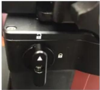
natural_image
Close-up of a black mechanical device handle with a circular knob and adjustment knob (no visible text or symbols)Rotate DEC saddle to exposure the small hole (3mm in diameter) that is blocked by the dovetail saddle. Another larger hole (5mm) is located on the side of the DEC gear housing. There is a set screw inside the 3mm hole which locks the gear meshing adjustment screw, which is inside the larger hole.
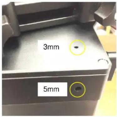
Engage the worm/gear by turn the gear switch to locking position.
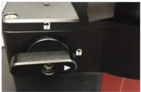
natural_image
Close-up of a black mechanical lock mechanism with a handle and lock symbol (no text or labels visible)Insert the 2mm hex key into the small hole on the top. Gently turn the hex key until you feel it is engaged to the set screw inside. You may turn the gear switch further in the lock position if the wrench can't engage the set screw. Turn the set screw half a turn counterclockwise to release it.
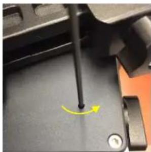
natural_image
Close-up of a mechanical component with a yellow curved arrow indicating rotation or motion (no text or symbols visible)Adjust the gear adjustment screw on the side inside the large hole by using the 3mm hex key. Turn counterclockwise to loosen the meshing or turn clockwise to tighten the meshing.
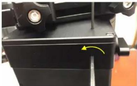
natural_image
Close-up of a black mechanical component with a yellow arrow indicating a specific point on a surface (no text or symbols visible)If the motor stalls or the mount does not tracking smoothly, most likely the meshing is too tight. You may loosen it by about 1/8 turn (or less for tracking). Tighten the set screw in the small hole to LOCK the gear screw (important) before test the mount. Adjust again if needed, but no more than 14 turn in total.
If you feel there is free play between the worm and gear, you may tighten the gear screw to eliminate it.
To Adjust RA Gear:
The RA gear meshing adjustment screw is located next to the RA Gear Switch. The adjustment is same as that for DEC gear/worm.
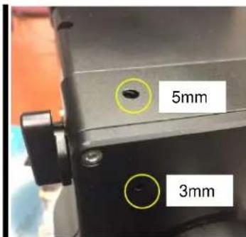
DO NOT over tighten the gear meshing adjustment plunger to avoid damage it.
Please contact support@ioptron.com if you need more information.
Appendix E. Polar Alignment using iPolar Electronic PolarScope
Connect iPolar to a PC and Download iPolar Software
(1) Connect the iPolar Electronic Polar Scope to your PC USB port;
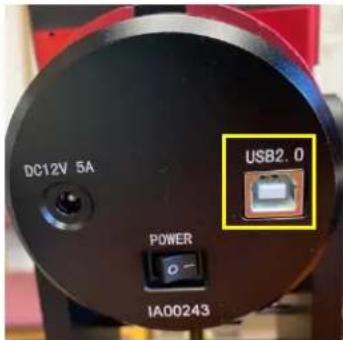
(2) The iPolar driver will be automatically installed if it is the first time connecting to the computer;
(3) You should see "iOptron iPolar" under Camera catalog in computer Device Manager;
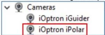
(4) Goto www.ioptron.com to download iPolar software and save on your computer;
(5) The iPolar software needs Windows 7, 8.1, 10 or later version, 32 bit or 64 bit operation system, with .NET Framework 4.8 or later version.
Please refer to iPolar #3339 product page for latest firmware and Instruction Manual:
iPolar Software: https://www.ioptron.com/v/firmware/3339_iOptron_iPolar.exe
Instruction Manual: https://www.ioptron.com/v/manuals/3339_iPolarOperationManual.pdf
Appendix F. iGuider for GEM45G
GEM45G has a built-in iOptron iGuider ^TM guiding system. It includes a 30mm diameter and 120mm focal length guiding scope and a Windows based driverless guiding camera.
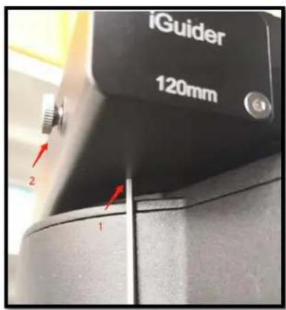
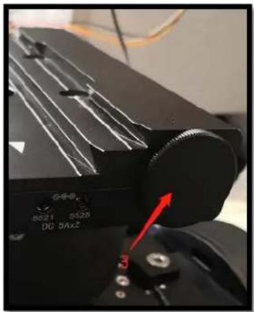
- Focus adjuster locking screw (2mm hex), 2. Focus adjuster, 3. Lens cover
The iGuider only support ASCOM guiding (no ST-4 connection). PHD2 guiding software has the camera included. If you are using other planetarium software, you can install iPolar ASCOM driver.
1. Connect iGuider to a PC
The iGuider guiding system is connected internally to the mount main USB port. GEM45G is connected to the USB2.0 port on the rear end of mount RA axle.
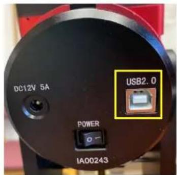
Connect the mount to a PC via a USB cable. Check your PC device list via Device Manager. You should see an iOptron iGuider under the Camera.
2. Setup PHD2 Guiding
Download freeware PHD2 autoguiding software from https://openphdguiding.org/downloads/. Please select V2.6.7 or later version.
Start the PHD2 to start New Profile Wizard:
Click on Next. Select "iOptron iGuider (ASCOM Camera)" from the camera selection menu.
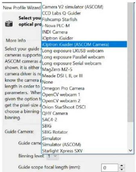
PHD2 will fill the pixel size (3.75um) automatically, if the camera is connected to the computer Enter 120mm into guide scope focal length tab, and click Next.
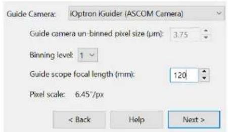
If the program displays the following error, please exit "iOptron iPolar" software.
Select a mount that connected to the computer via ASCOM from the dropdown menu. Here "iOptron CEM120/70/40/26,GEM45/28 Mount (ASCOM)" is selected. A default guiding speed is 0.5X. Click Next.
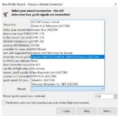
In next Adaptive Optics Device setting window, select None and go to Next.
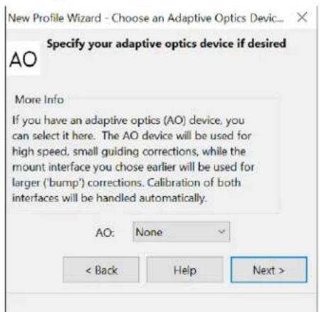
Save the Profile Name. Do not check Build dark library. You may do it at a late time. Click Finish to complete the Profile setup.
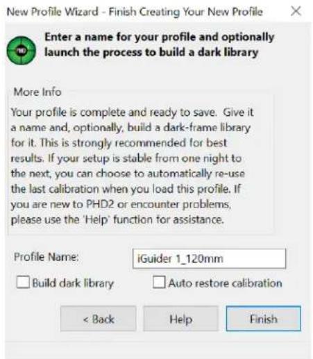
Click on Guide/Connect Equipment and connect all the devices.
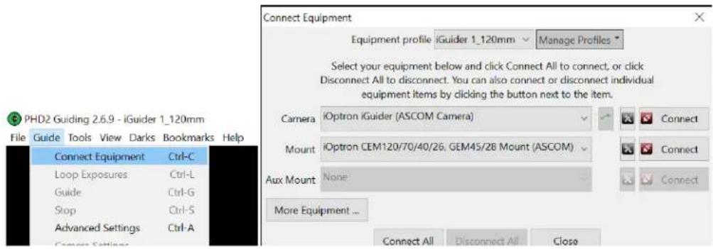
To view the image via iGuider, check "Display Toolbar" and "Display Star Profile" in View menu.
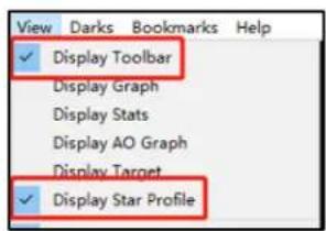
Select proper "Exposure Time" in Main tool bar and click on "Continues Exposure", you should see star images in the main window. Make sure you remove the lens cover.
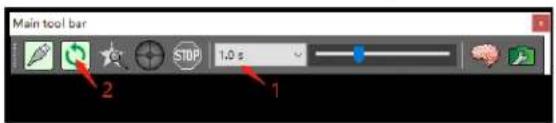
You may also check the iGuider camera during daytime by checking Show Preview in iOptron iGuider ASCOM window. Adjust Exposure Time and focuser to show the image.
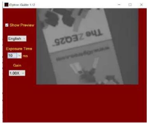
3. iGuiding Focus Adjustment
If you are using the iGudier the first time, you may need to adjust the guiding camera focusing.
Set up the mount. Connect the mount to a computer. Perform polar alignment. Set the Zero Position.
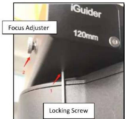
To adjust iGuider focus:
(1) Manually slew in DEC to expose the Locking Screw. Loosen it first.
(2) Remove iGuider lens cover.
(3) Run PHD2 software and select iOptron iGuider
(4) Go to a bright star
(5) Slide the Focus Adjuster to adjust the focus and bring the star to be shown in the main window.
(6) Click on the star to look at the Star Profile. Fine adjusting the Focus Adjuster to bring the Peak to maximum value.
(7) Slew the DEC to expose the Locking Screw if it is blocked by the DEC gear box. Tighten the Locking Screw.
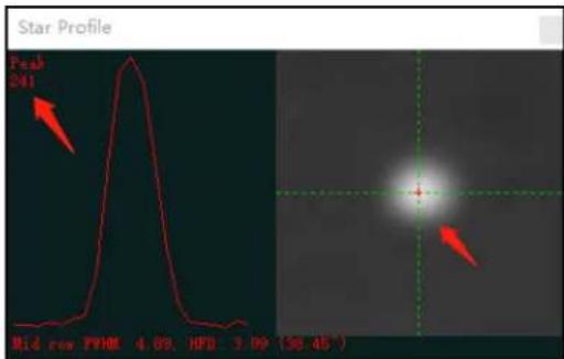
4. Specifications
| Guiding scope aperture | 30mm |
| Focal length | 120mm |
| Imaging sensor | 1/3 in CMOS |
| Pixel size | 3.75μm |
| Resolution | 1280X960 |
| Operation system | Windows (driverless) |
Appendix G. Firmware Upgrade
The firmware in the 8407+ Hand Controller and control boards can be upgraded by the customer. Please check iOptron's website, www.iOptron.com, under Support Documents of the GEM45 product page.
The mount firmware is upgraded via USB port on the mount. The hand controller firmware is upgraded via RS232 port on HC.
Appendix H. Computer Control a GEM45 Mount
The GEM45 mount can be controlled by a SmartPhone, a tablet or a computer. It is supported by two types of computer connections:
- Connect to a computer via USB port on the mount main board using a USB cable. You may need to install a FTDI USB to RS232 VCP driver (https://www.ftdichip.com/Drivers/VCP.htm). The mount can be controlled via ASCOM protocol (Windows OS), or directly by some software, such as Sky Safari (Mac OS).
- Connect wirelessly with iOptron iStarFi adapter for GEM45 (#7434). The mount can be controlled via ASCOM protocol (Windows OS), SmartPhone/Pad and Mac OS wirelessly. See iStarFi Instruction Manual for detailed information.
To control the mount via ASCOM protocol, you'll need:
- Download and install the latest ASCOM Platform, currently 6.4 SP1, from http://www.ascom-standards.org/. Make sure your PC meets the software requirement.
- Download and install the latest iOptron Telescope ASCOM/Commander for GEM45 from iOptron website.
- Planetarium software that supports ASCOM protocol. Follow software instructions to select the iOptron Telescope.
Please refer to iOptron website, www.iOptron.com, under Support Directory/ASCOM Driver, iOptron Telescope ASCOM Driver, for more detail.
IOPTRON TWO YEAR TELESCOPE, MOUNT, AND CONTROLLER WARRANTY
A. iOptron warrants your telescope, mount, or controller to be free from defects in materials and workmanship for two years. iOptron will repair or replace such product or part which, upon inspection by iOptron, is found to be defective in materials or workmanship. As a condition to the obligation of iOptron to repair or replace such product, the product must be returned to iOptron together with proof-of-purchase satisfactory to iOptron.
B. The Proper Return Merchant Authorization Number must be obtained from iOptron in advance of return. Call iOptron at 1.781.569.0200 to receive the RMA number to be displayed on the outside of your shipping container.
All returns must be accompanied by a written statement stating the name, address, and daytime telephone number of the owner, together with a brief description of any claimed defects. Parts or product for which replacement is made shall become the property of iOptron.
The customer shall be responsible for all costs of transportation and insurance, both to and from the factory of iOptron, and shall be required to pre-pay such costs.
iOptron shall use reasonable efforts to repair or replace any telescope, mount, or controller covered by this warranty within thirty days of receipt. In the event repair or replacement shall require more than thirty days, iOptron shall notify the customer accordingly. iOptron reserves the right to replace any product which has been discontinued from its product line with a new product of comparable value and function.
This warranty shall be void and of no force of effect in the event a covered product has been modified in design or function, or
subjected to abuse, misuse, mishandling or unauthorized repair. Further, product malfunction or deterioration due to normal wear is not covered by this warranty.
IOPTRON DISCLAIMS ANY WARRANTIES, EXPRESS OR IMPLIED, WHETHER OF MERCHANTABILITY OF FITNESS FOR A PARTICULAR USE, EXCEPT AS EXPRESSLY SET FORTH HERE. THE SOLE OBLIGATION OF IOPTRON UNDER THIS LIMITED WARRANTY SHALL BE TO REPAIR OR REPLACE THE COVERED PRODUCT, IN ACCORDANCE WITH THE TERMS SET FORTH HERE. IOPTRON EXPRESSLY DISCLAIMS ANY LOST PROFITS, GENERAL, SPECIAL, INDIRECT OR CONSEQUENTIAL DAMAGES WHICH MAY RESULT FROM BREACH OF ANY WARRANTY, OR ARISING OUT OF THE USE OR INABILITY TO USE ANY IOPTRON PRODUCT. ANY WARRANTIES WHICH ARE IMPLIED AND WHICH CANNOT BE DISCLAIMED SHALL BE LIMITED IN DURATION TO A TERM OF TWO YEARS FROM THE DATE OF ORIGINAL RETAIL PURCHASE.
Some states do not allow the exclusion or limitation of incidental or consequential damages or limitation on how long an implied warranty lasts, so the above limitations and exclusions may not apply to you.
This warranty gives you specific legal rights, and you may also have other rights which vary from state to state.
iOptron reserves the right to modify or discontinue, without prior notice to you, any model or style telescope.
If warranty problems arise, or if you need assistance in using your telescope, mount, or controller contact:
iOptron Corporation
Customer Service Department
6E Gill Street
Woburn, MA01801
www.ioptron.com
support@ioptron.com
Tel. (781)569-0200
Fax. (781)935-2860
Monday-Friday 9AM-5PM EST
NOTE: This warranty is valid to U.S.A. and Canadian customers who have purchased this product from an authorized iOptron dealer in the U.S.A. or Canada or directly from iOptron. Warranty outside the U.S.A. and Canada is valid only to customers who purchased from an iOptron Distributor or Authorized iOptron Dealer in the specific country. Please contact them for any warranty.
- iOptron® GEM45 German Equatorial Mount Instruction Manual
- WARNING!
- Table of Contents
- Table of Contents 3
- GEM45 Introduction
- Features:
- GEM45 Overview
- Parts List 1
- SHIPPING CONTENTS
- The contents are:
- OPTIONAL PARTS
- ONLINE RESOURCES (click on the "Support" menu at www.iOptron.com)
- Identification of Parts
- GEM45 Mount Basic Cable Connection
- Power Panel on Rear of RA axis
- Ports on Main Control Board
- Ports on Dovetail Saddle
- Go2Nova ® 8407+ Hand Controller
- Key Description
- The LCD Screen
- Check the Hand Controller Battery
- Bench Testing the Mount
- GEM45 Mount Assembly
- GEM45 Mount Assembly
- STEP 1. Remove the mount head from package
- STEP 2. Set up tripod
- STEP 3. Attach the mount
- STEP 5. Install Counterweight (CW) Shaft
- STEP 6. Install Counterweight(s)
- STEP 7. Balance the Payload
- STEP 8. Connect Cables
- STEP 9. Setting up the Hand Controller
- Set Local Time
- Set Observation Site Coordinates
- Check the Hand Controller Battery
- STEP 10. Set the Zero Position
- STEP 11. Perform Polar Alignment
- Polar Alignment with iPolar Electronic Polar Scope
- BrightStar Polar Alignment
- STEP 12. Returning the Mount to Zero Position
- Getting Started
- Setting the Mount and Performing Polar Alignment
- Manual Operation of the Mount
- One Star Alignment
- GOTO the Moon and Other Objects
- Star Identification Function
- Power-Down Memorization
- Turning Off the Mount
- Putting the Mount Back into the Carrying Case
- Complete Functions of Go2Nova ® 8407+ Hand Controller
- Select and Slew
- Solar System
- Deep Sky Objects
- Stars
- Comets
- Asteroids
- Constellations
- Custom Objects
- Custom R.A. and DEC
- Sync to Target
- Alignment
- Position of Polaris/SigmaOct
- One Star Alignment
- Two Star Alignment
- Three Star Alignment
- Solar System Align
- Polar Iterate Align
- View Model Error
- Clear Alignment Data
- Settings
- Set Time and Site
- Beep Settings
- Display Settings
- Set Guiding Rate
- Set Tracking Rate
- Set Parking Position
- Meridian Treatment
- Set Altitude Limit
- Polar Scope Bright.
- HC Heating Switch
- Set RA Guiding
- Language
- Electric Focuser
- PEC Option
- PEC Playback
- Record PEC
- PEC Data Integrity
- Park Telescope
- Edit User Objects
- Enter a New Comet
- Enter Other Objects or Observation List
- Firmware Information
- Zero Position
- Goto Zero Position
- Search Zero Pos.
- Maintenance and Servicing
- Maintenance
- iOptron Customer Service
- Product End of Life Disposal Instructions
- Battery Replacement and Disposal Instructions
- Appendix C. Go2Nova ® Star List
- Appendix D. Gear Meshing Adjustment
- To Adjust DEC Gear:
- To Adjust RA Gear:
- Appendix E. Polar Alignment using iPolar Electronic PolarScope
- Connect iPolar to a PC and Download iPolar Software
- Please refer to iPolar #3339 product page for latest firmware and Instruction Manual:
- Appendix F. iGuider for GEM45G
- Connect iGuider to a PC
- Setup PHD2 Guiding
- iGuiding Focus Adjustment
- Specifications
- Appendix G. Firmware Upgrade
- Appendix H. Computer Control a GEM45 Mount
- IOPTRON TWO YEAR TELESCOPE, MOUNT, AND CONTROLLER WARRANTY
Brand : iOptron
Model : GEM45
Category : Tripod