S80 PRO - Uncategorized Maruyama - Free user manual and instructions
Find the device manual for free S80 PRO Maruyama in PDF.


| Product Type | Broadcast Spreader (Push) |
| Brand | Maruyama (Model S80 PRO) |
| Model | S80 PRO (equivalent to F80P) |
| Hopper Capacity | 80 lbs (36 kg) |
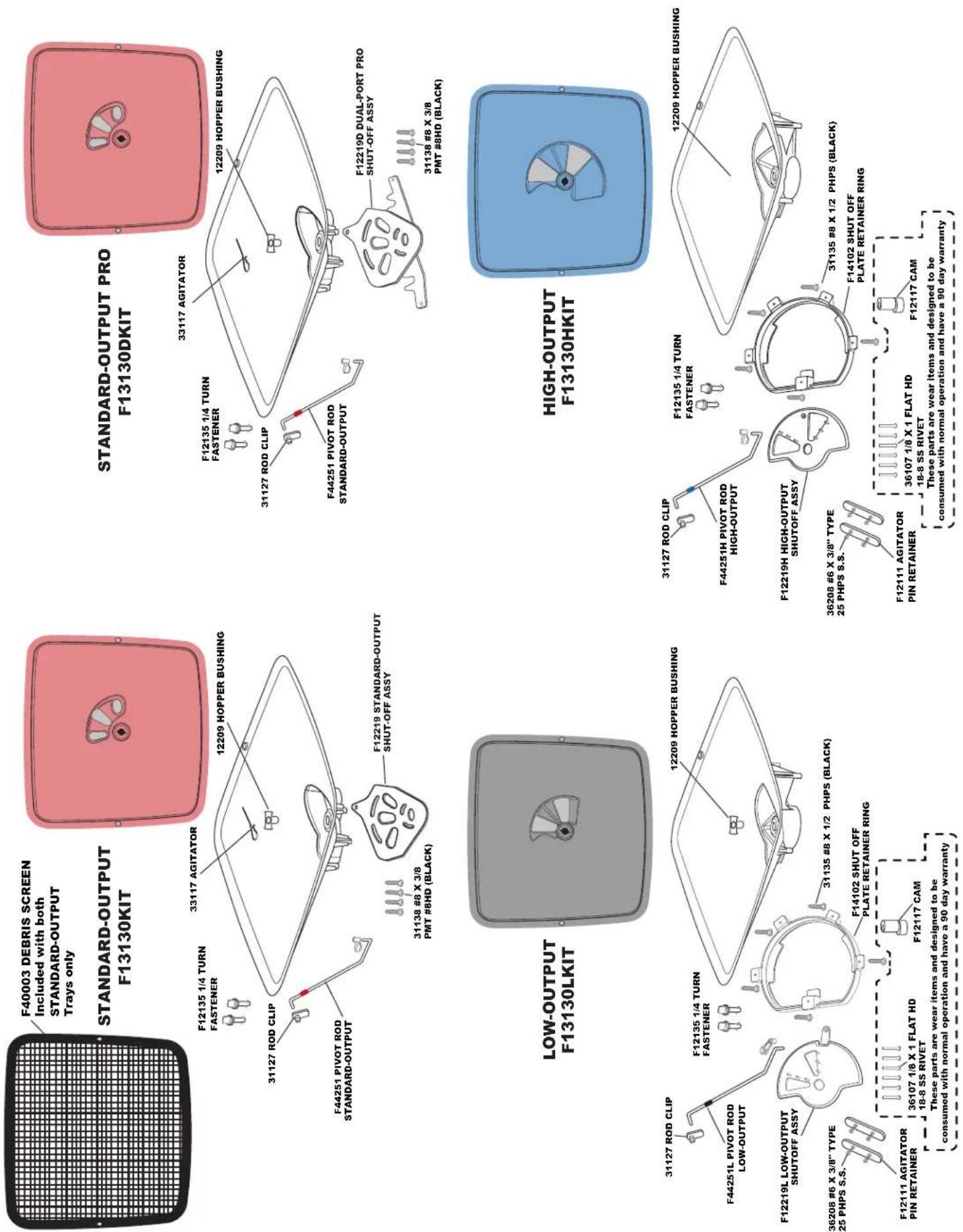
| Tray Options | 3 interchangeable: Standard-Output (Red), Low-Output (Black), High-Output (Blue) |
| Spreader Type | Broadcast, gear-driven, 13" pneumatic tire |
| Material Compatibility | Fertilizers, seed, ice melt, granular products |
| Spread Width | Up to 37 ft (11.3 m) depending on material and tray |
| Rate Control | Adjustable lever with stop settings (#0 to #30) |
| Adjustable Shut-Off System | EV-N-SPRED Dual Port PRO, left/right port adjustment for balanced spreading |
| Construction | Painted steel frame, poly hopper |
| Drive System | Gear-driven impeller (clockwise rotation), permanently lubricated gearbox |
| Assembly Required | Yes, tools: 7/16" wrench, ratchet with 7/16" socket, pliers |
| Maintenance | Clean after each use, apply light oil or silicon spray to prevent corrosion |
| Warranty | 5-year limited (original purchase receipt required) |
| Weight | Approx. 35 lbs (15.9 kg) |
| Supported Materials | Rock salt use requires daily removal to prevent gearbox damage |
| Spare Parts Availability | Order direct from EPI (574-848-7491) with model, part number, description |
| Technical Support | Lifetime support hotline: 800-294-0671, Mon-Fri 9am-4pm Eastern |
Frequently Asked Questions - S80 PRO Maruyama
User questions about S80 PRO Maruyama
0 question about this device. Answer the ones you know or ask your own.
Ask a new question about this device
Download the instructions for your Uncategorized in PDF format for free! Find your manual S80 PRO - Maruyama and take your electronic device back in hand. On this page are published all the documents necessary for the use of your device. S80 PRO by Maruyama.
USER MANUAL S80 PRO Maruyama
F80P & F130P FLEX-SELECT® Series
Adaptable Broadcast Spreader Assembly and Operating Instructions
PLEASE CONTACT US: IF YOU ARE MISSING ANY PARTS, HAVE ANY DIFFICULTY IN ASSEMBLY, OR HAVE ANY QUESTIONS REGARDING THE SAFE OPERATION OF THIS SPREADER. THIS MODEL INCLUDES LIFETIME TECHNICAL SUPPORT. SUPPORT HOT LINE: 800-294-0671
HELPFUL HINTS:
☑ If your spreader does not spread evenly, be sure the FRONT on the gear box points to the front of the spreader. The impeller must turn clockwise. Reversing the gearbox will cause the impeller to turn counter clockwise. Clean the impeller after each use as some fertilizer may become stuck on the impeller blades and will cause uneven spreading.
☑ Your spreader is designed to be pushed at three miles per hour, which is a brisk walking speed. Slower or faster speeds will change the spread patterns. Wet fertilizer will also change the spread pattern and flow rate.
√ Clean and dry your spreader thoroughly after each use, wash between the shut-off plate and bottom of the hopper regularly. To prevent rust, coat all metal parts (inside and out) including the frame tubes with a light oil, silicon spray, or Fluid Film®.
☑ Gears are permanently lubricated at the factory. Do not open the gearbox or dirt may enter.
When using Rock Salt to prevent damage to the gearbox remove salt from the hopper daily. Rock Salt will reconstitute back into a solid block if left in the hopper overnight and will damage your gearbox if pushed with the salt in place.
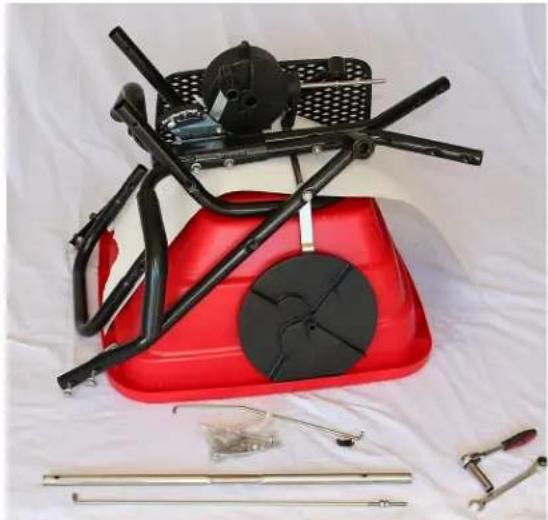
natural_image
Red bicycle seat with black frame and mechanical tools laid out on a white cloth (no text or symbols visible)WARNING
Do not use air tools to assemble.
To prevent seizing coat all bolts with a wax or grease prior to installation.
Remove all parts, hardware, and assemblies from carton and lay them out on the floor to help in assembly.
Below are tools needed for assembly - 7/16" wrench, ratchet and 7/16" socket, and pliers.
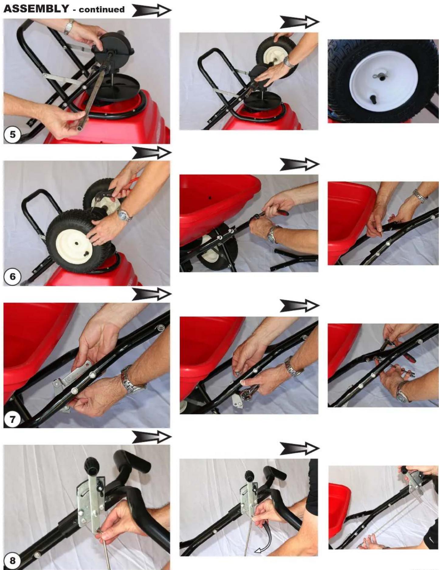
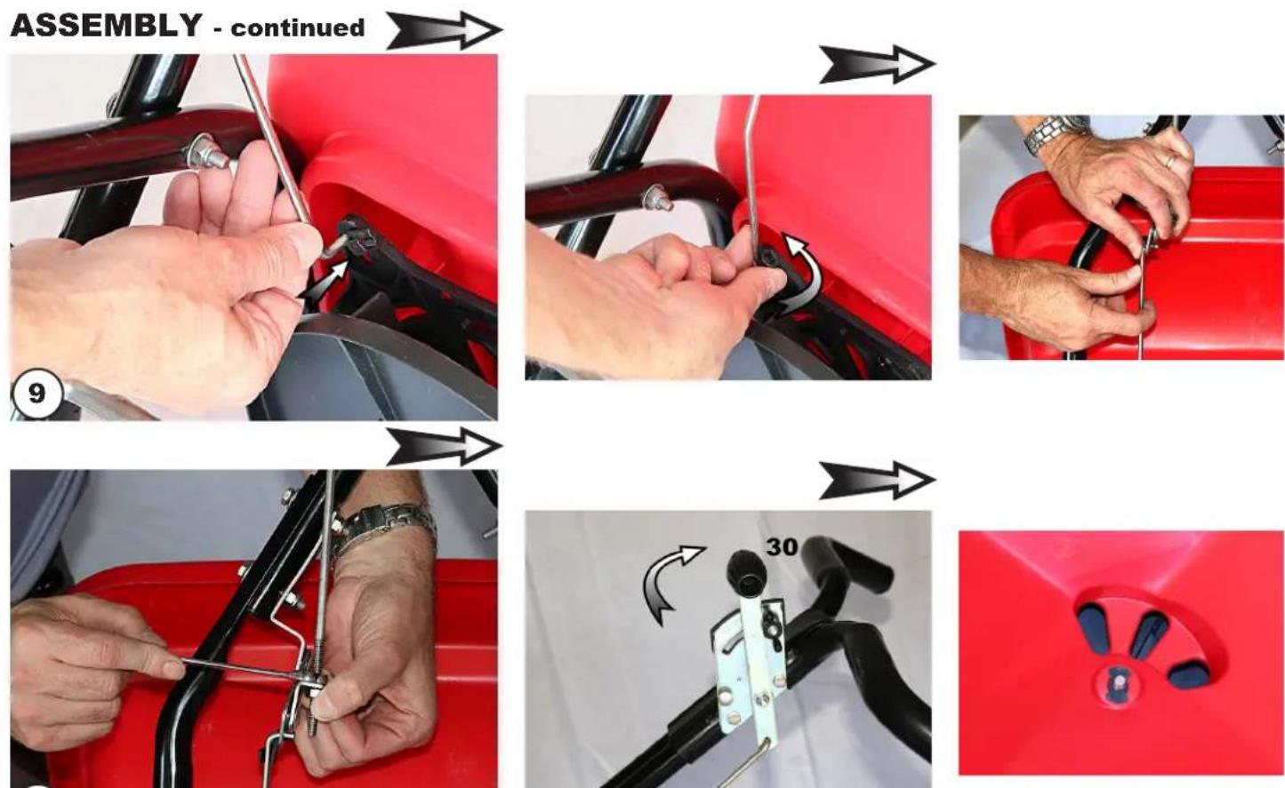
The following photos are for assembly purposes, and please follow them from left to right, top to bottom.
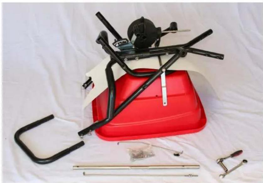
natural_image
Red bicycle seat with black frame and metal tools laid out on a white cloth (no text or symbols visible)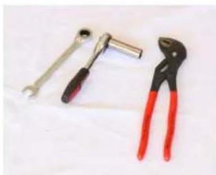
natural_image
Three hand tools: a wrench, a pliers, and a flat tool (no text or symbols visible)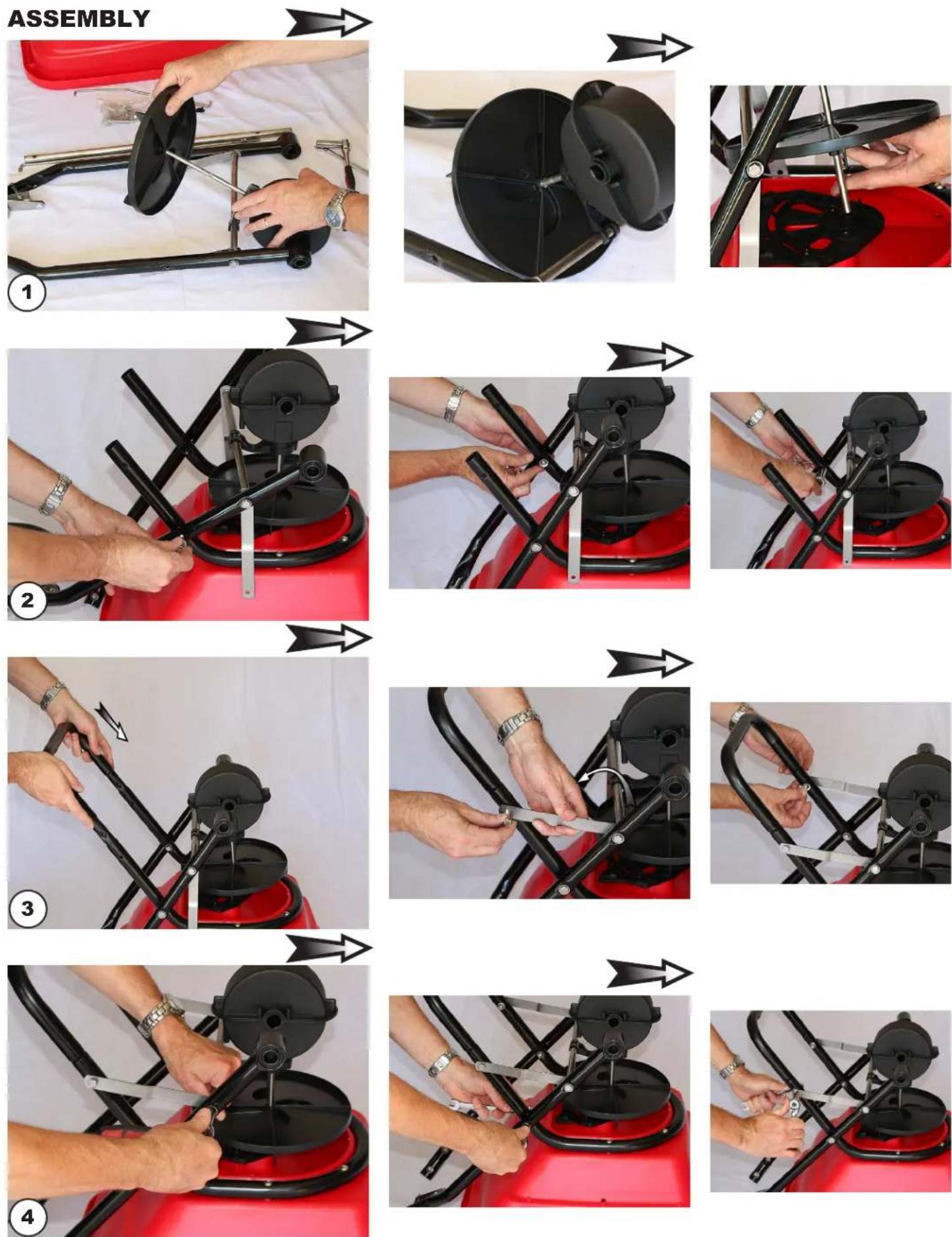
natural_image
Close-up of hands installing or adjusting a metal bracket on a red vehicle chassis (no text or symbols visible)CONFIRM THE CALIBRATION:
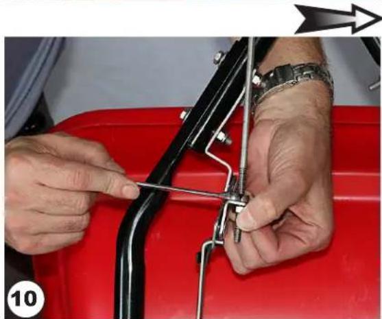
Lever at #30 and the drop holes fully open
TO COMPLETE ASSEMBLY:
Install Agitator, bend the Agitator up slightly to prevent contact with the STANDARD-OUTPUT tray, and install debris screen.
Press over 1/4 turn fasteners to secure.
This only applies to the RED 3-hole drop STANDARD-OUTPUT Trays.
The HIGH-OUTPUT (Blue) and LOW-OUTPUT (Black) Trays do not use the Agitator or Debris Screen shown below.
natural_image
Hand holding a key inserted into a red car vent (no text or symbols visible)
natural_image
Close-up of a hand holding a small mechanical component with a curved arrow indicating rotation (no text or symbols visible)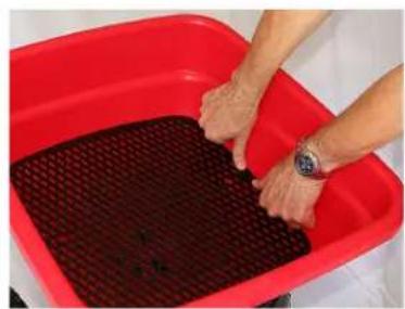
natural_image
Person washing a red plastic basin with dark material (no text or symbols visible)TRAY INSTALLATION
natural_image
Close-up of a red plastic bucket being handled by a hand, with a black vehicle and tire visible (no text or symbols)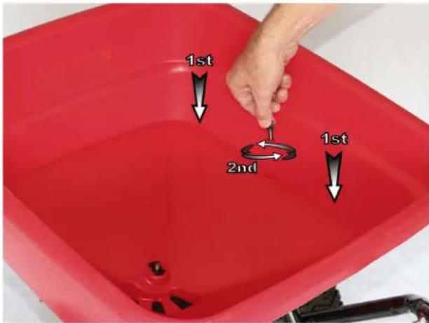
HIGH-OUTPUT AND LOW-OUTPUT: require the use of the Part #F12117
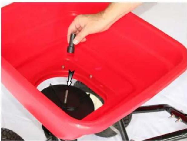
natural_image
Red plastic recycling bin with a hand pouring liquid into the container (no text or symbols visible)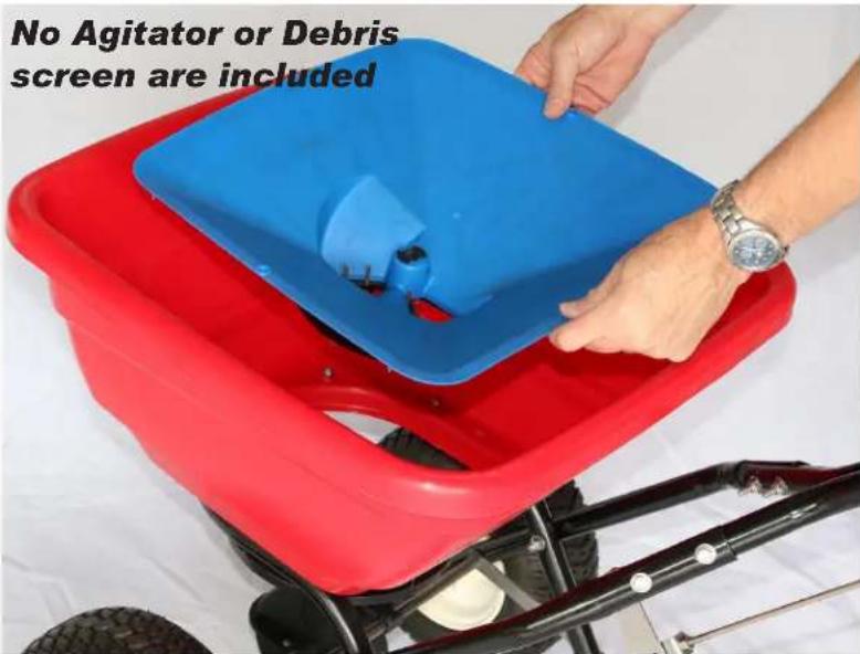
HIGH-OUTPUT AND LOW-OUTPUT: require the use of the Part #F12117
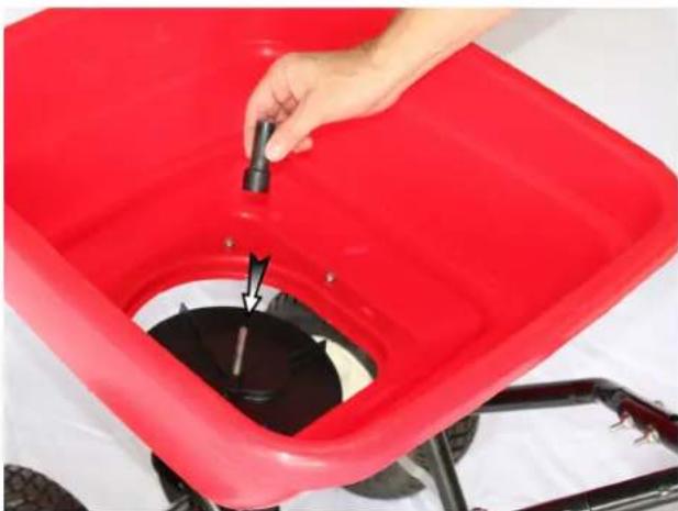
natural_image
Red plastic container with black liquid being inserted, held by a hand (no text or symbols visible)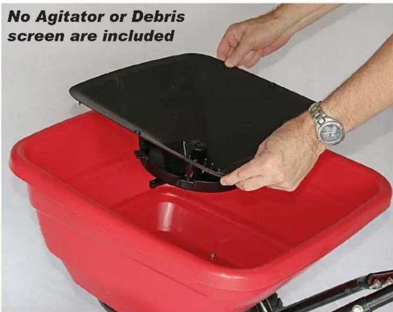
Flex-Select®
Setup and Calibration Techniques
How to Install a Tray
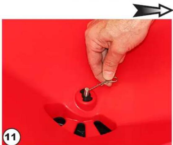
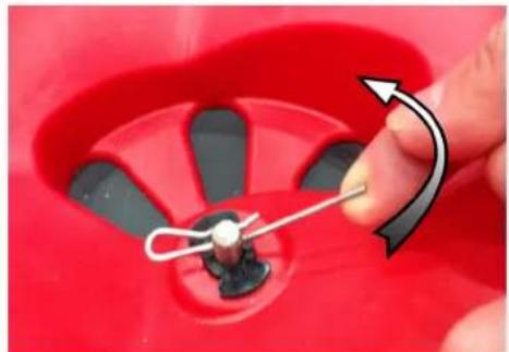
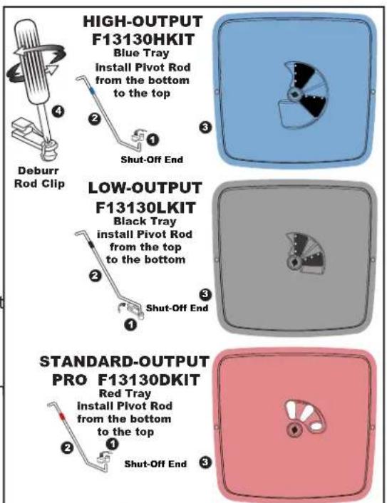
First ensure the hopper is clean and there is no debris trapped around the tray mounting area. Secondly install the Pivot Rod Clip① into the Shut-off of the selected Tray②. Next, insert the Pivot Rod② into the Clip①. TIP: The Clip① may have a burr in the hole, use a Phillips screwdriver to remove the burr.
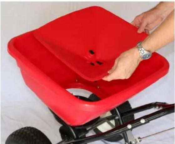
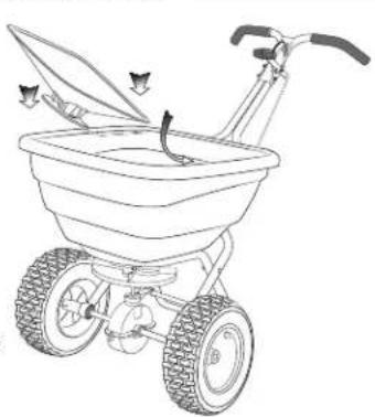
See④ to make installing the Pivot Rod② easier. Pliers may be required to help squeeze the Pivot Rod② into the Clip①. When the Rod② is secure inside the Clip① push the free end of the Clip① over the Pivot Rod② to firmly secure the rod to the clip. Next, install the Tray③ from the top downwards into the hopper (see figure⑤) positioning the center hole of the tray over the Pinion Shaft from the gear box with the Pivot Rod through the bottom of the hopper and facing toward the spreader's handlebar. For ease of locating into position the shut-off of the chosen tray is best in the open position, with the exception of the red
STANDARD-OUTPUT Tray where the two adjustable throwing ports are best in the closed position.
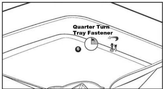
NOTE: The gearbox can be moved along the axle to ease aligning of the tray hole and the pinion shaft. Once the tray is in place check that the tray is sealed and flush against the hopper sides. To check if the tray is properly located, push the tray edges downwards. Install the two quarter turn fasteners (see figure⑥) through the two exposed tray holes and push down and twist a quarter turn to secure.
Lastly, connect the free end of the Pivot Rod into the Pivot linkage at the bottom of the Control Rod. Position the Clip into the free hole and push the
Pivot Rod ^2 into the clip. TIP: The Clip ^1 may have a burr in the hole, use a Phillips screwdriver to remove the burr (see figure ^4 ) When the Pivot Rod ^2 is positioned inside the Clip ^1 push the free end of the Clip ^1 over the Pivot Rod ^2 to firmly secure the rod and the clip together.
How to ensure your spreader is properly calibrated
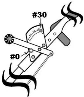
HIGH-OUTPUT and LOW-OUTPUT Trays: Make sure the drop holes in the bottom of the hopper are FULLY CLOSED when the Rate Control Lever is resting on the Stop #0. If the shut-off is not set correctly, please adjust Control Rod at the
Pivot to position the shut-off for FULLY CLOSED at position at the Stop #0 on the Rate Control Lever. As a side note, the HIGH-OUTPUT and LOW-OUTPUT Trays do not include or use a horizontal agitator.
Calibration Adjustment
Review the Control Lever position to confirm that it is set so that the forward edge of the Lever is resting at #0 (the stop) and the drop holes are closed. Move the spreader back & forth to ensure that the cam is positioned to allow the Oscillating Shut-off to close fully. If the shut-off is not properly positioned, you will need to adjust the Control Rod at the Pivot Bracket shown below.
TIP: If your shut-off is not able to CLOSE fully, loosen the top nut a few turns, then tighten the lower nut so that it allows you to push the shut-off fully closed. Next, tighten each nut so that they contact the pivot bracket without moving it, and then carefully tighten each nut fully so they do not loosen during use. Recheck adjustment as outlined above.
natural_image
Line drawing of a small wheeled cart with wheels and a handle, showing mechanical components (no text or symbols)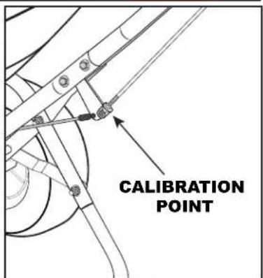
How to ensure your spreader is properly calibrated - continued
STANDARD-OUTPUT Tray: Make sure the drop holes in the bottom of the hopper are FULLY OPEN when the Rate Control handle is on #30. If the shut-off is not set correctly, please adjust Control Rod at the Pivot to position the shut-off for FULLY OPEN hopper position at #30 on the Rate Control Lever. Install the horizontal agitator through the pinion shaft in the hopper bottom. Finally, install the debris screen onto the Quarter-turn fasteners and push down to snap and secure.
Calibration Adjustment
Review the Control Lever position to confirm that it is set so that the rear edge of the Lever is resting at #30 (the stop) and the drop holes are open. If the shut-off is not properly positioned, you will need to adjust the Control Rod at the Pivot Bracket shown below. TIP: If your shut-off is not able to OPEN fully, loosen the bottom nut a few turns, then tighten the upper nut so that it allows you to push the shut-off fully open. Next, tighten each nut so that they contact the pivot bracket without moving it, and then carefully tighten each nut fully so they do not loosen during use. Recheck adjustment as outlined above.
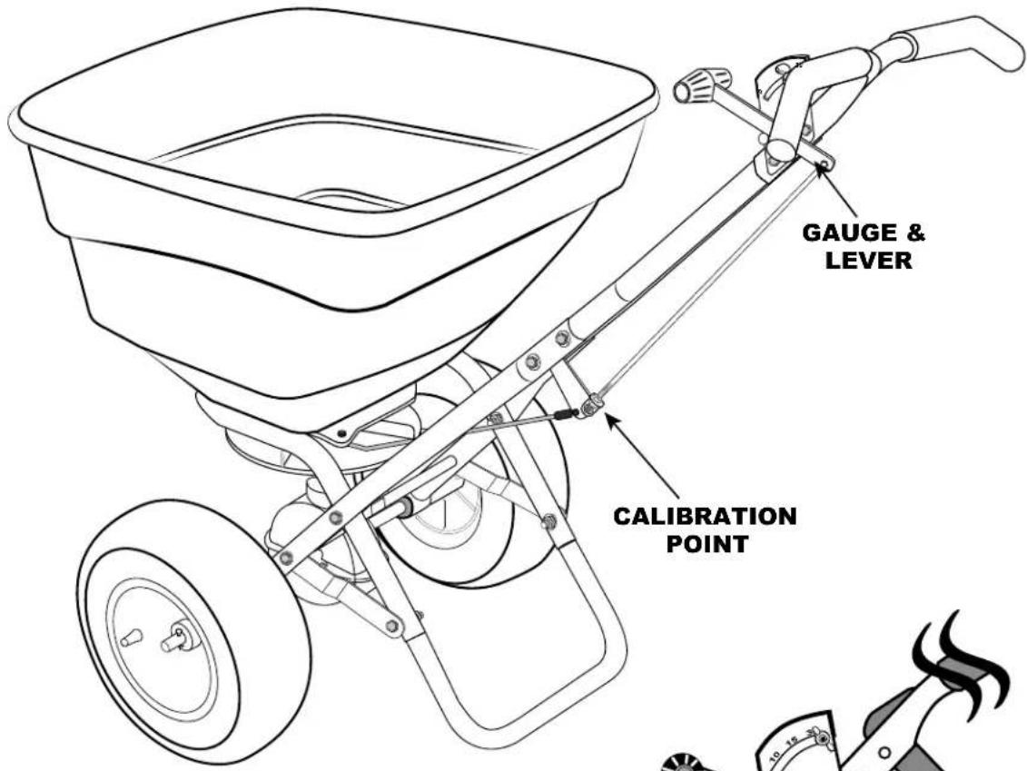
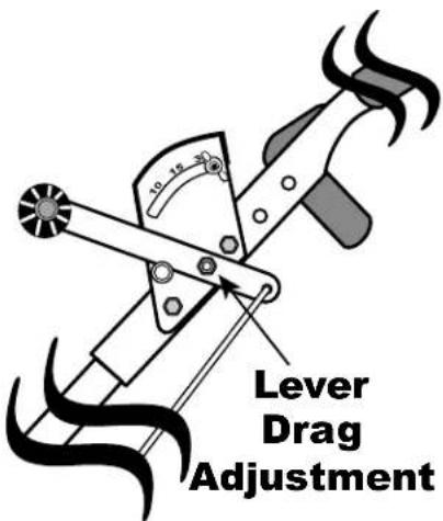
Control Lever Drag adjustment
If the Control Lever does not stay in position causing the setting rate to change without your intervention, you can adjust the drag on the Lever by tightening or loosening the nut shown to the right until the drag is appropriate.
If you have any questions regarding the assembly or safe operation your spreader, please contact us at 800-294-0671 or 574-848-7491 Monday - Friday 9:00am - 4:00pm Eastern.
Using the EV-N-SPRED® Dual Port PRO Adjustable Shut-Off System
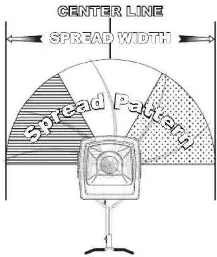
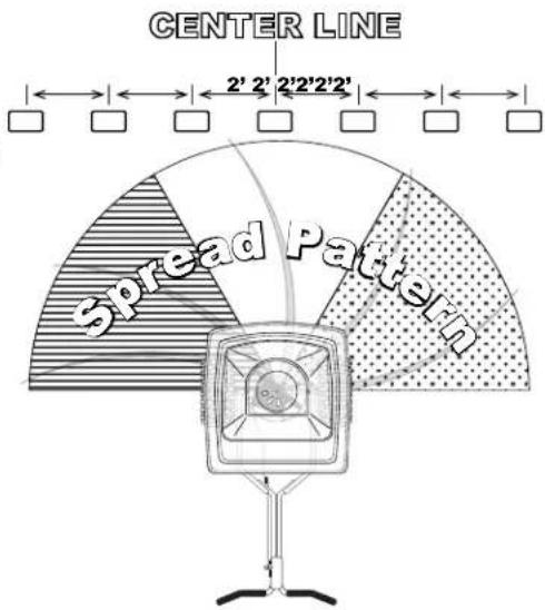
The EV-N-SPRED® Dual Port PRO Adjustable Shut-Off System is included on all professional models and allows the operator to balance the spread pattern evenly across the full 180° spread width, regardless of the weight or size of granular material. By closing either the right and or left side throwing ports you can balance the spread pattern to exacting precision without compromising spread width or application rate.
Each EV-N-SPRED® Dual Port PRO Adjustable Shut-Off System drop hole has a corresponding 1/3^rd coverage area on the spread width of the spreader leaving a feathered-edge for overlapping the spread path. The illustration to the right shows each port and the corresponding 1/3^rd coverage area of the spread path. These ports can be adjusted to effectively balance the sp pattern, giving equal amounts of material across the full 1 spread pattern.
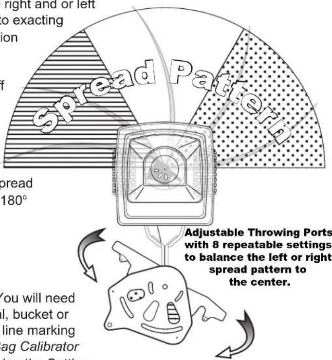
EV-N-SPRED®Dual Port PRO System Setup
Test all material prior to beginning your spreading job. You will need a 50' measuring tape, a small scale to weigh the material, bucket or container to hold the material for re-weighing, chalk or a line marking device, and (7) low baking tins. Using the EarthWay® Bag Calibrator #77016 can greatly reduce the time needed for determining the Setting Rates on any material but is not mandatory to establish a setting rate.
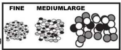
- Evaluate the material being spread by comparing it to the following standard as a reference.
Large/Heavy is the size of a BB ( 18 in / 3mm), spread width is 28 - 36 feet (8.5 - 11 meters)
Medium/Mixed ( 12 the size of a BB), spread width is 20 - 24 feet (6.1 - 7.3 meters)
Small/Fine (the size of sand), spread width is 16 - 18 feet (4.8 - 5.5 meters)
- Add a small amount of the material into the spreader, enough to cover the bottom (2-3 in / 5 - 7 cm) and begin to test for spread width.
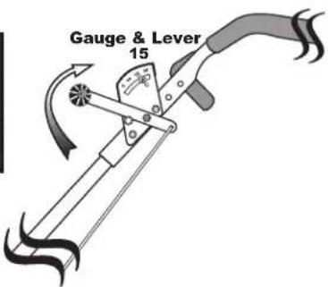
Set the stop on the gauge to #15 and push the spreader several feet / meters at normal walking speed on a flat hard surface (where the material will be visible), and OPEN the lever to the STOP while continuing to walk for 3-4 paces, and CLOSE the shut-off and STOP (don't move the spreader from that position). Measure the spread width and evaluate the spread pattern for even distribution on either side of the spread width center line. TIP: Typical spread width references are listed above. The spread width that you measure is used to calculate the actual Setting Rate for the material.
ADJUSTING THE EV-N-SPRED® DUAL PORT SHUT-OFF SYSTEM
Next, using the (7) low baking tins position, them in a straight line on 2-foot centers across the spread width as shown at the right.
Adjust the left or right variable throwing ports to EVEN THE SPREAD pattern.
TIP: For large/heavy materials, close the LEFT SIDE (LINES) port slightly before you start your EV-N-SPRED® test. For small/light materials, open the
LEFT SIDE (LINES) port fully and close the RIGHT SIDE (CIRCLES) port slightly before you start your EV-N-SPRED® test. With BOTH ports closed, the spread is only from the center port, and will give you a 3-4ft spread width in the center of the spreader - great for medians. Begin pushing the spreader several feet before the line of tins and at normal walking speed.
Walk along the Center Line, and OPEN the Lever to the STOP 3-4 paces before the line of tins and continue walking past the tins 1 or 2 paces and CLOSE the Lever and STOP.
Visually evaluate the material in the baking tins to determine if your spread pattern is balanced - having the same amount of material in each baking tin.
Empty each tin back into the spreader, adjust the ports and RETEST until you are satisfied that the coverage is balanced.
| Spread width in feet | Length needed for 1,000 Sq Ft | Spread width in feet | Length needed for 1,000 Sq Ft | Spread width in feet | Length needed for 1,000 Sq Ft |
| 7 142' 10" | 17 58' 10" | 37' | |||
| 8 | 125' | 18 | 55' 7" | 28 | 35' 9" |
| 9 | 111' 1" | 19 | 52' 7" | 29 | 34' 6" |
| 10 | 100' | 20 | 50' | 30 | 33' 4" |
| 11 | 90' 11" | 21 | 47' 7" | 31 | 32' 3' |
| 12 | 83' 4" | 22 | 45' 5" | 32 | 31' 3" |
| 13 | 76' 11" | 23 | 43' 6" | 33 | 30' 4" |
| 14 | 71' 5" | 24 | 41' 8" | 34 | 29' 5" |
| 15 | 66' 8" | 25 | 40' | 35 | 28' 7" |
| 16 | 62' 6" | 26 | 38' 6" | 36 | 27' 9" |

natural_image
Two identical cartoon-style black-and-white face masks with striped designs, no text or symbols present.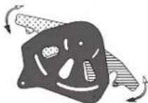
ESTABLISH THE SETTING RATE
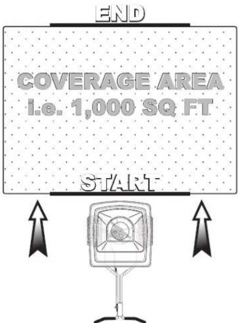
Remove the material from the hopper, and mark the distance that you need to travel with the spreader to attain the designated coverage area - i.e. 1,000 square feet using the spread width you determined earlier. Above is a chart to help determine the distance needed for 1,000 square foot calculation.
Mark the START and END POINTS on the surface required for the test. Weigh a small amount (10-20lbs/4-9kg) of the material, and add that into to the spreader. Using the Setting Matrix included with the spreader, estimate a setting rate based on material manufacturers recommendations and adjust the STOP on the Gauge to that position.
Now to test, start walking 1-2 paces before the START LINE and OPEN the Lever to the stop and then CLOSE when you cross the END POINT LINE.
Pour the remaining material from the spreader and weigh to calculate the amount applied over the area. Adjust the Setting Rate to a higher number if you need to increase the application rate, or to a lower number if you applied too much in the test.
You may need to repeat this process to acquire the exact rate.
The EV-N-SPRED® Dual Port PRO Adjustable Shut-Off System ensures that EarthWay® Professional spreaders evenly spread all types of fertilizers, seed, ice melt, or other granular products, and is only available from EarthWay®.
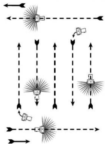
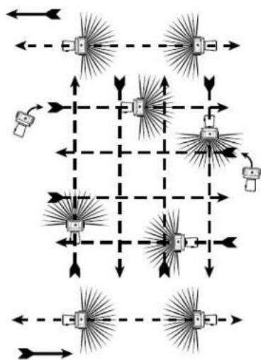
SPREAD PATH
FULL Rate (one pass)
flowchart
graph TD
    A["Input"] --> B["Signal"]
    B --> C{Decision}
    C -->|Yes| D["Output 1"]
    C -->|No| E["Output 2"]
    D --> F["Output 3"]
    E --> G["Output 4"]
    F --> H["Output 5"]
    G --> H
    H --> I["Output 6"]
    I --> J["Output 7"]
    J --> K["Output 8"]
    K --> L["Output 9"]
    L --> M["Output 10"]
    M --> N["Output 11"]
    N --> O["Output 12"]
    O --> P["Output 13"]
    P --> Q["Output 14"]
    Q --> R["Output 15"]
    R --> S["Output 16"]
    S --> T["Output 17"]
    T --> U["Output 18"]
    U --> V["Output 19"]
    V --> W["Output 20"]
    W --> X["Output 21"]
    X --> Y["Output 22"]
    Y --> Z["Output 23"]
    Z --> AA["Output 24"]
    AA --> AB["Output 25"]
    AB --> AC["Output 26"]
    AC --> AD["Output 27"]
    AD --> AE["Output 28"]
    AE --> AF["Output 29"]
    AF --> AG["Output 30"]
    AG --> AH["Output 31"]
    AH --> AI["Output 32"]
    AI --> AJ["Output 33"]
    AJ --> AK["Output 34"]
    AK --> AL["Output 35"]
    AL --> AM["Output 36"]
    AM --> AN["Output 37"]
    AN --> AO["Output 38"]
    AO --> AP["Output 39"]
    AP --> AQ["Output 40"]
    AQ --> AR["Output 41"]
    AR --> AS["Output 42"]
    AS --> AT["Output 43"]
    AT --> AU["Output 44"]
    AU --> AV["Output 45"]
    AV --> AW["Output 46"]
    AW --> AX["Output 47"]
    AX --> AY["Output 48"]
    AY --> AZ["Output 49"]
    AZ --> BA["Output 50"]
    BA --> BB["Output 51"]
    BB --> BC["Output 52"]
    BC --> BD["Output 53"]
    BD --> BE["Output 54"]
    BE --> BF["Output 55"]
    BF --> BG["Output 56"]
    BG --> BH["Output 57"]
    BH --> BI["Output 58"]
    BI --> BJ["Output 59"]
    BJ --> BK["Output 60"]
    BK --> BL["Output 61"]
    BL --> BM["Output 62"]
    BM --> BN["Output 63"]
    BN --> BO["Output 64"]
    BO --> BP["Output 65"]
    BP --> BQ["Output 66"]
    BQ --> BR["Output 67"]
    BR --> BS["Output 68"]
    BS --> BT["Output 69"]
    BT --> BU["Output 70"]
    BU --> BV["Output 71"]
    BV --> BW["Output 72"]
    BW --> BX["Output 73"]
    BX --> BY["Output 74"]
    BY --> BZ["Output 75"]
HALF Rate (two passes)
flowchart
graph TD
    A["Input Node 1"] --> B["Node 1"]
    C["Input Node 2"] --> D["Node 2"]
    E["Input Node 3"] --> F["Node 3"]
    G["Input Node 4"] --> H["Node 4"]
    I["Input Node 5"] --> J["Node 5"]
    K["Input Node 6"] --> L["Node 6"]
    M["Input Node 7"] --> N["Node 7"]
    O["Input Node 8"] --> P["Node 8"]
    Q["Input Node 9"] --> R["Node 9"]
    S["Input Node 10"] --> T["Node 10"]
    U["Input Node 11"] --> V["Node 11"]
    W["Input Node 12"] --> X["Node 12"]
    Y["Input Node 13"] --> Z["Node 13"]
    AA["Input Node 14"] --> AB["Node 14"]
    AC["Input Node 15"] --> AD["Node 15"]
    AE["Input Node 16"] --> AF["Node 16"]
    AG["Input Node 17"] --> AH["Node 17"]
    AI["Input Node 18"] --> AJ["Node 18"]
    AK["Input Node 19"] --> AL["Node 19"]
    AM["Input Node 20"] --> AN["Node 20"]
△ = - + 1 + 1
5-YEAR LIMITED WARRANTY
EPI warrants this product free of defects in original workmanship and materials for a period of 5-Years to the end user with the original purchase receipt. If a manufacturing non-conformance is found, EPI at its discretion will repair or replace the part(s) or product at no charge provided the failure is not the result of incorrect installation, mishandling, misuse, tampering, or normal wear and tear as determined by EPI. EPI at its discretion may require that the part(s) or product be returned along with the original purchase receipt at owners' expense for examination and compliance with the terms of this warranty. Do not return any product without first receiving authorization from EPI. To seek remedy under this warranty, contact EPI at 574-848-7491, or write to EPI P.O. Box 547 Bristol, Indiana 46507 and describe the nature of the manufacturing defect. SPECIFIC LIMITATIONS: This warranty covers only the part(s) or product; any labor charges associated with repair or replacement of non-conformances are specifically excluded. Due to the corrosive nature of most fertilizers and ice melt products, EPI makes no warranty against and specifically excludes part(s) or product degradation or failure due to corrosion or its effects. Clean and dry your spreader thoroughly after each use, as a preventative measure, coat all metal parts with a light oil or silicon spray.
OPERATING INSTRUCTIONS
Before filling hopper, become familiar with the operation of this spreader.
☑ Obtain proper setting for material to be used from the enclosed SETTING MATRIX included with this spreader, or from our web site under the MANUALS SECTION.
☑ Move stop bolt on rate gauge assembly to the proper setting.
☑ While pushing spreader forward, pull control lever back to stop bolt.
☑ To stop, push lever forward to close flow holes before you stop moving.
☑ When finished, empty any remaining material from hopper.
☑ Thoroughly wash spreader and allow to dry before storing. Apply coating of light oil to help prevent corrosion.
☑ If you use Rock Salt, remove agitator when using Rock Salt to prevent damage to the gearbox.
EPI
1009 Maple Street, PO Box 547
Bristol, IN 46507
For Your Records
Date Purchased
Place of Purchase
HOW TO ORDER SPARE PARTS
All spare parts listed may be ordered direct from EPI
Be sure to give the following information when ordering.
Model Number
Part Number
Part Description
Call (574) 848-7491
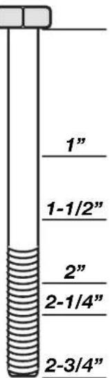
Bolt Identifier
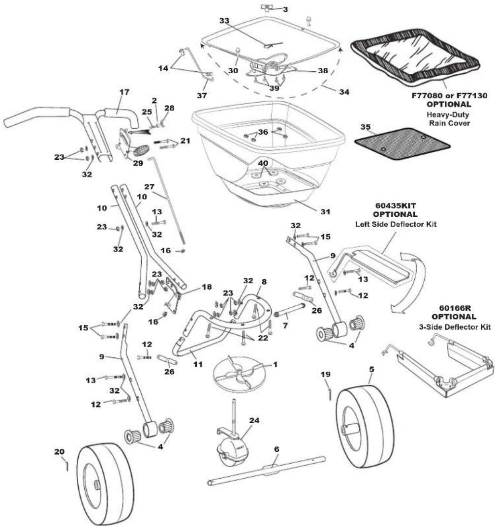
F80P & F130P Series Professional Broadcast Spreader
Key # Part # Description Key # Part # Description
| 1 121 | 0 IMPELLE | R 9" ROUND DISHED | 23 3210 | 3 1/4-20 NYLON INS LOCKNUT ZINC | |
| 2 | 12147 | SPACER (PIVOT LINK) | 24 | F60333 | GEAR BOX ASSEMBLY FLEX -SELECT |
| 3 | 12209 | HOPPER BUSHING | 25 | 37100 | 1/4-20 X 1" CARRIAGE BOLT ZINC |
| 4 | 12352 | BEARING (COMMERCIAL) EACH | 26 | 42237 | FRAME BRACE |
| 5 | 19117 | 13" DIA PNEU TIRE DRIVE | 27 | 42256 | CONTROL ROD |
| 6 | 24500 | AXLE, COINED | 28 | 60027 | WING NUT ASSEMBLY BLACK |
| 7 | 24704 | CROSS BRACE (11.125") | 29 | 60298 | GAUGE & LEVER ASSEMBLY |
| 8 | 25108 | FRAME | 30 | F12135 | 1/4 TURN FASTENER FLEX SELECT |
| 9 | 25202 | LOWER HANDLE COMPLETE | 31 | FLEX-SELECT 80# HOPPER (F13105) 130# HOPPER (F13106) | |
| 10 | 25301 | HANDLE SHAFT | 32 | 36404 | 1/4 CUPPED WASHER S.S. |
| 11 | 25723 | FRAME Foot (Flex-Select Painted) | 33 | 33117 | AGITATOR |
| 12 | 31100 | 1/4-20 X 1 1/2 HHMS ZINC | 34 | F13130D | STANDARD OUTPUT DUAL PORT PRO FLEX-SELECT TRAY KIT |
| 13 | 31106 | 1/4-20 X 2 1/4" HHCS ZINC | 35 | F40003 | SQUARE SCREEN FLEX-SELECT |
| 14 | 31127 | ROD CLIP (Flex-Select) | 36 | 36300 | 1/4-20 NYLON INSERT LOCKNUT S.S. |
| 15 | 31114 | 1/4-20 X 1 3/4" HHCS ZINC | 37 | F44251 | PIVOT ROD STD OUTPUT FLEX-SELECT |
| 16 | 36305 | 1/4-20 HEX NUT STAINLESS STEEL | 38 | F12219D | DUAL PORT PRO FLEX-SELECT SHUTOFF ASSEMBLY |
| 17 | 60069 | UPPER HANDLE ASSEMBLY W/GRIPS | 39 | 31138 | #8 X 3/8" PMT #8 HD COARSE BLACK |
| 18 | 60299 | PIVOT & BRACKET ASSEMBLY | 40 | 43020 | BACKPLATE WASHER |
| 19 | 36103 | 3/16 X 2" COTTER PIN S.S. | Optional | 60435KIT | SIDE DEFLECTOR |
| 20 | 36104 | 3/16 X 1" COTTER PIN S.S. | Optional | HEAVY DUTY RAIN COVER (F77080 for F80 / F77130 FOR F130) | |
| 21 | 31107 | 1/4-20 X 2 3/4" HHCS ZINC | Optional | 12195 | GAUGE OVERLAY- LESCO SETTINGS |
| 22 | 36214 | 1/4-20 X 1 1/2" PHPMS S.S. | Standard | 12196RT | GAUGE OVERLAY- RT |
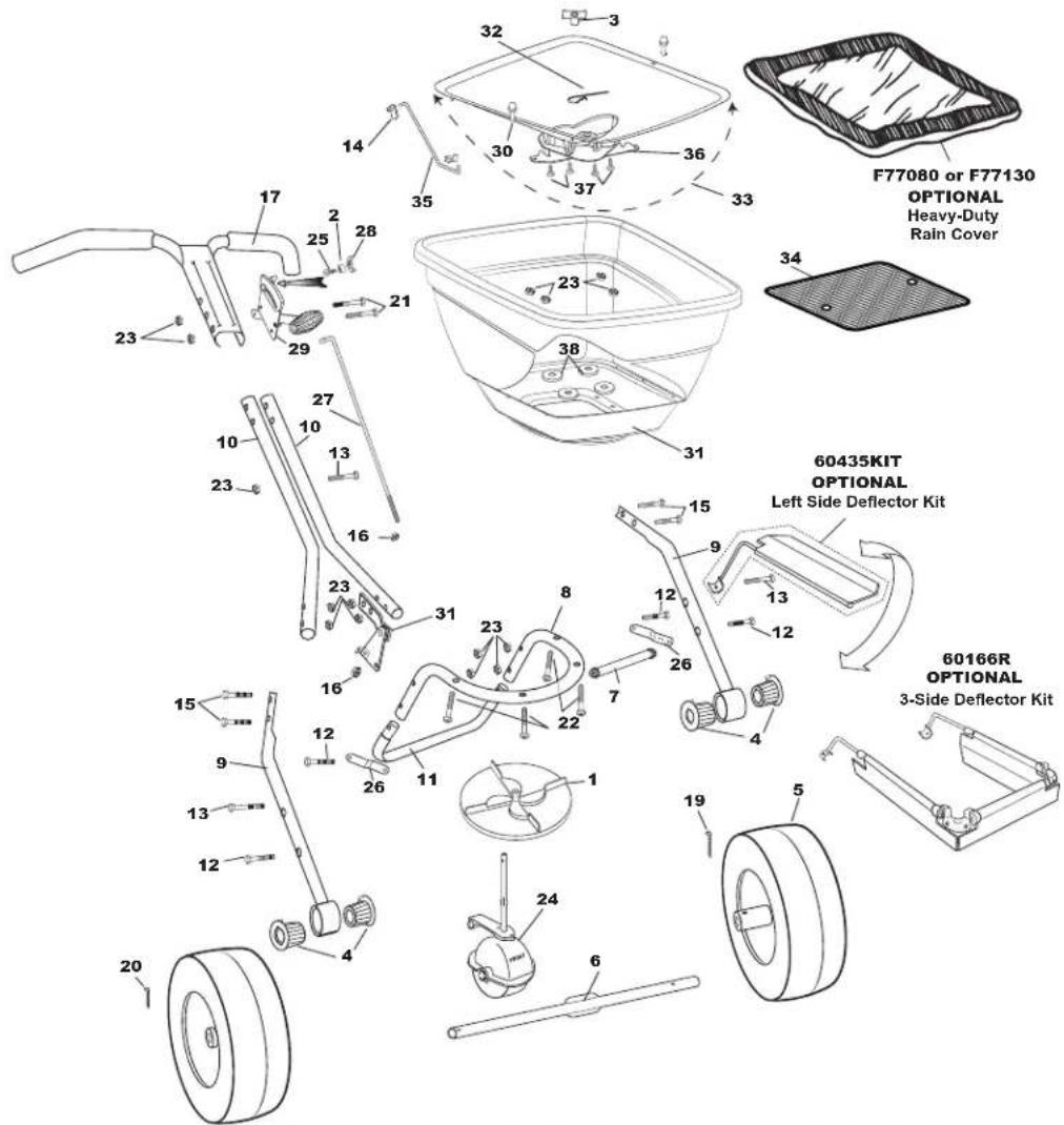
| F80PS & F130PS Series Professional Broadcast SpreaderKey # Part # Description Key # Part # Description | |||||
| 1 121 | 0 IMPELLE | R 9" ROUND DISHED | 22 362 | 4 1/4-20 X 1 | 1/2" PHPMS S.S. |
| 2 1214 | 7 SPACER | (PIVOT LINK) 23 36300 1/4-20 NYLON INSERT LOCKNUT | S.S. | ||
| 3 | 12209 | HOPPER BUSHING | 24 | F60333 | GEAR BOX ASSEMBLY FLEX -SELECT |
| 4 | 12352 | BEARING (COMMERCIAL) EACH | 25 | 37100 | 1/4-20 X 1" CARRIAGE BOLT ZINC |
| 5 | 19117 | 13" DIA PNEU TIRE DRIVE | 26 | 42237 | FRAME BRACE |
| 6 | 24500 | AXLE, COINED | 27 | 42256 | CONTROL ROD |
| 7 | 24704 | CROSS BRACE (11.125") | 28 | 60027 | WING NUT ASSEMBLY BLACK |
| 8 | 24111 | FRAME | 29 | 60298 | GAUGE & LEVER ASSEMBLY |
| 9 | 24202 | LOWER HANDLE COMPLETE | 30 | F12135 | 1/4 TURN FASTENER FLEX SELECT |
| 10 | 24300 | HANDLE SHAFT | 31 | FLEX-SELECT 80# HOPPER (F13105) 130# HOPPER (F13106) | |
| 11 | 25723-SS | FRAME FOOT SS | 32 | 33117 | AGITATOR |
| 12 | 36200 | 1/4-20 X 1 1/2" HHCS S.S. | 33 | F13130D | STANDARD OUTPUT DUAL PORT PRO FLEX-SELECT TRAY KIT |
| 13 | 36205 | 1/4-20 X 2 1/4" HHCS S.S. | 34 | F40003 | SQUARE SCREEN FLEX-SELECT |
| 14 | 31127 | ROD CLIP (Flex-Select) | 35 | F44251 | PIVOT ROD STD OUTPUT FLEX-SELECT |
| 15 | 36209 | 1/4-20 X 1 3/4" HHCS S.S. | 36 | F12219D | DUAL PORT PRO FLEX-SELECT SHUTOFF ASSEMBLY |
| 16 | 36305 | 1/4-20 HEX NUT STAINLESS STEEL | 37 | 31138 | #8 X 3/8" PMT #8 HD COARSE BLACK |
| 17 | 60070 | UPPER HANDLE ASSEMBLY W/GRIPS | 38 | 43020 | BACKPLATE WASHER |
| 18 | 60299 | PIVOT & BRACKET ASSEMBLY | |||
| 19 | 36103 | 3/16 X 2" COTTER PIN S.S. | Optional | 60435KIT | SIDE DEFLECTOR |
| 20 | 36104 | 3/16 X 1" COTTER PIN S.S. | Optional | HEAVY DUTY RAIN COVER (F77080 for F80 / F77130 FOR F130) | |
| 21 | 36207 | 1/4-20 X 2 3/4" HHCS S.S. | Optional | 12195 | GAUGE OVERLAY- LESCO SETTINGS |
| 22 | 36214 | 1/4-20 X 1 1/2" PHPMS S.S. | Standard | 12196RT | GAUGE OVERLAY- RT |
FLEX-SELECT® BROADCAST SPREADER SETTING MATRIX
GRANULAR MATERIAL
Standard-Output Red Tray
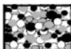
PARTICLE SIZES: Fine/Small →
(SAND) (HALF BB) (BB) ROCK
Grams PER Square
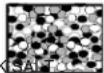
Medium →
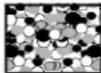
Large →
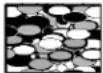
EXTRA LARGE →

SPREAD SPREAD SPREAD SPREAD SPREAD SPREAD SPREAD
| Meter | SETTING | WIDTH FT | METERS | SETTING | WIDTH FT | METERS | SETTING | WIDTH FT | METERS | SETTING | WIDTH FT | METERS |
| 5 | 7 | 18 | 5.5 | 9 | 24 | 7.3 | 14 | 36 | 11.0 | 17 | 37 | 11.3 |
| 10 | 10 | 18 | 5.5 | 13 | 24 | 7.3 | 18 | 36 | 11.0 | 22 | 37 | 11.3 |
| 15 | 13 | 18 | 5.5 | 16 | 24 | 7.3 | 23 | 36 | 11.0 | 24 | 37 | 11.3 |
| 20 | 14 | 18 | 5.5 | 20 | 24 | 7.3 | 27 | 36 | 11.0 | 26 | 37 | 11.3 |
| 24 | 16 | 18 | 5.5 | 22 | 24 | 7.3 | 30 | 36 | 11.0 | 28 | 37 | 11.3 |
| 29 | 18 | 18 | 5.5 | 25 | 24 | 7.3 | 23 x 2 pass | 36 | 11.0 | 29 | 37 | 11.3 |
| 34 | 20 | 18 | 5.5 | 27 | 24 | 7.3 | 25 x 2 pass | 36 | 11.0 | 30 | 37 | 11.3 |
| 39 | 22 | 18 | 5.5 | 28 | 24 | 7.3 | 27 x 2 pass | 36 | 11.0 | 26 x 2 pass | 37 | 11.3 |
| 44 | 24 | 18 | 5.5 | 30 | 24 | 7.3 | 28 x 2 pass | 36 | 11.0 | 27 x 2 pass | 37 | 11.3 |
| 49 | 26 | 18 | 5.5 | 22 x 2 pass | 24 | 7.3 | 30 x 2 pass | 36 | 11.0 | 28 x 2 pass | 37 | 11.3 |
GRASS SEED


| Grams PER Square Meter | FINE SETTING | SPREAD WIDTH | SPREAD FT METERS | COARSE SETTING | SPREAD WIDTH | SPREAD FT METERS |
| 10 | 14 | 8 | 2.4 | 22 | 14 | 4.3 |
| 15 | 16 | 8 | 2.4 | 25 | 14 | 4.3 |
| 20 | 18 | 8 | 2.4 | 28 | 14 | 4.3 |
| 25 | 20 | 8 | 2.4 | 30 | 14 | 4.3 |
Calibration: Start by ensuring that your spreader calibration is correct. Make sure the drop holes in the Standard-Output Tray are fully open when the Rate Control handle is on #30. If not, please adjust control rod at the pivot to allow for a full open hopper holes with the handle at position at #30.
GRANULAR MATERIAL
Low-Output Black Tray
PARTICLE SIZES: Fine/Small →
(SAND) (HALF BB) (BB) ROCK
Grams PER Square
Meter
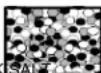
Medium →
Large →

EXTRA LARGE →

SPREAD SPREAD
SETTING WIDTH FT METERS
| 5 | 8 | 16 | 4.9 | 10 | 20 | 6.1 | 15 | 30 | 9.1 | 18 | 24 | 7.3 |
| 10 | 10 | 16 | 4.9 | 13 | 20 | 6.1 | 18 | 30 | 9.1 | 20 | 24 | 7.3 |
| 15 | 12 | 16 | 4.9 | 18 | 20 | 6.1 | 23 | 30 | 9.1 | 25 | 24 | 7.3 |
| 20 | 13 | 16 | 4.9 | 20 | 20 | 6.1 | 28 | 30 | 9.1 | 27 | 24 | 7.3 |
| 24 | 16 | 16 | 4.9 | 22 | 20 | 6.1 | 30 | 30 | 9.1 | 30 | 24 | 7.3 |
| 29 | 18 | 16 | 4.9 | 25 | 20 | 6.1 | 23 x 2 pass | 30 | 9.1 | 25 x 2 pass | 24 | 7.3 |
| 34 | 20 | 16 | 4.9 | 27 | 20 | 6.1 | 25 x 2 pass | 30 | 9.1 | 26 x 2 pass | 24 | 7.3 |
| 39 | 21 | 16 | 4.9 | 29 | 20 | 6.1 | 28 x 2 pass | 30 | 9.1 | 27 x 2 pass | 24 | 7.3 |
| 44 | 23 | 16 | 4.9 | 30 | 20 | 6.1 | 29 x 2 pass | 30 | 9.1 | 29 x 2 pass | 24 | 7.3 |
| 49 | 24 | 16 | 4.9 | 22 x 2 pass | 20 | 6.1 | 30 x 2 pass | 30 | 9.1 | 30 x 2 pass | 24 | 7.3 |
GRASS SEED


| Grams PER Square Meter | FINE SETTING | SPREAD WIDTH | SPREAD FT METERS | COARSE SETTING | SPREAD WIDTH | SPREAD FT METERS |
| 10 | 15 | 9 | 2.7 | 21 | 15 | 4.6 |
| 15 | 18 | 9 | 2.7 | 24 | 15 | 4.6 |
| 20 | 21 | 9 | 2.7 | 27 | 15 | 4.6 |
| 25 | 24 | 9 | 2.7 | 30 | 15 | 4.6 |
Calibration: Start by ensuring that your spreader calibration is correct. Make sure the drop holes in the LOW-OUTPUT TRAY are fully closed when the Rate Control Handle is resting on the stop #0. If not, please adjust control rod at the pivot to ensure the shut-off is fully closed with the handle at position at #0. Move the spreader slightly to confirm the calibration because of the cam.
GRANULAR MATERIAL
High-Output Blue Tray
PARTICLE SIZES: Fine/Small →
(SAND) (HALF BB) (BB) ROCK
Grams PER Square
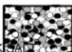
Medium →
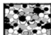
Large →
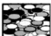
EXTRA LARGE →

SPREAD SPREAD SPREAD SPREAD SPREAD SPREAD SPREAD
| Meter | SETTING | WIDTH FT | METERS | SETTING | WIDTH FT | METERS | SETTING | WIDTH FT | METERS | SETTING | WIDTH FT | METERS |
| 5 | 3 | 16 | 4.9 | 5 | 22 | 6.7 | 7 | 28 | 8.5 | 8 | 26 | 7.9 |
| 10 | 5 | 16 | 4.9 | 6 | 22 | 6.7 | 10 | 28 | 8.5 | 11 | 26 | 7.9 |
| 15 | 6 | 16 | 4.9 | 8 | 22 | 6.7 | 12 | 28 | 8.5 | 13 | 26 | 7.9 |
| 20 | 7 | 16 | 4.9 | 9 | 22 | 6.7 | 14 | 28 | 8.5 | 14 | 26 | 7.9 |
| 24 | 8 | 16 | 4.9 | 11 | 22 | 6.7 | 15 | 28 | 8.5 | 15 | 26 | 7.9 |
| 29 | 10 | 16 | 4.9 | 13 | 22 | 6.7 | 17 | 28 | 8.5 | 16 | 26 | 7.9 |
| 34 | 11 | 16 | 4.9 | 15 | 22 | 6.7 | 20 | 28 | 8.5 | 17 | 26 | 7.9 |
| 39 | 12 | 16 | 4.9 | 16 | 22 | 6.7 | 21 | 28 | 8.5 | 18 | 26 | 7.9 |
| 44 | 13 | 16 | 4.9 | 17 | 22 | 6.7 | 23 | 28 | 8.5 | 19 | 26 | 7.9 |
| 49 | 14 | 16 | 4.9 | 18 | 22 | 6.7 | 24 | 28 | 8.5 | 21 | 26 | 7.9 |
GRASS SEED


| Grams PER Square Meter | FINE SETTING WIDTH FT METERS | SPREAD SETTING WIDTH FT METERS | ||||
| FINE | SPREAD | SPREAD | COARSE | SPREAD | SPREAD | |
| 10 | 7 | 10 | 3.0 | 11 | 15 | 4.6 |
| 15 | 9 | 10 | 3.0 | 14 | 15 | 4.6 |
| 20 | 11 | 10 | 3.0 | 16 | 15 | 4.6 |
| 25 | 13 | 10 | 3.0 | 18 | 15 | 4.6 |
Calibration: Start by ensuring that your spreader calibration is correct. Make sure the drop holes in the HIGH-OUTPUT TRAY are fully closed when the Rate Control Handle is resting on the stop #0. If not, please adjust control rod at the pivot to ensure the shut-off is fully closed with the handle at position at #0. Move the spreader slightly to confirm the calibration because of
- F80P & F130P FLEX-SELECT® Series
- Adaptable Broadcast Spreader Assembly and Operating Instructions
- HELPFUL HINTS:
- WARNING
- TO COMPLETE ASSEMBLY:
- TRAY INSTALLATION
- Flex-Select®
- Setup and Calibration Techniques
- How to Install a Tray
- How to ensure your spreader is properly calibrated
- Calibration Adjustment
- How to ensure your spreader is properly calibrated - continued
- Control Lever Drag adjustment
- Using the EV-N-SPRED® Dual Port PRO Adjustable Shut-Off System
- EV-N-SPRED®Dual Port PRO System Setup
- ADJUSTING THE EV-N-SPRED® DUAL PORT SHUT-OFF SYSTEM
- ESTABLISH THE SETTING RATE
- SPREAD PATH
- 5-YEAR LIMITED WARRANTY
- OPERATING INSTRUCTIONS
- HOW TO ORDER SPARE PARTS
- FLEX-SELECT® BROADCAST SPREADER SETTING MATRIX
- GRANULAR MATERIAL
- Standard-Output Red Tray
- Low-Output Black Tray
- High-Output Blue Tray
Brand : Maruyama
Model : S80 PRO
Category : Uncategorized