
HFT Pro - Fitness Equipment BodyCraft - Free user manual and instructions
Find the device manual for free HFT Pro BodyCraft in PDF.


| Product Type | Functional Trainer / Cable Machine |
| Brand | BodyCraft |
| Model | HFT Pro |
| Overall Dimensions (L x W x H) | 56 in x 40 in x 82 in (142 cm x 102 cm x 208 cm) |
| Unit Weight | 245 lbs (111 kg) |
| Max User Weight | 300 lbs (136 kg) |
| Weight Stack Capacity | 210 lbs (95 kg) per side |
| Resistance Type | Dual linear bearing weight stacks |
| Frame Material | Heavy-gauge 11-gauge steel |
| Cable Length per Side | 92 in (234 cm) |
| Exercise Range of Motion | Full 360-degree rotation with adjustable pulleys |
| Attachments Included | Lat pulldown bar, triceps rope, EZ curl bar, ankle strap |
| Pulley Positions | 10 adjustable height positions per side |
| Foot Plate | Angled footplate for stability |
| Seat Assembly | Adjustable seat with sliding rail |
| Maintenance | Wipe frame and cables with dry cloth; lubricate pulleys annually |
| Cleaning | Use mild soap and water; avoid abrasive cleaners |
| Safety Features | Enclosed weight stacks, safety pull pin, rubber floor protectors |
| Replacement Parts Available | Contact BodyCraft customer service for cables, pulleys, and attachments |
| Warranty | Limited lifetime on frame, 2 years on parts |
| Additional Information | Requires 2-3 adults for assembly; recommended floor area 6 ft x 5 ft |
Frequently Asked Questions - HFT Pro BodyCraft
User questions about HFT Pro BodyCraft
0 question about this device. Answer the ones you know or ask your own.
Ask a new question about this device
Download the instructions for your Fitness Equipment in PDF format for free! Find your manual HFT Pro - BodyCraft and take your electronic device back in hand. On this page are published all the documents necessary for the use of your device. HFT Pro by BodyCraft.
USER MANUAL HFT Pro BodyCraft
natural_image
Product photo of a BodyCraft lift exercise machine with adjustable arms and hanging weights (no visible text or symbols)
To see in
FULL COLOR
& additional information, scan this QR code
Base Serial Number: ____
Purchased Date: ____ / ____ / ____
Dealer's Name:
Please register your products at:
https://www.bodycraft.com/product-registration/

Serial Number Location

natural_image
Mechanical assembly diagram showing a cylindrical component mounted on a rail, with no visible text or symbols.Owner's Manual
HFT PRO V1.4
This page intentionally left blank
Congratulations and Welcome to the BODYCRAFT Family
Thank you for selecting a BODYCRAFT HFT PRO (Functional Trainer). Your choice reflects a wise investment in you and your facility. We hope you use it for many healthy years!
BODYCRAFT offers a complete array of high-quality fitness equipment. Please refer to our website at www.bodycraft.com to view more ways to enhance your lifestyle.
Your BODYCRAFT machine has all the quality and design elements to make your workout extremely efficient and comfortable. Your new HFT PRO is a serious strength machine that will keep you motivated, challenged and within reach of your fitness goals. Strength & cardiovascular training is vital for all ages which will provide an effective workout, producing results that will encourage you to reach your fitness goals and maintain the body you have always wanted. Spending 15 to 30 minutes a day, three times a week, is all you need to start seeing the benefits of a regular exercise program.
As a premium exercise equipment manufacturer, we are committed to your complete satisfaction. If you have questions, suggestions or find missing or damaged parts, we guarantee your complete satisfaction through our authorized dealer network or by contacting us directly. Please call your local dealer or BODYCRAFT.
BODYCRAFT (a division of Recreation Supply, Inc.)
7699 Green Meadows Dr.
Lewis Center, OH 43035
Phone: 800-990-5556 9 am - 5 pm EST
Email: service@bodycraft.com
Proof of purchase must be supplied to validate warranty and the product must have been registered with BODYCRAFT via online at www.bodycraft.com or by calling 800-990-5556 or 740-965-2442 M-F 9 a.m. - 5 p.m. EST.


Open your Camera App and point at this QR Code for additional videos, parts orders, software update files and contact information.
Or go to https://www.bodycraft.com/customer-support.html
We at BODYCRAFT believe in the continued improvement processes and reserve the right to make changes at any time without notice that may or may not affect color, parts and materials.
TABLE OF CONTENTS
Page
Product Safety & Important Notes
- Product Safety 5
- Important Notes & Recommended Tools ...... 6
Product Overview
- Machine Dimensions ...... 7
- Product Overview Components ....8
- Weight Stack Ratios 9
- Boxes and What's Inside Each One ....10
- Assembled Parts Lists ....11
How to Assemble the HFT PRO
- Step 1 - Step 6 (Main Frame) Assembly ......12 - 17
- Step 7 (Main Frame) Torque Specs ....18
- Step 8 (Guide Rods) & Pre-Lube Areas ....19
- Step 9 (Weight Stacks) Decision Point ...... 20
- Step 10 - Step 11 (Weight Stacks) Assembly ......21 - 22
- Pulley & Cable Overview ......23
- Step 12 - Step 16 (Pulley & Cable) Assembly ......24 - 28
- Step 17 (Pulley & Cable) Torque Specs ....29
- Step 18 (Weight Panels) Assembly ....30
- Step 19 (Weight Plate Stickers) Assembly ....31
- Step 20 Final Assembly Stickers Removal, Lube and Cleaning ..... 32
- Completed Assembly Checklist 33
- Review Accessories & Operation of Adjustments ....34
TABLE OF CONTENTS
Page
Maintenance & Repairs
- General & Cable Inspection ....35
- Lubrication Maintenance ....36
- Strength Cable Wear Indicators ....37
- Strength Maintenance & Routine Schedule 38
- Parts Exploded Views ......39 - 42
- Detailed Parts Lists w/ Images 43 - 44
Warranty
- Product Warranty ....45
- Product Warranty Registration 46
- Contact Us Information ....47
For easy to read complete assembly
step-by-step in full color go directly to
www.bodycraft.com/HFTP-qr.html

PRODUCT SAFETY

There is a risk assumed by individuals who use this type of equipment. A moment's lack of attention can result in an accident, as can failure to observe certain simple safety precautions.
Read, study and understand the Assembly Instructions and all the warning labels on this product. Furthermore, it is recommended to familiarize yourself and others with the proper operation and workout recommendations for this BODYCRAFT product prior to use.
- Before beginning this or any other exercise program, consult your physician. This is especially important for individuals over the age of 35 or persons with preexisting health problems. Recreation Supply, Inc. assumes no responsibility for personal injury or property damage sustained by or through use of this product.
- Exercise with care to avoid injury. Do not attempt to lift more weight than you can control safely.
- This product must be assembled on a flat, level surface to assure its proper function.
- Clean pads and frame on a regular basis. We recommend warm, soapy water. Do not use harsh or abrasive chemicals.
- Inspect and tighten all parts before every use. Replace any worn parts immediately. Failure to do so may result in serious injury.
- Keep children away from any BODYCRAFT strength machines at all times.
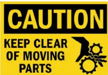
- Keep your hands away from cables and pulleys during operation, other than the designated handles.
- Keep hands, limbs, loose clothing and long hair well out of the way of moving parts.
- Make certain all cables are seated within the pulleys before every use. Frayed or worn cables can be dangerous and may cause injury. Periodically check the cable for any indication of wear.
- Inspect the unit for any sign of wear on parts, hardware becoming loose or cracks on welds. If a problem is found, do not use or allow the machine to be used until the defective part is repaired or replaced.
- It is imperative that you retain this Assembly Instructions and be sure all warning labels are legible and intact. Replacement Assembly Instructions and labels are available from BODYCRAFT. If you are unsure about the proper use of the BODYCRAFT strength machine call your local BODYCRAFT dealer or our Customer Service Department. Contact BODYCRAFT at 800-990-5556 or www.bodycraft.com/customer-support/
IMPORTANT NOTES & RECOMMENDED TOOLS

Important Notes and Tips:
- Before assembly, read all instructions thoroughly and preview diagrams to help make the installation easier.
- Make sure all parts are accounted for and in proper condition before beginning assembly. See the parts list.
- Be cautious not to damage the flooring when assembling. Place a protectant down such as a rubber mat or shipping blanket.
- Let plastics and weight stacks acclimate to room temperature before you begin assembly.
- Two people are required for the safe assembly of this equipment.
- Insert all bolts in the same direction when possible. Do not tighten until instructed.
- Carefully install plastic caps using a rubber mallet.
- When measuring bolt lengths, only measure the shank.
- When the installation is complete, be sure to regularly check for rust or damage, and perform preventative maintenance.

Recommended Tools, Conditions & Items for Assembly:

natural_image
Collection of metal tool holders and a wrench, no visible text or symbolsSOCKET SET 3/8 DRIVE WITH 6" EXT for 7/16, 9/16 & 3/4 SAE

natural_image
Four metallic wrenches arranged vertically (no text or symbols visible)OPEN & CLOSED WRENCHES for 7/16, 9/16 & 3/4 SAE

ALLEN WRENCH SET
1/16" thu 3/8" SAE

natural_image
Close-up of a metallic mechanical tool with a handle and lever (no visible text or symbols)TORQUE WRENCH 3/8 DRIVE

RUBBER Mallet

MINIMUM 65 DEGREES & LOW HUMIDITY

natural_image
Two white rectangular sheets, possibly folded paper or fabric, with no visible text or symbols.CLEAN COTTON CLOTH

MILD CLEANING SOLUTION

100% PURE
SILICONE LUBE

RUBBING ALCOHOL
MACHINE DIMENSIONS
Gym Placement Planner
If possible, please take advantage of the corner fit design.


natural_image
Technical line drawing of a mechanical lifting device with vertical supports and mounting feet (no text or symbols)
FRONT VIEW

SIDE VIEW
OVERALL DIMENSIONS
56.7"W x 40.6"D x 81.9"H
PRODUCT OVERVIEW
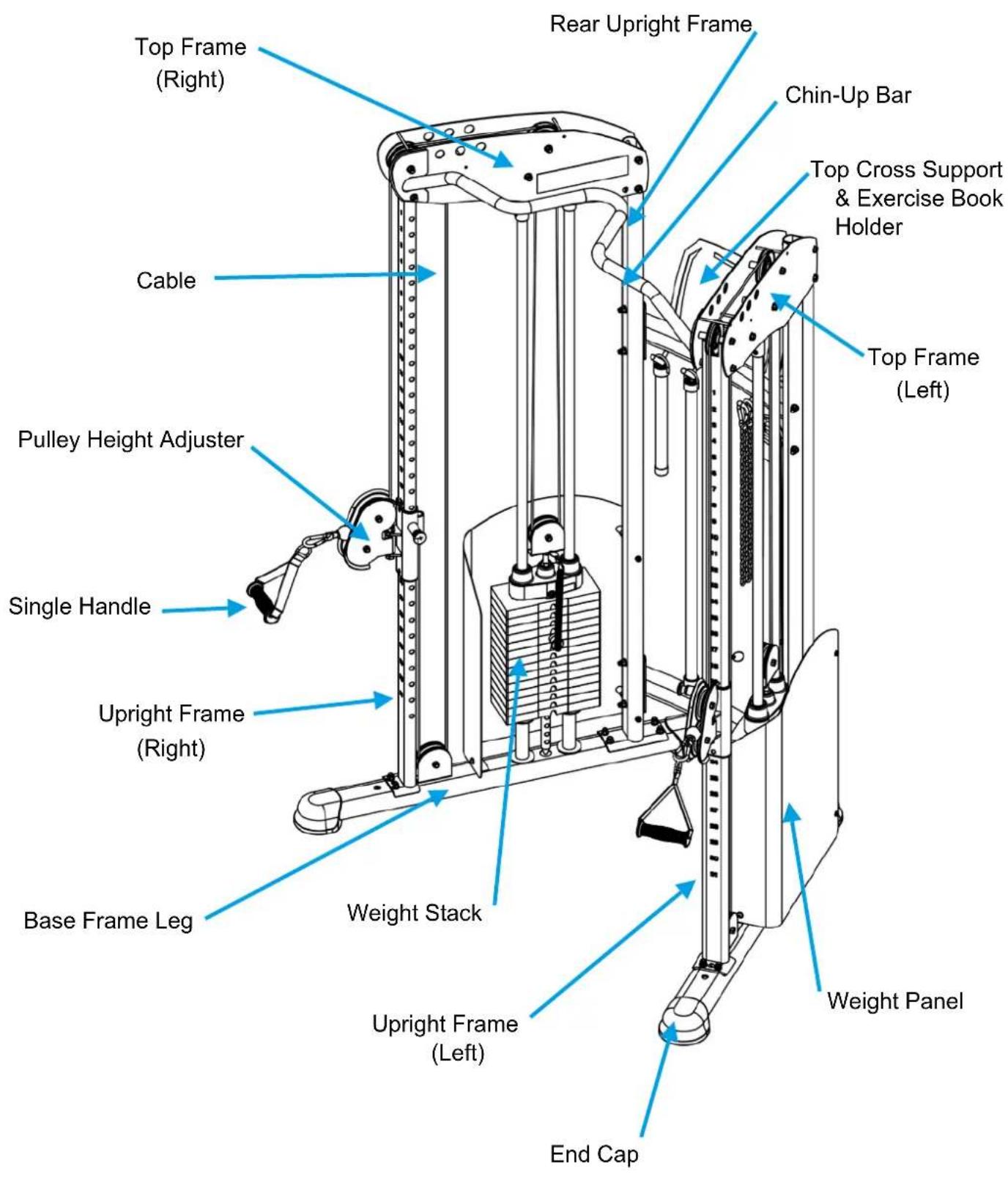
NOTE: Shown with the standard 150 lb stacks.
WEIGHT STACK RATIOS

| Plate Number | Weight at Stack 100% | Weight at Pulley 50% |
| 1 10 5 | ||
| 2 20 10 | ||
| 3 30 15 | ||
| 4 40 20 | ||
| 5 50 25 | ||
| 6 60 30 | ||
| 7 70 35 | ||
| 8 80 40 | ||
| 9 90 45 | ||
| 10 100 50 | ||
| 11 110 55 | ||
| 12 120 60 | ||
| 13 130 65 | ||
| 14 140 70 | ||
| 15 150 75 | ||
| 16 160 80 | ||
| 17 170 85 | ||
| 18 180 90 | ||
| 19 190 95 | ||
| 20 200 100 |
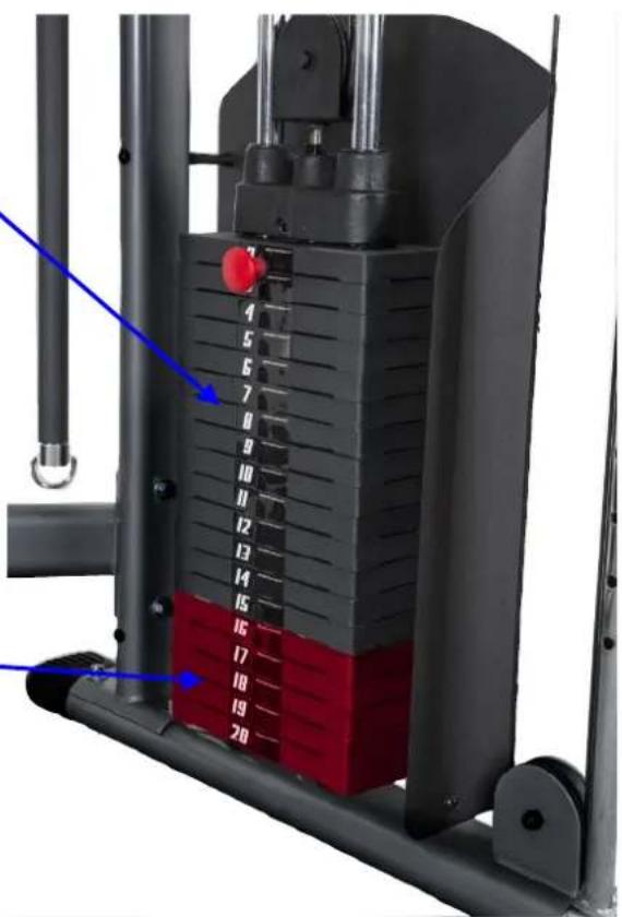
NOTE: Weights are approximate.
Standard Dual 150lb Stack
Upgrade Dual 200lb Stack
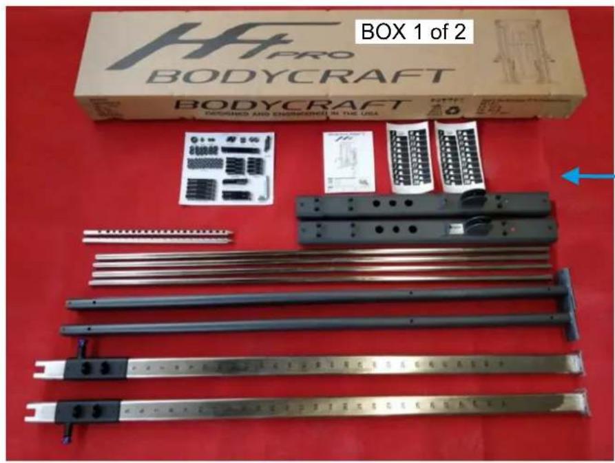
HFT PRO BOXES & WHAT IS INSIDE EACH ONE
Big Box # 1 1 each @ 121 lbs
Big Box # 2 1 each @ 137 lbs
Small Box's 4 each @ 70 lbs per box (Standard Dual 150lb Stack)

natural_image
Product photo of a BodyCRAFT box with metal components and a ruler on a red surface (no visible text or symbols)What's inside each box:
Big Box # 1 1 each @ 121 lbs
Big Box # 2 1 each @ 137 lbs
Small Box's
4 each @ 70 lbs per box (Standard Dual 150lb Stacks)
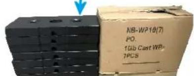
Upgraded to 200lb Stacks? An additional boxes 2 each @ 50 lbs per box


natural_image
Assorted mechanical components laid out on a red surface, including a BodyCRAFT box and various levers and accessories (no text or symbols visible on the objects themselves)BODYCRAFT reserves the right to make improvements at any time which may affect color, parts, materials, size, weight, or any other aspect.
HFT PRO ASSEMBLED PARTS LIST

NOTE: If you are missing a listed part, it likely has been pre-installed in our factory for quality control purposes. Please continue with assembly.
| Part # | Description | QTY |
| 1R | Base Leg Frame - Right | 1 |
| 1L | Base Leg Frame - Left w/ Serial # | 1 |
| 2R | Upright Frame - Right w/ 15R | 1 |
| 3L | Upright Frame - Left w/ 16L | 1 |
| 4 | Rear Upright Frame | 2 |
| 5 | Guide Rod | 4 |
| 6R | Top Frame - Right | 1 |
| 6L | Top Frame - Left | 1 |
| 7 | Chin Bar | 1 |
| 8 | Top Cross Support w/ Exercise Book | 1 |
| 9 | Bottom Cross Support | 1 |
| 10R | Weight Panel-Right | 1 |
| 11L | Weight Panel-Left | 1 |
| 12 | Sport Bar | 1 |
| 13 | Long Bar | 1 |
| 14 | Top Guide Rod Holder w/ Bumper | 2 |
| 17 | Rotating Pulley Holder | 2 |
| 18 | Pulley Block | 2 |
| 19 | Top Plate | 2 |
| 20 | Selector Rod | 4 |
| 21 | 10 lb Weight Plate | 28 |
| 22 | Rubber Donut | 4 |
| 23 | Stack Spacer | 4 |
| 24 | Plastic Guide Rod Holder | 4 |
| 27 | Cable 7,220 mm (284-1/4") | 2 |
| 29 | Ankle Strap | 1 |
| 30 | Chin Assist Strap (47") | 1 |
| 31 | Triceps Rope | 1 |
| 32 | Single Handle | 2 |
| 33 | Chain | 2 |
| 34 | Snap Hook | 4 |
| 36 | Pulley | 16 |
| 38 | End Cap | 4 |
| 41 | Selector Pin w/ Lanyard | 2 |
| 43 | Plastic Studs | 8 |
| 73 | Weight Stack Labels | 2 |
| 74 - 76 | Allen Wrench Set | 1 |
| Hardware Kit | 1 |
73
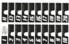

74

75

76
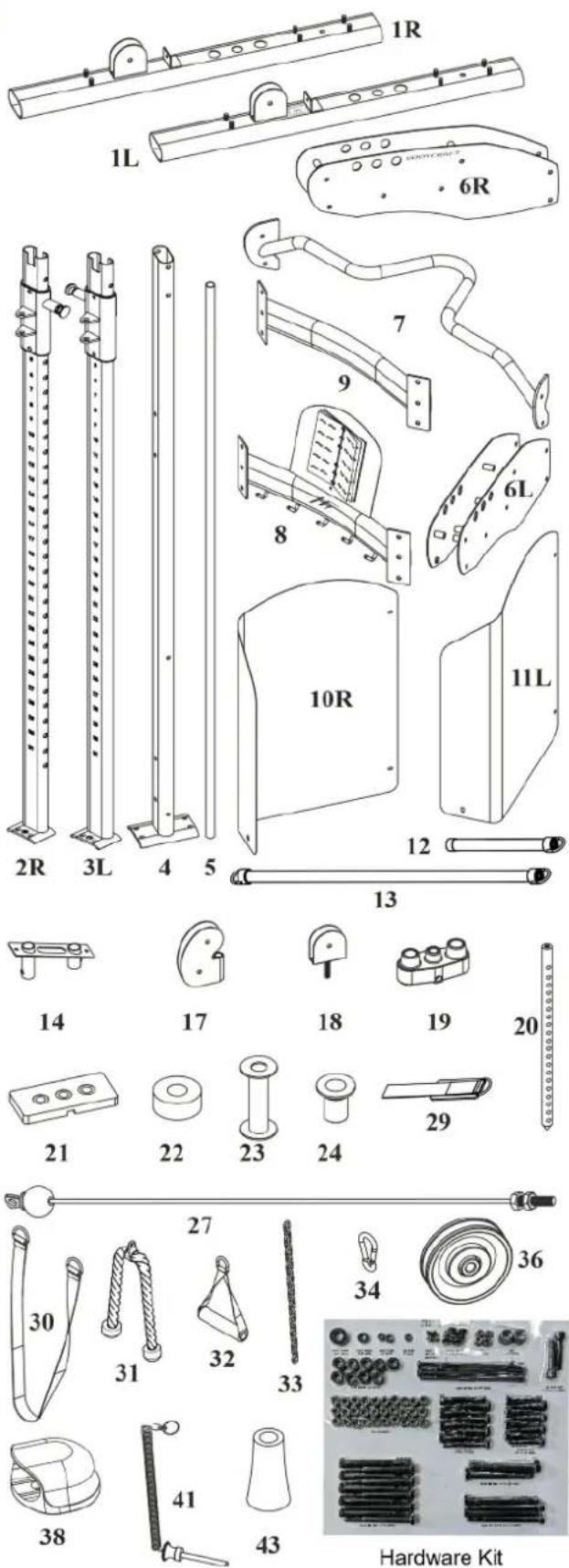
*Part images are not to scale.

NOTE: DO NOT tighten bolts until Step # 7
TWO PEOPLE ARE REQUIRED TO ASSEMBLE THIS STEP.
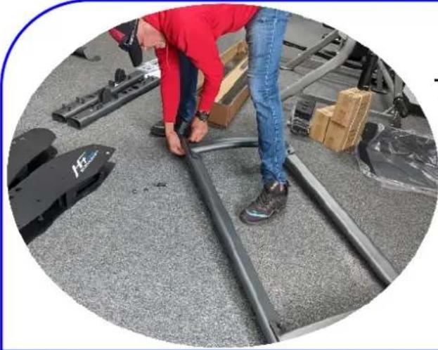
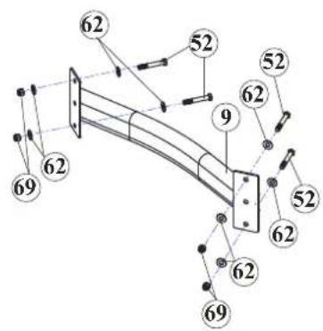
a. Attach Top Cross Support (8) to the Rear Upright Frame (4) using:
- Four 3/8" X 2-1/2" Hex Bolts (52)
- Eight 3/8" Black Washers (62)
- Four 3/8" Black Nylon Nuts (69)
b. Attach Bottom Cross Support (9) to the Rear Upright Frames (4) using:
- Four 3/8" X 2-1/2" Hex Bolts (52)
- Eight 3/8" Black Washers (62)
- Four 3/8" Black Nylon Nuts (69)
natural_image
Person in red jacket and blue jeans working on metal railings with boxes and equipment nearby (no visible text or symbols)TIP: Assembly of Step #1 with both Rear Upright Frames (4) flat down on floor is another way to assemble.


Hardware used for Step #1
| Item # | Description Qty Pic | — | — |
| 52 | 3/8" X 2-1/2" HEX BOLT | 8 | 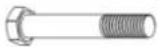 |
| 62 | 3/8" BLACK WASHER | 16 |  |
| 69 | 3/8" BLACK NYLON NUT | 8 |  |
Step # 1 Assembled

natural_image
Technical line drawing of a structural support frame with vertical supports and a curved base (no text or symbols)

NOTE: DO NOT tighten bolts until Step # 7
TIP: Assembly Video of STEP 2


https://youtu.be/jnq
JsKoshfU
a. Install End Caps (38) to the Base Frame Legs
(1) on both (1L) sides.
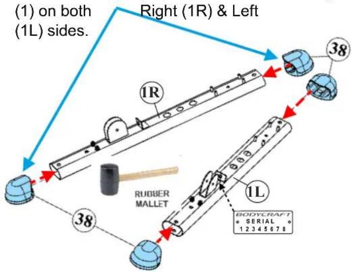
- Eight 3/8" Black Washers (62)
- Eight 3/8" Black Nylon Nuts (69)


Hardware used for Step #2
| Item # | Description Qty Pic | — | — |
| 69 | 3/8" BLACK NYLON NUT | 8 | |
| 62 | 3/8" BLACK WASHER | 8 |


NOTE: DO NOT tighten bolts until Step # 7
a. Attach Right & Left Upright Frame (2R & 3L) to the two Base Frame Legss (1) using:
- Four 3/8" Black Washers (62)
- Four 3/8" Black Nylon Nuts (69)
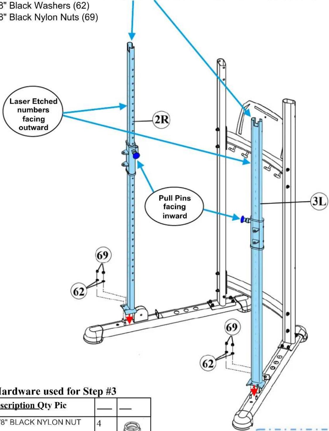
Hardware used for Step #3
| Item # | Description Qty Pic | — | — |
| 69 | 3/8" BLACK NYLON NUT | 4 |  |
| 62 | 3/8" BLACK WASHER | 4 |  |
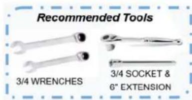
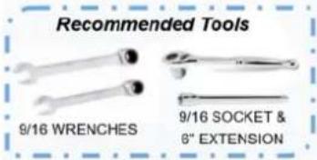
Recommended Tools


NOTE: DO NOT tighten bolts until Step # 7
TWO PEOPLE ARE REQUIRED TO ASSEMBLE THIS STEP.
a. Attach Right Top Frame (6R) to the right rear upright using:
- Two 3/8" X 4" Black Hex Bolts (51)
- Four 3/8" Black Washers (62)
- Two 3/8" Black Nylon Nuts (69)

CAUTION
Pinch Point
Keep hands clear of edges
b. Attach Left Top Frame (6L) to the rear uprights one at a time using:
- Two 3/8" X 4" Black Hex Bolts (51)
- Four 3/8" Black Washers (62)
- Two 3/8" Black Nylon Nuts (69).

Hardware used for Step #4
| Item # | Description Qty Pic | — | — |
| 51 | 3/8" X 4" BLACK HEX BOLTNOTE: 1/4" shorter than (50) | 4 | |
| 62 | 3/8" BLACK WASHER | 8 | |
| 69 | 3/8" BLACK NYLON NUT | 4 |


NOTE: DO NOT tighten bolts until Step # 7
TWO PEOPLE ARE REQUIRED TO ASSEMBLE THIS STEP.
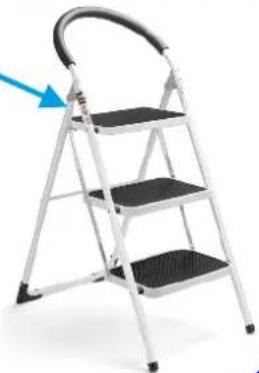
TIP: Using a Step Ladder for the 2 ^nd tech holding the Chin Bar makes the installation easier.
natural_image
Metal ladder with three steps and a curved handle, no text or symbols visible
a. Assemble Chin Bar (7) to the Right Top Frame (6R) using:
- Two 3/8" X 4 1/4" Black Hex Bolts (50)
- Two 3/8" Black Washers (62)
- Two 3/8" Black Nylon Nuts (69)
b. Assemble Chin Bar (7) to the Left Top Frame (6L) using:
- Two 3/8" X 4 1/4" Black Hex Bolts (50)
- Four 3/8" Black Washers (62)
- Two 3/8" Black Nylon Nuts (69)
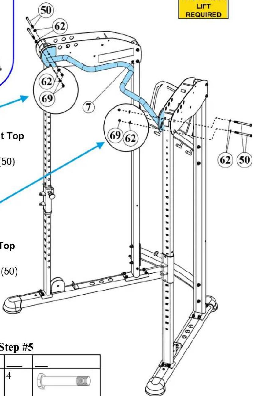
Hardware used for Step #5
| Item # | Description Qty Pic | — | — |
| 50 | 3/8" X 4-1/4" BLACK HEX BOLTNOTE: 1/4” longer than (51) | 4 | 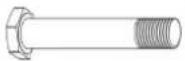 |
| 62 | 3/8" BLACK WASHER | 8 |  |
| 69 | 3/8" BLACK NYLON NUT | 4 |  |

Right Side

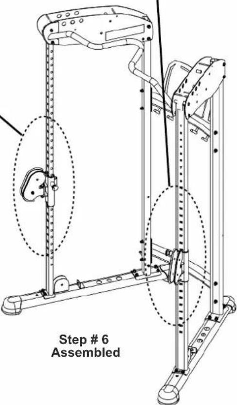
a. Attach two Rotating Pulley Holders (17) to the Right & Left Pulley Height Adjuster (15R & 16L) using:
- Two 1/2" X 3-1/2" Hex Bolts (49)
- Four 1/2" Washers (61)
- Two 1/2" Thin Nylon Nuts (67).
NOTE: Assemble Rotating Pulley Holder upward on both Left and Right Sides.


Left Side

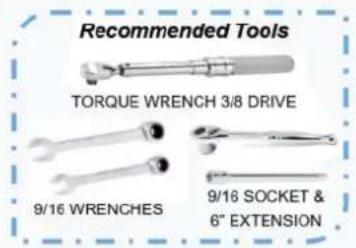
Recommended Tools
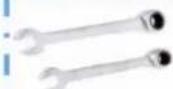
3/4 WRENCHES

3/4 SOCKET &
6° EXTENSION
Hardware used for Step #6
| Item # | Description Qty Pic | — | — |
| 67 | 1/2" THIN NYLON NUT | 2 | |
| 61 | 1/2" WASHER | 4 | |
| 49 | 1/2" X 3-1/2" HEX BOLT | 2 |
Product Assembly
7a: "Torque Time"
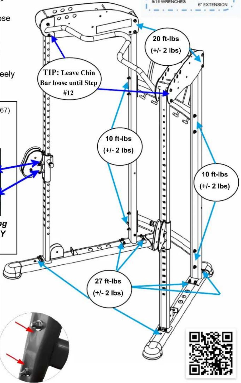
These recommended Torque Specs should be followed for correct assembly and safe operation of this machine.
Tighten to torque specs ensure the bolts and nuts do the following:
- Securely hold the frame and moving parts from coming loose during operation.
- Keep from crushing the frame.
- Avoid stripping the threads on either the bolts or nuts.
- Allow moving parts to adjust freely per the designed intent.
NOTE: Fully tighten Bolt (49) to Nut (67) until the gap between welded tabs and the metal bushing is closed. Then loosen Nut (67) up to 14 turn
until the pulley swivels freely but has almost no play. Loosen or tighten as needed for both Right & Left sides.

Double check if the Rotating Pulley Holder (17) FREELY swivels.
Example of being over-tightened not using the recommended torque specs.
! Tighten Bolts & Nuts at this time to the Recommended Torque Specs
https://www.wikihow.com/Use-a-Torque-Wrench#Video
Product Assembly
8
a. Insert two Plastic Guide Rod Holders (24) into the holes on the Frame Leg (1).
Repeat for both the Right & Left sides.,
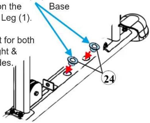
TIP: Leaning Guide Rods (5) inward or outward is acceptable to assemble STEP #8 - STEP #11.
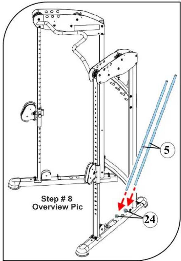

b. Insert the Guide Rods (5) into the Plastic Guide Rod Holders (24).
Repeat for both the Right & Left sides.

c. Lube all four Guide Rods (5), lower half only, with 100% pure Silicone Lube or Teflon PTFE grease. Top half will be done later and potentially keeps lube not getting on installers clothes during the next few assembly steps.
Apply a light layer with a clean rag.
To purchase lube:
www.bodycraft.com/?s=lube&order=asc
Decision Point
150 lb Stacks

200 lb Stacks
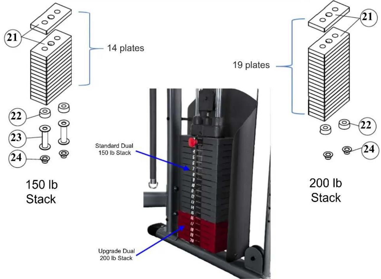
Install STACK SPACERS (23) if you have the 150 lb Stacks, 14 plates per side, total of 28 WEIGHT PLATES (21). Then install rubber donuts (22) on both Right & Left sides.
DO NOT install STACK SPACERS (23) if you have the optional heavy weight 200 lb Stacks, 19 plates per side, total of 38 WEIGHT PLATES (21). Install rubber donuts (22) on both Right & Left sides.
TWO PEOPLE ARE REQUIRED TO ASSEMBLE THIS STEP.


TIP: Leaning Guide Rods (5) inward or outward is acceptable to assemble STEP #8 - STEP #11.
a. With the guides angled slightly, slide Weight Plates (21) one at a time, onto the Guide Rods (5), making sure to orient the selector pin holes facing inward and to the bottom.

natural_image
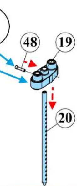
Close-up of a mechanical component with a blue arrow pointing to a feature, no visible text or symbols.b. Attach the Top Plate (19) to the Selector Rod (20) using the Top Plate Bolt (48). Tighten the Top Plate Bolt (48) using a 3/8 Allen Wrench.
{Recommended Torque 30 ft-lb}
c. Perform the same procedure from a and b to opposite side.
Hardware used for Step #10
| Item # | Description Qty Pic | — | — |
| 48 | TOP PLATE BOLT | 2 |
Recommended Tools
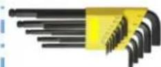
ALLEN WRENCH SET
1/16" thu 3/8" SAE
Product Assembly
a. Slide the Top Plate (19) & Selector Rod (pre assembled in Step #10) onto the Guide Rods (5), running through the center holes of the Weight Plates (21).
TIP: Leaning Guide Rods (5) inward or outward is acceptable to assemble STEP #8 - STEP #11.
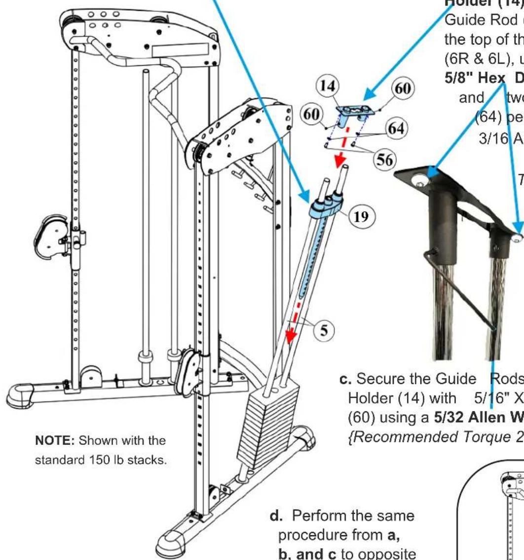
b. Attach Top Guide Rod Holder (14) to the top end of Guide Rod (5) and secure to the top of the Left Top Frames (6R & 6L), using two 5/16" X 5/8" Hex Dome Bolts (56) and two 5/16" Washers (64) per side, using a 3/16 Allen Wrench.
{Recommended Torque 15 ft-lb}
c. Secure the Guide Rods (5) to Guide Rod Holder (14) with 5/16" X 3/8" Set Screws (60) using a 5/32 Allen Wrench. {Recommended Torque 2 ft-lb}
d. Perform the same procedure from a, b, and c to opposite side.
Hardware used for Step #11
| Item # | Description Qty Pic | — | — |
| 56 | 5/16" x 1/2" BOTTOM HEAD BOLT | 4 |  |
| 64 | 5/16" BLACK WASHER | 8 |  |
| 60 | 5/16" x 3/8" SET SCREW | 4 | [THEY] |

NOTE: Actual color of Cables (27) are black. Shown in the assembly steps in RED for easy viewing. Solid RED are cables exposed; dash RED are cables hidden inside the frames or pulleys.

NOTE: DO NOT tighten bolts until Step # 17
Ball End Bolt End
Cable (27)

a. Insert the Bolt End of the Cable (27) through Rotating Pulley Holder (17) as seen in Figure with P1 & P2 below. Then route upward towards P3 on Right Top Frame (6R) for Step #13.
b. Place P1 & P2 Pulleys (36) on top and bottom of Cable (27) securing them with Black Hex Bolts (53) and Black Nylon Nuts (69).

c. Perform the same procedure from a & b to opposite side.

Hardware used for Step #12
| Item # | Description Qty Pic | — | — |
| 53 | 3/8" X 2" BLACK HEX BOLT | 1 | |
| 69 | 3/8" BLACK NYLON NUT | 4 | |
| 62 | 3/8" BLACK WASHER | 8 |

NOTE: Actual color of Cables (27) are black. Shown in the assembly steps in RED for easy viewing.

NOTE: DO NOT tighten bolts until Step # 17
a. Take out Bolt (50) from the front top hole of the Right Top Frame (6R). Then route Cable (27) under the metal bar towards Pulley P4 area and drop cable down towards the weight stack.


c. Pull Cable (27) up in middle of Right Top Frame (6R) and place Pulley P4 (36) under Cable (27). Lower down Cable & Pulley P4 (36). Insert Bolt (51) and secure through frame with Washer (62) and Nut (69).
b. Place Pulley P3 (36) under Cable (27) towards Right Top Frame. Insert Bolt (50) through frame and Pulley P3 securing them with Washer (62) and Nut (69)
Make sure the cable is under the cable retainer
welded-in Metal Bars.
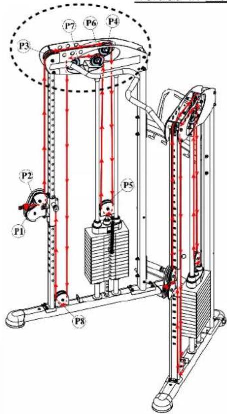

d. Perform the same procedure from a, b, & c to opposite side.

natural_image
Close-up of a mechanical component with a blue arrow pointing to a specific feature (no visible text or symbols)Hardware used for Step #13
| Item # | Description Qty Pic | — | — |
| 50 | 3/8" X 4-1/4" BLACK HEX BOLTNOTE: 1/4" longer than (51) | 2 |  |
| 51 | 3/8" X 4" BLACK HEX BOLTNOTE: 1/4" shorter than (50) | 2 | 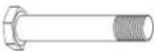 |
| 62 | 3/8" BLACK WASHER | 8 |  |
| 69 | 3/8" BLACK NYLON NUT | 4 |  |

NOTE: DO NOT tighten bolts until Step # 17

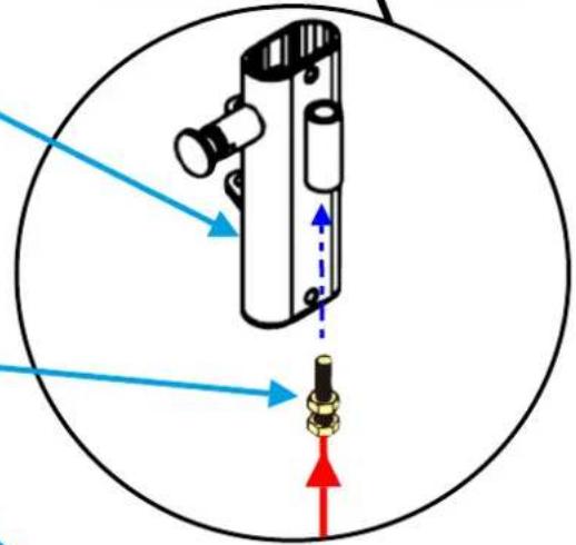
a. Place Selector Pin (41) ring over Pulley Block Bolt and thread on Nut (71) all the way up to the Pulley Block (18) base.
b. Screw down the Pulley Block (18) on the Top Plate (19), min. 1" into the Selector Rod (20). Then go down and around the Pulley Block (18) on the top plate with
c. Place Pulley P5 over Cable (27) towards Pulley Block (18). Secure Pulley P5 with Bolt (53), Washers (62) & Nut (69).
Confirm Cable (27) is back up towards the Top Frame for Pulley 6 coming in Step 15.
d. Perform the same procedure from a, b, and c to opposite side.


Hardware used for Step #14
| Item # | Description Qty Pic | — | — |
| 53 | 3/8" X 2" BLACK HEX BOLT | 2 |  |
| 62 | 3/8" BLACK WASHER | 4 |  |
| 69 | 3/8" BLACK NYLON NUT | 2 |  |
| 71 | 1/2" NUT | 2 |  |
NOTE: DO NOT tighten bolts until Step # 17

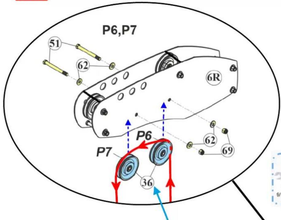
a. Route the cable up and over the two Pulleys P6 & P7 (36) mounted on the Right Top Frame (6R). Then continue down towards the Base Frame Leg (1).
b. Secure Pulleys P6 & P7 (36) with Bolts (51), Washers (62) and Nuts (69).
Make sure the cable is under the cable retainer welded-in Metal Bars.

c. Perform the same procedure from a, b, and c to opposite side.
Hardware used for Step #15
| Item # | Description Qty Pic | — | — |
| 51 | 3/8" X 4" BLACK HEX BOLTNOTE: 1/4" shorter than (50) | 2 |  |
| 62 | 3/8" BLACK WASHER | 4 |  |
| 69 | 3/8" BLACK NYLON NUT | 2 |  |


NOTE: DO NOT tighten bolts until Step # 17
a. Pull Cable (27) down to the Pulley P8 (36) mounted at the Base Frame Leg (1). Enter Cable on weight stack side and pull upward towards bracket at the Right Pulley Height Adjuster (15R). Secure Pulley P8(36) with Bolt (51), Washers (62) and Nut (69).

b. Pull end of Cable (27) bolt end and screw on the bracket at the Right Pulley Height Adjuster (15R). Make sure to screw min. 1/2" of thread into the bracket.
c. Adjust Bolt on Cable (27) end to take out slack in cable. Then hand tighten jam nut.
d. Perform the same procedure from a, b, and c to opposite side.
Hardware used for Step #16
| Item # | Description Qty Pic | — | — |
| 53 | 3/8" X 2" BLACK HEX BOLT | 2 |  |
| 62 | 3/8" BLACK WASHER | 4 |  |
| 69 | 3/8" BLACK NYLON NUT | 2 |  |

natural_image
Close-up of a black cylindrical mechanical component with a blue arrow pointing to a bolt and nut (no text or symbols visible)
Tighten Bolts & Nuts at this time to the Recommended Torque Specs

a. Attach Right & Left Weight Panel (10R & 11L) to the Rear Upright Frames (4) using:

b. Attach Right & Left Weight Panel (10R & 11L) to the Base Frame Leg (1) using:
- Two 5/16" X 1/2" Bottom Head Bolts (55)
- Two 5/16" Washers (65)
c. Tighten all the bolts from Step #18.
- Hex Bolts (54)
{Recommended Torque 5 ft-lb}
- Bottom Head Bolts (55)
{Recommended Torque 17 ft-lb}
Hardware used for Step #18
| Item # | Description Qty Pic | — | — |
| 54 1/4" X | 6" BLACK HEX BOLT | 4 | |
| 66 | 1/4" WASHER | 8 |  |
| 70 | 1/4" NYLON NUT | 4 |  |
| 55 | 5/16" X 1/2" BOTTOM HEAD BOLT | 2 | |
| 64 | 5/16" BLACK WASHER | 2 |  |
Recommended Conditions & Items for Installation of the Weight Stack Stickers

MINIMUM 65 DEGREES & LOW

natural_image
Two white fabric or towel sheets, no text or symbols visibleCLEAN COTTON CLOTH

RUBBING ALCOHOL
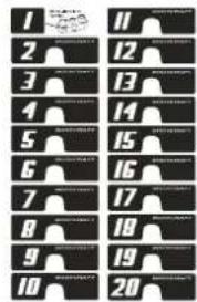
WEIGHT STACK STICKERS-SHEET (74)
IMPORTANT: Before installing the weight stack stickers, it is important to let the weight plates acclimate to room temperature.
a. Clean Top Plate (19) & Weight Plates (21) front surface with Rubbing Alcohol and a Clean Cotton Cloth.
Then wipe dry with another clean cloth or allow to completely air dry.
b. Starting from the Top Plate (19), install Weight Stack Stickers (73) for first sticker #1.


natural_image
Illustration of a hand cleaning a building facade with no text or symbolsc. Continue installing Weight Stack Stickers (74) one at a time starting from the first Weight Plate (21) using sticker #2. Apply all corresponding stickers per each weight plate.

d. Once the label is carefully aligned with each weight plate (21), press each numbered sticker gently onto the correct weight plate. Only rub each sticker and not the surrounding area.
e. Perform the same procedure from a, b, c & d to opposite side.
f. DO NOT "TEST" the sticker by pulling on it at any time after installed on weight stack plates.
NOTE: Allow the adhesive to cure for a minimum of 24 hrs. Room humidity and temperature will affect the cure time.
Final assembly clean up, lube and polish!

a. Remove all assembly stickers
i.e. part numbers
& right / left circles.
Easy to remove with finger nail or plastic scraper.
If adhesive residue is on frame, use rubbing alcohol, then cleaner.

RUBBING ALCOHOL
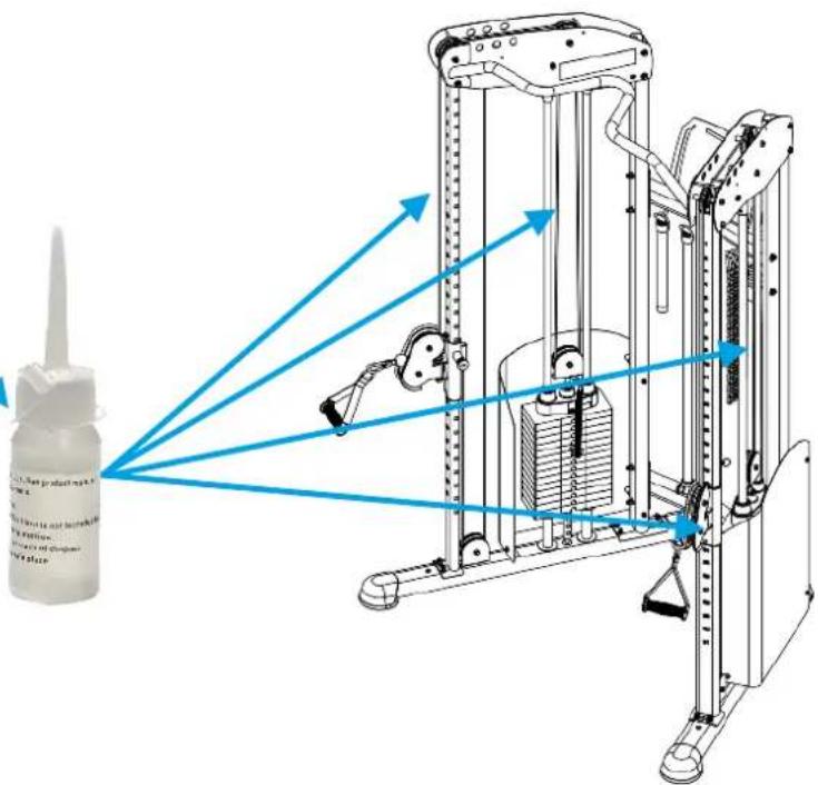
b. Lube all four Guide Rods (5) and the Right & Left Upright Frames (2R & 3L) with 100 % pure Silicone Lube or Teflon PTFE grease.
ONLY apply a light layer with a clean rag.
Then do a set of reps with low weights to spread the lubricant thoroughly the rods. Repeat for both right & left sides.
c. Wipe down frame with mild soap & water, or non-ammonia cleaner
i.e. Simple Green for final cleaning.

natural_image
Two white fabric or towel sheets, overlapping slightly (no text or symbols visible)CLEAN COTTON CLOTH

natural_image
Hand holding a spray bottle with a yellow applicator, no visible text or symbolsMILD CLEANING SOLUTIONS
TIP: For extra protection from finger prints, sweat stains or just plan dirt, apply an automotive grade cleaner wax if desired.
Also makes future cleaning easier.

ASSEMBLY IS COMPLETE
Please take the following steps before using the HFT PRO Functional Trainer:
- Make certain all bolts are tightened securely.
- Make certain all cables are seated into all pulley grooves. A cable rubbing against steel will peel the nylon coating, voiding warranty and resulting in a need for replacement.
- Pre-stretch the cables. Put the Selector Pin (41) in the bottom hole on the weight stack. Pull on the cables with great force, helping remove any kinks and providing any initial cable stretch.
- Be aware the cables can loosen and slightly stretch upon initial use.
- The cables should be adjusted as tight as possible, but not so tight as to lift the Top Plate (19) above the weight stack. Be certain to secure the jam nuts after adjustments are made.
- For better performance, follow the routine maintenance schedule on page 35.
Enjoy many years of a happy & healthy lifestyle.

Double check all bolts, nuts and screws are tightened at this time!
REVIEW ACCESSORIES & OPERATIONS OF ADJUSTMENTS
a. Hang the accessories on the Top Cross Support (8):
- Two Single Handles (32) - One Chin Assist Strap (30)
- One Triceps Rope (31) - One Sport Bar (12)
- One Long Bar (13) - One Ankle Strap (29)
- Two Chains (33) - Four Snap Hooks (34)

natural_image
Metal chain link diagram with blue directional arrows indicating movement (no text or symbols)b. Extension chains (33) add the extra needed length to start any exercise with the given accessories. Just place the Snap Hooks on the desired chain-link location for the exact additional length needed. Then attach another end to the cable pulley end on the machine.

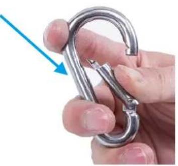
c. Snap Hooks (34) or commonly called Carabiner Clips, are locking (closure) mechanism to allow accessories to be joined to the end of the cable for resistance going directly to the weight stack. Their spring-loaded locking (closure) mechanism helps secure the accessories without it coming off during the exercise. Simply press in the arm, change out the accessories desired and let the spring-loaded arm close.
natural_image
Close-up of a hand holding a metallic chain carabiner with a blue arrow pointing to the hook (no text or symbols visible)d. Pulley Height Adjuster (15R & 16L) can be adjusted up or down the upright frame by pulling outward on the Pop Pin. Then while still holding the Pop Pin outward, slide the Pulley Height Adjuster to desired level and release the spring loaded Pop Pin into the corresponding locking hole.

e. Chin Assist Strap (30) is to assist the user while doing Pull-Ups. The heavier the weight selected, equals less body weight to pull up on the Chin Up Bar.
Secure both Snap Hooks to the chin assist strap end loops onto the right & left cable ends.

natural_image
Person performing a sit-up exercise machine with blue directional arrows indicating movement or force (no text or symbols visible)GENERAL & CABLE INSPECTION
General Inspection and Cleaning
The Frame should be wiped down with a damp cloth and dried on a daily basis. The powder coat finish should be polished with a good car wax on a yearly basis. For Vinyl Upholstery use Lanolin hand cleaner to dissolve sweat and lubricate the vinyl, maintaining its natural flexibility. DO NOT use cleaners such as Lysol or Windex as they will dry out and crack the vinyl. Sweat is corrosive and when left on the frame and components will eventually cause corrosion or rust. When performing these cleaning sessions, it is the perfect time to inspect the equipment and note any problems for the maintenance personnel to correct.
- Check equipment to ensure it is operating properly.
- Check the cables for loose fittings or frayed cable(s) and to ensure seating is proper on the pulleys and cams (if equipped).
- Make sure that the proper weight stack selector pin is with each machine and that the pin functions properly.
- If something appears loose, be sure to have it tightened immediately.
- If a piece of equipment appears damaged or not operating properly, place the piece out-of-service immediately.
Cable Inspection
It is important to inspect the cables frequently, replace any worn out cables to prevent a sudden failure that can result in an injury. Cables are moving parts, meaning cable-wear will occur regardless of the type or size used.
- Inspect cable ends and perform any cable tension adjustments, loosen the jam nut and thread the cable bolt in or out to give cable the proper tension. Re-tightened all jam nuts when adjustment is complete and make sure the cable bolt is threaded 1/3 into the socket of the selector stem in the top plate.
- Check the cables as they pass over all pulley wheels. Visually inspect the cables and pulleys. A cable that is wearing will exhibit a ballooned surface that passes over the pulleys. This is an early warning sign to replace the cable(s).
Bearing and linear bearing systems have advanced over the years, but they must be maintained on a regular basis if you expect them to last and perform efficiently. BODY-CRAFT uses only the highest quality bearings and linear motion components that are virtually trouble-free but they require the regular preventive maintenance to ensure long-lasting performance.
- Bronze bushings: Recommend on a yearly basis to spray a Teflon-base lubricant (silicone-free) directly onto the shaft as it passes through these bushings. Spray a small amount onto the shaft and rotate it through its complete movement and wipe off any excess.
- Weight stack guide rods: Use Silicone Spray lubricant and this time spray onto a rag and wipe the guide rods down with this rag on a weekly basis. DO NOT use WD-40 or other lubricants as they attract dirt and will create a mess between the weight plates and bushings.
- Sealed bearings pivot points: As the name implies, they are protected from the outside environment and require no lubrication. During the machine wipe down, wipe the external bearing surfaces with the damp rag and dry to prevent the build up of dust and sweat.
- Linear bearing systems (if equipped): These are precision, high load components that require regular maintenance. Dirt and corrosion are the major culprits in linear bearing failure. The hardened shafts must be wiped down monthly and lubricated with a light layer of Teflon grease. We recommend a Teflon-based (silicone-free) gel/grease for this purpose. Lack of care and maintenance will result in corrosion of the linear shaft causing the bearings to become clogged and jammed.
If you perform the maintenance procedures, you will increase the life of the machine and ultimately lower your maintenance costs with fewer replaced components and downtime.

BODYCRAFT 7699 GREEN MEADOWS DR. LEWIS CENTER, OHIO 43035

800.990.5556 SERVICE@BODYCRAFT.COM WWW.BODYCRAFT.COM
STRENGTH CABLE WEAR INDICATORS

Casing can crack or fracture under strains during use. Any crack in the casing merits cable replacement even if no wire rope is exposed. This cable needs to be replaced as soon as possible.

Inspect casing to ensure wire rope is not tearing, twisting, or binding within and coil causing bulge to appear. Cable should retain same outside diameter throughout.
This cable needs to be replaced as soon as possible.

Any exposed wire rope protruding through the casing or at either end, has lost its structural integrity. Section of cable is compressed and will not retain its shape (outside diameter).
STOP USING THE MACHINE: This cable needs to be replaced immediately.

Cable has a kink and prohibits cable from lying straight. Wire rope may be unraveling beneath the casing, causing a compromise of its structural integrity.
STOP USING THE MACHINE: This cable needs to be replaced immediately.

Watch for component end of cable to pull away from cable assembly and look for exposed wire rope.
STOP USING THE MACHINE: This cable needs to be replaced immediately.
STRENGTH MAINTENANCE & ROUTINE SCHEDULE
| ROUTINE SCHEDULE | LIGHT COMMERCIAL | HOME |
| Clean: Upholstery. | DAILY | 1 - 2 WEEKS |
| Inspect: Cables or Belts and their tension. | DAILY | 1 - 2 WEEKS |
| Inspect: Links, Pull Pins, Snap Locks, Swivels, and Weight Stack Pins. | DAILY | 1 - 2 WEEKS |
| Inspect: Accessory Bars and Handles. | WEEKLY | 3 - 6 MONTHS |
| Inspect: All Label and Weight Stack Stickers. | WEEKLY | 3 - 6 MONTHS |
| Inspect: All Nuts and Bolts, tighten if needed. | WEEKLY | 3 - 6 MONTHS |
| Inspect: Anti-Skid Surface. | WEEKLY | 3 - 6 MONTHS |
| Clean & Lubricate: Guide Rods with 100% Silicone or a Teflon based lubricant with Super Lube (a PTFE grease). | MONTHLY | 3 - 6 MONTHS |
| Lubricate: Seat Sleeves, Bushings, Linear Bearing. | MONTHLY | 3 - 6 MONTHS |
| Clean and Wax: All Glossy Finishes. | 6 MONTHS | YEARLY |
| Repack with Grease: Linear Bearings. | 6 MONTHS | YEARLY |
| Replace: Cables, Belts and Connecting Parts when showing signs of wear. | YEARLY | 2 - 4 YEARS |
Exploded View - Detailed w/ Left Side (L)

NOTE: #23 only used with 150lb stacks.
View Keys
Red dotted (large): Structural parts assembled direction.
Red dotted (med): Sub-parts assembled direction.
Blue dotted lines (small): Hardware assembled direction.
HFT PRO V1.4
Exploded View - Detailed w/ Right Side (R)

View Keys
Red dotted (large): Structural parts assembled direction.
Red dotted (med): Sub-parts assembled direction.
Blue dotted lines (small): Hardware assembled direction.
HFT PRO V1.4
Exploded View - Detailed w/ Center (C) & Accessories (A)


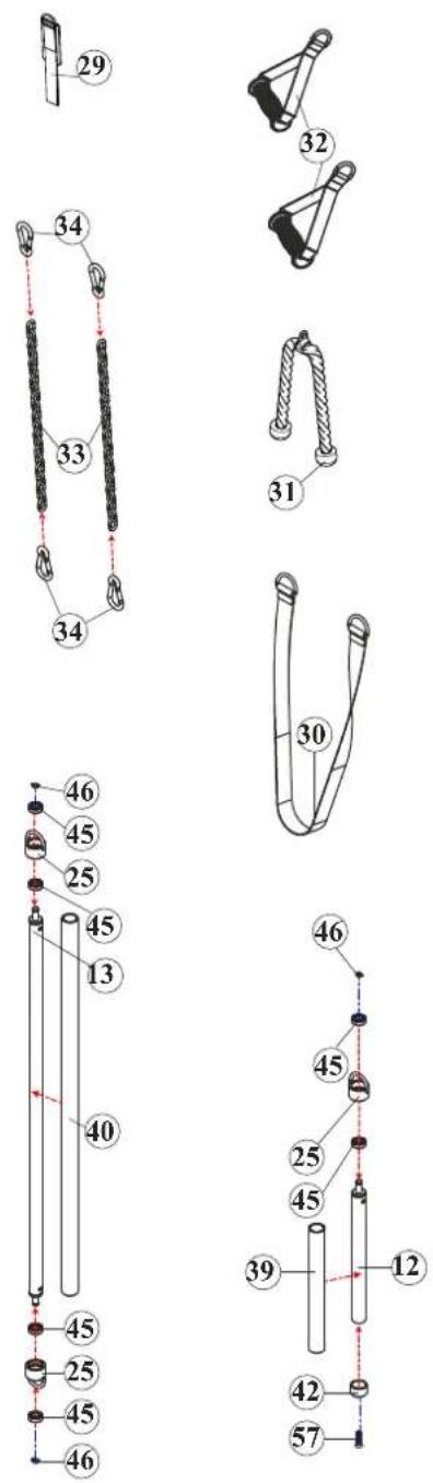

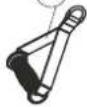


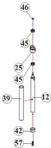
View Keys
Red dotted (large): Structural parts assembled direction.
Red dotted (med): Sub-parts assembled direction.
Blue dotted lines (small): Hardware assembled direction.
HFT PRO V1.4
Exploded View - Detailed Part Numbers
| Part # | Description QTY | |
| 1R | Base Leg Frame - Right 1 | |
| 1L | Base Leg Frame - Left w/ Serial # 1 | |
| 2R | Upright Frame - Right 1 | |
| 3L | Upright Frame - Left 1 | |
| 4 | Rear Upright Frame 2 | |
| 5 | Guide Rod 4 | |
| 6R | Top Frame - Right 1 | |
| 6L | Top Frame - Left 1 | |
| 7 | Chin Bar 1 | |
| 8 | Top Cross Support 1 | |
| 9 | Bottom Cross Support | 1 |
| 10R | Weight Panel-Right | 1 |
| 11L | Weight Panel-Left | 1 |
| 12 | Sport Bar 1 | |
| 13 | Long Bar | 1 |
| 14 | Top Guide Rod Holder | 2 |
| 15R | Pulley Height Adjuster - Right | 1 |
| 16L | Pulley Height Adjuster - Left | 1 |
| 17 | Rotating Pulley Holder 2 | |
| 18 | Pulley Block | 2 |
| 19 | Top Plate | 2 |
| 20 | Selector Rod | 4 |
| 21 | 10 lb Weight Plate | 28 |
| 22 | Rubber Donut | 4 |
| 23 | Stack Spacer | 4 |
| 24 | Plastic Guide Rod Holder | 4 |
| 25 | Sport Bar Collar (Pre-assembled) | 3 |
| 26 | Exercise Book Holder (Preassembled) | 1 |
| 27 | Cable 7,220 mm (284-1/4") | 2 |
| 28 | Exercise Book (Preassembled) | 1 |
| 29 | Ankle Strap | 1 |
| 30 | Chin Assist Strap (47") | 1 |
| 31 | Triceps Rope | 1 |
| 32 | Single Handle | 2 |
| 33 | Chain | 2 |
| 34 | Snap Hook | 4 |
| 35 | Pop-Pin (Preinstalled) 2 |
| Part # | Description | QTY | |
| 36 | Pulley | 16 | |
| 37 | Plastic Bushing (Preinstalled) | 4 | |
| 38 | End Cap | 4 | |
| 39 | 1" x 295L Foam Grip (Preassembled) | 1 | |
| 40 | 1" x 900L Foam Grip (Preassembled) | 1 | |
| 41 | Selector Pin w/Lanyard | 2 | |
| 42 | Spacer (Preassembled) | 1 | |
| 43 | Plastic Studs (1 pc Preassembled) | 9 | |
| 44 | 1/2" Bushing | 4 | |
| 45 | Bearing (Preassembled) | 6 | |
| 46 | C-Ring | 3 | |
| 47 | Rubber Cover | 5 | |
| 48 | Top Plate Bolt | 2 | |
| 49 | 1/2" x 3-1/2" Black Hex Bolt | 2 | |
| 50 | 3/8" x 4-1/4" Black Hex Bolt | 4 | |
| 51 | 3/8" x 4" Black Hex Bolt | 10 | |
| 52 | 3/8" x 2-1/2" Black Hex Bolt | 8 | |
| 53 | 3/8" x 2" Black Hex Bolt | 8 | |
| 54 | 1/4" x 6" Black Hex Bolt | 4 | |
| 55 | 5/16" x 1/2" Black Bottom Head Bolt 2 | ||
| 56 | 5/16" x 5/8" Black Bottom Head Bolt 4 | ||
| 57 | 5/16" x 1-1/4" Black Sunken Head Bolt | 1 | |
| 58 | M4 x 40L Black Sunken Head Screw | 1 | |
| 59 | M4 x 10L Black Sunken Head Screw | 1 | |
| 60 | 5/16" x 3/8" Set Screw 4 | ||
| 61 | 1/2" Black Washer | 4 | |
| 62 | 3/8" Black Washer | 72 | |
| 63 | M4 x 10L Phillips Head Screw (Preinstalled) | 4 | |
| 64 | 5/16" Black Washer | 6 | |
| 65 | φ4 Black Big Washer (Preinstalled) | 4 | |
| 66 | 1/4" Black Washer | 8 | |
| 67 | 1/2" Black Thin Nylon Nut (Low Ht) | 2 | |
| 68 | Bumper (Preinstalled) | 2 | |
| 69 | 3/8" Black Nylon Nut | 42 | |
| 70 | 1/4" Black Nylon Nut 4 | ||
| 71 | 1/2" Nut (Preinstalled) | 2 | |
| 72 | M4 Black Nylon Nut (Preinstalled) | 2 | |
| 73 | Weight Stack Labels 2 | ||
| 74 | Allen Wrench 5/32 | 1 | |
| 75 | Allen Wrench 3/16 | 1 | |
| 76 | Allen Wrench 3/8 1 | ||
HFT PRO V1.4
Detailed Parts List w/ Images 1 OF 2

NOTE: If you are missing a listed part, it likely has been pre-installed in our factory for quality control purposes. Please continue with assembly.
| Part # | Description | QTY |
| 1R | Base Leg Frame - Right | 1 |
| 1L | Base Leg Frame - Left w/ Serial # | 1 |
| 2R | Upright Frame - Right | 1 |
| 3L | Upright Frame - Left | 1 |
| 4 | Rear Upright Frame | 2 |
| 5 | Guide Rod | 4 |
| 6R | Top Frame - Right | 1 |
| 6L | Top Frame - Left | 1 |
| 7 | Chin Bar | 1 |
| 8 | Top Cross Support | 1 |
| 9 | Bottom Cross Support | 1 |
| 10R | Weight Panel-Right | 1 |
| 11L | Weight Panel-Left | 1 |
| 12 | Sport Bar | 1 |
| 13 | Long Bar | 1 |
| 14 | Top Guide Rod Holder | 2 |
| 15R | Pulley Height Adjuster - Right | 1 |
| 16L | Pulley Height Adjuster - Left | 1 |
| 17 | Rotating Pulley Holder | 2 |
| 18 | Pulley Block | 2 |
| 19 | Top Plate | 2 |
| 20 | Selector Rod | 4 |
| 21 | 10 lb Weight Plate | 28 |
| 22 | Rubber Donut | 4 |
| 23 | Stack Spacer | 4 |
| 24 | Plastic Guide Rod Holder | 4 |
| 25 | Sport Bar Collar (Pre-assembled) | 3 |
| 26 | Exercise Book Holder (Preassembled) | 1 |
| 27 | Cable 7,220 mm (284-1/4") | 2 |
| 28 | Exercise Book (Preassembled) | 1 |
| 29 | Ankle Strap | 1 |
| 30 | Chin Assist Strap (47") | 1 |
| 31 | Triceps Rope | 1 |
| 32 | Single Handle | 2 |
| 33 | Chain | 2 |
| 34 | Snap Hook | 4 |
| 35 | Pop-Pin (Preinstalled) | 2 |
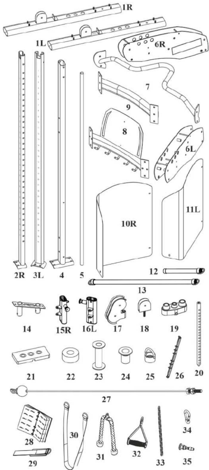
*Part images are not to scale.
Detailed Parts List w/ Images 2 of 2
| Part # | Description | QTY |
| 36 | Pulley | 16 |
| 37 | Plastic Bushing (Preinstalled) | 4 |
| 38 | End Cap | 4 |
| 39 | 1" x 295L Foam Grip (Preassembled) | 1 |
| 40 | 1" x 900L Foam Grip (Preassembled) | 1 |
| 41 | Selector Pin w/Lanyard | 2 |
| 42 | Spacer (Preassembled) | 1 |
| 43 | Plastic Studs (1 pc Preassembled) | 9 |
| 44 | 1/2" Bushing | 4 |
| 45 | Bearing (Preassembled) | 6 |
| 46 | C-Ring | 3 |
| 47 | Rubber Cover | 5 |
| 48 | Top Plate Bolt | 2 |
| 49 | 1/2" x 3-1/2" Black Hex Bolt | 2 |
| 50 | 3/8" x 4-1/4" Black Hex Bolt | 4 |
| 51 | 3/8" x 4" Black Hex Bolt | 10 |
| 52 | 3/8" x 2-1/2" Black Hex Bolt | 8 |
| 53 | 3/8" x 2" Black Hex Bolt | 8 |
| 54 | 1/4" x 6" Black Hex Bolt | 4 |
| 55 | 5/16" x 1/2" Black Bottom Head Bolt | 2 |
| 56 | 5/16" x 5/8" Black Bottom Head Bolt | 4 |
| 57 | 5/16" x 1-1/4" Black Sunken Head Bolt | 1 |
| 58 | M4 x 40L Black Sunken Head Screw | 1 |
| 59 | M4 x 10L Black Sunken Head Screw | 1 |
| 60 | 5/16" x 3/8" Set Screw | 4 |
| 61 | 1/2" Black Washer | 4 |
| 62 | 3/8" Black Washer | 72 |
| 63 | M4 x 10L Phillips Head Screw (Preinstalled) | 4 |
| 64 | 5/16" Black Washer | 6 |
| 65 | φ4 Black Big Washer (Preinstalled) | 4 |
| 66 | 1/4" Black Washer | 8 |
| 67 | 1/2" Black Thin Nylon Nut (Low Ht) | 2 |
| 68 | Bumper (Preinstalled) | 2 |
| 69 | 3/8" Black Nylon Nut | 42 |
| 70 | 1/4" Black Nylon Nut | 4 |
| 71 | 1/2" Nut (Preinstalled) | 2 |
| 72 | M4 Black Nylon Nut (Preinstalled) | 2 |
| 73 | Weight Stack Labels | 2 |
| 74 | Allen Wrench 5/32 | 1 |
| 75 | Allen Wrench 3/16 | 1 |
| 76 | Allen Wrench 3/8 | 1 |
*Part images are not to scale.


PRODUCT WARRANTY
VALID FOR USA AND CANADA ONLY
(Please consult with your local distributor for warranty info specific to your region).
BODYCRAFT warrants its products to be free of defects in materials and workmanship for the time stated below to the original purchaser.
Register your product within 30 days of purchase at www.bodycraft.com or call 800-990-5556
This warranty is valid only in accordance with the following conditions:
The warranty begins on the original purchase date at retail and ends when the original owner disposes of it, either through sale, gift, or otherwise. This warranty is not transferable and is only valid to the original purchaser.
This warranty is available only for purchases made within and the original purchaser currently residing in the USA and Canada. Please consult with your local distributor for warranty information specific to your region. The product must have been registered within 30 days of the original purchase date or supply proof of purchase to validate warranty (original sales invoice).
This warranty does not extend to any losses or damages due to accident, misuse, abuse, neglect, negligence, unauthorized modification or alteration, use beyond rated capacity, unsuitable power sources or environmental conditions, water, tampering, cosmetic damages, or improper installation, handling, repair, maintenance, or application, or lack of proper maintenance.
If the item exhibits such a defect, BODYCRAFT will, at its option, repair or replace it without cost for parts. Shipping and handling charges may apply. (BODYCRAFT may require return of the part(s) or photographic evidence of the damaged part(s) prior to replacement.) Serial number is required. Parts repaired or replaced will be warranted for the remainder of the original warranty period only.
Residential Warranty for Strength Equipment:
Frame: Lifetime, Parts: Lifetime
Commercial Warranty for Strength Equipment:
Frame: 10 years, Parts: 2 years
This warranty excludes the following:
- The warranty does not cover normal maintenance or labor charges unless labor terms are listed above.
- Normal cosmetic wear on parts such as paint, seat coverings, foot rails, labels and logos.
- Any accessories not included in the original packaging.
- Warranty does not cover normal wear and tear.
* This warranty is in lieu of all warranties, expressed or implied, and/or all other obligations or liabilities on our part, and we neither assume nor authorize any person to assume for us any other obligation or liability in connection with the sale of your BODYCRAFT product. Under no circumstances shall we be liable by virtue of this warranty or otherwise for damage to any person or property whatsoever for any special, indirect, incidental, secondary or consequential damage of any nature whatsoever arising out of the use or inability to use the BODYCRAFT product.
Register your product's warranty at www.bodycraft.com/product-registration/
PRODUCT WARRANTY REGISTRATION
Thank you for purchasing a BODYCRAFT product. To validate the product warranty the fast and easy way, please go on-line now to https://www.bodycraft.com/product-registration.html and register your product. The information you provide will never be distributed to any other individuals or agencies for any purpose. If you prefer to mail your warranty card, have the owner of the product complete the information below and return it to BODYCRAFT within 30 days from the date of equipment installation.
Please Note: Failure to register this product will result in no servicing or authorization of parts to be shipped.
To mail your warranty information, please fill in the information below and mail to: Service Dept., BODYCRAFT, 7699 Green Meadows Dr., Lewis Center, Ohio 43035 (or save postage and register online at https://www.bodycraft.com/product-registration.html)
WARRANTY REGISTRATION
PLEASE PROVIDE BOTH SERIAL NUMBERS BELOW. REQUIRED FOR WARRANTY REGISTRATION:
BASE UNIT SERIAL NUMBER:
OPTIONS SERIAL NUMBER:
Model Type: ____
Date of Purchase ____
Your Company Name ____
Contact First Name
Contact Last Name
Address
City State ZIP
Email Address____Website____
Phone____Fax____
- Where did you first learn about BODYCRAFT?
a. Dealer b. Website
c. Advertisement d. Referral
e. Current Customer f. Other
- Why did you purchase a BODYCRAFT product?
a. Design/Appearance b. Dealer Suggestion
c. Price/Value d. Quality Construction
e. Performance f. BODYCRAFT Reputation
__ g. Other: ____
- Please indicate your type of facility:
a. Apartment/Condo b. Corporate Fitness Center
c. Municipality d. Health Club/Gym/Spa
e. Hotel/Resort f. Military Base
____ g. Student Rec Center ____ h. Home
- What other types of equipment does your company or home currently own?
a. Treadmill Brand
b. Elliptical Brand
c. Bike/Indoor Cycle Brand
d. Free Weights/Gym Brand
- How many people use your facility on a daily basis?
a. <25 b. 25-75
_ c. 76-150 _ d. 150+
- Do you plan to purchase more fitness equipment in the next 6-12 months?
____Yes ____No
- If you answered "yes" to question 6, what type do you plan to purchase?
a. Treadmill b. Elliptical
c. Bike/Indoor Cycle ____ d. Free Weights
e. Gym f. Other
- Would you recommend BODYCRAFT to other club or home owners?
____Yes ____No
- You are a valued BODYCRAFT customer and your suggestions allow us to continually improve your experience. Is there anything else you would like us to know? Please explain:

natural_image
Simple black-and-white icon of a telephone handset inside a circle (no text or symbols)800.990.5556
SERVICE@BODYCRAFT.COM
WWW.BODYCRAFT.COM

BODYCRAFT
7699 GREEN MEADOWS DR.
LEWIS CENTER, OHIO 43035
- Owner's Manual
- Congratulations and Welcome to the BODYCRAFT Family
- TABLE OF CONTENTS
- Product Safety & Important Notes
- Product Overview
- How to Assemble the HFT PRO
- Maintenance & Repairs
- Warranty
- PRODUCT SAFETY
- IMPORTANT NOTES & RECOMMENDED TOOLS
- Important Notes and Tips:
- Recommended Tools, Conditions & Items for Assembly:
- MACHINE DIMENSIONS
- Gym Placement Planner
- HFT PRO BOXES & WHAT IS INSIDE EACH ONE
- Small Box's
- HFT PRO ASSEMBLED PARTS LIST
- NOTE: DO NOT tighten bolts until Step # 7
- TWO PEOPLE ARE REQUIRED TO ASSEMBLE THIS STEP.
- CAUTION
- Product Assembly
- 7a: "Torque Time"
- ! Tighten Bolts & Nuts at this time to the Recommended Torque Specs
- Decision Point
- NOTE: DO NOT tighten bolts until Step # 17
- Recommended Conditions & Items for Installation of the Weight Stack Stickers
- Final assembly clean up, lube and polish!
- ASSEMBLY IS COMPLETE
- Please take the following steps before using the HFT PRO Functional Trainer:
- REVIEW ACCESSORIES & OPERATIONS OF ADJUSTMENTS
- GENERAL & CABLE INSPECTION
- General Inspection and Cleaning
- Cable Inspection
- STRENGTH CABLE WEAR INDICATORS
- Exploded View - Detailed w/ Left Side (L)
- Exploded View - Detailed w/ Right Side (R)
- Exploded View - Detailed w/ Center (C) & Accessories (A)
- Detailed Parts List w/ Images 1 OF 2
- Detailed Parts List w/ Images 2 of 2
- PRODUCT WARRANTY
- VALID FOR USA AND CANADA ONLY
- This warranty is valid only in accordance with the following conditions:
- This warranty excludes the following:
- PRODUCT WARRANTY REGISTRATION
- WARRANTY REGISTRATION
Brand : BodyCraft
Model : HFT Pro
Category : Fitness Equipment