TS 19 - Wi-Fi repeater FLUKE - Free user manual and instructions
Find the device manual for free TS 19 FLUKE in PDF.


| Product Type | Portable Test Telephone (Butt-in Set) |
| Model | TS19 |
| Brand | Fluke Networks |
| Dimensions (L x W x H) | 8.75 in x 2.375 in x 3.375 in (22.2 cm x 6.03 cm x 8.57 cm) |
| Weight | 10.8 oz (0.307 kg) maximum |
| Power Source | Line-powered from telephone line (no internal battery) |
| Loop Limit | 2.4 kΩ maximum at 48 VDC (15 mA minimum loop current) |
| DC Resistance (Talk Mode) | 150 Ω typical at 80 mA |
| AC Impedance (Monitor Mode) | Low: 600 Ω at 1 kHz (Ring position); High: >100 kΩ at 1 kHz (HI Z position) |
| Dialing Modes | DTMF (Tone) and Dial Pulse (Rotary) selectable via PULSE/TONE switch |
| Rotary Dial Output | Pulsing rate 10 pps ±0.5 pps, 60% ±2% break, 800 ms interdigit interval |
| DTMF Output | Frequency error ±1% max, level per tone pair +2 dBm to -8 dBm |
| Last Number Redial | Up to 18 digits, memory holds 15 minutes after disconnection |
| Ringer | Electronic piezo-electric, on/off via HI Z/RING/TALK switch |
| Monitoring Modes | High impedance (HI Z) for non-disruptive monitoring; low impedance (RING) with ringer |
| Polarity Check | Red LED indicates tip positive when red lead on tip and black on ring |
| Line Cords (field replaceable) | Piercing pin cord, banana jack cord, ground start cord, angled bed-of-nails cord |
| Belt Clip | Spring-loaded, field replaceable (order P3218249) |
| Environmental Operating Temp | -5°C to +40°C (23°F to 104°F) |
| Environmental Storage Temp | -40°C to +66°C (-40°F to 151°F) |
| Drop Test | 1 meter, 4 times |
| Maximum Altitude | 3,000 m (10,000 ft) |
| Safety Certifications | CE, CSA C22.2 No. 60950-1, UL/ANSI 3111-1 |
| EMC Compliance | FCC Part 15, ICES-003, AS/NZS 3548, EN 55022, EN 61326 |
| Warranty (mainframe) | 18 months from purchase date |
Frequently Asked Questions - TS 19 FLUKE
User questions about TS 19 FLUKE
0 question about this device. Answer the ones you know or ask your own.
Ask a new question about this device
Download the instructions for your Wi-Fi repeater in PDF format for free! Find your manual TS 19 - FLUKE and take your electronic device back in hand. On this page are published all the documents necessary for the use of your device. TS 19 by FLUKE.
USER MANUAL TS 19 FLUKE
Portable Test Telephone
Users Guide
LIMITED WARRANTY AND LIMITATION OF LIABILITY
Each Fluke Networks product is warranted to be free from defects in material and workmanship under normal use and service. The warranty period for the mainframe is 18 months and begins on the date of purchase. Parts, accessories, product repairs and services are warranted for 90 days, unless otherwise stated. Ni-Cad, Ni-MH and Li-Ion batteries, cables or other peripherals are all considered parts or accessories. The warranty extends only to the original buyer or end user customer of a Fluke Networks authorized reseller, and does not apply to any product which, in Fluke Networks' opinion, has been misused, abused, altered, neglected, contaminated, or damaged by accident or abnormal conditions of operation or handling. Fluke Networks warrants that software will operate substantially in accordance with its functional specifications for 90 days and that it has been properly recorded on non-defective media. Fluke Networks does not warrant that software will be error free or operate without interruption.
Fluke Networks authorized resellers shall extend this warranty on new and unused products to end-user customers only but have no authority to extend a greater or different warranty on behalf of Fluke Networks. Warranty support is available only if product is purchased through a Fluke Networks authorized sales outlet or Buyer has paid the applicable international price. Fluke Networks reserves the right to invoice Buyer for importation costs of repair/replacement parts when product purchased in one country is submitted for repair in another country.
Fluke Networks warranty obligation is limited, at Fluke Networks option, to refund of the purchase price, free of charge repair, or replacement of a defective product which is returned to a Fluke Networks authorized service center within the warranty period.
To obtain warranty service, contact your nearest Fluke Networks authorized service center to obtain return authorization information, then send the product to that service center, with a description of the difficulty, postage and insurance prepaid (FOB destination). Fluke Networks assumes no risk for damage in transit. Following warranty repair, the product will be returned to Buyer, transportation prepaid (FOB destination). If Fluke Networks determines that failure was caused by neglect, misuse, contamination, alteration, accident or abnormal condition of operation or handling, or normal wear and tear of mechanical components, Fluke Networks will provide an estimate of repair costs and obtain authorization before commencing the work. Following repair, the product will be returned to the Buyer transportation prepaid and the Buyer will be billed for the repair and return transportation charges (FOB Shipping point).
THIS WARRANTY IS BUYER'S SOLE AND EXCLUSIVE REMEDY AND IS IN LIEU OF ALL OTHER WARRANTIES, EXPRESS OR IMPLIED, INCLUDING BUT NOT LIMITED TO ANY IMPLIED WARRANTY OR MERCHANTABILITY OR FITNESS FOR A PARTICULAR PURPOSE. FLUKE NETWORKS SHALL NOT BE LIABLE FOR ANY SPECIAL, INDIRECT, INCIDENTAL OR CONSEQUENTIAL DAMAGES OR LOSSES, INCLUDING LOSS OF DATA, ARISING FROM ANY CAUSE OR THEORY.
Since some countries or states do not allow limitation of the term of an implied warranty, or exclusion or limitation of incidental or consequential damages, the limitations and exclusions of this warranty may not apply to every buyer. If any provision of this Warranty is held invalid or unenforceable by a court or other decision-maker of competent jurisdiction, such holding will not affect the validity or enforceability of any other provision.
4/04-18
Fluke Networks
PO Box 777
Everett, WA 98206-0777
USA
TS®19 Portable Test Telephone
Contents
Title Page
Introduction....1
Registration....1
Contacting Fluke Networks .... 1
Safety Information....1
Physical Characteristics....2
Handgrip Controls....2
Keypad Controls and Indicators....3
Cords 3
Operation 4
Troubleshooting 4
Maintenance....5
Specifications 6
Introduction
The TS19 Portable Test Telephone, often called a "butt-in," is a self-contained, line-powered, portable handset used by installers, repair technicians, and other authorized personnel for line testing and temporary communications.
The TS19 Portable Test Telephone provides both DTMF (Touch Tone) and dial pulse output. The TS19 also provides last number redial, dual monitor impedance, an electronic ringer (on/off), and field replaceable line cords and belt clips.
Registration
Registering your product with Fluke Networks gives you access to valuable information on product updates, troubleshooting tips, and other support services. To register, fill out the online registration form on the Fluke Networks website at www.flukenetworks.com/registration.
Contacting Fluke Networks

www.flukenetworks.com

support@flukenetworks.com

+1-425-446-4519 or 1-800-283-5853
• Australia: 61 (2) 8850-3333 or 61 3 9329 0244
• Beijing: 86 (10) 6512-3435
• Brazil: 11 3759 7600
• Canada: 1-800-363-5853
• Europe: +44-(0) 1923 281 300
• Hong Kong: 852 2721-3228
Japan: 03-3434-0510
• Korea: 82 2 539-6311
• Singapore: +65-6799-5566
• Taiwan: (886) 2-227-83199
Visit our website for a complete list of phone numbers.
Safety Information
The following IEC symbols are used either on the test set or in the manual:
| Warning: Risk of personal injury. See the manual for details.Caution: Risk of damage or destruction to equipment or software. See the manual for details. | |
| Warning: Risk of electric shock. | |
| Earth ground | |
| Conformité Européenne. onforms to relevant European Union directives. | |
| CAN/CSA-C22.2 No. 60950-1-03CAN/CSA-C22.2 No. 1010.1-92 + CSA-C22.2 No. 1010.1B-97, UL/ANSI 3111-1 | |
| Do not put products containing circuit boards into the garbage. Dispose of circuits boards in accordance with local regulations. |
Warning
Good safety practices prohibit the connection of the TS19 and similar test sets to 117 volts AC commercial electrical power; should the TS19 be connected to commercial power, all warranties are voided.
The TS19 Portable Test Telephone is not designed to meet the outside plant requirements of Bellcore Publication TR-TSY-000344. It is recommended that this product not be used outside during adverse and/or wet weather conditions.
Do not use the test set if it is damaged. Before you use the test set, inspect the case. Look for cracks or missing plastic. Pay particular attention to the insulation surrounding the connectors.
If this product is used in a manner not specified by the manufacturer, the protection provided by the product may be impaired.
Physical Characteristics
See Figure 1.
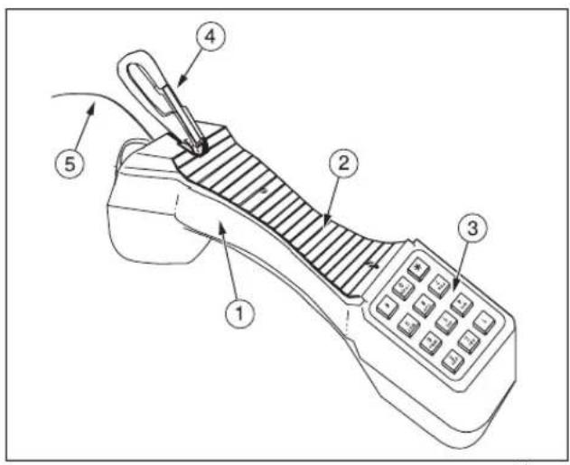
Figure 1. Physical Characteristics
① The case is designed to give rugged service and withstand the rough handling and shocks normally associated with craft tools.
② The back of the handgrip is contoured and has a non-slip surface, freeing both hands while the Portable Test Telephone rests on the shoulder.
③ The keypad has 12 keys on a black plastic bezel that is recessed into the receiver end of the housing. The recessed bezel protects the keypad and prevents accidental key presses.
④ The spring-loaded belt clip ensures a secure connection to a belt loop or D-ring. The belt clip may be replaced in the field (see Belt Clip Replacement).
⑤ The Portable Test Telephone is equipped with one of two cord configurations. The line cords may be replaced in the field.
Handgrip Controls
See Figure 2.

flowchart
graph LR
    A["Transmitter"] --> B["1"]
    B --> C["2"]
    B --> D["3"]
    C --> E["Receiver"]
    D --> E
    style A fill:#f9f,stroke:#333
    style B fill:#ccf,stroke:#333
    style C fill:#cfc,stroke:#333
    style D fill:#fcc,stroke:#333
bdn02.eps
Figure 2. Handgrip Controls
① Last Number Redial Button: The LNR button serves as a last number dialed key. The number may be redialed in either pulse or tone mode as selected by the PULSE/TONE switch. The last number dialed may be up to 18 digits long.
Note
The redial memory has a 15-minute time limit after the TS19 has been disconnected from a working telephone line. After 15 minutes, the number will be lost from memory.
② HI Z/RING/TALK Switch: This three-position slide switch is labeled as HI Z for high impedance monitoring, RING for ringer and low impedance monitoring, and TALK for talk.
- In the HI Z position, the TS19 is on hook with a high impedance coupling to the telephone line. This allows for telephone line monitoring without disrupting conversations, data or signaling.
- In the RING position, the TS19 is on hook with an electronic ringer connected to the telephone line. The TS19 is low impedance coupled to the line for monitoring of optional line identification tones. Also, the TS19 provides enhanced receive levels.
- In the TALK position, the TS19 is off hook and may be used for dialing and talking. In this mode, the TS19 performs as an ordinary telephone.
③ PULSE/TONE switch: This two-position slide switch labeled PULSE/TONE, is located on the inside of the handgrip just below the receiver. The switch selects the signaling output. TONE for DTMF of PULSE for dial pulse.
Keypad Controls and Indicators
See Figure 3.
Keys: The 12 standard keyswill send either DTMF tones or dial pulses, depending on the PULSE/TONE switch setting.
Polarity LED: This red LED is located just below the keypad. The LED indicates polarity (see "Polarity Check"). The red LED lights if the red test lead is connected to the Tip (positive) side and the black test lead is connected to the Ring (negative) side.
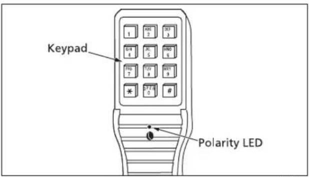
Figure 3. Keypad
Cords
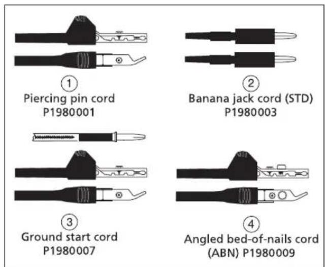
See Figure 4.
The TS19 comes with either a standard cord or an angled bed-of nails cord (see ② and ④ below). The line cord can be replaced in the field (see "Line Cord Replacement").
bdn04.eps
Figure 4. Line Cords
Various cord types may be ordered for field replacement:
① Piercing Pin Cord: This cord is equipped with a modular plug on one end, and has two five and one half foot long fabric covered leads, one red and one black. Each conductor is fitted with an alligator clip offset 20 degrees to minimize clip shorting. The clips have insulation piercing spikes and a neoprene boot. Cord Number: P1980001.
② Banana Jack Cord (STD): This is the standard cord. This cord is equipped with a modular plug at one end and two banana jacks at the other with alligator clip adapters. Cord Number: P1980003.
③ Ground Start Cord: This cord consists of two conductors with alligator clips. In addition, the red (ring) conductor has a banana jack attached. This jack is located six inches below the Portable Test Telephone and is partially covered by the outer fabric of the cord. A separate cord is also included. This cord is 36 inches long with a banana plug on one end and an alligator clip on the other. Cord Number: P1980007.
④ Angled Bed-of-Nails Cord (ABN): This cord is similar to the standard cord (STD), except that each alligator clip is equipped with a "bed-of-nails" and an insulation piercing spike. Cord Number: P1980009.
Operation
Warning
When connecting to metallic network wires, always handle alligator clips by the insulated boots.
Monitoring: Move the HI Z/RING/TALK switch to HI Z and connect the line leads to the telephone line under test. Monitoring may now be done without disrupting traffic.
Polarity Check: Move the HI Z/RING/TALK switch to TALK. Connect the line leads to the telephone line under test. The red LED lights if the red test lead is connected to the Tip (positive) side and the black test lead is connected to the Ring (negative) side.
Dialing:
1 Move the PULSE/TONE Switch to PULSE or TONE, depending on the type of dial signaling required. Move the HI Z/RING/TALK switch to HI Z. Connect the line cord clips to the telephone line. Listen to verify that the telephone line is idle.
2 Move the HI Z/RING/TALK switch to TALK and verify that dial tone is received (when finished). Enter the desired number to be called on the keypad. If tone signaling is selected, the tones for each digit are generated as each key is pressed. If rotary dial pulse signaling is selected, the desired number may be entered at any rate on the keypad; digits will automatically be pulsed out at the correct rate. To end the call, move the HI Z/RING/TALK switch to the HI Z position.
Last Number Redial: The last number dialed can be automatically redialed with the PULSE/TONE switch set to PULSE or TONE. Use the following procedure for a number up to 18 digits long:
1 Go on hook (move the HI Z/RING/TALK switch to the HI Z position) for at least 12 second.
2 Move the HI Z/RING/TALK switch back to the TALK position.
3 Press the LNR button and the number will be automatically redialed.
Note
The redial memory has a 15 minute time limit after the Portable Test Telephone has been disconnected from a working telephone line.
After 15 minutes, the number will be lost from memory.
Electronic Ringer (On/OFF): Move the HI Z/RING/TALK switch to RING and connect line leads to the telephone line. The piezo-electric transducer electronic ringer will "ring" whenever it detects ringing voltage on the line. Answer the call by moving the HI Z/RING/TALK switch to TALK. To disable the ringer, move the HI Z/RING/TALK switch to HI Z.
Troubleshooting
The following troubleshooting procedures are based largely on the audible click heard in the receiver of the TS19 when the two Portable Test Telephone leads are placed on battery potential and ground respectively, or across the terminal of an electrically charged capacitor. These clicks and other sounds can help you locate open circuits, shorts, crosses, and grounds.
To locate a short circuit: Open one side of the telephone line and place the test set in the loop — one lead to each side of the opened line. On the CO side of the fault, a loud click will be heard. On the field side of the fault, no click will be heard.
To locate an open circuit: Bridge the test set across the circuit line — one test lead on tip, the other on ring. Moving away from the CO, the fault is at the point where the loud click disappears.
To verify continuity: Place one of the line leads on a local ground and the other on the conductor in question. On a good Ring conductor, a click will be heard. On a good Tip conductor, an inductive hum will be heard (due to the difference in ground potential between the CO ground and the local ground).
Warning
When testing circuits close to the battery source, the clicks may be loud enough to hurt your ear if the receiver is held too tightly against the ear. The TS19 is designed to rest comfortably on the shoulder with the receiver away from the ear. It should be used in this position when listening for clicks.
Maintenance
Warning
Disconnect clips from any metallic connections before performing any maintenance. Read all instructions completely and understand possible hazards to end user if not performed by authorized service personnel.
Caution
Do not use CRC Cable Clean® or any similar chlorinated solvent on the TS19. Doing so will damage the TS19 Test Telephone.
Belt Clip Replacement
The ordering number for the replacement belt clip is P3218249. To replace the belt clip assembly:
1 Place the TS19 on a firm and level working surface with the keypad up.
2 Remove the two screws which secure the belt clip to the TS19's plastic grip (one screw also secures the strain relief cord). Remove and discard the old belt clip.
3 Position the new belt clip so that its screw mounting holes line up with the mounting holes in the TS19. Insert the screws and tighten. Make sure the strain relief for the cord is properly reinstalled.
Line Cord Replacement
To replace the line cord:
Warning
Disconnect from telephone network when replacing line cord.
1 Place the TS19 on a firm and level working surface with the keypad up.
2 Remove the screw and the strain relief cord.
3 Depress the plastic tang on the modular plug of the line cord where it enters the TS19's modular jack and gently pull the plug and cord free from the jack. Discard the cord.
4 Insert the modular plug of the replacement cord into the TS19's modular jack and listen for a click. The click indicates that the plug has "locked" into position with its tang properly engaged to prevent accidental removal.
5 Reinstall the screw for the strain relief cord.
Specifications
| Electrical | |
| Loop Limit | 2.4 kΩ maximum at 48 VDC (nominal 15 mA minimum loop current) |
| DC Resistance (Talk Mode) | 150 Ω typical at 80 mA current |
| AC Impedance (Monitor Mode) | Low impedance (Ring position) 600 Ω at 1 KHz typicalHigh impedance (HI Z position) 100 kΩ minimum at 1 KHz |
| Rotary Dial Output | |
| Pulsing Rate | 10 pps +0.5 pps |
| Percent Break | 60 % ± 2 % |
| Interdigit Interval | 800 ms typical |
| Leakage During Break | >50 kΩ |
| DTMF Output | |
| Tone Frequency Error | ±1 % maximum |
| Level per Tone Pair | +2 dBm maximum, -8 dBm minimum |
| High versus Low Tone Difference 4 dB maximum | |
Physical
Length 8.75 in (22.2 cm)
Width 2.375 in (6.03 cm)
Height 3.375 in (8.57 cm)
Weight 10.8 oz (.307 kg) maximum
Environmental
Temperature Operating: -5 °C to +40 °C
Storage: -40 °C to +66 °C
Drop 1 m, 4 times
Altitude To 3,000 m (10,000 ft) maximum
Relative Humidity
10 % to 80 % (non-condensing)
Regulatory Standards Used
47 CFR Part 15, Subpart B
ICES-003 Issue 3
AS/NZS 3548
EMC Directive 89/336/EEC, EN 55022:98, EN 61326:97, A1:98 Annex C, EN 61000-4-2, EN 61000-4-3
LV Directive 73/23/EEC, EN 610010.1 (1993)
Certifications and Compliance

Conformité Européenne. Conforms to relevant European Union directives.

CAN/CSA-C22.2 No. 60950-1-03
CAN/CSA-C22.2 No. 1010.1-92 + CSA-C22.2 No. 1010.1B-97, UL/ANSI 3111-1
Specifications subject to change without notice.
- Portable Test Telephone
- LIMITED WARRANTY AND LIMITATION OF LIABILITY
- TS®19 Portable Test Telephone
- Contents
- Introduction
- Registration
- Contacting Fluke Networks
- Safety Information
- Warning
- Physical Characteristics
- Handgrip Controls
- Note
- Keypad Controls and Indicators
- Cords
- Operation
- Dialing:
- Troubleshooting
- Maintenance
- Caution
- Belt Clip Replacement
- Line Cord Replacement
- Physical
- Environmental
- Regulatory Standards Used
- Certifications and Compliance
Brand : FLUKE
Model : TS 19
Category : Wi-Fi repeater