
HMK1P-800D-FT420X2 - Solar installation HAIER - Free user manual and instructions
Find the device manual for free HMK1P-800D-FT420X2 HAIER in PDF.


| Product Type | Smart Balcony Solar Kit (LUMENIA) |
| Model | HMK1P-800D-FT420X2 |
| Brand | Haier |
| Solar Panel Dimensions | 1722 x 1134 x 30 mm |
| Micro Inverter Dimensions | 268 x 250 x 42 mm |
| Weight (Total Kit) | Exceeds 20 kg |
| Rated Power | 800 W (adjustable to 600 W) |
| Input Voltage | DC from PV panels |
| Output Voltage | AC grid-tied |
| Connectivity | WiFi (2.4 GHz) via Nahui Energy App |
| Mounting Type | Balcony railing hooks and brackets |
| Installation Requirements | Two persons recommended; avoid rain/wind; use qualified technician |
| Safety Features | LED status indicator; grid approval required; overvoltage protection |
| App Compatibility | Nahui Energy (iOS/Android) |
| Warranty | Refer to manufacturer; modifications void warranty |
| Included Accessories | Solar panels (2), microinverter, brackets, hooks, cables, rubber mat, installation tools |
| Maintenance | Regularly check screws and stability after adverse weather |
| Operating Temperature | Not specified; general outdoor use |
| Certificate | Grid-tied compliance per local regulations |
Frequently Asked Questions - HMK1P-800D-FT420X2 HAIER
User questions about HMK1P-800D-FT420X2 HAIER
0 question about this device. Answer the ones you know or ask your own.
Ask a new question about this device
Download the instructions for your Solar installation in PDF format for free! Find your manual HMK1P-800D-FT420X2 - HAIER and take your electronic device back in hand. On this page are published all the documents necessary for the use of your device. HMK1P-800D-FT420X2 by HAIER.
USER MANUAL HMK1P-800D-FT420X2 HAIER
NOTE:
Nominal Power of PV Panels and Max AC Power of microinverter depends on the specific purchased model.
STAMP:
Haier
[EN]
Smart Balcony Solar Kit - LUMENIA
HMK1P-600D-FB
HMK1P-800D-FB
HMK1P-600D-FT420X2
HMK1P-800D-FT420X2
HMK1P-600D-FT440X2
HMK1P-800D-FT440X2

QR Code for manuals in multi-language

Scan the QR code to download the
user manual in other languages

NOTE
- Read this user guide carefully before installing as it contains important instructions for the installation process.
- When installing the product, you and/or your assigned technician should always ensure safe conditions. Avoid installation in rain, wind, or adverse weather conditions. Check a reliable weather forecast before installing.
- Never install the product alone, but preferably seek help from qualified technicians, as the weight of the product exceeds 20 kg. If you seek the help of non-techies, make sure that the person helping is an adult. During installation, make sure that there are no people, pets, or animals nearby. Cancel the process if there is something damaging underneath.
- After installation, regularly check the screws to make sure they have not loosened. Regularly check the overall stability of the product (especially after adverse weather conditions). If instability is suspected, a technician must be called in immediately.
• Ininstances of uncertainty, seek assistance from a qualified technician or reach out to our customer service for guidance. You can find our local contact details visiting this web page: https://eur.nahui-newenergy.com/services.html
Haier
Haier
V2.2 EN
Quick Installation Guide for Smart Balcony Solar Kit
LUMENIA
1. Accessories

| Serial no. | Designation Image Size Quantity | |||
| 1 | Solar panel |  | 1722 x 1134 x 30mm | 1×2 |
| 2 115 | 5mm/4mm profile | |||
| 3 | Rail connector |  | 545mm 2×2 | |
| 4 | Crossbar |  | 1110mm 1×2 | |
| 5 M8x20 6×88 screw |  | |||
| 6 M6x20 2×MG screw |  | |||
| 7 M8x48 1×88 (Far Micro inverter) |  | |||
| Serial no. | Designation Image Size | Quantity | ||
| 8 | M6 x 90mm screw |  | M6x90 | 2×2 |
| 9 | M6 x 20mm screw | M6x20 | 10×2 | |
| 10 2×2 | Rolling hook |  - - Screws are included in the accessories - - Screws are included in the accessories | 160 x 110 x 35 mm | |
| 11 | Micro inverter |  | 268 x 250 x 42 mm | 1 |
| 12 | DC Cable |  | 1m | 1 pair |
| 13 | AC Cable |  | 5m | 1 |
| 14 2×2 | Strap | 4.6 x 250mm | ||
| 15 | Installation tools |  | 137×25×5mm | 2 |
| 16 | Rubber mat |  | 195×35mm | 2×2 |
2. Installation Instruction
STEP 1. Mounting Balcony Bracket
STEP 1.1 - Mounting the aluminum profiles on the solar panel
First, please connect the vertical profiles with the provided holes on the solar panel.

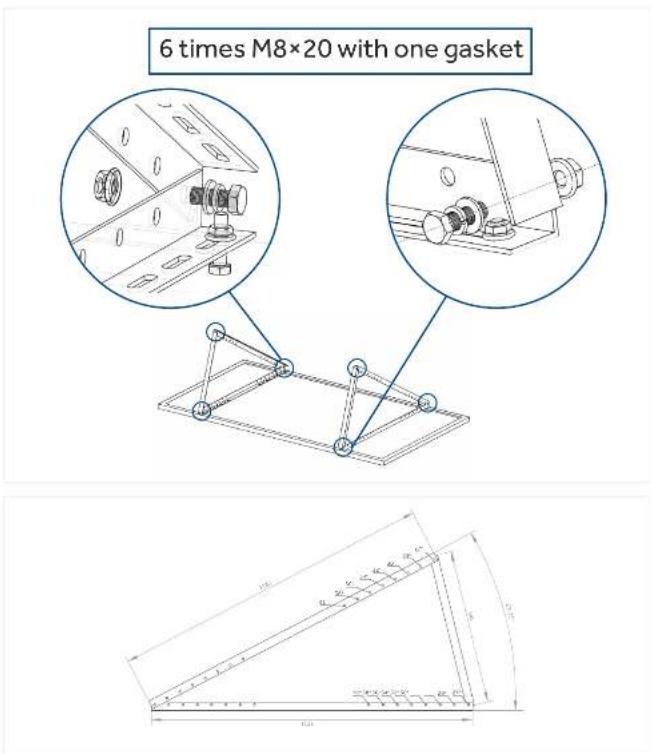
STEP 1.2 - Mounting the triangular bracket
Use M8 screws to connect the triangular bracket. (Attach the Aluminum profile first, then the Rail connector) The suspension angle of the PV module can be adjusted through different holes.
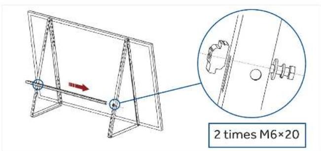
STEP 1.3 - Mounting the crossbar
The crossbar gives the additional stability of the substructure and is usually used to mount the micro-inverter directly.
Pretighten the M6 screws and slider, then slide the slider into the crossbar, finally tighten the M6 screws and slider. Repeat the above operation to fix the crossbar.
When doing so, observe the required cable lengths. Depending on your local requirements, you can mount the crossbar in different positions. (The lower the installation position, the better the stability).
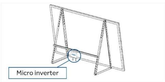
STEP 1.4 - Installation of Microinverters
Please use 2 x M8 screws (for micro inverter) on the crossbar to fix the inverter.
Before installing the micro inverter, record the information on the label on the microinverter. (required for subsequent distribution)
Follow the procedure 1.1-1.3 to install another set of brackets
CAUTION
Before installing the microinverter, record the information on the label on the microinverter (required for subsequent configurations)
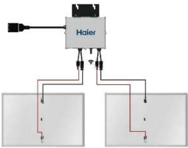
STEP 2. Connect the DC Cable with Micro Inverter
Connect the PV panel with the micro inverter via the MC4 connector on the DC cable.
flowchart
graph TD
    A["Input"] --> B["Haier"]
    B --> C["Panel 1"]
    B --> D["Panel 2"]
    B --> E["Output"]
    style B fill:#ccc,stroke:#333
    style C fill:#fff,stroke:#333
    style D fill:#fff,stroke:#333
    style E fill:#fff,stroke:#333
STEP 3. Connect The AC Cable of The Micro Inverter
Connect the AC cable to the micro inverter via male and female clamp
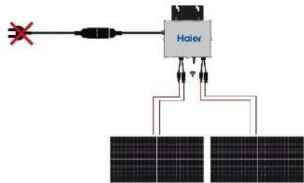
flowchart
graph TD
    A["Input"] --> B["Heier"]
    B --> C["Solar Panel 1"]
    B --> D["Solar Panel 2"]
    B --> E["Solar Panel 3"]
    B --> F["Solar Panel 4"]
    style A fill:#f9f,stroke:#333
    style B fill:#ccf,stroke:#333
    style C fill:#dfd,stroke:#333
    style D fill:#dfd,stroke:#333
    style E fill:#dfd,stroke:#333
    style F fill:#dfd,stroke:#333
CAUTION
DO NOT CONNECT AC PLUG TO THE SOCKET BEFORE SETTING UP WIFI CONNECTION.
STEP 4. Set up The Fixed Network


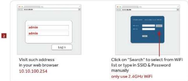

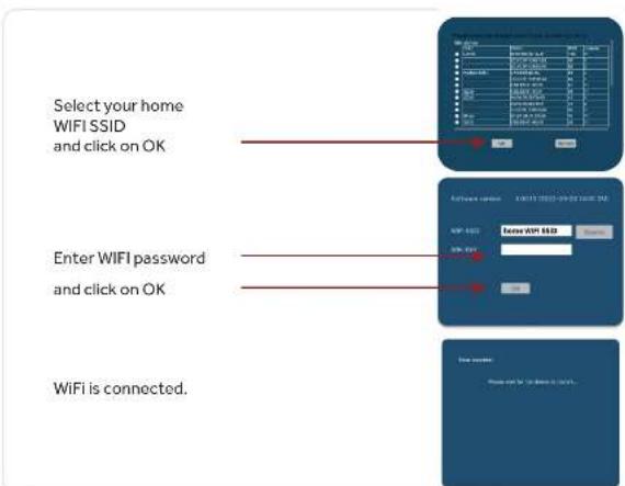
| Original FM RSSI | 6-level FM RSSI Wi-Fi RSSI | |
| 40 to 45 | -50 | Excellent |
| 30 to 39 | -60 | Very good |
| 20 to 29 | -70 | Good |
| 10 to 19 | -80 | Low |
| 1 to 9 | -90 | Very low |
| 0 | 0 | No signal |
ADJUSTING POWER 600W AND 800W (Refer to local grid-connection regulations)

NOTICE
If there is a change in the policy of the place where the product is used, or if the user's needs change, the output power needs to be changed, please make sure to disconnect AC and follow these steps.
- Enter the link on your computer to download "power_adjust.zip" https://pcs-public-read-write.oss-cn-qingdao.aliyuncs.com/user-guide/power_adjust.zip

ропан дэја
07
- Open the ZIP file, find the power_adjust guide document, follow its step
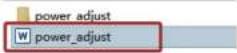
STEP 5. Mounting the railing hooks

- Place the hook on the railing, adjust the bar diameter and lock the bolt at A.
- Connect the hook to the triangular bracket by screw at B.
- Hang the bracket on the railing (two persons are required to work on it).
- Attach the hooks to the railing with the screw at C.

CAUTION
• These installation instructions are intended exclusively for this product.
• It is essential to follow the sequence of steps.
- Do not perform the electrical installation until the assembly is complete.
• Any type of modification to the mounting kit will void the warranty.
- Please do not mount the PV panels vertically.
- Please wear gloves during installation
- Cable Tie can be used to secure brackets in windy areas
OR
STEP 6. Insert the AC cable plug into the socket
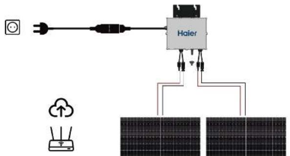
Data will start uploading to server after 10 minutes.
It could take more time depending on your internet connection.
STEP 7. Micro Inverter Instruction Manual
STEP 7.1 - Open Nahui Energy App
Search for Nahui Energy in App Store or Google Play
NOTICE
User can scan the QR code below for app download.
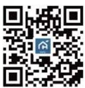
Nahui Energy

STEP 7.2 - Login or Register
Enter the information and check that you have read and agreed to the User Agreement and Privacy Policy, then you can enter the App.
NOTICE
When registering, please select your region (country) correctly, and it cannot be changed after registration.
Register:

flowchart
graph LR
    A["Login"] --> B["Register"]
    B --> C["Enter Verification Code"]
    C --> D["Set Password"]
Login:

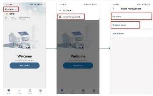
STEP 7.3 - Home Management
The App will default to creating a family, and you can also create a new one by yourself.
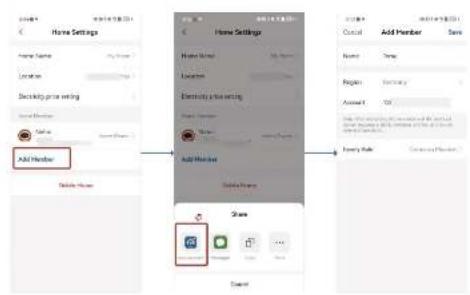
STEP 7.4 - Add Member
Fill in the information of the family member (please select exactly the registration region of the added account), and the other party can add it successfully after agreeing.

NOTICE
This step is not required.
STEP 7.5 - Add Device
Click "Add Device" and scan the QR code (called "Connect the app") on the Micro inverter.

NOTICE
- If you create or join more than one family in the app, first switch to the family you want to add the device to.
- If your device is reset or you have modified your home WiFi, you will need to re-set up the fixed network for micro inverter (refer to step 4) without operating within the app.

flowchart
graph LR
    A["Welcome"] --> B["Add Device"]
    B --> C["Add Password"]
    C --> D["Add Address"]
    D --> E["Add Password"]
    style A fill:#f9f,stroke:#333
    style B fill:#ccf,stroke:#333
    style C fill:#cfc,stroke:#333
    style D fill:#fcc,stroke:#333
    style E fill:#ffc,stroke:#333
The QR code location is shown in the image:

STEP 7.6 - Finish setting
It's all set!
Enjoy your balcony solar renewable energy!

STEP 7.7 - Data viewing
If you also want to see the power generation data of the system, you can view it as follows:
- Click the icon of the inverter to view the real-time power of the inverter, the power generation data of the day and other information.
- Click "Analysis" to enter the data dashboard, you can view the power generation, electricity consumption related statistics in the household for the day and more information.
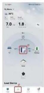


bar
| Metric | Value | | :--- | :--- | | Temperature (°C) | 7.0 | | Temperature (°C) | 96 | | Temperature (°C) | 1.8 | | Production (units) | 7.00 | | Production (units) | 80.01 | | Production (units) | 7.00 | | Production (units) | 0.2 | | Production (units) | 0.3 | | Production (units) | 0.2 | The chart displays the 'Temperature (°C)' and 'Production (units)' values for the '25°C' data series. The 'Population (units)' is also shown on the right.COMMISSIONING
WARNING
CONNECT MICRO INVERTER TO THE ELECTRICAL UTILITY GRID ONLY AFTER RECEIVING PRIOR APPROVAL FROM THE UTILITY COMPANY.
WARNING
ENSURE THAT ALL AC AND DC WIRING IS CORRECT. ENSURE THAT NONE OF THE AC AND DC WIRES IS PINCHED OR DAMAGED. ENSURE THAT ALL JUNCTION BOXES ARE PROPERLY CLOSED.
Operating Instructions
The micro inverter is powered on when sufficient DC voltage from the module is applied. The status LED will start flashing after sufficient DC power is applied as an indication that the micro inverter is working.
| Flashing per 1 sec | Flashing per 2 sec | Flashing per 4 sec | |
| WiFi Connected AC connected | WiFi Connected Inverter Standby | WiFi Connected Inverter Working | |
| WiFi not connected AC disconnected | Inverter Alert | Inverter Alert | |
| WiFi not connected AC connected | WiFi not connected Inverter standby | WiFi not connected Inverter working |
- Haier
- NOTE
- Accessories
- Installation Instruction
- STEP 1. Mounting Balcony Bracket
- STEP 1.2 - Mounting the triangular bracket
- STEP 1.3 - Mounting the crossbar
- STEP 1.4 - Installation of Microinverters
- CAUTION
- STEP 2. Connect the DC Cable with Micro Inverter
- STEP 3. Connect The AC Cable of The Micro Inverter
- STEP 4. Set up The Fixed Network
- NOTICE
- STEP 7. Micro Inverter Instruction Manual
- STEP 7.3 - Home Management
- STEP 7.4 - Add Member
- STEP 7.5 - Add Device
- STEP 7.6 - Finish setting
- STEP 7.7 - Data viewing
- COMMISSIONING
- WARNING
- Operating Instructions
Brand : HAIER
Model : HMK1P-800D-FT420X2
Category : Solar installation