
Festa FS352G - Switch TP-LINK - Free user manual and instructions
Find the device manual for free Festa FS352G TP-LINK in PDF.


| Product Type | Unmanaged Network Switch |
| Brand | TP-Link |
| Model | Festa FS352G |
| Ports | 5 x 10/100/1000 Mbps RJ45 |
| Switching Capacity | 10 Gbps |
| Forwarding Rate | 7.44 Mpps (packets per second) |
| MAC Address Table | 2K entries |
| Auto-Negotiation | Yes (speed and duplex) |
| Auto-MDI/MDIX | Yes (crossover detection) |
| Standards | IEEE 802.3, 802.3u, 802.3ab, 802.3x |
| Dimensions (W x D x H) | 100 x 98 x 25 mm (3.9 x 3.9 x 1.0 in) |
| Weight | 200 g (7.1 oz) |
| Power Supply | External power adapter (5V DC, 0.6A) |
| Power Consumption | Max 2.5 W |
| LED Indicators | Power, Link/Act per port |
| Mounting | Desktop or wall-mountable (holes on bottom) |
| Operating Temperature | 0°C to 40°C (32°F to 104°F) |
| Storage Temperature | -40°C to 70°C (-40°F to 158°F) |
| Operating Humidity | 10% to 90% non-condensing |
| Safety Certifications | CE, FCC, RoHS |
| Maintenance | Clean with soft dry cloth; do not use liquids |
| Spare Parts / Repairability | Not user-serviceable; no spare parts available |
| Warranty | Limited lifetime warranty (TP-Link policy) |
Frequently Asked Questions - Festa FS352G TP-LINK
User questions about Festa FS352G TP-LINK
0 question about this device. Answer the ones you know or ask your own.
Ask a new question about this device
Download the instructions for your Switch in PDF format for free! Find your manual Festa FS352G - TP-LINK and take your electronic device back in hand. On this page are published all the documents necessary for the use of your device. Festa FS352G by TP-LINK.
USER MANUAL Festa FS352G TP-LINK
This User Guide provides information for centrally managing TP-Link devices via the Festa Cloud-Based Controller. Please read this guide carefully before operation.
Intended Readers
This User Guide is intended for network managers familiar with IT concepts and network terminologies.
Conventions
When using this guide, notice that:
■ Features available in the Festa Cloud-Based Controller may vary due to your region, controller version, and device model. All images, steps, and descriptions in this guide are only examples and may not reflect your actual experience.
■ The information in this document is subject to change without notice. Every effort has been made in the preparation of this document to ensure accuracy of the contents, but all statements, information, and recommendations in this document do not constitute the warranty of any kind, express or implied. Users must take full responsibility for their application of any products.
This guide uses the specific formats to highlight special messages. The following table lists the notice icons that are used throughout this guide.
In this guide, the following conventions are used:
Controller Stands for the Festa Cloud-Based Controller.
Gateway Stands for the Festa Gateway.
Switch Stands for the Festa Switch.
AP Stands for the Festa AP.

Note
The note contains the helpful information for a better use of the Controller.

Configuration Guidelines
Provide tips for you to learn about the feature and its configurations.
More Information
■ For technical support, the latest version of the User Guide and other information, please visit https://www.tp-link.com/support/?type=smb.
■ To ask questions, find answers, and communicate with TP-Link users or engineers, please visit https://community.tp-link.com/business to join TP-Link Community.
CONTENTS
About this Guide
Festa Cloud-Based Controller Solution Overview
Overview....2
Core Components 3
Get Started with Festa Cloud-Based Controller
Set Up Your Festa Cloud-Based Controller 6
Navigate the Controller UI....7
Configure Controller Settings....11
System Settings....11
Controller Settings....12
Manage Account 15
Introduction to User Accounts and Role 15
Create and Manage User Accounts.... 15
Manage and Configure Sites
Create Sites....18
Configure Site Settings....21
Site Configuration....21
Services....22
Advanced Features 23
Device Account 25
Manage, Configure, and Monitor Devices
Adopt Devices....28
Introduction to the Devices Page 30
Configure and Monitor the Gateway....34
Configure the Gateway....34
Monitor the Gateway....43
Configure and Monitor Switches....46
Configure Switches 46
Monitor Switches 68
Configure and Monitor APs....72
Configure APs....72
Configure the Network with the Festa Cloud-Based Controller
Configure Wired Networks 94
Set Up an Internet Connection 94
Configure LAN Networks....112
Configure Wireless Networks....125
Set Up Basic Wireless Networks.... 125
Advanced Settings 130
WLAN Schedule....131
802.11 Rate Control.... 132
MAC Filter 133
Multicast/Broadcast Management 134
Network Security 136
ACL 136
URL Filtering....145
Transmission....149
Routing....149
Bandwidth Control....152
Port Forwarding 154
Configure VPN....157
VPN 157
VPN User....184
Create Profiles....187
Time Range 187
Groups 189
Rate Limit....191
Authentication....194
Portal....194
RADIUS Profile....199
Services 202
Dynamic DNS 202
SNMP 204
SSH 205
IPTV....206
Monitor the Network
View the Status of Network with Dashboard....210
Page Layout of Dashboard....210
Explanation of Widgets....211
Monitor the Network with Map 213
Topology......213
Heat Map....214
View the Statistics During Specified Period with Insights....220
Past Portal Authorizations 220
VPN Status....220
View and Manage Logs 224
Alerts 224
Events....225
Notifications....226
Monitor the Network with Tools....227
Network Check 227
Terminal 228
Monitor and Manage the Clients
Manage Wired and Wireless Clients in Clients Page 231
Introduction to Clients Page 231
Using the Clients Table to Monitor and Manage the Clients 231
Using the Properties Window to Monitor and Manage the Clients.... 233
Manage Client Authentication in Hotspot Manager 238
Dashboard 238
Authorized Clients 238
Vouchers 239
Form Auth Data 242
Operators 243
Festa Cloud-Based Controller Solution Overview
Festa Cloud-Based Controller Solution offers centralized and efficient management for configuring small and mid-size business networks comprised of security gateways, switches, and wireless access points.
With a reliable network management platform powered by the TP-Link Festa Cloud-Based Controller, you can develop comprehensive, software-defined networking across demanding, high-traffic environments with robust wired and wireless solutions.
The chapter includes the following sections:
• 1 Overview
• 2 Core Components
1 Overview
Festa Cloud-Based Controller Solution is designed to provide business-class networking solutions for demanding, high-traffic environments such as small businesses, home offices, and cafes. It simplifies deploying and managing large-scale enterprise networks and offers easy maintenance, ongoing monitoring, and flexible scalability.
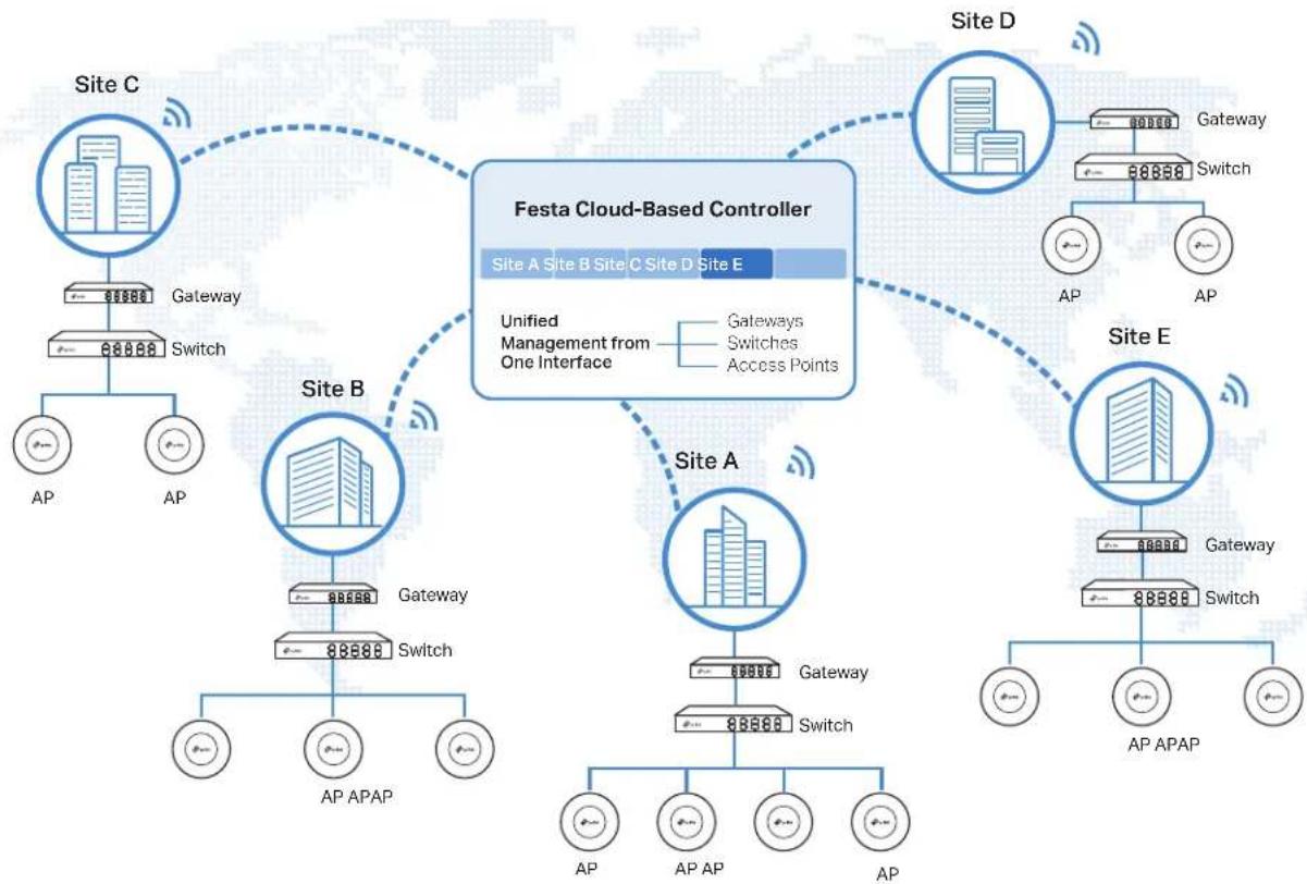
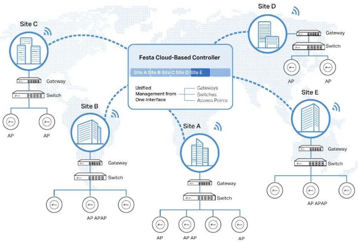
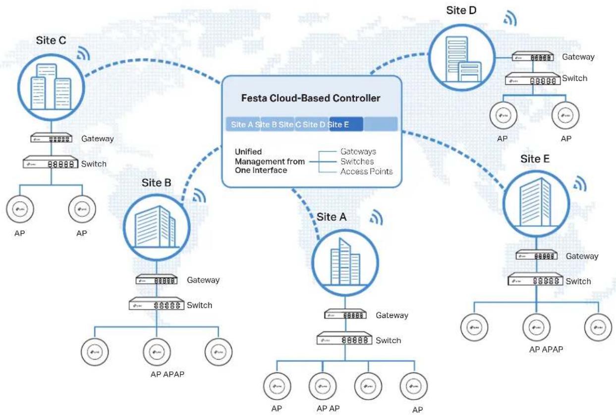
This figure shows a sample architecture of a Festa enterprise network:
flowchart
graph TD
    subgraph Site A
        A1["Site A"] -->|Gateway| A2["Site B"]
        A2 -->|Switch| A3["AP"]
        A2 -->|AP APAP| A4["AP"]
    end

    subgraph Site B
        B1["Site B"] -->|Gateway| B2["Site C"]
        B2 -->|Switch| B3["AP"]
        B2 -->|AP APAP| B4["AP"]
    end

    subgraph Site C
        C1["Site C"] -->|Gateway| C2["Site D"]
        C2 -->|Switch| C3["AP"]
        C2 -->|AP APAP| C4["AP"]
    end

    subgraph Site D
        D1["Site D"] -->|Gateway| D2["Site E"]
        D2 -->|Switch| D3["AP"]
        D2 -->|AP APAP| D4["AP"]
    end

    style Site A fill:#f9f,stroke:#333
    style Site B fill:#f9f,stroke:#333
    style Site C fill:#f9f,stroke:#333
    style Site D fill:#f9f,stroke:#333
    style Site E fill:#f9f,stroke:#333
The interconnected elements that work together to deliver a unified enterprise network include: Festa Cloud-Based Controller, gateways, switches, access points, and client devices. Beginning with a base of client devices, each element adds functionality and complexity as the network is developing, interconnecting with the elements above and below it to create a comprehensive, secure wired and wireless solution.
The Festa Cloud-Based Controller is a command center and management platform at the heart of the network. With a single platform, the network administrators configure and manage enterprise networks comprised of gateways, switches, and wireless access points in batches. This unleashes new levels of management to avoid complex and costly over-provisioning.
2 Core Components
A Festa network consists of the following core components:
■ Festa Cloud-Based Controller — A command center and management platform at the heart of network solution for the enterprise. With the single platform, the network administrators can configure and manage all the Festa products which have all your needs covered in terms of routing, switching and Wi-Fi.
■ Gateways — Boast excellent data processing capabilities and an array of powerful functions, including IPsec/OpenVPN/PPTP/L2TP VPN, Load Balance, and Bandwidth Control, which are ideal for the business network where a large number of users require a stable, secure connection.
■ Switches — Offer flexible and cost-effective network solution with powerful Layer 2 features and PoE options. Advanced features such as Access Control will satisfy advanced business networks.
■ Access Points — Satisfy the mainstream Wi-Fi Standard and address your high-density access needs with TP-Link's innovation to help you build the versatile and reliable wireless network for all business applications.
Festa Cloud-Based Controller
The Festa Cloud-Based Controller is deployed on the Festa Cloud server. With free cloud access, you can configure and manage the devices via the Cloud Service.
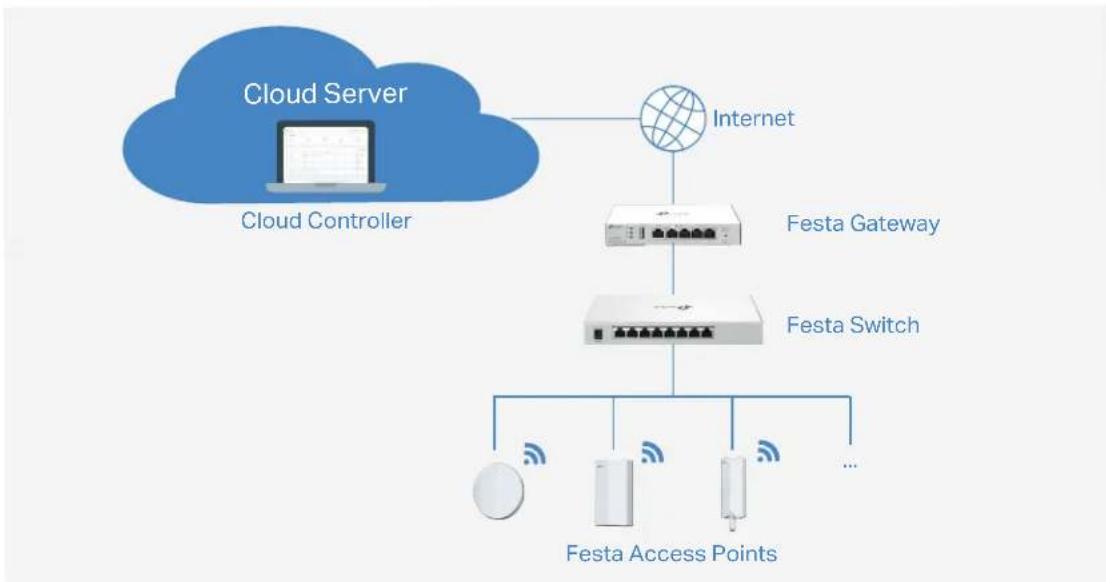
flowchart
graph TD
    A["Cloud Server"] --> B["Internet"]
    B --> C["Festa Gateway"]
    C --> D["Festa Switch"]
    D --> E["Festa Access Points"]
    D --> F["..."]
    style A fill:#333,stroke:#fff,color:#fff
    style B fill:#f9f,stroke:#000
    style C fill:#ccf,stroke:#000
    style D fill:#cfc,stroke:#000
    style E fill:#ffc,stroke:#000
    style F fill:#fcc,stroke:#000
In this guide, the Festa Cloud-Based Controller is referred to as the Controller.
Gateways
TP-Link's Festa Gateway supports Gigabit Ethernet connections on both WAN and LAN ports which keep the data moving at top speed. Including all the routing and network segmentation functions that a business gateway must have, the Festa Gateways will be the backbone of the network. Moreover,
the gateways provide a secure and easy approach to deploy site-to-site VPN tunnels and access for remote clients.
Switches
TP-Link's Festa Switch provides high-performance and enterprise-level security strategies and lots of advanced features, which is an ideal access-edge for the network.
Access Points
TP-Link's Festa Access Point provides business-class Wi-Fi with superior performance and range which guarantees reliable wireless connectivity for the network.
Get Started with Festa Cloud-Based Controller
This chapter guides you on how to get started with the Festa Cloud-Based Controller to configure the network. The chapter includes the following sections:
• 1 Set Up Your Festa Cloud-Based Controller
• 2 Navigate the Controller UI
• 3 Configure Controller Settings
- 4 Manage Account
1 Set Up Your Festa Cloud-Based Controller
Festa Cloud-Based Controller Solution is designed for scalable networks. Deployments and configurations vary according to actual situations. Understanding your network requirements is the first step when planning to provision any project. After you have identified these requirements, follow the steps below to initially set up the Cloud-Based Controller:
- Make sure that your devices can access the internet.
- Launch a web browser and enter https://festa.tplinkcloud.com in the address bar. Enter your TP-Link ID and password to log in. If you do not have a TP-Link ID, create a TP-Link ID first.
- Click Add Controller and register for a Festa Cloud-Based Controller. Follow the instructions to complete the setup process.
- Add devices with the serial number. Make sure the devices are online and in factory default.
Note:
Festa provides centralized management with free cloud access. Additional fees may apply for advanced features implemented in the future.
2 Navigate the Controller UI
As you start using the management interface of the Controller (Controller UI) to configure and monitor your network, it is helpful to familiarize yourself with the Controller UI.
Overview
Visual data keeps the network administrator informed about the accurate status of every network device and client on the wired and wireless network.
The Controller UI is grouped into task-oriented menus. These menus are located in the top right-hand corner and the left-hand navigation bar of the page. Note that the settings and features that appear in the UI depend on your user account permissions. The following image depicts the main elements of the Controller UI.
The elements in the top right corner of the screen give quick access to:
Organization:
Global View


Organization Management
Global View — Know the status of all your sites at a glance, manage the sites, configure the controller, and manage accounts of the controller.
Site View — Know the status of your network at a glance, gain insights, and manage network devices.
Hotspot Manager — Centrally monitor and manage the clients authorized by portal authentication.
Global Search Feature
Click 🔒 and enter the keywords to quickly look up the functions that you want to configure. You can also search for the devices by their MAC addresses and device names in the Site View.
My Account
Click the account icon 🔔 to display account information, Account Settings and Log Out. You can change your password on Account Settings.
More Settings
Click : to display About and Tutorial.
About: Click to display the controller version.
Tutorial: Click to view the quick Getting Started Guide which demonstrates the navigation and tools available for the Controller.
Global View
In the Global View, you can know the site status at a glance, manage sites, configure the controller, and manage accounts of the controller.
- Controller Overview — Know the real-time overall status of the Controller.
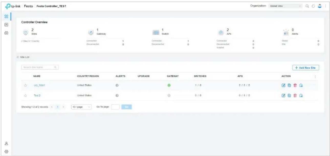
Site, which means logically separated network location, is the largest unit for managing networks with the Cloud-Based Controller. You can simultaneously configure features for multiple devices at a site.
- Site List—Create, edit, and manage all the sites to deploy the whole network.
- Site Bookmark – Click Bookmark to place frequently-used sites on the top of the list.
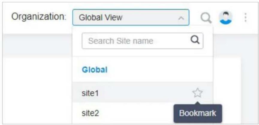
The left-hand navigation bar in the Global View provides access to:
| Dashboard displays a summarized view of the Controller. You can add and edit sites in the dashboard page and check the general status of different sites on the Controller. | |
| Devices | Devices displays all TP-Link devices discovered on the site and their general information. This list view can change depending on your monitoring need through customizing the columns. You can click any device on the list to reveal the Properties window for more detailed information of each device and provisioning individual configurations to the device. |
| Logs | |
| Logs shows log lines about varied activities of users, devices, and systems events, such as administrative actions and abnormal device behaviors. Comprehensive logs make historical information more accurate, readily accessible, and usable, which allows for proactive troubleshooting. You can determine alert-level events and enable pushing notifications. | |
| [3DYE] Account | Account allows you to add new users, check the basic information of the current user, and view the permissions of different roles. |
 Settings Settings | Settings allows you to provision and configure all your network devices on the same site in minutes and maintain the controller system for best performance. |
■ Site View
In the specific site, you can know the status of your network at a glance, gain insights, and manage network devices all in the platform.
- ISP Load and Widgets — Keep you informed of accurate, real-time status of every network device and client.
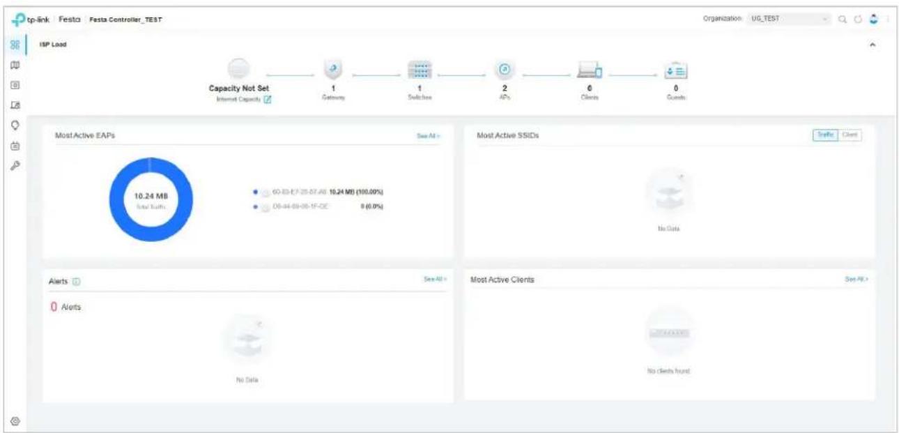
pie
| Category | Value | | -------- | ----- | | Most Active EAPs | 10.24 MB Total EAPs | | Most Active SSIDs | 60-83-E7 25-07-AE | | Most Active Clients | No Data |The left-hand navigation bar in the Site View provides access to:
| Dashboard displays a summarized view of the network status through different visualizations. The widget-driven dashboard is a powerful tool that arms you with real-time data for monitoring the network. | |
| Map generates the system topology automatically and you can look over the provisioning status of devices. By clicking on each node, you can view the detailed information of each device. You can also upload images of your location for a visual representation of your network. | |
| Devices displays all TP-Link devices discovered on the site and their general information. This list view can change depending on your monitoring need through customizing the columns. You can click any device on the list to reveal the Properties window for more detailed information of each device and provisioning individual configurations to the device. | |
| Clients displays a list view of wired and wireless clients that are connected to the network. This list view can change depending on your monitoring need through customizing the columns. You can click any clients on the list to reveal the Properties window for more detailed information of each client and provisioning individual configurations to the client. | |
| Insights displays a list of statistics of your network device, clients and services during a specified period. You can change the range of date in one-day increments. | |
| Log shows log lines about varied activities of users, devices, and systems events, such as administrative actions and abnormal device behaviors. Comprehensive logs make historical information more accurate, readily accessible, and usable, which allows for proactive troubleshooting. And you can determine alert-level events and enable pushing notifications. | |
| Tools provides various network tools for you to test the device connectivity and open Terminal to execute CLI or Shell commands. | |
| Settings allows you to provision and configure all your network devices on the same site in minutes and maintain the controller system for best performance. |
♥ 3 Configure Controller Settings
Controller Settings control the appearance and behavior of the Controller.
3.1 System Settings
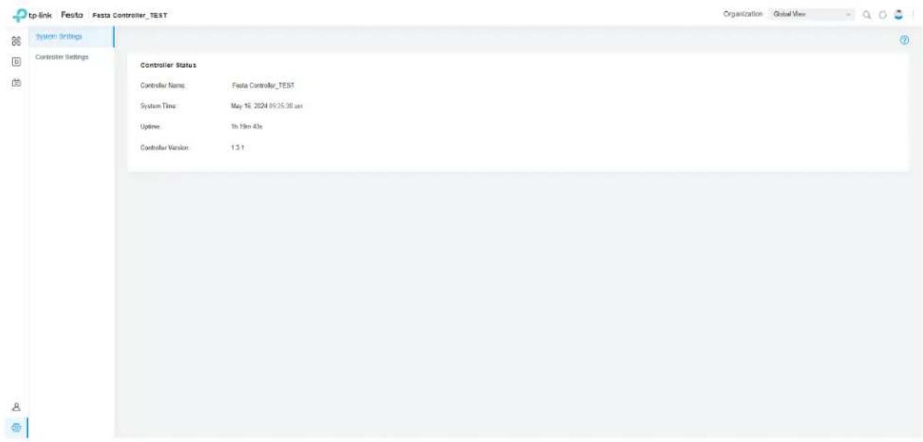
Select Global View from the drop-down list of Organization in the upper right corner. Go to Settings > System Settings. Information about the Controller Status will be shown, including Controller Name, System Time, Uptime, and Controller Version.
3.2 Controller Settings
Go to Settings > Controller Settings.
■ General Settings
In General Settings, configure the following parameters.
General Settings
Controller Name:
Festa Controller
Country/Region:
United States

Time Zone:
(UTC-05:00) Eastern Time (US & Canada)

Daylight Saving Time

Enable

- DST is applicable only when the device supports the feature. To make DST work properly, it is recommended to upgrade your devices to the latest firmware version.
- The DST configuration here only takes effect on the controller. To configure the DST for sites, go to the Site Configuration.
- With DST configured, the valid duration of Local User will be influenced accordingly.
Time Offset:
60 Minutes
Starts On:
Week
Day
Month
Time
1st
Sunday
January
00:00
①
Ends On:
Week
Day
Month
Time
1st
Sunday
January
00:00
①
Controller Name Specify the Controller Name to identify the controller.
| Country/Region | Select the Country/Region of the Controller according to your location. The configuration of Country/Region here only takes effect on the Controller. To configure the Country/Region for sites, go to the Site Configuration. |
| Time Zone | Select the Time Zone of the Controller according to your region. For controller settings and statistics, time is displayed based on the Time Zone. |
Daylight Saving Time Enable the feature if your country/region implements DST.
| Time Offset Select the time added in minutes when Daylight Saving Time starts. | |
| Starts On | Specify the time when the DST starts. The clock will be set forward by the time offset you specify. |
| Ends On | Specify the time when the DST ends.The clock will be set back by the time offset you specify. |
■ User Interface
In User Interface, configure the following settings to customize your interface.
User Interface
| Language: | English |
| Use 24-Hour Time: | |
| Statistic/Dashboard Timezone: | Site's |
| Fixed Menu: | |
| Dark Settings: | |
| Show Pending Devices: | i |
| Refresh Button: | |
| Cloud Firmware Detection: | i |
| Devices Update Notification: | i |
Language Select the language shown in the interface.
Use 24-Hour Time Enable the feature according to your preference.
Statistic/Dashboard Timezone Select the timezone shown in the Statistic/Dashboard.
Fixed Menu Enable the feature and the menu column will not come out.
Dark Settings Enable the feature and your interface will be in dark mode.
| Show Pending Devices | With this option enabled, the devices in Pending status will be shown, and you can determine whether to adopt them. With this option disabled, they will not be shown, thus you cannot adopt any new devices. |
| Refresh Button | Enable the option, the Refresh button will be shown on the top right of the interface. |
| Cloud Firmware Detection | This option is a global switch. If it is turned off, all cloud firmware detections will not be executed and prompted. |
| Devices Update Notification | With Devices Update Notification enabled, the controller will query the cloud for device firmware updates. |
■ App-Side Device Notifications
With this function enabled, the controller will send notifications to the app when your devices go online or offline.
App-Side Device Notifications

With this function enabled, the Controller will send notifications to the app when your devices go online or offline.
4 Manage Account
4.1 Introduction to User Account and Role
■ User
The Festa Cloud-Based Controller offers three levels of access available for users: main administrator, administrator, and viewer.
Multi-level administrative account presents a hierarchy of permissions for different levels of access to the controller as required. This approach ensures security and gives convenience for management.
Moreover, in the user account list of the main administrator, all accounts created by the main administrator will be displayed. The accounts created by each administrator will be hidden by default, making the interface more systematic and to the point.
Role
In Account > Role, three roles corresponding to the user accounts are displayed. You can view the details or permissions of each role.
- Main Administrator
The Main Administrator has access to all features.
The account who first launches the Controller will be the main administrator. It cannot be changed and deleted.
- Administrator
Administrators have no permission to some modules, mainly including global view logs and settings. Administrators can be created and deleted by the main administrator and administrators.
- Viewer
Viewers can view the status and settings of the network, and change the settings in Hotspot Manager.
The entrance to Account page is hidden for viewers, and they can be created or deleted by the main administrator and administrators.
4.2 Create and Manage User Accounts
The Controller automatically sets up the main administrator, which cannot be deleted. The main administrator can create, edit, and delete other levels of cloud user accounts.
To create and manage cloud user account, follow these steps:
- Select Global from the drop-down list of Organization in the top-right corner. Go to Account >User.
- Click Add New User.
3. Specify the parameters and click Invite.
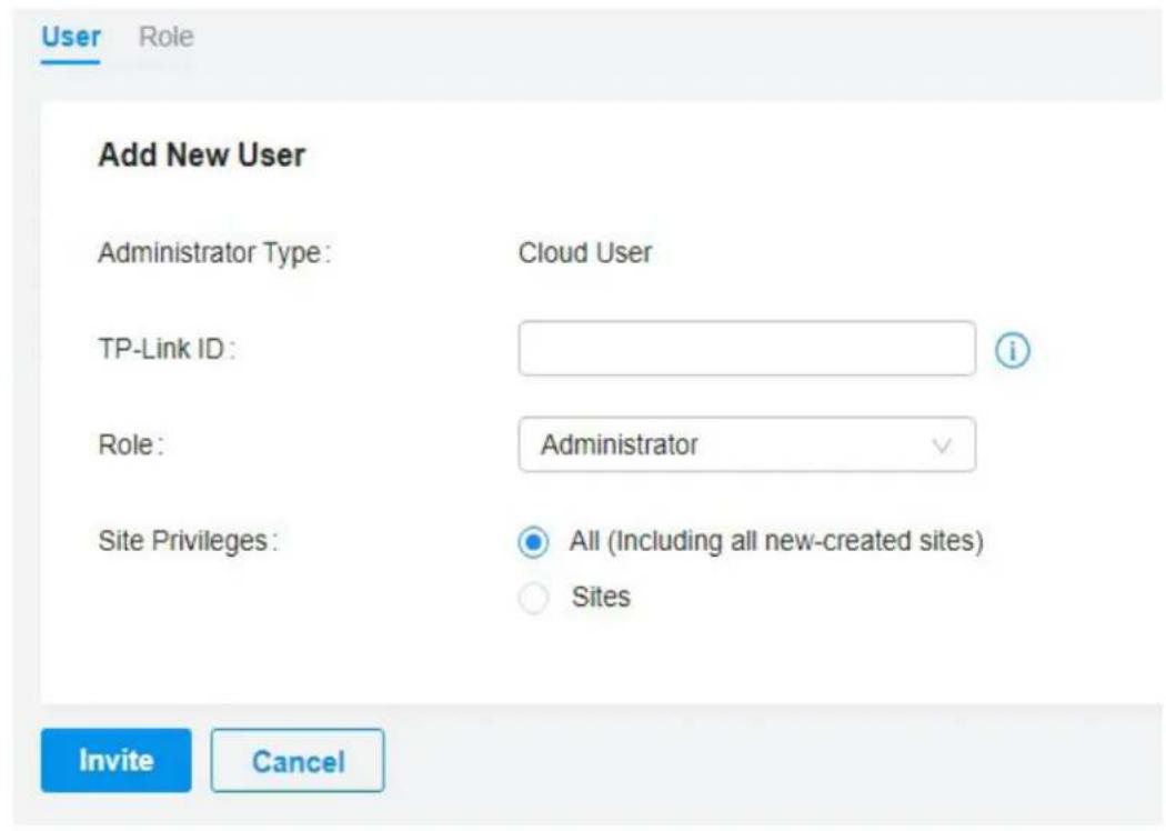
TP-Link ID
Enter an email address of the created cloud user, and then an invitation email will be sent to the email address.
If the email address has already been registered as a TP-Link ID, it will become a valid cloud user after accepting the invitation.
If the email address has not been registered, it will receive an invitation email for registration. After finishing registration, it will automatically becomes a valid cloud user.
Role Select a role for the created cloud user.
Administrator: This role has permissions to adopt and/or manage devices of the sites chosen in the site privileges, edit itself, create/edit/delete viewer accounts in its privileged sites. However, it cannot delete itself or edit/delete main administrator and other administrator accounts.
Viewer: This role can view the information of the sites chosen in the site privileges. It can only edit itself.
Site Privileges Assign the site permission to the created cloud user.
All: The created user has permission in all sites, including all new-created sites.
Sites: The created user has permission in the sites that are selected. Select the sites by checking the box before them.
Manage and Configure Sites
Start managing your network by creating and configuring sites so that you can configure and monitor your devices centrally while keeping things organized. The chapter includes the following sections:
• 1 Create Sites
• 2 Configure Site Settings

1 Create Sites
Overview
Different sites are logically separated network locations, like different subsidiary companies or departments. It is best practice to create one site for each LAN (Local Area Network) and add all the devices within the network to the site, including the gateway, switches and APs.
flowchart
graph TD
    subgraph Site A
        A1["Site A"] -->|Gateway| A2["AP"]
        A2 -->|Switch| A3["AP"]
        A3 --> B1["Site B"]
        A3 --> B2["AP"]
        A2 --> C1["Site C"]
        C1 -->|Gateway| C2["AP"]
        C2 -->|Switch| C3["AP"]
    end

    subgraph Site B
        B1 -->|Gateway| B2
        B2 -->|Switch| B3["AP"]
        B3 --> C4["Site D"]
        C4 -->|Gateway| C5["AP"]
        C5 -->|Switches| C6["AP"]
        C6 --> D5["Site E"]
    end

    subgraph Site C
        C1 -->|Gateway| C2
        C2 -->|Switch| C3
    end

    subgraph Site D
        D1["Site D"] -->|Gateway| D2["AP"]
        D2 -->|Switch| D3["AP"]
        D3 --> E1["Site E"]
    end

    style Site A fill:#f9f,stroke:#333
    style Site B fill:#f9f,stroke:#333
    style Site C fill:#f9f,stroke:#333
    style Site D fill:#f9f,stroke:#333
    style Site E fill:#f9f,stroke:#333
Devices at one site need unified configurations, whereas those at different sites are not relative. To make the best of a site, configure features simultaneously for multiple devices at the site, such as VLAN for switches, and SSID and WLAN Schedule for APs, rather than set them up one by one.
Configuration
To create and manage a site, follow these steps:
1) Create a site.
2) View and edit the site.
3) Go into the site.
Create a Site View and Edit the Site Go Into the Site
To create a site, choose one from the following methods according to your needs.
■ Create a site from scratch
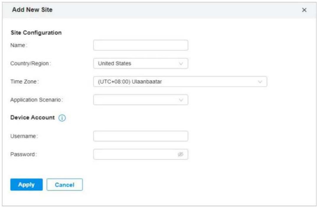
- In Global View, click +Add New Site in the Site List section.
- Enter a Site Name to identify the site, and configure other parameters according to where the site is located. Create a username and password for login to newly adopted devices. Then click Apply. The new site will be added to the Site List and the drop-down list of Organization.
■ Copy an existing site
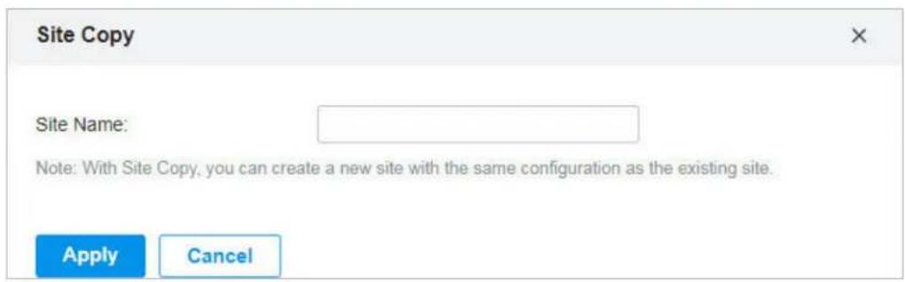
You can quickly create a site based on an existing one by copying its site configuration, wired configuration, and wireless configuration among others. After that, you can flexibly modify the new site configuration to make it different from the old.
- In the Site List, click 📋 in the ACTION column of the site which you want to copy.
- Enter a Site Name to identify the new site. Click Apply. The new site will be added to the Site List and the drop-down list of Organization.
Create a Site View and Edit the Site Go into the Site
After you create the site, you can view the site status in the Site List. You can click the icons in the ACTION column to edit, copy, delete and launch the site.

Create a Site View and Edit the Site Go Into the Site
To monitor and configure a site, you need first go into the site.
Click the 📋 icon of the site in the Site List to go into the site. Alternatively, select the site from the dropdown list of Organization.
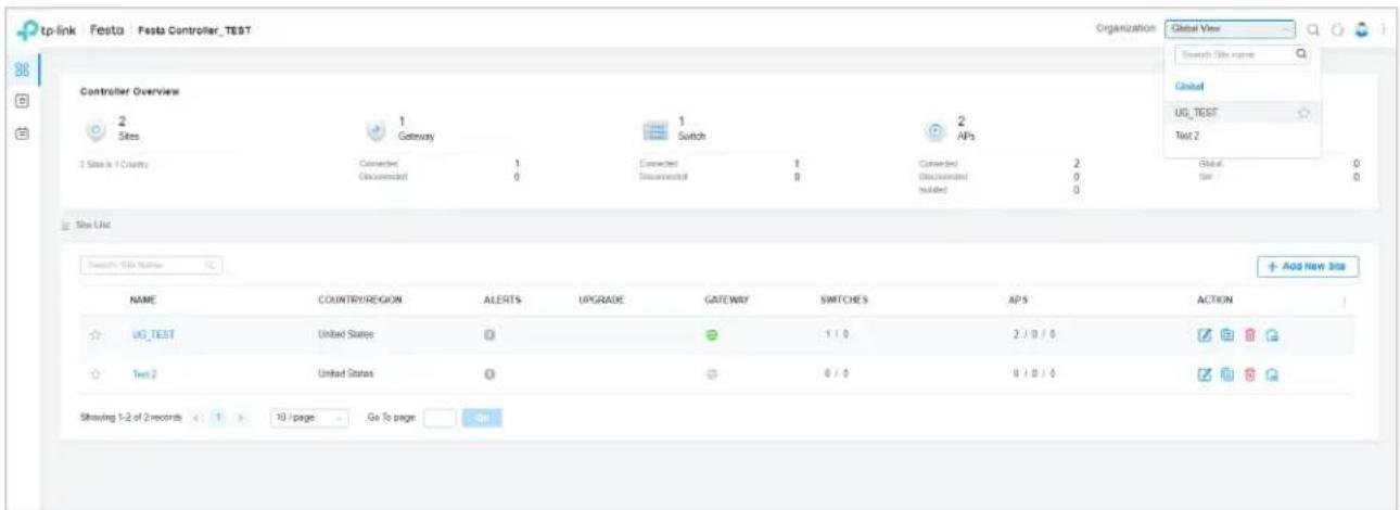
The Organization field indicates the site which you are currently in. Some configuration items in the menu are applied to the site which you are currently in, whereas others are applied to the whole controller.
2 Configure Site Settings
You can view and modify the configurations of the current site in Site Settings, including the basic site information, centrally-managed device features, and the device account. The features and device account configured here are applied to all devices on the site, so you can easily manage the devices centrally.
2.1 Site Configuration
Overview
In Site Configuration, you can view and modify the site name, location, time zone, and application scenario of the current site.
Configuration
Select a site from the drop-down list of Organization in the top-right corner, go to Settings > Site, and configure the following information of the site in Site Configuration. Click Save.
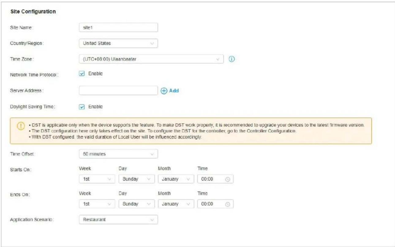
Site Name Specify the name of the current site. It should be no more than 64 characters.
Country/Region Select the location of the site.
Time Zone Select the time zone of the site.
| Network Time Protocol | With Network Time Protocol (NTP) enabled, the NTP server will assign network time to the site. Enter the IP address(es) of the NTP (Network Time Protocol) server. |
| Daylight Saving Time | Enable the feature if your country/region implements DST. When it is enabled, the iconDSTwill appear on the upper right, showing the DST settings and status. |
| Time Offset Select the time added in minutes when Daylight Saving Time starts. | |
| Starts On | Specify the time when the DST starts. The clock will be set forward by the time offset you specify. |
| Ends On | Specify the time when the DST ends.The clock will be set back by the time offset you specify. |
| Application Scenario | Specify the application scenario of the site. To customize your scenario, clickCreate New Groupin the drop-down list. |
2.2 Services
Overview
In Services, you can view and modify the features applied to devices on the current site. Some features are applied to all devices, such as LED, while some are applied to APs only, such as Channel Limit and Mesh.
Configuration
Select a site from the drop-down list of Sites in the top-right corner, go to Settings > Site, and configure the following features for the current site in Services. Click Save.
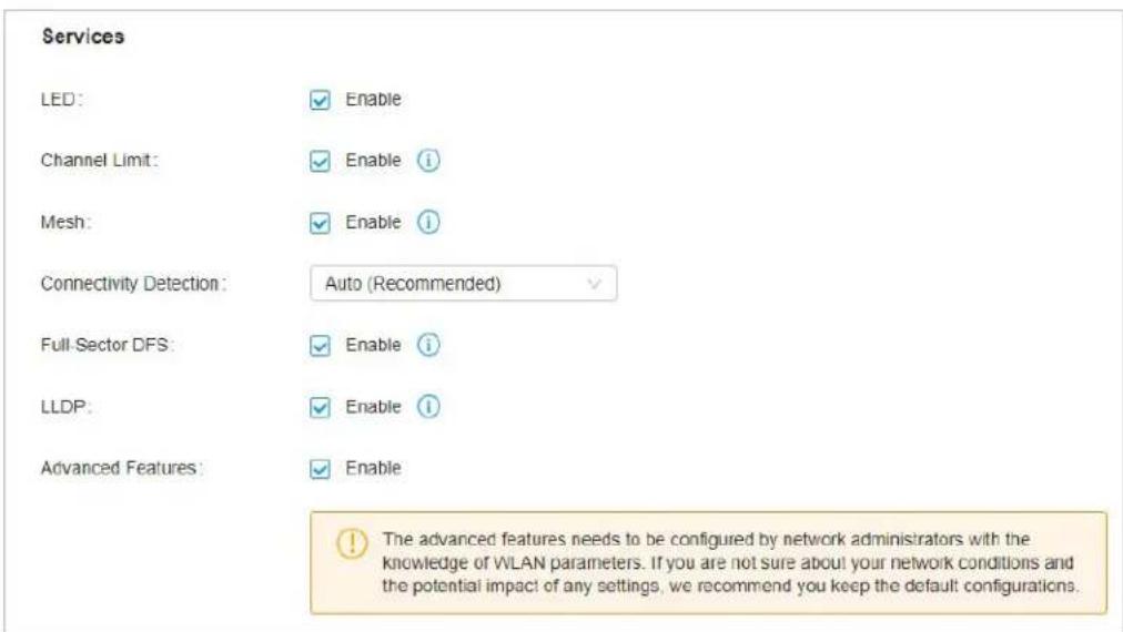
| LED Enable or disable LEDs of all devices in the site. | |
| By default, the device follows the LED setting of the site it belongs to. To change the LED setting for certain devices, refer to Manage, Configure, and Monitor Devices. | |
| Channel Limit | (For Outdoor APs) When enabled, outdoor APs do not use the channel with the frequency ranging from 5150 MHz to 5350 MHz to meet the local laws and regulations limit in EU countries. |
| Mesh When enabled, APs supporting Mesh can establish the mesh network at the site. | |
| Connectivity Detection | (For APs in the mesh network) Specify the method of Connection Detection when mesh is enabled.In a mesh network, the APs can send ARP request packets to a fixed IP address to test the connectivity. If the link fails, the status of these APs will change to Isolated.Auto (Recommended): Select this method and the mesh APs will send ARP request packets to the default gateway for the detection.Custom IP Address: Select this method and specify a desired IP address. The mesh APs will send ARP request packets to the custom IP address to test the connectivity. If the IP address of the AP is in different network segments from the custom IP address, the AP will use the default gateway IP address for the detection. |
| Full-Sector DFS | (For APs in the mesh network) With this feature enabled, when radar signals are detected on current channel by one AP, the other APs in the mesh network will be also informed. Then all APs in the mesh network will switch to an alternate channel.To enable this feature, enable Mesh first. |
| LLDP | Click the checkbox to enable LLDP (Link Layer Discovery Protocol) for device discovery and auto-configuration of VoIP devices. |
| Advanced Features | (For APs) When enabled, you can configure more features for APs in Advanced Features.When disabled, these features keep the default settings.For detailed configuration, refer to Advanced Features. |
2.3 Advanced Features
Overview
Advanced features include Fast Roaming, Band Steering, and Beacon Control. They are applicable to APs only. With these advanced features configured properly, you can improve the network's stability, reliability and communication efficiency.
Advanced features are recommended to be configured by network administrators with the WLAN knowledge. If you are not sure about your network conditions and the potential impact of all settings, keep Advanced Features disabled in Services to use their default configurations.
Configuration
Select a site from the drop-down list of Organization in the top-right corner, go to Settings > Site, and enable Advanced Features in Services first. Then configure the following features in Advanced Features. Click Save.
Advanced Features
Fast Roaming:

Enable

Dual Band 11k Report:

Enable

Force-Disassociation:

Enable

Band Steering:
Disable


Beacon Control
2.4 GHz
5 GHz
Beacon Interval:
100
ms
(40-100)
DTIM Period:
1
(1-255)
RTS Threshold:
2347
(1-2347)
Fragmentation Threshold:
2346
(256-2346, works only on 802.11b/g mode.)
Airtime Fairness:

Enable

| Fast Roaming | With this feature enabled, wireless clients that support 802.11k/v can improve fast roaming experience when moving among different APs.By default, it is disabled. This feature is available for some certain devices. |
| Dual Band 11k Report | When disabled, the controller provides neighbor list that contains only neighbor APs in the same band with which the client is associated.When enabled, the controller provides neighbor list that contains neighbor APs in both 2.4 GHz and 5 GHz bands.This feature is available only when Fast Roaming is enabled. By default, it is disabled. |
| Force-Disassociation | With this feature disabled, the AP only issues an 802.11v roaming suggestion when a client's link quality drops below the predefined threshold and there is a better option of AP, but whether to roam or not is determined by the client.With this feature enabled, the AP will force disassociate the client if it does not re-associate to another AP.This feature is available only when Fast Roaming is enabled. By default, it is disabled. |
| Band Steering | Band steering can adjust the number of clients in 2.4 GHz and 5 GHz bands to provide better wireless experience.When enabled, multi-band clients will be steered to the 5 GHz band according to the configured parameters. This function can improve the network performance because the 5 GHz band supports a larger number of non-overlapping channels and is less noisy. |
| Beacon Control | Beacons are transmitted periodically by the AP to announce the presence of a wireless network for the clients. Click ☐, select the band, and configure the following parameters of Beacon Control.Beacon Interval: Specify how often the APs send a beacon to clients. By default, it is 100.DTIM Period: Specify how often the clients check for buffered data that are still on the AP awaiting pickup. By default, the clients check for them at every beacon.DTIM (Delivery Traffic Indication Message) is contained in some Beacon frames indicating whether the AP has buffered data for client devices. An excessive DTIM interval may reduce the performance of multicast applications, so we recommend that you keep the default interval, 1.RTS Threshold: RTS (Request to Send) can ensure efficient data transmission by avoiding the conflict of packets. If a client wants to send a packet larger than the threshold, the RTS mechanism will be activated to delay packets of other clients in the same wireless network.We recommend that you keep the default threshold, which is 2347. If you specify a low threshold value, the RTS mechanism may be activated more frequently to recover the network from possible interference or collisions. However, it also consumes more bandwidth and reduces the throughput of the packet.Fragmentation Threshold: Fragmentation can limit the size of packets transmitted over the network. If a packet to be sent exceeds the Fragmentation threshold, the Fragmentation function will be activated, and the packet will be fragmented into several packets. By default, the threshold is 2346.Fragmentation helps improve network performance if properly configured. However, too low fragmentation threshold may result in poor wireless performance because of the increased message traffic and the extra work of dividing up and reassembling frames.Airtime Fairness: With this option enabled, each client connecting to the AP can get the same amount of time to transmit data so that low-data-rate clients do not occupy too much network bandwidth and network performance improves as a whole. We recommend you enable this function under multi-rate wireless networks. |
2.4 Device Account
You can specify a device account for all adopted devices on the site in batches. Once the devices are adopted by the Controller, their username and password become the same as settings in Device Account to protect the communication between the controller and devices. By default, the username is admin and the password is generated randomly.
Select a site from the drop-down list of Organization. Go to Settings > Site and modify the username and password in Device Account. Click Save and the new username and password are applied to all devices on the site.
Device Account
Username:
admin
Password:
●●●●●●●

Manage, Configure, and Monitor Devices
This chapter guides you on how to manage, configure and monitor controller-managed devices, including gateways, switches and APs. You can configure the devices individually or in batches to modify the configurations of certain devices. The chapter includes the following sections:
• 1 Adopt Devices
• 2 Introduction to the Devices Page
• 3 Configure and Monitor the Gateway
• 4 Configure and Monitor Switches
• 5 Configure and Monitor APs
1 Adopt Devices
Overview
After you create a site, add your devices to the site by making the controller adopt them. Make sure that your devices in each LAN are added to the corresponding site so that they can be managed centrally.
flowchart
graph TD
    subgraph Site A
        A1["Site A"] -->|Gateway| A2["AP"]
        A2 -->|Switch| A3["AP"]
        A3 -->|AP| B1["AP"]
        A4["Site B"] -->|Gateway| A5["AP"]
        A5 -->|Switch| A6["AP"]
        A6 -->|AP| B2["AP"]
        A7["Site C"] -->|Gateway| A8["AP"]
        A8 -->|Switch| A9["AP"]
    end

    subgraph Site D
        D1["Site D"] -->|Gateway| D2["AP"]
        D2 -->|Switch| D3["AP"]
        D3 -->|AP| E1["AP"]
        D4["Site E"] -->|Gateway| D5["AP"]
        D5 -->|Switch| D6["AP"]
        D6 -->|AP| E7["AP"]
    end

    Site A -->|Gateway| SiteB
    SiteA -->|Gateway| SiteC
    SiteD -->|Gateway| SiteE
    SiteB -->|Gateway| SiteA
    SiteC -->|Gateway| SiteB
    SiteD -->|Gateway| SiteC
    SiteE -->|Gateway| SiteA
    style SiteA fill:#f9f,stroke:#333
    style SiteB fill:#bbf,stroke:#333
    style SiteC fill:#bfb,stroke:#333
    style SiteD fill:#fbf,stroke:#333
    style SiteE fill:#fbf,stroke:#333
Configuration
To adopt the devices on the Controller, follow these steps:
1) Connect to the internet.
2) Adopt the devices.
Adopt the Devices
1. Set up the network.
Make sure that your devices are connected to the internet.
Festa Cloud-Based Controller
Unified
Management from
One Interface
Gateway
Switch
APs
Gateway A
Switch
AP AP
LAN 1
If you are using firewalls in your network, make sure that the firewall does not block traffic from the Controller. To configure your firewall policy, you may want to know the URL of the Controller. After you open the web page of the Controller, you can get the URL from the address bar of the browser.
2. (Optional) Test the network.
If you are not sure whether the devices are connected to the internet, it is recommended to do the ping test from the devices to a public IP address, such as 8.8.8.8.
If the ping result shows the packets are received, it implies that the devices are connected to the internet. Otherwise, the devices are not connected to the internet, and you need to check your network.
Connect to the Internet
On the controller configuration page, go into the site where you want to add the devices. Go to Devices and click +Add Devices. Use the S/N to add your devices to the Controller. Once the devices are adopted, they are subject to central management in the site.
2 Introduction to the Devices Page
Overview
The Devices page displays all TP-Link devices discovered by the Controller and their general information. For an easy monitoring of the devices, you can customize the column and filter the devices for a better overview of device information. Also, quick operations and Batch Edit are available for configurations.
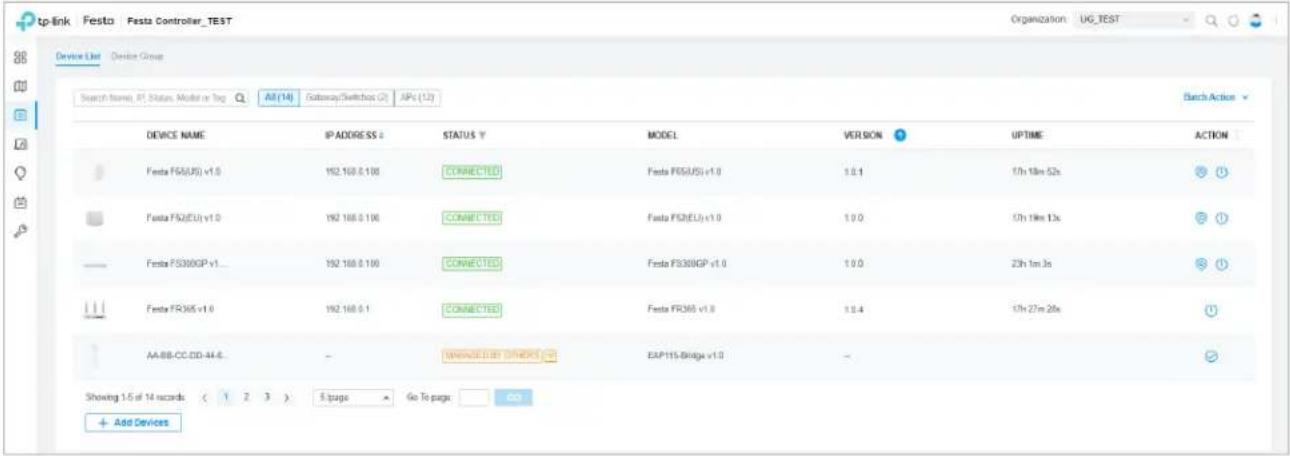
According to the connection status, the devices have the following status: PENDING, ISOLATED, CONNECTED, MANAGED BY OTHERS, HEARTBEAT MISSED, and DISCONNECTED. The icons in the Status column are explained as follows:
| PENDING | The device is in Standalone Mode or with factory settings, and has not been adopted by the Controller. To adopt the device, click and the Controller will use the default username and password to adopt it. When adopting, its status will change from ADOPTING, PROVISIONING, CONFIGURING, to CONNECTED eventually. |
| ISOLATED | (For APs in the mesh network) The AP once managed by the Controller via a wireless connection now cannot reach the gateway. You can rebuild the mesh network by connecting it to an AP in the CONNECTED status, then the isolated AP will turn into a connected one. For detailed configuration, refer toMesh. |
| CONNECTED | The device has been adopted by the Controller and you can manage it centrally. A connected device will turn into a pending one after you forget it. |
| MANAGED BY OTHERS | The device has already been managed by another Controller. You can reset the device or provide the username and password to unbind it from another controller and adopt it in the current Controller. |
| HEARTBEAT MISSED | A transition status between CONNECTED and DISCONNECTED.Once connected to the Controller, the device will send inform packets to the Controller in a regular interval to maintain the connection. If the Controller does not receive its inform packets in 30 seconds, the device will turn into the HEARTBEAT MISSED status. For a heartbeat-missed device, if the Controller receives an inform packet from the device in 5 minutes, its status will become CONNECTED again; otherwise, its status will become DISCONNECTED. |
| DISCONNECTED | The connected device has lost connection with the Controller for more than 5 minutes. |

(For APs in the mesh network) When this icon appears with a status icon, it indicates the AP with mesh function and no wired connection is detected by the Controller. You can connect it to an uplink AP through Mesh.
Configuration
■ Customize the Column
To customize the columns, click next to Action and check the boxes of information type.
To change the list order, click the column head and will appear to indicate the ascending or descending order.
![tp-link Festa Festa Controller_78ST Device List Citing Group Search Right: IP Status, Model or Tag All [16] Gateway/Switches (2) APIs (12) Bench Action DEVICE NAME STATUS MODEL VERSION UPTIME DOWN UP ACTION Festa F530BOP v1... CONNECTED Festa F530BOP v1.0 1.0.0 23h 6m 8s 12.46 MB 8.41 MB Festa FRO85 v1.0 CONNECTED Festa FRO85 v1.0 1.0.4 17h 32m 25s 44.90 MB 22.25 MB Festa F65(US) v1.0 CONNECTED Festa F65(US) v1.0 1.0.1 17h 24m 25s 0 Bytes 0 Bytes Festa F65(EU) v1.0 CONNECTED Festa F65(EU) v1.0 1.0.0 17h 24m 15s 0 Bytes 0 Bytes](/content/2026/05/905251/images/8a92f1a9fd1ce819b26234afe73b328c5345056b9271fd885e26b7fcdd69b0b2.jpg)
■ Filter the Devices
Use the search box and tab bar above the table to filter the devices.
To search the devices, enter the text in the search box or select a tag from the drop-down list. As for the device tag, refer to the general configuration of switches and APs.
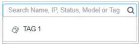
To filter the devices, a tab bar is above the table to filter the devices by device type. You can also filter the devices by their status by clicking in the Status column. If you select the APs tab, another tab bar will be available to change the column quickly.
| Overview | Displays the device name, IP address, status, model, firmware version, uptime, clients, download traffic, upload traffic, and channel by default. |
| Mesh | Displays the information of devices in the mesh network, including the device name, IP address, status, model, uplink device, channel, and the number of downlink devices, clients and hops by default. |
| Performance | Displays the device name, IP address, status, uptime, channel, the number of 2.4 GHz and 5 GHz clients, Rx rate, and Tx rate by default. |
| Config | Displays the device name, status, version, WLAN group, and the radio settings for 2.4 GHz and 5 GHz by default. |
■ Quick Operations
Click the icons in Header or the Action column to quickly adopt, locate, upgrade, or reboot the device.
| Start Rolling Upgrade | Click to upgrade the managed devices in batches. |
| Click to check if there is new firmware for the managed devices. | |
| (For pending devices) Click to adopt the device. | |
| (For connected switches and APs) Click this icon and the LEDs of the device will flash to indicate the device's location. The LEDs will keep flashing for 10 minutes, or you can click theicon to stop the flashing. | |
| (For connected devices) Click to reboot the device. | |
| Click to upgrade the device's firmware version. This icon appears when the device has a new firmware version. |
■ Batch Edit (for Switches and APs)
After selecting the Gateway/Switches or APs tab, you can adopt or configure the switches or APs in batches. Batch Config is available only for the devices in CONNECTED/DISCONNECTED/HEARTBEAT MISSED/ISOLATED status, while Batch Adopt is available for the devices in the PENDING/MANAGED BY OTHERS status.
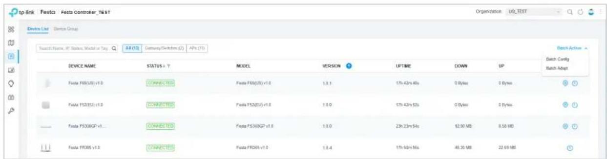
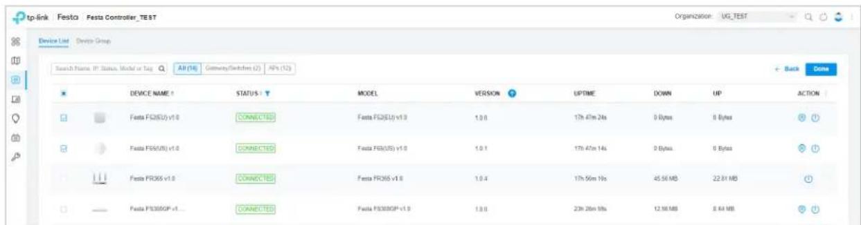
Click Batch Action. select Batch Adopt, click the checkboxes of devices, and click Done. If the selected devices are all in the PENDING status, the Controller will adopt then with the default username and password. If not, enter the username and password manually to adopt the devices.

Click Batch Action, select Batch Config, click the checkboxes of devices, and click Done. Then the Properties window appears. There are two tabs in the window: Devices and Config.
In Devices, you can click to remove the device from the current batch configuration.
In Config, all settings are Keep Existing by default. For detailed configurations, reference configuration of switches and APs.
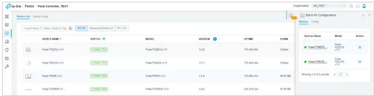
| Click to minimize the Properties window to an icon. To reopen the minimized Properties window, click ☐. | |
| Click to maximize the Properties window. You can also use the icon on pages other than the Devices page. | |
| Click to close the Properties window of the chosen device(s). Note that the unsaved configuration will be lost. | |
| The number on the lower-right shows the number of devices in the batch configuration. |
3 Configure and Monitor the Gateway
In the Properties window, you can configure the gateway managed by the Controller and monitor its performance. By default, all configurations are synchronized with the current site.
To open the Properties window, click the entry of the gateway. A monitor panel and several tabs are listed in the Properties window. Most features to be configured are gathered in the Config tab, such as IP, SNMP, and Hardware Offload, while other tabs are mainly used to monitor the devices.
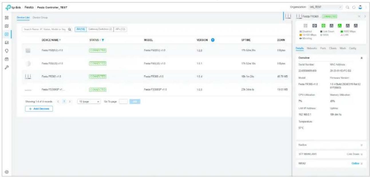
① Note:
- You can adopt only one gateway in one site.
- The available functions in the window vary due to the model and status of the device.
3.1 Configure the Gateway
In the Properties window, you can view and configure the ports in Ports, and configure the gateway features in Config.
Ports
In Ports, you can view the status and edit settings of the ports.
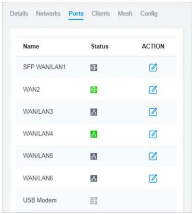
To configure a port, click in the table.
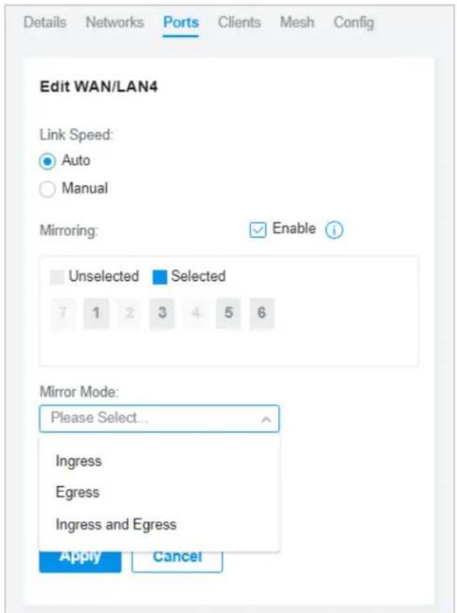
Link Speed Select the speed mode for the port.
Auto: The port negotiates the speed and duplex automatically.
Manual: Specify the speed and duplex from the drop-down list manually.
Mirroring Mirroring is used to analyze network traffic and troubleshoot network problems.
Enable this option to set the edited port as the mirroring port, then specify one or multiple mirrored ports. The gateway will send a copy of traffics passing through the mirrored ports to the mirroring port.
Mirror Mode Specify the directions of the traffic to be mirrored.
Ingress and Egress: Both the incoming and outgoing packets through the mirrored port will be copied to the mirroring port.
Ingress: The packets received by the mirrored port will be copied to the mirroring port.
Egress: The packets sent by the mirrored port will be copied to the mirroring port.
Config
In the Properties window, click Config and then click the sections to configure the features applied to the gateway.
■ General
In General, you can specify general settings of the gateway.
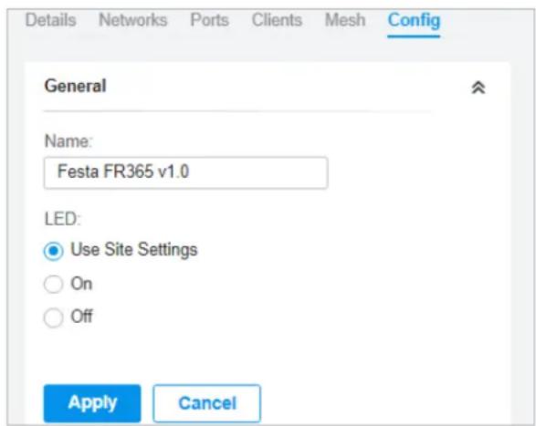
Name Specify a name of the device.
LED
Select the way that device's LEDs work.
Use Site Settings: The device's LED will work following the settings of the site. To view and modify the site settings, refer to Services.
On/Off: The device's LED will keep on/off.
■ Radios (for wireless gateways only)
In Radios, you can control how and what type of radio signals the gateway emits. Select each frequency band and configure the parameters. Different models support different bands.
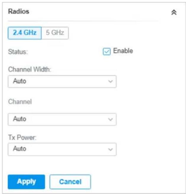
| Status If you disable the frequency band, the radio on it will turn off. | |
| Channel Width | Specify the channel width of the band. Different bands have different available options. We recommend using the default value. |
| Channel | Specify the operation channel of the gateway to improve wireless performance. If you selectAutofor the channel setting, the gateway scans available channels and selects the channel where the least amount of traffic is detected. |
| Tx Power | Specify the Tx Power (Transmit Power) in the 4 options: Low, Medium, High and Custom. The actual power of Low, Medium and High are based on the minimum transmit power (Min. Txpower) and maximum transmit power (Max. TxPower), which may vary in different countries and regions.Low: Min. TxPower + (Max. TxPower-Min. TxPower) * 20% (round off the value)Medium: Min. TxPower + (Max. TxPower-Min. TxPower) * 60% (round off the value)High: Max. TxPowerCustom: Specify the value manually. |
■ WLANs
In WLANs, you can apply the WLAN group to the gateway and specify a different SSID name and password to override the SSID in the WLAN group. After that, clients can only see the new SSID and
use the new password to access the network. To create or edit WLAN groups, refer to Configure Wireless Networks.
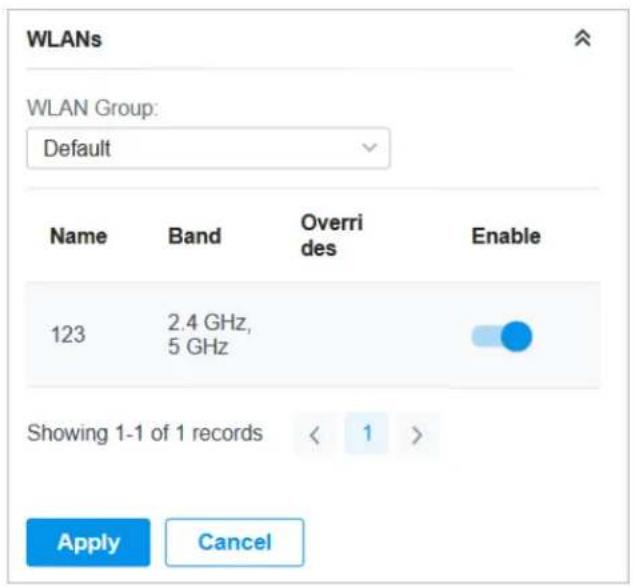
(Only for configuring a single device) To override the SSID, select a WLAN group, click in the entry and then the following page appears.
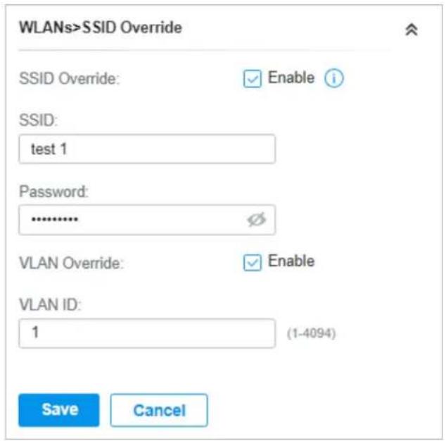
| SSID Override | Enable or disable SSID Override on the gateway. After enabling SSID Override, specify the new SSID and password to override the current one.Note: If the SSID is enabled with 11os PPSK, the override function will make the SSID unavailable. |
| VLAN Override | Enable or disable VLAN Override. After enabling VLAN Override, enter a VLAN ID to assign the new SSID to the VLAN. |
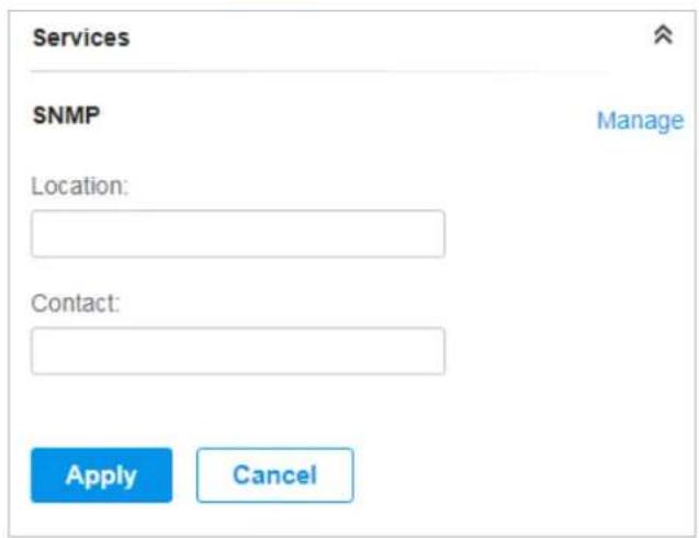
■ Services
In Services, you can configure SNMP to write down the location and contact detail. You can also click Manage to jump to Settings > Services > SNMP, and for detailed configuration of SNMP service, refer to SNMP.
■ Advanced
In Advanced, you can configure advanced settings to make better use of network resources.
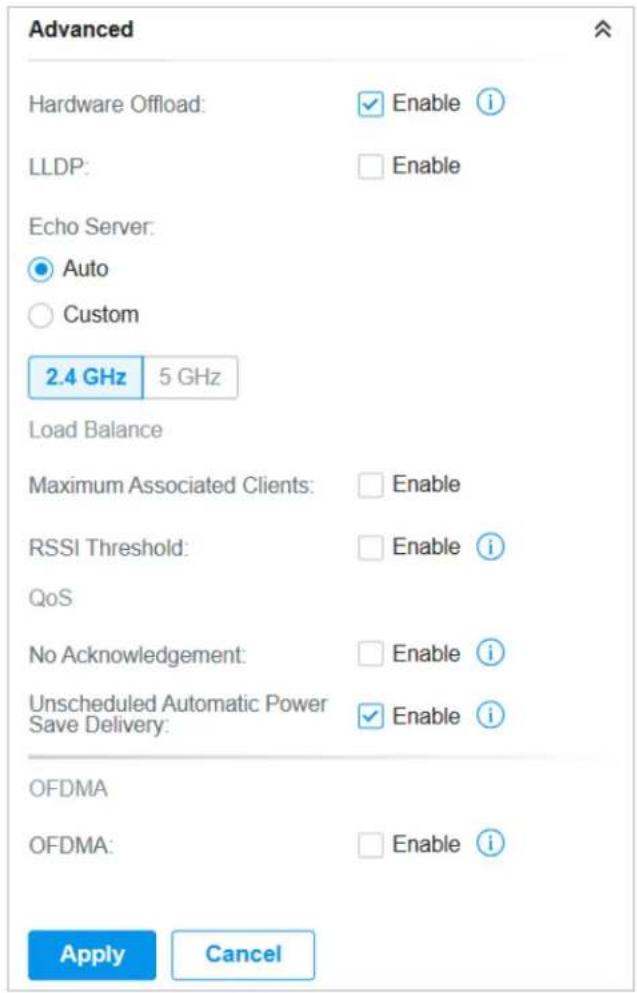
| Hardware Offload | Hardware Offload can improve performance and reduce CPU utilization by using the hardware to offload packet processing.Note that this feature cannot take effect if QoS, Bandwidth Control, or Session Limit is enabled. To configure Bandwidth Control and Session Limit for the gateway, refer toTransmission. |
| LLDP LLDP (Link Layer Discovery Protocol) can help discover devices. | |
| Echo Server | Echo Server is used to test the connectivity and monitor the latency of the network automatically or manually. If you clickCustom, enter the IP address or hostname of your custom server. |
| Maximum Associated Clients | Enable this function and specify the maximum number of connected clients. If the connected client reaches the maximum number, the gateway will disconnect those with weaker signals to make room for other clients requesting connections. |
| RSSI Threshold | Enable this function and enter the threshold of RSSI (Received Signal Strength Indication). If the client's signal strength is weaker than the threshold, the client will lose connection with the gateway. |
| No Acknowledgement | Enable this function to specify that the gateway will not acknowledge frames with QoS No Ack. Enabling No Acknowledgment can bring more efficient throughput, but it may increase error rates in a noisy Radio Frequency (RF) environment. |
| Unscheduled Automatic Power Save Delivery | When enabled, this function can greatly improve the energy-saving capacity of clients. |
| OFDMA | (Only for models supporting 802.11 ax) Enable this feature to enable multiple users to transmit data simultaneously, and it will greatly improves speed and efficiency. Note that the benefits of OFDMA can be fully enjoyed only when the clients support OFDMA. |
■ Manage Device
In Manage Device, you can upgrade the device's firmware version manually, move it to another site, synchronize the configurations with the controller, and forget the gateway.
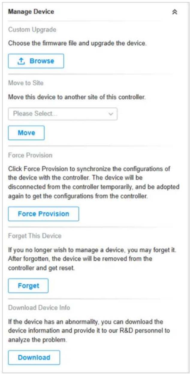
| Custom Upgrade | Click Browse and choose a file from your computer to upgrade the device. When upgrading, the device will be rebooted and readopted by the controller. You can also check the box of Upgrade all devices of the same model in the site after the firmware file is uploaded. |
| Move to Site | Select a site which the device will be moved to. After moving to another site, device configurations on the prior site will be replaced by that on the new site, and its traffic history will be cleared. |
| Force Provision | Click Force Provision to synchronize the configurations of the device with the controller. The device will lose connection temporarily, and be adopted to the controller again to get the configurations from the controller. |
| Forget This Device | Click Forget and then the device will be removed from the controller. Once forgotten, all configurations and history related to the device will be wiped out. |
| Download Device Info | If the device has an abnormality, you can download the device information and provide it to our R&D personnel to analyze the problem.⚠️ Note:Firmware updates are required for earlier devices to obtain complete information. |
■ Common Settings
In Common Settings, you can click the path to jump to corresponding modules quickly.
| Common Settings |
| Settings->Wired Networks->Internet |
| To configure the network of the WAN port, go to the Settings->Wired Networks->Internet page. |
| Settings->Wired Networks->LAN |
| To view and configure the settings of the network interfaces, go to the Settings->Wired Networks->LAN page. |
| Settings->VPN |
| To view and configure the VPN network, go to the Settings->VPN page. |
| Settings->Network Security |
| To view and configure the ACL rules for the network, go to the Settings->Network Security page. |
| Settings->Services |
| To view and configure the network services, go to the Settings->Services page. |
3.2 Monitor the Gateway
One panel and four tabs are provided to monitor the device in the Properties window: Monitor Panel, Details, Networks, Clients, and Mesh.
Monitor Panel
The monitor panel displays the gateway's ports, and it uses colors and icons to indicate different connection status and port types. When the gateway is pending or disconnected, all ports are disabled.
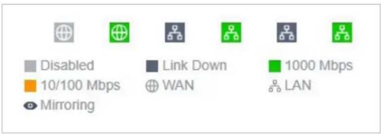
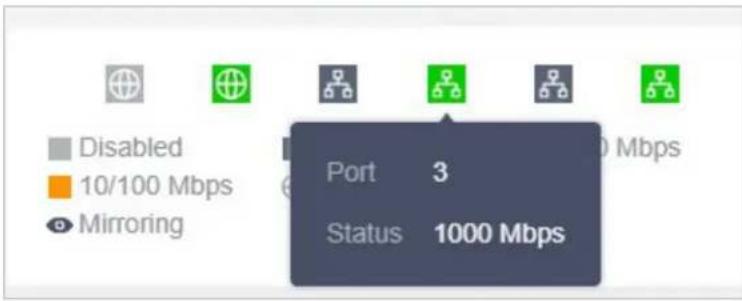
You can hover the cursor over the port icon for more details.
Details
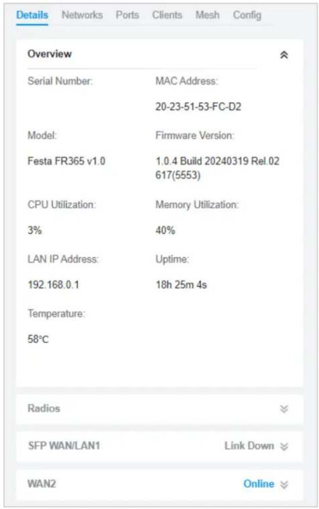
In Details, you can view the basic information of the gateway and the statistics of WAN ports to know the device's running status briefly. The listed information varies with devices.
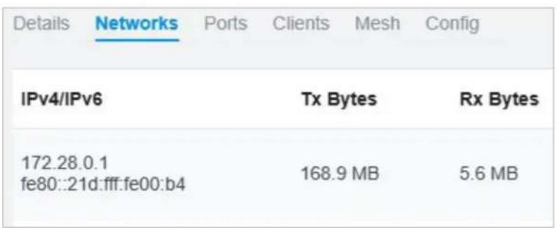
Networks
In Networks, you can view the network information of the gateway.
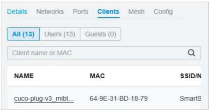
Clients
In Clients, you can view the wireless clients of the gateway.
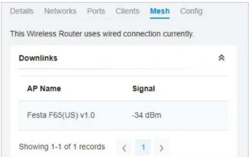
Mesh (For wireless gateway only)
In Mesh, you can view the mesh downlinks of the gateway.
4 Configure and Monitor Switches
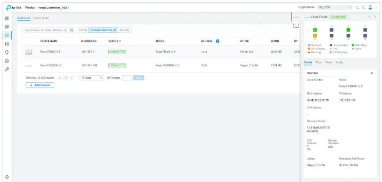
In the Properties window, you can configure one or some switches connected to the Controller and monitor the performance. Configurations changed in the Properties window will be applied only to the selected switch(es). By default, all configurations are synchronized with the current site.
To open the Properties window, click the entry of a switch, or click Batch Action, and then Batch Config to select switches for batch configuration. A monitor panel and several tabs are listed in the Properties window. Most features to be configured are gathered in the Ports and Config tab, such as the port mirroring, IP address, and Management VLAN, while other tabs are mainly used to monitor the devices.

Note:
- The available functions in the window vary due to the model and status of the device.
• In Batch Config, you can only configure the selected devices, and the unaltered configurations will keep the current settings.
4.1 Configure Switches
In the Properties window, you can view and configure the profiles applied to ports in Ports, and in Config, you can configure the switch features.
Ports
Port and LAG are two tabs designed for physical ports and LAGs (Link Aggregation Groups), respectively. Under the Port tag, all ports are listed but you can configure physical ports only, including overriding the applied profiles, configuring Port Mirroring, and specifying ports as LAGs. Under the LAG tag, all LAGs are listed and you can view and modify the configurations of existing LAGs.
Port
In Port, you can view and configure all ports' names and applied profiles.
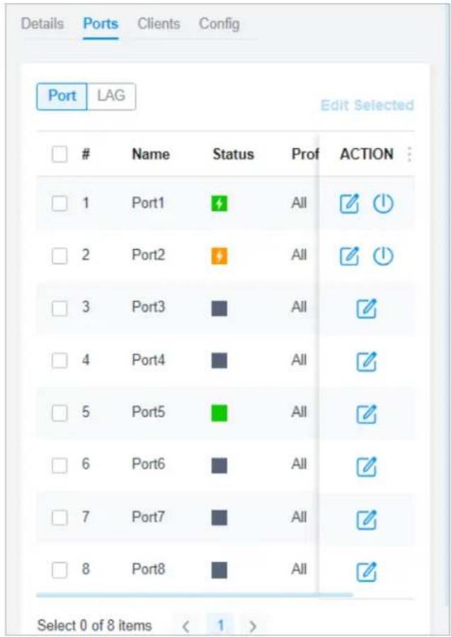
Status Displays the port status in different colors.
: The port profile is Disabled. To enable it, click to change the profile.
The port is enabled, but no device or client is connected to it.
The port is running at 1000 Mbps.
: The port is running at 10/100 Mbps.
Profile Displays the profile applied to the port.
Action
☑: Click to edit the port name and configure the profile applied to the port.
(For PoE ports) Click to reboot the connected powered devices (PDs).
To configure a single port, click In the table. To configure ports in batches, click the checkboxes and then click Edit Selected. Then you can configure the port name and profile. By default, all settings are Keep Existing for batch configuration.
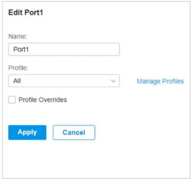
| Name Enter the port name. | |
| Profile | Select the profile applied to the port from the drop-down list. Click Manage Profiles to jump to view and manage profiles. For details, refer to Configure Wired Networks. |
| Profile Overrides | Click the checkbox to override the applied profile. The parameters to be configured vary in Operation modes, |
With Profile Overrides enabled, select an operation mode and configure the following parameters to override the applied profile, configure a mirroring port, or configure a LAG.
- Override the Applied Profile
If you select Switching for Operation, configure the following parameters and click Apply to override the applied profile. To discard the modifications, click Remove Overrides and all profile configurations will become the same as the applied profile.
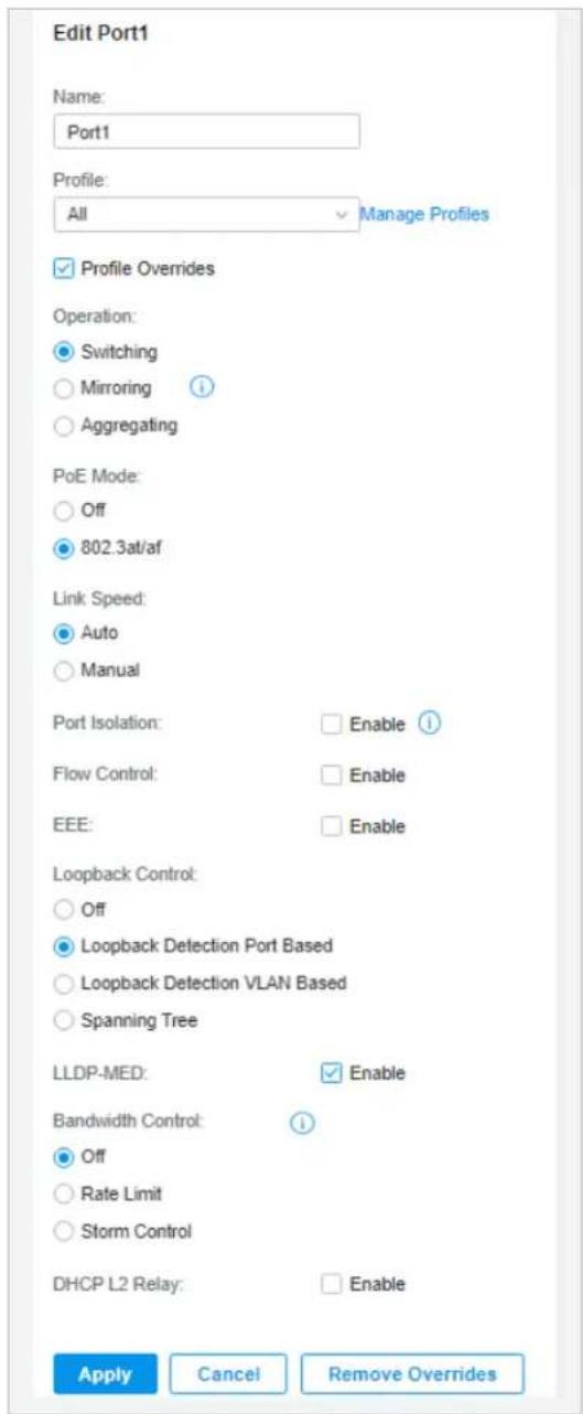
PoE Mode (Only for PoE ports) Select the PoE (Power over Ethernet) mode for the port.
Off: Disable PoE function on the PoE port.
802.3at/af: Enable PoE function on the PoE port.
| Link Speed Select the speed mode for the port. | |
| Auto: The port negotiates the speed and duplex automatically. | |
| Manual: Specify the speed and duplex from the drop-down list manually. | |
| Port Isolation | Click the checkbox to enable Port Isolation. An isolated port cannot communicate directly with any other isolated ports, while the isolated port can send and receive traffic to non-isolated ports. |
| Flow Control | With this option enabled, when a device gets overloaded it will send a PAUSE frame to notify the peer device to stop sending data for a specified period of time, thus avoiding the packet loss caused by congestion. |
| EEE Click the checkbox to enable EEE (Energy Efficient Ethernet) to allow power reduction. | |
| Loopback Control | Loopback refers to the routing of data streams back to their source in the network. You can disable loopback control for the network or choose a method to prevent loopback happening in your network.Off: Disable loopback control on the port.Loopback Detection Port Based: Loopback Detection Port Based helps detect loops that occur on a specific port. When a loop is detected on a port, the port will be blocked.Loopback Detection VLAN Based: Loopback Detection VLAN Based helps detect loops that occur on a specific VLAN. When a loop is detected on a VLAN, the VLAN will be blocked.Spanning Tree: Select STP (Spanning Tree Protocol) to prevent loops in the network. STP helps block specific ports of the switches to build a loop-free topology and detect topology changes and automatically generate a new loop-free topology. To make sure Spanning Tree takes effect on the port, go to the Config tab and enable Spanning Tree on the switch. |
| LLDP-MED Click the checkbox to enable LLDP-MED (Link Layer Discovery Protocol-Media Endpoint Discovery) for device discovery and auto-configuration of VoIP (Voice over Internet Protocol) devices. | |
| Bandwidth Control | Select the type of Bandwidth Control functions to control the traffic rate and specify traffic threshold on each port to make good use of network bandwidth.Off: Disable Bandwidth Control for the port.Rate Limit: Select Rate limit to limit the ingress/egress traffic rate on each port. With this function, the network bandwidth can be reasonably distributed and utilized.Storm Control: Select Storm Control to allow the switch to monitor broadcast frames, multicast frames and UL-frames (Unknown unicast frames) in the network. If the transmission rate of the frames exceeds the specified rate, the frames will be automatically discarded to avoid network broadcast storm. |
| Ingress Rate Limit | With Rate Limit selected, click the checkbox and specify the upper rate limit for receiving packets on the port. |
| Egress Rate Limit | When Rate Limit selected, click the checkbox and specify the upper rate limit for sending packets on the port. |
| Broadcast Threshold | With Storm Control selected, click the checkbox and specify the upper rate limit for receiving broadcast frames. The broadcast traffic exceeding the limit will be processed according to the Action configurations. |
| Multicast Threshold | With Storm Control selected, click the checkbox and specify the upper rate limit for receiving multicast frames. The multicast traffic exceeding the limit will be processed according to the Action configurations. |
| Unknown Unicast Threshold | With Storm Control selected, click the checkbox and specify the upper rate limit for receiving unknown unicast frames. The traffic exceeding the limit will be processed according to the Action configurations. |
| Action When Storm Control selected, select the action that the switch will take when the traffic exceeds its corresponding limit.Drop: With Drop selected, the port will drop the subsequent frames when the traffic exceeds the limit.Shutdown: With Shutdown selected, the port will be shutdown when the traffic exceeds the limit. | |
| Recover Time | With Shutdown selected as the Action, specify the recover time, and the port will be opened after the specified time. |
| DHCP L2 Relay Click the checkbox to enable DHCP L2 Relay for the network. | |
| Format Select the format of option 82 sub-option value field.Normal: The format of sub-option value field is TLV (type-length-value).Private: The format of sub-option value field is just value. | |
| Circuit ID | (Optional) Enter the customized circuit ID. The circuit ID configurations of the switch and the DHCP server should be compatible with each other. If it is not specified, the switch will use the default circuit ID when inserting Option 82 to DHCP packets. |
| Remote ID | (Optional) Enter the customized remote ID. The remote ID configurations of the switch and the DHCP server should be compatible with each other. If it is not specified, the switch will use its own MAC address as the remote ID. |
- Configure a Mirroring Port
If you select Mirroring as Operation, the edited port can be configured as a mirroring port. Specify other ports as the mirrored port, and the switch sends a copy of traffics passing through the mirrored port to the mirroring port. You can use mirroring to analyze network traffic and troubleshoot network problems.
To configure Mirroring, select the mirrored port or LAG, specify the following parameters, and click Apply. To discard the modifications, click Remove Overrides and all profile configurations become the same as the applied profile.
Note that the mirroring ports and the member ports of LAG cannot be selected as mirrored ports.
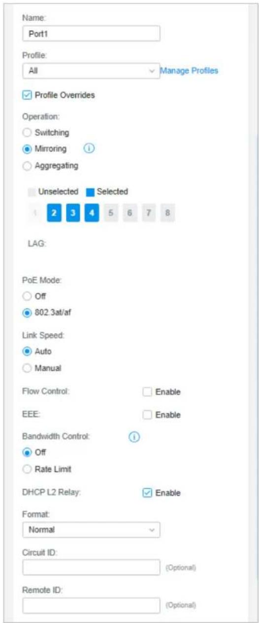
PoE Mode (Only for PoE ports) Select the PoE mode for the port.
Off: Disable PoE on the PoE port.
802.3at/af: Enable PoE on the PoE port.
Link Speed Select the speed mode for the port.
Auto: The port negotiates the speed and duplex automatically.
Manual: Specify the speed and duplex from the drop-down list manually.
| Bandwidth Control | Bandwidth control optimizes network performance by limiting the bandwidth of specific sources.Off: Disable bandwidth control on the port.Rate Limit: Enable bandwidth control on the port, and you need to specify the ingress and/or egress rate limit. |
| Ingress Rate Limit | With Rate Limit selected, click the checkbox and specify the upper rate limit for receiving packets on the port. With this function, the network bandwidth can be reasonably distributed and utilized. |
| Egress Rate Limit | With Rate Limit selected, click the checkbox and specify the upper rate limit for sending packets on the port. With this function, the network bandwidth can be reasonably distributed and utilized. |
- Configure a LAG
If you select Aggregating as Operation, you can aggregate multiple physical ports into a logical interface, which can increase link bandwidth and enhance the connection reliability.

Configuration Guidelines:
- Ensure that both ends of the aggregation link work in the same LAG mode. For example, if the local end works in LACP mode, the peer end should also be set as LACP mode.
- Ensure that devices on both ends of the aggregation link use the same number of physical ports with the same speed, duplex, jumbo and flow control mode.
- A port cannot be added to more than one LAG at the same time.
- LACP does not support half-duplex links.
• One static LAG supports up to eight member ports. All the member ports share the bandwidth evenly. If an active link fails, the other active links share the bandwidth evenly. - One LACP LAG supports multiple member ports, but at most eight of them can work simultaneously, and the other member ports are backups. Using LACP protocol, the switches negotiate parameters and determine the working ports. When a working port fails, the backup port with the highest priority will replace the faulty port and start to forward data.
- The member port of an LAG follows the configuration of the LAG but not its own. Once removed, the LAG member will be configured as the default All profile and Switching operation.
- The port enabled with Port Security, Port Mirror, or MAC Address Filtering cannot be added to an LAG, and the member port of an LAG cannot be enabled with these functions.
To configure a new LAG, select other ports to be added to the LAG, specify the LAG ID, and choose a LAG type. Click Apply. To discard the modifications, click Remove Overrides and all
profile configurations become the same as the applied profile. For other parameters, configure them under the LAG tab.
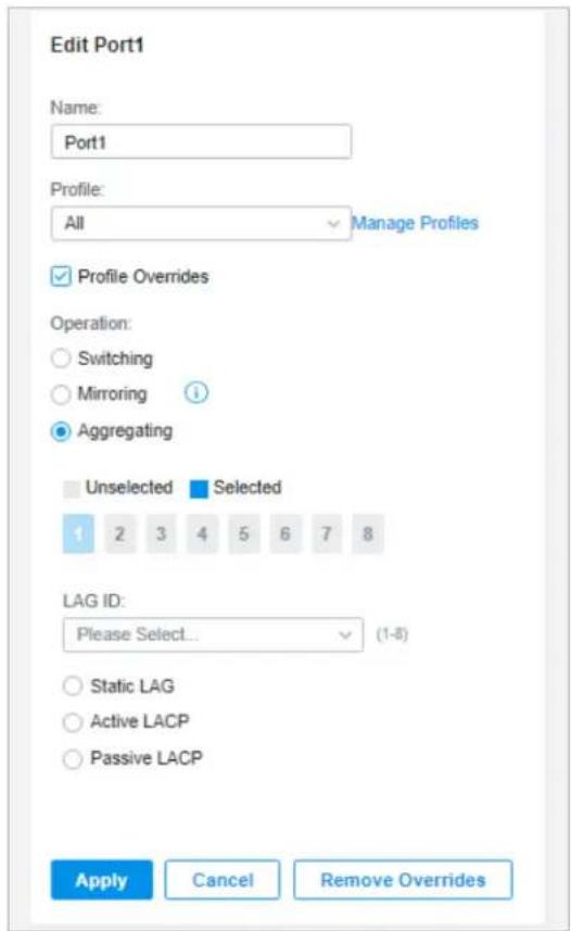
LAG ID Specify the LAG ID of the LAG. Note that the LAG ID should be unique.
The valid value of the LAG ID is determined by the maximum number of LAGs supported by your switch. For example, if your switch supports up to 14 LAGs, the valid value ranges from 1 to 14.
Static LAG In Static LAG mode, the member ports are added to the LAG manually.
Active LACP/
Passive LACP
LACP extends the flexibility of the LAG configurations. In LACP, the switch uses LACPDU (Link Aggregation Control Protocol Data Unit) to negotiate the parameters with the peer end. In this way, the two ends select active ports and form the aggregation link.
Active LACP: In this mode, the port will take the initiative to send LACPDU.
Passive LACP: In this mode, the port will not send LACPDU before receiving the LACPDU from the peer end.
LAG
LAGs (Link Aggregation Groups) are logical interfaces aggregated, which can increase link bandwidth and enhance the connection reliability. You can view and edit the LAGs under the LAG tab. To configure physical ports as a LAG, refer to Configure a LAG.
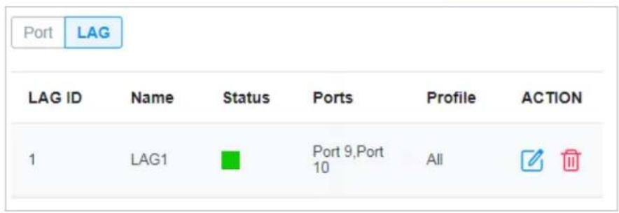
Status Displays the status in different colors.
: The LAG profile is Disable. To enable it, click to change the profile.
The port is enabled, but no device or client is connected to it.
The LAG ports are running at 1000 Mbps.
The LAG port are running at 10/100 Mbps.
Ports Displays the port number of LAG ports.
Profile Displays the profile applied to the port.
Action
☑: Click to edit the port name and configure the profile applied to the port.
: Click to delete the LAG. Once deleted, the ports will be configured as the default All profile and Switching operation. You can configure the ports under the Port tab.
Click to configure the LAG name and the applied profile.
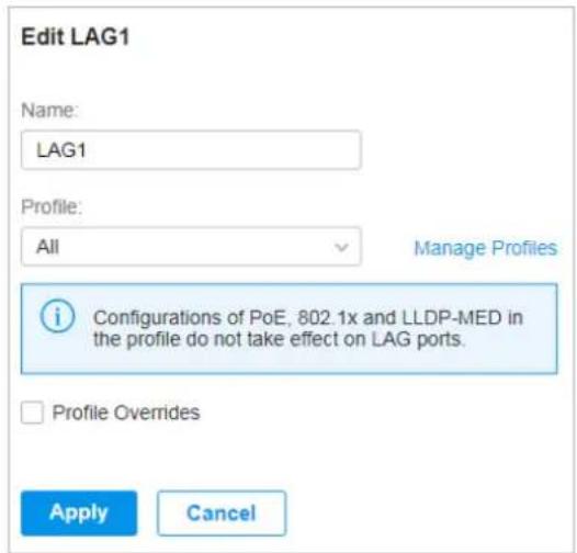
Name Enter the port name.
| Profile | Select the profile applied to the port from the drop-down list. Click Manage Profiles to jump to view and manage profiles. For details, refer to Configure Wired Networks. |
| Profile Overrides | Click the checkbox to override the applied profile. The parameters to be configured vary in Operation modes. |
With Profile Overrides enabled, you can reselect the LAG members and configure the following parameters.
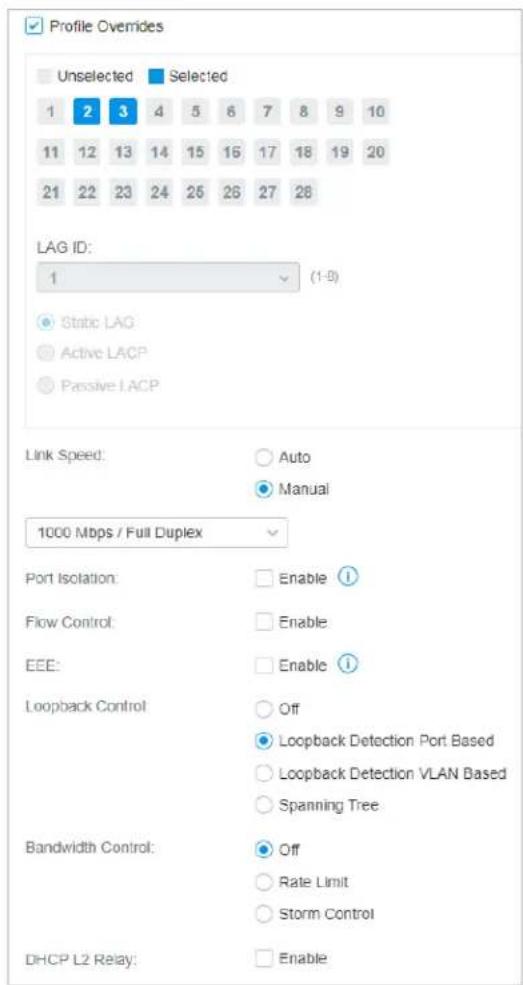
Link Speed Select the speed mode for the port.
Auto: The port negotiates the speed and duplex automatically.
Manual: Specify the speed and duplex from the drop-down list manually.
| Port Isolation Click the checkbox to enable Port Isolation. An isolated port cannot communicate directly with any other isolated ports, while the isolated port can send and receive traffic to non-isolated ports. | |
| Flow Control | With this option enabled, when a device gets overloaded it will send a PAUSE frame to notify the peer device to stop sending data for a specified period of time, thus avoiding the packet loss caused by congestion. |
| EEE Click the checkbox to enable EEE (Energy Efficient Ethernet) to allow power reduction. | |
| Loopback Control | Loopback refers to the routing of data streams back to their source in the network. You can disable loopback control for the network or choose a method to prevent loopback happening in your network.Off: Disable loopback control on the port. |
| Loopback Detection Port Based: Loopback Detection Port Based helps detect loops that occur on a specific port. When a loop is detected on a port, the port will be blocked. | |
| Loopback Detection VLAN Based: Loopback Detection VLAN Based helps detect loops that occur on a specific VLAN. When a loop is detected on a VLAN, the VLAN will be blocked. | |
| Spanning Tree: Select STP (Spanning Tree Protocol) to prevent loops in the network. STP helps block specific ports of the switches to build a loop-free topology and detect topology changes and automatically generate a new loop-free topology. To make sure Spanning Tree takes effect on the port, go to the Config tab and enable Spanning Tree on the switch. | |
| Bandwidth Control | Select the type of Bandwidth Control functions to control the traffic rate and traffic threshold on each port to ensure network performance.Off: Disable Bandwidth Control for the port. |
| Rate Limit: Select Rate limit to limit the ingress/egress traffic rate on each port. With this function, the network bandwidth can be reasonably distributed and utilized. | |
| Storm Control: Select Storm Control to allow the switch to monitor broadcast frames, multicast frames and UL-frames (Unknown unicast frames) in the network. If the transmission rate of the frames exceeds the specified rate, the frames will be automatically discarded to avoid network broadcast storm. | |
| Ingress Rate Limit | With Rate Limit selected, click the checkbox and specify the upper rate limit for receiving packets on the port. |
| Egress Rate Limit | With Rate Limit selected, click the checkbox and specify the upper rate limit for sending packets on the port. |
| Broadcast Threshold | With Storm Control selected, click the checkbox and specify the upper rate limit for receiving broadcast frames. The broadcast traffic exceeding the limit will be processed according to the Action configurations. |
| Multicast Threshold | With Storm Control selected, click the checkbox and specify the upper rate limit for receiving multicast frames. The multicast traffic exceeding the limit will be processed according to the Action configurations. |
| Unknown Unicast Threshold | With Storm Control selected, click the checkbox and specify the upper rate limit for receiving unknown unicast frames. The traffic exceeding the limit will be processed according to the Action configurations. |
| DHCP L2 Relay Click the checkbox to enable DHCP L2 Relay for the network. | |
| Action With Storm Control selected, select the action that the switch will take when the traffic exceeds its corresponding limit. | |
| Drop: With Drop selected, the port will drop the subsequent frames when the traffic exceeds the limit. | |
| Shutdown: With Shutdown selected, the port will be shutdown when the traffic exceeds the limit. | |
| Recover Time | With Shutdown selected as the Action, specify the recover time, and the port will be opened after the specified time. |
Config
In Config, click the sections to configure the features applied to the selected switch(es), including the general settings, services, and networks.
■ General
In General, you can specify the device name and LED settings of the switch, and categorize it via device tags.
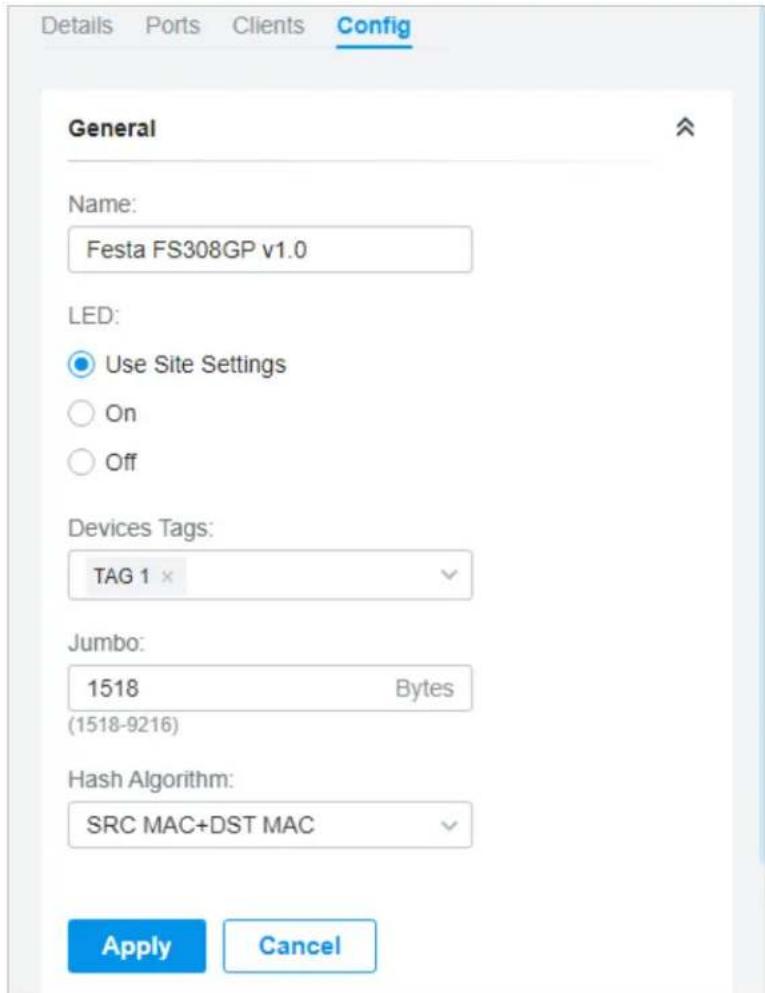
| Name (Only for configuring a single device) Specify a name of the device. | |
| LED | Select the way that device's LEDs work.Use Site Settings: The device's LED will work following the settings of the site. To view and modify the site settings, refer toServices.On/Off: The device's LED will keep on/off. |
| Device Tags Select a tag from the drop-down list or create a new tag to categorize the device. | |
| Jumbo Configure the size of jumbo frames. By default, it is 1518 bytes.Generally, the MTU (Maximum Transmission Unit) size of a normal frame is 1518 bytes. If you want the switch supports to transmit frames of which the MTU size is greater than 1518 bytes, you can configure the MTU size manually here. | |
| Hash Algorithm | Select the Hash Algorithm, based on which the switch can choose the port to forward the received packets. In this way, different data flows are forwarded on different physical links to implement load balancing.SRC MAC: The computation is based on the source MAC addresses of the packets.DST MAC: The computation is based on the destination MAC addresses of the packets.SRC MAC+DST MAC: The computation is based on the source and destination MAC addresses of the packets.SRC IP: The computation is based on the source IP addresses of the packets.DST IP: The computation is based on the destination IP addresses of the packets.SRC IP+DST IP: The computation is based on the source and destination IP addresses of the packets. |
■ VLAN Interface
In VLAN Interface, you can configure Management VLAN and different VLAN interface for the switch. The general information of the existing VLAN interface are displayed in the table.
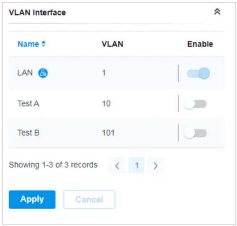
To configure a single VLAN interface, hover the mouse on the entry and click to edit the settings.
VLAN Interface > Edit Interface

IPv4
Management VLAN:

Enable


The controller will fail to manage your devices with wrong Management VLAN configurations. If you are not sure about your network conditions and the potential impact of any configurations, we recommend that you keep the default configurations. Refer to the Configuration Guide before you configure this feature.
IP Address Mode:
○ Static
DHCP
Use Fixed IP Address:

Enable

Fallback IP Address:

Enable

Fallback IP Address:
192 . 168 . 0 . 1
Fallback IP Mask:
255.255.255.0
Fallback Gateway:
(Optional)
DHCP Option12:
(Optional)
DHCP Mode:
None
DHCP Server
DHCP Relay
IPv6
IPv6:

Enable
Apply
Cancel
| Management VLAN | Click the checkbox if you want to use the VLAN interface as Management VLAN. Note that the controller will fail to manage your devices with wrong Management VLAN configurations. If you are not sure about your network conditions and the potential impact of any configurations, we recommend that you keep the default configurations.The management VLAN is a VLAN created to enhance the network security. Without Management VLAN, the configuration commands and data packets are transmitted in the same network. There are risks of unauthorized users accessing the management page and modifying the configurations. A management VLAN can separate the management network from the data network and lower the risks. |
| IP Address Mode (when Management VLAN enabled) | Select a mode for the interface to obtain its IP address, and the VLAN will communicate with other networks including VLANs with the IP address.Static: Assign an IP address to the interface manually, specify the IP Address and Subnet Mask for the interface.When the VLAN interface is set as the Management VLAN, it is optional for you to specify the Default Gateway and Primary/Secondary DNS for the interface.DHCP: Assign an IP address to the interface through a DHCP server.When you want to let device use a fixed IP address, enable Use Fixed IP Address and specify the Network and IP Address based on needs.When the VLAN interface is set as the Management VLAN, you can further enable Fallback IP Address, and specify the Fallback IP Address, Fallback IP Mask, and Fallback Gateway (optional). If the VLAN interface fails to get an IP address from the DHCP server, the fallback IP address will be used for the interface. |
| DHCP Option 12 | When DHCP is selected as the IP Address Mode, you can specify the hostname of the DHCP client in the field. The DHCP client will use option 12 to tell the DHCP server their hostname. |
| DHCP Mode Select a mode for the clients in the VLAN to obtain their IP address.None: Do not use DHCP to assign IP addresses.DHCP Server: Assign an IP address to the clients through a DHCP server.When DHCP Server is selected, you can specify the DHCP Range, and the IP addresses in the range can be assigned to the clients in the VLAN. Also, it is optional for you to specify the DHCP Option 138, Primary/Secondary DNS, Default Gateway, and Lease Time. DHCP Option 138 informs the DHCP client of the controller's IP address when the client sends a request to the DHCP server, and specify Option 138 as the controller's IP address here. Lease Time decides how long the client can use the assigned IP address.DHCP Relay: It allows clients in the VLAN to obtain IP addresses from a DHCP server ion different subnet. When DHCP Relay is selected, specify the IP address of the DHCP server in Server Address. | |
IPv6 Click the checkbox to enable IPv6.
Mode Select a mode for the clients in the VLAN to obtain their IPv6 address.
Dynamic IP (SLAAC/DHCPv6): If your ISP uses Dynamic IPv6 address assignment, either DHCPv6 or SLAAC+Stateless DHCP, select Dynamic IP (SLAAC/DHCPv6)
Static: Enter the static IPv6 address, prefix length, primary DNS server, and secondary DNS server information received from your ISP.
When choosing Dynamic IP (SLAAC/DHCPv6), select whether to get the DNS address dynamically from your ISP or designate the DNS address manually.
Get Dynamic DNS: The DNS address will be automatically assigned by the ISP.
Use the Following DNS Addresses: Enter the DNS address provided by the ISP.
■ Static Route
In Static Route, you can configure entries of static route for the switch. The general information of the existing static route entries are displayed in the table. For an existing static route, click ☑ to edit the settings, and click ☐ to delete it.
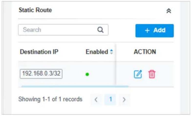
To add a new static route entry, click and configure the parameters.
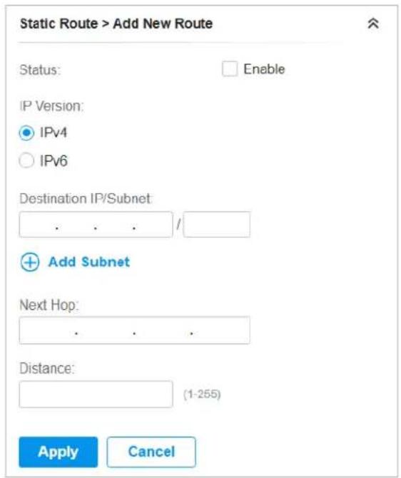
Status Click the checkbox to enable or disable the static route.
IP Version Select IPv4 or IPv6.
Destination IP/Subnet When IP Version is IPv4, specify Destination IP/Subnet. When IP Version is IPv6, specify Destination IP/Prefix Length. They identify the network traffic which the Static Route entry controls.
You can click + Add Subnet to specify multiple entries or click 📄 to delete them.
Next Hop Specify the IP address for your devices to forward the corresponding network traffic.
Distance Specify the priority of a static route. It is used to decide the priority among routes to the same destination. Among routes to the same destination, the route with the lowest distance value will be recorded into the routing table.
■ Services
In Services, you can configure Management VLAN, Loopback Control and SNMP.
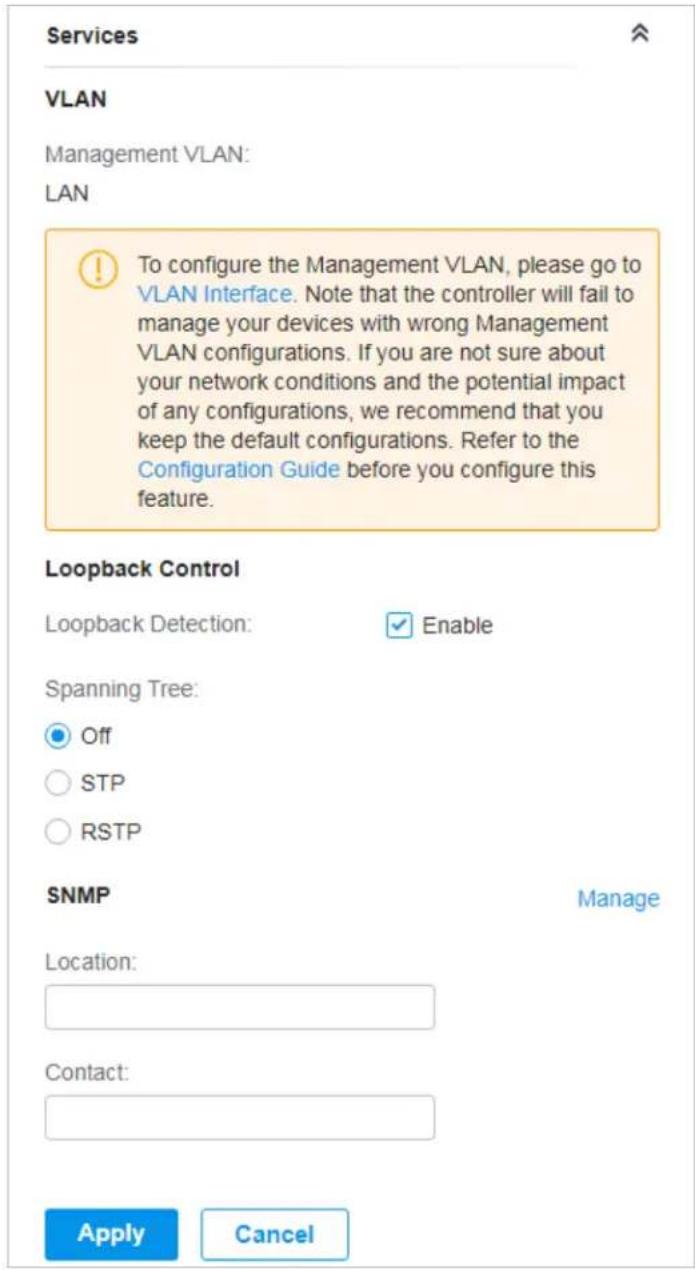
Management VLAN Display the name of the current Management VLAN.
To configure the Management VLAN, please go to Config > VLAN Interface. Note that the controller will fail to manage your devices with wrong Management VLAN configurations. If you are not sure about your network conditions and the potential impact of any configurations, we recommend that you keep the default configurations.
The management VLAN is a VLAN created to enhance the network security. Without Management VLAN, the configuration commands and data packets are transmitted in the same network. There are risks of unauthorized users accessing the management page and modifying the configurations. A management VLAN can separate the management network from the data network and lower the risks.
| Loopback Detection | When enabled, the switch checks the network regularly to detect the loopback. Note that Lopback Detection and Spanning Tree are not available at the same time. |
| Spanning Tree | Select a mode for Spanning tree. This feature is available only when Loopback Detection is disabled. Off: Disable Spanning Tree on the switch. STP: Enable STP (Spanning Tree Protocol) to prevent loops in the network. STP helps to block specific ports of the switches to build a loop-free topology and detect topology changes and automatically generate a new loop-free topology. RSTP: Enable RSTP (Rapid Spanning Tree Protocol) to prevent loops in the network. RSTP provides the same features as STP with faster spanning ree convergence. Priority: When STP/RSTP enabled, specify the priority for the swith in Spanning Tree. In STP/RSTP, the switch with the highest priority will be selected as the root of the spanning tree. The switch with the lower value has the higher priority. |
| SNMP | (Only for configuring a single device) Configure SNMP to write down the location and contact detail. You can also click Manage to jump to Settings > Services > SNMP, and for detailed configuration of SNMP service, refer to SNMP. |
■ Manage Device
In Manage Device, you can upgrade the device's firmware version manually, move it to another site, synchronize the configurations with the controller and forget the switch.
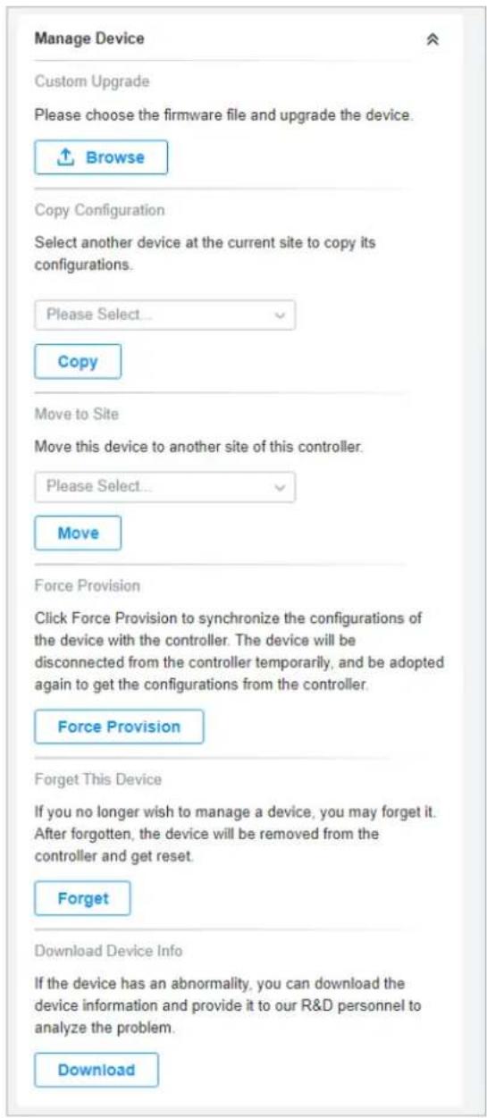
| Custom Upgrade | ClickBrowseand choose a file from your computer to upgrade the device. When upgrading, the device will be rebooted and readopted by the Controller. You can also check the box ofUpgrade all devices of the same modelin the site after the firmware file is uploaded. |
| Copy Configuration Select another device at the current site to copy its configurations. | |
| Move to Site | Select a site which the device will be moved to. After moving to another site, device configurations on the prior site will be replaced by that on the new site, and its traffic history will be cleared. |
| Force Provision | (Only for configuring a single device) ClickForce Provisionto synchronize the configurations of the device with the Controller. The device will lose connection temporarily, and be adopted to the controller again to get the configurations from the controller. |
| Forget This Device | Click Forgetand then the device will be removed from the Controller. Once forgotten, all configurations and history related to the device will be wiped out. |
| Download Device Info | If the device has an abnormality, you can download the device information and provide it to our R&D personnel to analyze the problem.⚠ Note:Firmware updates are required for earlier devices to obtain complete information. |
4.2 Monitor Switches
One panel and two tabs are provided to monitor the device in the Properties window: Monitor Panel, Details, and Clients.
Monitor Panel
The monitor panel displays the switch's ports and uses colors and icons to indicate the connection status and port type. When the switch is pending or disconnected, all ports are disabled.
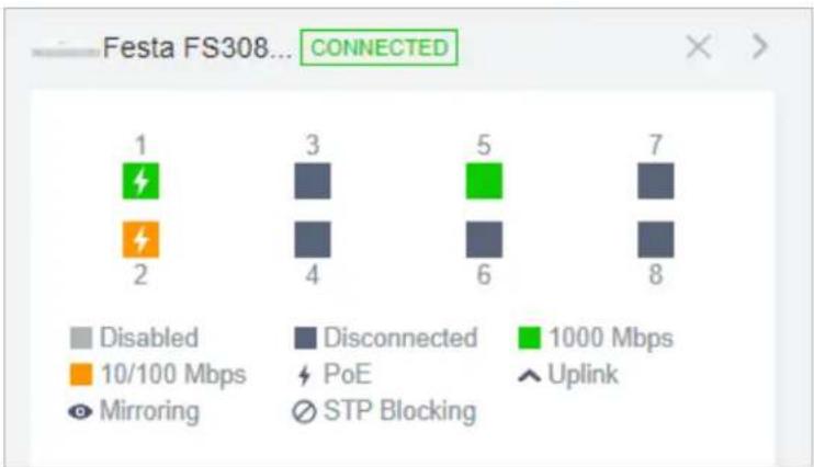
| PoE | A PoE port connected to a powered device (PD). |
| Uplink | An uplink port connected to WAN. |
| Mirroring | A mirroring port that is mirroring another switch port. |
| STP Blocking | A port in the Blocking status in Spanning Tree. It receives and sends BPDU (Bridge Protocol Data Unit) packets to maintain the spanning tree. Other packets are dropped. |
You can hover the cursor over the port icon (except disabled ports) for more details. The displayed information varies due to connection status and port type.
| Port | 3 |
| Name | Port3 |
| Status | 1000 Mbps Full Duplex |
| Tx Bytes | 343.59 MB |
| Rx Bytes | 353.98 MB |
| Profile | All |
| PoE Power | 4.3 W |
Status Displays the negotiation speed of the port.
Tx Bytes Displays the amount of data transmitted as bytes.
Rx Bytes Displays the amount of data received as bytes.
Profile Displays the name of profile applied to the port, which defines how the packets in both ingress and egress directions are handled. For detailed configuration, refer to Create Profiles.
PoE Power Displays the PoE power supply for the PD device.
Uplink Displays the name of device connected to the uplink port.
Mirroring From Displays the name of port that is mirrored.
LAG ID Displays the name of ports that are aggregated into a logical interface.
Details
In Details, you can view the basic information, traffic information, and radio information of the device to know the device's running status.
Overview
In Overview, you can view the basic information of the device. The listed information will be varied due to the device's model and status.
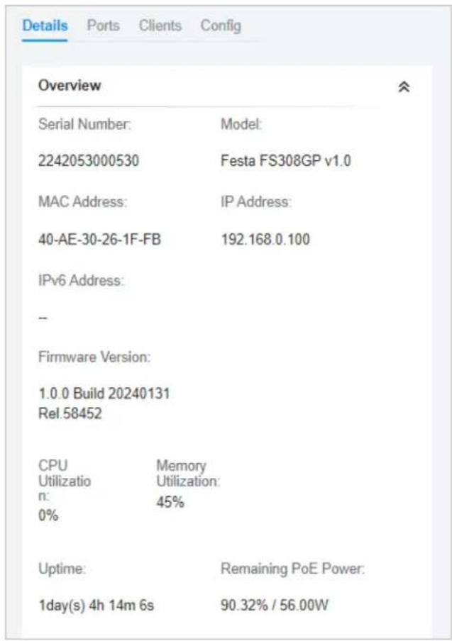
■ Uplink (Only for the switch connected to a controller-managed gateway/switch in Connected status)
Click Uplink to view the uplink information, including the uplink port, the uplink device, the negotiation speed, and transmission rate.
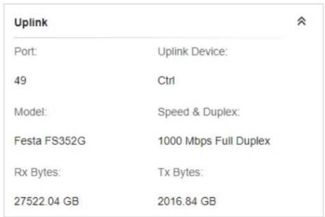
■ Downlink (Only for the switch connected to controller-managed devices in Connected status) Click Downlink to view the downlink information, including the downlink ports, devices model and MAC address as well as negotiation speed.
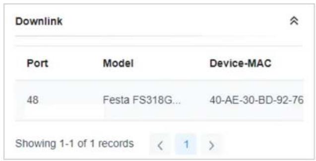
Clients
In Clients, you can view the information of clients connected to the switch, including the client name, IP address and the connected port. You can click the client name to open its Properties window.
| # | Name | IP Address |
| 7 | OC200_72C6FB | 192.168.0.132 |
| 8 | TP-Link-PC | 192.168.0.145 |
| Showing 1-2 of 2 records | < 1 > | |
5 Configure and Monitor APs
In the Properties window, you can configure one or some APs connected to the Controller and monitor the performanc. Configurations changed in the Properties window will be applied only to the selected AP(s). By default, all configurations are synchronized with the current site.
To open the Properties window, click the entry of an AP, or click Batch Action, and then Batch Config to select APs for batch configuration. A monitor panel and several tabs are listed in the Properties window. Most features to be configured are gathered in the Config tab, such as IP, radios, SSID, and VLAN, while other tabs are mainly used to monitor the device.
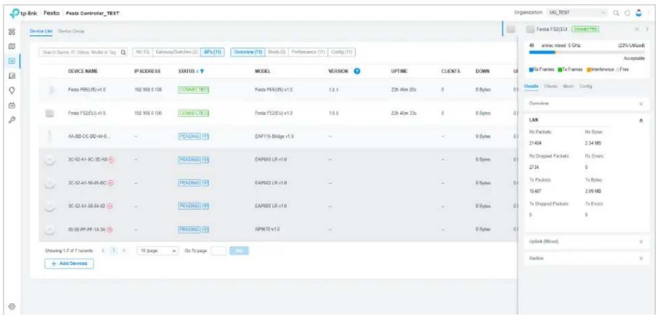
① Note:
- The available functions in the window vary due to the model and status of the device.
• In Batch Config, you can only configure the selected devices, and the unaltered configurations will keep the current settings.
• In Batch Config, if some functions, such as the 5 GHz band, are available only on some selected APs, the corresponding configurations will not take effect. To configure them successfully, check the model of selected devices first.
5.1 Configure APs
In the Properties window, click Config and then click the sections to configure the features applied to the selected AP(s).
■ General
In General, you can specify the device name and LED settings of the AP, and categorize it via device tags.
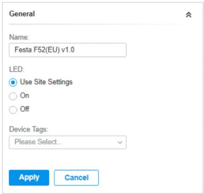
Name (Only for configuring a single device) Specify a name of the device.
| LED | Select the way that device's LEDs work. |
| Use Site Settings: The device's LED will work following the settings of the site. To view and modify the site settings, refer to Services. | |
| On/Off: The device's LED will keep on/off. | |
| Wi-Fi Control | (Only for Certain wall plate APs) Enable Wi-Fi Control, and it will take effect only when the LED feature is enabled. After enabling Wi-Fi Control, you can press the LED button on the AP to turn on/off the Wi-Fi and LED at the same time. |
| Device Tags Select a tag from the drop-down list or create a new tag to categorize the device. | |
■ IP Settings (Only for configuring a single device)
In IP Settings, select an IP mode and configure the parameters for the device.
If you select DHCP as the mode, make sure there is a DHCP server in the network and then the device will obtain dynamic IP address from the DHCP server automatically. If you want to let the device use a fixed IP address, you can enable Use Fixed IP Address, and set the network and IP address based on needs. Also, you can set a fallback IP address to hold an IP address in reserve for
the situation in which the device fails to get a dynamic IP address. Enable Fallback IP and then set the IP address, IP mask and gateway.
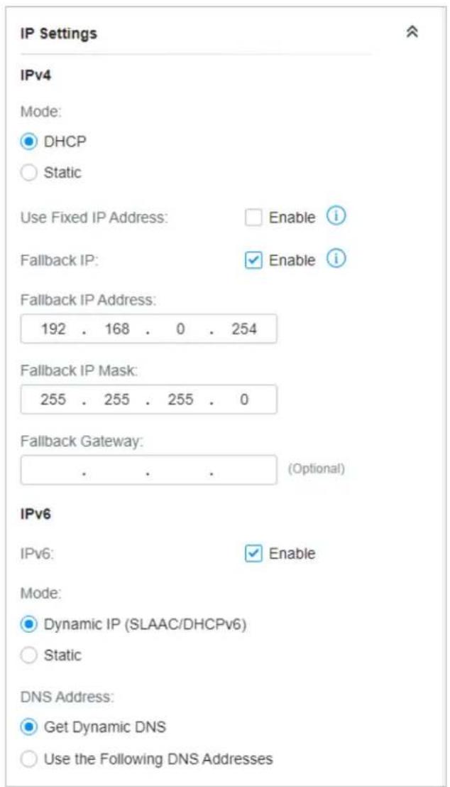
If you select Static as the mode, set the IP address, IP mask, gateway, and DNS server for the static address.
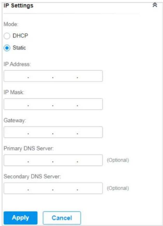
If you enable IPv6, select a mode for the AP to obtain an IPv6 address.
If you select Dynamic IP (SLAAC/DHCPv6) as the mode, choose whether to get the DNS address dynamically from your ISP or designate the DNS address manually.
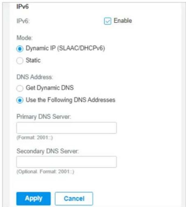
If you select Static as the mode, set the IPv6 address, prefix length, primary DNS server, and secondary DNS server information received from your ISP.
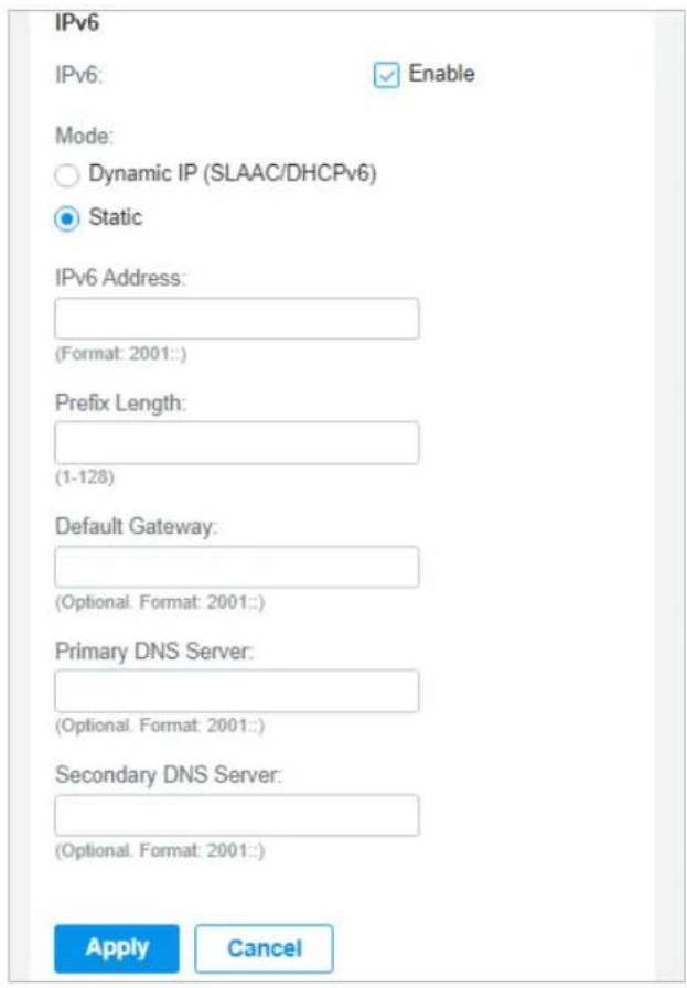
Radios
In Radios, you can control how and what type of radio signals the AP emits. Select each frequency band and configure the parameters. Different models support different bands.
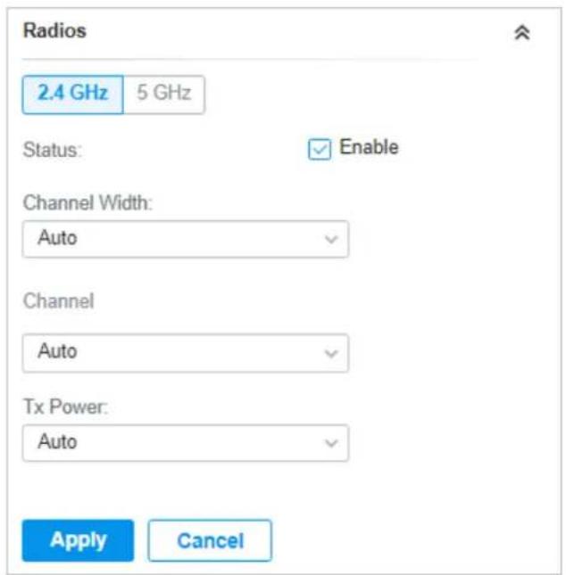
| Status If you disable the frequency band, the radio on it will turn off. | |
| Channel Width | Specify the channel width of the band. Different bands have different available options. We recommend using the default value. |
| Channel | Specify the operation channel of the AP to improve wireless performance. If you selectAutofor the channel setting, the AP scans available channels and selects the channel where the least amount of traffic is detected. |
| Tx Power | Specify the Tx Power (Transmit Power) in the 4 options: Low, Medium, High and Custom. The actual power of Low, Medium and High are based on the minimum transmit power (Min. Txpower) and maximum transmit power (Max. TxPower), which may vary in different countries and regions.Low: Min. TxPower + (Max. TxPower-Min. TxPower) * 20% (round off the value)Medium: Min. TxPower + (Max. TxPower-Min. TxPower) * 60% (round off the value)High: Max. TxPowerCustom: Specify the value manually. |
■ WLANs
In WLANs, you can apply the WLAN group to the AP and specify a different SSID name and password to override the SSID in the WLAN group. After that, clients can only see the new SSID and use the new password to access the network. To create or edit WLAN groups, refer to Configure Wireless Networks.
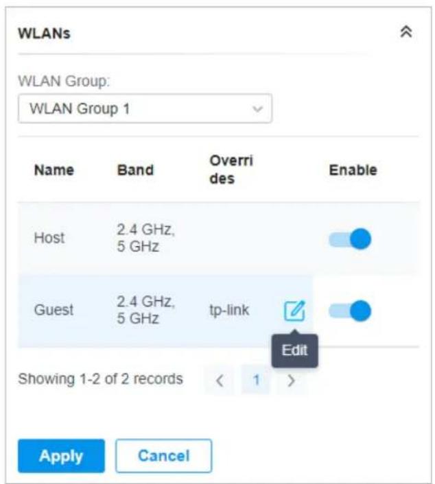
(Only for configuring a single device) To override the SSID, select a WLAN group, click in the entry and then the following page appears.
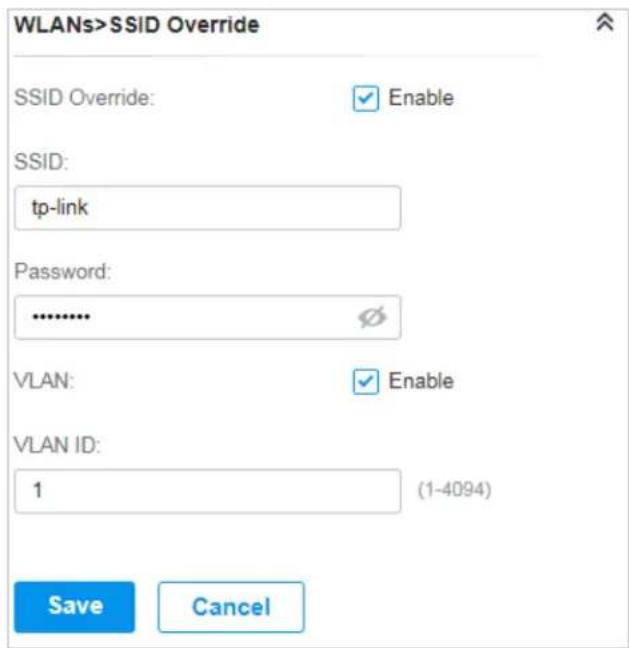
| SSID Override | Enable or disable SSID Override on the AP. If SSID Override enabled, specify the new SSID and password to override the current one. |
| VLAN | Enable or disable VLAN. If VLAN enabled, enter a VLAN ID to add the new SSID to the VLAN. |
■ Services
In Services, you can enable Management VLAN to protect your network and configure SNMP and web server parameters.
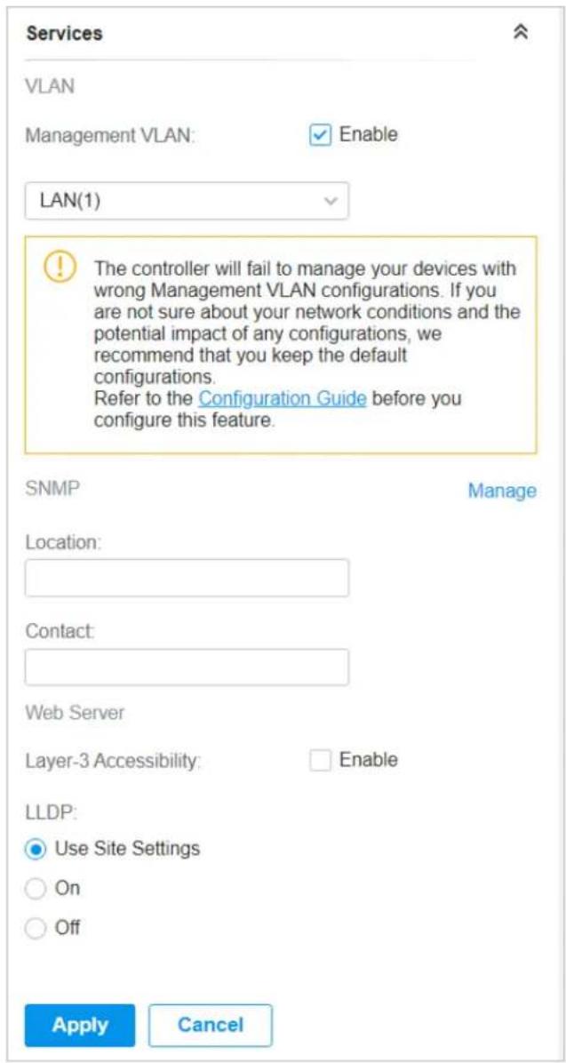
| Management VLAN | To configure Management VLAN, create a network in LAN first, and then select it as the management VLAN on this page. For details, refer to Configure Wireless Networks.The management VLAN is a VLAN created to enhance the network security. Without Management VLAN, the configuration commands and data packets are transmitted in the same network. There are risks of unauthorized users accessing the management page and modifying the configurations. A management VLAN can separate the management network from the data network and lower the risks. |
| SNMP | (Only for configuring a single device) Configure SNMP to write down the location and contact detail. You can also click Manage to jump to Settings > Services > SNMP, and for detailed configuration of SNMP service, refer to SNMP. |
Layer-3 Accessibility
With this feature enabled, devices from a different subnet can access controller-managed devices.
LLDP LLDP (Link Layer Discovery Protocol) can help discover devices.
■ Smart Antenna (For certain outdoor APs)
In Smart Antenna, you can turn on the function to improve Wi-Fi performance for user-heavy scenarios through antenna array and intelligent algorithm. This help overcome obstacles and signal interference.
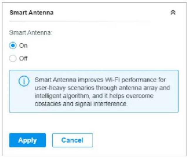
■ Advanced
In Advanced, configure Load Balance and QoS to make better use of network resources. Load Balance can control the client number associated to the AP, while QoS can optimize the performance when handling differentiated wireless traffics, including traditional IP data, and other types of audio, video, streaming media.
Select each frequency band and configure the following parameters and features.
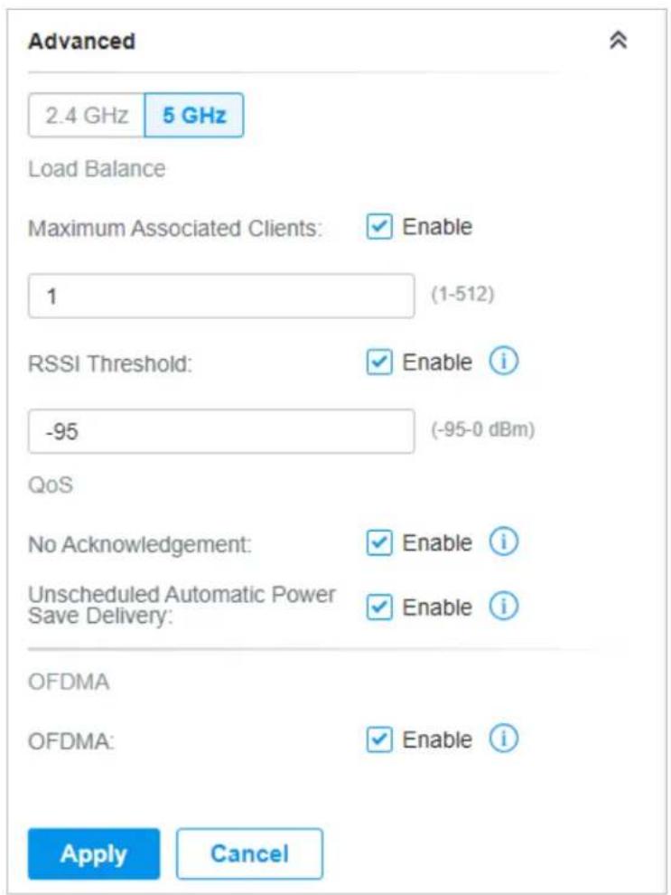
| Max Associated Clients | Enable this function and specify the maximum number of connected clients. If the connected client reaches the maximum number, the AP will disconnect those with weaker signals to make room for other clients requesting connections. |
| RSSI Threshold | Enable this function and enter the threshold of RSSI (Received Signal Strength Indication). If the client's signal strength is weaker than the threshold, the client will lose connection with the AP. |
| No Acknowledgment | Enable this function to specify that the APs will not acknowledge frames with QoS No Ack. Enabling No Acknowledgment can bring more efficient throughput, but it may increase error rates in a noisy Radio Frequency (RF) environment. |
| Unscheduled Automatic Power Save Delivery | When enabled, this function can greatly improve the energy-saving capacity of clients. |
| OFDMA (Only for AP supporting 802.11 ax) Enable this feature to enable multiple users to transmit data simultaneously, and it will greatly improves speed and efficiency. Note that the benefits of OFDMA can be fully enjoyed only when the clients support OFDMA. | |
■ Manage Device
In Manage Device, you can upgrade the device's firmware version manually, move it to another site, synchronize the configurations with the controller and forget the AP.
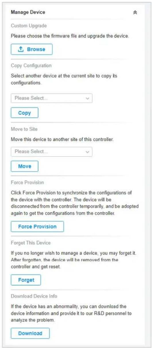
| Custom Upgrade | ClickBrowseand choose a file from your computer to upgrade the device. When upgrading, the device will be rebooted and readopted by the controller. You can also check the box ofUpgrade all devices of the same modelin the site after the firmware file is uploaded. |
| Copy Configuration Select another device at the current site to copy its configurations. | |
| Move to Site | Select a site which the device will be moved to. After moving to another site, device configurations on the prior site will be replaced by that on the new site, and its traffic history will be cleared. |
| Force Provision | (Only for configuring a single device) ClickForce Provisionto synchronize the configurations of the device with the controller. The device will lose connection temporarily, and be adopted to the controller again to get the configurations from the controller. |
| Forget this AP | Click Forgetand then the device will be removed from the controller. Once forgotten, all configurations and history related to the device will be wiped out. |
| Download Device Info | If the device has an abnormality, you can download the device information and provide it to our R&D personnel to analyze the problem.⚠ Note:Firmware updates are required for earlier devices to obtain complete information. |
5.2 Monitor APs
One panel and three tabs are provided to monitor the device in the Properties window: Monitor Panel, Details, Clients, and Mesh.
Monitor Panel
The monitor panel illustrates the active channel information on each radio band, including the AP's operation channel, radio mode and channel utilization. Four colors are used to indicate the percentage of Rx Frames (blue), Tx Frames (green), Interference (orange), and Free bandwidth (gray).
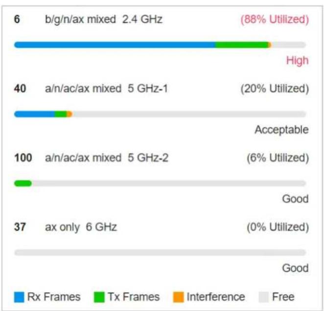
bar_stacked
| Category | Rx Frames | Tx Frames | Interference | Free | |---|---|---|---|---| | b/g/n/ax mixed 2.4 GHz | 6 | 0 | 0 | 88% Utilized | | High | 0 | 1 | 0 | 0 | | a/n/ac/ax mixed 5 GHz-1 | 40 | 3 | 1 | 20% Utilized | | Acceptable | 0 | 0 | 0 | 0 | | a/n/ac/ax mixed 5 GHz-2 | 100 | 2 | 0 | 6% Utilized | | Good | 0 | 0 | 0 | 0 | | ax only 6 GHz | 37 | 0 | 0 | 0% Utilized | | Good | 0 | 0 | 0 | 0 |You can hover the cursor over the channel bar for more details.
| Ch.Util.(Busy/Rx/Tx) | 51% / 32% / 4% |
| Tx Pkts/Bytes | 4195 / 847.04 KB |
| Rx Pkts/Bytes | 24247 / 6.47 MB |
| Tx Error/Dropped | 0.0% / 0.0% |
| Rx Error/Dropped | 0.0% / 0.0% |
Ch.Util.(Busy/Rx/Tx) Displays channel utilization statistics.
Busy: Displays the sum of Tx, Rx, and also non-WiFi interference, which indicates how busy the channel is.
Rx: Indicates how often the radio is in active receive mode.
Tx: Indicates how often the radio is in active transmit mode.
Tx Pkts/Bytes Displays the amount of data transmitted as packets and bytes.
Rx Pkts/Bytes Displays the amount of data received as packets and bytes.
Tx Error/Dropped Displays the percentage of transmit packets that have errors and the percentage of packets that were dropped.
Rx Error/Dropped Displays the percentage of receive packets that have errors and the percentage of packets that were dropped.
Details
In Details, you can view the basic information, traffic information, and radio information of the device to know the device's running status.
Overview
In Overview, you can view the basic information of the device. The listed information varies due to the device's status.
| Overview | |
| Serial Number: | MAC Address: |
| 2244769000573 | 60-83-E7-20-57-A8 |
| IP Address: | IPv6 Address: |
| 192.168.0.106 | -- |
| Model: | Firmware Version: |
| Festa F52(EU) v1.0 | 1.0.0 Build 20240329 Rel. 5 3172 |
| CPU Utilization: | Memory Utilization: |
| 4% | 54% |
| Uptime: | |
| 23h 13m 1s | |
■ LAN (Only for devices in the Connected status)
Click LAN to view the traffic information of the LAN port, including the total number of packets, the total size of data, the total number of packets loss, and the total size of error data in the process of receiving and transmitting data.
| LAN | |
| Rx Packets: | Rx Bytes: |
| 4724 | 936.73 KB |
| Rx Dropped Packets: | Rx Errors: |
| 0 | 0 |
| Tx Packets: | Tx Bytes: |
| 822 | 647.23 KB |
| Tx Dropped Packets: | Tx Errors: |
| 0 | 0 |
■ Uplink (Wired) (Only for devices in the Connected status)
Click Uplink (Wired) to view the traffic information related to the uplink AP, including the duplex type, negotiated speed, ratio of packets number and size, and dynamic downstream rate.
| Uplink (Wired) | |
| Uplink Device: | |
| Festa FR365 v1.0 | |
| Duplex: | Negotiated Speed: |
| Full Duplex | 1000 Mbps |
| Down Pkts/Bytes: | Up Pkts/Bytes: |
| 1297 / 248.31 KB | 613 / 189.24 KB |
| Activity Speed: i | |
| 369 B /s | |
■ Uplink (Wireless) (Only for devices in the Connected status)
Click Uplink (Wireless) to view the traffic information related to the uplink AP, including the signal strength, transmission rate, ratio of packets number and size, and dynamic downstream rate.
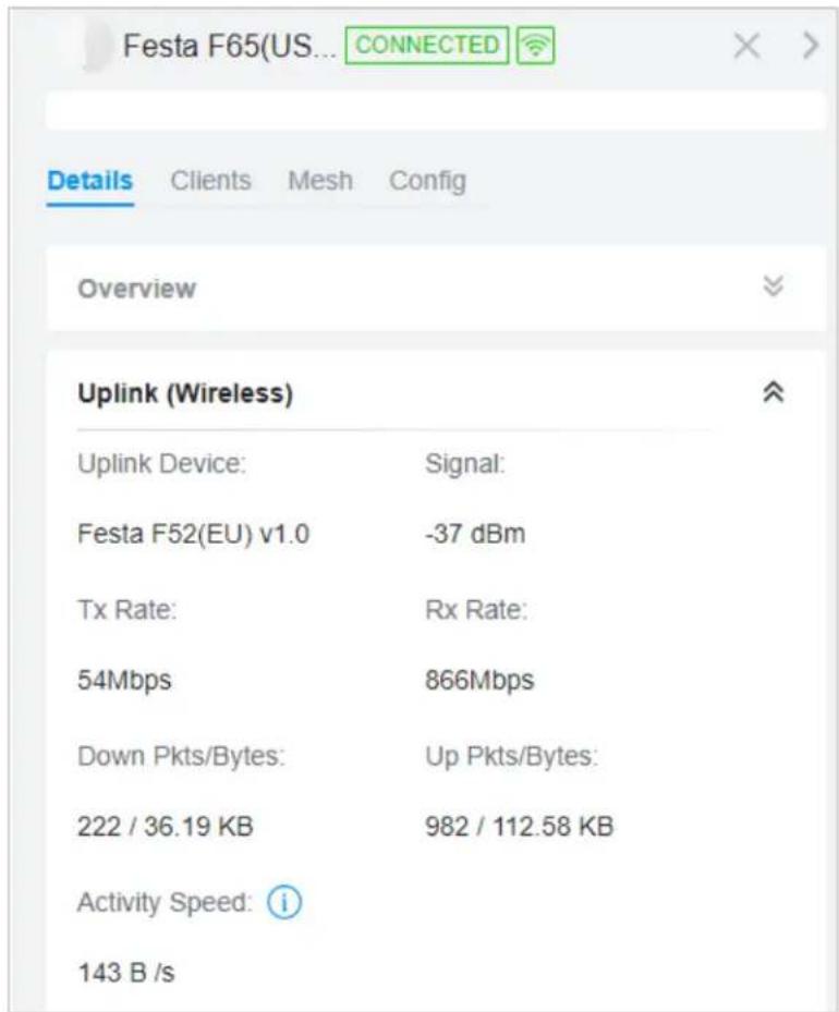
■ Radios (Only for devices in the Connected status)
Click Radio to view the radio information including the frequency band, the wireless mode, the channel width, the channel, and the transmitting power. You can also view parameters of receiving/transmitting data on each radio band.
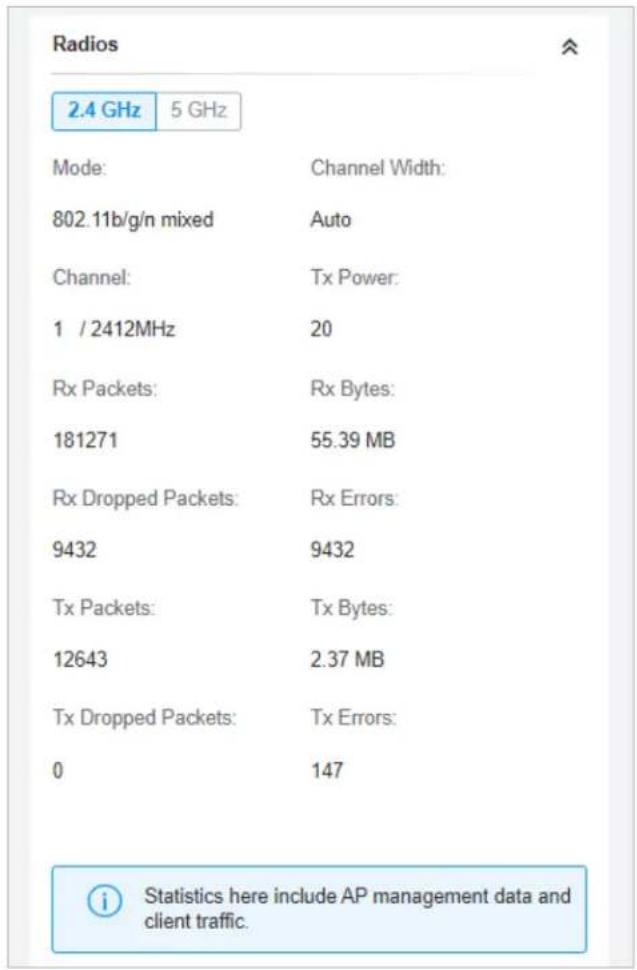
Clients
In Clients, you can view the information of users and guests connecting to the AP, including client name, MAC address and the connected SSID. Users are clients connected to the AP's SSID with Guest
Network disabled, while Guests are clients connected to that with Guest Network enabled. You can click the client name to open its Properties window.
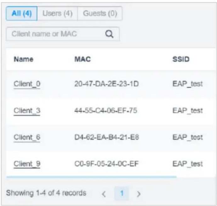
Mesh (Only for pending/connected/isolated devices supporting Mesh)
Mesh is used to establish a wireless network or expand a wired network through wireless connection on 5 GHz radio band. In practical application, it can help users to conveniently deploy APs without requiring Ethernet cable. After mesh network establishes, the APs can be configured and managed in the controller in the same way as wired APs. Meanwhile, because of the ability to self-organize and self-configure, mesh also can efficiently reduce the configuration.
Note that only certain AP models support Mesh, and the APs should be in the same site to establish a Mesh network.
To understand how mesh can be used, the following terms used in the Controller will be introduced:
| Root AP | The AP is managed by the Controller with a wired data connection that can be configured to relay data to and from mesh APs (downlink AP). |
| Isolated AP | When the AP which has been managed by the Controller before connects to the network wirelessly and cannot reach the gateway, it goes into the Isolated state. |
| Mesh AP | An isolated AP will become a mesh AP after establishing a wireless connection to the AP with network access. A pending AP, connecting wirelessly to the AP with network access, can also become a mesh AP after being adopted by the Controller. |
| Uplink AP/Downlink AP | Among mesh APs, the AP that offers the wireless connection for other APs is called uplink AP. A Root AP or an intermediate AP can be the uplink AP. And the AP that connects to the uplink AP is called downlink AP. An uplink AP can offer direct wireless connection for 4 downlink APs at most. |
Wireless Uplink The action that a downlink AP connects to the uplink AP.
Hops
In a deployment that uses a root AP and more than one level of wireless uplink with intermediate APs, the uplink tiers can be referred to by root, first hop, second hop and so on. The hops should be no more than 3.
A common mesh network is shown as below. Only the root AP is connected by an Ethernet cable, while other APs have no wired data connection. Mesh allows the isolated APs to communicate with pre-configured root AP on the network. Once powered up, factory default or unadopted APs can detect the AP in range and make itself available for adoption in the controller.
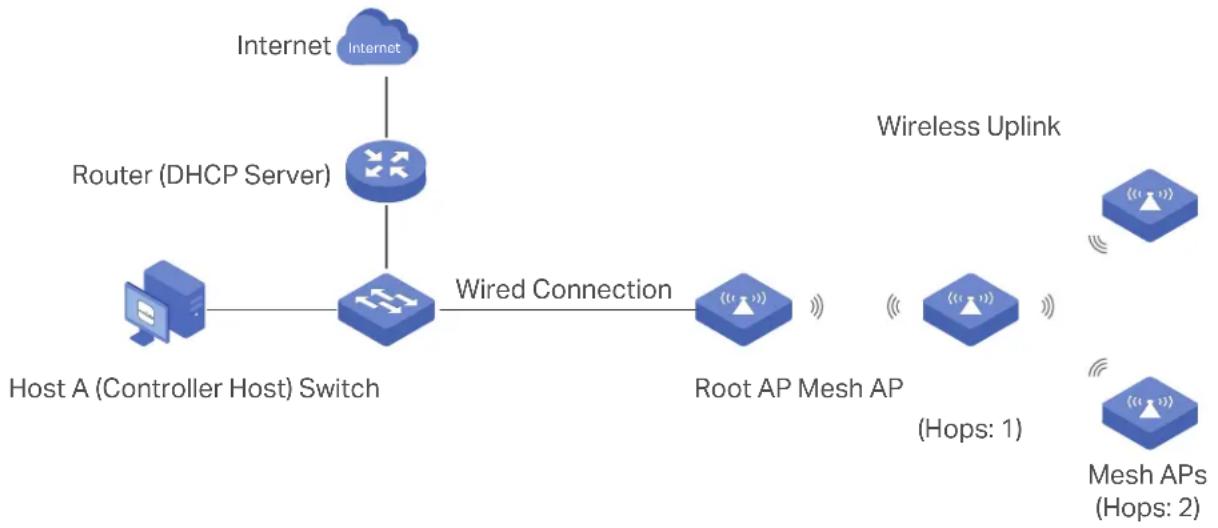
flowchart
graph LR
    A["Host A (Controller Host) Switch"] -->|Wired Connection| B["Root AP Mesh AP"]
    B --> C["Mesh APs (Hops: 2)"]
    D["Router (DHCP Server)"] -->|Wired Connection| B
    E["Internet"] --> F["Internet"]
    style A fill:#f9f,stroke:#333
    style B fill:#bbf,stroke:#333
    style C fill:#bfb,stroke:#333
    style D fill:#ffb,stroke:#333
    style E fill:#ffb,stroke:#333
    style F fill:#ffb,stroke:#333
After all the APs are adopted, a mesh network is established. The APs connected to the network via wireless connection also can broadcast SSIDs and relay network traffic to and from the network through the uplink AP.
To build a mesh network, follow the steps below:
1) Enable Mesh function.
2) Adopt the Root AP.
3) Set up wireless uplink by adopting APs in Pending(Wireless) or Isolated status.
- Go to Settings > Site to make sure Mesh is enabled.
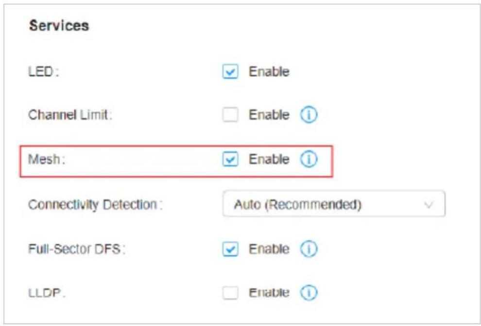
- Go to Devices to make sure that the Root AP has been adopted by the controller. The status of the Root AP is Connected.
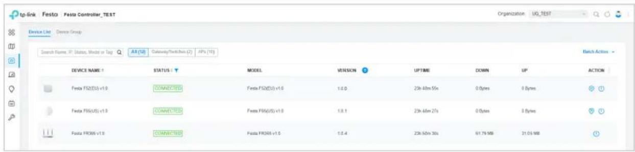
- Install the AP that will uplink the Root AP wirelessly. Make sure the intended location is within the range of Root AP. The APs that is waiting for Wireless Uplink includes two cases: factory default APs and APs that has been managed by the controller before. Go to Devices to adopt an AP in Pending (Wireless) status or link an isolated AP.
1) For the factory default AP, after powering on the device, the AP will be in Pending (Wireless) status with the icon PENDING in the controller. Click to adopt the AP in Pending (Wireless) status in the Devices list.
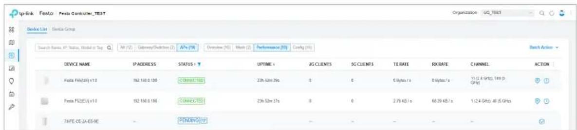
After adoption begins, the status of Pending (Wireless) AP will become Adopting (Wireless) and then Connected (Wireless). It should take roughly 2 minutes to show up Connected (Wireless) with the icon CONNECTED within your controller.
2) For the AP that has been managed by the Controller before and cannot reach the gateway, it goes into Isolated status when it is discovered by controller again. Click ♂ to connect the Uplink AP in the Devices list.
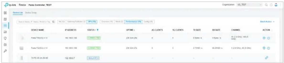
The following page will be shown as below, click Link to connect the Uplink AP.
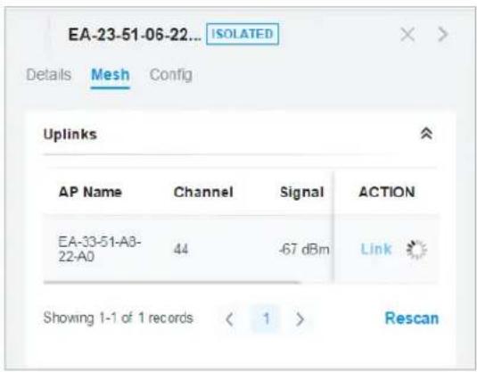
Once mesh network has been established, the AP can be managed by the controller in the same way as a wired AP. You can click the AP's name in the Devices list, and click Mesh to view and configure the mesh parameters of the AP in the Properties window.
In Mesh, if the selected AP is an uplink AP, this page lists all downlink APs connected to the AP.
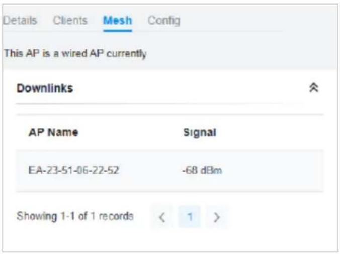
If the selected AP is a downlink AP, this page lists all available uplink APs and their channel, signal strength, hop, and the number of downlink APs. You can click Rescan to search the available uplink APs and refresh the list, and click Link to connect the uplink AP and build up a mesh network.
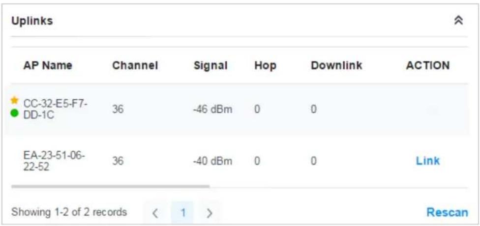

The icon appears before the priority uplink AP of the downlink AP. If you want to set another AP as the priority AP, click Link in Action column.

The icon appears before the current uplink AP of the downlink AP.

Tips:
- You can manually select the priority uplink AP that you want to connect in the uplink AP list. To build a mesh network with better performance, we recommend that you select the uplink AP with the strongest signal, least hop and least downlink AP.
- Auto Failover is enabled by default, and it allows the controller automatically select an uplink AP for the isolated AP to establish Wireless Uplink. And the controller will automatically select a new uplink AP for the mesh APs when the original uplink fails. For more details about Mesh global configurations, refer to the Mesh feature in Services.
Configure the Network with Festa Cloud-Based Controller
This chapter guides you on how to configure the network with the Festa Cloud-Based Controller. As the command center and management platform at the heart of the network, the Controller provides a unified approach to configuring enterprise networks comprised of gateways, switches, and wireless access points. The chapter includes the following sections:
• 1 Configure Wired Networks
• 2 Configure Wireless Networks
• 3 Network Security
• 4 Transmission
- 5 Configure VPN
- 6 Create Profiles
• 7 Authentication
• 8 Services
1 Configure Wired Networks
Wired networks enable your wired devices and clients including the gateway, switches, APs and PCs to connect to each other and to the internet.
As shown in the following figure, wired networks consist of two parts: Internet and LAN.
Wired Networks
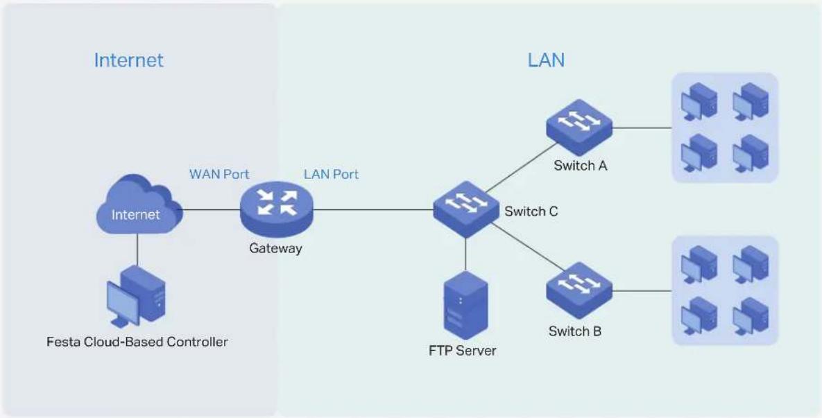
flowchart
graph LR
    A["Internet"] --> B["Festa Cloud-Based Controller"]
    B --> C["Gateway"]
    C --> D["LAN Port"]
    D --> E["Switch A"]
    D --> F["Switch B"]
    E --> G["Switch C"]
    F --> H["FTP Server"]
For Internet, you determine the number of WAN ports on the gateway and how they connect to the internet. You can set up an IPv4 connection and IPv6 connection to your internet service provider (ISP) according to your needs. The parameters of the internet connection for the gateway depend on which connection types you use. For an IPv4 connection, the following internet connection types are available: Dynamic IP, Static IP, PPPoE, L2TP, and PPTP. For an IPv6 connection, the following internet connection types are available: Dynamic IP (SLAAC/ DHCPv6), Static IP, PPPoE, 6to4 Tunnel, and Pass-Through (Bridge). And, when more than one WAN port is configured, you can configure Load Balancing to optimize the resource utilization if needed.
For LAN, you configure the wired internal network and how your devices logically separate from or connect to each other by means of VLANs and interfaces. Advanced LAN features include IGMP Snooping, DHCP Server and DHCP Options, PoE, Voice Network, Port Isolation, Spanning Tree, LLDP-MED, and Bandwidth Control.
1. 1 Set Up an Internet Connection
Configuration
To set up an internet connection, follow these steps:
1) Configure the number of WAN ports on the gateway based on needs.
2) Configure WAN Connections. You can set up the IPv4 connection, IPv6 connection, or both.
3) (Optional) Configure Load Balancing if more than one WAN port is configured.
Select WAN Mode Configure WAN Connections (Optional) Configure Load Balancing
Select a site from the drop-down list of Organization. Go to Settings > Wired Networks > Internet to load the following page. In WAN Mode, configure the number of WAN ports deployed by the gateway and other parameters. Then click Apply.
WAN Mode

WAN Settings Overrides:


- With WAN Settings Overrides disabled, the WAN settings of the newly adopted Festa gateway in standalone mode will take effect on the controller.
- When WAN Settings Overrides is turned on, the gateway will use the configurations on the Controller after adoption. Please make sure the configurations are correct. Otherwise the gateway may be unable to access the internet after adoption.
- If the number of preconfigured WAN ports does not match the number of WAN ports enabled in the adopted Festa gateway, the gateway will automatically reboot after adoption.
Gateway Model
Festa FR205 v1

WAN Ports.
USB Modem
WAN

WAN/LAN1

WAN/LAN2
Online Detection Interval:
Custom

Custom Time:
10
Seconds
(1-3600)

Online Detection results will influence whether Load Balancing and Link Backup features take effect. The smaller the online detection interval, the faster Load Balancing and Link Backup features will respond, and meanwhile more detection packets will be sent.
WAN Settings Overrides
With this option disabled, the WAN settings of the newly adopted gateway in standalone mode will take effect on the controller.
When this option is turned on, the gateway will use the configurations on the Controller after adoption. Please make sure the configurations are correct. Otherwise the gateway may be unable to access the internet after adoption. If the adopted device does not support some pre-configurations, the relevant configurations will be deleted after adoption.
Gateway Model Specify the gateway model and version. If you change the gateway, follow the web instructions to select WAN ports and copy WAN port settings.
If the number of preconfigured WAN ports does not match the number of WAN ports enabled in the adopted gateway, the gateway will automatically reboot after adoption.
Online Detection Interval
Select how often the WAN ports detect WAN connection status. If you don't want to enable online detection, select Disable.
Online Detection results will influence whether Load Balancing and Link Backup features take effect. The smaller the online detection interval, the faster Load Balancing and Link Backup features will respond, and meanwhile more detection packets will be sent.
Select WAN Mode
Configure WAN Connections
(Optional) Configure Load Balancing

Note:
The number of configurable WAN ports is decided by WAN Mode.
- Set Up USB Modem Connection
Select a site from the drop-down list of Organization. Go to Settings > Wired Networks > Internet. In the WAN Ports Config section, click the edit icon of USB Modem and configure the parameters.
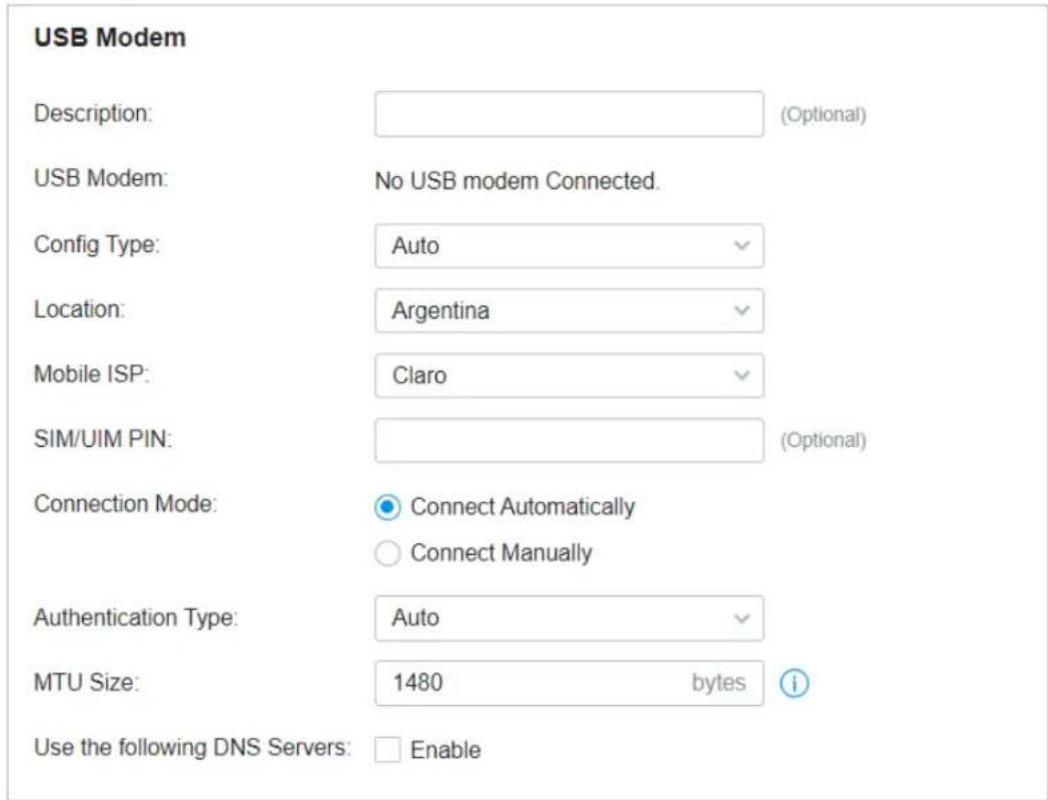
Description Enter a description for identification.
USB Modem Display whether a USB modem is connected to the device and the name of the connected USB modem.
Config Type Select a configuration type for the USB modem.
Auto: Use the Location and Mobile ISP information below for configuration.
Manually: Enter the Dial Number, APN, Username, and password provided by your Mobile ISP.
Location Select your location.
Mobile ISP Select your mobile ISP.
| Message Display the current status of the SIM card. | |
| SIM/UIM PIN (Optional) Enter the PIN of your SIM card. | |
| The field is required when the following information appears in the Message: PIN protection is enabled and the PIN is invalid. | |
| Connection Mode | Select the connection mode. |
| Connect Automatically: The gateway will use the USB modem to connect to the internet automatically. | |
| Connect Manually: You need to turn on/off the internet manually on the device page, refer toMonitor the Gateway. | |
| Authentication Mode | Select the Authentication mode for the USB modem. The default value is Auto, and it is recommended to keep the default value. |
| MTU Size Specify the MTU (Maximum Transmission Unit) of the USB WAN port. The default value is 1480, and it is recommended to keep the default value. | |
| Use the following DNS Servers | Enable the feature if you want to specify the Primary and Secondary DNS servers manually. |
- Set Up IPv4 Connection
Select a site from the drop-down list of Organization. Go to Settings > Wired Networks > Internet. In the WAN Ports Config section, click the edit icon of a WAN port and configure the Connection Type according to the service provided by your ISP.
Connection Type
Dynamic IP: If your ISP automatically assigns the IP address and the corresponding parameters, choose Dynamic IP.
Static IP: If your ISP provides you with a fixed IP address and the corresponding parameters, choose Static IP.
PPPoE: If your ISP provides you with a PPPoE account, choose PPPoE.
L2TP: If your ISP provides you with an L2TP account, choose L2TP.
PPTP: If your ISP provides you with a PPTP account, choose PPTP.
■ Dynamic IP
Choose Connection Type as Dynamic IP and configure the parameters.
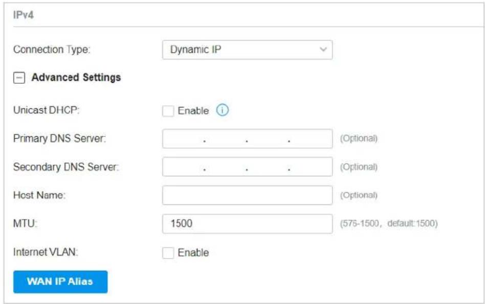
| Unicast DHCP With this option enabled, the gateway will require the DHCP server to assign the IP address by sending unicast DHCP packets. Usually you need not to enable the option. | |
| Primary DNS Server / Secondary DNS Server | Enter the IP address of the DNS server provided by your ISP if there is any. |
| Host Name Enter a name for the gateway. | |
| MTU Specify the MTU (Maximum Transmission Unit) of the WAN port.MTU is the maximum data unit transmitted in the physical network. When the connection type is Dynamic IP, MTU can be set in the range of 576-1500 bytes. The default value is 1500. | |
| Internet VLAN Add the WAN port to a VLAN and you need to specify the VLAN ID. Generally, you don't need to manually configure it unless required by your ISP. | |
| Internet VLAN Priority | Priority is only available when Internet VLAN is enabled. The Internet VLAN Priority function helps to prioritize the internet traffic based on your needs. You can determine the priority level for the traffic by specifying the tag. The tag ranges from 0 to 7. None means the packet will be forwarded without any operation. |
| WAN IP Alias WAN IP Alias supports configuring multiple IP addresses on one WAN port, and these IP addresses can be used to configure virtual server and other functions. | |
■ Static IP
Choose Connection Type as Static IP and configure the parameters.
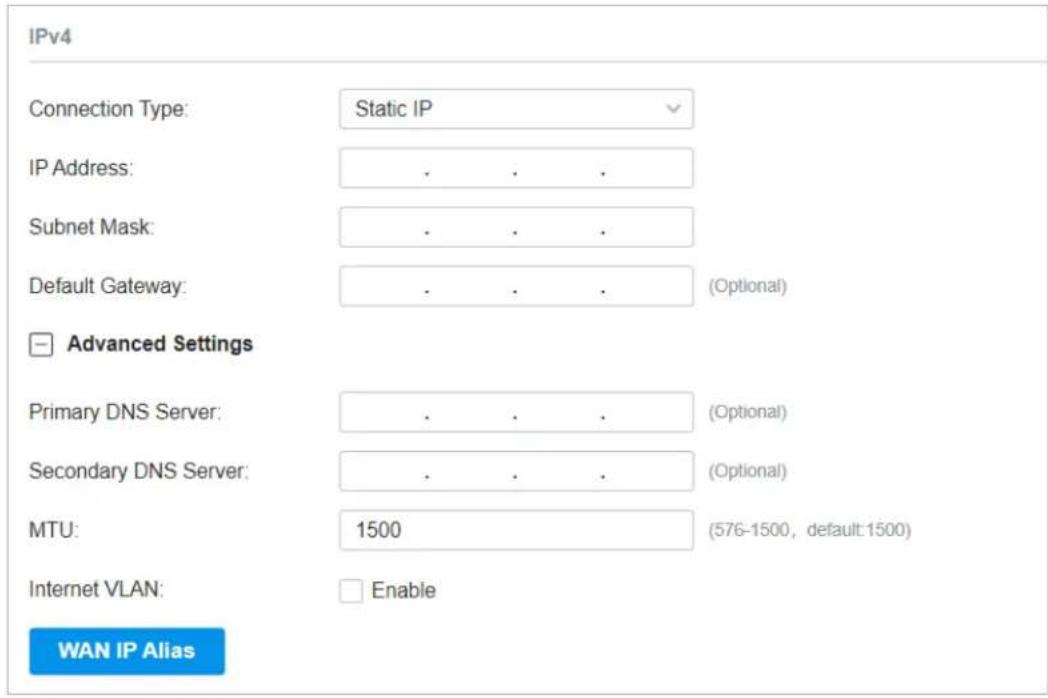
| IP Address Enter the IP address provided by your ISP. | |
| Subnet Mask Enter the subnet mask provided by your ISP. | |
| Default Gateway Enter the default gateway provided by your ISP. | |
| Primary DNS Server / Secondary DNS Server | Enter the IP address of the DNS server provided by your ISP if there is any. |
| MTU Specify the MTU (Maximum Transmission Unit) of the WAN port.MTU is the maximum data unit transmitted in the physical network. When the connection type is Static IP, MTU can be set in the range of 576-1500 bytes. The default value is 1500. | |
| Internet VLAN Add the WAN port to a VLAN and you need to specify the VLAN ID. Generally, you don't need to manually configure it unless required by your ISP. | |
| Internet VLAN Priority | Priority is only available when Internet VLAN is enabled. The Internet VLAN Priority function helps to prioritize the internet traffic based on your needs. You can determine the priority level for the traffic by specifying the tag. The tag ranges from 0 to 7. None means the packet will be forwarded without any operation. |
| WAN IP Alias WAN IP Alias supports configuring multiple IP addresses on one WAN port, and these IP addresses can be used to configure virtual server and other functions. | |
■ PPPoE
Choose Connection Type as PPPoE and configure the parameters.
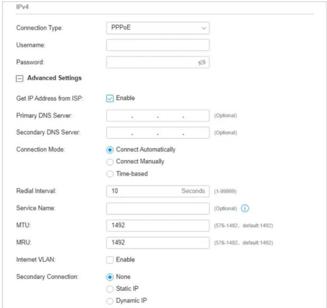
Username Enter the PPPoE username provided by your ISP.
| Password Enter the PPPoE password provided by your ISP. | |
| Get IP address from ISP | With this option enabled, the gateway gets IP address from ISP when setting up the WAN connection.With this option disabled, you need to specify theIP Addressprovided by your ISP. |
| Primary DNS Server / Secondary DNS Server | Enter the IP address of the DNS server provided by your ISP if there is any. |
| Connection Mode Connect Automatically: The gateway activates the connection automatically when the connection is down. You need to specify the Redial Interval, which decides how often the gateway tries to redial after the connection is down. | |
| Connect Manually: You can manually activate or terminate the connection. | |
| Time-Based: During the specified period, the gateway will automatically activate the connection. You need to specify the Time Range when the connection is up. | |
| Service Name Keep it blank unless your ISP requires you to configure it. | |
| MTU Specify the MTU (Maximum Transmission Unit) of the WAN port. | |
| MTU is the maximum data unit transmitted in the physical network. When the connection type is PPPoE, MTU can be set in the range of 576-1492 bytes. The default value is 1492. | |
| MRU Specify the MRU (Maximum Receive Unit) of the WAN port. MRU is the maximum data unit transmitted in the Data link layer. | |
| Internet VLAN Add the WAN port to a VLAN and you need to specify the VLAN ID. Generally, you don't need to manually configure it unless required by your ISP. | |
| Internet VLAN Priority | Priority is only available when Internet VLAN is enabled. The Internet VLAN Priority function helps to prioritize the internet traffic based on your needs. You can determine the priority level for the traffic by specifying the tag. The tag ranges from 0 to 7. None means the packet will be forwarded without any operation. |
| Secondary Connection Secondary connection is required by some ISPs. Select the connection type required by your ISP. | |
| None: Select this if the secondary connection is not required by your ISP. | |
| Static IP: Select this if your ISP provides you with a fixed IP address and subnet mask for the secondary connection. You need to specify the IP Address and Subnet Mask provided by your ISP. | |
| Dynamic IP: Select this if your ISP automatically assigns the IP address and subnet mask for the secondary connection. | |
L2TP
Choose Connection Type as L2TP and configure the parameters.
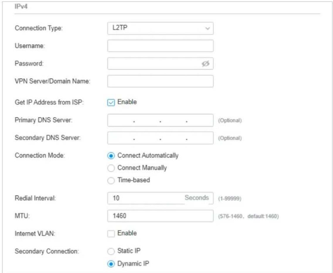
Username Enter the L2TP username provided by your ISP.
Password Enter the L2TP password provided by your ISP.
VPN Server / Domain Name Enter the VPN Server/Domain Name provided by your ISP.
Get IP address from ISP With this option enabled, the gateway gets IP address from ISP when setting up the WAN connection.
With this option disabled, you need to specify the IP address provided by your ISP.
Primary DNS Server / Secondary DNS Server Enter the IP address of the DNS server provided by your ISP if there is any.
Connection Mode Connect Automatically: The gateway activates the connection automatically when the connection is down. You need to specify the Redial Interval, which decides how often the gateway tries to redial after the connection is down.
Connect Manually: You can manually activate or terminate the connection.
Time-Based: During the specified period, the gateway will automatically activate the connection. You need to specify the Time Range when the connection is up.
MTU Specify the MTU (Maximum Transmission Unit) of the WAN port.
MTU is the maximum data unit transmitted in the physical network. When the connection type is L2TP, MTU can be set in the range of 576-1460 bytes. The default value is 1460.
Internet VLAN Add the WAN port to a VLAN and you need to specify the VLAN ID. Generally, you don't need to manually configure it unless required by your ISP.
Internet VLAN Priority Priority is only available when Internet VLAN is enabled. The Internet VLAN Priority function helps to prioritize the internet traffic based on your needs. You can determine the priority level for the traffic by specifying the tag. The tag ranges from 0 to 7. None means the packet will be forwarded without any operation.
Secondary Connection Select the connection type required by your ISP.
Static IP: Select this if your ISP provides you with a fixed IP address and subnet mask for the secondary connection. You need to specify the IP Address, Subnet Mask, Default Gateway (Optional), Primary DNS Server (Optional), and Secondary DNS Server (Optional) provided by your ISP.
Dynamic IP: Select this if your ISP automatically assigns the IP address and subnet mask for the secondary connection.
■ PPTP
Choose Connection Type as PPTP and configure the parameters.
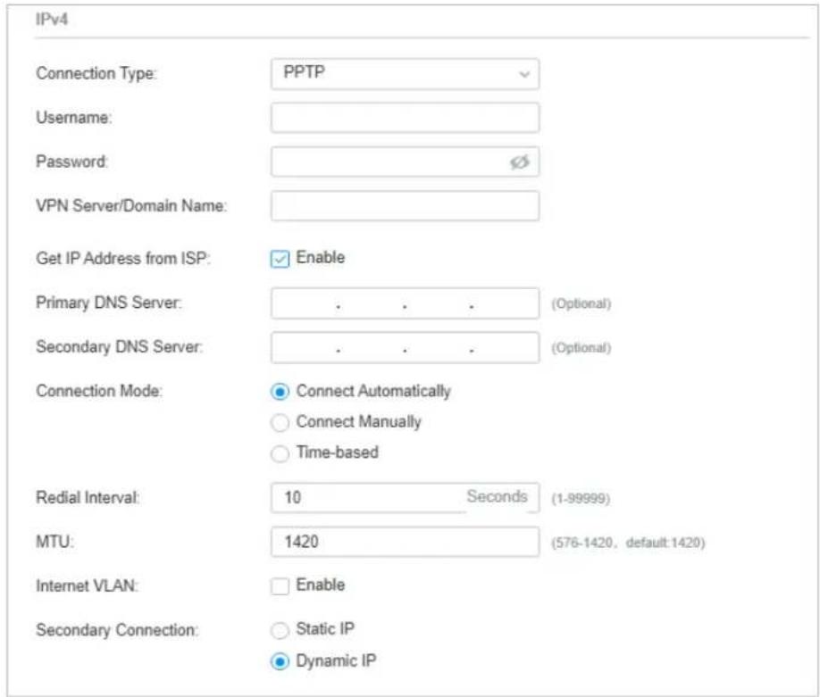
| Username Enter the PPTP username provided by your ISP. | |
| Password Enter the PPTP password provided by your ISP. | |
| VPN Server / Domain Name Enter the VPN Server/Domain Name provided by your ISP. | |
| Get IP address from ISP | With this option enabled, the gateway gets IP address from ISP when setting up the WAN connection.With this option disabled, you need to specify theIP addressprovided by your ISP. |
| Primary DNS Server / Secondary DNS Server | Enter the IP address of the DNS server provided by your ISP if there is any. |
| Connection Mode Connect Automatically: The gateway activates the connection automatically when the connection is down. You need to specify theRedial Interval, which decides how often the gateway tries to redial after the connection is down.Connect Manually: You can manually activate or terminate the connection.Time-Based: During the specified period, the gateway will automatically activate the connection. You need to specify theTime Rangewhen the connection is up. | |
| MTU Specify the MTU (Maximum Transmission Unit) of the WAN port. | |
| MTU is the maximum data unit transmitted in the physical network. When the connection type is PPTP, MTU can be set in the range of 576-1420 bytes. The default value is 1420. | |
| Internet VLAN Add the WAN port to a VLAN and you need to specify the VLAN ID. Generally, you don't need to manually configure it unless required by your ISP. | |
| Internet VLAN Priority | Priority is only available when Internet VLAN is enabled. The Internet VLAN Priority function helps to prioritize the internet traffic based on your needs. You can determine the priority level for the traffic by specifying the tag. The tag ranges from 0 to 7. None means the packet will be forwarded without any operation. |
| Secondary Connection Select the connection type required by your ISP. | |
| Static IP: Select this if your ISP provides you with a fixed IP address and subnet mask for the secondary connection. You need to specify the IP Address, Subnet Mask, Default Gateway (Optional), Primary DNS Server (Optional), and Secondary DNS Server (Optional) provided by your ISP. | |
| Dynamic IP: Select this if your ISP automatically assigns the IP address and subnet mask for the secondary connection. | |
- Set Up IPv6 Connection
For IPv6 connections, check the box to enable the IPv6 connection, select the internet connection type according to the requirements of your ISP.
Connection Type
Dynamic IP (SLAAC/DHCPv6): If your ISP uses Dynamic IPv6 address assignment, either DHCPv6 or SLAAC+Stateless DHCP, select Dynamic IP (SLAAC/DHCPv6).
Static IP: If your ISP provides you with a fixed IPv6 address, select Static IP.
PPPoE: If your ISP uses PPPoEv6, and provides a username and password, select PPPoE.
6to4 Tunnel: If your ISP uses 6to4 deployment for assigning IPv6 address, select 6to4 Tunnel. 6to4 is an internet transition mechanism for migrating from IPv4 to IPv6, a system that allows IPv6 packets to be transmitted over an IPv4 network. The IPv6 packet will be encapsulated in the IPv4 packet and transmitted to the IPv6 destination through IPv4 network.
Pass-Through (Bridge): In Pass-Through (Bridge) mode, the gateway works as a transparent bridge. The IPv6 packets received from the WAN port will be transparently forwarded to the LAN port and vice versa. No extra parameter is required.
■ Dynamic IP (SLAAC/DHCPv6)
Choose Connection Type as Dynamic IP (SLAAC/DHCPv6) and configure the parameters.
| Connection Type: | Dynamic IP (SLAAC/DHCPv6) |
| Get IPv6 Address: | AutomaticallyVia SLAAcVia DHCPv6Non-Address |
| Prefix Delegation: | Enable i |
| Prefix Delegation Size: | (48-64)i |
| DNS Address: | Get from ISP DynamicallyUse the Following DNS Addresses |
Get IPv6 Address Select the proper method whereby your ISP assigns IPv6 address to your gateway.
Automatically: With this option selected, the gateway will automatically select SLAAC or DHCPv6 to get IPv6 addresses.
Via SLAAC: With SLAAC (Stateless Address Auto-Configuration) selected, your ISP assigns the IPv6 address prefix to the gateway and the gateway automatically generates its own IPv6 address. Also, your ISP assigns other parameters including the DNS server address to the gateway.
Via DHCPv6: With DHCPv6 selected, your ISP assigns an IPv6 address and other parameters including the DNS server address to the gateway using DHCPv6.
Non-Address: With this option selected, the gateway will not get an IPv6 address.
| Prefix Delegation Select Enable to get an address prefix by DHCPv6 server from your ISP, or Disable to designate an address prefix for your LAN port manually. Clients in LAN will get an IPv6 address with this prefix. | |
| Prefix Delegation Size | With Prefix Delegation enabled, enter the Prefix Delegation Size to determine the length of the address prefix. If you are not sure about the value, you can ask your ISP. |
| DNS Address Select whether to get the DNS address dynamically from your ISP or designate the DNS address manually. | |
■ Static IP
Choose Connection Type as Static IP and configure the parameters.
| Connection Type: | Static IP | |
| IPv6 Address: | (Format: 2001::) | |
| Prefix Length: | (1-128) i | |
| Default Gateway: | (Format: 2001::) | |
| Primary DNS Server: | (Format: 2001::) | |
| Secondary DNS Server: | (Optional. Format: 2001::) |
IPv6 Address Enter the static IPv6 address information received from your ISP.
Prefix Length Enter the prefix length of the IPv6 address received from your ISP.
Default Gateway Enter the default gateway provided by your ISP.
Primary DNS Server Enter the IP address of the primary DNS server provided by your ISP.
Secondary DNS Server (Optional) Enter the IP address of the secondary DNS server, which provides redundancy in case the primary DNS server goes down.
■ PPPoE
Choose Connection Type as PPPoE and configure the following parameters. Then click Apply.
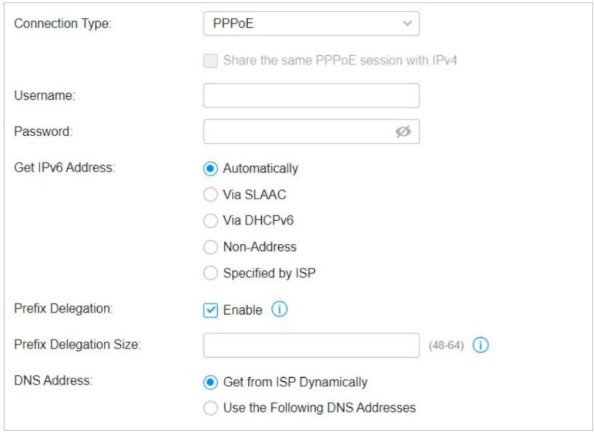
| Share the same PPPoE session with IPv4 | If your ISP provides only one PPPoE account for both IPv4 and IPv6 connections, and you have already established an IPv4 connection on this WAN port, you can check the box, then the WAN port will use the PPP session of IPv4 PPPoE connection to get the IPv6 address. In this case, you do not need to enter the username and password of the PPPoE account. If your ISP provides two separate PPPoE accounts for the IPv4 and IPv6 connections, or the IPv4 connection of this WAN port is not based on PPPoE, do not check the box and manually enter the username and password for the IPv6 connection. |
| Username Enter the username of your PPPoE account provided by your ISP. | |
| Password Enter the password of your PPPoE account provided by your ISP. | |
| Get IPv6 Address Select the proper method whereby your ISP assigns IPv6 address to your gateway. | |
| Automatically: With this option selected, the gateway will automatically select the method to get IPv6 addresses between SLAAC and DHCPv6. | |
| Via SLAAC: With SLAAC (Stateless Address Auto-Configuration) selected, your ISP assigns the IPv6 address prefix to the gateway and the gateway automatically generates its own IPv6 address. Also, your ISP assigns other parameters including the DNS server address to the gateway. | |
| Via DHCPv6: With DHCPv6 selected, your ISP assigns an IPv6 address and other parameters including the DNS server address to the gateway using DHCPv6. | |
| Non-Address: With this option selected, the gateway will not get an IPv6 address. | |
| Specified by ISP: With this option selected, enter the IPv6 address you get from your ISP. | |
| Prefix Delegation | Select Enable to get an address prefix by DHCPv6 server from your ISP, or Disable to designate an address prefix for your LAN port manually. Clients in LAN will get an IPv6 address with this prefix. |
| Prefix Delegation Size | With Prefix Delegation enabled, enter the Prefix Delegation Size to determine the length of the address prefix. If you are not sure about the value, you can ask your ISP. |
| DNS Address Select whether to get the DNS address dynamically from your ISP or designate the DNS address manually. | |
| Get from ISP Dynamically: The DNS address will be automatically assigned by the ISP. | |
| Use the Following DNS Addresses: Enter the DNS address provided by the ISP. | |
■ 6to4 Tunnel
Choose Connection Type as 6to4 Tunnel and configure the parameters.
IPv6
IPv6:
Enable
Connection Type:
6to4 Tunnel
DNS Address:
Get from ISP Dynamically
○ Use the Following DNS Addresses
DNS Address Select whether to get the DNS address dynamically from your ISP or designate the DNS address manually.
Get from ISP Dynamically: The DNS address will be automatically assigned by the ISP.
Use the Following DNS Addresses: Enter the DNS address provided by the ISP.
■ Pass-Through (Bridge)
Choose Connection Type as Pass-Through (Bridge) and no configuration is required for this type of connection.
Connection Type:
Pass-Through(Bridge)
- Set Up MAC Address
Select a site from the drop-down list of Organization. Go to Settings > Wired Networks > Internet. In the WAN Ports Config section, click the edit icon of a WAN port and configure the MAC address according to actual needs.
MAC Address
MAC Address:
○ Use Default MAC Address
Customize MAC Address
MAC Address:
MAC Address Use Default MAC Address: The WAN port uses the default MAC address to set up the internet connection. It's recommended to use the default MAC address unless required otherwise.
Customize MAC Address: The WAN port uses a customized MAC address to set up the internet connection and you need to specify the MAC address. Typically, this is required when your ISP bound the MAC address with your account or IP address. If you are not sure, contact the ISP.
Select WAN Mode Configure WAN Connections (Optional) Configure Load Balancing

Note:
Loading Balancing is only available when you configure more than one WAN port.
Select a site from the drop-down list of Organization. Go to Settings > Wired Networks > Internet to load the following page. In Load Balancing, configure the following parameters and click Apply.
Load Balancing
Load Balancing Weight:
1
1
Application Optimized Routing:
Enable
①
Link Backup:
Enable
Primary WAN:
Please Select...
V
Backup WAN:
Please Select...
V
Backup Mode:
○ Link Backup

Always Link Primary

Mode:
● Enable backup link when any primary WAN fails
○ Enable backup link when all primary WANs fail
Load Balancing Weight Specify the ratio of network traffic that each WAN port carries.
| Alternatively, you can click Pre-Populate to test the speed of WAN ports and automatically fill in the appropriate ratio according to test result. | |
| Application Optimized Routing | With Application Optimized Routing enabled, the gateway will consider the source IP address and destination IP address (or destination port) of the packets as a whole and record the WAN port they pass through. Then the packets with the same source IP address and destination IP address ( or destination port) will be forwarded to the recorded WAN port.This feature ensures that multi-connected applications work properly. |
| Link Backup | With Link Backup enabled, the gateway will switch all the new sessions from dropped lines automatically to another to keep an always on-line network. |
| Backup WAN / Primary WAN | The backup WAN port backs up the traffic for the primary WAN ports under the specified condition. |
Backup Mode Link Backup: The system will switch all the new sessions from dropped line automatically to another to keep an always on-link network.
Always Link Primary: Traffic is always forwarded through the primary WAN port unless it fails. The system will try to forward the traffic via the backup WAN port when it fails, and switch back when it recovers.
Mode Select whether to enable backup link when any primary WAN fails or all primary WANs fail.
1.2 Configure LAN Networks
Overview
The LAN function allows you to configure wired internal network. Based on 802.1Q VLAN, the Controller provides a convenient and flexible way to separate and deploy the network. The network can be logically segmented by departments, application, or types of users, without regard to geographic locations.
Configuration
To create a LAN, follow the guidelines:
1) Create a Network with specific purpose. For Layer 2 isolation, create a network as VLAN. To realize inter-VLAN routing, create a network as Interface, which is configured with a VLAN interface.
2) Create a port profile for the network. The profile defines how the packets in both ingress and egress directions are handled.
3) Assign the port profile to the desired ports of the switch to activate the LAN.
Create a Network Create a Port Profile Assign the Port Profile to the Ports
NOTE:
A default Network (default VLAN) named LAN is preconfigured as Interface and is associated with all LAN ports of the Gateway and all switch ports. The VLAN ID of the default Network is 1. The default Network can be edited, but not deleted.
- Select a site from the drop-down list of Organization. Go to Settings > Wired Networks > LAN > Networks to load the following page.

- Click + Create New LAN to load the following page, enter a name to identify the network, and select the purpose for the network.
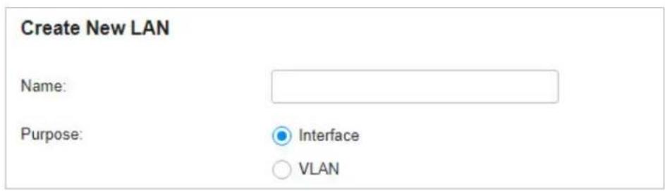
Purpose
Interface: Create the network with a Layer 3 interface, which is required for inter-VLAN routing.
VLAN: Create the network as a Layer 2 VLAN.
3. Configure the parameters according to the purpose for the network.
■ Interface
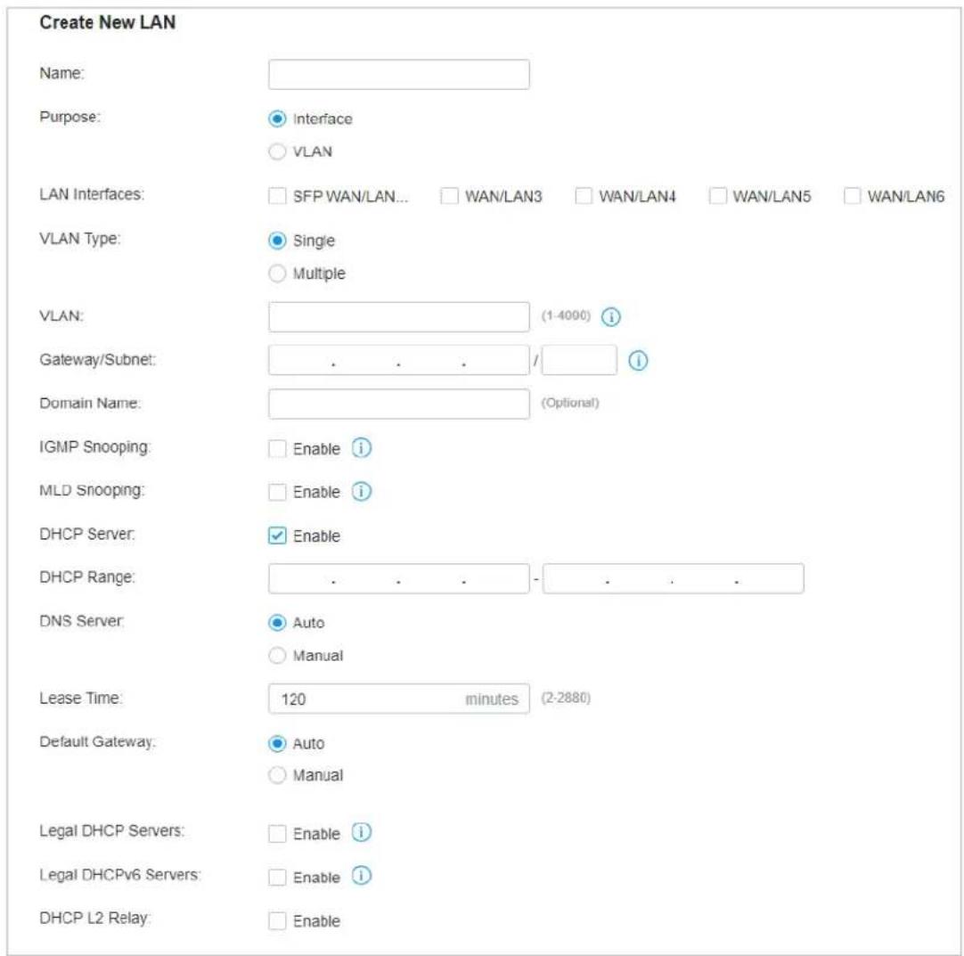
| LAN Interface | Select the physical interfaces of the Gateway that this network will be associated with. |
| VLAN Type Specify whether to use a single VLAN or multiple VLANs. When Multiple is selected, you can configure multiple VLANs for devices to access the LAN network. | |
| VLAN Enter a VLAN ID with the values between 1 and 4090. Each VLAN can be uniquely identified by VLAN ID, which is transmitted and received as IEEE 802.1Q tag in an Ethernet frame. | |
| Gateway/Subnet Enter the IP address and subnet mask in the CIDR format. The CIDR Notation here includes the IP address and subnet mask of the default gateway. The summary of the information that you entered will show up below in real time. | |
| Domain Name Enter the domain name. | |
| IGMP Snooping | Click the checkbox to monitor IGMP (Internet Group Management Protocol) traffic and thereby manage multicast traffic. |
| MLD Snooping With MLD Snooping enabled, Festa Switches can use MLD snooping to constrain the flooding of IPv6 multicast traffic by maintaining the relationship between multicast groups and their member ports. | |
| DHCP Server | Click the checkbox to allow the Gateway to serve as the DHCP server for this network. A DHCP server assigns IP addresses, DNS server, default gateway, and other parameters to all devices in the network. Deselect the box if there is already a DHCP server in the network. |
| DHCP Range Enter the starting and ending IP addresses of the DHCP address pool in the fields provided. For quick operation, click the Update DHCP Range beside the Gateway/Subnet entry to get the IP address range populated automatically, and edit the range according to your needs. | |
| DNS Server Select a method to configure the DNS server for the network. | |
| Auto: The DHCP server automatically assigns DNS server for devices in the network. It uses the IP address specified in the Gateway/Subnet entry as the DNS server address. | |
| Manual: Specify DNS servers manually. Enter the IP address of a server in each DNS server field. | |
| Lease Time Specify how long a client can use the IP address assigned from this address pool. | |
| Default Gateway Enter the IP address of the default gateway. | |
| Auto: The DHCP server automatically assigns default gateway for devices in the network. It uses the IP address specified in the Gateway/Subnet entry as the default gateway address. | |
| Manual: Specify default gateway manually. Enter the IP address of the default gateway in the field. | |
| Legal DHCP Servers | Click the checkbox to specify legal DHCP servers for the network. With legal DHCP servers configured, Festa Switches ensure that clients get IP addresses only from the DHCP servers specified here. |
| Legal DHCPv6 Servers | Click the checkbox to specify legal DHCPv6 servers for the network. With legal DHCPv6 servers configured, Festa Switches ensure that clients get IP addresses only from the DHCPv6 servers whose IPv6 addresses are specified here. |
| DHCP L2 Relay Click the checkbox to enable DHCP L2 Relay for the network. | |
You can configure advanced DHCP Options based on you needs. You can also click toCustom customize DHCP Options.

Advanced DHCP Options
Option 2:
Seconds
(Optional) i
Option 42:
. . .
• • •
(Optional)

Option 44:
. . .
(Optional) i
Option 60:
(Optional) i
Option 66:
(Optional) i
Option 67:
(Optional) i
Option 138:
. . .
(Optional) i
Option 252:
(Optional)

Custom
Custom 1

Code:
Please Select...
Type:
Value:
Option 2 Enter the value for DHCP Option 2. DHCP clients use this field to configure the time offset which specifies the offset of the client's subnet in seconds from Coordinated Universal Time (UTC).
Option 42 Enter the value for DHCP Option 42. DHCP clients use this field to configure the NTP server address.
Option 44 Enter the value for DHCP Option 44. DHCP clients use this field to configure the NetBIOS over TCP/IP name server.
| Option 60 | Enter the value for DHCP Option 60. DHCP clients use this field to optionally identify the vendor type and configuration of a DHCP client. Mostly it is used in the scenario where the APs apply for different IP addresses from different servers according to the needs. |
| Option 66 | Enter the value for DHCP Option 66. It specifies the TFTP server information and supports a single TFTP server IP address. |
| Option 67 | Enter the value for DHCP Option 67. It tells the client a path to a file from a TFTP server (Option 66) that will be retrieved and used to boot. That file needs to be a basic boot loader that will do any other required work. |
| Option 138 | Enter the value for DHCP Option 138. It is used in discovering the devices by the controller. |
Option 252 Enter the value for DHCP Option 252. It provides a DHCP client a URL to use to configure its proxy settings. It is defined in draft-ietf-wrec-wpad-01. If it was a statement like 'wpad-proxy-url', then only systems that understood it could use it (they would have to recognize that string and know how to handle it).
You can configure IPv6 connections for the LAN clients based on you needs. First, determine the method whereby the gateway assigns IPv6 addresses to the clients in the local network. Some clients may support only a few of these connection types, so you should choose it according to the compatibility of clients in the local network.

Configure IPv6
IPv6 Interface Type:
Gateway/Subnet:
DHCP Range:
Lease Time:
DHCPv6 DNS:
DHCPv6


natural_image
Two empty rectangular boxes with no text, numbers, or symbols inside.1440
minutes
(1-11520)
Auto
○ Manual
IPv6 Interface Type
Configure the type of assigning IPv6 address to the clients in the local network.
None: IPv6 connection is not enabled for the clients in the local network.
DHCPv6: The gateway assigns an IPv6 address and other parameters including the DNS server address to each client using DHCPv6.
SLAAC+Stateless DHCP: The gateway assigns the IPv6 address prefix to each client and the client automatically generates its own IPv6 address. Also, the gateway assigns other parameters including the DNS server address to each client using DHCPv6.
SLAAC+RDNSS: The gateway assigns the IPv6 address prefix to each client and the client automatically generates its own IPv6 address. Also, the gateway assigns other parameters including the DNS server address to each client using the RDNSS option in RA (Router Advertisement).
Pass-Through: Select this type if the WAN ports of the gateway use the Pass-Through for IPv6 connections.
With DHCPv6 selected, configure the following parameters.
Gateway/Subnet Enter the IP address and subnet mask in the CIDR format. The CIDR notation here includes the IP address and subnet mask of the default gateway. The summary of the information that you entered will show up below in real time.
DHCP Range Enter the starting and ending IP addresses of the DHCP address pool in the fields
provided. For quick operation, click the Update DHCP Range beside the Gateway/Subnet entry to get the IP address range populated automatically, and edit the range according to your needs.
| Lease Time This entry determines how long the assigned IPv6 address remains valid. Either keep the default 1440 minutes or change it if required by your ISP. | |
| DHCPv6 DNS | Select a method to configure the DNS server for the network. With Auto selected, the DHCP server automatically assigns DNS server for devices in the network. With Manual selected, enter the IP address of a server in each DNS server field. |
| With SLAAC+Stateless DHCP selected, configure the following parameters. | |
| Prefix Configure the IPv6 address prefix for each client in the local network. | |
| Manual Prefix: With Manual Prefix selected, enter the prefix in the Address Prefix field. | |
| Get from Prefix Delegation: With Get from Prefix Delegation selected, select the WAN port with Prefix Delegation configured, and the clients will get the address prefix from the Prefix Delegation. | |
| IPv6 Prefix ID | With Get from Prefix Delegation selected, enter the Prefix ID, which will be added to the prefix to obtain a /64 subnet. |
| The range of IPv6 Prefix ID is determined by the larger value of Prefix Delegation Size and Prefix Delegation Length (obtained from the ISP). Note that if the Prefix Delegation Length is larger than 64, the IPv6 Prefix ID cannot be obtained from Prefix Delegation, please select another method. In site view, go to Settings > Wired Network > Internet to configure Prefix Delegation Size. | |
| DNS Server Select a method to configure the DNS server for the network. | |
| Auto: With Auto selected, the DHCP server automatically assigns DNS server for devices in the network. | |
| Manual: With Manual selected, enter the IP address of a server in each DNS server field. | |
| With SLAAC+RDNSS selected, configure the following parameters. | |
| Prefix Configure the IPv6 address prefix for each client in the local network. | |
| Manual Prefix: With Manual Prefix selected, enter the prefix in the Address Prefix field. | |
| Get from Prefix Delegation: With Get from Prefix Delegation selected, select the WAN port with Prefix Delegation configured, and the clients will get the address prefix from the Prefix Delegation. | |
| IPv6 Prefix ID | With Set from Prefix Delegation selected, enter the Prefix ID, which will be added to the prefix to obtain a /64 subnet. |
| DNS Server Select a method to configure the DNS server for the network. | |
| Auto: With Auto selected, the DHCP server automatically assigns DNS server for devices in the network. | |
| Manual: With Manual selected, enter the IP address of a server in each DNS server field. | |
| With Pass-Through selected, configure the following parameters. | |
IPv6 Passthrough WAN Select the WAN port using Pass-Through (Bridge) for the IPv6 connection.
Create New LAN
Name:
Purpose:

○ Interface
VLAN
VLAN:

(1-4090, for example: 2-100,200)

Application:
Gateways and Switches
○ Switches Only
IGMP Snooping:
Enable i
MLD Snooping:
Enable i
Legal DHCP Servers:
Enable i


Legal DHCPv6 Servers:
Enable i


DHCP L2 Relay:
Enable
Save
Cancel
| VLAN Enter a VLAN ID with the values between 1 and 4090. Each VLAN can be uniquely identified by VLAN ID, which is transmitted and received as IEEE 802.1Q tag in an Ethernet frame. | |
| IGMP Snooping | Click the checkbox to monitor IGMP (Internet Group Management Protocol) traffic and thereby manage multicast traffic. |
| MLD Snooping With MLD Snooping enabled, Festa Switches can use MLD snooping to constrain the flooding of IPv6 multicast traffic by maintaining the relationship between multicast groups and their member ports. | |
| Legal DHCP Servers | Click the checkbox to specify legal DHCP servers for the network. With legal DHCP servers configured, Gateways and Switches ensure that clients get IP addresses only from the DHCP servers specified here. |
Legal DHCPv6 Servers
Click the checkbox to specify legal DHCPv6 servers for the network. With legal DHCPv6 servers configured, Festa Switches ensure that clients get IP addresses only from the DHCPv6 servers whose IPv6 addresses are specified here.
DHCP L2 Relay Click the checkbox to enable DHCP L2 Relay for the network.
- Click Save. The new LAN is added to the LAN list. You can click ☑ in the ACTION column to edit the LAN. You can click 📋 in the ACTION column to delete the LAN.

Create a Network
Create a Port Profile
Assign the Port Profile to the Ports
! Note:
- Three default port profiles are preconfigured on the controller. They can be viewed, but not edited or deleted.
All: In the All profile, all networks except the default network (LAN) are configured as Tagged Network, and the native network is the default network (LAN). This profile is assigned to all switch ports by default.
Disable: In the Disable profile, no networks are configured as the native network, Tagged Networks and Untagged Networks. With this profile assigned to a port, the port does not belong to any VLAN.
LAN: In the LAN profile, the native network is the default network (LAN), and no networks are configured as Tagged Networks and Untagged Networks.
- When a network is created, the system will automatically create a profile with the same name and configure the network as the native network for the profile. In this profile, the network itself is configured as the Untagged Networks, while no networks are configured as Tagged Networks. The profile can be viewed and deleted, but not edited.
- Go to Wired Networks > LAN > Profiles to load the following page.
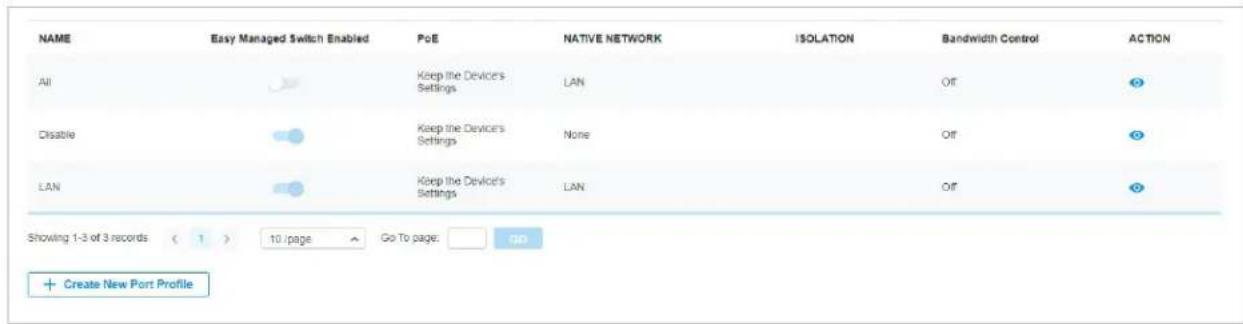
2. Click + Create New Port Profile to load the following page, and configure the following parameters.
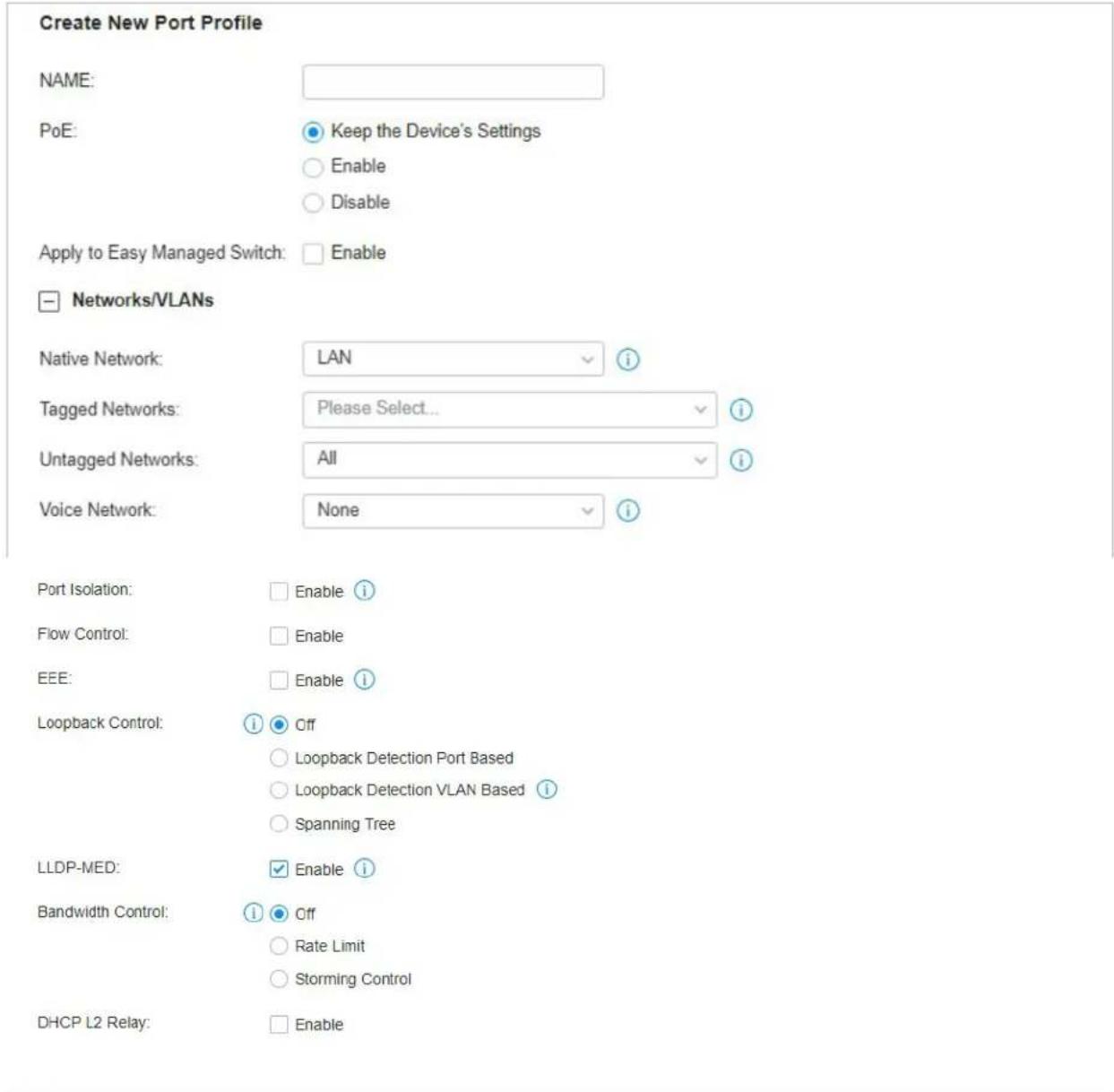
Name Enter a name to identify the port profile.
PoE Select the PoE mode for the ports.
Keep the Device's Settings: PoE keep enabled or disabled according to the switches' settings. By default, the switches enable PoE on all PoE ports.
Enable: Enable PoE on PoE ports.
Disable: Disable PoE on PoE ports.
| Native Network | Select the native network from all networks. The native network determines the Port VLAN Identifier (PVID) for switch ports. When a port receives an untagged frame, the switch inserts a VLAN tag to the frame based on the PVID, and forwards the frame in the native network. Each physical switch port can have multiple networks attached, but only one of them can be native. |
| Tagged Networks Select the Tagged Networks. Frames sent out of a Tagged Network are kept with VLAN tags. Usually networks that connect the switch to network devices like gateways and other switches, or VoIP devices like IP phones should be configured as Tagged Networks. | |
| Untagged Networks | Select the Untagged Networks. Frames that sent out of an Untagged Network are stripped of VLAN tags. Usually networks that connect the switch to endpoint devices like computers should be configured as Untagged Networks. Note that the native network is untagged. |
| Voice Network | Select the network that connects VoIP devices like IP phones as the Voice Network. Switches will prioritize the voice traffic by changing its 802.1p priority. To configure a network as Voice Network, configure it as Tagged Network first, and then enable LLDP-MED. Only tagged networks can be configured as Voice Network, and Voice Network will take effect with LLDP-MED enabled. |
| Port Isolation | Click the checkbox to enable Port Isolation. An isolated port cannot communicate directly with any other isolated ports, while the isolated port can send and receive traffic to non-isolated ports. |
| Flow Control | With this option enabled, when a device gets overloaded it will send a PAUSE frame to notify the peer device to stop sending data for a specified period of time, thus avoiding the packet loss caused by congestion. |
| EEE Click the checkbox to enable EEE (Energy Efficient Ethernet) to allow power reduction. | |
| Loopback Control | Loopback refers to the routing of data streams back to their source in the network. You can disable loopback control for the network or choose a method to prevent loopback happening in your network.Off: Disable loopback control on the port.Loopback Detection Port Based: Loopback Detection Port Based helps detect loops that occur on a specific port. When a loop is detected on a port, the port will be blocked.Loopback Detection VLAN Based: Loopback Detection VLAN Based helps detect loops that occur on a specific VLAN. When a loop is detected on a VLAN, the VLAN will be blocked.Spanning Tree: Select STP (Spanning Tree Protocol) to prevent loops in the network. STP helps block specific ports of the switches to build a loop-free topology and detect topology changes and automatically generate a new loop-free topology.If you want to enable Spanning Tree for the switch, you also need to select the Spanning Tree protocol in the Device Config page. For details, refer to Configure and Monitor Switches. |
LLDP-MED Click the checkbox to enable LLDP-MED (Link Layer Discovery Protocol-Media Endpoint Discovery) for device discovery and auto-configuration of VoIP devices.
| Bandwidth Control | Select the type of Bandwidth Control functions to control the traffic rate and traffic threshold on each port to ensure network performance.Off: Disable Bandwidth Control for the port.Rate Limit: Select Rate limit to limit the ingress/egress traffic rate on each port. With this function, the network bandwidth can be reasonably distributed and utilized.Storming Control: Select Storm Control to allow the switch to monitor broadcast frames, multicast frames and UL-frames (Unknown unicast frames) in the network. If the transmission rate of the frames exceeds the set rate, the frames will be automatically discarded to avoid network broadcast storm. |
| Ingress Rate Limit | When Rate Limit selected, click the checkbox and specify the upper rate limit for receiving packets on the port. |
| Egress Rate Limit | When Rate Limit selected, click the checkbox and specify the upper rate limit for sending packets on the port. |
| Broadcast Threshold | When Storm Control selected, click the checkbox and specify the upper rate limit for receiving broadcast frames. The broadcast traffic exceeding the limit will be processed according to the Action configurations. |
| Multicast Threshold | When Storm Control selected, click the checkbox and specify the upper rate limit for receiving multicast frames. The multicast traffic exceeding the limit will be processed according to the Action configurations. |
| Unknown Unicast Threshold | When Storm Control selected, click the checkbox and specify the upper rate limit for receiving unknown unicast frames. The traffic exceeding the limit will be processed according to the Action configurations.. |
| Action | When Storm Control selected, select the action that the switch will take when the traffic exceeds its corresponding limit. With Drop selected, the port will drop the subsequent frames when the traffic exceeds the limit. With Shutdown selected, the port will be shutdown when the traffic exceeds the limit. |
| DHCP L2 Relay Click the checkbox to enable DHCP L2 Relay for the network. | |
Format Select the format of option 82 sub-option value field.
Normal: The format of sub-option value field is TLV (type-length-value).
Private: The format of sub-option value field is just value.
- Click Save. The new port profile is added to the profile list. You can click ☑ in the ACTION column to edit the port profile. You can click 📋 in the ACTION column to delete the port profile.
| NAME | Easy Managed Switch Enabled | PoE | NATIVE NETWORK | ISOLATION | Bandwidth Control | ACTION |
| All | Keep the Device's Settings | LAN | Off | |||
| Disable | Keep the Device's Settings | None | Off | |||
| LAN | Keep the Device's Settings | LAN | Off | |||
| tp-link | Keep the Device's Settings | LAN | Off |
Create a Network
Create a Port Profile
Assign the Port Profile to the Ports

Note:
By default, there is a port profile named All, which is assigned to all switch ports by default. In the All profile, all networks except the default network (LAN) are configured as Tagged Network, and the native network is the default network (LAN).
- Go to Devices, and click the switch in the devices list to reveal the Properties window. Go to Ports, you can either click ☑ in the Action column to assign the port profile to a single port, or select the desired ports and click Edit Selected on the top to assign the port profile to multiple ports in batch.
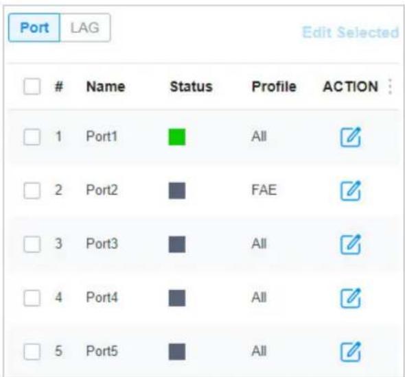
- Select the profile from the drop-down list to assign the port profile to the desired ports of the switch. You can enable profile overrides to customize the settings for the ports, and all the configuration here overrides the port profile. For details, refer to Manage, Configure, and Monitor Devices.
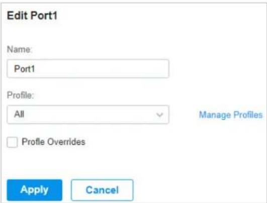
2 Configure Wireless Networks
Wireless networks enable your wireless clients to access the internet. Once you set up a wireless network, your APs typically broadcast the network name (SSID) in the air, through which your wireless clients connect to the wireless network and access the internet.
A WLAN group is a combination of wireless networks. Configure each group so that you can flexibly apply these groups of wireless networks to different APs according to your needs.
After setting up basic wireless networks, you can further configure WLAN Schedule, 802.11 Rate Control, MAC Filter, and other advanced settings.
2.1 Set Up Basic Wireless Networks
Configuration
To create, configure and apply wireless networks, follow these steps:
1) Create a WLAN group.
2) Create Wireless Networks
3) Apply the WLAN group to your APs
Create a WLAN Group Create Wireless Networks Apply the WLAN Group

Note:
The controller provides a default WLAN group. If you simply want to configure wireless networks for the default WLAN group and apply it to all your APs, skip this step.
- Select a site from the drop-down list of Organization. Go to Settings > Wireless Networks to load the following page.

- Select + Create New Group from the drop-down list of WLAN Group to load the following page. Enter a name to identify the WLAN group.
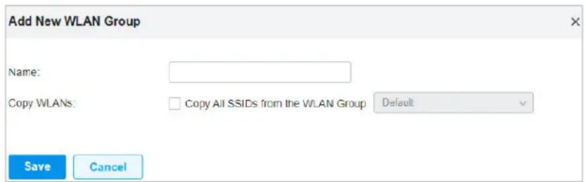
- (Optional) If you want to create a new WLAN group based on an existing one, check Copy All SSIDs from the WLAN Group and select the desired WLAN group. Then you can further configure wireless networks based on current settings.
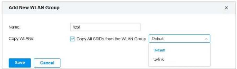
- Click Save. The new WLAN Group is added to the WLAN Group list. You can select a WLAN Group from the list to further create and configure its wireless networks. You can click ☑ to edit the name of the WLAN Group. You can click 🔒 to delete the WLAN Group.

Create a WLAN Group
Create Wireless Networks
Apply the WLAN Group
- Select the WLAN group for which you want to configure wireless networks from the drop-down list of WLAN Group.

- Click + Create New Wireless Network to load the following page. Configure the basic parameters for the network.
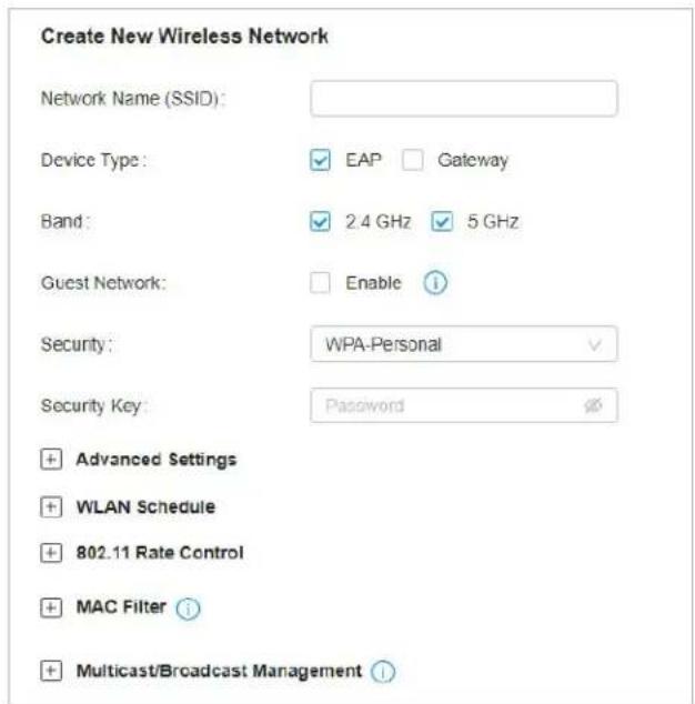
| Network Name (SSID) | Enter the network name (SSID) to identify the wireless network. The users of wireless clients choose to connect to the wireless network according to the SSID, which appears on the WLAN settings page of wireless clients. |
| Device Type Select the type of devices that the wireless network can apply to. | |
| Band Enable the radio band(s) for the wireless network. | |
| Guest Network | With Guest Network enabled, all the clients connecting to the SSID are blocked from reaching any private IP subnet. |
| Security Select the encryption method for the wireless network based on needs. | |
- Select the security strategy for the wireless network.
■ None
With None selected, the hosts can access the wireless network without authentication, which is applicable to lower security requirements.
■ WPA-Personal
With WPA-Personal selected, traffic is encrypted with a Security Key you set,

Security Key Specify a security key to encrypt the traffic.
■ WPA-Enterprise
WPA-Enterprise requires an authentication server to authenticate wireless clients, and probably an accounting server to record the traffic statistics.
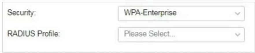
RADIUS Profile
Select a RADIUS Profile, which records the settings of the authentication server and accounting server. You can create a RADIUS Profile by clicking Create New Radius Profile from the drop-down list of RADIUS Profile. For details, refer to Authentication.
Create a WLAN Group Create Wireless Networks Apply the WLAN Group

Note:
The controller provides a default WLAN group. If you simply want to configure wireless networks for the default WLAN group and apply it to all your APs, skip this step.
■ Apply to a Single AP
Go to Devices, select the AP. In the Properties window, go to Config > WLANs, select the WLAN group to apply.
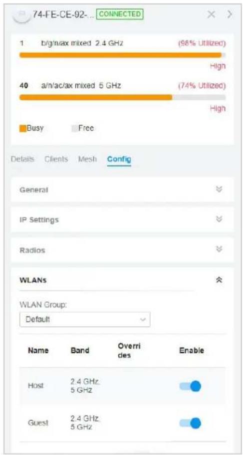
■ Apply to APs in batch
- Go to Devices, select the APs tab, click Batch Action, and then select Batch Config, check the boxes of APs which you want to apply the WLAN group to, and click Done.

- In the Properties window, go to Config > WLANs, select the WLAN group which you want to apply to the AP.
2.2 Advanced Settings
Select a site from the drop-down list of Organization. Go to Settings > Wireless Networks, click ☑ in the ACTION column of the wireless network which you want to configure, and click + Advanced Settings to load the following page. Configure the parameters and click Apply.

Advanced Settings
SSID Broadcast:

Enable
VLAN:

Enable
WPA Mode:
WPA2-PSK/WPA3-SAE / AES

PMF


Mandatory

Capable

Disable
Group Key Update Period

Enable GIK rekeying every

Seconds
(30-86400)
802.11r:

Enable

Client Rate Limit Profile:
Default


SSID Rate Limit Profile:
Default


SSID Broadcast
With SSID Broadcast enabled, APs broadcast the SSID (network name) in the air so that wireless clients can connect to the wireless network, which is identified by the SSID. With SSID Broadcast disabled, users of wireless clients must enter the SSID manually to connect to the wireless network.
VLAN To set a wireless VLAN for the wireless network, enable this option and set a VLAN ID from 1 to 4094.
With this option enabled, traffic in different wireless networks is marked with different VLAN tags according to the configured VLAN IDs. Then the APs work together with the switches which also support 802.1Q VLAN, to distribute the traffic to different VLANs according to the VLAN tags. As a result, wireless clients in different VLANs cannot directly communicate with each other.
WPA Mode If you select WPA-Personal or WPA-Enterprise as the security strategy, you can select the WPA Mode including the version of WPA (WPA-PSK, WPA2-PSK, WPA/WPA2-PSK and WPA-PSK/WPA3-SAE for WPA-Personal, and WPA-Enterprise, WPA2-Enterprise, WPA/WPA2-Enterprise and WPA3-Enterprise for WAP-Enterprise) and the encryption type.
WPA encryption type:
Auto: EAPs automatically determine the encryption type during authentication.
AES: AES stands for Advanced Encryption Standard.
| PMF Protected Management Frames (PMF) provide protection for unicast and multicast management action frames. | |
| Mandatory: Only PMF-capable clients can connect to the network. | |
| Capable: Both types of clients, capable of PMF or not, can connect to the network. Clients capable of PMF will negotiate it with the AP. | |
| Disable: Disables PMF for a network. It is not recommended to use this setting, only in case non-PMF-capable clients experience connection issues with the "Capable" option. | |
| Group Key Update Period | If you select WPA-Personal or WPA-Enterprise as the security strategy, you can specify whether and how often the security key changes. If you want the security key to change periodically, enable GIK rekeying and specify the time period. |
| 802.11r Enable this feature to allow faster roaming when both the AP and client have 802.11r capabilities. Currently 802.11r does not support WPA3 encryption. | |
| Client Rate Limit Profile | Specify the profile to limit the download and upload rates of each client to balance bandwidth usage. |
| You can use the default profile or custom a profile. | |
| SSID Rate Limit Profile | Specify the profile to limit the download and upload rates of each wireless band. Bandwidth is shared among all clients connected to the same wireless band of the same AP. |
| You can use the default profile or custom a profile. | |
| ! Note: This feature requires new firmware updates for APs, and the rate limit settings will only take effect on those APs running firmware that supports the feature. | |
2.3 WLAN Schedule
Overview
WLAN Schedule can turn on or off your wireless network in the specific time period as you desire.
Configuration
Select a site from the drop-down list of Organization. Go to Settings > Wireless Networks, click ☑ in the ACTION column of the wireless network which you want to configure, and click + WLAN Schedule to load the following page. Enable WLAN schedule and configure the parameters. Then click Apply.
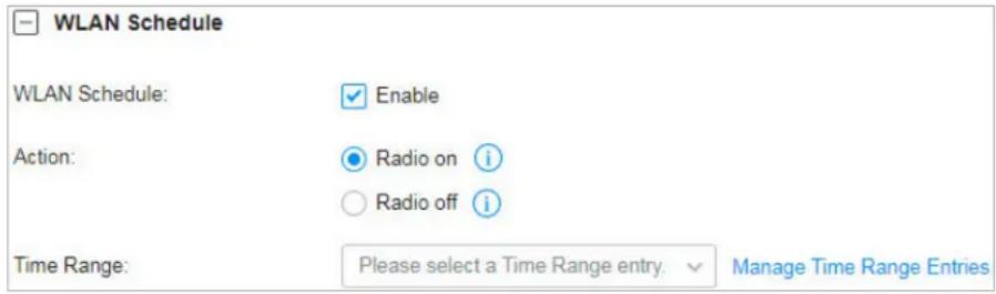
Action Radio On: Turn on your wireless network within the time range you set, and turn it off beyond the time range.
Radio Off: Turn off your wireless network within the time range you set, and turn it on beyond the time range.
Time Range Select the Time Range for the action to take effect. You can create a Time Range entry by clicking + Create New Time Range Entry from the drop-down list of Time Range. For details, refer to Create Profiles.
2.4 802.11 Rate Control
Overview
Note:
802.11 Rate Control is only available for certain devices.
802.11 Rate Control can improve performance for higher-density networks by disabling lower bit rates and only allowing the higher. However, 802.11 Rate Control might make some legacy devices incompatible with your networks, and limit the range of your wireless networks.
Configuration
Select a site from the drop-down list of Organization. Go to Settings > Wireless Networks, click ☑ in the ACTION column of the wireless network which you want to configure, and click + 802.11 Rate Control to load the following page. Select one or multiple bands to enable minimum data rate control according
to your needs, move the slider to determine what bit rates your wireless network allows, and configure the parameters. Then click Apply.
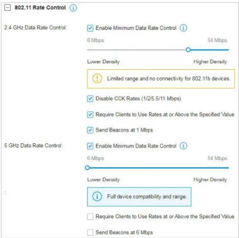
| Disable CCK Rates (1/2/5.5/11 Mbps) | Select whether to disable CCK (Complementary Code Keying), the modulation scheme which works with 802.11b devices. Disable CCK Rates (1/2/5.5/11 Mbps) is only available for 2.4 GHz band. |
| Require Clients to Use Rates at or Above the Specified Value | Select whether or not to require clients to use rates at or above the value specified on the minimum data rate controller slider. |
| Send Beacons at 1 Mbps/6 Mbps | Select whether or not to send Beacons at the minimum rate of 1Mbps for 2.4 GHz band or 6Mbps for 5 GHz band. |
2.5 MAC Filter
Overview
MAC Filter allows or blocks connections from wireless clients of specific MAC addresses.
Configuration
Select a site from the drop-down list of Organization. Go to Settings > Wireless Networks, click ☑ in the ACTION column of the wireless network which you want to configure, and click + MAC Filter to load the following page. Enable MAC Filter and configure the parameters .Then click Apply.

| Policy | Allow List: Allow the connection of the clients whose MAC addresses are in the specified MAC Address List, while blocking others. |
| Deny List: Block the connection of the clients whose MAC address are in the specified MAC Addresses List, while allowing others. | |
| MAC Address List | Select the MAC Group which you want to allow or block according to the policy. You can create new MAC group by clicking + Create New MAC Group from the drop-down list of MAC Address List. For details, refer toCreate Profiles. |
2.6 Multicast/Broadcast Management
Overview
Multicast/Broadcast Management allows packet conversion and multicast filtering.
Configuration
Select a site from the drop-down list of Organization. Go to Settings > Wireless Networks, click ☑ in the ACTION column of the wireless network which you want to configure, and click + Multicast/Broadcast Management to load the following page. Configure the parameters .Then click Apply.
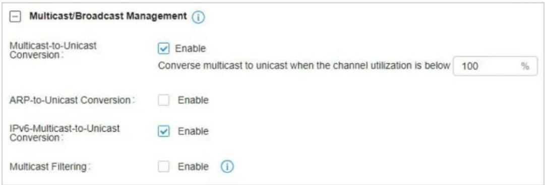
| Multicast-to-Unicast Conversion | When enabled, the controller will convert multicast packets into unicast packets when the channel utilization is below the specified threshold. |
| ARP-to-Unicast Conversion | When enabled, the controller will convert ARP packets into unicast packets. |
| IPv6-Multicast-to-Unicast Conversion | Enable this option if you have high requirements for IPv6 multicast streaming transmission, such as high-definition video on demand. When enabled, the AP maintains IPv6 multicast-to-unicast entries by listening to MLD report packets and MLD leave packets reported by clients. When the AP sends an IPv6 multicast packet to a client, it converts the packet into an IPv6 unicast packet according to the multicast-to-unicast entry, thereby improving the IPv6 transmission efficiency for better wireless experience. |
| Multicast Filtering | When enabled, the controller will filter the multicast packets of the specified protocols. Improper settings may cause network issues. |
3 Network Security
Network Security is a portfolio of features designed to improve the usability and ensure the safety of your network and data. It implements policies and controls on multiple layers of defenses in the network.
3.1 ACL
Overview
ACL (Access Control List) allows a network administrator to create rules to restrict access to network resources. ACL rules filter traffic based on specified criteria such as source IP addresses, destination IP addresses, and port numbers, and determine whether to forward the matched packets. These rules can be applied to specific clients or groups whose traffic passes through the gateway, switches and APs.
The system filters traffic against the rules in the list sequentially. The first match determines whether the packet is accepted or dropped, and other rules are not checked after the first match. Therefore, the order of the rules is critical. By default, the rules are prioritized by their created time. The rule created earlier is checked for a match with higher priority. To reorder the rules, select a rule and drag it to a new position. If no rules match, the device forwards the packet because of an implicit Permit All clause.
The system provides three types of ACL:
■ Gateway ACL
After Gateway ACLs are configured on the controller, they can be applied to the gateway to control traffic which is sourced from LAN ports and forwarded to the WAN ports.
You can set the Network, IP address, port number of a packet as packet-filtering criteria in the rule.
■ Switch ACL
After Switch ACLs are configured on the controller, they can be applied to the switch to control inbound and outbound traffic through switch ports.
You can set the Network, IP address, port number and MAC address of a packet as packet-filtering criteria in the rule.
EAP ACL
After AP ACLs are configured on the controller, they can be applied to the APs to control traffic in wireless networks.
You can set the Network, IP address, port number and SSID of a packet as packet-filtering criteria in the rule.
Configuration
To complete the ACL configuration, follow these steps:
1) Create an ACL with the specified type.
2) Define packet-filtering criteria of the rule, including protocols, source, and destination, and determine whether to forward the matched packets.
■ Configuring Gateway ACL
- Select a site from the drop-down list of Organization. Go to Settings > Network Security > ACL. On Gateway ACL tab, click + Create New Rule to load the following page.
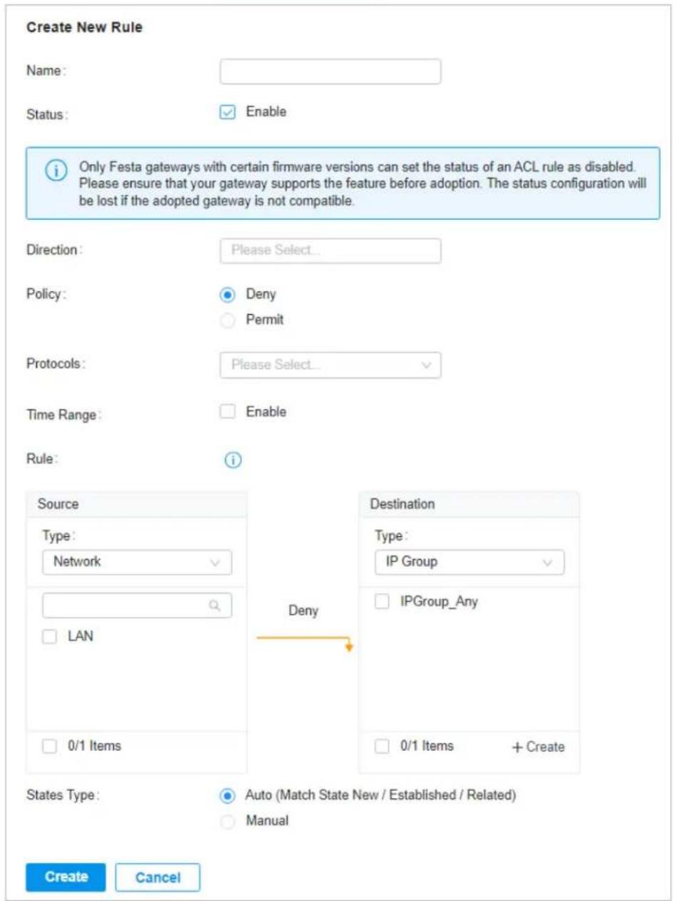
- Define packet-filtering criteria of the rule, including protocols, source, and destination, and determine whether to forward the matched packets. Refer to the following table to configure the required parameters and click Apply.
Name Enter a name to identify the ACL.
Status Click the checkbox to enable the ACL.
Direction Select the direction of ACL application traffic.
LAN->LAN: Control packet forwarding between LAN side devices.
LAN->WAN: Control packet forwarding in the LAN-WAN direction.
Policy Select the action to be taken when a packet matches the rule.
Permit: Forward the matched packet.
Deny: Discard the matched packet.
Protocols Select one or more protocol types to which the rule applies from the drop-down
list. The default is All, indicating that packets of all protocols will be matched. When you select one of TCP and UDP or both of them, you can set the IP address and port number of a packet as packet-filtering criteria in the rule.
Time Range Select the checkbox to enable time-based ACL. You can create a time range or select
an existing time range for the ACL rule to take effect.
From the Source drop-down list, choose one of these options to specify the source of the packets to which this ACL applies:
| Network | Select the network you have created. If no networks have been created, you can select the default network (LAN), or go to Settings > Wired Networks > LAN to create one. The gateway will examine whether the packets are sourced from the selected network. |
| IP Group | Select the IP Group you have created. If no IP Groups have been created, click +Create on this page or go to Settings > Profiles > Groups to create one. The gateway will examine whether the source IP address of the packet is in the IP Group. |
| IP-Port Group | Select the IP-Port Group you have created. If no IP-Port Groups have been created, click +Create on this page or go to Settings > Profiles > Groups to create one. The gateway will examine whether the source IP address and port number of the packet are in the IP-Port Group. |
From the Destination drop-down list, choose one of these options to specify the destination of the packets to which this ACL applies:
| IP Group | Select the IP Group you have created. If no IP Groups have been created, click +Create on this page or go to Settings >Profiles >Groups to create one. The gateway will examine whether the destination IP address of the packet is in the IP Group. |
| IP-Port Group | Select the IP-Port Group you have created. If no IP-Port Groups have been created, click +Create on this page or go to Settings >Profiles >Groups to create one. The gateway will examine whether the destination IP address and port number of the packet are in the IP-Port Group. |
| Gateway Management Page | This option will allow/block LAN network devices to access the gateway management page. |
Set the States Type according to your needs:
States Type Determine the type of stateful ACL rule. It is recommended to use the default Auto type.
Auto (Match Sate New/Established/Related): Match the new, established, and related connection states.
Manual: If selected, you can manually specify the connection states to match.
Match State New: Match the connections of the initial state. For example, a SYN packet arrives in a TCP connection, or the gateway only receives traffic in one direction.
Match State Established: Match the connections that have been established. In other words, the firewall has seen the bidirectional communication of this connection.
Match State Related: Match the associated sub-connections of a main connection, such as a connection to a FTP data channel.
Match State Invalid: Match the invalid sub-connections of a main connection.
■ Configuring Switch ACL
- Select a site from the drop-down list of Organization. Go to Settings > Network Security > ACL. Under the Switch ACL tab, click + Create New Rule to load the following page.
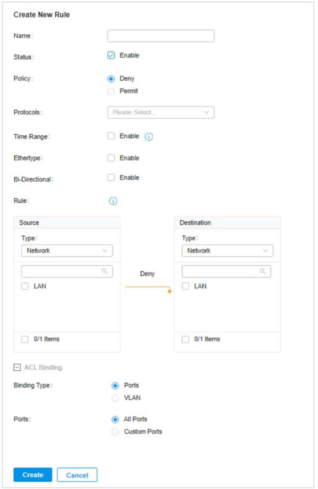
- Define packet-filtering criteria of the rule, including protocols, source, and destination, and determine whether to forward the matched packets. Refer to the following table to configure the required parameters.
| Name Enter a name to identify the ACL. | |
| Status Click the checkbox to enable the ACL. | |
| Policy Select the action to be taken when a packet matches the rule. | |
| Permit: Forward the matched packet. | |
| Deny: Discard the matched packet. | |
| Protocols Select one or more protocol types to which the rule applies from the drop-down list. The default is All, indicating that packets of all protocols will be matched. When you select one of TCP and UDP or both of them, you can set the IP address and port number of a packet as packet-filtering criteria in the rule. | |
| Time Range Select the checkbox to enable time-based ACL. You can create a time range or select an existing time range for the ACL rule to take effect. | |
| Ethertype Click the checkbox if you want the switch to check the ethertype of the packets, and configure the Ethertype based on needs. | |
| Bi-Directional | Click the checkbox to enable the switch to create another symmetric ACL with the name "xxx_reverse", where "xxx" is the name of the current ACL. The two ACLs target at packets with the opposite direction of each other. |
From the Source drop-down list, choose one of these options to specify the source of the packets to which this ACL applies:
| Network | Select the network you have created. If no networks have been created, you can select the default network (LAN), or go to Settings > Wired Networks > LAN to create one. The switch will examine whether the packets are sourced from the selected network. |
| IP Group | Select the IP Group you have created. If no IP Groups have been created, click +Create on this page or go to Settings > Profiles > Groups to create one. The switch will examine whether the source IP address of the packet is in the IP Group. |
| IP-Port Group | Select the IP-Port Group you have created. If no IP-Port Groups have been created, click +Create on this page or go to Settings > Profiles > Groups to create one. The switch will examine whether the source IP address and port number of the packet are in the IP-Port Group. |
| MAC Group Select the MAC Group you have created. If no MAC Groups have been created, click +Create on this page or go to Settings > Profiles > Groups to create one. The switch will examine whether the source MAC address of the packet is in the MAC Group. | |
| IPv6 Group Select the IPv6 Group you have created. If no IPv6 Groups have been created, click +Create on this page or go to Settings > Profiles > Groups to create one. The switch will examine whether the source IP address of the packet is in the IPv6 Group. | |
IPv6-Port Group Select the IPv6-Port Group you have created. If no IPv6-Port Groups have been created, click +Create on this page or go to Settings >Profiles >Groups to create one. The switch will examine whether the source IP address and port number of the packet are in the IPv6-Port Group.
From the Destination drop-down list, choose one of these options to specify the destination of the packets to which this ACL applies:
| Network | Select the network you have created. If no networks have been created, you can select the default network (LAN), or go to Settings > Wired Networks > LAN to create one. The switch will examine whether the packets are forwarded to the selected network. |
| IP Group | Select the IP Group you have created. If no IP Groups have been created, click +Create on this page or go to Settings > Profiles > Groups to create one. The switch will examine whether the destination IP address of the packet is in the IP Group. |
| IP-Port Group | Select the IP-Port Group you have created. If no IP-Port Groups have been created, click +Create on this page or go to Settings > Profiles > Groups to create one. The switch will examine whether the destination IP address and port number of the packet are in the IP-Port Group. |
| MAC Group Select the MAC Group you have created. If no MAC Groups have been created, click +Create on this page or go to Settings > Profiles > Groups to create one. The switch will examine whether the destination MAC address of the packet is in the MAC Group. | |
| IPv6 Group Select the IPv6 Group you have created. If no IPv6 Groups have been created, click +Create on this page or go to Settings > Profiles > Groups to create one. The switch will examine whether the destination IP address of the packet is in the IPv6 Group. | |
| IPv6-Port Group Select the IPv6-Port Group you have created. If no IPv6-Port Groups have been created, click +Create on this page or go to Settings > Profiles > Groups to create one. The switch will examine whether the destination IP address and port number of the packet are in the IPv6-Port Group. | |
- Bind the switch ACL to a switch port or a VLAN and click Apply. Note that a switch ACL takes effect only after it is bound to a port or VLAN.
Binding Type Specify whether to bind the ACL to ports or a VLAN.
Ports: Select All Ports or Custom Ports as the interfaces to be bound with the ACL. With All ports selected, the rule is applied to all ports of the switch. With Custom ports selected, the rule is applied to the selected ports of the switch. Click the ports from the Device List to select the binding ports.

VLAN: Select a VLAN and specify the switches as the interface to be bound with the ACL. If no VLANs have been created, you can select the default VLAN 1 (LAN), or go to Settings > Wired Networks > LAN to create one.
■ Configuring EAP ACL
- Select a site from the drop-down list of Organization. Go to Settings > Network Security > ACL. Under the EAP ACL tab, click + Create New Rule to load the following page.
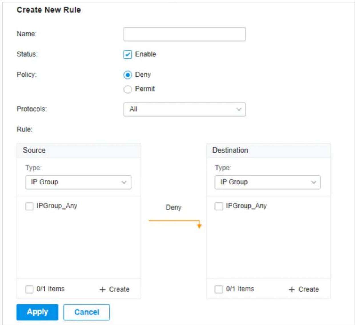
- Define packet-filtering criteria of the rule, including protocols, source, and destination, and determine whether to forward the matched packets. Refer to the following table to configure the required parameters and click Apply.
Name Enter a name to identify the ACL.
Status Click the checkbox to enable the ACL.
Policy Select the action to be taken when a packet matches the rule.
Permit: Forward the matched packet.
Deny: Discard the matched packet.
| Protocols Select one or more protocol types to which the rule applies from the drop-down list. The default is All, indicating that packets of all protocols will be matched. When you select one of TCP and UDP or both of them, you can set the IP address and port number of a packet as packet-filtering criteria in the rule. |
From the Source drop-down list, choose one of these options to specify the source of the packets to which this ACL applies:
| Network | Select the network you have created. If no networks have been created, you can select the default network (LAN), or go to Settings > Wired Networks > LAN to create one. The AP will examine whether the packets are sourced from the selected network. |
| IP Group | Select the IP Group you have created. If no IP Groups have been created, click +Create on this page or go to Settings > Profiles > Groups to create one. The AP will examine whether the source IP address of the packet is in the IP Group. |
| IP-Port Group | Select the IP-Port Group you have created. If no IP-Port Groups have been created, click +Create on this page or go to Settings > Profiles > Groups to create one. The AP will examine whether the source IP address and port number of the packet are in the IP-Port Group. |
| SSID Select the SSID you have created. If no SSIDs have been created, go to Settings > Wireless Networks to create one. The AP will examine whether the SSID of the packet is the SSID selected here. | |
| IPv6 Group Select the IPv6 Group you have created. If no IPv6 Groups have been created, click +Create on this page or go to Settings > Profiles > Groups to create one. The AP will examine whether the source IP address of the packet is in the IPv6 Group. | |
| IPv6-Port Group Select the IPv6-Port Group you have created. If no IPv6-Port Groups have been created, click +Create on this page or go to Settings > Profiles > Groups to create one. The AP will examine whether the source IP address and port number of the packet are in the IPv6-Port Group. | |
From the Destination drop-down list, choose one of these options to specify the destination of the packets to which this ACL applies:
| Network | Select the network you have created. If no networks have been created, you can select the default network (LAN), or go to Settings > Wired Networks > LAN to create one. The AP will examine whether the packets are forwarded to the selected network. |
| IP Group | Select the IP Group you have created. If no IP Groups have been created, click +Create on this page or go to Settings > Profiles > Groups to create one. The AP will examine whether the destination IP address of the packet is in the IP Group. |
| IP-Port Group | Select the IP-Port Group you have created. If no IP-Port Groups have been created, click +Create on this page or go to Settings > Profiles > Groups to create one. The AP will examine whether the destination IP address and port number of the packet are in the IP-Port Group. |
| IPv6 Group Select the IPv6 Group you have created. If no IPv6 Groups have been created, click +Create on this page or go to Settings > Profiles > Groups to create one. The AP will examine whether the destination IP address of the packet is in the IPv6 Group. | |
IPv6-Port Group Select the IPv6-Port Group you have created. If no IPv6-Port Groups have been created, click +Create on this page or go to Settings >Profiles >Groups to create one. The AP will examine whether the destination IP address and port number of the packet are in the IPv6-Port Group.
3.2 URL Filtering
Overview
URL Filtering allows a network administrator to create rules to block or allow certain websites, which protects it from web-based threats, and deny access to malicious websites.
In URL filtering, the system compares the URLs in HTTP, HTTPS and DNS requests against the lists of URLs that are defined in URL Filtering rules, and intercepts the requests that are directed at a blocked URLs. These rules can be applied to specific clients or groups whose traffic passes through the gateway and APs.
The system filters traffic against the rules in the list sequentially. The first match determines whether the packet is accepted or dropped, and other rules are not checked after the first match. Therefore, the order of the rules is critical. By default, the rules are prioritized based on the sequence they are created. The rule created earlier is checked for a match with a higher priority. To reorder the rules, select a rule and drag it to a new position. If no rules match, the device forwards the packet because of an implicit Permit All clause.
Note that URL Filtering rules take effects with a higher priority over ACL rules. That is, the system will process the URL Filtering rule first when the URL Filtering rule and ACL rules are configured at the same time.
Configuration
To complete the URL Filtering configuration, follow these steps:
1) Create a new URL Filtering rule with the specified type.
2) Define filtering criteria of the rule, including source, and URLs, and determine whether to forward the matched packets.
■ Configuring Gateway Rules
- Select a site from the drop-down list of Organization. Go to Settings > Network Security > URL Filtering. Under the Gateway Rules tab, click + Create New Rule to load the following page.
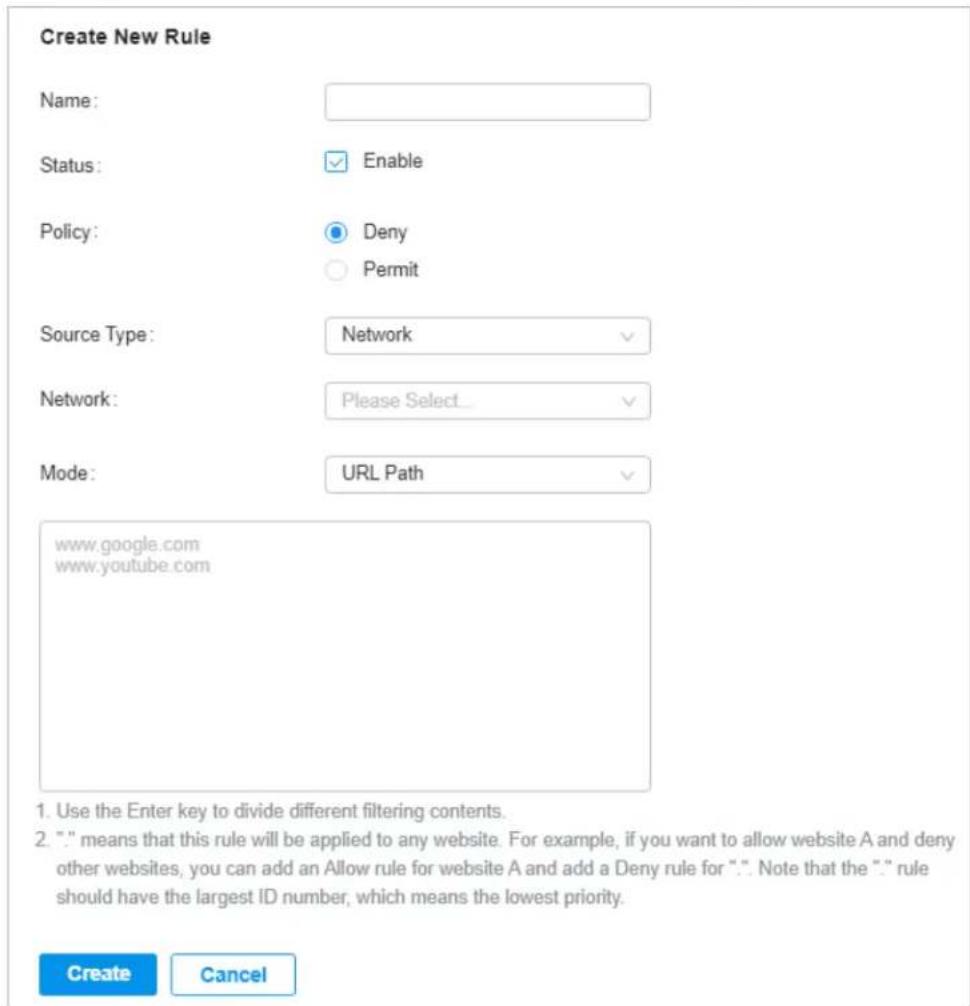
- Define filtering criteria of the rule, including source and URLs, and determine whether to forward the matched packets. Refer to the following table to configure the required parameters and click Apply.
Name Enter a name to identify the URL Filtering rule.
Status Click the checkbox to enable the URL Filtering rule.
Policy Select the action to be taken when a packet matches the rule.
Deny: Discard the matched packet and the clients cannot access the URLs.
Permit: Forward the matched packet and clients can access the URLs.
Source Type Select the source of the packets to which this rule applies.
Network: With Network selected, select the network you have created from the Network drop-down list. If no networks have been created, you can select the default network (LAN), or go to Settings > Wired Networks > LAN to create one. The gateway will filter the packets sourced from the selected network.
IP Group: With IP Group selected, select the IP Group you have created from the IP Group drop-down list. If no IP Groups have been created, click +Create New IP Group on this page or go to Settings > Profiles > Groups to create one. The gateway will examine whether the source IP address of the packet is in the IP Group.
Mode Choose a mode for the filtering content to match the URL.
URL Path: If a URL is the same as any of the entire URL rules specified in the filtering content, the filtering rule will be applied to this URL.
Enter the URL address using up to 128 characters.
URL address should be given in a valid format. The URL which contains a wildcard(*) is supported. One URL with a wildcard(*) can match multiple subdomains. For example, with *.tp-link.com specified, community.tp-link.com will be matched.
Keywords: If a URL contains any of the keywords specified in the filtering content, the filtering rule will be applied to this URL.
■ Configuring EAP Rules
- Select a site from the drop-down list of Organization. Go to Settings > Network Security > URL Filtering. On EAP Rules tab, click + Create New Rule to load the following page.
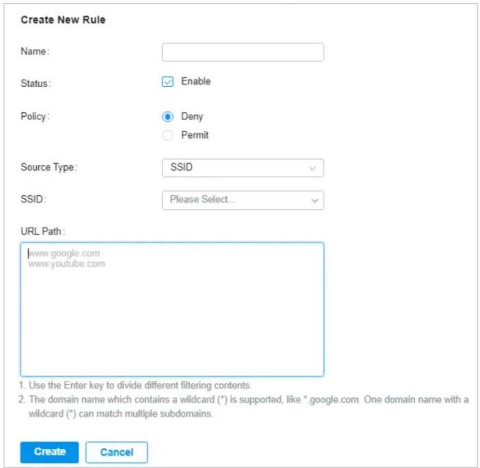
- Define filtering criteria of the rule, including source and URLs, and determine whether to forward the matched packets. Refer to the following table to configure the required parameters and click Apply.
Name Enter a name to identify the URL Filtering rule.
Status Click the checkbox to enable the URL Filtering rule.
Policy Select the action to be taken when a packet matches the rule.
Deny: Discard the matched packet and the clients cannot access the URLs.
Permit: Forward the matched packet and clients can access the URLs.
Source Type Select the SSID of the packets to which this rule applies.
URL Path Enter the URL address using up to 128 characters.
URL address should be given in a valid format. The URL which contains a wildcard(*) is supported. One URL with a wildcard(*) can match multiple subdomains. For example, with *.tp-link.com specified, community.tp-link.com will be matched.

4 Transmission
Transmission helps you control network traffic in multiple ways. You can add policies and rules to control transmission routes and limit the session and bandwidth.
4.1 Routing
Overview
■ Static Route
Network traffic is oriented to a specific destination, and Static Route designates the next hop or interface where to forward the traffic.
■ Policy Routing
Policy Routing designates which WAN port the gateway uses to forward the traffic based on the source, the destination, and the protocol of the traffic.
Configuration
■ Static Route
- Go to Setting > Transmission > Routing > Static Route. Click + Create New Route to load the following page and configure the parameters.
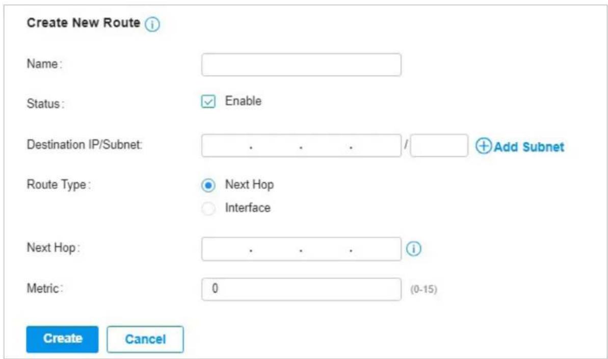
Name Enter the name to identify the Static Route entry.
Status Enable or disable the Static Route entry.
| Destination IP/Subnet | Destination IP/Subnet identifies the network traffic which the Static Route entry controls. Specify the destination of the network traffic in the format of 192.168.0.1/24. You can click + Add Subnet to specify multiple Destination IP/Subnets and click 📋 to delete them. |
| Route Type Next Hop: With Next Hop selected, your devices forward the corresponding network traffic to a specific IP address. You need to specify the IP address as Next Hop. | |
| Metric Define the priority of the Static Route entry. A smaller value means a higher priority. If multiple entries match the Destination IP/Subnet of the traffic, the entry of higher priority takes precedence. In general, you can simply keep the default value. | |
- Click Create. The new Static Route entry is added to the table. You can click ☑ to edit the entry. You can click 🔒 to delete the entry.

■ Policy Routing
- Go to Setting > Transmission > Routing > Policy Routing. Click + Create New Routing to load the following page and configure the parameters.
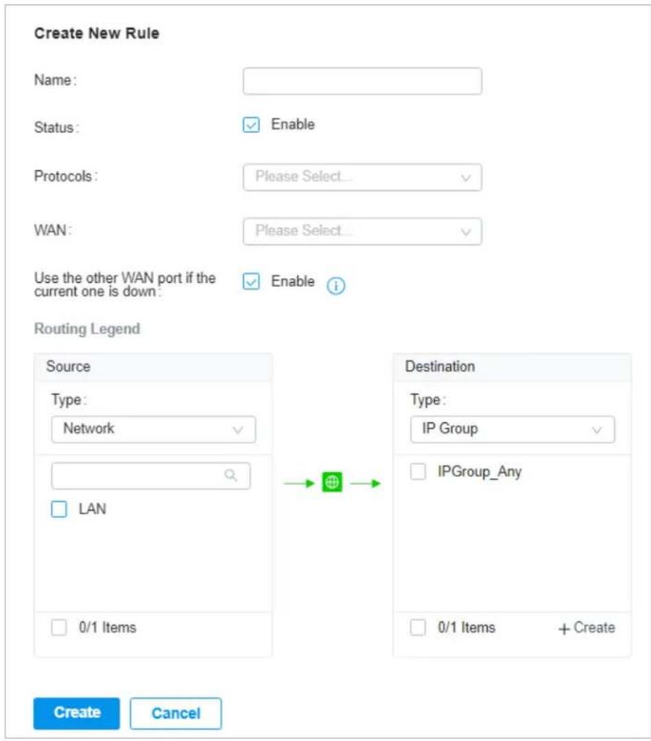
Name Enter the name to identify the Policy Routing entry.
Status Enable or disable the Policy Routing entry.
Protocols Select the protocols of the traffic which the Policy Routing entry controls. The Policy Routing entry takes effect only when the traffic matches the criteria of the entry including the protocols.
WAN Select the WAN port to forward the traffic through. If you want to forward the traffic through the other WAN port when the current WAN is down, enable Use the other WAN port if the current one is down.
Routing Legend The Policy Routing entry takes effect only when the traffic using specified protocols matches the source and destination which are specified in the Routing Legend.
Select the type of the traffic source and destination.
Network: Select the LAN Interfaces for the traffic source or destination.
IP Group: Select the IP Group for the traffic source or destination. You can click + Create to create a new IP Group.
IP-Port Group: Select the IP-Port Group for the traffic source or destination. You can click + Create to create a new IP-Port Group.
- Click Create. The new Policy Routing entry is added to the table. You can click ☑ to edit the entry. You can click 🔒 to delete the entry.

4.2 Bandwidth Control
Overview
Bandwidth Control optimizes network performance by limiting the bandwidth of specific sources.
Configuration
- Go to Setting > Transmission > Bandwidth Control. In Bandwidth Control, enable Bandwidth Control globally and configure the parameters. Then click Apply.
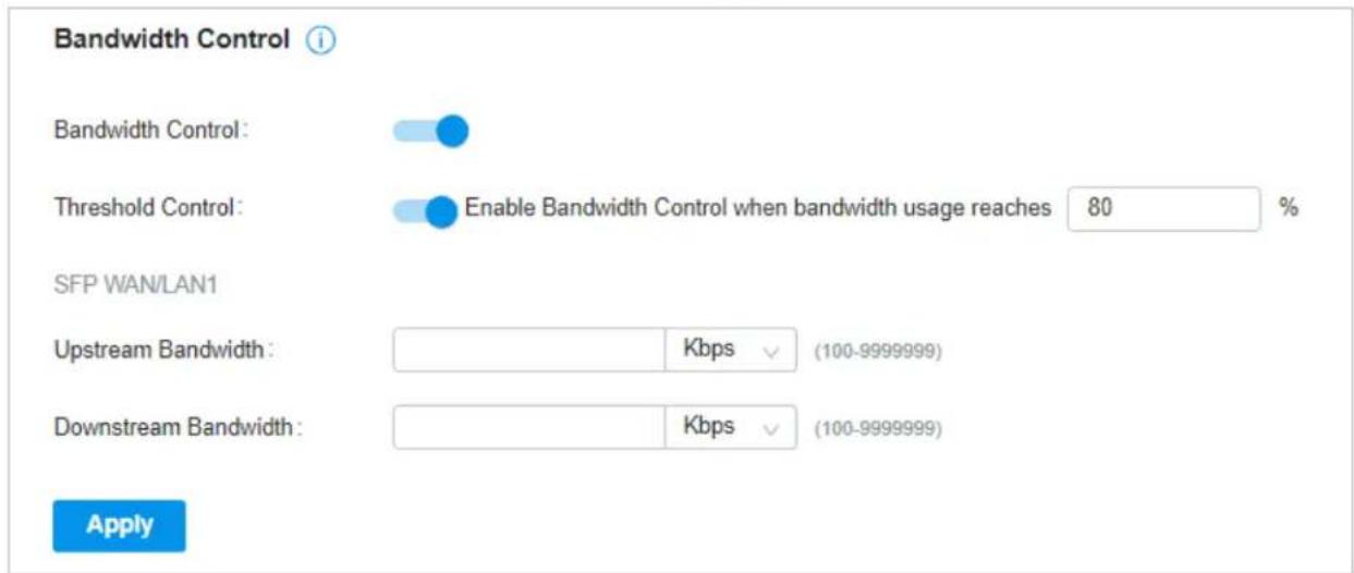
Threshold Control
With Threshold Control enabled, Bandwidth Control takes effect only when total bandwidth usage reaches the specified percentage. You need to specify the total Upstream Bandwidth and Downstream Bandwidth of the WAN ports.
- In Bandwidth Control Rule List, click + Create New Rule to load the following page and configure the parameters.
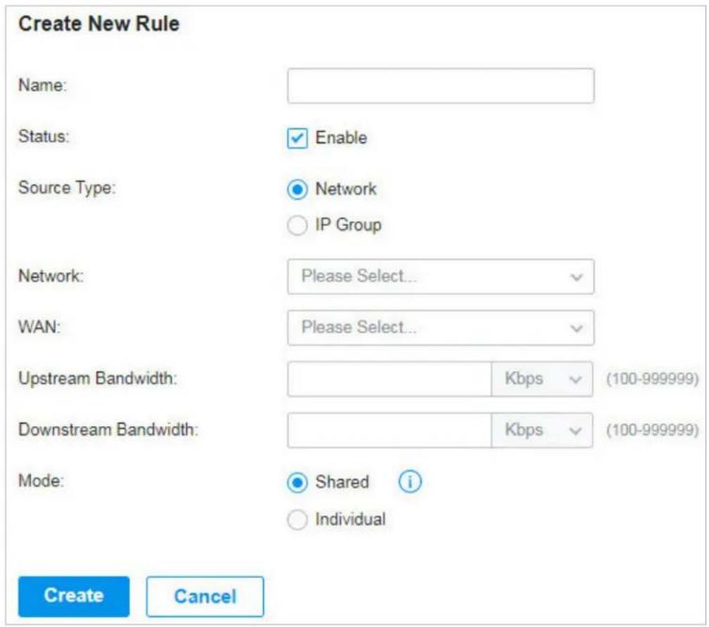
Name Enter the name to identify the Bandwidth Control rule.
Status Enable or disable the Bandwidth Control rule.
Source Type
Network: Limit the maximum bandwidth of specific LAN networks. With this option selected, choose the networks, which you can create or customize in Wired Networks > LAN. For detailed configuration of networks, refer to Configure LAN Networks.
IP Group: Limit the maximum bandwidth of specific IP Groups. With this option selected, choose the IP Groups. To create IP groups, click + Create New IP Group from the drop-down list or go to Profiles > Groups. To edit or delete the existing groups, go to Profiles > Groups. For detailed configuration of IP groups, refer to Create Profiles.
WAN Select the WAN port which the rule applies to.
Upstream Bandwidth
Specify the limit of Upstream Bandwidth, which the specific local hosts use to transmit traffic to the internet through the gateway.
Downstream Bandwidth
Specify the limit of Downstream Bandwidth, which the specific local hosts use to receive traffic from the internet through the gateway.
Mode Specify the bandwidth control mode for the specific local hosts.
Shared: The total bandwidth for all the local hosts is equal to the specified values.
Individual: The bandwidth for each local host is equal to the specified values.
- Click Create. The new Bandwidth Control rule is added to the list. You can click ☑ to edit the rule. You can click 🔒 to delete the rule.

4.3 Port Forwarding
Overview
You can configure Port Forwarding to allow internet users to access local hosts or use network services which are deployed in the LAN.
Port Forwarding helps establish network connections between a host on the internet and the other in the LAN by letting the traffic pass through the specific port of the gateway. Without Port Forwarding, hosts in the LAN are typically inaccessible from the internet for the sake of security.
Configuration
- Go to Setting > Transmission > Port Forwarding. Click + Create New Rule to load the following page and configure the parameters.
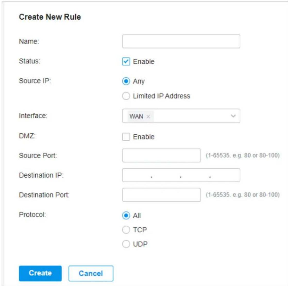
Name Enter the name to identify the Port Forwarding rule.
Status Enable or disable the Port Forwarding rule.
Source IP
Any: The rule applies to traffic from any source IP address.
Limited IP Address: The rule only applies to traffic from specific IP addresses. With this option selected, specify the IP addresses and subnets according to your needs. You can click + Add Subnet to specify multiple entries or click 🔒 to delete them.
Interface Select the interface which the rule applies to. Traffic which is received through the interface is forwarded according to the rule.
| DMZ | With DMZ enabled, all the traffic is forwarded to the Destination IP in the LAN, port to port. You need to specify the Destination IP.With DMZ disabled, only the traffic which matches the Source Port and the Protocol is forwarded. The traffic is forwarded to the Destination Port of the Destination IP in the LAN. You need to specify the Source Port, Destination IP, Destination Port, and Protocol. |
| Source Port | The gateway uses the Source Port to receive the traffic from the internet. Only the traffic which matches the Source Port and the Protocol is forwarded. |
| Destination IP | The traffic is forwarded to the host of the Destination IP in the LAN. |
| Destination Port | The traffic is forwarded to the Destination Port of the host in the LAN. |
| Protocol Network traffic is transmitted using either TCP or UDP protocol. Only the traffic which matches the Source Port and the Protocol is forwarded.If you want both TCP traffic and UDP traffic to be forwarded, select All. | |
- Click Create. The new Port Forwarding entry is added to the table. You can click ☑ to edit the entry. You can click 🔒 to delete the entry.

5 Configure VPN
VPN (Virtual Private Network) provides a means for secure communication between remote computers across a public wide area network (WAN), such as the internet. The gateways supports various types of VPN.
5.1 VPN
Overview
VPN (Virtual Private Network) gives remote LANs or users secure access to LAN resources over a public network such as the internet. Virtual indicates the VPN connection is based on the logical end-to-end connection instead of the physical end-to-end connection. Private indicates users can establish the VPN connection according to their requirements and only specific users are allowed to use the VPN connection.
The core of VPN connection is to realize tunnel communication, which fulfills the task of data encapsulation, data transmission and data decompression via the tunneling protocol. The gateway supports common tunneling protocols that a VPN uses to keep the data secure:
IPsec
IPsec (IP Security) can provide security services such as data confidentiality, data integrity and data authentication at the IP layer. IPsec uses IKE (Internet Key Exchange) to handle negotiation of protocols and algorithms based on the user-specified policy, and to generate the encryption and authentication keys to be used by IPsec. IPsec can be used to protect one or more paths between a pair of hosts, between a pair of security gateways, or between a security gateway and a host.
■ PPTP
PPTP (Point-to-Point Tunneling Protocol) is a network protocol that enables the secure transfer of data from a remote client to a private enterprise server by creating a VPN across TCP/IP-based data networks. PPTP uses the username and password to validate users.
L2TP
L2TP (Layer 2 Tunneling Protocol) provides a way for a dialup user to make a virtual Point-to-Point Protocol (PPP) connection to an L2TP network server (LNS), which can be a security gateway. L2TP sends PPP frames through a tunnel between an L2TP access concentrator (LAC) and the LNS. Because of the lack of confidentiality inherent in the L2TP protocol, it is often implemented along with IPsec. L2TP uses the username and password to validate users.
OpenVPN
OpenVPN uses OpenSSL for encryption of UDP and TCP for traffic transmission. OpenVPN uses a client-server connection to provide secure communications between a server and a remote client over the internet. One of the most important steps in setting up OpenVPN is obtaining a certificate which is used for authentication. The SDN controller supports generating the certificate which can be downloaded as a file on your computer. With the certificate imported, the remote clients are checked out by the certificate and granted access to the LAN resources.
There are many variations of virtual private networks, with the majority based on two main models:
■ Site-to-Site VPN
A Site-to-Site VPN creates a connection between two networks at different geographic locations. Typically, headquarters set up Site-to-Site VPN with the subsidiary to provide the branch office with access to the headquarters' network.
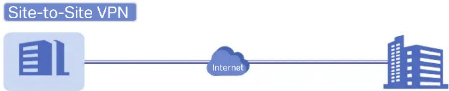
flowchart
graph LR
    A["Site-to-Site VPN"] --> B["Internet"]
    B --> C["Building 1"]
    B --> D["Building 2"]
Branch Office Headquarters
The gateway supports two types of Site-to-Site VPNs:
- Auto IPsec
The controller automatically creates an IPsec VPN tunnel between two sites on the same controller. The VPN connection is bidirectional. That is, creating an Auto IPsec VPN from site A to site B also provides connectivity from site B to site A, and nothing is needed to be configured on site B.
- Manual IPsec
You create an IPsec VPN tunnel between two peer gateways over internet manually, from a local gateway to a remote gateway that supports IPsec. The gateway on this site is the local peer gateway.
■ Client-to-Site VPN
A Client-to-Site VPN creates a connection to the LAN from a remote host. It is useful for teleworkers and business travelers to access their central LAN from a remote location without compromising privacy and security.
The first step to build a Client-to-Site VPN connection is to determine the role of the gateways and which VPN tunneling protocol to use:
- VPN Server
The gateway on the central LAN works as a VPN server to provide a remote host with access to the local network. The gateway which functions as a VPN server can use L2TP, PPTP, IPsec, or OpenVPN as the tunneling protocol.
- VPN Client
Either the remote user's gateway or the remote user's laptop or PC works as the VPN client.
When the remote user's gateway works as the VPN client, the gateway helps create VPN tunnels between its connected hosts and the VPN server. The gateway which functions as a VPN client can use L2TP, PPTP, or OpenVPN as the tunneling protocol.
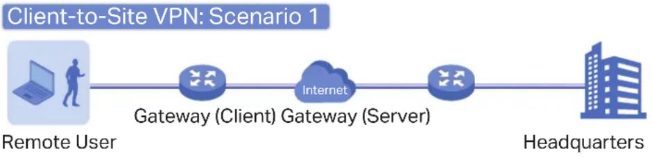
flowchart
graph LR
    A["Remote User"] --> B["Gateway (Client) Gateway (Server)"]
    B --> C["Internet"]
    C --> D["Headquarters"]
When the remote user's laptop or PC works as the VPN client, the laptop or PC uses a VPN client software program to create VPN tunnels between itself and the VPN server. The VPN client software program can use L2TP, PPTP, IPsec, or OpenVPN as the tunneling protocol.
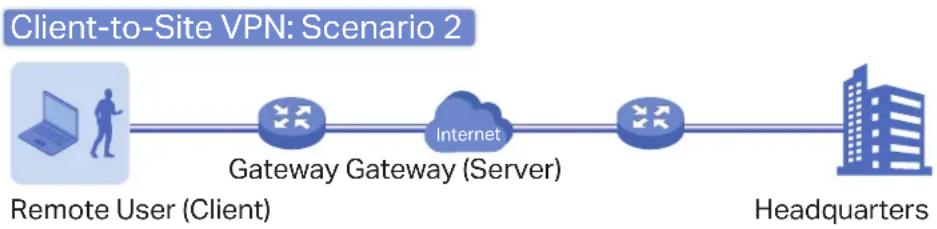
flowchart
graph LR
    A["Remote User (Client)"] --> B["Gateway Gateway (Server)"]
    B --> C["Internet"]
    C --> D["Headquarters"]

Note:
In scenario 1, you need to configure VPN client and VPN server separately on the gateways, while remote hosts can access the local networks without running VPN client software.
In scenario 2, you need to configure VPN server on the gateway, and then configure the VPN client software program on the remote user's laptop or PC, while the remote user's gateway doesn't need any VPN configuration.
Here is the infographic to provide a quick overview of VPN solutions.

Create a VPN Policy

Select the purpose of the VPN
Site-to-Site VPN

flowchart
graph LR
    A["Building"] --> B["Internet"]
    B --> C["Building"]
Branch Office Headquarters
Auto IPsec VPN
The controller automatically creates an IPsec VPN tunnel between two sites on the same controller.
Manual IPsec VPN
You manually create an IPsec VPN tunnel between two peer gateways over internet, from a local gateway to a remote gateway that supports IPsec.
Client-to-Site VPN

flowchart
graph LR
    A["Client"] --> B["Gateway (Client)"]
    B --> C["Gateway (Server)"]
    C --> D["Internet"]
    D --> E["Client"]
    style A fill:#f9f,stroke:#333
    style E fill:#bbf,stroke:#333
Remote User
Headquarters

flowchart
graph LR
    A["Laptop"] --> B["Gateway"]
    B --> C["Internet"]
    C --> D["Gateway (Server)"]
    D --> E["Building"]
Remote User (Client)
Headquarters

Select the role of the gateway and VPN tunneling protocol
VPN Server
L2TP
VPN Client
PPTP
L2TP
IPsec
PPTP
OpenVPN
IPsec (Only for VPN client software)
OpenVPN
Configuration
To complete the VPN configuration, follow these steps:
1) Create a new VPN policy and select the purpose of the VPN according to your needs. Select Site-to-Site if you want the network connected to another. Select Client-to-Site if you want some hosts connected to the network.
2) Select the VPN tunneling protocol and configure the VPN policy based on the protocol.
■ Configuring Site-to-Site VPN
The gateway supports two types of Site-to-Site VPNs: Auto IPsec and Manual IPsec.
- Configuring Auto IPsec VPN
- Select a site from the drop-down list of Organization. Go to Settings > VPN. Click + Create New VPN Policy to load the following page.
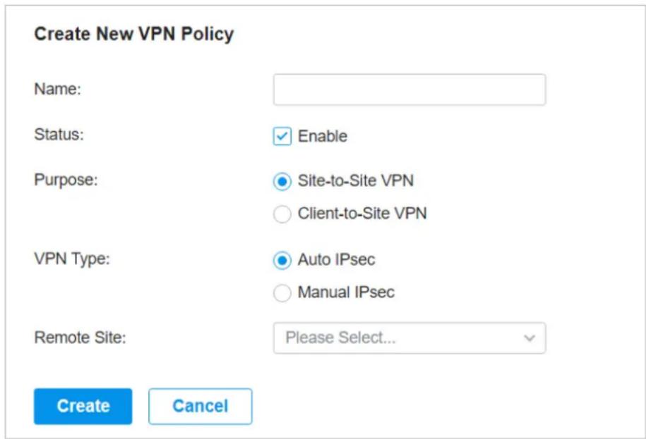
- Enter a name to identify the VPN policy and select the purpose as Site-to-Site VPN. Refer to the following table to configure the required parameters and click Create.
Name Enter a name to identify the VPN policy.
Status Click the checkbox to enable the VPN policy.
Purpose Select the purpose for the VPN as Site-to-Site VPN.
VPN Type
Select the VPN type as Auto IPsec. With Auto IPsec, the controller automatically creates an IPsec VPN tunnel between two sites on the same controller. The VPN connection is bidirectional. That is, creating an Auto IPsec VPN from site A to site B also provides connectivity from site B to site A, and nothing is needed to be configured on site B.
Remote Site Select the site on the other end of the Auto IPsec VPN tunnel. Make sure that the selected remote site has an online gateway within the same controller.
- Configuring Manual IPsec VPN
- Select a site from the drop-down list of Organization. Go to Settings > VPN. Click + Create New VPN Policy to load the following page.
Create New VPN Policy
Name:

Status:
Enable
Purpose:
Site-to-Site VPN
○ Client-to-Site VPN
VPN Type:
○ Auto IPsec
Manual IPsec
Remote Gateway:

Remote Subnets:


Add Subnet
Local Network Type:
Network
○ Custom IP
Local Networks:
All

Pre-Shared Key:

WAN:
Please Select...
V

Advanced Settings
Create
Cancel
- Enter a name to identify the VPN policy and select the purpose as Site-to-Site VPN. Refer to the following table to configure the basic parameters and click Create.
Name Enter a name to identify the VPN policy.
Status Click the checkbox to enable the VPN policy.
| Purpose Select the purpose for the VPN as Site-to-Site VPN. | |
| VPN Type Select the VPN type as Manual IPsec. | |
| Remote Gateway Enter an IP address or a domain name as the gateway on the remote peer of the VPN tunnel. | |
| Remote Subnets Enter the IP address range of LAN on the remote peer of the VPN tunnel. Remote subnets should not be in the same network segment as the local LAN. You can click + Add Subnet to specify multiple entries or click 📄 to delete them. | |
| Local Network Type | Specify whether to apply the VPN policy to specific local networks or IP addresses. |
| Network: The VPN policy will be only applied to the selected local networks. | |
| Custom IP: The VPN policy will be only applied to the specified IP addresses. | |
| Local Networks | When selecting Network as the Local Network Type, specify the local networks of the VPN tunnel. |
| When selecting Custom IP as the Local Network Type, specify the IP addresses of the VPN tunnel. You can click + Add New to specify multiple entries or click 📄 to delete them. | |
| Pre-Shared Key | Enter the pre-shared key(PSK). Both peer gateways must use the same pre-shared secret key for authentication. |
| A pre-shared key is a string of characters that is used as an authentication key. Both peer gateways create a hash value based on the same pre-shared key and other information. The hash values are then exchanged and verified to authenticate the other party. | |
| The pre-shared keys should be long and random for security. Short or predictable pre-shared keys can be easily broken in brute-force attacks. To maintain a high level of security, administrators are recommended to update the pre-shared key periodically. | |
| WAN Select the WAN port on which the IPsec VPN tunnel is established. | |
3. Click Advanced Settings to load the following page.
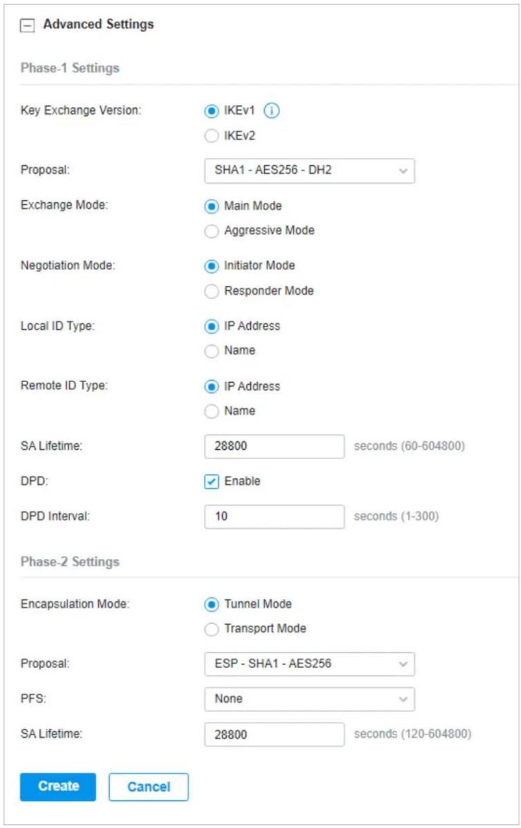
Advanced settings include Phase-1 settings and Phase-2 settings. Phase-1 is used to set up a secure encrypted channel which the two peers can negotiate Phase-2, and then establish the IKE Security Associations (IKE SA). Phase-2 is used to negotiate about a set of parameters that
define what traffic can go through the VPN, and how to encrypt and authenticate the traffic, then establish the IPsec Security Associations (IPsec SA).
Refer to the following table to complete the configurations according to your actual needs and click Create.
For Phase-1 Settings:
| Phase-1 Settings | The IKE version you select determines the available Phase-1 settings and defines the negotiation process. Both VPN gateways must be configured to use the same IKE version and Phase-1 settings. |
| Key Exchange Version | Select the version of Internet Key Exchange (IKE) protocol which is used to set up security associations for IPsec. Both IKEv1 and IKEv2 are supported with gateways, but IKEv1 is available only when the VPN policy is applied to a single Remote Subnet and a single Local Network.Note that both peer gateways must be configured to use the same IKE version. |
| Proposal Specify the proposal for IKE negotiation phase-1. An IKE proposal lists the encryption algorithm, authentication algorithm and Diffie-Hellman (DH) groups to be negotiated with the remote IPsec peer.Authentication algorithms verify the data integrity and authenticity of a message.Encryption algorithms protect the data from being read by a third-party.Diffie-Hellman (DH) groups determine the strength of the key used in the key exchange process.Note that both peer gateways must be configured to use the same Proposal. | |
| Exchange Mode Specify the IKE Exchange Mode as Main Mode or Aggressive Mode when IKEv1 is selected.Main Mode: This mode provides identity protection and exchanges more information, which applies to scenarios with higher requirements for identity protection.Aggressive Mode: This mode establishes a faster connection but with lower security, which applies to scenarios with lower requirements for identity protection. | |
| Negotiation Mode Specify the IKE Negotiation Mode as Initiator Mode or Responder Mode.Initiator Mode: This mode means that the local device initiates a connection to the peer.Responder Mode: This mode means that the local device waits for the connection request initiated by the peer. | |
| Local ID Type | Specify the type of Local ID which indicates the authentication identifier sent to the peer for IKE negotiation. |
| IP Address: Select IP Address to use the IP address for authentication. | |
| Name: Select Name, and then enter the name in the Local ID field to use the name as the ID for authentication. | |
| Note that the type and value of Local ID should be the same as Remote ID given for the remote peer of the VPN tunnel. | |
| Local ID When the Local ID Type is configured as Name, enter a name for the local device as the ID in IKE negotiation. The name should be in the format of FQDN (Fully Qualified Domain Name). | |
| Remote ID Type Specify the type of Remote ID which indicates the authentication identifier received from the peer for IKE negotiation. | |
| Remote ID When the Remote ID Type is configured as Name, enter a name of the remote peer as the ID in IKE negotiation. The name should be in the format of FQDN (Fully Qualified Domain Name). | |
| SA Lifetime | Specify ISAKMP SA (Security Association) Lifetime in IKE negotiation. If the SA lifetime expired, the related ISAKMP SA will be deleted. |
| DPD Check the box to enable DPD (Dead Peer Detect) function. If enabled, the IKE endpoint can send a DPD request to the peer to inspect whether the IKE peer is alive. | |
| DPD Interval | Specify the interval between sending DPD requests with DPD enabled. If the IKE endpoint receives a response from the peer during this interval, it considers the peer alive. If the IKE endpoint does not receive a response during the interval, it considers the peer dead and deletes the SA. |
For Phase-2 Settings:
| Phase-2 Settings | The purpose of Phase 2 negotiations is to establish the Phase-2 SA (also called the IPsec SA). The IPsec SA is a set of traffic specifications that tell the device what traffic to send over the VPN, and how to encrypt and authenticate that traffic. |
| Encapsulation Mode Specify the Encapsulation Mode as Tunnel Mode or Transport Mode. When both ends of the tunnel are hosts, either mode can be chosen. When at least one of the endpoints of a tunnel is a security gateway, such as a gateway or firewall, Tunnel Mode is recommended to ensure safety. | |
| Proposal Specify the proposal for IKE negotiation phase-2. An IPsec proposal lists the encryption algorithm, authentication algorithm and protocol to be negotiated with the remote IPsec peer.Note that both peer gateways must be configured to use the same Proposal. | |
| PFS Select the DH group to enable PFS (Perfect Forward Security) for IKE mode, then the key generated in phase-2 will be irrelevant with the key in phase-1, which enhance the network security. With None selected, it means PFS is disabled and the key in phase-2 will be generated based on the key in phase-1. |
| SA Lifetime Specify IPsec SA (Security Association) Lifetime in IKE negotiation. If the SA lifetime expired, the related IPsec SA will be deleted. |
■ Configuring Client-to-Site VPN
The gateway supports seven types of client-to-Site VPNs depending on the role of your gateway and the protocol that you used:
| Configuring the gateway as a VPN server using L2TP |
| Configuring the gateway as a VPN server using PPTP |
| Configuring the gateway as a VPN server using IPsec |
| Configuring the gateway as a VPN server using OpenVPN |
| Configuring the gateway as a VPN client using L2TP |
| Configuring the gateway as a VPN client using PPTP |
| Configuring the gateway as a VPN client using OpenVPN |
- Configuring the gateway as a VPN server using L2TP
- Select a site from the drop-down list of Organization. Go to Settings > VPN. Click + Create New VPN Policy to load the following page.
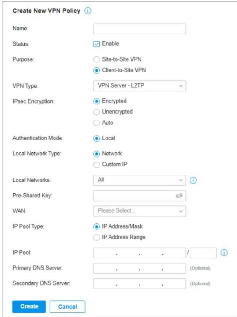
- Enter a name to identify the VPN policy and select the purpose as Client-to-Site VPN. Refer to the following table to configure the required parameters and click Create.
Name Enter a name to identify the VPN policy.
Status Click the checkbox to enable the VPN policy.
Purpose Select the purpose for the VPN as Client-to-Site VPN.
VPN Type Select the VPN type as VPN Server - L2TP.
IPsec Encryption Specify whether to enable the encryption for the tunnel.
Encrypted: Select Encrypted to encrypt the L2TP tunnel by IPsec (L2TP over IPsec). With Encrypted selected, enter the Pre-shared Key for IKE authentication. VPN server and VPN client must use the same pre-shared secret key for authentication.
Unencrypted: With Unencrypted selected, the L2TP tunnel will not be encrypted by IPsec.
Auto: With Auto selected, the L2TP server will determine whether to encrypt the tunnel according to the client's encryption settings. And enter the Pre-shared Key for IKE authentication. VPN server and VPN client must use the same pre-shared secret key for authentication.
Authentication Mode The authentication mode is Local by default.
Local Network Type Specify whether to apply the VPN policy to specific local networks or IP addresses.
Network: The VPN policy will be only applied to the selected local networks.
Custom IP: The VPN policy will be only applied to the specified IP addresses.
Local Networks When selecting Network as the Local Network Type, specify the local networks of the VPN tunnel.
When selecting Custom IP as the Local Network Type, specify the IP addresses of the VPN tunnel. You can click + Add New to specify multiple entries or click 📄 to delete them.
Pre-shared Key Enter the pre-shared secret key when IPsec Encryption is selected as Encrypted and Auto. Both peer gateways must use the same pre-shared secret key for authentication.
WAN Select the WAN port on which the L2TP VPN tunnel is established. Each WAN port supports only one L2TP VPN tunnel when the gateway works as a L2TP server.
IP Pool Type Specify the format of the IP pool.
IP Pool If you selected IP Address/Mask type, enter the IP address and subnet mask to decide the range of the VPN IP pool. If you select IP Address Range type, enter the start and end IP addresses of the VPN IP pool.
Primary DNS Server (Optional) Enter the IP address of the primary DNS server provided by your ISP.
Secondary DNS Server (Optional) Enter the IP address of the secondary DNS server, which provides redundancy in case the primary DNS server goes down.
- Add the VPN users account to validate remote hosts. To create VPN users, refer to VPN User.
- Configuring the gateway as a VPN server using PPTP
- Select a site from the drop-down list of Organization. Go to Settings > VPN. Click + Create New VPN Policy to load the following page.
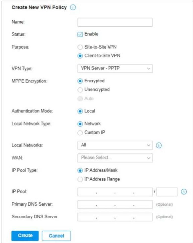
- Enter a name to identify the VPN policy and select the purpose as Client-to-Site VPN. Refer to the following table to configure the required parameters and click Create.
| Name Enter a name to identify the VPN policy. | |
| Status Click the checkbox to enable the VPN policy. | |
| Purpose Select the purpose for the VPN as Client-to-Site VPN. | |
| VPN Type Select the VPN type as VPN Server - PPTP. | |
| MPPE Encryption Specify whether to enable MPPE (Microsoft Point-to-Point Encryption) for the tunnel.Encrypted: With Encrypted selected, the PPTP tunnel will be encrypted by MPPE.Unencrypted: With Unencrypted selected, the PPTP tunnel will be not encrypted by MPPE. | |
| Authentication Mode The authentication mode is Local by default. | |
| Local Network Type | Specify whether to apply the VPN policy to specific local networks or IP addresses. |
| Network: The VPN policy will be only applied to the selected local networks. | |
| Custom IP: The VPN policy will be only applied to the specified IP addresses. | |
| Local Networks | When selecting Network as the Local Network Type, specify the local networks of the VPN tunnel. |
| When selecting Custom IP as the Local Network Type, specify the IP addresses of the VPN tunnel. You can click + Add New to specify multiple entries or click 📄 to delete them. | |
| WAN Select the WAN port on which the PPTP VPN tunnel is established. Each WAN port supports only one PPTP VPN tunnel when the gateway works as a PPTP server. | |
| IP Pool Type Specify the format of the IP pool. | |
| IP Pool If you selected IP Address/Mask type, enter the IP address and subnet mask to decide the range of the VPN IP pool. If you select IP Address Range type, enter the start and end IP addresses of the VPN IP pool. | |
| Primary DNS Server | (Optional) Enter the IP address of the primary DNS server provided by your ISP. |
| Secondary DNS Server | (Optional) Enter the IP address of the secondary DNS server, which provides redundancy in case the primary DNS server goes down. |
- Add the VPN users account to validate remote hosts. To create VPN users, refer to VPN User.
- Configuring the gateway as a VPN server using IPsec
- Select a site from the drop-down list of Organization. Go to Settings > VPN. Click + Create New VPN Policy to load the following page.
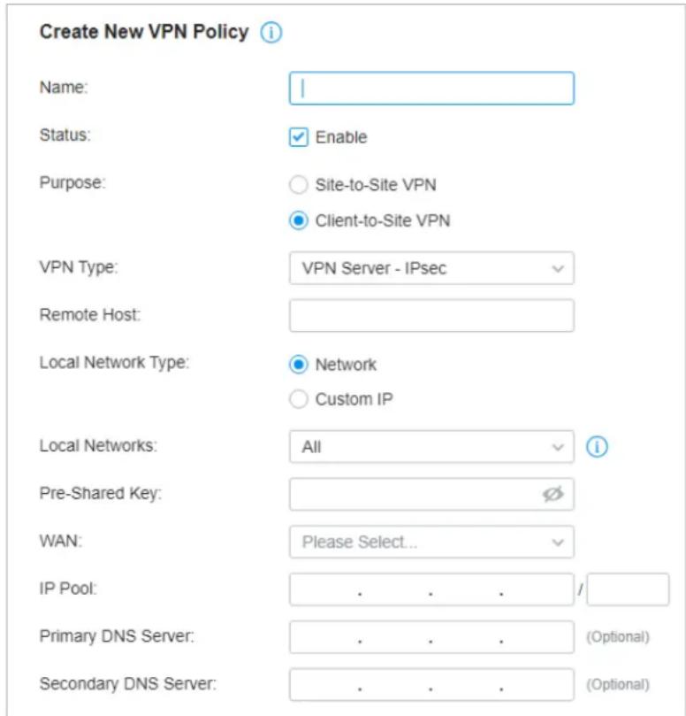
- Enter a name to identify the VPN policy and select the purpose as Client-to-Site VPN. Refer to the following table to configure the basic parameters and click Create.
Name Enter a name to identify the VPN policy.
Status Click the checkbox to enable the VPN policy.
Purpose Select the purpose for the VPN as Client-to-Site VPN.
VPN Type Select the VPN type as VPN Server - IPsec.
Remote Host Enter an IP address or a domain name of the host on the remote peer of the VPN tunnel. 0.0.0.0 represents any IP address.
Local Network Type
Specify whether to apply the VPN policy to specific local networks or IP addresses.
Network: The VPN policy will be only applied to the selected local networks.
Custom IP: The VPN policy will be only applied to the specified IP addresses.
| Local Networks | When selecting Network as the Local Network Type, specify the local networks of the VPN tunnel.When selecting Custom IP as the Local Network Type, specify the IP addresses of the VPN tunnel. You can click + Add New to specify multiple entries or click 📄 to delete them. |
| Pre-Shared Key | Enter the pre-shared key(PSK). Both peer gateways must use the same pre-shared secret key for authentication.A pre-shared key is a string of characters that is used as an authentication key. Both VPN peers create a hash value based on the same pre-shared key and other information. The hash values are then exchanged and verified to authenticate the other party.The pre-shared keys should be long and random for security. Short or predictable pre-shared keys can be easily broken in brute-force attacks. To maintain a high level of security, administrators are recommended to update the pre-shared key periodically. |
| WAN Select the WAN port on which the IPsec VPN tunnel is established. | |
| IP Pool Enter the IP address and subnet mask to decide the range of the VPN IP pool.The VPN server will assign IP address to the remote host when the tunnel is established. You can specify any reasonable IP address that will not cause overlap with the IP address of the LAN on the local peer gateway. | |
| Primary DNS Server | (Optional) Enter the IP address of the primary DNS server provided by your ISP. |
| Secondary DNS Server | (Optional) Enter the IP address of the secondary DNS server, which provides redundancy in case the primary DNS server goes down. |
3. Click Advanced Settings to load the following page.
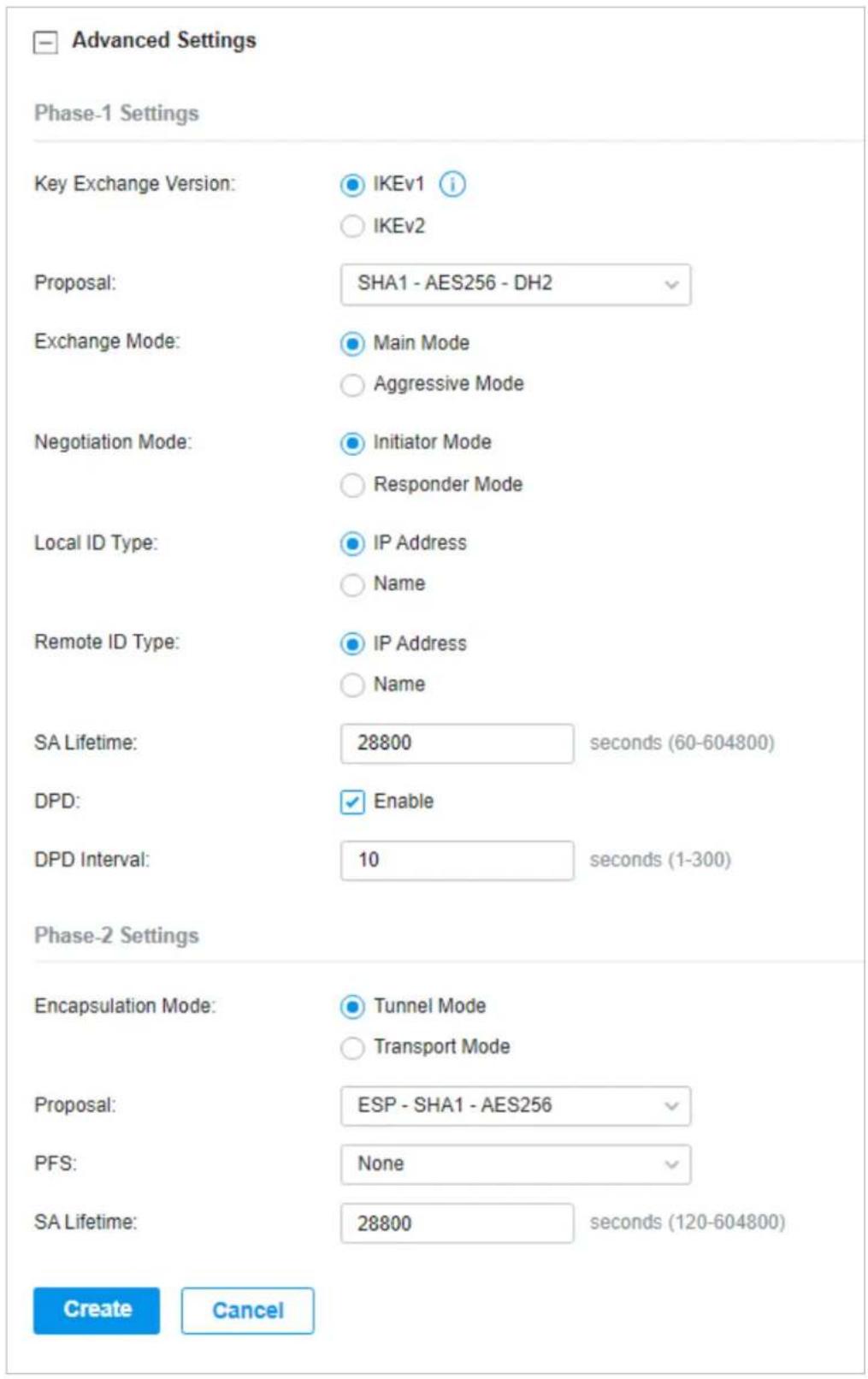
Advanced settings include Phase-1 settings and Phase-2 settings. Phase-1 is used to set up a secure encrypted channel which the two peers can negotiate Phase-2, and then establish the IKE Security Associations (IKE SA). Phase-2 is used to negotiate about a set of parameters that
define what traffic can go through the VPN, and how to encrypt and authenticate the traffic, then establish the IPsec Security Associations (IPsec SA).
Refer to the following table to complete the configurations according to your actual needs and click Create.
For Phase-1 Settings:
| Phase-1 Settings | The IKE version you select determines the available Phase-1 settings and defines the negotiation process. Both VPN gateways must be configured to use the same IKE version and Phase-1 settings. |
| Key Exchange Version | Select the version of Internet Key Exchange (IKE) protocol which is used to set up security associations for IPsec. Both IKEv1 and IKEv2 are supported with gateways, but IKEv1 is available only when the VPN policy is applied to a single Remote Subnet and a single Local Network.Note that both VPN peers must be configured to use the same IKE version. |
| Proposal Specify the proposal for IKE negotiation phase-1. An IKE proposal lists the encryption algorithm, authentication algorithm and Diffie-Hellman (DH) groups to be negotiated with the remote IPsec peer.Authentication algorithms verify the data integrity and authenticity of a message.Encryption algorithms protect the data from being read by a third-party.Diffie-Hellman (DH) groups determine the strength of the key used in the key exchange process.Note that both VPN peers must be configured to use the same Proposal. | |
| Exchange Mode Specify the IKE Exchange Mode as Main Mode or Aggressive Mode when IKEv1 is selected.Main Mode: This mode provides identity protection and exchanges more information, which applies to scenarios with higher requirements for identity protection.Aggressive Mode: This mode establishes a faster connection but with lower security, which applies to scenarios with lower requirements for identity protection. | |
| Negotiation Mode Specify the IKE Negotiation Mode as Initiator Mode or Responder Mode.Initiator Mode: This mode means that the local device initiates a connection to the peer.Responder Mode: This mode means that the local device waits for the connection request initiated by the peer. | |
| Local ID Type | Specify the type of Local ID which indicates the authentication identifier sent to the peer for IKE negotiation. |
| IP Address: Select IP Address to use the IP address for authentication. | |
| Name: Select Name, and then enter the name in the Local ID field to use the name as the ID for authentication. | |
| Note that the type and value of Local ID should be the same as Remote ID given for the remote peer of the VPN tunnel. | |
| Local ID When the Local ID Type is configured as Name, enter a name for the local device as the ID in IKE negotiation. The name should be in the format of FQDN (Fully Qualified Domain Name). | |
| Remote ID Type Specify the type of Remote ID which indicates the authentication identifier received from the peer for IKE negotiation. | |
| Remote ID When the Remote ID Type is configured as Name, enter a name of the remote peer as the ID in IKE negotiation. The name should be in the format of FQDN (Fully Qualified Domain Name). | |
| SA Lifetime | Specify ISAKMP SA (Security Association) Lifetime in IKE negotiation. If the SA lifetime expired, the related ISAKMP SA will be deleted. |
| DPD Check the box to enable DPD (Dead Peer Detect) function. If enabled, the IKE endpoint can send a DPD request to the peer to inspect whether the IKE peer is alive. | |
| DPD Interval | Specify the interval between sending DPD requests with DPD enabled. If the IKE endpoint receives a response from the peer during this interval, it considers the peer alive. If the IKE endpoint does not receive a response during the interval, it considers the peer dead and deletes the SA. |
For Phase-2 Settings:
| Phase-2 Settings | The purpose of Phase 2 negotiations is to establish the Phase-2 SA (also called the IPsec SA). The IPsec SA is a set of traffic specifications that tell the device what traffic to send over the VPN, and how to encrypt and authenticate that traffic. |
| Encapsulation Mode Specify the Encapsulation Mode as Tunnel Mode or Transport Mode. When both ends of the tunnel are hosts, either mode can be chosen. When at least one of the endpoints of a tunnel is a security gateway, such as a gateway or firewall, Tunnel Mode is recommended to ensure safety. | |
Proposal Specify the proposal for IKE negotiation phase-2. An IPsec proposal lists the encryption algorithm, authentication algorithm and protocol to be negotiated with the remote IPsec peer.
Note that both peer gateways must be configured to use the same Proposal.
PFS Select the DH group to enable PFS (Perfect Forward Security) for IKE mode, then the key generated in phase-2 will be irrelevant with the key in phase-1, which enhance the network security. With None selected, it means PFS is disabled and the key in phase-2 will be generated based on the key in phase-1.
SA Lifetime Specify IPsec SA (Security Association) Lifetime in IKE negotiation. If the SA lifetime expired, the related IPsec SA will be deleted.
- Configuring the gateway as a VPN server using OpenVPN
- Select a site from the drop-down list of Organization. Go to Settings > VPN. Click + Create New VPN Policy to load the following page.
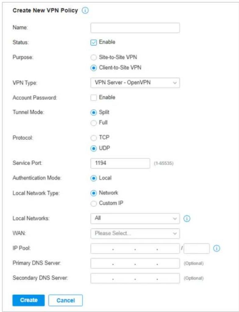
- Enter a name to identify the VPN policy and select the purpose as Client-to-Site VPN. Refer to the following table to configure the required parameters and click Create.
Name Enter a name to identify the VPN policy.
Status Click the checkbox to enable the VPN policy.
Purpose Select the purpose for the VPN as Client-to-Site VPN.
VPN Type Select the VPN type as VPN Server - OpenVPN.
Account Password Specify whether VPN clients need to enter a user account to access the VPN tunnel. When enabled, you need to create accounts on the VPN User page.
Tunnel Mode Select the tunnel mode: Split or Full.
Full tunneling uses the VPN for all your traffic, whereas split tunneling sends part of your traffic through a VPN and part of it through the open network. Full tunneling is more secure than split tunneling.
Protocol Select the communication protocol for the gateway which works as an OpenVPN Server. Two communication protocols are available: TCP and UDP.
Service Port Enter a VPN service port to which a VPN device connects.
Authentication Mode The authentication mode is Local by default.
Local Network Type Specify whether to apply the VPN policy to specific local networks or IP addresses.
Network: The VPN policy will be only applied to the selected local networks.
Custom IP: The VPN policy will be only applied to the specified IP addresses.
Local Networks When selecting Network as the Local Network Type, specify the local networks of the VPN tunnel.
When selecting Custom IP as the Local Network Type, specify the IP addresses of the VPN tunnel. You can click + Add New to specify multiple entries or click 📄 to delete them.
WAN Select the WAN port on which the VPN tunnel is established. Each WAN port supports only one OpenVPN tunnel when the gateway works as a OpenVPN server.
IP Pool Enter the IP address and subnet mask to decide the range of the VPN IP pool.
The VPN server will assign IP address to the remote host when the tunnel is established. You can specify any reasonable IP address that will not cause overlap with the IP address of the LAN on the local peer gateway.
Primary DNS Server (Optional) Enter the IP address of the primary DNS server provided by your ISP.
Secondary DNS Server (Optional) Enter the IP address of the secondary DNS server, which provides redundancy in case the primary DNS server goes down.
- After clicking Create to save the VPN policy, go to VPN Policy List and click in the Action column to export the OpenVPN file that ends in .ovpn which is to be used by the remote client. The exported OpenVPN file contains the certificate and configuration information.

- Configuring the gateway as a VPN client using L2TP
- Select a site from the drop-down list of Organization. Go to Settings > VPN. Click + Create New VPN Policy to load the following page.
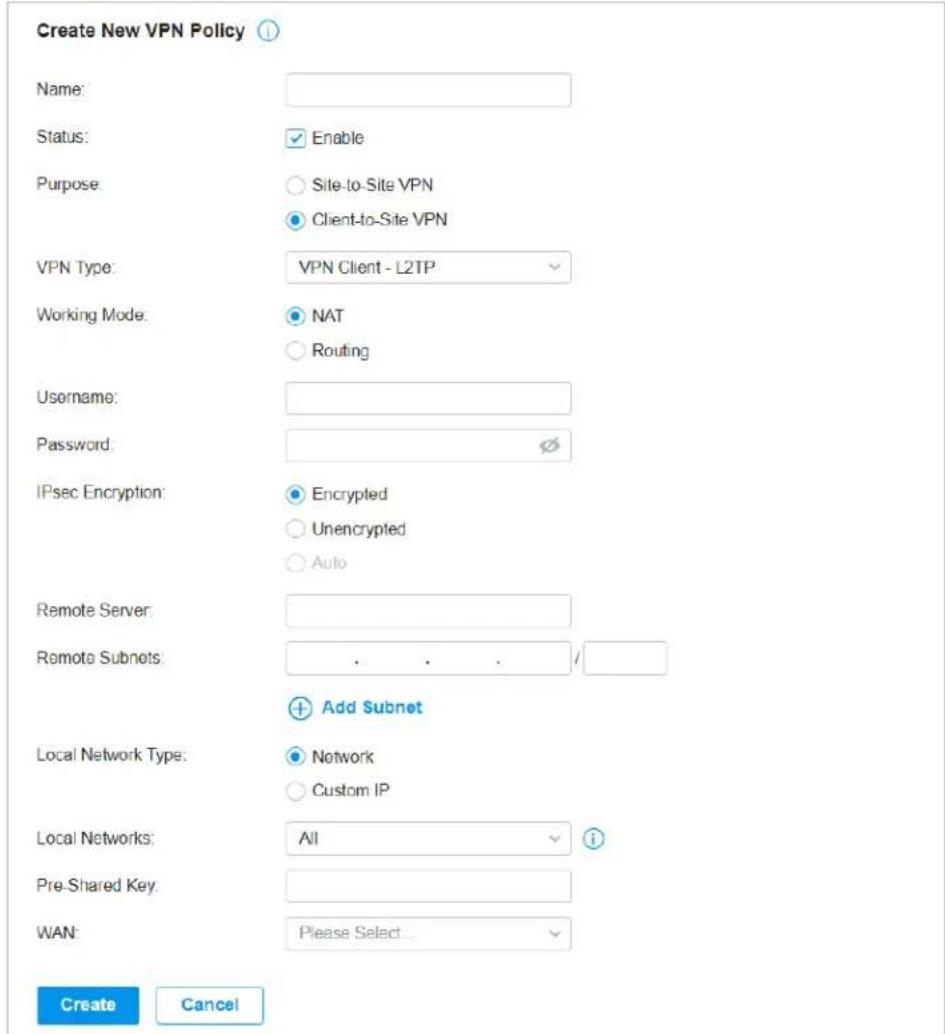
- Enter a name to identify the VPN policy and select the purpose as Client-to-Site VPN. Refer to the following table to configure the required parameters and click Create.
Name Enter a name to identify the VPN policy.
Status Click the checkbox to enable the VPN policy.
Purpose Select the purpose for the VPN as Client-to-Site VPN.
VPN Type Select the VPN type as VPN Client - L2TP.
Working Mode Specify the Working Mode as NAT or Routing.
NAT: With NAT (Network Address Translation) mode selected, the L2TP client uses the assigned IP address as its source addresses of original IP header when forwarding L2TP packets.
Routing: With Routing selected, the L2TP client uses its own IP address as its source addresses of original IP header when forwarding L2TP packets.
Username Enter the username used for the VPN tunnel. This username should be the same as that of the L2TP server.
Password Enter the password of user. This password should be the same as that of the L2TP server.
IPsec Encryption Specify whether to enable the encryption for the tunnel.
Encrypted: Select Encrypted to encrypt the L2TP tunnel by IPsec (L2TP over IPsec). With Encrypted selected, enter the Pre-shared Key for IKE authentication. VPN server and VPN client must use the same pre-shared secret key for authentication.
Unencrypted: With Unencrypted selected, the L2TP tunnel will be not encrypted by IPsec.
Remote Server Enter the IP address or domain name of the L2TP server.
Remote Subnets Enter the IP address range of LAN on the remote peer of the VPN tunnel. Remote subnets should not be in the same network segment as the local LAN. You can click + Add Subnet to specify multiple entries or click 📋 to delete them.
Local Network Type Specify whether to apply the VPN policy to specific local networks or IP addresses.
Network: The VPN policy will be only applied to the selected local networks.
Custom IP: The VPN policy will be only applied to the specified IP addresses.
Local Networks When selecting Network as the Local Network Type, specify the local networks of the VPN tunnel.
When selecting Custom IP as the Local Network Type, specify the IP addresses of the VPN tunnel. You can click + Add New to specify multiple entries or click 📋 to delete them.
Pre-shared Key Enter the pre-shared secret key when the L2TP tunnel is encrypted by IPsec. Both peer gateways must use the same pre-shared secret key for authentication.
WAN Select the WAN port on which the VPN tunnel is established.
- Configuring the gateway as a VPN client using PPTP
- Select a site from the drop-down list of Organization. Go to Settings > VPN. Click + Create New VPN Policy to load the following page.
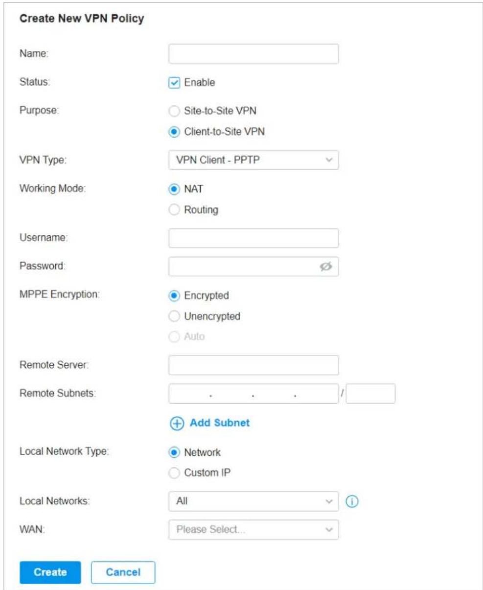
- Enter a name to identify the VPN policy and select the purpose as Client-to-Site VPN. Refer to the following table to configure the required parameters and click Create.
Name Enter a name to identify the VPN policy.
Status Click the checkbox to enable the VPN policy.
Purpose Select the purpose for the VPN as Client-to-Site VPN.
VPN Type Select the VPN type as VPN Client - PPTP.
Working Mode Specify the Working Mode as NAT or Routing.
NAT: With NAT (Network Address Translation) mode selected, the PPTP client uses the assigned IP address as its source addresses of original IP header when forwarding PPTP packets.
Routing: With Routing selected, the PPTP client uses its own IP address as its source addresses of original IP header when forwarding PPTP packets.
Username Enter the username used for the VPN tunnel. This username should be the same as that of the PPTP server.
Password Enter the password of user. This password should be the same as that of the PPTP server.
MPPE Encryption Specify whether to enable the encryption for the tunnel.
Encrypted: Select Encrypted to encrypt the PPTP tunnel by MPPE.
Unencrypted: With Unencrypted selected, the PPTP tunnel will be not encrypted by MPPE.
Remote Server Enter the IP address or domain name of the PPTP server.
Remote Subnets Enter the IP address range of LAN on the remote peer of the VPN tunnel. Remote subnets should not be in the same network segment as the local LAN. You can click + Add Subnet to specify multiple entries or click 📋 to delete them.
Local Network Type Specify whether to apply the VPN policy to specific local networks or IP addresses.
Network: The VPN policy will be only applied to the selected local networks.
Custom IP: The VPN policy will be only applied to the specified IP addresses.
Local Networks When selecting Network as the Local Network Type, specify the local networks of the VPN tunnel.
When selecting Custom IP as the Local Network Type, specify the IP addresses of the VPN tunnel. You can click + Add New to specify multiple entries or click 📄 to delete them.
WAN Select the WAN port on which the VPN tunnel is established.
- Configuring the gateway as a VPN client using OpenVPN
- Select a site from the drop-down list of Organization. Go to Settings > VPN. Click + Create New VPN Policy to load the following page.
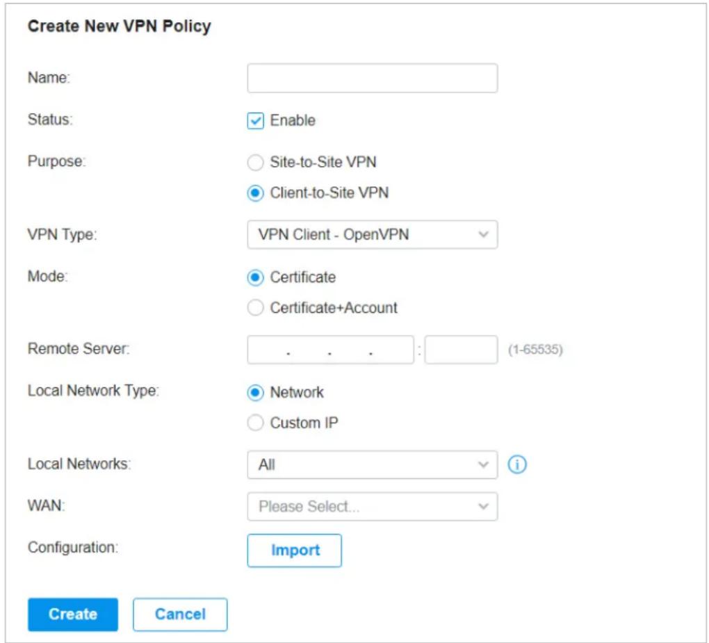
- Enter a name to identify the VPN policy and select the purpose as Client-to-Site VPN. Refer to the following table to configure the required parameters and click Create.
Name Enter a name to identify the VPN policy.
Status Click the checkbox to enable the VPN policy.
Purpose Select the purpose for the VPN as Client-to-Site VPN.
VPN Type Select the VPN type as VPN Client - OpenVPN.
Mode Select the access mode according to VPN requirements.
Certificate: Select this option if the VPN tunnel only requires the certificate.
Certificate+Account: Select this option if the VPN tunnel requires the certificate and VPN user account. If selected, configure the following parameters:
Username: Enter the username for the VPN tunnel.
Password: Enter the password for the VPN tunnel.
| Remote Server Enter the IP address or domain name of the OpenVPN server. | |
| Local Network Type | Specify whether to apply the VPN policy to specific local networks or IP addresses. |
| Network: The VPN policy will be only applied to the selected local networks. | |
| Custom IP: The VPN policy will be only applied to the specified IP addresses. | |
| Local Networks | When selecting Network as the Local Network Type, specify the local networks of the VPN tunnel. |
| When selecting Custom IP as the Local Network Type, specify the IP addresses of the VPN tunnel. You can click + Add New to specify multiple entries or click 📄 to delete them. | |
| WAN Select the WAN port on which the VPN tunnel is established. | |
| Configuration | Click Import to import the OpenVPN file that ends in .ovpn generated by the OpenVPN server. Only one file can be imported. |
| If the certificate file and configuration file are generated singly by the OpenVPN server, combine two files and import the whole file. | |
5.2 VPN User
Overview
VPN User is used to configure and record your custom settings for VPN configurations, and it allows you to configure VPN users that can be used for multiple VPN servers. It saves you from setting the VPN users with the same configurations repeatedly when you want to apply the user in different VPN servers.
Configuration
To configure the VPN users, follow these steps:
- Select a site from the drop-down list of Organization. Go to Settings >VPN>VPN User. Click +Create New VPN User to add a new entry of VPN User.

2. Specify the parameters and click Create.
Create New VPN User ⓘ
This feature is only compatible for Festa gateways with certain firmware versions. Please ensure that your gateway supports the feature before adoption. The configuration will be hidden if the adopted gateway is not compatible.
Username:
Password:
Protocol:
VPN Server:
Local IP Address:
Mode:
Maximum Connections:
Create
Cancel
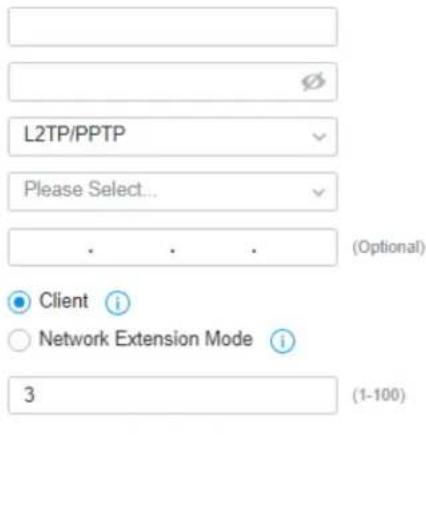
Username Enter the username used for the VPN tunnel. The client use the username for the validation before accessing the network.
Password Enter the password of user. The client uses the password for the validation before accessing the network.
Protocol Select the protocol type for the VPN tunnel.
If you selected the L2TP/PPTP protocol, specify the following parameters:
VPN Server Select the VPN server that the VPN user is applied to.
Local IP Address (Optional) Specify the local IP address of the VPN tunnel.
Mode Specify the connection mode for the VPN users.
Client: This mode allows the client to request for an IP address and the server supplies the IP addresses from the VPN IP Pool. With this mode selected, set maximum number of concurrent VPN connections with the same account in Maximum Connections.
Network Extension Mode: This mode allows only clients from the configured subnet to connect to the server and obtain VPN services. With this mode selected, specify the subnets in Remote Subnets. Remote subnets should not be in the same network segment as the local LAN. You can click + Add Subnet to specify multiple entries or click 📄 to delete them.
If you selected the OpenVPN protocol, specify the following parameter:
VPN Server Select the VPN server that the VPN user is applied to.
To edit or delete the VPN users, click the icon in the Action column. You can further filter the entries based on the VPN Server.


Filter the entries.

View and edit the account information of users.

Delete the VPN user.
6 Create Profiles
Profiles section is used to configure and record your custom settings for site configurations. It includes Time Range, Groups, and Rate Limit profiles.
In Time Range section, you can configure time templates for WLAN Schedule, ACL Time Range, etc. In Groups section, you can configure groups based on IP, IP-Port, IPv6, IPv6-Port or MAC address for ACL, etc. In Rate Limit section, you can set different rate limit templates bound with wireless network to limit the upload/download rate of clients connected the SSID, and applied to specific types of Portal, such as Voucher.
After creating the profiles, you can apply them to multiply configurations for different sites, saving you from repeatedly setting up the same information.
6.1 Time Range
Overview
Time Range allows you to customize time-related configurations. You can set different time range templates which can be shared and applied to WLAN Schedule, ACL Time Range, etc. in site configuration.
Configuration
To configure the time range profiles, follow these steps:
-
Select a site from the drop-down list of Organization. Go to Settings > Profiles > Time Range. Click + Create New Time Range to add a new time range entry. By default, there is no entry in the list.
-
Enter a Name for the new entry, select the Day Mode, and specify the time range. Click +Add to add a new time period, click Apply to save the entry. After saving the newly added entry, you can apply
them to site configuration. To apply the customized time range profiles in configuration, refer to WLAN Schedule.
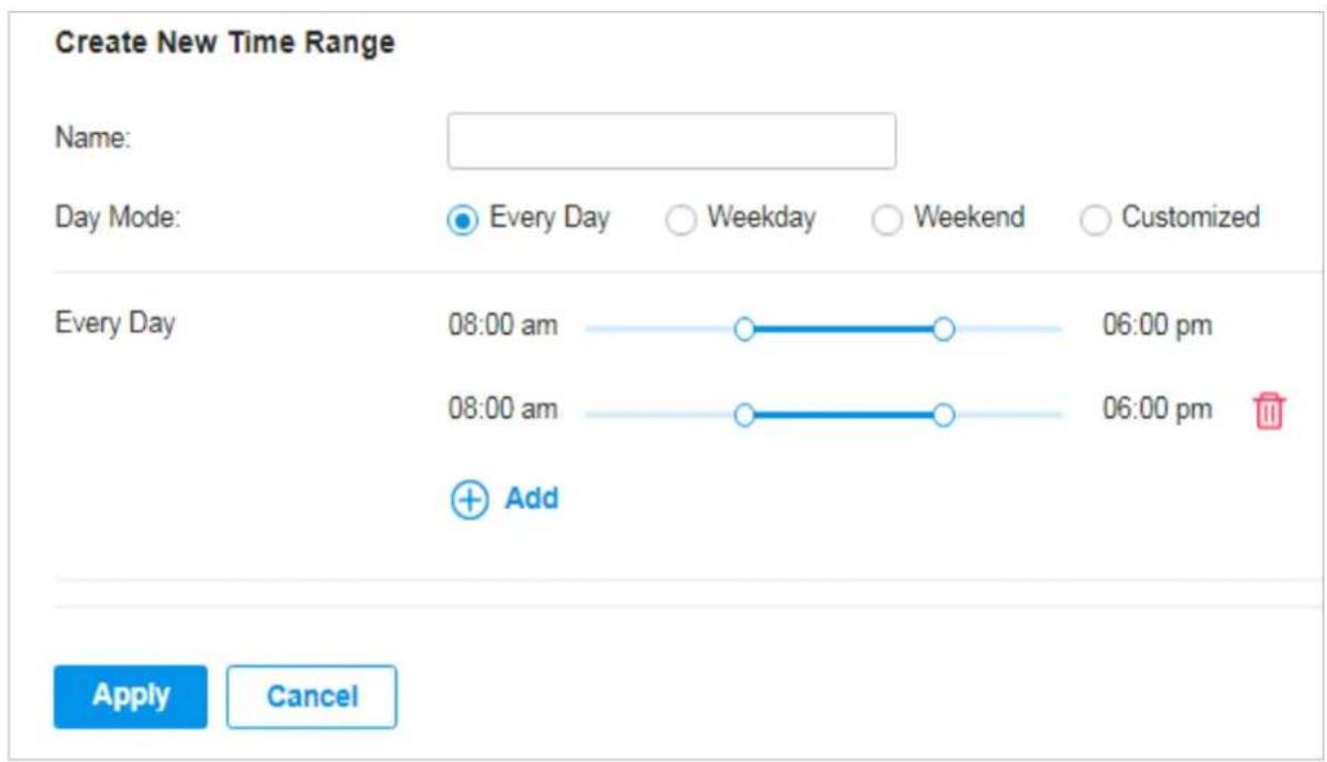
Name Enter a name for the new entry, and it is a string with 1 to 64 ASCII symbols.
| Day Mode | Select Every Day, Weekday, Weekend, or Customized first before specifying the time range for each day.Every Day: You only need to set the time range once, and it will repeat every day.Weekday: You only need to set the time range once, and it will repeat every weekday from Monday to Friday.Weekend: You only need to set the time range once, and it will repeat every Saturday and Sunday.Customized: You are able to set different time range for the chosen day(s) based on your needs. When a day is not chosen, the WiFi is open all day by default. |
You can view the name, day mode and time range in the list.
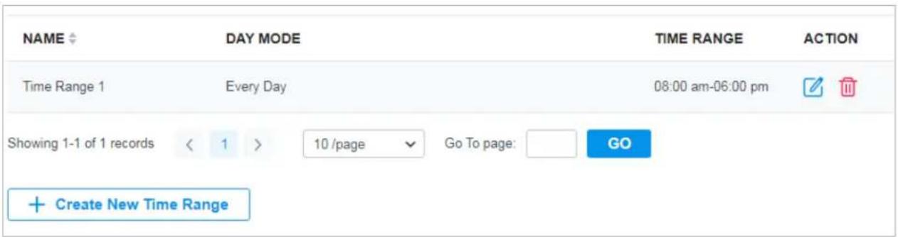
To edit or delete the time range entry, click the icon in the Action column.

Edit the parameters in the entry.

Delete the entry.
6.2 Groups
Overview
Groups section allows you to customize client groups based on IP, IP-Port, IPv6, IPv6-Port or MAC address. You can set different rules for the groups profiles which can be shared and applied to ACL, etc. in site configuration.
Configuration
To configure the group profiles, follow these steps:
- Select a site from the drop-down list of Organization. Go to Settings > Profiles > Groups. Click +Create New Group to add a new group profile.
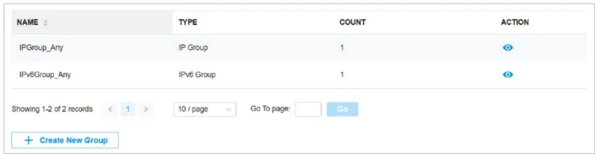
- Enter a name for the new group profile entry, and select the type for the new entry.
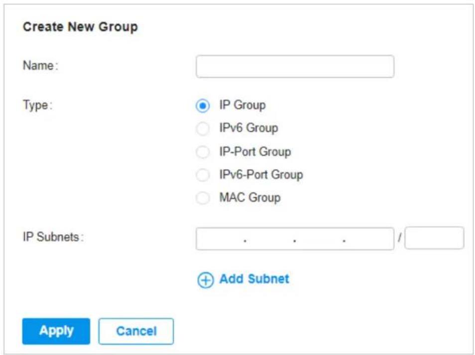
■ To create an IP group profile:
Choose the IP Group type and specify IP subnets.
■ To create an IPv6 group profile:
Choose the IPv6 Group type and specify IPv6 addresses.
■ To Create an IP-Port group profile:
Choose the IP-Port Group type and specify the IP-Port type and ports, while it is optional to specify IP subnets. If you only specify ports without entering any IP subnets, it means the group contains the specified ports for all IP addresses.
■ To create an IPv6-Port group profile:
Choose the IPv6-Port Group type and specify the IP-Port type and ports, while it is optional to specify IPv6 addresses. If you only specify ports without entering any IPv6 addresses, it means the group contains the specified ports for all IPv6 addresses.
■ To configure a MAC group profile:
Choose the MAC Group type and add MAC addresses in the MAC Addresses List.

Add MAC address individually.

Batch Add
Add MAC addresses in batches. You can enter the MAC addresses and names in the input box or import them with files in the format of Excel, txt, and text.
If you want to use the newly added MAC address(es) and names when they conflict with the existing ones, check the box to override the current MAC addresses in the list.
Note:
- Each MAC address and name should be entered on a new line. The MAC address and name should be separated by a space.
- Octets in a MAC address should be separated by a hyphen. For example, AA-BB-CC-DD-EE-FF.

Add from Client List
Add MAC addresses from the clients that are connected to the devices controlled by the SDN Controller.
3. Click Apply to save the entry.
You can view and edit the group list, and export the MAC group if needed. You can apply the customized profiles during site configuration.
| NAME | TYPE | COUNT | ACTION |
| IP Group_1 | IP Group | 2 | |
| IPv6Group_Any | IPv6 Group | 1 | |
| IP-Port Group_1 | IP-Port Group | 1 | |
| IPGroup_Any | IP Group | 1 | |
| IPv6 Group_1 | IPv6 Group | 1 | |
| IPv6-Port Group_1 | IPv6-Port Group | 3 | |
| Location Group_1 | Location Group | 1 | |
| MAC Group_1 | MAC Group | 1 |
6.3 Rate Limit
Overview
Rate Limit allows you to customize rate-related configurations. You can set different rate limit templates. They can be bound with wireless network to limit the upload/download rate of clients connected the SSID, and applied to specific types of Portal, such as Voucher.
Configuration
To configure the rate limit profiles, follow these steps:
- Select a site from the drop-down list of Organization. Go to Settings > Profiles > Rate Limit. By default, there is an entry with no limits, and it can not be deleted. Click +Create New Rate Limit Profile to add a new group entry.
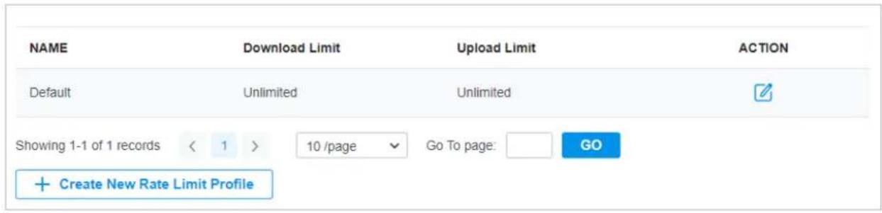
- Enter a name and specify the download/upload rate limit for the new entry. After saving the newly added entry, you can apply them to other configurations such as Portal and Wireless Settings.
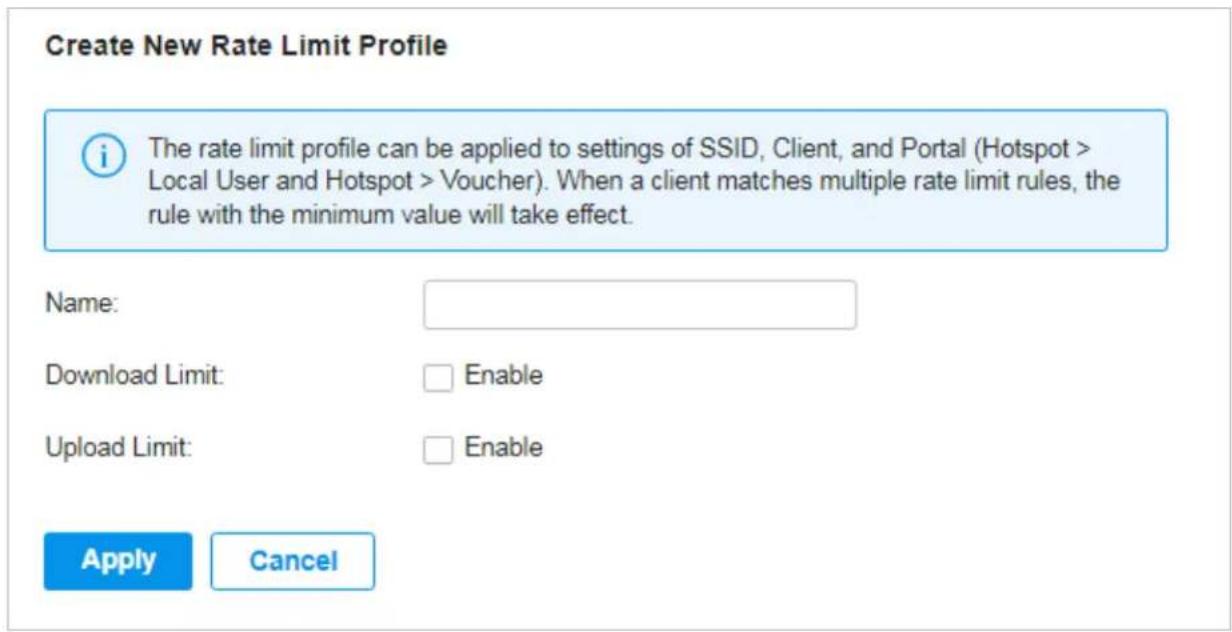
| Name Enter a name to identify the created rate limit profile. | |
| Download Limit | Enable the download limit, and specify the rate limit correspondingly in Kbps or Mbps. |
| Upload Limit | Enable the upload limit, and specify the rate limit correspondingly in Kbps or Mbps. |
- Click Apply to save the entry. After saving the newly added entry, you can apply them to site configuration. To apply the customized rate limit profiles in the related configurations, refer to Portal, and Set Up Basic Wireless Networks.
You can view the name, download limit, and upload limit in the list.
| NAME | Download Limit | Upload Limit | ACTION |
| Default | Unlimited | Unlimited | [1007] |
| Limit-Day | 20000 Kbps | 20000 Kbps | [1485] |
| Limit-Night | 50000 Kbps | 50000 Kbps | [4624] |

To view, edit or delete the rate limit profile, click the icon in the Action column.

View and edit the parameters in the entry. You cannot change the type when editing the entry.

Delete the entry.
♥ 7 Authentication
Authentication is a portfolio of features designed to authorize network access to clients, which enhances the network security. Authentication services include Portal and RADIUS Profile, covering the needs to authenticate both wired and wireless clients.
7.1 Portal
Overview
Portal authentication provides convenient authentication services to the clients that only need temporary access to the network, such as the customers in a restaurant or in a supermarket. To access the network, these clients need to enter the authentication login page and use the correct login information to pass the authentication. In addition, you can customize the authentication login page and specify a URL which the authenticated clients will be redirected to.
Portal authentication takes effect on SSIDs and LAN networks. APs authenticate wireless clients which connect to the SSID with Portal configured, and the gateway authenticates wired clients which connect to the network with Portal configured. To make Portal authentication available for wired and wireless clients, ensure that both the gateway and APs are connected and working properly.
The controller provides several types of Portal authentication:
■ Simple Password
With this authentication type configured, clients are required to enter the correct password to pass the authentication. All clients use the same password which is configured in the controller.
Hotspot
With this authentication type configured, clients can access the network after passing any type of the authentication:
- Voucher
Clients can use the unique voucher codes generated by the controller within a predefined time usage. Voucher codes can be printed out from the controller, so you can print the codes and distribute them to your costumers to tie the network access to consumption.
- Form Auth
Clients are required to fill in a survey created by the network administrator to pass the authentication. It can be used for collecting feedback from your clients.
Portal authentication can work with Access Control Policy, which grant specific network access to the users with valid identities. You can determine that the clients which didn't pass Portal authentication can only access the network resources allowed by Access Control Policy.
■ Pre-Authentication Access
Pre-Authentication Access allows unauthenticated clients to access the specific network resources.
■ Authentication-Free Client
Authentication-Free Clients allows the specific clients to access the specific network resources without authentication.
Create New Portal
- Select a site from the drop-down list of Organization. Go to Settings > Authentication > Portal.
- On Portal tab, click Create New Portal. Specify the portal name and enable Portal.
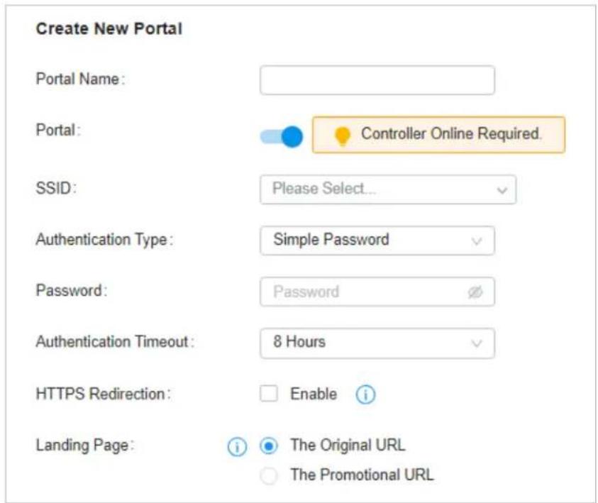
- Select the SSIDs and LAN networks for the portal to take effect. The clients connected to the selected SSIDs or LAN networks will have to log into a web page to establish verification before accessing the network.
- Select the Authentication Type and configure authentication settings.
■ Simple Password
Password Specify the password for the portal.
Authentication Timeout Select the login duration. Clients will be off-line after the authentication timeout.
Hotspot
Type Select one or more authentication types according to your needs. Clients can access the network after passing any type of the authentication.
With different types of Hotspot selected, configure the related parameters.
- Voucher Portal
Voucher
Select Voucher and click to manage the voucher codes.
Refer to Vouchers for detailed information about how to create vouchers.
- Form Authentication
Select Form Auth and click + Create New Survey in the Form Authentication section. Then follow the on-screen instructions to create a survey by adding the type and number of questions you need. You can click Preview to view how the survey looks like on website and phone.
Click Publish and then the created survey can be used for form authentication. A survey cannot be edited after it is published.
Survey Name Specify a name for the survey for identification.
Duration Specify how long clients can use the network after they pass the form authentication.
Created surveys will be displayed for you to choose for the form authentication.
(Optional) Portal Customization
When creating or editing a portal entry, you can customize the Portal page in the Portal Customization section.

Note:
Portal Customization is not available when you configure external authentication types.
Portal Customization
Default Language :
English


Background:

Solid Color

Picture
Logo:

Enable
Logo Size:

Logo Position:

Input Box Color:

Input Text Color:

Button Color:

Button Text color:

Button Position:

Button Text:
Log In
Welcome Information:
Enable
Terms of Service:
Enable
Copyright:
Enable
Show Redirection Countdown
Enable
After Authorized:
| Default Language | Select the default language displayed on the Portal page. The controller automatically adjusts the language displayed on the Portal page according to the system language of the clients. If the language is not supported, the controller will use the default language specified here. |
| Background Select the background type. | |
| Solid Color: Configure your desired background color by entering the hexadecimal HTML color code manually or through the color picker.Picture: Click Choose and select a picture from your PC as the background. | |
| Logo | Click to show the logo on the portal page. |
| Logo Size/Logo Position | Adjust the logo size and position on the Portal Page. |
| Input Box Color/Input Text Color | (For certain authentication types) Configure your desired background and text color for the input box by entering the hexadecimal HTML color code manually or through the color picker. |
| Button Color/Button Text Color | Configure your desired background and text color for the button by entering the hexadecimal HTML color code manually or through the color picker. |
| Button Position Select the button position on the Portal Page. | |
| Button Text Enter the text for the button. | |
| Welcome Information Click the checkbox and enter text as the welcome information.You can specify the desired text font size and configure the text color by entering the hexadecimal HTML color code manually or through the color picker. | |
| Terms of Service | Click the checkbox and enter text as the terms of service in the following box. Click Add Terms to enter the name and context of the terms which will appear after a client clicks the link in Terms of Service. |
| Copyright Click the checkbox and enter text as the copyright in the following box.You can specify the desired text font size and configure the text color by entering the hexadecimal HTML color code manually or through the color picker. | |
| Show Redirection Countdown After Authorized | When enabled, the system will show the portal's redirection countdown. |
(Optional) Access Control
On Access Control tab, you can configure access control rules if needed.
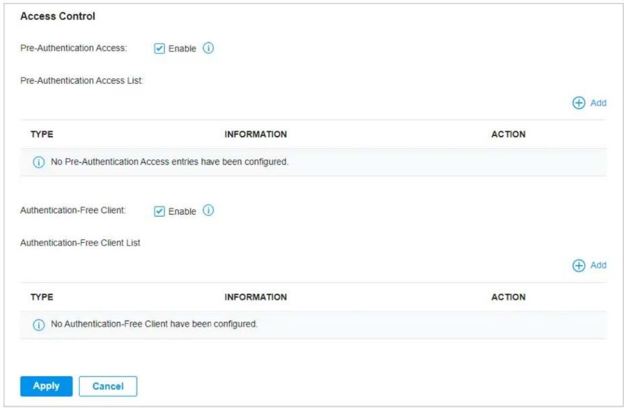
| Pre-Authentication Access | Click the checkbox to enable Pre-Authentication Access. With this feature enabled, unauthenticated clients are allowed to access the subnets and web resources specified in the Pre-Authentication Access List below. |
| Pre-Authentication Access List | Click + Add to configure the IP range or URL which unauthenticated clients are allowed to access. |
| Authentication-Free Policy | Click the checkbox to enable Authentication-Free Policy. With this feature enabled, you can allow certain clients to access the internet without Portal authentication. |
| Authentication-Free Client List | Click + Add and enter the IP address or MAC address of Authentication-Free clients. |
7.2 RADIUS Profile
Overview
RADIUS (Remote Authentication Dial In User Service) is a client/server protocol that provides for the AAA (Authentication, Authorization, and Accounting) needs in modern IT environments.
In authentication services, network devices operate as clients of RADIUS to pass user information to designated RADIUS servers. A RADIUS server maintains a database which stores the identity
information of legal users. It authenticates users against the database when the users are requesting to access the network, and provides authorization and accounting services for them.
A RADIUS profile records your custom settings of a RADIUS server. After creating a RADIUS profile, you can apply it to multiple authentication policies like Portal, saving you from repeatedly entering the same information.
Configuration
To create a new RADIUS profile, follow these steps:
- Select a site from the drop-down list of Organization. Go to Settings > Authentication > RADIUS Profile.
- Click Create New RADIUS Profile. Configure the parameters and save the settings.
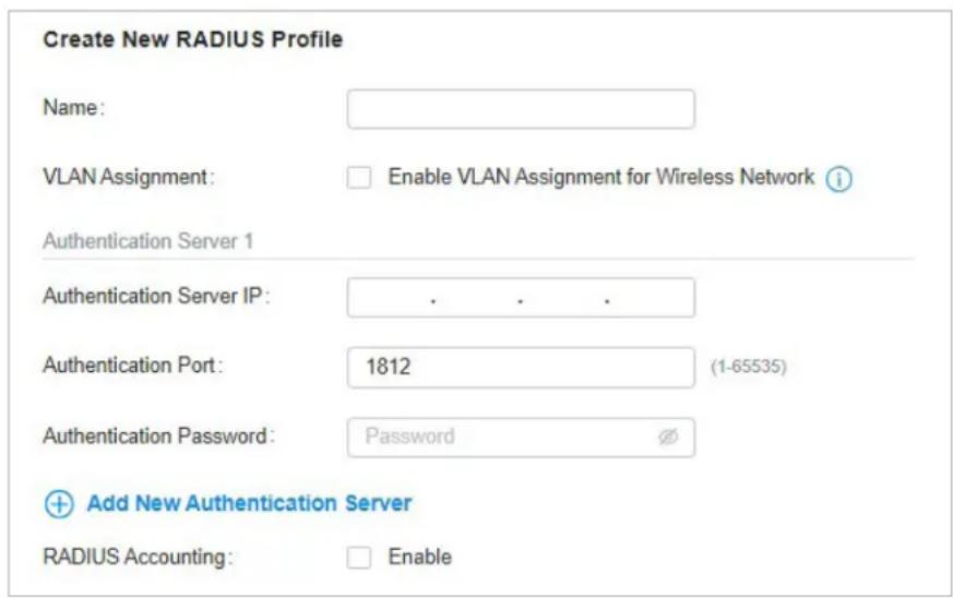
Name Enter a name to identify the RADIUS profile.
| VLAN Assignment | This feature allows the RADIUS server to place a wireless user into a specific VLAN based on the credentials supplied by the user. To use the feature, you should create the specific VLAN first. And the user-to-VLAN mappings must be already stored in the RADIUS server database.Note:1. VLAN Assignment is not currently supported when a client is authenticated by Portal with External RADIUS Server or RADIUS Hotspot.2. VLAN Assignment is applicable only when the device supports the feature. To make this feature work properly, it is recommended to upgrade your devices to the latest firmware version. |
| Authentication Server IP | Enter the IP address of the authentication server. |
| Authentication Port | Enter the UDP destination port on the authentication server for authentication requests. |
| Authentication Password | Enter the password that will be used to validate the communication between network devices and the RADIUS authentication server. |
| RADIUS Accounting | Click the checkbox to enable RADIUS Accounting to meet billing needs. This feature is only available for APs with Portal to account for wireless clients. |
| Interim Update Click the checkbox to enable Interim Update. By default, the RADIUS accounting process needs only start and stop messages to the RADIUS accounting server. With Interim Update enabled, network devices will periodically send an Interim Update (a RADIUS Accounting Request packet containing an “interim-update” value) to the RADIUS server. An Interim Update updates the user’s session duration and current data usage. | |
| Interim Update Interval | Enter an appropriate interval between the updates of users’ session duration and current data usage. |
| Accounting Server IP Enter the IP address of the RADIUS accounting server. | |
| Accounting Port Enter the UDP destination port on the RADIUS server for accounting requests. | |
| Accounting Password | Enter the password that will be used to validate the communication between network devices and the RADIUS accounting server. |

8
Services
Services provide convenient network services and facilitate network management. You can configure servers or terminals in DDNS, SNMP, and SSH, and more.
8.1 Dynamic DNS
Overview
WAN IP Address of your gateway can change periodically because your ISP typically employs DHCP among other techniques. This is where Dynamic DNS comes in. Dynamic DNS assigns a fixed domain name to the WAN port of your gateway, which facilitates remote users to access your local network through WAN Port.
Let's illustrate how Dynamic DNS works with the following figures.
Before:
- WAN IP Address can change periodically, if it's dynamically assigned by the ISP using DHCP among other techniques.
- Remote User doesn't know what WAN IP Address is exactly at the moment, and cannot access Local Network.
Not sure about WAN IP Address. Can't access Local Network.

Remote User

WAN IP Address changes: 2020/05/27: 172.217.174.196 2020/05/28: 172.217.174.208
WAN Port

Gateway
Local Network
After:
- Remote User can simply use Domain Name to access Local Network through WAN Port. In this example, Domain Name is mysite.ddns.net.
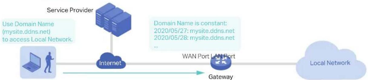
flowchart
graph LR
    A["Service Provider"] --> B["Internet"]
    B --> C["WAN Port LAN Port"]
    C --> D["Local Network"]
    style A fill:#f9f,stroke:#333
    style B fill:#ccf,stroke:#333
    style C fill:#cfc,stroke:#333
    style D fill:#fcc,stroke:#333
Remote User
Prerequisite:
- Choose one Service Provider from the five that the controller supports, i.e. DynDNS, No-IP, Peanuthull, Comexe, Custom.
- Register at your Service Provider, then you get your Username and Password.
• Get your Domain Name from your Service Provider.
How Dynamic DNS works:
1 Gateway informs Service Provider of WAN IP Address.
② Service Provider binds WAN IP Address with Domain Name and keeps it updated as WAN IP Address changes.
③ Remote User requests for WAN IP Address by sending Domain Name to Service Provider.
4 Service Provider replies with WAN IP Address, which Remote User actually uses to access Local Network through WAN Port.
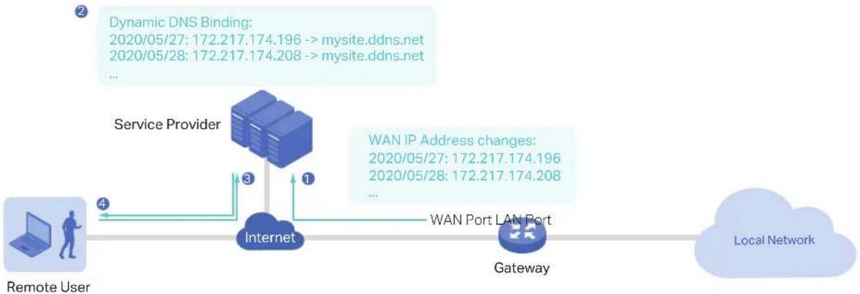
flowchart
graph LR
    A["Remote User"] -->|4| B["Service Provider"]
    B -->|3| C["Internet"]
    C -->|1| D["WAN Port LAN Port"]
    D --> E["Gateway"]
    E --> F["Local Network"]
    G["Dynamic DNS Binding: 2020/05/27: 172.217.174.196 --> mysite.ddns.net\n2020/05/28: 172.217.174.208 --> mysite.ddns.net"] --> H["Local Network"]
    I["WAN IP Address changes: 2020/05/27: 172.217.174.196\n2020/05/28: 172.217.174.208"] --> H
Configuration
Select a site from the drop-down list of Organization. Go to Settings > Services > Dynamic DNS. Click + Create New Dynamic DNS Entry, to load the following page. Configure the parameters and click Create.
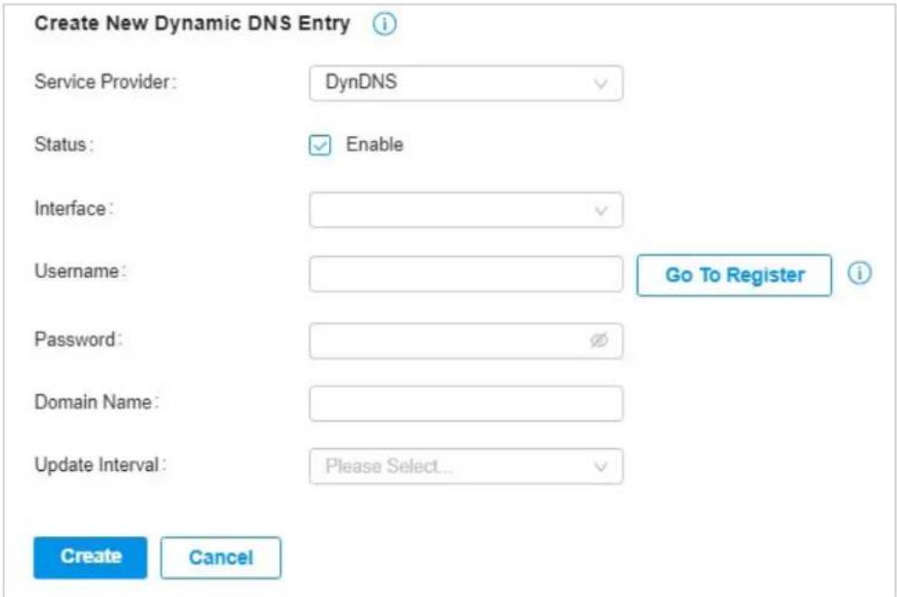
| Service Provider Select your service provider which Dynamic DNS works with. | |
| Status Enable or disable the Dynamic DNS entry. | |
| Interface Select the WAN Port which the Dynamic DNS entry applies to. | |
| Username | Enter your username for the service provider. If you haven't registered at the service provider, click Go To Register. |
| Password Enter your password for the service provider. | |
| Domain Name | Enter the Domain Name which is provided by your service provider. Remote users can use the Domain Name to access your local network through WAN port. |
| Update Interval | Specify the update interval to report the changes of the WAN IP address for the DDNS service. |
| Update-URL | When choosing Custom as the Dynamic DNS Service Provider, you will need to enter the URL provided by your DDNS service provider in format of "http://[USERNAME]:[PASSWORD]@ api.cp.easydns.com/dyn/tomato.php?hostname=[DOMAIN]&myip=[IP]". The gateway will automatically update user information to the service provider. |
8.2 SNMP
Overview
SNMP (Simple Network Management Protocol) provides a convenient and flexible method for you to configure and monitor network devices. Once you set up SNMP for the devices, you can centrally manage them with an NMS (Network Management Station).
The controller supports multiple SNMP versions including SNMPv1, SNMPv2c and SNMPv3.

Note:
If you use an NMS to manage devices which are managed by the controller, you can only read but not write SNMP objects.
Configuration
Select a site from the drop-down list of Organization. Go to Settings > Services > SNMP and configure the parameters. Then click Apply.
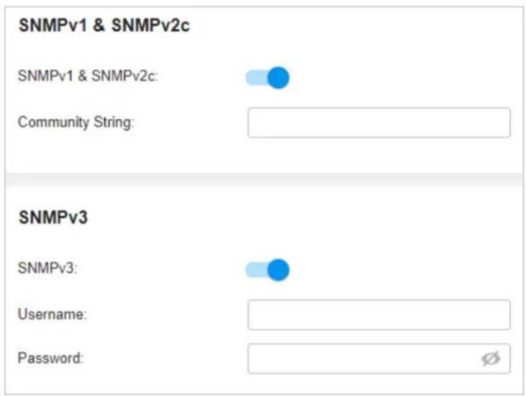
SNMPv1 & SNMPv2c Enable or disable SNMPv1 and SNMPv2c globally.
Community String
With SNMPv1 & SNMPv2c enabled, specify the Community String, which is used as a password for your NMS to access the SNMP agent. You need to configure the Community String correspondingly on your NMS.
SNMPv3 Enable or disable SNMPv3 globally.
Username With SNMPv3 enabled, specify the username for your NMS to access the SNMP agent. You need to configure the username correspondingly on your NMS.
Password With SNMPv3 enabled, specify the password for your NMS to access the SNMP agent. You need to configure the password correspondingly on your NMS.
8.3 SSH
Overview
SSH (Secure Shell) provides a method for you to securely configure and monitor network devices via a command-line user interface on your SSH terminal.

Note:
If you use an SSH terminal to manage devices which are managed by the controller, you can only get the User privilege.
Configuration
Select a site from the drop-down list of Organization. Go to Settings > Services > SSH. Enable SSH Login globally and configure the parameters. Then click Apply.
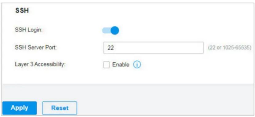
| SSH Server Port | Specify the SSH Sever Port which your network devices use for SSH connections. You need to configure the SSH Server Port correspondingly on your SSH terminal. |
| Layer 3 Accessibility | With this feature enabled, the SSH terminal from a different subnet can access your devices via SSH. With this feature disabled, only the SSH terminal in the same subnet can access your devices via SSH. |
8.4 IPTV
Overview
IPTV includes two sections: IGMP and IPTV. In IGMP settings, you can enable IGMP proxy to detect multicast group membership information and thus the gateway is able to forward multicast packets based upon the information. IPTV settings allows you to enable Internet/IPTV/Phone service provided by your ISP.
Configuration
- Select a site from the drop-down list of Organization. Go to Settings > Services > IPTV > IGMP, configure the parameters. If you want to configure the IPTV settings, go to next step; if you don't want to configure the IPTV settings, click Apply.
IGMP
IGMP Proxy:
IGMP Version:
IGMP Interface:

v2
Please Select...
IGMP Proxy Enable IGMP Proxy.
IGMP Proxy sends IGMP querier packets to the LAN ports to detect if there is any multicast member connected to the LAN ports.
IGMP Version Select the IGMP version as V2 or V3. The default is IGMP V2.
IGMP Interface Select the WAN port on which the IGMP Proxy takes effect.
- Go to Settings > Services > IPTV > IPTV, enable the IPTV features and choose the mode as Bridge or Custom according to your ISP. Then configure the corresponding parameters. Click Apply.
Note that the IPTV section will be hidden if your device is an earlier version that does not support this feature.
IPTV
IPTV:

Mode:
Bridge
Custom i
WAN Port:
Please Select...

WAN/LAN3:
Internet

WAN/LAN4:
Internet

WAN/LAN5:
Internet

WAN/LAN6:
Internet

IPTV Enable IPTV feature.
Mode Select the appropriate Mode according to your ISP.
Bridge: Select this mode if your ISP requires no other parameters.
Custom: Select this mode if your ISP provides necessary parameters, and configure the parameters according to the requirements of your ISP.
WAN Port Select the WAN port on which the IPTV settings take effect.
WAN/LAN Select the service supported by the specific LAN port.
Monitor the Network
This chapter guides you on how to monitor the network devices, clients, and their statistics. Through visual and real-time presentations, the Controller keeps you informed about the accurate status of the managed network. This chapter includes the following sections:
• 1 View the Status of Network with Dashboard
• 2 Monitor the Network with Map
• 3 View the Statistics During Specified Period with Insights
• 4 View and Manage Logs
• 5 Monitor the Network with Tools
1 View the Status of Network with Dashboard
1.1 Page Layout of Dashboard
Dashboard is designed for a quick real-time monitor of the site network. An overview of network topology is at the top of Dashboard, and the below are widgets that illustrate the traffic status of wireless networks and clients in the site.
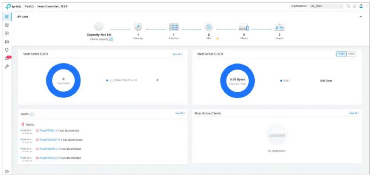
Topology Overview
Topology Overview on the top shows the numbers of devices, clients and guests.

flowchart
graph LR
    A["Capacity Not Set\nInternet Capacity"] --> B["1\nGateway"]
    B --> C["1\nSwitches"]
    C --> D["2\nAPs"]
    D --> E["0\nClients"]
    E --> F["0\nGuests"]
You can hover the cursor over the gateway, switch, AP, client, or guest icons to check their status. For detailed information, click the icon here to jump to the Devices or Clients section.
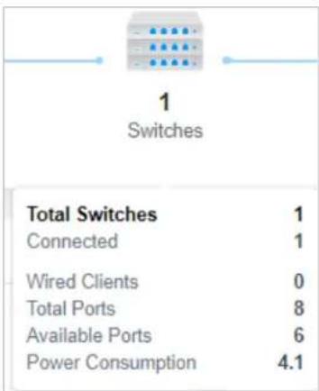
1.2 Explanation of Widgets
The widgets are divided into four parts: Most Active EAPs, Most Active SSIDs, Alerts, and Most Active Clients. These widgets use lists and charts to illustrate the traffic status of wireless networks and clients in the site. You need to manually refresh the page to update the statistics shown on the widgets.
■ Most Active EAPs
The widget can display 15 most active EAPs in the site based on the total number of traffic within the time range. Only the devices that has been adopted by the controller will be displayed.
To view all the devices discovered by the controller, click See All to jump to the Devices section. You can also click the traffic number in the widget to open the device's Properties window for further configurations and monitoring. For details, refer to Manage, Configure, and Monitor Devices.
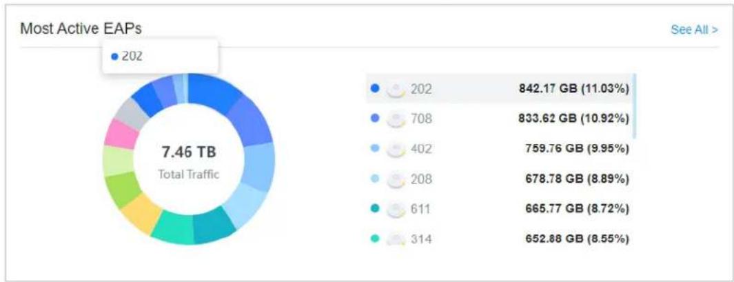
pie
Most Active EAPs | Category | Value (GB) | Percentage (%) | |---|---|---| | 202 | 842.17 | 11.03 | | 708 | 833.62 | 10.92 | | 402 | 759.76 | 9.95 | | 208 | 678.78 | 8.89 | | 611 | 665.77 | 8.72 | | 314 | 652.88 | 8.55 | Total Traffic (7.46 TB)■ Most Active SSIDs
On Traffic tab, the widget can display 5 most active SSIDs in the site based on the total number of traffic within the time range, while other SSIDs will be merged into Others.
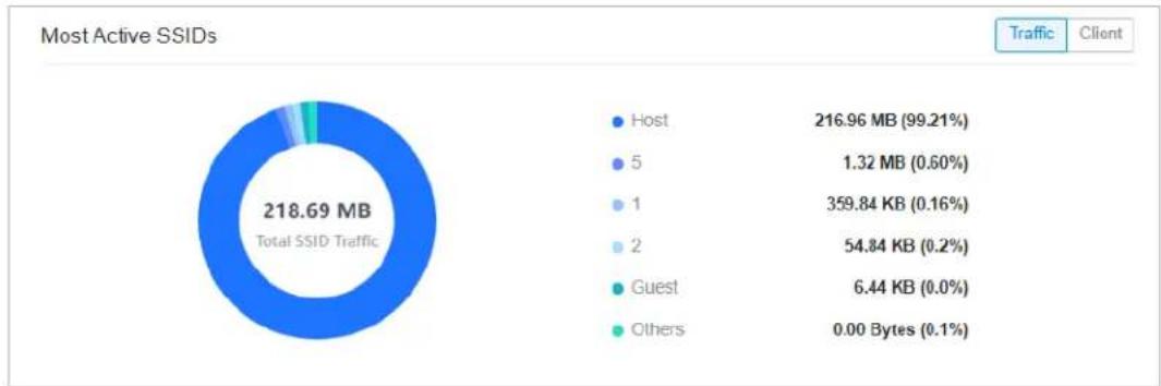
pie
Most Active SSIDs | Client | Volume (MB) | Percentage (%) | | :--- | :--- | :--- | | Host | 216.96 | 99.21 | | 5 | 1.32 | 0.60 | | 1 | 359.84 | 0.16 | | 2 | 54.84 | 0.2 | | Guest | 6.44 | 0.0 | | Others | 0.00 | 0.1 |On Client tab, the widget displays the number of clients connected to the corresponding SSIDs.
For details, refer to Configure Wireless Networks.
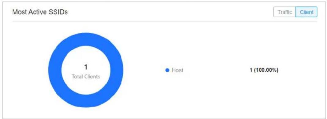
pie
Most Active SSIDs | Category | Count | | :--- | :--- | | Total Clients | 1 | | Host | 1 (100.00%) |Alerts
The Alerts widget displays the total number of unarchived alerts happened in the site and details of the latest five. To view all the alerts and archive them, click See All to jump to Log > Alerts. To specify events appeared in Alerts, go to Log > Notifications and configure the events as the Alert level. For details, refer to View and Manage Logs.
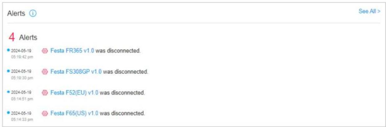
■ Most Active Clients
The widget can display 15 most active clients. Only the clients in the connected status currently will be displayed.
To view all the clients connected to the network, click See All to jump to the Clients section. You can also click the traffic number in the widget to open the client's Properties window for further configurations and monitoring. For details, refer to Manage Wired and Wireless Clients in Clients
Page.
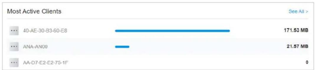
bar
Most Active Clients | Client | Value (MB) | | :--- | :--- | | 40-AE-30-B3-60-E8 | 171.53 | | ANA-AN00 | 21.57 | | AA-D7-E2-E2-75-1F | 0 |2 Monitor the Network with Map
With the Map function, you can look over the topology and device provisioning of network in Topology, and customize a visual representation of your network in Heat Map.
2.1 Topology
Go to Map > Topology, and you can view the topology generated by the controller automatically. You can click the icon of devices to open the Properties window. For detailed configuration and monitoring in the Properties window, refer to Manage, Configure, and Monitor Devices.
For a better overview of the network topology, you can control the display of branches and the size of the diagram, and view the link labels. You need to manually refresh the page to update the topology.
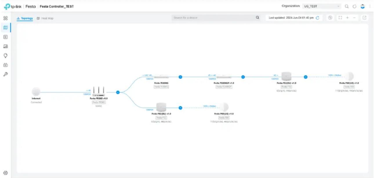
flowchart
graph LR
    A["Internet Connected"] --> B["Festa FS30G"]
    B --> C["Festa FS30NG"]
    C --> D["Festa FS30GCP"]
    D --> E["Festa FS2(EU) v1.0"]
    E --> F["Festa FS2(US) v1.0"]
    B --> G["Festa FS30G"]
    G --> H["Festa FS30NG"]
    H --> I["Festa FS30GCP"]
    I --> J["Festa FS2(EU) v1.0"]
    J --> K["Festa FS2(US) v1.0"]
    B --> L["Festa FS30G"]
    L --> M["Festa FS30NG"]
    M --> N["Festa FS30GCP"]
    N --> O["Festa FS2(EU) v1.0"]
    O --> P["Festa FS2(US) v1.0"]
    B --> Q["Festa FS30G"]
    Q --> R["Festa FS30NG"]
    R --> S["Festa FS30GCP"]
    S --> T["Festa FS2(EU) v1.0"]
    T --> U["Festa FS2(US) v1.0"]
    B --> V["Festa FS30G"]
    V --> W["Festa FS30NG"]
    W --> X["Festa FS30GCP"]
    X --> Y["Festa FS2(EU) v1.0"]
    Y --> Z["Festa FS2(US) v1.0"]
    B --> AA["Festa FS30G"]
    AA --> AB["Festa FS30NG"]
    AB --> AC["Festa FS30GCP"]
    AC --> AD["Festa FS2(EU) v1.0"]
    AD --> AE["Festa FS2(US) v1.0"]
    B --> AF["Festa FS30G"]
    AF --> AG["Festa FS30NG"]
    AG --> AH["Festa FS30GCP"]
    AH --> AI["Festa FS2(EU) v1.0"]
    AI --> AJ["Festa FS2(US) v1.0"]
    B --> AK["Festa FS30G"]
    AK --> AL["Festa FS30NG"]
    AL --> AM["Festa FS30GCP"]
    AM --> AN["Festa FS2(EU) v1.0"]
    AN --> AO["Festa FS2(US) v1.0"]
    B --> AP["Festa FS30G"]
    AP --> AQ["Festa FS30NG"]
    AQ --> AR["Festa FS30GCP"]
    AR --> AS["Festa FS2(EU) v1.0"]
    AS --> AT["Festa FS2(US) v1.0"]
    B --> AU["Festa FS30G"]
    AU --> AV["Festa FS30NG"]
    AV --> AW["Festa FS30GCP"]
    AW --> AX["Festa FS2(EU) v1.0"]
    AX --> AY["Festa FS2(US) v1.0"]
■ Display of Branches
The default view shows the all devices connected by solid and dotted lines. Click the nods ② to unfold or - to fold the branches.
■ Diagram Size
Click the icons at the right corner to adjust the size of the topology and view the legends.
| Click to show internet traffic of mesh APs on the topology. | |
| Click to fit the topology to the web page. | |
| + | Click to zoom in the topology. |
| - | Click to zoom out the topology. |

Click to download the topology in the .png format.
■ Link Labels
Link labels on the topology display the link status. Information on the labels varies according to the link connections.
| -> #21000FDX | (For the WAN port of gateway connected to the Internet) Displays the port name, link speed and duplex type. |
| #16<->#11000FDX | (For simple wired connections) Displays the connected port number, link speed, and duplex type. Note that only the switch's port number can be displayed in the label. |
| -> LAG 1#4,5 <-> LAG 2#7,81000 FDX | (For Link Aggregation) Displays the LAG ID, port number of LAG members, LAG speed, and duplex type. |
| 100% (-36dBm) | (For wireless connection of APs) Displays the RSSI (displayed in percentage and dBm). |
2.2 Heat Map
Go to Map > Heat Map, and a default map is shown as below. You can upload your local map images and add devices and different types of walls to customize a visual representation of your network.
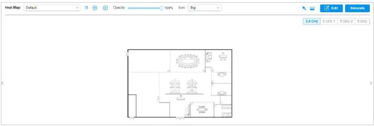
Click the following icons to add, edit, and select the map. After selecting a map, click and drag in the devices from the Devices list to place it on the map according to the actual locations.
Map: TP-Link
Click to select a map from the drop-down list to place the devices.
| Click to edit maps in the pop-up window.Clickto edit the description and layout of the map.Clickto copy the layout of the map.Clickto delete the map. Note that the map cannot be deleted when there is only one map. | |
| Click to add a map. In the pop-up window, enter the description, select the layout, and upload an image in the .jpg, .jpeg, .gif, .png, .bmp, .tiff, or .dxf format. | |
| Opacity 100% | Adjust the opacity of the map. |
| Icon: Small | Click to select the icon size displayed on the map. |
| Click to use the selection tool to select the elements including walls and devices on the map. | |
| Click to use the measurement tool. Draw a line on the map to measure the actual distance according to the map scale. | |
| Edit | Click to edit the elements including walls and devices on the map. |
| Simulate | Click to simulate the network heat map.Note: It is required to click Simulate to generate a new heat map after editing elements on the map. |
| Click to fit the map to the web page. | |
| + | Click to zoom in the map. |
| - | Click to zoom out the map. |
| 10.73m | Click to set the map scale. Draw a line on the map by clicking and dragging, and then define the distance of the line. |
| Click to set the default height of the added devices and the information displayed on the map. |
Configuration
To generate a visual representation and heat map of your network, follow these steps:
1) Add a map and configure the general parameters for the map.
2) Add devices and walls, and configure the parameters.
3) View simulation results.
Add Map Add Devices and Walls View Results
1. Go to Map > Heat Map and click ⭕ to add a new map. Then click Add.
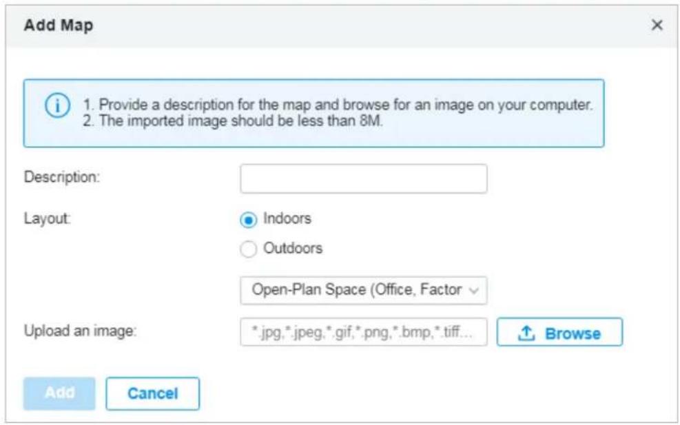
Description Enter a description for the map.
Layout Select the general layout of the map, which will make the simulation more accurate.
Upload an image Upload the map in the .jpg, .jpeg, .gif, .png, .bmp, .tiff, .dxf format.
-
Click on the upper right to set a map scale. Draw a line on the map by clicking and dragging, and then define the distance of the line.
-
Click 🔒 to set the default height of the added devices and the information displayed on the map. Then click Confirm.
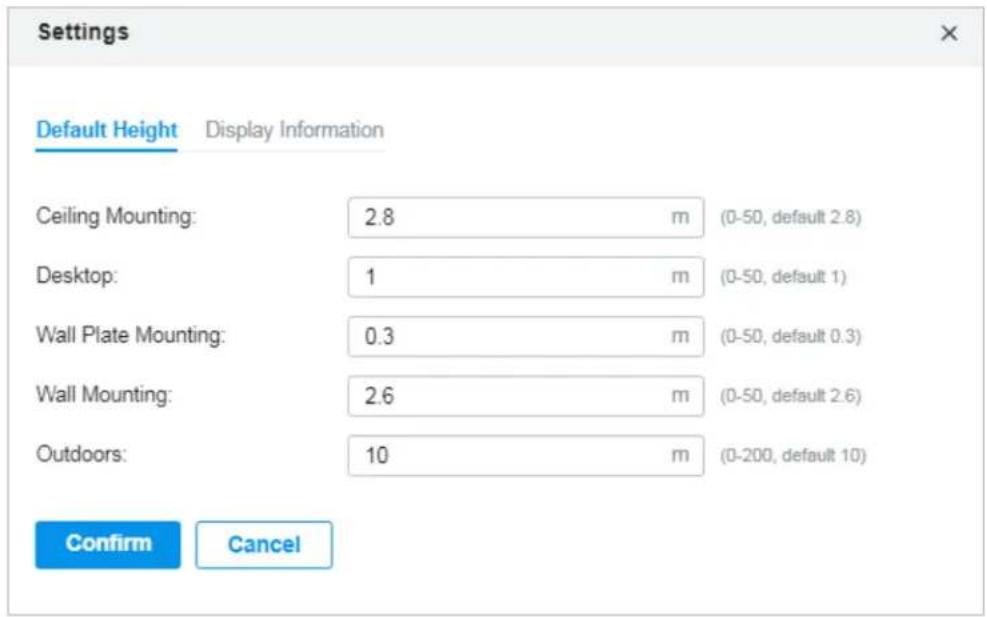
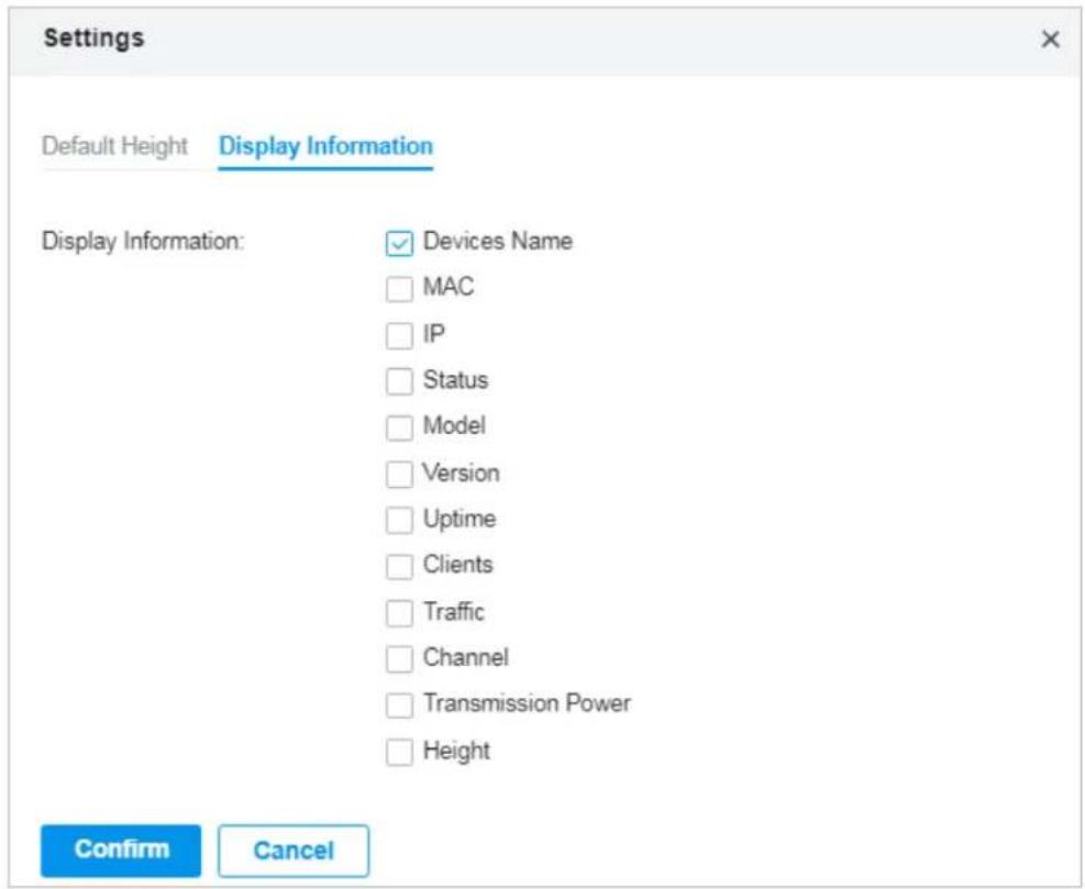
Default Height
Specify the default height for devices. You can change the height for individual device later.
Display Information Select the information you want to see on the map.
Add Map Add Devices and Walls You'll get
-
Click to enter the editing status of the map.
-
Click ☐ on the upper left, and the list of adopted devices and virtual devices will appear. Drag the devices to the desired place on the map.
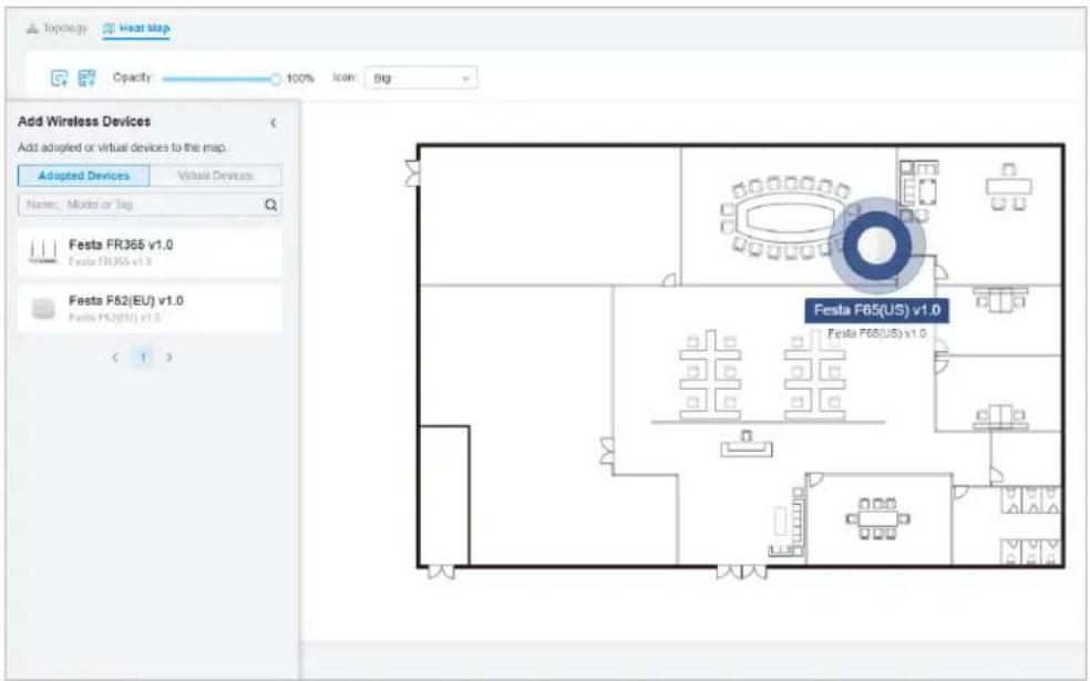
- Click 📋 on the upper left. Select a type of wall/obstacle area and then start drawing on the map. Left click to start and right click / hit Enter to end.
You can also edit the details parameters of the walls and obstacles, delete, and add walls. Adding correct obstacles will increase the accuracy of simulation results.
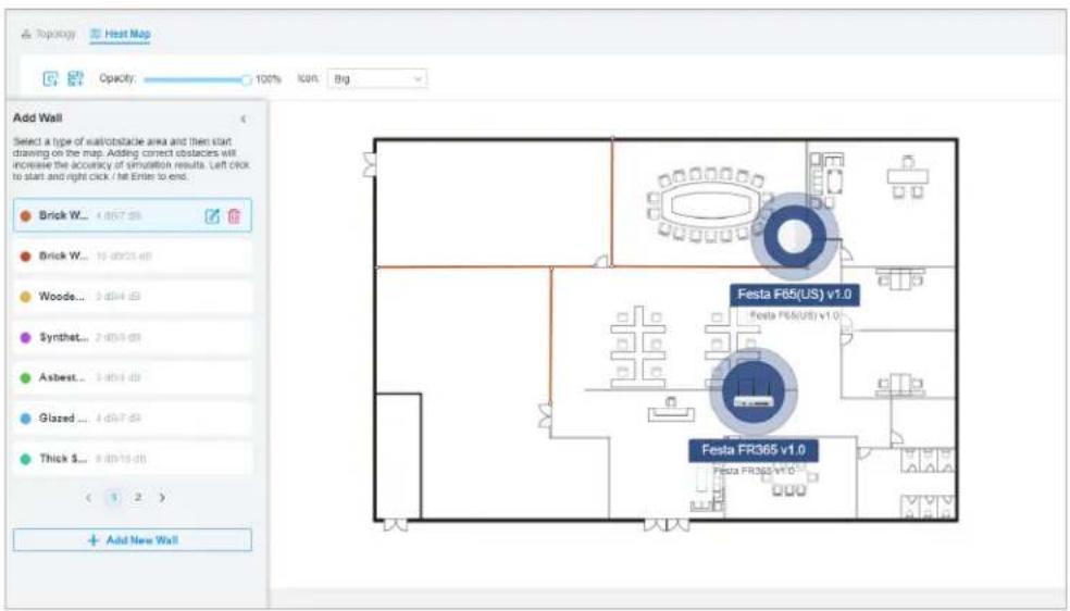
- Click to exit the editing status of the map.
Add Map Add Devices and Walls View Results

Note:
It is required to click Simulate to generate a new heat map after editing elements on the map.
Click Simulate to generate the heat map. You can adjust the receiver sensitivity, show signal strength, and view the simulation results according to your needs.
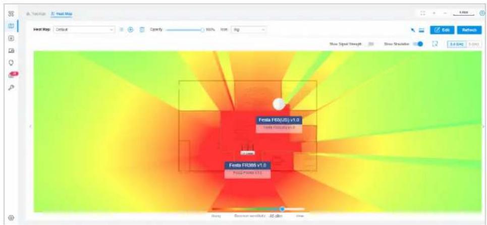
Show Signal Strength:

Enable the feature, and you can move the cursor to view the signal strength of a specific location.
Show Simulation:

Enable or disable the display of simulation results on the map.
2.4GHz
5GHz

Select 2.4GHz or 5GHz to view the simulation results of the band.

Click and follow the instruction to specify an area to view the signal strength and the corresponding percentage.
Adjust the receiver sensitivity, and the new settings will take effect after refreshing the simulation.
3 View the Statistics During Specified Period with Insights
In the Insights page, you can monitor the site history of portal authorizations and the VPN status.
3.1 Past Portal Authorizations
In Past Portal Authorization, a table lists all clients that passed the portal authorization before.
In the table, you can view the client's name, MAC address, authorization credential, authorization time, and the SSID/network it connected to. For detailed monitoring and management, refer to Manage Client Authentication in Hotspot Manager.

A search bar and a time selector are above the table for searching and filtering.
Search Name or MAC Address

Enter the client name or MAC address to search the clients.
Start date
- End date

Filter the clients based on Start Time.
Click the selector to open the calendar. Click a specific date twice in the calendar to display the clients authorized on the day. To display the clients authorized during a time range, click the start date and end date in the calendar.
3.2 VPN Status
In VPN Status, a table displays the existing VPN tunnels and corresponding information.
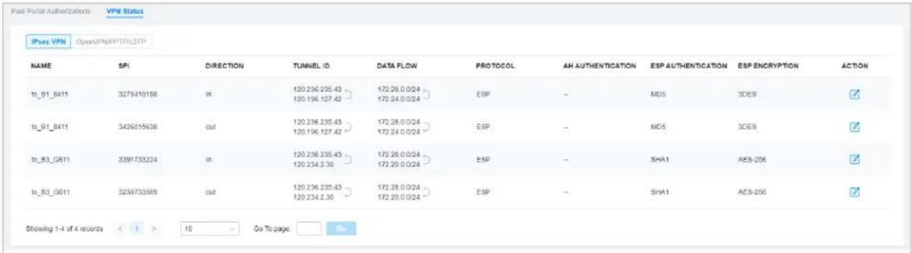
A tab is above the table for filtering. You can also click the icons for quick operation.
IPsec VPN
OpenVPNPPTPL2TP
Server

Click the tab to filter the routing information listed in the table.
When you select OpenVPN/PPTP/L2TP, you can further choose Server or Client.
| Click to configure the entry. | |
| (Only for OpenVPN/PPTP/L2TP) Filter the entries. | |
| (Only for OpenVPN/PPTP/L2TP) Click to terminate the VPN tunnel. | |
| (Only for OpenVPN/PPTP/L2TP) Click to choose more listed information to be displayed in the table. |
The listed information of IPsec VPN table is explained as follows.
Name Display the name of the IPsec VPN entry.
SPI Display the Security Parameter Index of VPN.
Direction Display the direction of the VPN process.
Tunnel ID
Display the local and remote IP address/name. The arrow indicates the traffic direction.
Data Flow Display local and remote subnet. The arrow indicates the direction.
Protocol Display the authentication and encryption protocol of the entry.
AH Authentication Display checksum algorithms of the entry.
ESP Authentication Display the algorithms for ESP authentication.
ESP Encryption Display the algorithms for ESP encryption.
| IPsec VPN | OpenVPN/PPTP/L2TP | Server | Client | |||||
| USER | INTERFACE | TYPE | LOCAL IP | REMOTE LOCAL IP | DNS | UPTIME | ACTION | |
| I2tpServer | WAN | L2TP Server (Client) | 192.168.11.1 | 192.168.11.2 | 8.8.8.8 | 3 h | ||
| pptpServer | WAN | PPTP Server (Client) | 192.168.10.1 | 192.168.10.2 | 8.8.8.8 | 3 h | ||
| Showing 1-2 of 2 records | < 1 > | 25 / page | Go To page: | Go |
The listed information of OpenVPN/PPTP/L2TP (Server) table is explained as follows (some information listed below is hidden by default). You can further filter the entries based on their type.
User Display the username of the remote user.
Interface Display the interface that the traffic goes through.
Type Display the connection type.
Local IP Display the local IP address of the VPN tunnel.
Remote Local IP Display the IP address of the remote user of the VPN tunnel.
DNS Display the DNS address of the VPN tunnel.
Download Pkts Display the amount of data downloaded as packets.
Download Bytes Display the amount of data downloaded as bytes.
Upload Pkts Display the amount of data uploaded as bytes.
Upload Bytes Display the amount of data uploaded as bytes.
Uptime Display the time duration that the VPN tunnel has been active.
| IFsec VPN OpenVPN/PPTP/L2TP Server Client | |||||||
| USER | INTERFACE | TYPE | LOCAL IP | REMOTE LOCAL IP | DNS | UPTIME ACTION | |
| I2tpServer | WAN | L2TP Server (Client) | 192.168.11.1 | 192.168.11.2 | 8.8.8.8 | 3 h | |
| pptpServer | WAN | PPTP Server (Client) | 192.168.10.1 | 192.168.10.2 | 8.8.8.8 | 3 h | |
| Showing 1-2 of 2 records < 1 > 25 / page Go To page: | |||||||
The listed information of OpenVPN/PPTP/L2TP (Client) table is explained as follows (some information listed below is hidden by default). You can further filter the entries based on their type.
Interface Display the interface that the traffic goes through.
Tunnel Display the name of the VPN client.
Type Display the connection type.
Remote Local IP Display the IP address of the remote user of the VPN tunnel.
DNS Display the DNS address of the VPN tunnel.
Download Pkts Display the amount of data downloaded as packets.
Download Bytes Display the amount of data downloaded as bytes.
Upload Pkts Display the amount of data uploaded as bytes.
Upload Bytes Display the amount of data uploaded as bytes.
Uptime Display the time duration that the VPN tunnel has been active.
4 View and Manage Logs
The controller uses logs to record the activities of the system, devices, users and administrators, which provides powerful supports to monitor operations and diagnose anomalies. In the Logs page, you can conveniently monitor the logs in Alerts and Events, and configure their notification levels in Notifications.
All logs can be classified from the following four aspects.
■ Occurred Hierarchies
Two categories in occurred hierarchies are Controller and Site, which indicate the log activities happened, respectively, at the controller level and in the certain site. Only Main Administrators can view the logs happened at the controller level.
■ Notifications
Two categories in notifications are Event and Alert, and you can classify the logs into them by yourself.
■ Severities
Three levels in severities are Error, Warning, and Info, whose influences are ranked from high to low.
- Contents
Four types in contents are Operation, System, and Device, which indicate the log contents relating to.
4.1 Alerts
Alerts are the logs that need to be noticed and archived specially. You can configure the logs as Alerts in Notifications, and all the logs configured as Alerts are listed under the Alerts tab for you to search, filter, and archive.
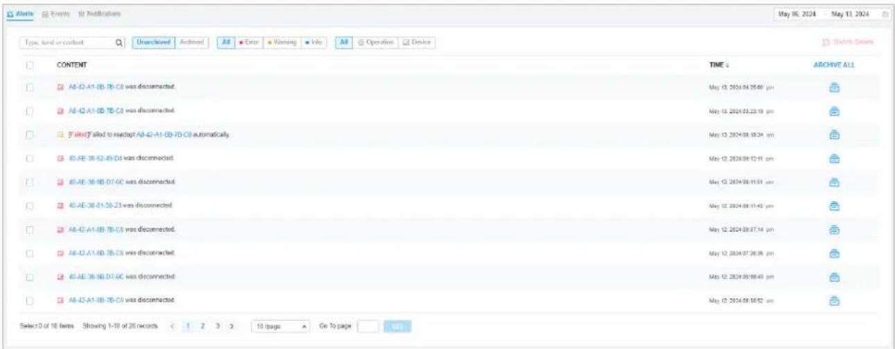
Type, level or content

Enter the content types, severity levels, or key words to search the logs.
| Unarchived | Archived | Click the tabs to filter the logs listed in the table. The two tabs can take effect simultaneously. |
| All | ErrorWarningInfo | Unarchived/Archived: Click the tab to filter the unarchived and archived logs. You can click and Archive All to archive a single log and all, respectively.All/Errors/Warnings/Info: Click All to display logs in both Error, Warning, and Info levels. Click Errors,Warnings or Info to display logs in Error or Warning levels only. |
| All | OperationDevice | All/Operation/Device: Click All to display all types of logs. Click Operation or Device to display the corresponding type of logs only. |
| Content | Displays the log types and detailed message. You can click the device name, client name to open its Properties window for detailed information. | |
| Time Displays when the activity happened. | ||
| Archive All Click to archive all unarchived logs. | ||
| Click to archive the log entry. | ||
| Batch Delete | Click and select the log types to delete the corresponding alert logs. Once deleted the archived alerts cannot be recovered. | |
4.2 Events
Events are the logs that can be viewed but have no notifications. You can configure the logs as Events in Notifications, and all the logs configured as Events are listed under the Events tab for you to search and filter.
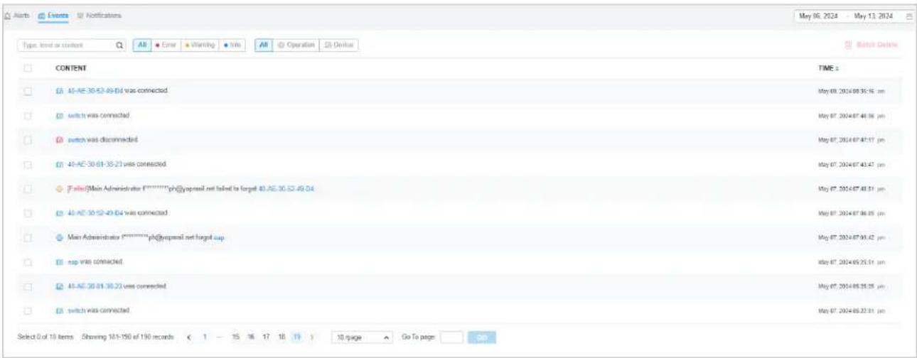
Type, level or content
Enter the content types, severity levels, or key words to search the logs.
| Batch Delete | Click and select the log types to delete the corresponding event logs. |
| All Errors Warnings Info | Click the tabs to filter the logs listed in the table. The two tabs can take effect simultaneously. |
| All Operation Device | All/Errors/Warnings/Info: Click All to display logs in both Error and Warning levels. Click Errors,Warnings or Info to display logs in the corresponding level only. All/Operation/Device: Click All to display all types of logs. Click Operation or Device to display the corresponding type of logs only. |
| Content Displays the log types and detailed message. You can click the device name, client name to open its Properties window for detailed information. | |
| Time Displays when the activity happened. | |
4.3 Notifications
In Notifications, you can find all kinds of activity logs classified by the content and specify their notification categories as Event and Alert for the current site. With proper configurations, the controller will send emails to the administrators when it records the logs.
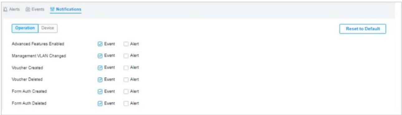
To specify the logs as Alert/Event, click the corresponding checkboxes of logs and click Apply. The following icons and tab are provided as auxiliaries.
| Reset to Default | Click to reset all notification configurations in the current site to the default. |
| Click the tabs to display the configurations of corresponding log types. | |
| □ Event □ Alert | Enable the checkboxes to specify the activity logs as Events/Alerts, and then the recorded logs will be displayed under the Events/Alerts tab. If both of them are disabled, the controller will not record the activity logs. |
| This icon appears when the configuration of a log is changed but has not been applied. Click it to reset the configuration of the log to the default. |
5 Monitor the Network with Tools
The controller provides many tools for you to analyze your network:
■ Network Check
Test the device connectivity via ping or traceroute.
Terminal
Open Terminal to execute CLI or Shell commands.

Note:
Firmware updates are required for earlier devices to support these tools.
5.1 Network Check
- In the Site view, go to Tools > Network Check.
- Configure the test parameters.
Network Check
Device Type:
EAP

Test:
Ping

Sources:
Please Select...

Destination Type:
Domain/IP Address

Domain/IP Address :

Advanced Test Settings
Packet Size:
32
(10-2000)
Count:
4
(1-100)

Devices which are already running commands shall not execute newly added commands. Output history of device with buffer space issues shall be automatically cleared
Device Type Select the type of device(s) to perform a test: EAP, Switch, or Gateway.
| Test | Choose the Ping or Traceroute tool to test the device connectivity. |
| Ping: Test the connectivity between the specified sources and destination, and measure the round-trip time. | |
| Traceroute: Display the route (path) the specified sources have passed to reach the specified destination, and measure transit delays of packets across an Internet Protocol network. | |
| Sources Select one or multiple devices to perform a test. | |
| Destination Type | Select the destination type and specify the Domain/IP Address or Client to ping. Client is unavailable in the traceroute test or when multiple AP devices perform the ping test. |
| Packet Size | When Test Type is Ping, specify the size of ping packets. |
| Count | When Test Type is Ping, specify the number of ping packets. |

Note:
• Devices which are already running commands shall not execute newly added commands.
- Output history of device with buffer space issues shall be automatically cleared.
3. Click Run to perform the test. You can view the test result in the Device Output section.



Click to download the test logs locally.
Zoom out and zoom in the display area.
5.2 Terminal
- In the Site view, go to Tools > Terminal.
- Configure the parameters.

Device Type Select the type of device(s) to test: EAP, Switch, or Gateway.
Sources Select one or multiple devices to test.
- Click Open Terminal. Now you can run CLI or Shell commands.


Click to download the test logs locally.

Zoom out and zoom in the display area.
Monitor and Manage the Clients
This chapter guides you on how to monitor and manage the clients through the Clients page using the clients table and the properties window and the Hotspot Manager system. To view clients that have connected to the network in the past, refer to View the Statistics During Specified Period with Insights. This chapter includes the following sections:
• 1 Manage Wired and Wireless Clients in Clients Page
• 2 Manage Client Authentication in Hotspot Manager
1 Manage Wired and Wireless Clients in Clients Page
1.1 Introduction to Clients Page
The Clients page offers a straight-forward way to manage and monitor clients. It displays all connected wired and wireless clients in the chosen site and their general information. You can also open the Properties window for detailed information and configurations.

| PENDING | The client has not passed the portal authentication and it is not connected to the internet. |
| AUTHORIZED | The client has been authorized and is connected to the internet. |
| CONNECTED | The client is connected to internet via non-portal network. |
| AUTHENTICATION-FREE | The client does not need to be authorized and it is connected to the internet. |
1.2 Using the Clients Table to Monitor and Manage the Clients
To quickly monitor and manage the clients, you can customize the columns and filter the clients for a better overview of their information. Also, quick operations and batch configuration are available.
■ Customize the Information Columns
Click ☐ next to the Action column and you have three choices: Default Columns, All Columns, and Customize Columns. To customize the information shown in the table, click the checkboxes of information type.
To change the list order, click the column head and the icon 🔊 appears for you to choose the ascending or descending order.
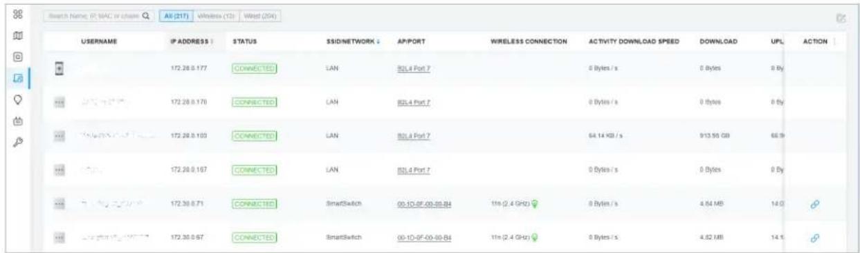
When this icon appears in the Wireless Connection column, it indicates the client is in the power-saving mode.
■ Filter the Clients
To search specific client(s), use the search box above the table. To filter the clients by their connection type, use the tab bars above the table. For wireless clients, you can further filter them by the frequency band and the type of connected wireless network.
| Search Name, IP, MAC or channel Q | Filter clients using the search box based on username, IP address, MAC address or channel. | ||
| All (2) | Wireless (1) | Wired (1) | Filter clients based on their connection type. |
| All (2) | 2.4 GHz (0) | 5 GHz (2) | (For wireless clients) Filter wireless clients based on the frequency band they are using. |
| All (2) | Users (0) | Guests (2) | (For wireless clients) Filter wireless clients based on the type of connected wireless network. Guests are clients connected to the guest network, which you can set during the Quick Setup, creating wireless networks, etc. |
■ Quick Operations
For quick operations on a single client, click the icons in the Action column. The available icons vary according to the client status and connection type.
| (With portal authentication enabled) Click to manually authorize the client that has not passed the portal authentication. | |
| (With portal authentication enabled) Click to unauthorized the client that has passed the portal authentication. | |
| (For wireless clients) Click to reconnect the wireless client to the wireless network. |
■ Multiple Select for Batch Configuration
To select multiple clients and add them to the Properties window, click 📄 on the upper-right and then check the boxes. When you finish choosing the clients, click Edit Selected and the chosen client(s) will be added to the Properties window for batch client configuration.
| USERNAME | IP ADDRESS | STATUS | SSID/NETWORK | APPORT | WIRELESS CONNECTION | ACTIVITY DOWNLOAD SPEED | DOWNLOAD | UPL | ACTION | MURLAN SELECT | |
| 12.0** | 172.26.0.177 | CONNECTED | LAN | 83L4 Port 7 | 0 Bytes / s | 0 Bytes | 0 By | ||||
| 17.1 (any) 0.5 | 172.26.0.170 | CONNECTED | LAN | 83L4 Port 7 | 0 Bytes / s | 0 Bytes | 0 By | ||||
| 9.1 (any) 0.5 (any) 3 | 172.26.0.163 | CONNECTED | LAN | 83L4 Port 7 | 54.14 KB / s | 913.55 GB | 66.9 | ||||
| 20.0% | 172.26.0.167 | CONNECTED | LAN | 83L4 Port 7 | 0 Bytes / s | 0 Bytes | 0 By |
1.3 Using the Properties Window to Monitor and Manage the Clients
In Properties window, you can view more detailed information about the connected client(s) and manage them. To open the Properties window, click the entry of a single client, or click the icon to select multiple clients for batch configuration. Use the following icons for the Properties window.
| Click to select multiple clients and add them to the Properties window for batch monitoring and management. | |
| Click to minimize the Properties window to an icon. To reopen the minimized Properties window, click ☐. | |
| Click to maximize the Properties window. You can also use the icon on pages other than the Clients page. | |
| Click to close the Properties window of the chosen client(s). Note that the unsaved configuration for the client(s) will be lost. | |
| The number on the lower-right shows the number of clients in the batch client configuration. |
Monitor and Manage a Single Client
■ Monitor a Single Client
After opening the Properties window of a single client, you can view the basic information, traffic statistics, and connection history under the Details tab.
Under the Details tab, Overview and Statistics displays the basic information and traffic statistics of the client, respectively. The listed information varies due to the client's status and connection type.
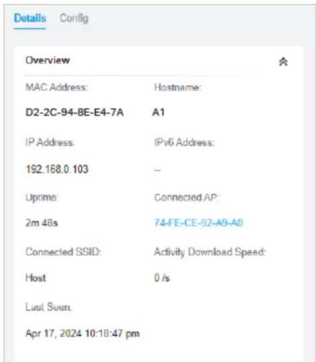
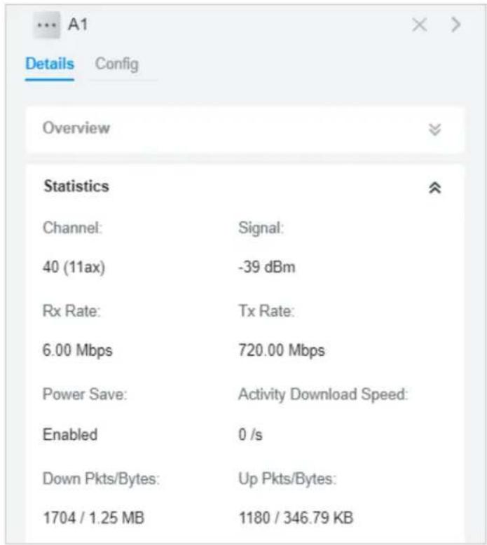
■ Manage a Single Client
In Config, you can configure the following parameters:
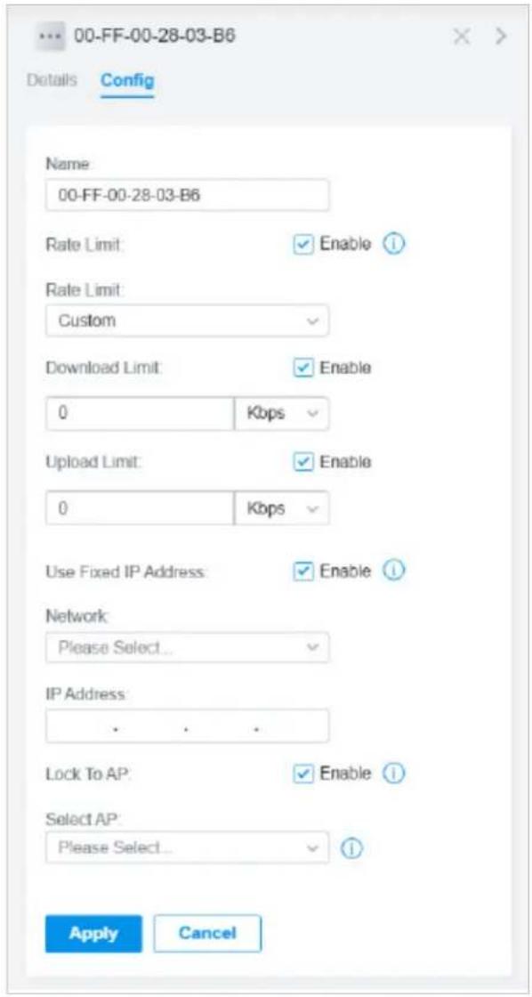
| Name | Specify the client's name to better identify different clients, and the name is used as the client's username in the table on the Clients page. |
| Rate Limit | Select an existing rate limit profile, create a new rate limit profile or customize the rate limit for the client.Custom: Specify the download/upload rate limit based on needs.Note: Rate Limit on this page is only available for the clients connected to the APs. To limit the rate of the clients connected to the gateway or switch, go to Bandwidth Control page. |
| Download/Upload Limit | Click the checkbox and specify the rate limit for download/upload for wireless clients using the voucher code(s). The value of the download and upload rate can be set in Kbps or Mbps. |
| Use Fixed IP Address | Click the checkbox to configure a fixed IP address for the client. With this function enabled, select a network and specify an IP address for the client. To view and configure networks, refer toConfigure Wired Networks.Note: A gateway is required for this function. Otherwise, you cannot set a fixed IP address for the client. |
| Lock To AP | Enable the function, and select one or multiple APs, then the client will be locked to the selected APs. This feature helps prevent a static client from roaming frequently between multiple APs. |
Monitor and Manage Multiple Clients
To manage multiple clients at the same time, click ☑, select multiple clients, and click Edit Selected. Then you can configure the following parameters under the Config tab.
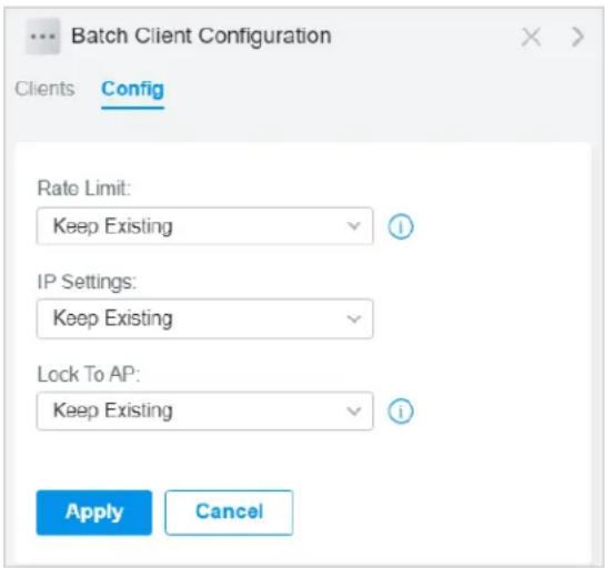
| Rate Limit | Select an existing rate limit profile, create a new rate limit profile or customize the rate limit for the clients.Keeping Existing: The rate limit of the chosen clients will remain their current settings.Custom: Specify the download/upload rate limit based on needs.Disabled: The rate limit of the chosen clients will be disabled.Note: Rate Limit on this page is only available for the clients connected to the APs. To limit the rate of the clients connected to the gateway or switch, go to Bandwidth Control page. |
| Download/Upload Limit | Click the checkbox and specify the rate limit for download/upload for wireless clients using the voucher code(s). The value of the download and upload rate can be set in Kbps or Mbps. |
| IP Setting | Keeping Existing: The IP setting of the chosen clients remains their current settings.Use DHCP: The IP addresses of the clients is automatically assigned by the DHCP server, such as the Layer 3 switch and the gateway.Use Fixed IP Address: Select a network and assign fixed IP addresses to the chosen clients manually. To view and configure networks, refer to Configure Wired Networks. Note that a gateway is required for this function. Otherwise, you cannot set fixed IP addresses for the chosen clients. |
| Lock To AP | Lock to AP helps prevent static clients from roaming frequently between multiple APs.Keeping Existing: Keep the current settings of the chosen clients Cooperative: Disable Lock to AP of the chosen clients.Enable: Enable Lock to AP, and select one or multiple APs, then the chosen clients will be locked to the selected APs. |
You can view their names and IP addresses in the Clients tab and remove client(s) from Batch Client Configuration by clicking ✗ in the Action column.
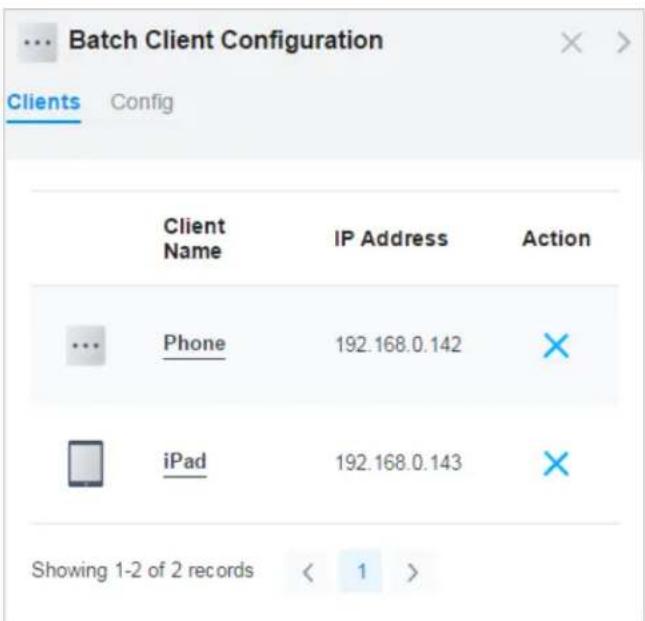
2 Manage Client Authentication in Hotspot Manager
Hotspot Manager is a portal management system for centrally monitoring and managing the clients authorized by portal authentication. The following four tabs are provided in the system for a easy and direct management.
Dashboard Monitor portal authorizations at a glance through different visualizations.
Authorized Clients View the records of the connected and expired portal clients.
Vouchers Create vouchers for Portal authentication, and view and manage the related information.
Form Auth Data Customize your survey contents and publish it to collect data.
Operators Create operator accounts for Hotspot management, view their information, and manage them.
To access the system, click Hotspot Manager from the drop-down list of Organization. To log out of the system, click the account icon 🔗 at the upper-right corner, then click Log Out.
2.1 Dashboard
In the dashboard, you can monitor portal authorizations at a glance through different visualizations.
To open the dashboard, click Hotspot Manager from the drop-down list of Organization and click Dashboard in the pop-up page. Specify the time period to view information on authentication type and hotspot type.
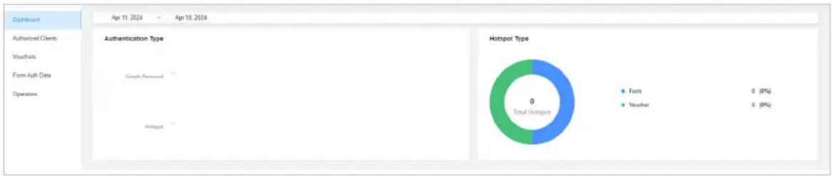
pie
| Authentication Type | Percentage (%) | | :--- | :--- | | Forms | 0 | | Voucher | 0 |2.2 Authorized Clients
The Authorized Clients tab is used to view and manage the clients authorized by portal system, including the expired clients and the clients within the valid period.
To open the list of Authorized Clients, click Hotspot Manager from the drop-down list of Organization and click Authorized Clients in the pop-up page. You can search certain clients using the search box, view their detailed information in the table, and manage them using the action column.
| Name | MAC ADDRESS | SSID/NETWORK | AUTHORIZED BY | DOWNLOAD | UPLOAD | START TIME | STATUS | EXPIRATION TIME | ACTION |
| 5C-1C-B9-17-9E-8F | 5C-1C-B9-17-9E-BF | EAP_test | No Authentication | 1.63GB | 51.67MB | Jan 12, 2021 10:06:54 pm | valid | Feb 11, 2021 10:06:54 pm | |
| android-f867b5d1b8190bf e | C8-F2-30-5A-FB-96 | EAP_test | No Authentication | 467.49MB | 28.72MB | Jan 12, 2021 08:49:49 pm | valid | Feb 11, 2021 08:49:49 pm | |
| OPPO-A8 | 20-82-8A-89-BE-BF | EAP_test | No Authentication | 615.13KB | 151.56KB | Jan 12, 2021 08:22:29 pm | valid | Feb 11, 2021 08:22:29 pm |


2.3 Vouchers
The Vouchers tab is used to create vouchers and manage unused voucher codes. With voucher configured and codes created, you can distribute the voucher codes generated by the controller to clients for them to access the network via portal authentication. For detailed configurations, refer to Portal.
Create vouchers
Follow the steps below to create vouchers for authentication:
-
Click Hotspot Manager from the drop-down list of Organization and click Vouchers in the pop-up page.
-
Click +Create Vouchers on the lower-left, and the following window pops up. Configure the following parameters and click Save.
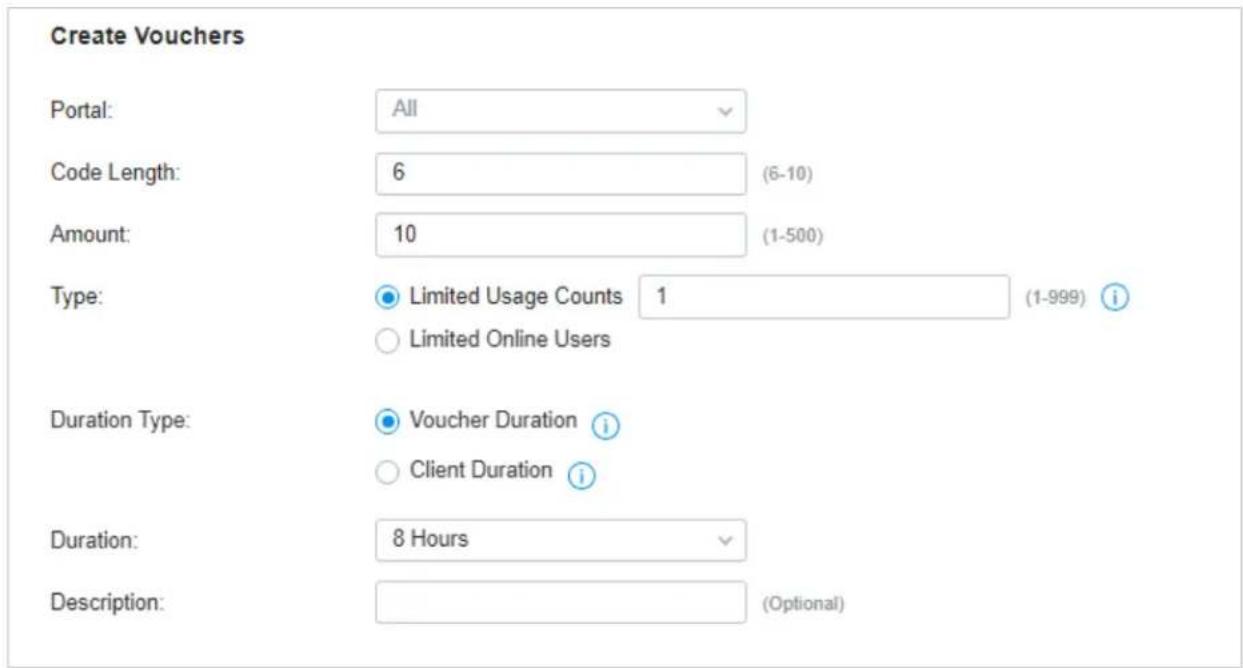
Portal Select the portal for which the vouchers will take effect.
Code Length Specify the length of the code(s) from 6 to 10 digits.
Amount Specify the number of voucher codes you want to create.
Type Select a type to limit the usage counts or the number of authorized users of a voucher code.
Limited Usage Counts: The voucher code can only be used for a limited number of times within its valid period.
Limited Online Users: The voucher code can be used for an unlimited number of times within its valid period, but only a limited number of wireless clients can access the network with this voucher code at the same time.
Duration Type Specify whether to limit the voucher duration or client duration.
Duration Select the valid period for the voucher code(s).
Description (optional) Enter notes for the created voucher code(s), and the input description is displayed in the voucher list under the voucher tab.
3. The voucher codes are generated and displayed in the table.
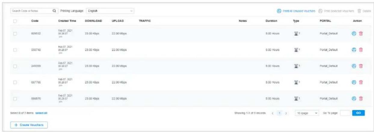
| The voucher code can be used for an unlimited number of times within its valid period, but only a limited number of wireless clients can access the internet with this voucher code at the same time. The number on the right shows the limited number of users. | |
| The voucher code can only be used for a limited number of times within its valid period. The number on the right shows the limited number of authentication times. |
- Print the vouchers. Click 📋 to print a single voucher, or click checkboxes of vouchers and click 📋 Print Selected Vouchers to print the selected vouchers. And you can click 📋 Print All Unused Vouchers to print all unused vouchers.
| 307690Valid for 8hLimited Usage Counts One | 084520Valid for 8hLimited Usage Counts One |
| 924665Valid for 8hLimited Usage Counts One | 232608Valid for 8hLimited Usage Counts One |
| 701945Valid for 8hLimited Usage Counts One | 473875Valid for 8hLimited Usage Counts One |
| 141716Valid for 8hLimited Usage Counts One | 999934Valid for 8hLimited Usage Counts One |
| 825813Valid for 8hLimited Usage Counts One | 180815Valid for 8hLimited Usage Counts One |
-
Distribute the vouchers to clients, and then they can use the codes to pass authentication.
-
To delete certain vouchers manually, click 📄 to delete a single voucher, or Delete to delete multiple voucher codes at a time.
2.4 Form Auth Data
The Form Auth Data tab is used to create and manage surveys. You can customize your survey contents and publish it to collect data.
Create Surveys
To create surveys, follow the steps below.
- Click Hotspot Manager from the drop-down list of Organization and click Form Auth Data in the pop-up page.
2. Click Create New Survey and the following window pops up.
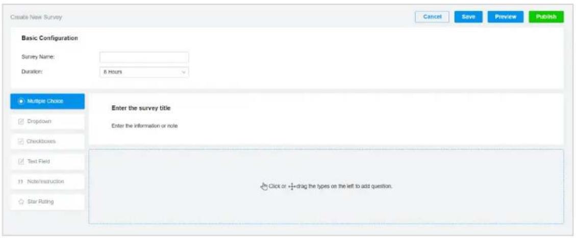
- Specify the survey name and duration, then customize the contents.
- Preview and save the settings or publish the survey.
- The surveys are created and displayed in the table. You can use icons for management and click for more management options.
| FORM AUTH NAME | PORTAL | CREATED TIME | RESPONSES | ACTION |
| Survey 1 Published | Not in Use | Aug 15, 2023 01:32:34 am | 0 | |
| Survey 2 Unpublished | Not in Use | Aug 15, 2023 01:33:18 am | 0 |
2.5 Operators
The Operators tab is used to manage and create operator accounts that can only be used to remotely log in to the Hotspot Manager system and manage vouchers and local users for specified sites. The operators have no privileges to create operator accounts, which offers convenience and ensures security for client authentication.
Create Operators
To create operator accounts, follow the steps below.
-
Click Hotspot Manager from the drop-down list of Organization and click Operators in the pop-up page.
-
Click Create Operator on the lower-left, and the following window pops up.
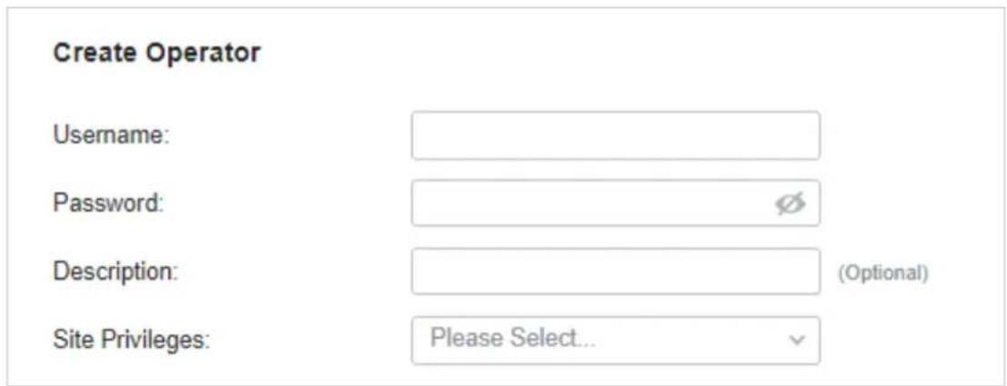
- Specify the username and password for the operator account.
- (Optional) Enter a description for identification.
- Select sites from the drop-down list of Site Privileges. Click Save.
- The operator accounts are created and displayed in the table. You can view the information of the create operator accounts on the page, search certain accounts through the name and notes, and use icons for management.

- Then you can use an operator account to log in to the Hotspot Manager system:
Visit the URL https://URL of the controller/ControllerID/login/#hotspot, and use the operator account to enter the hotspot manager system.
- Intended Readers
- Conventions
- More Information
- CONTENTS
- About this Guide
- Festa Cloud-Based Controller Solution Overview
- Get Started with Festa Cloud-Based Controller
- Manage and Configure Sites
- Manage, Configure, and Monitor Devices
- Configure the Network with the Festa Cloud-Based Controller
- Configure Wired Networks 94
- Configure Wireless Networks....125
- Network Security 136
- Transmission....149
- Configure VPN....157
- Create Profiles....187
- Authentication....194
- Services 202
- Monitor the Network
- Monitor and Manage the Clients
- Overview
- Core Components
- Festa Cloud-Based Controller
- Gateways
- Switches
- Access Points
- Set Up Your Festa Cloud-Based Controller
- Note:
- Navigate the Controller UI
- Overview
- Organization Management
- Global Search Feature
- My Account
- More Settings
- Global View
- The left-hand navigation bar in the Global View provides access to:
- ■ Site View
- ♥ 3 Configure Controller Settings
- System Settings
- Controller Settings
- ■ General Settings
- General Settings
- ■ User Interface
- ■ App-Side Device Notifications
- App-Side Device Notifications
- Manage Account
- Introduction to User Account and Role
- ■ User
- Role
- Create and Manage User Accounts
- Specify the parameters and click Invite.
- TP-Link ID
- Role Select a role for the created cloud user.
- Site Privileges Assign the site permission to the created cloud user.
- Create Sites
- Configuration
- ■ Create a site from scratch
- ■ Copy an existing site
- Create a Site View and Edit the Site Go into the Site
- Configure Site Settings
- Site Configuration
- Services
- Advanced Features
- Advanced Features
- Beacon Control
- Device Account
- Device Account
- Adopt Devices
- Adopt the Devices
- Set up the network.
- (Optional) Test the network.
- Connect to the Internet
- Introduction to the Devices Page
- ■ Customize the Column
- ■ Filter the Devices
- ■ Quick Operations
- ■ Batch Edit (for Switches and APs)
- Configure and Monitor the Gateway
- ① Note:
- Configure the Gateway
- Ports
- Config
- ■ General
- ■ Radios (for wireless gateways only)
- ■ WLANs
- ■ Services
- ■ Advanced
- ■ Manage Device
- ■ Common Settings
- Monitor the Gateway
- Monitor Panel
- Details
- Networks
- Clients
- Mesh (For wireless gateway only)
- Configure and Monitor Switches
- Configure Switches
- Port
- Name Status Prof ACTION
- - Override the Applied Profile
- - Configure a Mirroring Port
- - Configure a LAG
- Configuration Guidelines:
- LAG
- ■ VLAN Interface
- ■ Static Route
- Monitor Switches
- ■ Uplink (Only for the switch connected to a controller-managed gateway/switch in Connected status)
- Configure and Monitor APs
- Configure APs
- ■ IP Settings (Only for configuring a single device)
- Radios
- ■ Smart Antenna (For certain outdoor APs)
- Monitor APs
- ■ LAN (Only for devices in the Connected status)
- ■ Uplink (Wired) (Only for devices in the Connected status)
- ■ Uplink (Wireless) (Only for devices in the Connected status)
- ■ Radios (Only for devices in the Connected status)
- Mesh (Only for pending/connected/isolated devices supporting Mesh)
- Tips:
- Configure the Network with Festa Cloud-Based Controller
- Configure Wired Networks
- 1 Set Up an Internet Connection
- Select WAN Mode Configure WAN Connections (Optional) Configure Load Balancing
- WAN Mode
- WAN Settings Overrides
- Online Detection Interval
- - Set Up USB Modem Connection
- - Set Up IPv4 Connection
- Connection Type
- ■ Dynamic IP
- ■ Static IP
- ■ PPPoE
- L2TP
- ■ PPTP
- - Set Up IPv6 Connection
- ■ Dynamic IP (SLAAC/DHCPv6)
- ■ 6to4 Tunnel
- ■ Pass-Through (Bridge)
- - Set Up MAC Address
- Load Balancing
- Configure LAN Networks
- Configure the parameters according to the purpose for the network.
- ■ Interface
- Advanced DHCP Options
- Custom
- Configure IPv6
- Create New LAN
- Create a Network
- Create a Port Profile
- Assign the Port Profile to the Ports
- ! Note:
- Click + Create New Port Profile to load the following page, and configure the following parameters.
- Name Status Profile ACTION
- Configure Wireless Networks
- Set Up Basic Wireless Networks
- Create a WLAN Group
- Create Wireless Networks
- Apply the WLAN Group
- ■ None
- ■ WPA-Personal
- ■ WPA-Enterprise
- Create a WLAN Group Create Wireless Networks Apply the WLAN Group
- ■ Apply to a Single AP
- ■ Apply to APs in batch
- Advanced Settings
- Advanced Settings
- SSID Broadcast
- WLAN Schedule
- 802.11 Rate Control
- MAC Filter
- Multicast/Broadcast Management
- Network Security
- ACL
- ■ Gateway ACL
- ■ Switch ACL
- EAP ACL
- ■ Configuring Gateway ACL
- Set the States Type according to your needs:
- ■ Configuring Switch ACL
- ■ Configuring EAP ACL
- URL Filtering
- ■ Configuring Gateway Rules
- ■ Configuring EAP Rules
- Transmission
- Routing
- ■ Policy Routing
- Bandwidth Control
- Port Forwarding
- Configure VPN
- VPN
- IPsec
- OpenVPN
- ■ Site-to-Site VPN
- ■ Client-to-Site VPN
- Create a VPN Policy
- Select the purpose of the VPN
- Auto IPsec VPN
- Manual IPsec VPN
- Select the role of the gateway and VPN tunneling protocol
- ■ Configuring Site-to-Site VPN
- Create New VPN Policy
- Add Subnet
- Create
- Cancel
- Click Advanced Settings to load the following page.
- ■ Configuring Client-to-Site VPN
- VPN User
- Specify the parameters and click Create.
- Create New VPN User ⓘ
- Create Profiles
- Time Range
- Groups
- Batch Add
- Add from Client List
- Click Apply to save the entry.
- Rate Limit
- ♥ 7 Authentication
- Portal
- ■ Simple Password
- Hotspot
- - Voucher
- - Form Auth
- ■ Pre-Authentication Access
- ■ Authentication-Free Client
- Create New Portal
- - Voucher Portal
- - Form Authentication
- (Optional) Portal Customization
- Portal Customization
- (Optional) Access Control
- RADIUS Profile
- 8
- Services
- Dynamic DNS
- Before:
- After:
- Prerequisite:
- How Dynamic DNS works:
- SNMP
- SSH
- IPTV
- IGMP
- IPTV
- View the Status of Network with Dashboard
- Page Layout of Dashboard
- Topology Overview
- Explanation of Widgets
- ■ Most Active EAPs
- ■ Most Active SSIDs
- Alerts
- ■ Most Active Clients
- Page.
- Monitor the Network with Map
- Topology
- ■ Display of Branches
- ■ Diagram Size
- ■ Link Labels
- Heat Map
- 3) View simulation results.
- Go to Map > Heat Map and click ⭕ to add a new map. Then click Add.
- Add Map Add Devices and Walls You'll get
- Add Map Add Devices and Walls View Results
- View the Statistics During Specified Period with Insights
- Past Portal Authorizations
- VPN Status
- The listed information of IPsec VPN table is explained as follows.
- View and Manage Logs
- ■ Occurred Hierarchies
- ■ Notifications
- ■ Severities
- - Contents
- Alerts
- Events
- Notifications
- Monitor the Network with Tools
- Network Check
- Network Check
- Advanced Test Settings
- Click Run to perform the test. You can view the test result in the Device Output section.
- Terminal
- Manage Wired and Wireless Clients in Clients Page
- Introduction to Clients Page
- Using the Clients Table to Monitor and Manage the Clients
- ■ Customize the Information Columns
- ■ Filter the Clients
- ■ Multiple Select for Batch Configuration
- Using the Properties Window to Monitor and Manage the Clients
- Monitor and Manage a Single Client
- ■ Monitor a Single Client
- ■ Manage a Single Client
- Monitor and Manage Multiple Clients
- Manage Client Authentication in Hotspot Manager
- Dashboard
- Authorized Clients
- Vouchers
- Create vouchers
- The voucher codes are generated and displayed in the table.
- Form Auth Data
- Create Surveys
- Click Create New Survey and the following window pops up.
- Operators
- Create Operators
Brand : TP-LINK
Model : Festa FS352G
Category : Switch