
GA 4000ACIC-S - Pistolet de peinture automatique WAGNER - Free user manual and instructions
Find the device manual for free GA 4000ACIC-S WAGNER in PDF.


| Product Type | Automatic AirCoat spray gun for professional use |
| Weight | 880 g (31 oz) |
| Dimensions (Base Plate GA 4000ACIC-S) | Length: 129 mm (5.08 in), Width: 52 mm (2.04 in) |
| Max Fluid Pressure | 25 MPa (250 bar, 3625 psi) |
| Max Air Pressure | 0.6 MPa (6 bar, 87 psi) |
| Max Fluid Temperature | 80 °C (176 °F) |
| Max Air Temperature | 50 °C (122 °F) |
| Ambient Temperature Range | 5 °C to 40 °C (41 °F to 104 °F) |
| Fluid Connection | G1/4" internal thread |
| Air Connection | G1/8" internal thread |
| Sound Level | 82 dB(A) at 0.3 MPa air and 11 MPa fluid pressure |
| Materials (Paint-wetted Parts) | Stainless steel, carbide, POM, FPM, PTFE, UHMW-PE, EPDM |
| Spray Process | AirCoat (flat and round jet) |
| Nozzle Types | Interchangeable AirCoat nozzles ACF3000 (flat jet) and ACR3000 (round jet) |
| Air Cap Options | HV plus (blue) for high viscosity, LV plus (red) for low viscosity, LA plus (bronze), LV plus (blank) |
| Operating Mode | NC (no circulation) or C (circulation) with lock pin |
| Safety Certifications | ATEX II 2G X for potentially explosive areas (Directive 2014/34/EU) |
| Cleaning | Daily flushing with suitable solvent; external cleaning with moistened cloth |
| Maintenance | Regular checks of hoses, seals, and grounding; replace wearing parts as needed |
| Spare Parts Availability | WAGNER service sets and individual spare parts available (see spare parts list) |
Frequently Asked Questions - GA 4000ACIC-S WAGNER
User questions about GA 4000ACIC-S WAGNER
0 question about this device. Answer the ones you know or ask your own.
Ask a new question about this device
Download the instructions for your Pistolet de peinture automatique in PDF format for free! Find your manual GA 4000ACIC-S - WAGNER and take your electronic device back in hand. On this page are published all the documents necessary for the use of your device. GA 4000ACIC-S by WAGNER.
USER MANUAL GA 4000ACIC-S WAGNER
Translation of the Original Operating Manual
For professional use.
Always follow the information in this manual, particularly the safety instructions and the warning instructions. Store the manual in a safe place.
Version 05/2018
GA 4000ACIC-S
GA 4000ACIC-R
AirCoat
Automatic spray gun
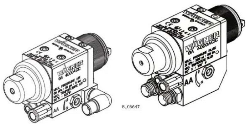
Table of Contents
1 ABOUT THESE INSTRUCTIONS 6
1.1 Preface 6
1.2 Warnings, Notices and Symbols in these Instructions 6
1.3 Languages 7
1.4 Abbreviations 7
1.5 Terminology for the Purpose of this Manual 8
2 CORRECT USE 9
2.1 Device Type 9
2.2 Type of Use 9
2.3 For Use in Potentially Explosive Areas 9
2.4 Processible Working Materials 9
2.5 Misuse 9
3 IDENTIFICATION
3.1 Explosion Protection Identification 10
3.2 Identification "X" 10
3.3 Type plate 11
4 BASIC SAFETY INSTRUCTIONS
4.1 Safety Instructions for the Operator 12
4.1.1 Electrical Devices and Equipment 12
4.1.2 A Safe Work Environment 13
4.1.3 Personnel Qualifications 13
4.2 Safety Instructions for the Personnel 14
4.2.1 Personal Safety Equipment 14
4.2.2 Safe Handling of WAGNER Spray Devices 15
4.2.3 Grounding the Unit 15
4.2.4 Product hoses 16
4.2.5 Cleaning and Flushing 17
4.2.6 Touching Hot Surfaces 18
4.2.7 Maintenance and Repair 18
4.2.8 Protective and Monitoring Equipment 18
5 DESCRIPTION
5.1 Components
5.2 Functional Description 20
5.2.1 Mode of Operation 20
5.2.2 Mode "NC" and "C" 21
5.2.3 Spraying procedure 22
5.3 Included Items 23
5.3.1 Type description 23
5.3.2 Overview 24
5.3.3 Standard variant 25
5.3.4 Supplementary components 25
5.4 Data 28
5.4.1 Materials of Paint-wetted Parts 28
5.4.2 Technical data 28
5.4.3 Measurements and connections 29
6 COMMISSIONING 31
6.1 Training of Assembly/Commissioning Personnel 31
6.2 Storage Conditions 31
6.3 Installation Conditions 31
6.4 Installation and Connection 31
6.4.1 Typical AirCoat spraying system 32
6.4.2 Ventilation of the Spray Booth 32
6.4.3 Air Supply Lines 32
6.4.4 Product supply lines 33
6.5 Grounding 33
6.6 Safety Checks 33
6.7 Lacquer Preparations 33
6.7.1 Viscosity conversion table 34
6.8 Commissioning 35
6.8.1 Preparation Before Commissioning 35
6.8.2 Commissioning 35
6.8.3 Verifying a Safe Operational Condition 35
7 OPERATION 36
7.1 Training the Operating Personnel 36
7.2 Tasks 36
7.2.1 Starting to Spray with the AirCoat 36
7.2.2 Adjusting the spray pattern 37
7.2.3 Pressure Relief/Work Interruption 37
7.2.4 Changing AirCoat nozzle 38
7.2.5 Cleaning AirCoat nozzle 38
7.2.6 Eliminating Nozzle Clogging 39
7.2.7 Replacing nozzle insert of round jet nozzle 40
8 CLEANING AND MAINTENANCE 41
8.1 Cleaning 41
8.1.1 Cleaning Personnel 41
8.1.2 Flushing and Cleaning the Gun 41
8.2 Maintenance 42
8.2.1 Maintenance Personnel 42
8.2.2 Maintenance Instructions 42
8.2.3 Safety Checks 43
8.2.4 Replacing the paint hose 44
8.2.5 Replacing the nozzle seal 44
8.2.6 Replacing the Sealing Fitting of the Round Jet Nozzle 45
9 TROUBLESHOOTING AND RECTIFICATION 46
10 REPAIR WORK 47
10.1 Repair Personnel 47
10.2 Repair Notes 47
10.3 Replacing parts of the gun body 48
10.3.1 Disassembly of GA 4000ACIC 48
10.3.2 Packing insert GA 4000AC (RP) 50
10.3.3 Assembly of GA 4000ACIC 52
11 FUNCTION TEST AFTER REPAIR WORK 54
12 DISPOSAL 54
13 ACCESSORIES 55
13.1 AirCoat Nozzles ACF3000 55
13.2 AirCoat Nozzles ACF3000 S2 (4 pieces) 57
13.3 Round jet nozzle attachment 57
13.3.1 RXX Nozzle inserts 58
13.3.2 Nozzle screw joint, complete 58
13.4 Hoses 58
13.5 Miscellaneous 59
14 SPARE PARTS 60
14.1 How can spare parts be ordered? 60
14.2 Spare Parts List for GA 4000ACIC 61
14.3 Service sets and spare parts groups 63
14.4 Packing insert GA 4000AC (RP) 63
14.5 Sealing Set GA 4000 Packing RP and RP Special 64
15 DECLARATION OF CONFORMITY 65
15.1 EU Declaration of Conformity 65
1 ABOUT THESE INSTRUCTIONS
1.1 PREFACE
The operating manual contains information about safely operating, maintaining, cleaning and repairing the device.
The operating manual is part of the device and must be available to the operating and service personnel.
The device may only be operated by trained personnel and in compliance with this operating manual.
Operating and service personnel should be instructed according to the safety instructions.
This equipment can be dangerous if it is not operated according to the instructions in this operating manual.
1.2 WARNINGS, NOTICES AND SYMBOLS IN THESE INSTRUCTIONS
Warning instructions in this manual highlight particular dangers to users and to the device and state measures for avoiding the hazard. These warning instructions fall into the following categories:

DANGER
Immediate risk of danger.
Non-observance will result in death or serious injury.

WARNING
Potential risk.
Non-observance may result in death or serious injury.

CAUTION
Potentially hazardous situation.
Non-observance may result in minor injury.

NOTICE
Potentially hazardous situation.
Non-observance may result in damage to property.
Notice
Provides information about particular characteristics and how to proceed.
Explanation of warning notice:

LEVEL OF DANGER
This notice warns you of a hazard!
Possible consequences of not observing the warning notice.
→ The measures for preventing the hazard and its consequences.

1.3 LANGUAGES
The operating manual is available in the following languages:
| Language Order | No. Language Order No. | ||
| German 2312955 | Swedish 2316798 | ||
| English 2312956 | Russian 2327992 | ||
| French 2312957 | Hungarian 2364607 | ||
| Italian 2312958 -- | |||
| Spanish 2312959 | --- | ||
Additional languages on request or at: www.wagner-group.com
1.4 ABBREVIATIONS
| Order No. | Order number |
| ET | Spare part |
| K | Marking in the spare parts lists |
| Pos | Position |
| Stk | Number of pieces |
| SW | Wrench size (tool) |
| TX | Torx size (tool) |
| RP | Replaceable Packing (replaceable packing) |
| PTFE | Polytetrafluorethylene (PTFE) |
| GF | Fiber optics |
| PE Polyethylene | |
| UWMW-PE | Ultra-high molecular polyethylene |
| FPM | Fluoropolymer rubber (Viton) |
| POM | Polyoxymethylene (Acetal) |
| PA Polyamide | |
1.5 TERMINOLOGY FOR THE PURPOSE OF THIS MANUAL
| Cleaning | |
| Cleaning Manual cleaning | of devices and device parts with cleaning agent |
| Flushing Internal flushing | of paint-wetted parts with compressed air |
| Product pressure generator | Pump or pressure tank |
| Personnel qualifications | |
| Trained person is instructed in the tasks assigned to him/her, the potential risks associated with improper behavior as well as the necessary protective devices and measures. | |
| Electrically trained person | Is instructed by an electrician about the tasks assigned to him/her, the potential risks associated with improper behavior as well as the necessary protective devices and measures. |
| Electrician Can assess the work assigned to him/her and detect possible hazards based on his/her technical training, knowledge and experience in relevant provisions. | |
| Skilled person in accordance with TRBS 1203 (2010/Revision 2012) | A person, who, based on his/her technical training, experience and recent vocational experience, has sufficient technical knowledge in the areas of explosion protection, protection from pressure hazards and electric hazards (if applicable) and is familiar with the relevant and generally accepted rules of technology so that he/she can inspect and assess the status of devices and coating systems based on workplace safety. |
2 CORRECT USE
2.1 DEVICE TYPE
Automatic gun for automatic coating of work pieces.
2.2 TYPE OF USE
The gun is suitable for atomizing liquid products, particularly coating products, using the AirCoat process.
WAGNER explicitly prohibits any other use!
The device may only be operated under the following conditions:
→ Use the device only to work with the products recommended by WAGNER.
→ Only operate the device as a whole.
→ Do not deactivate safety fixtures.
→ Use only WAGNER original spare parts and accessories.
→ The operating personnel must be trained on the basis of this operating manual.
→ Follow the instructions in the operating manual.
2.3 FOR USE IN POTENTIALLY EXPLOSIVE AREAS
The device is suitable for use in potentially explosive areas as defined in Directive 2014/34/EU, (see Explosion protection marking Chapter 3.1).

2.4 PROCESSIBLE WORKING MATERIALS
Top-coat lacquers, primer paints, corrosion protection, textured lacquers, lyes, staining solvents, clear lacquers, separating agents, etc. with a solvent or water base. If you want to spray working materials other than the aforementioned, contact a WAGNER representative.
When operating the device with a coating product with a temperature of >43 °C; 109.4 °F, identify the device with a warning label that says "Warning - hot surface" according to Chapter 4.2.6.
Note:
Contact your local WAGNER dealer and the lacquer manufacturer if you encounter application problems.
2.5 MISUSE
Misuse can lead to physical injury and/or property damage! Special attention must be paid that:
→ no dry coating products, e.g. powder are processed;
→ no food, medicine or cosmetics are processed.
3 IDENTIFICATION
3.1 EXPLOSION PROTECTION IDENTIFICATION
As defined in the Directive 2014/34/EU (ATEX), the device is suitable for use in potentially explosive areas.
Device type: AirCoat automatic gun
Manufacturer: Wagner International AG
9450 Altstätten
Switzerland

CEEx II 2GX
CE European Communities
Ex Symbol for explosion protection
II Device class II
2 Category 2 (zone 1)
G Ex-atmosphere gas
X Special notice

3.2 IDENTIFICATION "X"
The maximum surface temperature corresponds to the permissible product temperature. This and the permissible ambient temperature can be found in the "Technical Data" chapter.
Safe Handling of WAGNER Spray Devices
Mechanical sparks can form if the device comes into contact with metal.
In an explosive atmosphere:
→ Do not knock or push the device against steel or rusty iron.
→ Do not drop the spray gun.
→ Use only tools that are made of a permitted material.
Ignition temperature of the coating product
→ Ensure that the ignition temperature of the coating product is above the maximum surface temperature.
Medium supporting atomizing
→ To atomize the product, use only weakly oxidizing gases, e.g., air.
Cleaning
If there are deposits on the surfaces, the device may form electrostatic charges. Flames or sparks can form during discharge.
→ Remove deposits from the surfaces to maintain conductivity.
3.3 TYPE PLATE
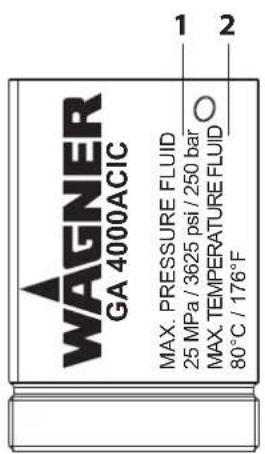
B 06637


| Pos | Designation |
| 1 | Maximum product pressure |
| 2 | Maximum product temperature |
| 3 | Serial number |
| 4 | Maximum air temperature |
| 5 | Maximum air inlet pressure |
4 BASIC SAFETY INSTRUCTIONS
4.1 SAFETY INSTRUCTIONS FOR THE OPERATOR
→ Keep this operating manual at hand near the device at all times.
→ Always follow local regulations concerning occupational safety and accident prevention.
4.1.1 ELECTRICAL DEVICES AND EQUIPMENT
Electric shock hazard!
Danger to life from electric shock.
→ Prepare device in accordance with the local safety requirements with regard to the operating mode and ambient influences.
→ May only be maintained by skilled electricians or under their supervision. With open housings, the mains voltage poses a danger.
→ Operate device in accordance with the safety regulations and electrotechnical regulations.
→ Must be repaired immediately in the event of problems.
→ Decommission if it poses a hazard or is damaged.
→ Must be de-energized before work is commenced. Inform personnel about planned work. Observe electrical safety regulations.
→ Ground all devices to a common grounding point.
→ Only operate the device with a properly installed socket with a protective ground wire connection.
→ Keep liquids away from electrical devices.


4.1.2 A SAFE WORK ENVIRONMENT
Hazard due to dangerous fluids or vapors!
Severe or fatal injuries due to explosion hazard or inhalation, swallowing or contact with the skin or eyes.
→ Ensure that the floor in the working are is static dissipative in accordance with EN 61340-4-1 (resistance must not exceed 100 MΩ)
→ Paint mist extraction systems/ventilation systems must be fitted on site according to local regulations.
→ Make sure that the ground connection and potential equalization of all system parts are reliable and continuous and can withstand the expected stress (e.g. mechanical stress, corrosion).
→ Ensure that product/air hoses that have been adapted to the working pressure are used.
→ Ensure that personal protective equipment (see Chapter 4.2.1) is available and is used.
→ Ensure that all persons within the working area wear static dissipative shoes. Footwear must comply with EN 20344. The measured insulation resistance must not exceed 100 MΩ
→ Protective clothing, including gloves, must comply with EN 1149-5. The measured insulation resistance must not exceed 100 MΩ
→ Ensure that there are no ignition sources such as naked flames, sparks, glowing wires, or hot surfaces in the vicinity. No smoking.
→ Ensure that the pipe joints, hoses, equipment parts and connections are permanently, technically leak-proof:
– Periodic preventative maintenance and service (replacing hoses, checking tightness of connections, etc.).
- Regular monitoring of leaks and defects via visual inspection and odor testing, e.g. daily before commissioning, at the end of work or weekly.
→ In the event of defects, immediately bring the device or system to a stop and arrange to have repairs carried out immediately.
4.1.3 PERSONNEL QUALIFICATIONS
Hazard due to incorrect use of device!
Risk of death due to untrained personnel.
→ Ensure that the operating personnel has been instructed by the operator in accordance with the operating manual and the operating instructions. The device must only be operated, maintained and repaired by trained personnel. Refer to the operating instructions for information about the required personnel qualifications.


4.2 SAFETY INSTRUCTIONS FOR THE PERSONNEL
→ Always follow the information in this manual, particularly the safety instructions and the warning instructions.
→ Always follow local regulations concerning occupational safety and accident prevention.
→ In electrostatics applications: Persons belonging to a risk group according to EMF guideline 2013/35/EU (e.g., carriers of active implants), must not enter the high-voltage area.

4.2.1 PERSONAL SAFETY EQUIPMENT
Hazard due to dangerous fluids or vapors!
Serious or fatal injuries due to inhalation, swallowing or contact with the skin or eyes.
→ When preparing or working with lacquer and when cleaning the device, follow the working instructions of the manufacturer of the lacquers, solvents, and cleaning agents being used.
→ Take the specified protective measures. In particular wear safety goggles, protective clothing and gloves, as well as hand protection cream if necessary.
→ Use a mask or breathing apparatus if necessary.
→ For sufficient health and environmental safety: Operate the device in a spray booth or on a spraying wall with the ventilation (extraction) switched on.
→ Wear suitable protective clothing when working with hot products.

4.2.2 SAFE HANDLING OF WAGNER SPRAY DEVICES
Hazard due to injection of lacquer or flushing agent into the skin!
The spray jet is under pressure and can cause dangerous injuries. Avoid injection of lacquer or flushing agents:
→ Never point the spray gun at people.
→ Never reach into the spray jet.
→ Before any work on the device, in the event of work interruptions and malfunctions:
- Switch off the energy/compressed air supply.
- Relieve the pressure from the spray gun and device.
- Secure the spray gun against actuation.
- Disconnect the control unit from the mains.
- In the event of functional faults: remedy the fault as described in the "Troubleshooting" chapter.
→ If necessary or at least every 12 months, the liquid ejection devices must be checked for safe working conditions by an expert (e.g. WAGNER Service Technician) in accordance with the guidelines for liquid ejection devices (DGUV [German Statutory Accident Insurance] regulation 100-500 section 2.29 and 2.36).
- For shut down devices, the examination can be suspended until the next start-up.
→ Carry out the work steps as described in the "Pressure relief" chapter:
- if pressure relief is required,
- if the spraying work is interrupted or stopped.
– before the device is cleaned on the outside, checked, or serviced,
– before the spray nozzle is installed or cleaned.

In the event of skin injuries caused by lacquer or flushing agents:
→ Note the lacquer or flushing agent that you have been using.
→ Consult a doctor immediately.
4.2.3 GROUNDING THE UNIT
Hazard due to electrostatic charge!
Explosion hazard and damage to the device.
Friction, flowing liquids and air or electrostatic coating processes create charges. Flames or sparks can form during discharge.
Correct grounding of the entire spraying system prevents electrostatic charges.
→ Ensure that all devices and tanks are grounded before each spraying process.
→ Ground the work pieces to be coated.
→ Ensure that all persons inside the working area are grounded, e.g., that they are wearing static dissipative shoes.
→ The spray substance supply (spray substance tank, pump, etc.) must be grounded.


4.2.4 PRODUCT HOSES
Hazard due to bursting of product hose!
The product hose is under pressure and may cause dangerous injuries.
→ Ensure that the hose material is chemically resistant to the sprayed products and the flushing agents used.
→ Ensure that the product hose and the fittings are suitable for the pressure generated.
→ Ensure that the following information can be seen on the high-pressure hose:
- manufacturer,
– permissible operating pressure, - date of manufacture.
→ Make sure that the hoses are laid only in suitable places. Hoses should not be laid in the following places under any circumstances:
- in high-traffic areas,
-on sharp edges, - on moving parts or
- on hot surfaces.
→ Ensure that the hoses are never run over by vehicles (e.g., fork lift trucks), or that the hoses are never put under pressure from the outside in any other way.
→ Ensure that the hoses are never kinked. Observe maximum bending radii.
→ Ensure that no work is ever performed with a damaged hose.
→ Make sure that the hoses are never used to pull or move the equipment.
→ The electrical resistance of the product hose, measured at both valves, must be less than 1 MΩ
→ Suction hoses may not be subjected to pressure.

4.2.5 CLEANING AND FLUSHING
Hazard due to cleaning and flushing!
Explosion hazard and damage to the device.
→ Preference should be given to non-ignitable cleaning and flushing agents.
→ When carrying out cleaning work with flammable cleaning agents, make sure that all equipment and resources (e.g., collection tank, funnel, transport cart) are conductive or static dissipative and grounded.
→ Observe the specifications of the lacquer manufacturer.
→ Ensure that the flash point of the cleaning agent is at least 15 K above the ambient temperature or that cleaning is undertaken at a cleaning station with technical ventilation.
→ Explosive gases are produced when aluminum comes into contact with halogenated hydrocarbons. To clean aluminum, do not use liquids containing halogenated hydrocarbons.
→ Take measures for workplace safety (see Chapter 4.1.2).
→ When commissioning or emptying the device, please note that:
- depending upon the coating product used, - depending on the flushing agent (solvent) used. In explosive mixture may temporarily exist inside the lines and components of equipment.
→ Only electrically conductive tanks may be used for cleaning and flushing agents.
→ The tanks must be grounded.
An explosive gas/air mixture forms in closed tanks.
→ Never spray into a closed tank when using solvents for flushing.


External Cleaning
When cleaning the exterior of the device or its parts, also observe the following:
→ Relieve the pressure from the device.
→ De-energize the device electrically.
→ Disconnect the pneumatic supply line.
→ Use only moistened cloths and brushes. Never use abrasive agents or hard objects and never spray cleaning agents with a gun. Cleaning the device must not damage it in any way.
→ Ensure that no electrical component is cleaned with or even immersed in solvent.

Hazard due to hot surfaces because of hot coating products!
Risk of burn injuries.
→ Only touch hot surfaces if you are wearing protective gloves.
→ When operating the device with a coating product with a temperature of >43 °C; 109 °F:
- Identify the device with a warning label "Warning – hot surface".
Order No.
9998910 Instruction label
9998911 protection label
Note: Order the two stickers together.

4.2.7 MAINTENANCE AND REPAIR
Hazard due to improper maintenance and repair!
Danger to life and equipment damage.
→ Only a WAGNER service center or a suitably trained person may carry out repairs and replace parts.
→ Do not change or modify the device; if change is necessary, contact WAGNER.
→ Only repair and replace parts that are listed in Chapter 13 and Chapter 14 that are assigned to the unit.
→ Do not use any defective components.
→ Exclusively use accessories listed in Chapter 13 and that are assigned to the unit.
→ Before all work on the device and in the event of work interruptions:
– Switch off the energy and compressed air supply.
- Relieve the pressure from the spray gun and device.
- Secure the spray gun against actuation.
→ Observe the operating and service manual for all work.
4.2.8 PROTECTIVE AND MONITORING EQUIPMENT
Hazard due to removal of protective and monitoring equipment!
Danger to life and equipment damage.
→ Protective and monitoring equipment must not be removed, modified or rendered unusable.
→ Regularly check for perfect functioning.
→ If defects are detected on protective and monitoring equipment, the system must not be operated until these defects are remedied.
5 DESCRIPTION
5.1 COMPONENTS


| Pos | Designation |
| A | Gun head |
| B | Spray gun body |
| C | Tension sleeve drive |
| D | Base plate |
| E | Atomizing air connection (blue) |
| F | Union nut |
| G | Air cap (blue, red or bronze) |
| H | Nozzle |
| I | Standard holder |
| J | Connecting fitting (product) |
| K | Connecting fitting (product) |
| L | Connection for control air (red) |
| M | Shaping air throttle |
| N | Product channel lock pin |
The device consists of a gun head (A), gun body (B), drive (C) and base plate (D). The air cap (G), appropriate nozzle (H) and various parts for sealing and fastening are attached to the gun head (A). The product valve and packing are housed in the gun head (A). The clamping mechanism for the packing is installed in the gun body (B). The gun body also serves as a connecting piece between the drive (C) and the gun head (A). The drive (C) consists a diaphragm and a pressure spring for the product valve. The base plate (D) contains all connections (E, J, K) and a shaping air throttle (M). It can be used to connect the gun to the corresponding reciprocator or gun holder.
5.2 FUNCTIONAL DESCRIPTION
5.2.1 MODE OF OPERATION
Diagram:
SA = Shaping air
AA = Atomizing air
CA = Control air
M = Product
C = Circulation

flowchart
graph TD
    M --> A["Valve"]
    A --> B["Nozzle"]
    C --> A
    B --> C
    A --> C
    A --> D["Valve"]
    D --> E["SA"]
    D --> F["AA"]
    D --> G["CA"]
    style A fill:#f9f,stroke:#333
    style B fill:#ccf,stroke:#333
    style C fill:#cfc,stroke:#333
    style D fill:#fcc,stroke:#333
    style E fill:#cff,stroke:#333
    style F fill:#ffc,stroke:#333
    style G fill:#cfc,stroke:#333
Open:
The piston in the drive is charged with control air and moves toward the rear. This ensures that the air valve which releases the shaping and atomizing air is opened first. The product valve is then opened with a mechanical delay. In this position, the pressurized coating product is applied to the work piece.
Close:
The piston is relieved, and the product valve closes due to the pressure spring which presses against the product valve tappet. The air valve is then closed, again with a spring force and mechanical delay.
Additional functions:
The shaping air throttle is used to regulate the shaping air volume, while the atomizing air is adjusted via an external pressure regulator. The two air streams do not flow separately until they are downstream of the air valve, so that the pressure of the shaping air corresponds roughly to that of the atomizing air and so that they influence each other during adjustment.
The product connections and the paint channels in the base plate are arranged so that several guns can run in circulation mode.
5.2.2 MODE "NC" AND "C"

DANGER
Spurting out of liquids with high pressure!
Danger to life and equipment damage.
→ For the operating mode NC (no product circulation), the spray gun may only be connected if the lock pin is installed.

5.2.2.1 MODE "NC" WITHOUT PRODUCT CIRCULATION
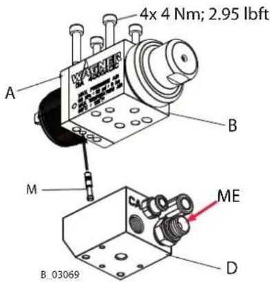
In this mode of operation, the left or the right product channel in the gun head (A) is locked by the lock pin (M) and the product entrance (ME) is always on the opposite side.
5.2.2.2 MODE "C" WITH PRODUCT CIRCULATION
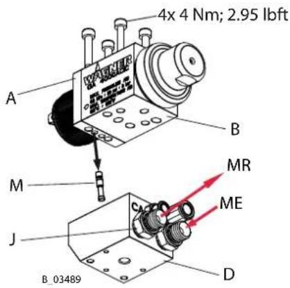
In this mode of operation, the lock pin (M) must be removed from the left or right product channel in the gun head (A). Screw on additional connection fitting (J). The product entrance (ME) and the product return (MR) are freely selectable in this mode of operation.
5.2.3 SPRAYING PROCEDURE
5.2.3.1 AIRCOAT FLAT SPRAYING PROCEDURE
For normal applications with the AirCoat flat jet process, the spray product is atomized at a pressure of 3-12 MPa; 30-120 bar; 435-1740 psi. For normal applications, a soft, optimum spray jet is achieved with help of the atomizing air, which has a pressure of 0.05-0.25 MPa; 0.5-2.5 bar; 7.2-36 psi. This eliminates most overlapping problems in the peripheral zones. The shaping air allows the width of the spray jet to be increased or decreased.

Advantages:
– Large application volume.
– Low fogging tendency.
- Good finish.
– High-viscosity products can easily be applied.
- Jet width adjustment.
5.2.3.2 AIRCOAT ROUND SPRAYING PROCEDURE
For normal applications with the AirCoat round jet process, the spray product is atomized at a pressure of 3-12 MPa; 30-120 bar; 435-1740 psi.
For normal applications, the air at 0.05-0.25 MPa; 0.5-2.5 bar; 7.2-36 psi produces a soft spray jet. The spray jet can be adjusted by turning the nozzle nut.
The multi-channel swirl nozzle produces fine paint particles, while at the same time reducing their forwards speed and swirling them to produce a rotating motion. The result is a soft, extremely well atomized spraying cloud.

Advantages:
– Large application volume.
- Low fogging tendency.
- Good finish.
– High-viscosity products can easily be applied.
5.3 INCLUDED ITEMS
5.3.1 TYPE DESCRIPTION
GA 4000 AC XX
① ② ③ ④
① GA = Automatic gun
② 4000 = Gun type
③ AC = AirCoat spraying process
④ IC = Shaping and atomizing air controlled via valve within gun.
EC = Shaping and atomizing air controlled via valve outside of gun.
5.3.2 OVERVIEW
The Aircoat automatic gun is composed of the gun body and supplementary components. Circulation operating mode is possible.

5.3.3 STANDARD VARIANT
| Stk | Order No. Designation |
| 1 231 | 2132 AirCoat automatic gun GA 4000ACIC |
| 1 233 | 8603 AirCoat automatic gun GA 4000ACIC (RP) |
The basic equipment includes:
| Stk | Order No. Designation |
| 1 231 | 5627 CE Declaration of Conformity |
| 1 231 | 2955 Operating manual, German |
| 1 See | Chap. 1.3 Operating manual in local language |
The supplementary components can be used to harmonize and supplement the standard equipment of the automatic gun perfectly to any application depending upon requirements and accessory requests.
The delivery note shows the exact scope of delivery.
5.3.4 SUPPLEMENTARY COMPONENTS
5.3.4.1 BASE PLATE
| Order No. Designation | |
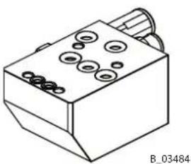
| 2308810 | Base plate GA 4000ACIC R (including seals and air connections) |
| 2363386 | Base plate, GA 4000ACIC S (including seals and air connections) |
natural_image
Technical line drawing of a mechanical component with circular holes and a protruding shaft (no text or symbols)
natural_image
Technical line drawing of a mechanical component with circular holes and a rectangular body (no text or symbols)5.3.4.2 AIR CAPS
| Order No. Designation | |
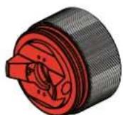
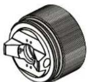
| 2308809 Air cap HV plus (blue) for high viscosity products | |
| 2308808 Air cap LV plus (red) for low viscosity products | |
| 2313493 Air cap LA plus (bronze) | |
| 2340299 Air cap LV plus (blank) |

B_03048
B_03049

B 03098
B_04231
5.3.4.3 ACF3000 AIRCOAT FLAT JET NOZZLES
| Order No. Designation | |
| 379XXX A selection guide for nozzles can be found in Chapter 13 _ |

B_00021
5.3.4.4 AIRCOAT ROUND JET NOZZLES ACR3000
| Order No. Designation | |
| 132XXX A selection guide for nozzles can be found in Chapter 13 _ |

natural_image
3D rendered mechanical component with threaded cylindrical body and central hub (no text or symbols)5.3.4.5 PRODUCT CONNECTIONS
| Order No. Designation | |
| 350550 Straight connecting fitting | |
| 2314065 Connecting fitting 90°; 1/4–NPSM | |
| 2328186 90° | connecting fitting; G1/4" |
5.3.4.6 AIR SUPPLY CONNECTIONS
| Order No. Designation | |
| 9998090 Straight threaded fitting 6 mm-1/8"; 0.24 inch-1/8" * standard | |
| 9998993 Straight threaded fitting 8 mm-1/8"; 5/16"21/8" |
5.3.4.7 SHUTTER PIN
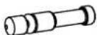
| Order No. Designation | |
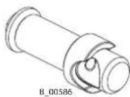
| 2310534 Complete lock pin |
5.3.4.8 PACKING INSERT GA 4000AC
| Order No. Designation | |
| 2313516 Packing Insert GA 4000AC | |
| 2338601 Packing insert GA 4000AC (RP) |
5.3.4.9 VALVE MOUNTING
| Order No. Designation | |
| 2314279 Valve mounting GA 4000AC complete (80° angle) | |
| 2340315 Valve mounting GA 4000AC complete (50° angle) |

B_03074

B_03097

B_06645

B_00507

B_00508
B_03050

B_04228

B_04232
5.4 DATA
5.4.1 MATERIALS OF PAINT-WETTED PARTS
| Metals Plastics | |||
| Carbide Stainless steel 1.430 | 5 POM FPM | ||
| Stainless steel 1.4310 Stainless steel 1.4104 PTFE PA 6.6 | |||
| UHMW-PE EPDM | |||
5.4.2 TECHNICAL DATA
| Description Units Value | ||
| Maximum air inlet pressure MPa; psi; bar 0.6; 87; 6 | ||
| Maximum product pressure MPa; psi; bar | 25; 3625; 250 | |
| Product connection (internal thread) | inch | G1/4" |
| Air connection (internal thread) | inch | G1/8" |
| Weight | G; oz | 880; 31 |
| Maximum product temperature | °C; °F | 80; 176 |
| Maximum air temperature | °C; °F | 50; 122 |
| Maximum ambient temperature | °C; °F | 5–40; 41–104 |
| Sound level at 0.3 MPa; 3 bar; 43.5 psi air pressure and 11 MPa; 110 bar; 1549 psi product pressure*** | dB(A) | 82.0 |
*** A rated sound pressure level measured at 0.5 m distance, Lpa 0.5 m, according to DIN EN 14462: 2005.
5.4.3 MEASUREMENTS AND CONNECTIONS

| Pos mm inch | |
| A 129 5.08 | |
| B 47 1.85 | |
| C 77.5 3.05 | |
| D 55 2.17 | |
| E 18±0.1 0.71±0.004 | |
| F 18±0.1 0.71±0.004 |


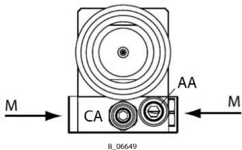
Connection data:
Base plate to GA 4000ACIC R
CA = G1/8" -> 6 mm; 0.24 inch control air
AA = G1/8" -> 8 mm; 0.31 inch atomizing air
M = G1/4" -> 1/4-NPSM product


| Pos mm inch | |
| A 129 5.08 | |
| B 52 2.04 | |
| C 61 2.40 | |
| D 37.5 1.48 | |
| E 18±0.1 0.71±0.004 | |
| F 18±0.1 0.71±0.004 |
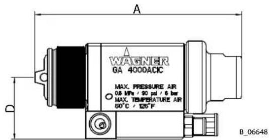

Connection data:
Base plate to GA 4000ACIC S
CA = G1/8" -> 6 mm; 0.24 inch control air
AA = G1/8" -> 8 mm; 0.31 inch atomizing air
M = G1/4" -> 1/4-NPSM product
M = G1/4" -> G1/4" product
6 COMMISSIONING
6.1 TRAINING OF ASSEMBLY/COMMISSIONING PERSONNEL
→ The assembly and commissioning personnel must have the technical skills to safely commission the device.
→ When assembling, commissioning and carrying out all work, read and follow the operating manuals and safety regulations for the additionally required system components.
A skilled person must check to ensure that the device is in a reliable state after it is installed and commissioned.
6.2 STORAGE CONDITIONS
Until the point of assembly, the device must be stored in a dry location, free from vibrations and with a minimum of dust. The device must be stored in closed rooms.
The air temperature at the storage location must be between -20 °C and +60 °C (-4 °F and +140 °F).
The relative air humidity at the storage location must be between 10 and 95% (without condensation).
6.3 INSTALLATION CONDITIONS
The air temperature at the installation site must be in a range between 0 °C and 40 °C (32 °F and 132 °F).
The relative air humidity at the installation site must be between 10 and 95% (without condensation).
6.4 INSTALLATION AND CONNECTION
The spray gun must be combined with various components to make up a spraying system. The spraying system shown in the figure is only one example of an AirCoat spraying system. Your WAGNER distributor would be happy to assist you in creating a spraying system solution that meets your individual needs.
You must familiarize yourself with the operating manuals and the safety regulations of all additional system components before starting commissioning.
6.4.1 TYPICAL AIRCOAT SPRAYING SYSTEM

| Pos | Designation Designation |
| A Control cabinet F Paint supply | |
| B Conveyor G Part recognition | |
| C Work piece H Spray guns | |
| D Spray booth I Supply air system and exhaust system | |
| E Reciprocator |
6.4.2 VENTILATION OF THE SPRAY BOOTH
→ Operate the device in a spray booth approved for the working materials.
-or-
→ Operate the device on an appropriate spraying wall with the ventilation (extraction) switched on.
→ Observe national and local regulations for the exhaust air speed.
6.4.3 AIR SUPPLY LINES
Ensure that only dry, clean atomizing air is used in the spray gun! Dirt and moisture in the atomizing air worsens the spraying quality and spray pattern.
6.4.4 PRODUCT SUPPLY LINES
NOTICE
Impurities in the spraying system!
Spray gun blockage, products harden in the spraying system.
→ Flush the spray gun and paint supply with a suitable flushing agent.
6.5 GROUNDING
A conductive connection (potential equalization cable) must be established between original tank and the equipment.
→ Ground all device components.
→ Ground the work pieces to be coated.
6.6 SAFETY CHECKS
→ Carry out safety checks in accordance with Chapter 8.2.3.
6.7 LACQUER PREPARATIONS
The viscosity of the lacquer is of great importance. The best spraying results are obtained with values between 80 and 260 millipascal x Sec (mPas).
Processing of up to 260 mPas is generally possible without problems if high coating thicknesses are required. It is important for the optimum coating quality that the paint temperature is kept constant during coating.
Please also read the technical data sheet of the lacquer for optimal processing, viscosity adjustment and intermixing of the product.
In the case of application problems contact the lacquer manufacturer.
6.7.1 VISCOSITY CONVERSION TABLE
| Millipascal x Sec (mPas) | Centipoise | Poise | DIN Cup 4 mm 0.16 inch | Ford Cup 4 | Zahn 2 |
| 10 10 0.1 | 5 16 | ||||
| 15 15 0.1 | 5 8 17 | ||||
| 20 20 0.2 | 10 18 | ||||
| 25 25 0.2 | 5 14 12 19 | ||||
| 30 30 0.3 | 15 14 20 | ||||
| 40 40 0.4 | 17 18 22 | ||||
| 50 50 0.5 | 19 22 24 | ||||
| 60 60 0.6 | 21 26 27 | ||||
| 70 70 0.7 | 23 28 30 | ||||
| 80 80 0.8 | 25 31 34 | ||||
| 90 90 0.9 | 28 32 37 | ||||
| 100 100 1 | 30 34 41 | ||||
| 120 120 1 | 2 33 41 49 | ||||
| 140 140 1 | 4 37 45 58 | ||||
| 160 160 1 | 6 43 50 66 | ||||
| 180 180 1 | 8 46 54 74 | ||||
| 200 200 2 | 49 58 82 | ||||
| 220 220 2 | 2 52 62 | ||||
| 240 240 2 | 4 56 65 | ||||
| 260 260 2 | 6 62 68 | ||||
| 280 280 2 | 8 65 70 | ||||
| 300 300 3 | 70 74 | ||||
| 320 320 3 | 2 | ||||
| 340 340 3 | 4 | ||||
| 360 360 3 | 6 80 | ||||
| 380 380 3 | 8 | ||||
| 400 400 4 | 90 |
6.8 COMMISSIONING
6.8.1 PREPARATION BEFORE COMMISSIONING
! NOTICE
Impurities in the spraying system!
Spray gun blockage.
→ Flush the spray gun and paint supply with a suitable flushing agent before commissioning.
6.8.2 COMMISSIONING
- Mount spray gun to reciprocator.
- Connect product hoses (supply and return flow) to spray gun and product supply system.
- Fit nozzle on nozzle seal. Fit air cap over nozzle.
Note the flattened parts (X) on the nozzle and in the air cap.
Fit the union nut and tighten by hand. - Connect control air hose and atomizing air hose to spray gun and to oil-free, dry air supply.
- Visually check the permissible pressures for all the system components.
- Make sure that the device and all other conductive parts within the work area are grounded.
- Set operating pressure to 100 MPa; 10 bar; 1,450 psi and use a suitable medium to check no connections are leaking.
- Relieve the pressure from the spray gun and device.

6.8.3 VERIFYING A SAFE OPERATIONAL CONDITION
A skilled person must check to ensure that the device is in a reliable state after it is installed and commissioned.
This includes:
- Carry out safety checks in accordance with Chapter 8.2.3.

7 OPERATION
→ The operating personnel must be qualified to operate the entire system.
→ The operating personnel must be familiar with the potential risks associated with improper behavior as well as the necessary protective devices and measures.
→ Before work commences, the operating personnel must receive appropriate system training.
7.2 TASKS

CAUTION
Spurting out of liquids with high pressure!
Risk of injury and damage to the device.
→ No persons should be located in the hazard area during operation.
→ Make sure to keep a safe distance during setting up, installation and maintenance work.

Ensure that:
→ The regular safety checks are carried out in accordance with Chapter 8.2.3,
→ commissioning is carried out in accordance with Chapter 6.8.
7.2.1 STARTING TO SPRAY WITH THE AIRCOAT
- Set product supply to operating pressure of approx. 8 MPa; 80 bar; 1160 psi and start up.
- Spray (release control air) and check the atomization.
- Set the spray pressure on the product supply such that optimum product atomization is attained.
- Open air pressure regulator for atomizing air and set.
- Adjust the amount of air at the shaping air throttle until the optimum spray pattern is reached.
The relation between the spray pattern and shaping is shown in the illustration below.
Note:
Repeat points 4 and 5 until the optimum spray pattern is reached (iterative process).
Spray pattern shapes
No shaping air/atomizing air
Too little shaping air/atomizing air
Correct amount of shaping air/atomizing air
B_00071
Note:
The flow rate can be changed by:
- changing the product pressure or
- Using a different flat jet nozzle (see Chapter 7.2.4 and Chapter 13).
7.2.2 ADJUSTING THE SPRAY PATTERN
The spray pattern can be adjusted to suit the object being sprayed using the shaping air regulator. The illustration shows the influence of the shaping air regulator on the spray pattern. Other nozzle sizes can be mainly used to obtain larger or smaller spray patterns.

7.2.3 PRESSURE RELIEF/WORK INTERRUPTION
The pressure must always be relieved:
– when the spraying tasks are finished,
– before carrying out maintenance work on the spraying system,
– before carrying out cleaning tasks on the spraying system,
– before moving the spraying system to another location,
- if something must be checked on the spraying system,
- if the nozzle or the filter is removed from the spray gun.
The components for pressure relief on a CE-compliant spray system include:
– Air cock with pressure relief hole mounted between compressed air source and pneumatic pump.
– Product pressure relief valve mounted between pump and spray gun.
Pressure Relief Procedure:
- Turn compressed air regulator for shaping and atomizing air on the superordinate control to "0".
- Close the compressed air supply on the material side upon the product pressure generator.
- Open product pressure relief valve (see system description) and relieve pressure from the system.
- Leave product pressure relief valve open.
If the pressure is still not completely relieved after this:
- If the nozzle is obstructed: loosen the union nut, remove the air cap and nozzle to release remaining pressure.
- If product hose is obstructed: slowly loosen the hose connections to release the remaining pressure.
Note:
Always follow the procedure described above if pressure relief is specified in the instructions.
7.2.4 CHANGING AIRCOAT NOZZLE

NOTICE
Defective AirCoat nozzle!
Insufficient paint application quality.
→ Do not use sharp-edged objects to treat carbide on the AirCoat nozzle.
- Relieve the pressure of gun and device.
- Secure gun (remove the control air hose).
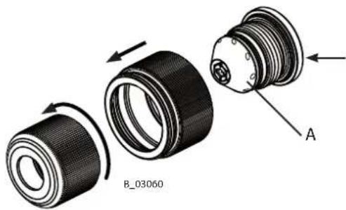
- Unscrew union nut (A).
- Remove air cap (B).
- Press AirCoat nozzle (C) out of air cap (B) by hand and treat with cleaning agent until all remaining paint has been dissolved.
- Fit AirCoat nozzle (C) in nozzle seal (D).
- Fit air cap (B) over nozzle (C). Note the flattened parts (X) on the nozzle and in the air cap.
- Fit the union nut with nozzle guard (A) and tighten by hand.
Assembly:

7.2.5 CLEANING AIRCOAT NOZZLE
For disassembly and assembly of AirCoat nozzles, see Chapter 7.2.4.
The AirCoat nozzle (C) can be placed into a cleaning solution which has been recommended by the paint manufacturer.
7.2.6 ELIMINATING NOZZLE CLOGGING
- Relieve the pressure of gun and device.
-
Secure gun (remove the control air hose).
-
Unscrew union nut (A).
-
Remove air cap (B).
-
Push AirCoat nozzle (C) out of air cap (B) by hand and place on nozzle seal (D) the other way round with the nozzle tip towards the rear.
-
Fit air cap (B) on nozzle (C).
Note the flattened parts (X) on the nozzle and in the air cap.
-
Screw on the union nut (A) over the air cap (B) onto the spray gun and tighten by hand.
-
Switch the product pressure back on.
-
Spray (connect control air hose).
-
When the blockage has been flushed out, switch off the spray gun.
-
Relieve the pressure of gun and device.
-
Secure gun (remove the control air hose).
-
Unscrew union nut (A).
-
Remove air cap (B) and push AirCoat nozzle (C) out by hand.
Clean nozzle and nozzle seal and refit nozzle in spraying position on nozzle seal (D).
- Fit air cap (B) on nozzle (C).
Note the flattened parts (X) on the nozzle and in the air cap.
-
Screw on the union nut (A) over the air cap (B) onto the spray gun and tighten by hand.
-
Connect control air.
Switch the product pressure and the air pressure back on.


Nozzle in cleaning position
7.2.7 REPLACING NOZZLE INSERT OF ROUND JET NOZZLE
- Relieve the pressure of gun and device.
- Secure gun (remove the control air hose).
- Remove nozzle insert (B) with nozzle spanner (A).
- Fit new nozzle insert in reverse order (see Chapter 8.2.6).
Note:
Flush out clogged round jet nozzle:
- Use nozzle spanner (A) to loosen nozzle insert (B) by a half turn.
- Remove the nozzle spanner and switch on the spray gun briefly.
- After flushing the nozzle, re-tighten the nozzle insert.

8 CLEANING AND MAINTENANCE
8.1 CLEANING
8.1.1 CLEANING PERSONNEL
Cleaning work should be undertaken regularly and carefully by qualified and trained personnel. They should be informed of specific hazards during their training.
The following hazards may arise during cleaning work:
– risk to health from inhaling solvent vapors,
– use of unsuitable cleaning tools and aids.
8.1.2 FLUSHING AND CLEANING THE GUN

NOTICE
Flushing agent in the air duct!
Functional faults caused by swollen seals.
→ When cleaning, always operate the spray gun at at least 0.05 MPa; 0.5 bar; 7.25 psi shaping air.
→ Always point the spray gun down when cleaning.
→ Ensure that neither paint nor flushing agent enters the air duct.
→ Never immerse the spray gun in cleaning agent.
The spray gun and the device must be cleaned and flushed daily. The cleaning/flushing agents used for cleaning or flushing must correspond with the working material.
- Relieve the pressure of gun and device.
- Secure gun (remove the control air hose).
- Connect the cleaning agent supply.
- Dismount AirCoat nozzle and clean separately (see Chapter 7.2.4).
- Pressurize the cleaning agent supply to a maximum pressure of 4 MPa; 40 bar; 580 psi and thoroughly flush the spray gun.
- Relieve the pressure of gun and device.
- Secure gun (remove the control air hose).
- Clean outside of spray gun with a cleaning agent recommended by the lacquer manufacturer and dry with a cloth or blow gun.
8.2 MAINTENANCE
8.2.1 MAINTENANCE PERSONNEL
Maintenance work should be undertaken regularly and carefully by qualified and trained personnel. They should be informed of specific hazards during their training.
The following hazards may arise during maintenance work:
– risk to health from inhaling solvent vapors,
- use of unsuitable tools and aids.
An authorized person must ensure that the device is checked for being in a reliable state after maintenance work is completed.
8.2.2 MAINTENANCE INSTRUCTIONS

DANGER
Incorrect maintenance/repair!
Danger to life and equipment damage.
→ Only a WAGNER service center or a suitably trained person may carry out repairs and replace parts.
→ Only repair and replace parts that are listed in the "Spare parts" chapter and that are assigned to the unit.
→ Before all work on the device and in the event of work interruptions:
– Switch off the energy and compressed air supply.
- Relieve the pressure from the spray gun and device.
- Secure the spray gun against actuation.
→ Observe the operating and service manual for all work.

Prior to Maintenance
- Flush and clean the system. Chapter 8.1.2
After maintenance
- Carry out safety checks in accordance with Chapter 8.2.3.
- Put the system into operation and check for leaks as described in Chapter 6.8.
→ In accordance with the guideline for liquid ejection devices (DGUV regulation 100-500 sections 2.29 and 2.36):
- The liquid ejection devices should be checked by an expert (e.g., WAGNER service technician) for their safe working conditions as required and at minimum every 12 months.
- For shut down devices, the examination can be suspended until the next start-up.
8.2.3 SAFETY CHECKS
8.2.3.1 GROUNDING CHECK
Daily: Before starting work, carry out a visual inspection to ensure that the system is grounded.
8.2.3.2 PRODUCT HOSES, PIPES AND COUPLINGS
The service life of the complete hoses between product pressure generator and application device is reduced due to environmental influences even when handled correctly.
→ Check hoses, pipes, and couplings every day and replace if necessary.
→ Additionally, the operator must regularly check the complete hoses for wear and tear as well as for damage at intervals that he/she has set. Records of these checks must be kept.
→ The complete hose is to be replaced as soon as one of the two following intervals has been exceeded:
- 6 years from the date of the hose crimping (see fitting embossing).
- 10 years from the date of the hose imprinting.
| Fitting embossing Meaning | |
| xxx bar Pressure | |
| yymm Crimping date (year/month) | |
| XX Internal code | |
| Hose imprinting Meaning | |
| Wagner Name/Manufacturer | |
| yymm Date of manufacture (year/month) | |
| xxx bar (xx MPa)e.g., 270 bar (27 MPa) | Pressure |
| XX Internal code | |
| DNxx (e.g., DN10) Nominal diameter | |
8.2.4 REPLACING THE PAINT HOSE
- Decommissioning work and cleaning.
- Relieve the pressure of gun and device.
- Secure gun (remove the control air hose).
- Place open-ended wrench size 17 mm; 0.67 inch on flats of product connection and counterhold.
- Unscrew nut of product hose with open-ended wrench size 19 mm; 0.75 inch.
6. Assembly:
Fit product hose by hand and tighten with 2 open-ended wrenches.

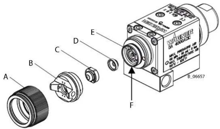
8.2.5 REPLACING THE NOZZLE SEAL
NOTICE
Shaping air and atomizer air not separate!
Poor spray pattern.
Spray jet cannot be adjusted.
→ Treat the distributor seal (F) with care.
- Decommissioning work and cleaning.
- Relieve the pressure of gun and device.
- Secure gun (remove the control air hose).
- Unscrew union nut (A).
- Remove air cap (B) and nozzle (C).
- Release the nozzle seal (D) with the help of a screwdriver.
- Fit new nozzle seal to valve housing (E).
- Assemble in reverse order.
8.2.6 REPLACING THE SEALING FITTING OF THE ROUND JET NOZZLE
NOTICE
Defective nozzle body!
Poor spray pattern.
→ Handle the nozzle body (A) with care.
Unscrew the nozzle by hand.
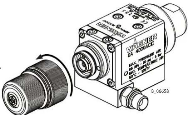
Hold in position with a size 13 mm; 0.51 inch socket wrench.
Nozzle wrench (D)
Order no. 128901

Eject with ∅ 1.5 mm; 0.06 inch pin.
Note:
The sealing fitting (E) can be pulled out of the nozzle body using a small eye wood bolt.

9 TROUBLESHOOTING AND RECTIFICATION
| Functional fault Cause Remedy See Chapter | |||
| Insufficient product output | Nozzle too small Select large | ger nozzle. 13 | — |
| Product pressure too low. | Increase product pressure. | ||
| Filter upstream of gun or high-pressure filter clogged at pump. | Clean or replace filter. | ||
| Nozzle clogged. Clean the | nozzle. 7.2.6 | — | |
| The valve rod path is too short. | Increase the control air pressure. | ||
| Replace the valve rod. | |||
| Poor spray pattern Atomizing air incorrectly adjusted. | Readjust the atomizing air. 7.2.1 | — | |
| Nozzle is too large. Select a smaller nozzle. | |||
| Nozzle worn. Replace the nozzle. 7.2.4 | — | ||
| Product pressure too low. | Increase the product pressure at pump. | ||
| The product viscosity is too high. | Dilute the spray product in accordance with the manufacturer's instructions. | ||
| Nozzle partially clogged. | Clean the nozzle. 7.2.5and7.2.6 | ||
| The drilled holes in the air cap are damaged or clogged. | Clean or replace the air cap. | ||
| Incorrectly selected air cap. | Use suitable air cap (high viscosity/low viscosity). | ||
| Air valve leaking / air leaks | The seals on the valve rod are damaged or the valve rod itself is damaged. | Replace the entire valve rod or the individual seals. | |
| Air valve seals are leaky. | Replace the air valve seal. 8.2.5 | — | |
| Packing leaking. | Packing worn. | Replace packing. | |
| Spray gun will not shut off correctly/product valve leaking. | The valve seat or the valve ball is damaged. | Replace the parts. | |
10 REPAIR WORK
10.1 REPAIR PERSONNEL
Repair work should be undertaken carefully by qualified and trained personnel. They should be informed of specific hazards during their training.
The following hazards may arise during repair work:
- risk to health from inhaling solvent vapors,
– use of unsuitable tools and aids.
A skilled person must check to ensure that the device is in a reliable state after it is repaired.
10.2 REPAIR NOTES

DANGER
Incorrect maintenance/repair!
Danger to life and equipment damage.
→ Only a WAGNER service center or a suitably trained person may carry out repairs and replace parts.
→ Only repair and replace parts that are listed in the "Spare parts" chapter and that are assigned to the unit.
→ Before all work on the device and in the event of work interruptions:
- Switch off the energy and compressed air supply.
- Relieve the pressure from the spray gun and device.
- Secure the spray gun against actuation.
→ Observe the operating and service manual for all work.

Before Repair Work
- Flush and clean the system according to Chapter 8.1.2.
After Repair Work
- Carry out safety checks in accordance with Chapter 8.2.3.
- Put the system into operation and check for leaks as described in Chapter 6.8.
- Function test in accordance with Chapter 11.
→ In accordance with the guideline for liquid ejection devices (DGUV regulation 100-500 sections 2.29 and 2.36):
- The liquid ejection devices should be checked by an expert (e.g., WAGNER service technician) for their safe working conditions as required and at minimum every 12 months.
- For shut down devices, the examination can be suspended until the next start-up.
10.3 REPLACING PARTS OF THE GUN BODY
10.3.1 DISASSEMBLY OF GA 4000ACIC
! NOTICE
Defective plunger shaft!
Packing leaking.
Greater wear on the packing.
→ Handle the plunger shaft (K) with care.
→ The plunger shaft has the function of a sliding surface.
Note:
The complete base plate (B) does not have to be removed.
M5 wrench size 3 mm; 0.12 inch


Note:
Circulation mode without lock pin

M5 wrench size 3 mm; 0.12 inch

Blow gun

Note:
Stuck components can be pushed out with a drift ∅ 3 mm; 0.12 inch.
Note:
Pull out distributor seal (F) using pliers.
M5 wrench size 12 mm; 0.47 inch


10.3.2 PACKING INSERT GA 4000AC (RP)

Order of seals:
1) Sealing set GA 4000 packing RP: Order No. 2339140
| Pos | Product Order No. Order No. (set of 12 packings) | |
| 1 PTFE + GF - 2339141 | ||
| 2 PE - 2339142 | ||
| 3 PTFE + GF - 2339141 | ||
| 4 PE - 2339142 | ||
| 5 PTFE + GF - 2339141 | ||
| 6 PTFE + GF - 2339141 | ||
| 7 Mobilux® EP 2 grease 380924 -- | ||
| 8 Vaseline white 9992698 -- | ||
2) Sealing set GA 4000 packing RP special: Order No. 2339810
| Pos | Product Order No. Order No. (set of 12 packings) | |
| 1 PTFE - 2339143 | ||
| 2 PE - 2339142 | ||
| 3 PTFE - 2339143 | ||
| 4 PE - 2339142 | ||
| 5 PTFE + GF - 2339141 | ||
| 6 PTFE + GF - 2339141 | ||
| 7 Mobilux® EP 2 grease 380924 -- | ||
| 8 Vaseline white 9992698 -- | ||
10.3.3 ASSEMBLY OF GA 4000ACIC
General note:
Lightly grease o-rings and sliding surfaces with Vaseline white PHV II.
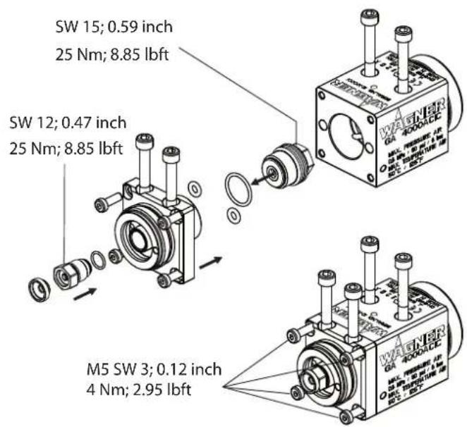

Note:
Put distributor seal (G) on air cap (H) and place seal and air cap in gun housing. Screw union nut (K) in until the distributor seal ring catches in the groove (audible click).
Dismount union nut and air cap again.

M5 wrench size 3 mm; 0.12 inch 4 Nm; 2.95 lbft

11 FUNCTION TEST AFTER REPAIR WORK
After all repair work, the spray gun must be checked for safe condition before recommissioning. The necessary scope of inspection and testing depends on the repair carried out and must be documented by the repair personnel.
12 DISPOSAL
When the equipment must be scrapped, please differentiate the disposal of the waste materials.
The following materials have been used:
- Stainless steel
- Aluminum
- Elastomers
- Plastic
- Carbide
The consumable products (lacquers, adhesives, solvents) must be disposed of in accordance with the applicable specific standards.
13 ACCESSORIES
13.1 AIRCOAT NOZZLES ACF3000
| Order No. | Marking | Drilled hole∅inch; mm | Spray angle | Recommended gun filter | ||
| Recommended edge filter | ||||||
| Application | ||||||
| 379107 07/ | 10 0.007-0.18 | 10° Natural lacquer | Red 200 mesh | 200 mesh | ||
| 379207 07/ | 20 0.007-0.18 | 20° | ||||
| 379209 09/ | 20 0.009-0.23 | 20° Clear lacquer | ||||
| 379309 09/ | 30 0.009-0.23 | 30° Oils | ||||
| 379409 09/ | 40 0.009-0.23 | 40° | ||||
| 379509 09/ | 50 0.009-0.23 | 50° | ||||
| 379609 09/ | 60 0.009-0.23 | 60° | ||||
| 379111 11/ | 10 0.011-0.28 | 10° Synthetic resin lacquer | ||||
| 379211 11/ | 20 0.011-0.28 | 20° PVC lacquer | ||||
| 379311 11/ | 30 0.011-0.28 | 30° | ||||
| 379411 11/ | 40 0.011-0.28 | 40° | ||||
| 379511 11/ | 50 0.011-0.28 | 50° | ||||
| 379611 11/ | 60 0.011-0.28 | 60° | ||||
| 379113 13/ | 10 0.013-0.33 | 10° Lacquers | ||||
| 379213 13/ | 20 0.013-0.33 | 20° Base coat | ||||
| 379313 13/ | 30 0.013-0.33 | 30° Primer | ||||
| 379413 13/ | 40 0.013-0.33 | 40° Filler | ||||
| 379513 13/ | 50 0.013-0.33 | 50° | ||||
| 379613 13/ | 60 0.013-0.33 | 60° | ||||
| 379813 13/ | 80 0.013-0.33 | 80° | ||||
| 379115 15/ | 10 0.015-0.38 | 10° Filler | ||||
| 379215 15/ | 20 0.015-0.38 | 20° Rust proofing paints | ||||
| 379315 15/ | 30 0.015-0.38 | 30° | ||||
| 379415 15/ | 40 0.015-0.38 | 40° | ||||
| 379515 15/ | 50 0.015-0.38 | 50° | ||||
| 379615 15/ | 60 0.015-0.38 | 60° | ||||
| 379815 15/ | 80 0.015-0.38 | 80° | ||||
| 379217 17/ | 20 0.017-0.43 | 20° Rust proofing paints | ||||
| 379317 17/ | 30 0.017-0.43 | 30° Latex paints | ||||
| 379417 17/ | 40 0.017-0.43 | 40° | ||||
| 379517 17/ | 50 0.017-0.43 | 50° | ||||
| 379617 17/ | 60 0.017-0.43 | 60° | ||||
| 379817 17/ | 80 0.017-0.43 | 80° | ||||

| Order No. | Marking | Drilled hole∅inch; mm | Spray angle | Recommended gun filter | |
| Recommended edge filter | |||||
| Application | |||||
| 379219 19/ | 20 0.019-0.48 | 20° Rust proofing paints | White 50 mesh | 60 mesh | |
| 379319 19/ | 30 0.019-0.48 | 30° Latex paints | |||
| 379419 19/ | 40 0.019-0.48 | 40° | |||
| 379519 19/ | 50 0.019-0.48 | 50° | |||
| 379619 19/ | 60 0.019-0.48 | 60° | |||
| 379819 19/ | 80 0.019-0.48 | 80° | |||
| 379221 21/ | 20 0.021-0.53 | 20° Mica paints | |||
| 379421 21/ | 40 0.021-0.53 | 40° Zinc rich paints | |||
| 379521 21/ | 50 0.021-0.53 | 50° Rust proofing paints | |||
| 379621 21/ | 60 0.021-0.53 | 60° Glue paints | |||
| 379821 21/ | 80 0.021-0.53 | 80° | |||
| 379423 23/ | 40 0.023-0.58 | 40° | |||
| 379623 23/ | 60 0.023-0.58 | 60° | |||
| 379823 23/ | 80 0.023-0.58 | 80° | |||
| 379425 25/ | 40 0.025-0.64 | 40° | |||
| 379625 25/ | 60 0.025-0.64 | 60° | |||
| 379825 25/ | 80 0.025-0.64 | 80° | |||
| 379427 27/ | 40 0.027-0.69 | 40° | |||
| 379627 27/ | 60 0.027-0.69 | 60° | |||
| 379827 27/ | 80 0.027-0.69 | 80° | |||
| 379429 29/ | 40 0.029-0.75 | 40° | |||
| 379629 29/ | 60 0.029-0.75 | 60° | |||
| 379829 29/ | 80 0.029-0.75 | 80° | |||
| 379431 31/ | 40 0.031-0.79 | 40° | |||
| 379531 31/ | 60 0.031-0.79 | 60° | |||
| 379631 31/ | 80 0.031-0.79 | 80° | |||
| 379435 35/ | 40 0.035-0.90 | 40° | |||
| 379635 35/ | 60 0.035-0.90 | 60° | |||
| 379835 35/ | 80 0.035-0.90 | 80° | |||

B_00021
13.2 AIRCOAT NOZZLES ACF3000 S2 (4 PIECES)
| Order No. | Marking Drilled hole inch; mm Spray angle | ||
| 2391811 | 9/40 | S2 0.009; 0.23 40° | |
| 2391809 | 11/10 | S2 0.011; 0.28 10° | |
| 2368877 | 11/20 | S2 0.011; 0.28 20° | |
| 2396188 | 11/30 | S2 0.011; 0.28 30° | |
| 2368879 | 11/40 | S2 0.011; 0.28 40° | |
| 2368896 | 11/60 | S2 0.011; 0.28 60° | |
| 2368876 | 11/80 | S2 0.011; 0.28 80° | |
| 2368880 | 13/40 | S2 0.013; 0.33 40° | |
| 2368897 | 13/60 | S2 0.013; 0.33 60° | |
| 2368898 | 13/80 | S2 0.013; 0.33 80° | |
| 2368899 | 15/60 | S2 0.015; 0.38 60° | |
| 2396189 | 17/80 | S2 0.017; 0.43 80° | |

B_00021
13.3 ROUND JET NOZZLE ATTACHMENT
| Order No. | Designation |
| 394180 | Round jet nozzle attachment (without nozzle insert) |

13.3.1 RXX NOZZLE INSERTS
| Order No. | Designation Marking Jet ** | ∅ | |
| 132720 | Nozzle insert R11 11 approx. 250; 9.84 | ||
| 132721 | Nozzle insert R12 12 approx. 250; 9.84 | ||
| 132722 | Nozzle insert R13 13 approx. 250; 9.84 | ||
| 132723 | Nozzle insert R14 14 approx. 250; 9.84 | ||
| 132724 | Nozzle insert R15 15 approx. 250; 9.84 | ||
| 132725 | Nozzle insert R16 16 approx. 250; 9.84 | ||
| 132726 | Nozzle insert R17 17 approx. 250; 9.84 | ||
| 132727 | Nozzle insert R18 18 approx. 250; 9.84 | ||
| 132728 | Nozzle insert R19 19 approx. 250; 9.84 | ||
| 132729 | Nozzle insert R20 20 approx. 250; 9.84 | ||
| 132730 | Nozzle insert R21 21 approx. 250; 9.84 | ||
| 132731 | Nozzle insert R22 22 approx. 250; 9.84 |

** Jet width in mm; inches at a distance of approx. 30 cm; 11.8 inches from the object and at a pressure of 10 MPa; 100 bar; 1450 psi, synthetic resin paint, 20 DIN4 seconds.
13.3.2 NOZZLE SCREW JOINT, COMPLETE
| Order No. Designation | |
| 132922 Nozzle screw joint, complete |

13.4 HOSES
| Order No. | Designation |
| 9984405 | High-pressure hose M16x1.5, 1 m; 3.28 ft, DN 4 mm; ID 0.16 inch, 27 MPa; 270 bar; 3916 psi |
| 9984507 | High-pressure hose M16x1.5, 15 m; 98.4 ft, DN 6 mm; ID 0.24 inch, 27 MPa; 270 bar; 3916 psi |
| 9984510 | High-pressure hose M16x1.5, 7.5 m; 24.6 ft, DN 4 mm; ID 0.16 inch, 27 MPa; 270 bar; 3916 psi |
| 9984573 | High-pressure hose NPSM1/4", 7.5 m; 24.6 ft, DN 4 mm; ID 0.16 inch, 27 MPa; 270 bar; 3916 psi |
| 9984574 | High-pressure hose NPSM1/4"; 15 m; 98.4 ft, DN 6 mm; ID 0.24 inch, 27 MPa; 270 bar; 3916 psi |
| 9982035 | Air hose, red, outer 6mm; 0.24 inch, inner 4 mm; 0.16 inch, polyamide, per meter |
| 9982061 | Air hose, blue, outer 6mm; 0.24 inch, inner 4 mm; 0.16 inch, polyamide, per meter |
| 9982033 | Air hose, green, outer 6mm; 0.24 inch, inner 4 mm; 0.16 inch, polyamide, per meter |
| 9982062 | Air hose, blue, outer 8mm; 0.32 inch, inner 5.5mm; 0.22 inch, polyamide, per meter |
13.5 MISCELLANEOUS
| Order No. Designation | |
| 9997001 Nozzle cleaning brush | |
| 8612001 Nozzle cleaning needle set, 12 pieces | |
| 123446 Double fitting M16x1.5 (for extension for product hose) | |
| 367560 Double fitting NPSM 1/4" for product hose extension | |
| 380941 | Standard mounting bracket, 180 mm; ∅16 mm, 7.1 inches; ∅63 inch |
| 2314079 Cefla adapter plate | |
| 380942 Rotary gun holder (standard) | |
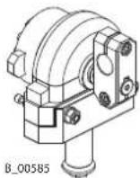
| 380945 Rotary holder, 40/40/5 | |
| 380943 Complete swivel drive | |
| 380944 Cross clamp for swivel drive | |



14 SPARE PARTS
14.1 HOW CAN SPARE PARTS BE ORDERED?
Always supply the following information to ensure delivery of the right spare part:
Order number, designation and quantity
The quantity need not be the same as the number given in the quantity column "Stk" the list. This number merely indicates how many of the respective parts are used in each component.
The following information is also required to ensure smooth processing of your order:
- address for the invoice,
- address for delivery,
– name of the person to be contacted in the event of any queries, - type of delivery (normal mail, express delivery, air freight, courier, etc.).
Identification in spare parts lists.
Explanation of column "K (labeling) in the following spare parts lists:
◆ Wearing part
Note: These parts are not covered by warranty terms.
● Not part of standard equipment, available, however, as additional extra.

DANGER
Incorrect maintenance/repair!
Danger to life and equipment damage.
→ Only a WAGNER service center or a suitably trained person may carry out repairs and replace parts.
→ Only repair and replace parts that are listed in the "Spare parts" chapter and that are assigned to the unit.
→ Before all work on the device and in the event of work interruptions:
→ Only a WAGNER service center or a suitably trained person may carry out repairs and replace parts.
→ Only repair and replace parts that are listed in the "Spare parts" chapter and that are assigned to the unit.
→ Before all work on the device and in the event of work interruptions:
– Switch off the energy and compressed air supply.
- Relieve the pressure from the spray gun and device.
- Secure the spray gun against actuation.
→ Observe the operating and service manual for all work.

14.2 SPARE PARTS LIST FOR GA 4000ACIC
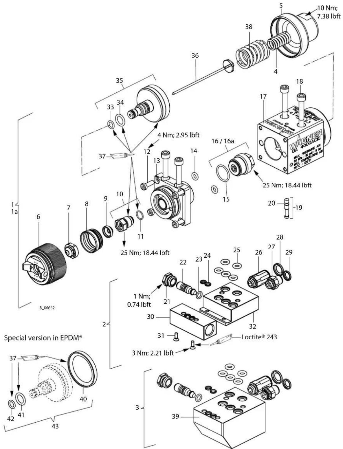
* EPDM version suitable for UV lacquers and acetone
| Pos K | Stk | Order No. | Designation |
| 1 1 2812132 | Spray gun body, GA | 4000ACIC | |
| 1a 1 338603 | Spray gun body, GA | 4000ACIC (RP) | |
| 2 1 280386 | Base plate, GA | 4000ACIC-S, complete | |
| 3 1 280810 | Base plate, GA | 4000ACIC-R, complete | |
| 4 1 2309945 | Helical spring | ||
| 5 1 2314274 | End cap short | ||
| 6 1 2308808 | Air cap LV plus (red) | ||
| 6 1 2308809 | Air cap HV plus (blue) | ||
| 6 1 2303493 | Air cap LA plus (bronze) | ||
| 6 1 2300299 | Air cap LV plus (blank) | ||
| 7 1 37... | AC nozzle | ||
| 8 1 394339 | Sealing ring | ||
| 9 1 364328 | Nozzle seal | ||
| 10 1 314279 | Valve housing, complete | ||
| 11 1 974245 | O-ring | ||
| 12 4 2307893 | Socket cap screw | ||
| 13 1 2314278 | Head piece | ||
| 14 2 974153 | O-ring | ||
| 15 1 67528 | O-ring | ||
| 16 1 313516 | Packing insert GA | 4000AC (standard version, can only be replaced completely) | |
| 16a 1 2338601 | Packing insert GA | 4000AC (RP) | |
| 17 1 2314277 | Piston housing IC | ||
| 18 4 2308292 | Socket cap screw | ||
| 19 1 2010534 | Complete product channel lock pin | ||
| 20 1 307873 | O-ring | ||
| 21 1 2307739 | Mounting nut | ||
| 22 1 2307868 | Round spray jet reduction | ||
| 23 1 971388 | O-ring | ||
| 24 2 310473 | Sealing product | ||
| 25 5 974265 | O-ring | ||
| 26 1 9998993 | Straight screw-in fitting | ||
| 27 1 9998090 | Straight screw-in fitting | ||
| 28 1 9998618 | Coding ring blue | ||
| 29 1 9998995 | Coding ring red | ||
| 30 1 2382911 | Product adapter plate | ||
| 31 2 2310556 | Hexagon socket countersunk head screw | ||
| 32 1 2316367 | Adapter plate IC-S | ||
| 33 1 48314 | O-ring | ||
| 34 1 971025 | O-ring | ||
| 35 1 314275 | IC piston, complete | ||
| 36 1 346098 | IC valve rod, complete | ||
| 37 1 9902698 | Vaseline white PHHV | ||
| 38 1 9998991 | Helical spring |
◆ = Wearing parts
-> For service sets, see Chapter 14.3.
● = Not part of the standard equipment but available as a special accessory
| Pos K | Stk | Order No. | Designation |
| 39 1 231424 | 2 Base | plate, GA 4000 | ACIC R |
| 40 1♦3♦253 | 1 Piston seal EPDM | ||
| 41 1♦3♦253 | 0 O-ring | ||
| 42 1♦9♦417 | 9 O-ring | ||
| 43 1♦3♦253 | 2 Seal set, GA 4000 | ACIC (EPDM) |
◆ = Wearing parts
-> For service sets, see Chapter 14.3.
● = Not part of the standard equipment but available as a special accessory
14.3 SERVICE SETS AND SPARE PARTS GROUPS
| Order No. | Designation Consisting of spare parts items | |
| 2314353 | Service set - Spray gun body, GA 4000ACIC 8, 9, 11 | 14, 16, 33, 34 |
| 2338657 | Service set - Spray gun body, GA 4000ACIC (RP) | 8, 9, 11, 14, 33, 34 |
| 2314355 | Service set - Base plate, GA 4000ACIC 23, 24, 25 | |
| 2322532 | Seal set, GA 4000ACIC (EPDM) 40, 41, 42 |
14.4 PACKING INSERT GA 4000AC (RP)
| Spare parts list set of 12 | packings | |||
| Pos K | Designation Order No. Order No. | Stk | ||
| 1 | Packing insert GA 4000AC (RP) | 1 | 2338601 | -- |
| 2 | Housing | 1 | -- | -- |
| 3 ◆ | PE sealing washer | 2 | -- | 2339142 |
| 4 | Housing insert | 1 | -- | -- |
| 5 | Housing screw | 1 | -- | -- |
| 6 ◆ | Pressure disk | 1 | 2338567 | -- |
| 7 ◆ | O-ring | 1 | 9974196 | -- |
| 8 ◆ | O-ring | 1 | 367528 | -- |
| 9 ◆ | O-ring | 1 | 2338570 | -- |
| 10 | Mobilux® EP 2 grease | 1 | 9998808 | -- |
| 11 | Vaseline white, PHHV II | 1 | 9992698 | -- |
| 12 ◆ | PTFE + GF sealing washer | 4 | -- | 2339141 |
| 13 ◆● | PTFE sealing washer | 2 | -- | 2339143 |
| 14 | Assembly manual for GA4000AC packing (RP) | 1 | 2338708 | -- |
◆ = Wearing parts
-> For sealing sets, see Chapter 14.5.
● = Not part of the standard equipment but available as a special accessory.
Packing insert

14.5 SEALING SET GA 4000 PACKING RP AND RP SPECIAL
| Order No. | Designation Consisting of spare parts items | |
| 2339140 | Sealing set GA 4000 packing RP 3, 6, 7, 8, 9, 12, 14 | |
| 2339810 | Sealing set GA 4000 packing RP special 3, 6, 7, 8, 9, 12, 13, 14 |
15 DECLARATION OF CONFORMITY
15.1 EU DECLARATION OF CONFORMITY
Herewith we declare that the supplied version of:
GA 4000ACIC
complies with the following guidelines:
| 2006/42/EC |
| 2014/34/EU |
Applied standards, in particular:
| EN ISO 12100: 2010 EN ISO 80079-36: 2016 | |
| EN 1953:2013 EN ISO/IEC 80079-34: 2011 | |
| EN ISO 13732-1: 2008 | |
| EN 14462:2015 | |
| EN 1127-1:2011 | |
Applied national technical standards and specifications, in particular:
| DGUV regulation 100-500 Chapter 2.29 | |
| DGUV regulation 100-500 Chapter 2.36 | |
| TRGS 727 |
Identification:


II 2G X
EU Declaration of Conformity
The EU Declaration of Conformity is enclosed with this product. If needed, further copies can be ordered through your WAGNER dealer by specifying the product name and serial number.
Order number: 2315627

natural_image
Simple line drawing of a pencil resting on a lined notepad (no text or symbols)WAGNER
Order No. 2312956
Edition 05/2018
Germany
J. Wagner GmbH
Phone +41/(0)71/7572211
Telefax +41/(0)71/7572222
More contact addresses:
www.wagner-group.com
Subject to changes without notice


- Translation of the Original Operating Manual
- Table of Contents
- ABOUT THESE INSTRUCTIONS 6
- CORRECT USE 9
- IDENTIFICATION
- BASIC SAFETY INSTRUCTIONS
- DESCRIPTION
- COMMISSIONING 31
- OPERATION 36
- CLEANING AND MAINTENANCE 41
- TROUBLESHOOTING AND RECTIFICATION 46
- REPAIR WORK 47
- FUNCTION TEST AFTER REPAIR WORK 54
- DISPOSAL 54
- ACCESSORIES 55
- SPARE PARTS 60
- DECLARATION OF CONFORMITY 65
- ABOUT THESE INSTRUCTIONS
- PREFACE
- WARNINGS, NOTICES AND SYMBOLS IN THESE INSTRUCTIONS
- DANGER
- WARNING
- CAUTION
- NOTICE
- Explanation of warning notice:
- LEVEL OF DANGER
- LANGUAGES
- ABBREVIATIONS
- CORRECT USE
- DEVICE TYPE
- TYPE OF USE
- FOR USE IN POTENTIALLY EXPLOSIVE AREAS
- PROCESSIBLE WORKING MATERIALS
- Note:
- MISUSE
- EXPLOSION PROTECTION IDENTIFICATION
- IDENTIFICATION "X"
- Safe Handling of WAGNER Spray Devices
- Ignition temperature of the coating product
- Medium supporting atomizing
- Cleaning
- TYPE PLATE
- SAFETY INSTRUCTIONS FOR THE OPERATOR
- ELECTRICAL DEVICES AND EQUIPMENT
- Electric shock hazard!
- A SAFE WORK ENVIRONMENT
- Hazard due to dangerous fluids or vapors!
- PERSONNEL QUALIFICATIONS
- Hazard due to incorrect use of device!
- SAFETY INSTRUCTIONS FOR THE PERSONNEL
- PERSONAL SAFETY EQUIPMENT
- SAFE HANDLING OF WAGNER SPRAY DEVICES
- Hazard due to injection of lacquer or flushing agent into the skin!
- In the event of skin injuries caused by lacquer or flushing agents:
- GROUNDING THE UNIT
- Hazard due to electrostatic charge!
- PRODUCT HOSES
- Hazard due to bursting of product hose!
- CLEANING AND FLUSHING
- Hazard due to cleaning and flushing!
- External Cleaning
- Hazard due to hot surfaces because of hot coating products!
- Order No.
- MAINTENANCE AND REPAIR
- Hazard due to improper maintenance and repair!
- PROTECTIVE AND MONITORING EQUIPMENT
- Hazard due to removal of protective and monitoring equipment!
- COMPONENTS
- FUNCTIONAL DESCRIPTION
- MODE OF OPERATION
- Diagram:
- Open:
- Close:
- Additional functions:
- MODE "NC" AND "C"
- Spurting out of liquids with high pressure!
- MODE "NC" WITHOUT PRODUCT CIRCULATION
- MODE "C" WITH PRODUCT CIRCULATION
- SPRAYING PROCEDURE
- AIRCOAT FLAT SPRAYING PROCEDURE
- Advantages:
- AIRCOAT ROUND SPRAYING PROCEDURE
- INCLUDED ITEMS
- TYPE DESCRIPTION
- GA 4000 AC XX
- OVERVIEW
- STANDARD VARIANT
- SUPPLEMENTARY COMPONENTS
- BASE PLATE
- AIR CAPS
- ACF3000 AIRCOAT FLAT JET NOZZLES
- AIRCOAT ROUND JET NOZZLES ACR3000
- PRODUCT CONNECTIONS
- AIR SUPPLY CONNECTIONS
- SHUTTER PIN
- PACKING INSERT GA 4000AC
- VALVE MOUNTING
- DATA
- MATERIALS OF PAINT-WETTED PARTS
- TECHNICAL DATA
- MEASUREMENTS AND CONNECTIONS
- Connection data:
- COMMISSIONING
- TRAINING OF ASSEMBLY/COMMISSIONING PERSONNEL
- STORAGE CONDITIONS
- INSTALLATION CONDITIONS
- INSTALLATION AND CONNECTION
- TYPICAL AIRCOAT SPRAYING SYSTEM
- VENTILATION OF THE SPRAY BOOTH
- AIR SUPPLY LINES
- PRODUCT SUPPLY LINES
- Impurities in the spraying system!
- GROUNDING
- SAFETY CHECKS
- LACQUER PREPARATIONS
- COMMISSIONING
- PREPARATION BEFORE COMMISSIONING
- ! NOTICE
- COMMISSIONING
- VERIFYING A SAFE OPERATIONAL CONDITION
- OPERATION
- TASKS
- STARTING TO SPRAY WITH THE AIRCOAT
- Spray pattern shapes
- ADJUSTING THE SPRAY PATTERN
- PRESSURE RELIEF/WORK INTERRUPTION
- Pressure Relief Procedure:
- CHANGING AIRCOAT NOZZLE
- Defective AirCoat nozzle!
- Assembly:
- CLEANING AIRCOAT NOZZLE
- ELIMINATING NOZZLE CLOGGING
- REPLACING NOZZLE INSERT OF ROUND JET NOZZLE
- CLEANING AND MAINTENANCE
- CLEANING
- CLEANING PERSONNEL
- FLUSHING AND CLEANING THE GUN
- Flushing agent in the air duct!
- MAINTENANCE
- MAINTENANCE PERSONNEL
- MAINTENANCE INSTRUCTIONS
- Incorrect maintenance/repair!
- Prior to Maintenance
- After maintenance
- SAFETY CHECKS
- GROUNDING CHECK
- PRODUCT HOSES, PIPES AND COUPLINGS
- REPLACING THE PAINT HOSE
- Assembly:
- REPLACING THE NOZZLE SEAL
- Shaping air and atomizer air not separate!
- REPLACING THE SEALING FITTING OF THE ROUND JET NOZZLE
- Defective nozzle body!
- REPAIR WORK
- REPAIR PERSONNEL
- REPAIR NOTES
- Before Repair Work
- After Repair Work
- REPLACING PARTS OF THE GUN BODY
- DISASSEMBLY OF GA 4000ACIC
- Defective plunger shaft!
- PACKING INSERT GA 4000AC (RP)
- Order of seals:
- ASSEMBLY OF GA 4000ACIC
- General note:
- FUNCTION TEST AFTER REPAIR WORK
- DISPOSAL
- ACCESSORIES
- RXX NOZZLE INSERTS
- NOZZLE SCREW JOINT, COMPLETE
- HOSES
- SPARE PARTS
- HOW CAN SPARE PARTS BE ORDERED?
- Order number, designation and quantity
- Identification in spare parts lists.
- SERVICE SETS AND SPARE PARTS GROUPS
- PACKING INSERT GA 4000AC (RP)
- DECLARATION OF CONFORMITY
- EU DECLARATION OF CONFORMITY
- GA 4000ACIC
- EU Declaration of Conformity
- WAGNER
- Germany
Brand : WAGNER
Model : GA 4000ACIC-S
Category : Pistolet de peinture automatique