VC550 - Video Conferencing System AVer - Free user manual and instructions
Find the device manual for free VC550 AVer in PDF.


| Product Type | PTZ Video Conferencing Camera |
| Model | AVer VC550 |
| Image Sensor | 1/2.8-inch CMOS |
| Video Resolution | 1080p Full HD (1920x1080) at 60 fps |
| Optical Zoom | 12x |
| Digital Zoom | Up to 12x (total 144x) |
| Horizontal Field of View | 72.5° |
| Pan Range | ±170° |
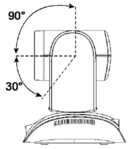
| Tilt Range | +90° / -30° |
| Video Output | HDMI, USB 3.0 (UVC), IP (RJ45) |
| Audio | Built-in microphone (2x) with echo cancellation |
| Power Supply | DC 12V or PoE+ (IEEE 802.3at) |
| Power Consumption | ≤ 15W |
| Dimensions (W x H x D) | 180 x 158 x 147 mm (7.08 x 6.22 x 5.79 in) |
| Weight | 1.6 kg (3.53 lbs) |
| Mounting | Tabletop or ceiling mount (optional bracket) |
| Main Functions | Auto framing, remote control, preset positions, USB plug-and-play |
| Compatibility | Zoom, Microsoft Teams, Skype, etc. (UVC standard) |
| Maintenance | Clean lens with lint-free cloth; keep vents clear |
| Safety | Secure mounting to prevent falling; use approved power supply |
| Spare Parts & Repairability | Contact AVer support for remote diagnostics; no user-serviceable parts |
| Warranty | 3 years limited warranty (check local terms) |
| Regulatory Approvals | FCC, CE, VCCI, RoHS |
Frequently Asked Questions - VC550 AVer
User questions about VC550 AVer
0 question about this device. Answer the ones you know or ask your own.
Ask a new question about this device
Download the instructions for your Video Conferencing System in PDF format for free! Find your manual VC550 - AVer and take your electronic device back in hand. On this page are published all the documents necessary for the use of your device. VC550 by AVer.
USER MANUAL VC550 AVer
natural_image
Technical line drawing of a mechanical component with two views: top shows cylindrical housing and circular ring, bottom shows flanged circular component (no text or symbols)VC550
User Manual
Federal Communications Commission Statement
NOTE: This equipment has been tested and found to comply with the limits for a Class A digital device, pursuant to part 15 of the FCC Rules. These limits are designed to provide reasonable protection against harmful interference when the equipment is operated in a commercial environment. This equipment generates, uses, and can radiate radiofrequency energy and, if not installed and used in accordance with the instruction manual, may cause harmful interference to radio communications. Operation of this equipment in a residential area is likely to cause harmful interference in which case the user will be required to correct the interference at his own expense.
FCC Caution: Any changes or modifications not expressly approved by the party responsible for compliance could void the user's authority to operate this equipment.
This device complies with part 15 of the FCC Rules.
Operation is subject to the following two conditions:
(1) This device may not cause harmful interference, and
(2) this device must accept any interference received, including interference that may cause undesired operation.
Warning:
This is a class A product. In a domestic environment this product may cause radio interference in which case the user may be required to take adequate measures.
No warranty or representation, either expressed or implied, is made with respect to the contents of this documentation, its quality, performance, merchantability, or fitness for a particular purpose. Information presented in this documentation has been carefully checked for reliability; however, no responsibility is assumed for inaccuracies. The information contained in this documentation is subject to change without notice.
In no event will AVer Information Inc. be liable for direct, indirect, special, incidental, or consequential damages arising out of the use or inability to use this product or documentation, even if advised of the possibility of such damages.
TRADEMARKS
“AVer” is a trademark owned by AVer Information Inc. Other trademarks used herein for description purpose only belong to each of their companies.
COPYRIGHT
© 2022 AVer Information Inc. All rights reserved. | April 29, 2022
All rights of this object belong to AVer Information Inc. Reproduced or transmitted in any form or by any means without the prior written permission of AVer Information Inc. is prohibited. All information or specifications are subject to change without prior notice.
NOTICE
SPECIFICATIONS ARE SUBJECT TO CHANGE WITHOUT PRIOR NOTICE. THE INFORMATION CONTAINED HEREIN IS TO BE CONSIDERED FOR REFERENCE ONLY.
WARNING
■ To reduce risk of fire or electric shock, do not expose this appliance to rain or moisture. Warranty will be void if any unauthorized modifications are done to the product.
■ Do not drop the camera or subject it to physical shock.
■ Use correct power supply voltage to avoid damaging camera.
■ Do not place the camera where the cord can be stepped on as this may result in fraying or damage to the lead or the plug.
■ Hold the bottom of the camera with both hands to move the camera. Do not grab the lens or lens holder to move the camera.
Remote Control Battery Safety Information
- Store batteries in a cool and dry place.
- Do not throw away used batteries in the trash. Properly dispose of used batteries through specially approved disposal methods.
- Remove the batteries if they are not in use for long periods of time. Battery leakage and corrosion can damage the remote control. Dispose of batteries safely and through approved disposal methods.
- Do not use old batteries with new batteries.
- Do not mix and use different types of batteries: alkaline, standard (carbon-zinc) or rechargeable (nickel-cadmium).
- Do not dispose of batteries in a fire.
- Do not attempt to short-circuit the battery terminals.
CAUTION
- Risk of explosion if battery is replaced by an incorrect type.
- Dispose of used batteries in a safe and proper manner.
遥控器电池安全信息
For FAQs, technical support, software and user manual download, please visit:
Headquarters
Download Center: https://www.aver.com/download-center
Technical Support: https://www.aver.com/technical-support
USA Branch office
Download Center: https://www.averusa.com/business/support/
Technical Support: https://averusa.force.com/support/s/contactsupport
Europe Branch office
Download Center: https://www.avereurope.com/download-center
Technical Support: https://www.avereurope.com/technical-support
Contact Information
Headquarters
AVer Information Inc.
https://www.aver.com
8F, No.157, Da-An Rd., Tucheng Dist., New Taipei City 23673, Taiwan
Tel: +886 (2) 2269 8535
USA Branch office
AVer Information Inc., Americas
https://www.averusa.com
668 Mission Ct., Fremont, CA 94539, USA
Tel: +1 (408) 263 3828
Toll-free: +1 (877) 528 7824
Technical support: support.usa@aver.com
Europe Branch office
AVer Information Europe B.V.
https://www.avereurope.com
Westblaak 134, 3012 KM, Rotterdam, The Netherlands
Tel: +31 (0) 10 7600 550
Technical support: eu.rma@aver.com
Japan Branch Office
アバー・インフォメーション株式会社
https://jp.aver.com
Vietnam Branch Office
Công ty TNHH AVer Information (Việt Nam)
Pan and Tilt Angle....13
Installation....14
Device Connection....14
Power Connection....16
HDMI Connection....17
RS232 Connection....19
Wall Mount Installation....25
Ceiling Mount Installation (Optional) 28
Secure the Cables ....32
Operating the Camera....33
Make a Video Call....33
Make a Connection through the Browser 34
Web Settings ....37
First Time Login ....37
Live Screen Operation 38
Set Up the Preset....39
User can set 10 preset positions....39
Camera Settings 41
Tracking Mode....41
AI Detection Source....44
Framing Speed....44
Framing Size 44
Gesture Control 45
Sleep Position....47
Sleep Timer 47
On Screen Menu 47
Camera Binding....47
HDMI Screen Layout....48
Noise Reduction 49
Brightness....50
Saturation 50
RS232 Settings....51
Video Format Settings ....52
H.264 Profile....52
IP Stream Resolution only 52
Frame Rate....53
Bit Rate....53
RTSP 53
RTMP 54
Network Settings....55
DHCP 55
Static IP 55
System Settings....57
Language....57
Firmware Update....57
Factory Default 58
Camera Reboot ....58
Change Password ....59
SSL Certificate....60
Date Format....60
Time Format 60
Time Correction Mode 61
Information....62
PTZApp 2....63
Install PTZApp 2 ....63
Use PTZApp 2 with USB Devices....63
Use PTZApp 2 with a Virtual Stream ....72
EZLive....74
Use AVer EZLive....74
Package Contents
| Camera Unit | Remote Control | Power Adapter & Power Cord* | USB 3.1 Type-B to Type-A Cable (3m) | Mini DIN9 to Mini DIN8 RS232 Adapter Cable |
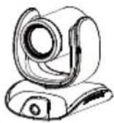 | 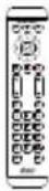 | 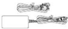 | 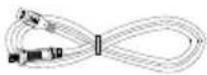 | 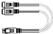 |
| HDMI Cable (3m) | Wall Mount Kit** | Screws for Mount | Drilling PaperQR Code Card | |
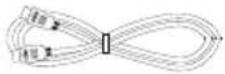 | 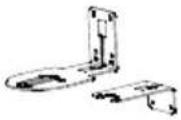 (A: 108 x 214 x 75 mmB: 75 x 135 x 50 mm) (A: 108 x 214 x 75 mmB: 75 x 135 x 50 mm) | 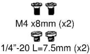 |   | |
| Speakerphone Unit | Speakerphone Power Adapter Power Cord* | USB 2.0 Cable | 3.5 mm Audio Cable | |
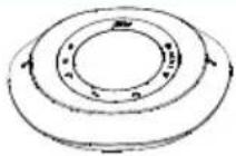 | 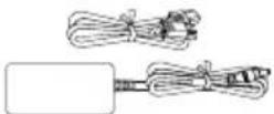 | 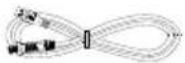 | 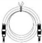 | |
* The power cord will vary depending on the standard power outlet of the country where it is sold.
Optional Accessories
| USB 2.0 Type-B to Type-A Cable (5m) | Mini DIN8 to D-Sub9 Cable | Foldable TV Mount | USB 3.1 Extender 10m/20m/30m |
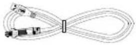 | 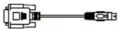 | 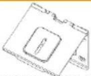 (201.37 x 151.5 x 160 mm) (201.37 x 151.5 x 160 mm) | 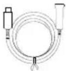 |
| Ceiling Mount** | |||
| (165 x 165 x 612 mm) | |||
*Optional Accessories will vary depending on the country where it is sold.
**This is a dual lens camera and doesn't support upside down installation. To mount on ceiling, please purchase ceiling mount from AVer.
Overview
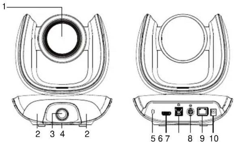
1 Optical Zoom Lens 6 HDMI Port**
2 IR Sensor 7 USB 3.1 Type B Port
3 AI Lens ^* 8 RS232 In/Out Port
4 Status LED 9 PoE Port***
5 Kensington Lock 10 DC 12V Power Jack
* AI Lens:
Users can see AI lens preview image in PTZApp 2, IP web page or HDMI out to check camera installation location.
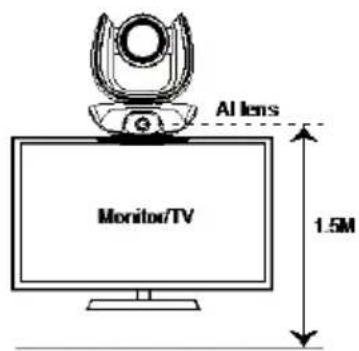
AI lens is used to detect participants within its 95 degree field of view to trigger optical zoom lens to track people in the room. Please don't put the camera on table because the AI lens view will be blocked. The suggested installation height is at least 1.5m.
** HDMI out streaming supports picture in picture (PIP) function. For more details, please refer to HDMI Connection on page 17.
*** Power over Ethernet (PoE) is compatible with IEEE 802.3at/802.3af. Please use a CAT 5e FTP cable (not included).
Camera LED Indicator
Solid blue: Power on
Solid red: Start-up
Solid orange: Only power cable connected
Solid blue: Video on
Solid white: USB cable is connected but camera doesn't have any streaming out
Gesture control
Blue light blinks for 2 seconds: Successfully wake up gesture control function by any valid gesture command.
Blue light blinks for 4 seconds: Camera recognizes a valid gesture command and start to action.
[Note]: The default of gesture control is off. Please enable it via PTZApp 2 or IP web page. The effective distance is up to 5-meter away from the camera. Please refer to page 45.
Speakerphone
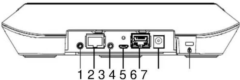
-
Phone in port
-
Speakerphone port (For extended speakerphone and microphone / Red cable)
-
Line out port
-
USB port
-
Ethernet port
-
Power jack
-
Kensington Lock
Speakerphone button
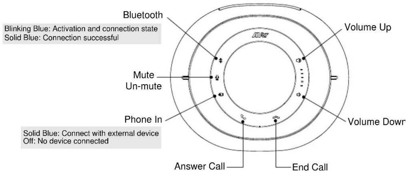
Speakerphone LED Indicator
| Button | LED Indicator | Status |
 | White light | Adjust the volume up and down. When adjusting the volume up and down, the volume LED indicator will light up in blue. |
 | Blue light | Touch to mute/un-mute the speakerphone volume. In mute status, the LED indicator will light up in red. |
 | Red light | Touch to hang up the call. |
 | Green light | Touch to answer the incoming call. |
 | ■ Blue light: Connects with external device■ White light: Temporarily disconnects the connection with the device■ Off: No connection with external devices | When the Phone in port connects with the device, the LED indicator will light up in blue. |
| [SWD3] | ■ Activate Bluetooth and connect with laptop/PC. | When connection is successful, the Bluetooth indicator will light up in Blue. |
Installation Camera
- Connect the camera to power outlet.
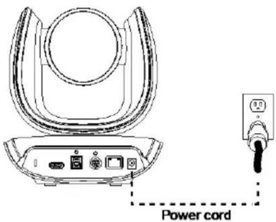
- Connect the necessary cables.
[Notes]
■ Secure the USB and RS232 cables with attached screws.
■ Make sure the cable is well connected to the connector on the camera before securing the cable.
![AVer VC550 - [Notes] - 1](/content/2026/05/905106/images/211761805379aabf883fed0d8e4a1fcabbe672f7ed134a4348e07c8504c2bbb5.jpg)
natural_image
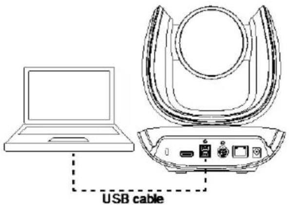
Technical line drawing of a mechanical device with internal components and directional arrows (no text or symbols)3. Connect the camera to the computer/laptop.
[Notes]
■ Use the USB 3.1 cable included in the package.
■ CAM550 has the USB 3.1 port which is USB 2.0 compatible.
Maximum resolution/fps for USB 2.0 and USB 3.1 port are shown below.
| USB 2.0 | USB 3.1 | HDMI | ||
| YUV | M-JPEG | YUV | M-JPEG | |
| - 640x480 or less resolution, up to 30fps- 720p, up to 10fps | - 1080p/60fps | - Up to 1080p/30fps- 720p/60fps | - Up to 4k/30fps- 1080p/60fps | 1080p/60fps1080p/30fps |
-
AI lens is used to detect participants within its 95 degree field of view to trigger optical zoom lens to track people in the room. Please don't put the camera on table because the AI lens view will be blocked. The suggested installation height is at least 1.5m.
-
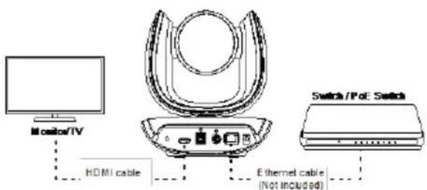
Connect Ethernet cable for IP streaming and remote camera control.
[Note]
■ To ensure stability of IP video streaming, please use CAT 5e FTP cable. (not included)
- Connect an HDMI cable to a TV monitor to have instant live video.
[Notes]
■ HDMI port only supports 1080p resolution.
■ If you select RTSP/RTMP resolution up to 4k resolution, the HDMI out streaming will be disabled.
Speakerphone
- Connect the speakerphone to a power outlet.
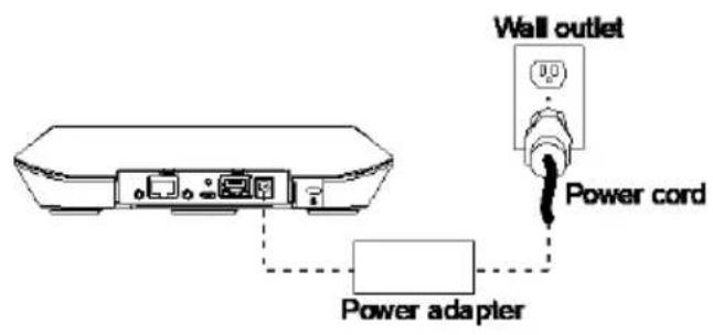
- Connect the speakerphone to the laptop/PC.
[Note]
■ Use the USB cable that is included in the package.
■ Remove the back cover for cable installation.
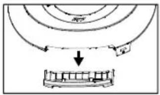
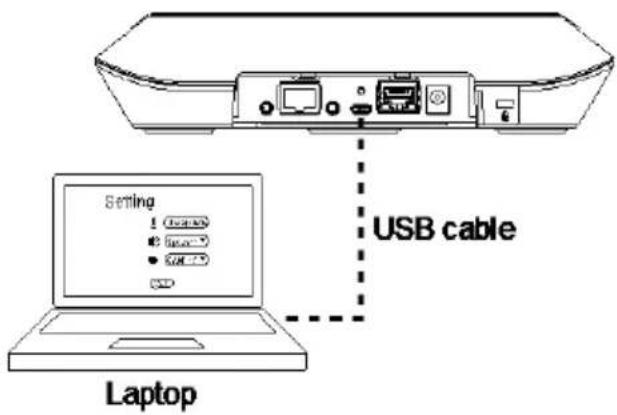
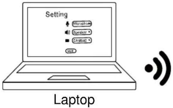
Or, enable the Bluetooth function on the laptop/PC to make a wireless connection.
![AVer VC550 - [Note] - 4](/content/2026/05/905106/images/3cf34c413b9c1e8856beaaa29e2ecdd0af32bc598ee454ff52e8dfcec03a4740.jpg)
natural_image
Diagram of concentric rings with signal waves and a starburst symbol, no text or labels present[Note]
■ Press ✪ on the speakerphone to activate Bluetooth and connect with laptop/PC.
■ When connection is successful, the Bluetooth indicator will light up in Blue.
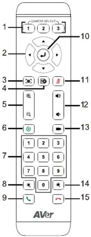
Remote Control
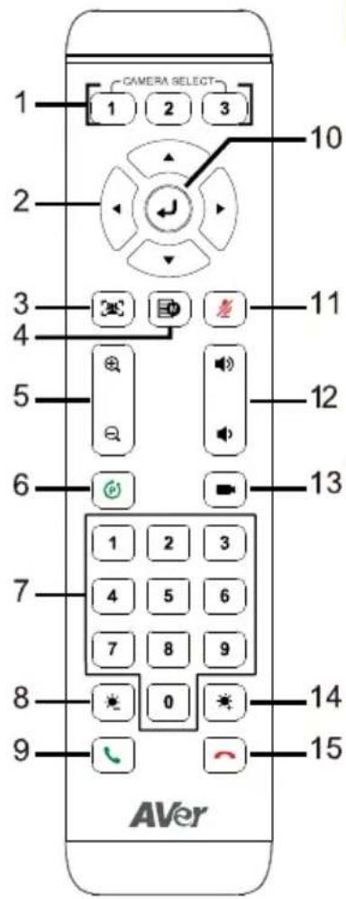
Name
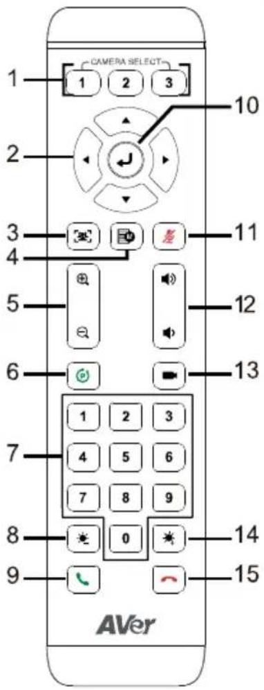
- Camera Select
Function
One remote control can control up to 3 AVer USB cameras. To bind cameras, please use PTZApp 2 or access IP web page to set it up.
[Note] The default is Off. If you don't do any binding, no matter you press camera 1 or 2, 3 button on the remote control, you can control all the AVer USB cameras around you.
-
Camera Directional Control
-
SmartFrame
Use the directional buttons on the remote to control the direction of the camera. Press the directional button to move the camera or press and hold to continuously pan or tilt.
One-click automatic field of view adjustment to fit all participants. Press for 1\~2 seconds to switch the SmartFrame function among Manual Framing/Auto Framing/Preset Framing modes. A message (as figures shown) will display on the screen to indicate the mode while using HDMI out function.
Manual Framing
Auto Framing
Preset Framing
While in Auto Framing mode, or doing one-click manual frame, an icon message (as figure shown) will display on the upper left screen to indicate that the framing action is triggered. The icon will appear 2\~3 seconds on the screen while using HDMI out function. Once the framing process is done, it will disappear. If you don't
want to see the icon display, please go to PTZApp 2, find "On Screen Menu" function and select "Off".
[Notes]
■ Default is Manual Framing. SmartFrame deploys face and body detection technology. People wearing masks and side facial profiles can still be detected. The maximum detection distance is 7\~10 meters away from the camera.
■ Camera will track people while moving. It will start to focus and zoom in once people stop moving for 1\~5 seconds, depending on the framing speed you choose. The default framing speed is "Middle" speed. "High" speed is more suitable for one person tracking.
■ Preset Framing: Set up preset points in advance (Only for Preset points 1\~9. Preset 0 is for home position). Camera tracks one presenter and shoots the preset areas instead of focusing and zooming into presenter. The preset areas must be within the viewing area of AI lens.
| 4. OSD Menu | Short press the button to pull up OSD menu while using HDMI out function. Hold it for 1 sec. to select camera layout (PIP). |
| 5. Zoom In/Out | Increase/Decrease the camera zoom. |
| 6. Preset | The Preset button on the remote serves 2 functions. |
- Preset Position/Number Buttons
To Save a Preset – Move camera to desired position. Press and hold the preset button until you receive the save message on the screen. Select preset position button 0-9 to store the current camera position. Repeat steps if needed.
To Load a Preset - Press the preset button and preset position button 0-9 to load a saved camera position. Repeat steps if needed.
Preset position buttons are used in conjunction with the Preset button to save positions. There are a total of 10 presets.
Press the preset button first and then press 0\~9 for the camera to move to the saved position.
[Notes]
■ Press and hold the number button "fbr 1 second to turn on or off the WDR function. WDR function is suggested to be used in high contrast background environment to enhance the dark area. The frame rate will drop to 30 fps or lower. If the light condition is normal, this function will cause image blur.
■ Press and hold the number button "For 1 second to turn on or off the SmartFrame function.
■ Press and hold the number button " for 1 second to enable or disable RTMP streaming function.
■ Press and hold the number button
“”for 1 second to force camera to enter sleep mode. This will end any video streaming. To wake up the camera, press the button or any directional button for 1 second. This mode is not functional while USB streaming is on.
| 8. Brightness - | Decrease the brightness of the video image. |
| 9. Call/Answer | Answer a call or start a call. Not supported for CAM550. |
| 10. Enter | Click the button to show current AI mode while using HDMI out function. |
| 11. Mute/Un-mute Speakerphone | Mute/Un-mute the speakerphone.* Need to install PTZApp2 to support. |
| 12. Volume Up/Down | Adjust volume up or down.* Need to install PTZApp2 to support. |
| 13. Preset Hot Key | After saving positions, press to move the camera to the preset position the user has set. |
| 14. Brightness + | Increase the brightness of the video image. |
| 15. Hang Up | End the call. Not supported for CAM550. |
Pan and Tilt Angle
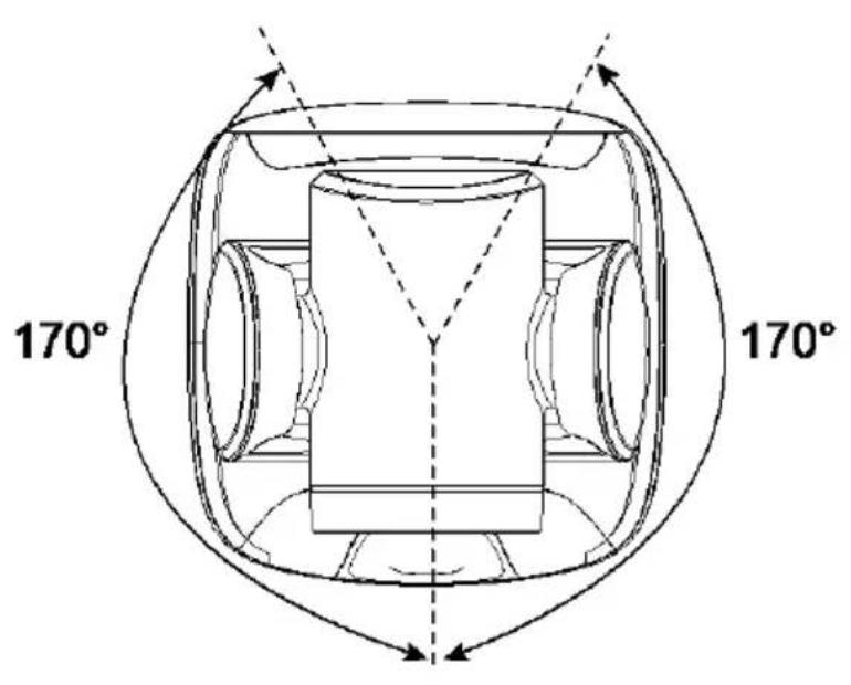
Device Connection
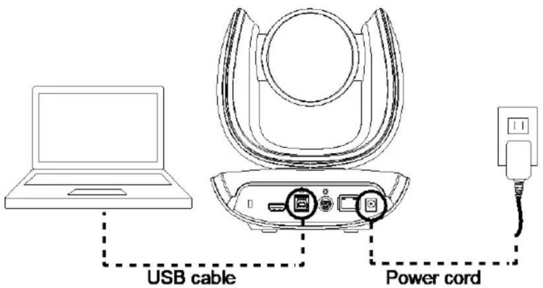
- Use USB cable to connect the CAM550 to your PC/laptop (refer to diagram above).
- Connect the power to the CAM550; power indicator will light up and camera head will rotate.
- Install PTZApp 2 on laptop or PC that is connected with CAM550. The app can be used to adjust and setup the parameters of the camera (refer to the section of PTZApp 2).
- To make a call, run your video application (Zoom, Microsoft ^ Teams, Skype for Business, Skype, Google Meet, Intel ^ Unite ^TM , RingCentral, BlueJeans, V-Cube, LiveOn, CyberLink U Meeting ^ , TrueConf, Adobe Connect, Cisco WebEx ^ , Fuze, GoToMeeting ^TM , Microsoft ^ Lync ^TM , Vidyo, vMix, WebRTC, Wirecast, XSplit, etc.). Select CAM550 as your video device.
- AI lens is used to detect participants within its 95 degree field of view to trigger optical zoom lens to track people in the room. Please don't put the camera on table because the AI lens view will be blocked. The suggested installation height is at least 1.5 ~m . The camera's working distance is 1.5 ~m . People stand too close (within 1 ~m away) to the camera may cause bad framing performance.
- Please note that the angle of AI lens is larger than PTZ camera. If people at two sides of meeting room sit within AI lens view but out of PTZ lens' widest angle, they won't be framed and appear in the view of PTZ lens successfully. When you see the warning message, please come closer to make sure people at two sides can be within PTZ camera's viewing angle. "You are outside of the PTZ Lens' viewing angle. Please come closer."
[Notes]
■ Use the USB 3.1 cable included in the package.
■ CAM550 has the USB 3.1 port which is USB 2.0 compatible.
Maximum resolution/fps for USB 2.0 and USB 3.1 port are shown below.
| USB 2.0 | USB 3.1 | HDMI | ||
| YUV | M-JPEG | YUV | M-JPEG | |
| - 640x480 or less resolution, up to 30fps- 720p, up to 10fps | - 1080p/60fps | - Up to 1080p/30fps- 720p/60fps | - Up to 4k/30fps- 1080p/60fps | 1080p/60fps1080p/30fps |
Power Connection
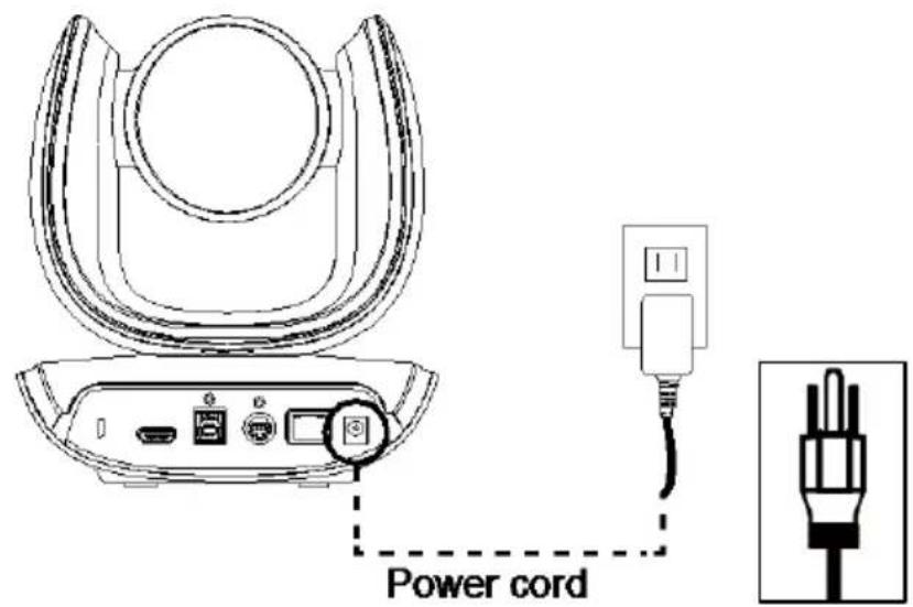
The power supply can be plugged into the wall outlet or drawn from PoE switch (Ethernet).
Wall outlet
PoE
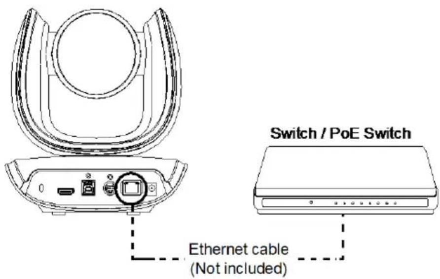
[Note] To ensure stability of IP video streaming, please use CAT 5e FTP cable (not included).
HDMI Connection
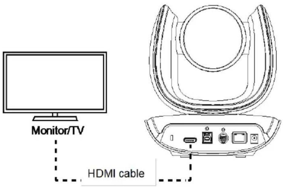
Connect with TV or monitor through the HDMI port to display camera video on the screen.
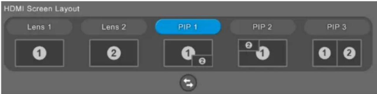
Hold button for 1 second on remote control to call out the screen layout option. Select the camera image layout firstly. The default is PIP1, showing optical zoom lens image as main screen and AI lens image as small view. Under this layout, you can switch two cameras by pressing Up/Down on remote control.
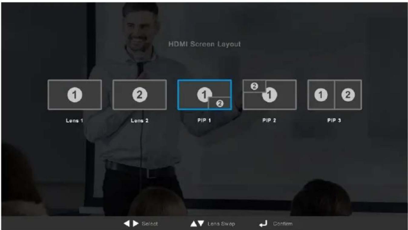

Lens 1 The PTZ camera focuses on speaker
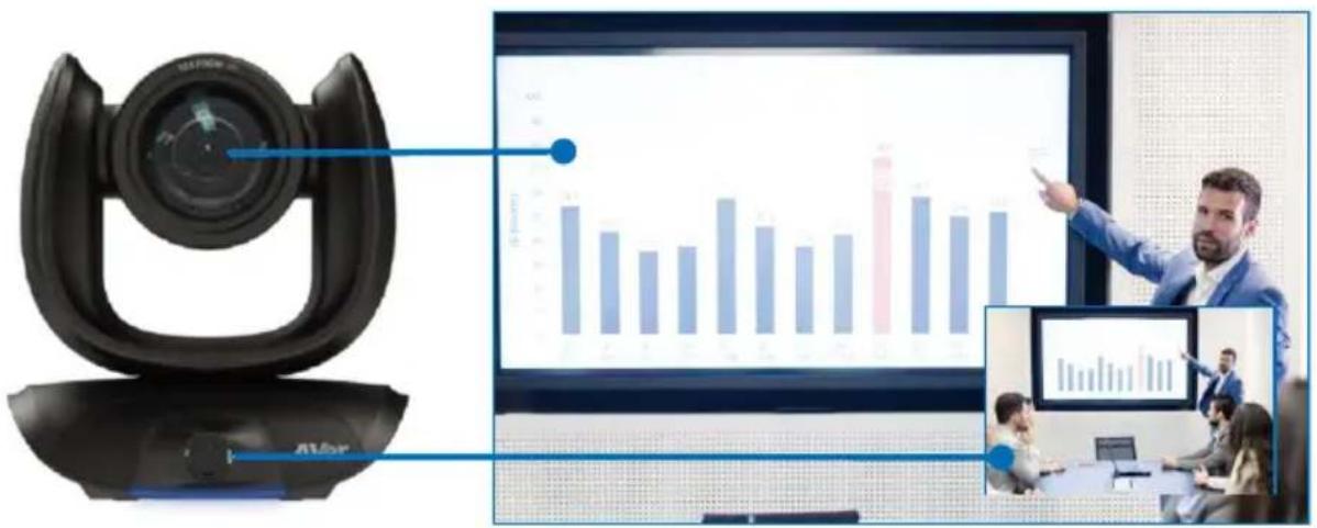
Lens 2 Shows all participants
After choosing the image layout, short press the OSD menu button and then the setting page will show up. Press right direction button to enter and configure the parameters of the camera. Short press the OSD button twice or hold it for 1 sec. to leave. The HDMI OSD setting function is the same as Web configuration interface. Please refer Web Settings on page 37 for more details.
RS232 Connection
■ Camera RS232 Port Pin Definition
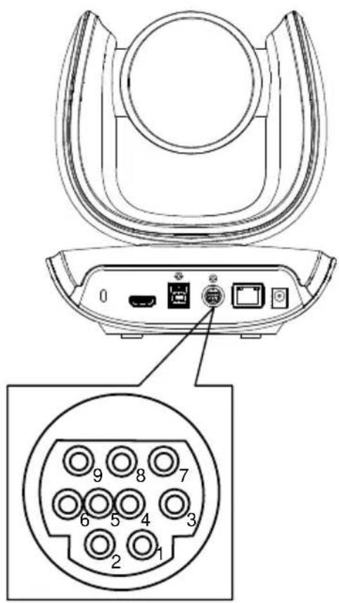
| Function | Mini DIN9 PIN # | I/O Type | Signal | Description |
| VISCA IN | 1 | Output | DTR | Data Terminal Ready |
| 2 | Input | DSR | Data Set Ready | |
| 3 | Output | TXD | Transmit Data | |
| 6 | Input | RXD | Receiver Data | |
| VISCA OUT | 7 | Output | DTR | Data Terminal Ready |
| 4 | Input | DSR | Data Set Ready | |
| 8 | Output | TXD | Transmit Data | |
| 9 | Input | RXD | Receiver Data | |
| 5 | --- | --- | Not connect |
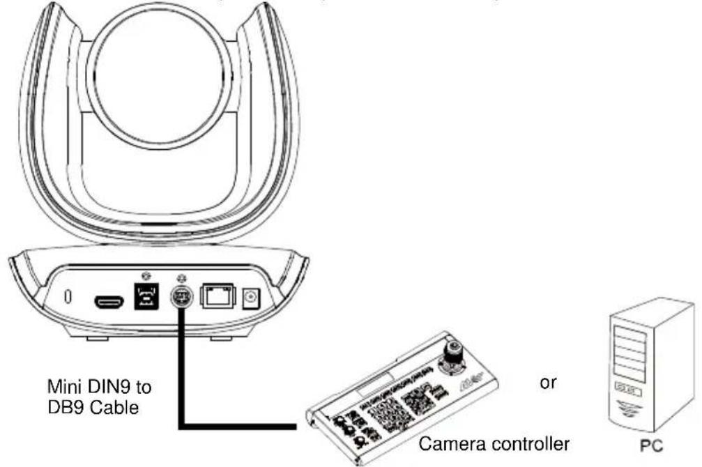
Computer/Keyboard Controller and Camera Connection
Direct Connection
If users do not use AVer RS232 adapter cable, please refer to the pin connection shown below.
| Camera(Mini DIN9) | Camera controller or PC(DB9) |
| 1. DTR (IN) | 1. DCD |
| 2. DSR (IN) | 2. RXD |
| 3. TXD (IN) | 3. TXD |
| 6. RXD (IN) | 4. DTR |
| 7. DTR (OUT) | 5. GND |
| 4. DSR (OUT) | 6. DSR |
| 8. TXD (OUT) | 7. RTS |
| 9. RXD (OUT) | 8. CTX |
| 9. RI |
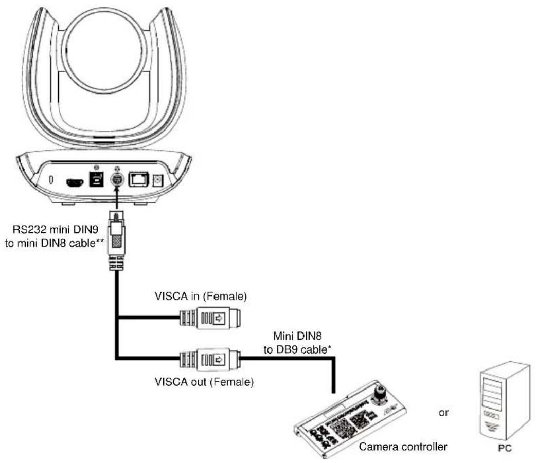
flowchart
graph TD
    A["RS232 mini DIN9 to mini DIN8 cable**"] --> B["VISCA in (Female)"]
    A --> C["VISCA out (Female)"]
    B --> D["Mini DIN8 to DB9 cable*"]
    C --> D
    D --> E["Camera controller"]
    E --> F["PC"]
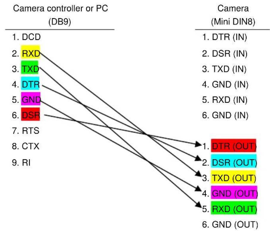
other
| Camera controller or PC (DB9) | Connection Type | | ------------------------------ | --------------- | | DCD | DTR (IN) | | RXD | DSR (IN) | | TXD | TXD (IN) | | DTR | GND (IN) | | GND | RXD (IN) | | RS | GND (IN) | | RTS | DTR (OUT) | | CTX | DSR (OUT) | | RI | TXD (OUT) | | | GND (OUT) | | | RXD (OUT) | | | GND (OUT) |* Mini DIN8 to D-Sub9 (DB9) cable 064AOTHERBPK is an optional item.
** RS232 mini DIN9 to mini DIN8 Cable Pin Definition
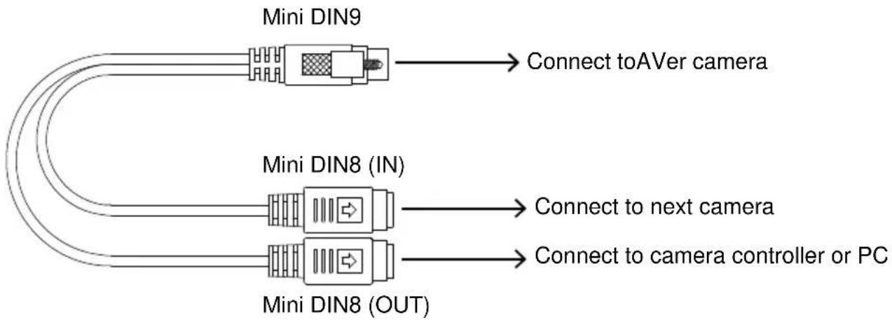
flowchart
graph LR
    A["Mini DIN9"] --> B["Connect to AVer camera"]
    C["Mini DIN8 (IN)"] --> D["Connect to next camera"]
    C --> E["Connect to camera controller or PC"]
    F["Mini DIN8 (OUT)"] --> E
Mini DIN8 Pin Definition
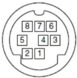
| No. | Pin |
| 1 | DTR |
| 2 | DSR |
| 3 | TXD |
| 4 | GND |
| 5 | RXD |
| 6 | GND |
| 7 | NC |
| 8 | NC |
■ Camera Cascade Connection
Direct Connection
If users do not use AVer RS232 adapter cable, please refer to the pin connection shown below for cascading cameras.
Total can connect up to 7 cameras.
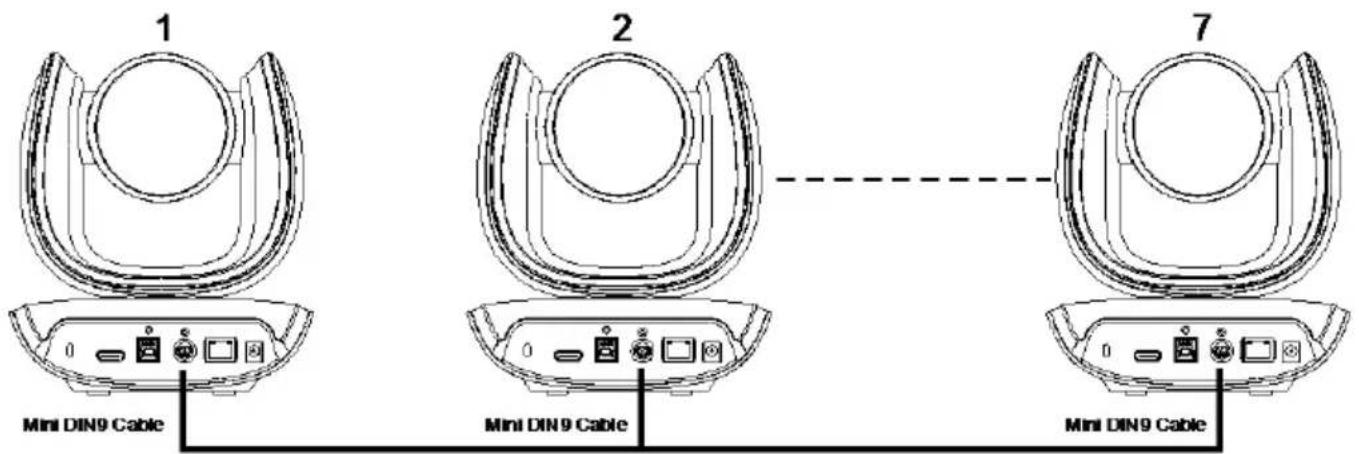
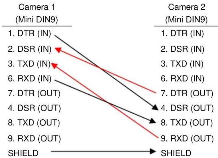
flowchart
graph TD
    A["Camera 1 (Mini DIN9)"] --> B["1. DTR (IN)"]
    A --> C["2. DSR (IN)"]
    A --> D["3. TXD (IN)"]
    A --> E["6. RXD (IN)"]
    A --> F["7. DTR (OUT)"]
    A --> G["4. DSR (OUT)"]
    A --> H["8. TXD (OUT)"]
    A --> I["9. RXD (OUT)"]
    J["Camera 2 (Mini DIN9)"] --> K["1. DTR (IN)"]
    J --> L["2. DSR (IN)"]
    J --> M["3. TXD (IN)"]
    J --> N["6. RXD (IN)"]
    J --> O["7. DTR (OUT)"]
    J --> P["4. DSR (OUT)"]
    J --> Q["8. TXD (OUT)"]
    J --> R["9. RXD (OUT)"]
    S["SHIELD"] --> T["SHIELD"]
Total can connect up to 7 cameras.
To facilitate the camera cascade, users can use AVer RS232 adapter cable.
Connect camera with AVer mini DIN9 to mini DIN8 adapter cable. Connect the mini DIN8 female side to male mini DIN8 Visca cable (Users have to buy it in the market) and then connect AVer mini DIN9 to mini DIN8 adapter cable again to connect to next camera.
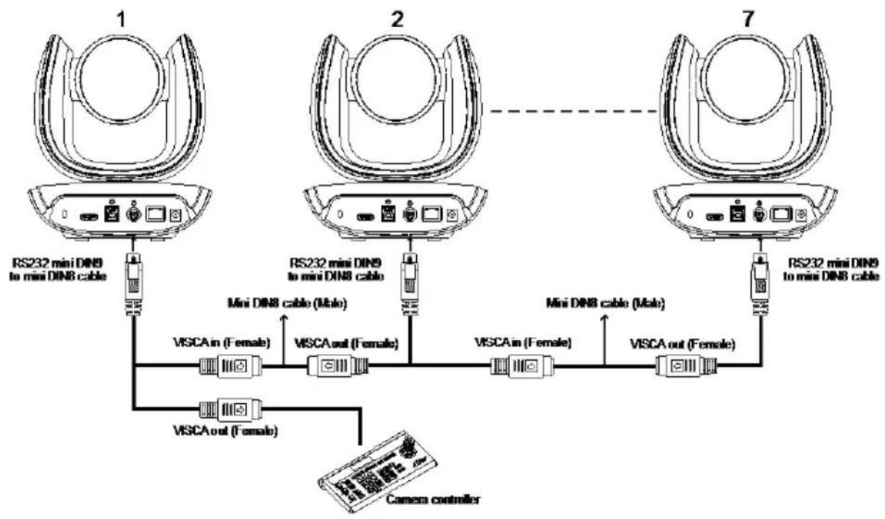
flowchart
graph TD
    A["1: RS232 mini DIN9 to mini DIN8 cable"] --> B["2: RS232 mini DIN9 to mini DIN8 cable"]
    B --> C["7: RS232 mini DIN9 to mini DIN8 cable"]
    B --> D["Mini DIN8 cable (Male)"]
    B --> E["Mini DIN8 cable (Male)"]
    D --> F["VISCA in (Female)"]
    E --> G["VISCA out (Female)"]
    F --> H["VISCA out (Female)"]
    G --> I["VISCA out (Female)"]
    H --> J["Camera controller"]
    I --> J
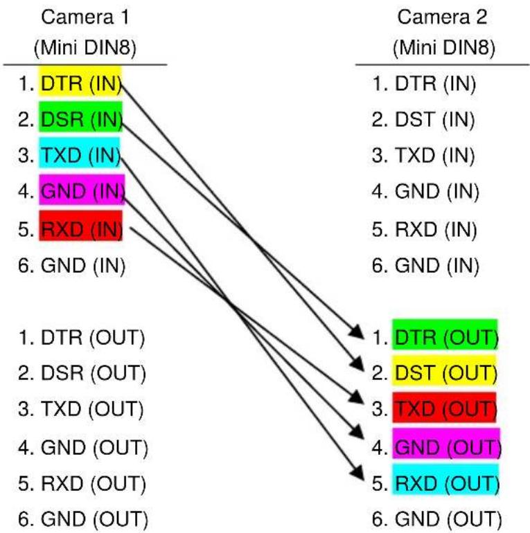
flowchart
graph TD
    A["Camera 1 (Mini DIN8)"] --> B["1. DTR (IN)"]
    A --> C["2. DSR (IN)"]
    A --> D["3. TXD (IN)"]
    A --> E["4. GND (IN)"]
    A --> F["5. RXD (IN)"]
    A --> G["6. GND (IN)"]

    H["Camera 2 (Mini DIN8)"] --> I["1. DTR (IN)"]
    H --> J["2. DST (IN)"]
    H --> K["3. TXD (IN)"]
    H --> L["4. GND (IN)"]
    H --> M["5. RXD (IN)"]
    H --> N["6. GND (IN)"]

    O["Camera 2 (Mini DIN8)"] --> P["1. DTR (OUT)"]
    O --> Q["2. DST (OUT)"]
    O --> R["3. TXD (OUT)"]
    O --> S["4. GND (OUT)"]
    O --> T["5. RXD (OUT)"]
    O --> U["6. GND (OUT)"]
Wall Mount Installation
- Use the drilling paper included in the package to drill the holes in the wall where the user wants to mount the camera.
![46.00[1.81] Ø 5.50[Ø 0.22] 51.00[2.01] P/N: 303AU340-AGR](/content/2026/05/905106/images/32c67009453ea13408d604e3ce74b6cc56a73edde6861b4f7f8f477a6dcbd32c.jpg)
- Use the screws (not included) to secure the L-mount bracket on the wall.
Screw
For Cement wall: M4 x20mm self-tapping screws (x4) + Plastic conical anchor For Wooden wall: M4 x20mm self-tapping screws (x4)
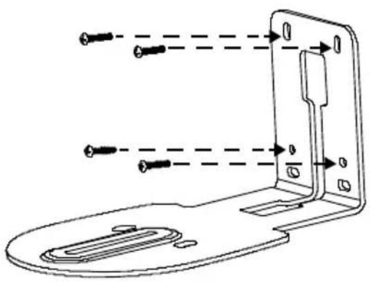
natural_image
Technical line drawing of a device with multiple screw holes and mounting brackets (no text or symbols)- Then, assemble the L-mount brackets A + B with screws (included in package).
Screw size: 4 x8.5m (x2)
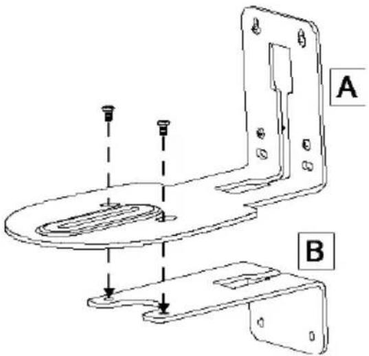
- After assembling the L-mount brackets, use the screws (not included) to secure the lower part of L-mount brackets on the wall.
Screw
For Cement wall: M4 x20mm self-tapping screws (x2) + Plastic conical anchor
For Wooden wall: M4 x20mm self-tapping screws (x2)
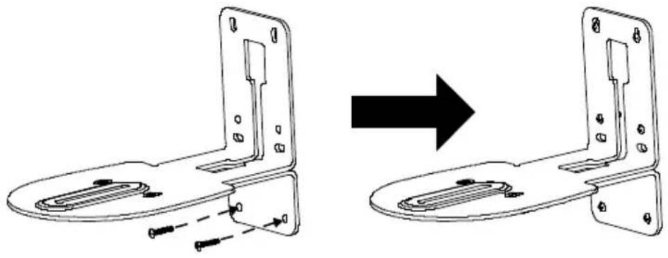
natural_image
Technical line drawing of a mechanical bracket assembly before and after modification (no text or symbols)- Pass the cables through the hole on the L-mount bracket and connect the cables to corresponding connection ports.
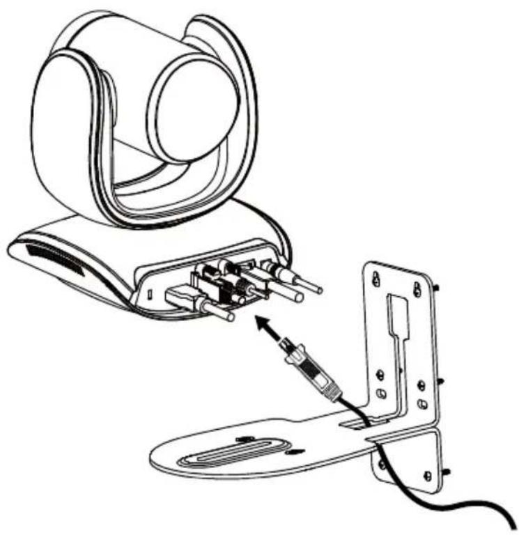
natural_image
Line drawing of a medical or electronic device with attached components, showing internal wiring and a close-up of the connector (no text or symbols present)- Use the remaining screws (included in package) to secure the camera on the L-mount bracket.
Screw: 1/4"-20L=7.5mm (x2)
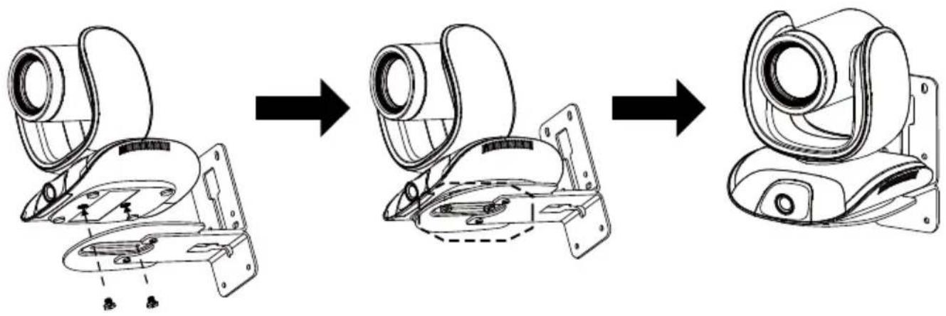
flowchart
graph LR
    A["Front-mounted camera with lens and mounting bracket"] --> B["Assembly part"]
    B --> C["After assembly"]
    C --> D["Final rear-mounted device"]
Ceiling Mount Installation (Optional)
You can use the optional ceiling mount accessories to mount the camera to the ceiling.
Package Content
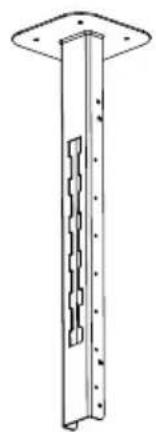
natural_image
Technical line drawing of a vertical structural component with a central slot and flange (no text or symbols)Mount bracket x 1 (165 x 165 x 612 mm)
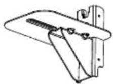
Camera bracket x 1
(170 x 260 x 194 mm)

Back cover x 1
(54 x 22 x 525 mm)
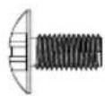
Screw (M4*8) x 8
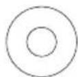
Washer x 8
(ø 10.0 x 1.2 mm)
Dimension
Unit=mm
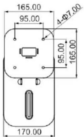
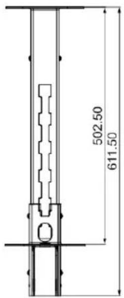
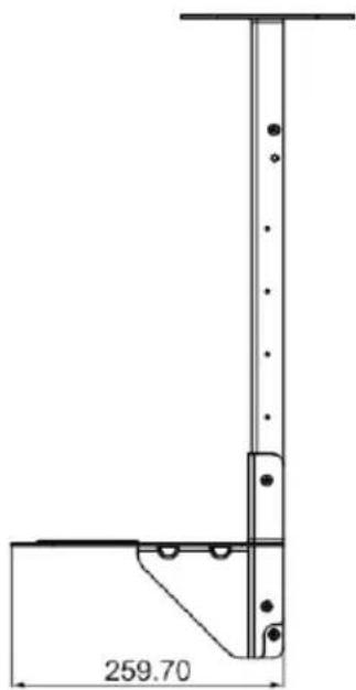
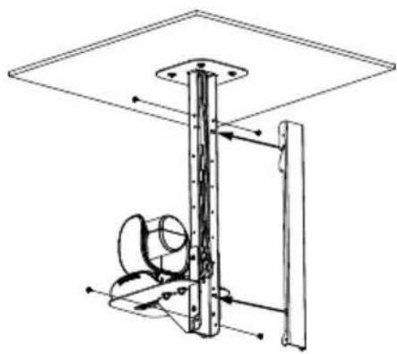
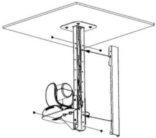
To mount the camera to the ceiling:
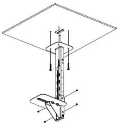
- Drill the hole on the ceiling. Use screw to secure the mount bracket on the ceiling.
Screw: 4 M6 x 50mm (Not included in package)
- Use the supplied screws with washers to secure the camera bracket to the mount bracket.
Screw: 4 M8 x 4 + 4 Washer
- Connect all cables on the camera and pass all cables out through the hole on the mount bracket. Then, secure the camera on the camera bracket.
Screw: 2 UNC-1/4"-20 (Not included in package)
natural_image
Technical line drawing of a mechanical device with no visible text or symbols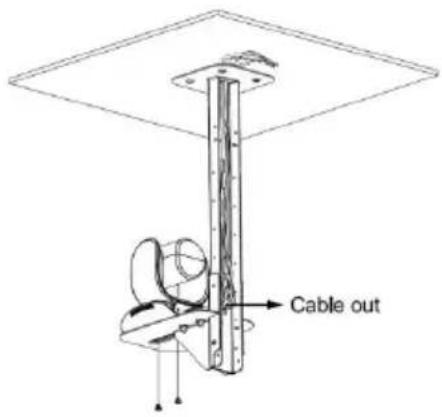
-
Organize all cables to go out from top or bottom of mount bracket.
-
Then, secure the back cover with screws and washer.
Screw: 4 M8 x 4 + 4 Washer
natural_image
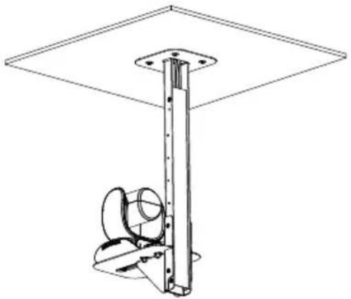
Technical line drawing of a mechanical assembly with no visible text or symbols- Completed.
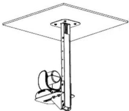
natural_image
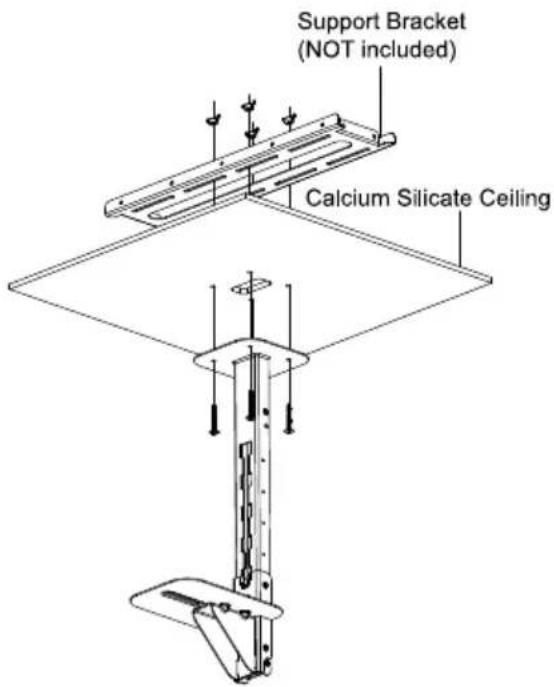
Technical line drawing of a mechanical support structure with a flat plate and vertical rod (no text or symbols)To mount the camera to the calcium silicate ceiling:
-
Please purchase support bracket for supporting camera mount bracket on calcium silicate ceiling. Then, secure the support bracket on the light steel frame structure.
-
Drill the hole on the calcium silicate ceiling. Open a hole on the calcium silicate ceiling to allow camera cables to pass through.
-
Then, secure the mount bracket, calcium silicate ceiling and support bracket together.
Screw: 4 Wingnut + 4 M6x50mm (Not included in package)
- Use the supplied screws with washers to secure the camera bracket to the mount bracket.
Screw: 4 M8 x 4 + 4 Washer
-
Connects all cables on the camera and pass all cables through the hole on the mount bracket. Organize all cables to pass through the hole on the ceiling. Also, the cable can go out from top or bottom of mount bracket.
-
Then, secure the camera on the camera bracket.
Screw: 2 UNC-1/4"-20 (Not included in package)
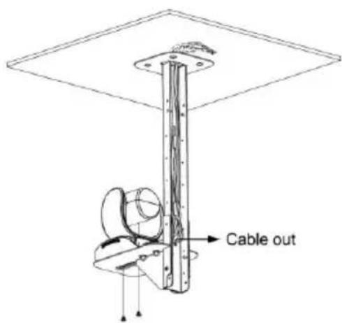
- Next, secure the back cover with screws and washer.
Screw: 4 M 8 × 4 + 4 Washer
natural_image
Technical line drawing of a mechanical assembly with no visible text or symbols- Completed.
natural_image
Technical line drawing of a mechanical support structure with mounting flange and base mount (no text or symbols)Secure the Cables
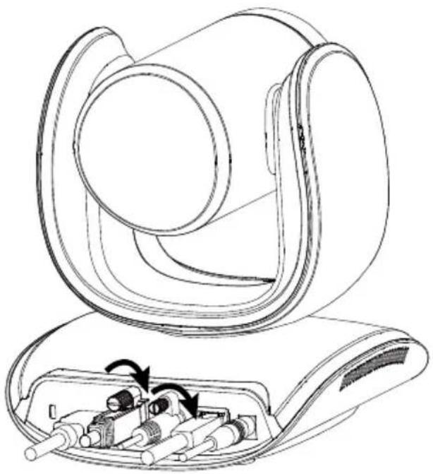
The USB and RS232 cables have a screw on the cable for securing cable on the camera.
Install the cable first and tighten the screw to secure the cable.
[Note] Make sure the cable is well connected to the connector on the camera before securing the cable.
natural_image
Technical line drawing of a mechanical device with internal components and directional arrows (no text or symbols)Make a Video Call
A computer is required to use this device.
- Make sure all devices (CAM550, laptop/PC, TV/monitor) are well connected and powered on.
- Run your video application (Zoom, Microsoft ^ Teams, Skype for Business, Skype, Google Meet, Intel ^ Unite ^TM , RingCentral, BlueJeans, V-Cube, LiveOn, CyberLink U Meeting ^ , TrueConf, Adobe Connect, Cisco WebEx ^ , Fuze, GoToMeeting ^TM , Microsoft ^ Lync ^TM , Vidyo, vMix, WebRTC, Wirecast, XSplit, etc.) on your PC or laptop.
- Set the CAM550 as your primary camera, and the FONE540 as your primary microphone and speaker device in your application. (Please consult your application setup guide for details).
- Ready to make a video call.
[Note] The CAM550 is a plug-and-play conference camera. The system requires no special drivers. The system requires no special drivers. For advanced setting and firmware update, please download
PTZApp 2. For information on how to install and use the PTZApp 2, refer to the PTZApp 2 section in this user manual.
Make a Connection through the Browser
CAM550 has an Ethernet port for IP streaming and allows administrators to remotely control and set up the camera via an internet access. Moreover, CAM550 also supports RTSP and RTMP functions. For more details, please contact our technical support.
- Make sure the CAM550 has an internet access connection.
- Launch PTZApp 2* (PTZ) and connect CAM550 to PC with USB cable. The camera default IP address is 192.168.1.168.
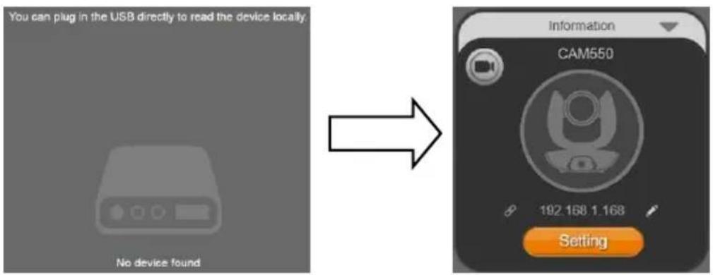
[Note] The browser supports:
- Chrome: version 76.x or above
- Firefox: version 69 or above
- IE: Doesn't support
- Click pencil icon (☐) to edit IP address**.
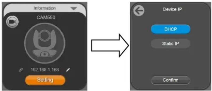
flowchart
graph LR
    A["Information CAM550"] --> B["Setting"]
    B --> C["Device IP"]
    C --> D["DHCP"]
    C --> E["Static IP"]
    C --> F["Confirm"]
- Click weblink icon (8) to launch Chrome page. Please enter the password (default password is aver4321). User will be asked to set a new account and password. (Please enter PTZApp 2 to reset password back to default while password is forgotten.)
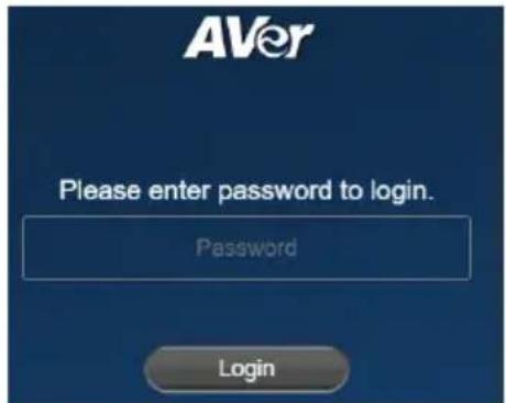
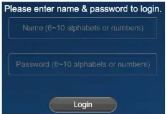
-
After editing IP address, user can access web settings of the camera with only Ethernet cable connection. Unplug the USB cable.
-
The main web screen is displayed as below.
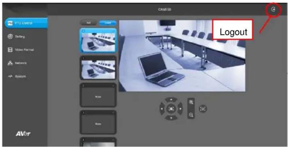
* For information on how to install and use the PTZApp 2, refer to the PTZApp 2 section in this user manual.
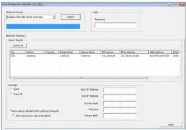
** To support IP address changes in groups, user can download AVer IP Finder app.
- Download the IP Finder from https://www.aver.com/download-center (Global), https://www.avereurope.com/download-center (Europe), or https://www.averusa.com/business/support (USA).
- Run the IP Finder.
- Click "Search", and all available devices will be listed on the screen.
- Select a camera from the list. The corresponding fields of IP address will display.
- To change the IP address of camera, user can select "DHCP" or "Static IP".
The DHCP should get the IP address from local dynamic IP sever. The static IP, user can enter the specific IP address. Click "Apply" to apply the setting to the camera. The password is required (default password is aver4321).
- Click "Search" button to re-scan the camera.
- Double-click on the IP address of camera from the list can connect to camera through the browser.
- Enter the default password (aver4321) to login to Web setup screen.
Web Settings
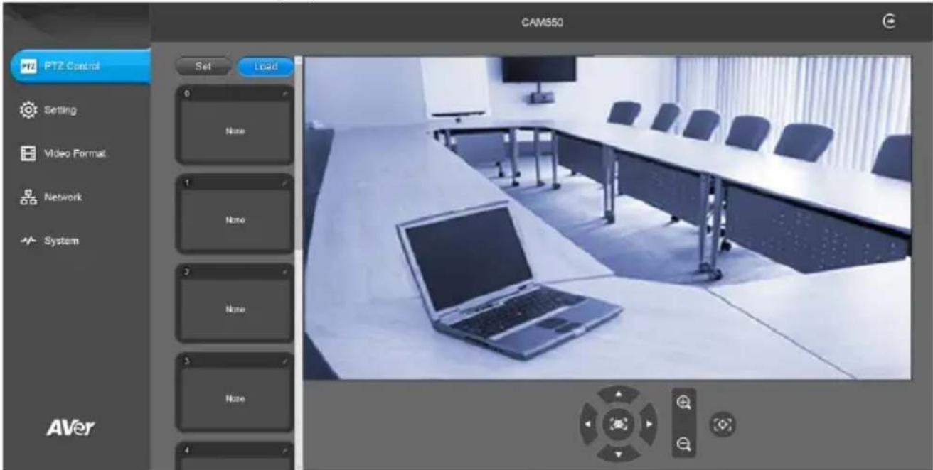
CAM550 supports Ethernet connection; users can enter the IP address into the web browser to connect to the camera for detail settings.
First Time Login
To find the IP address of the camera, please refer to "Make a connection through the Browser" section.
- Open the browser on your laptop/PC and enter the IP address of the camera.
- Enter the password at login screen. The default password is "aver4321".
- The main web screen is displayed.
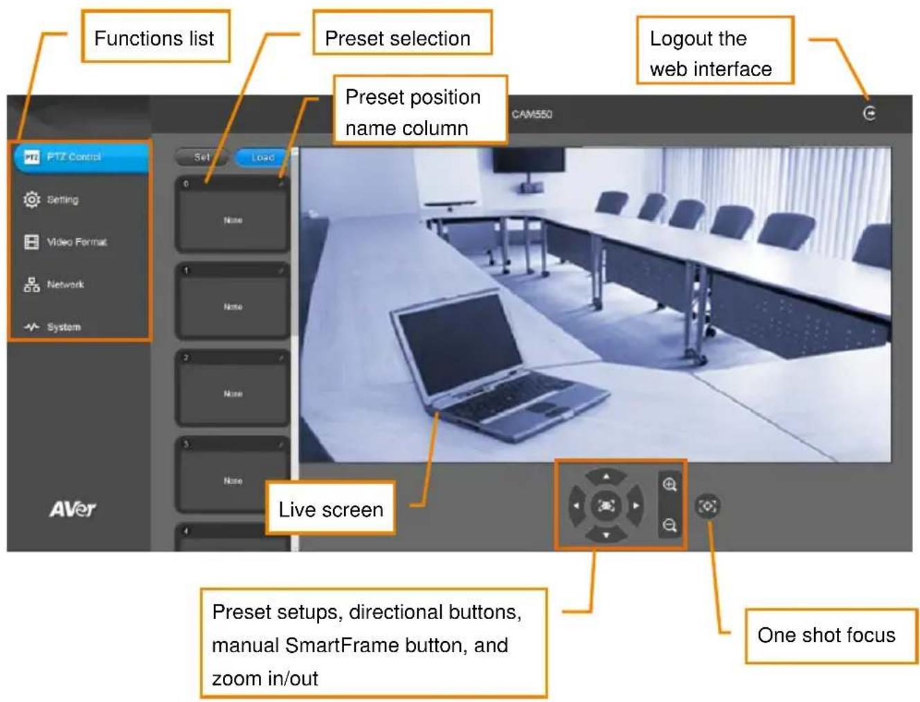
Live Screen Operation
User can control the camera direction, zoom in/out, and preset selection.
[Notes]
■ The system will force the previous login to log out, when there is a second login.
If the web page is idle without any request for more than 4 hours, user will be logged out.
■ The resolution of live screen is 1280x720 / 5fps.
Set Up the Preset
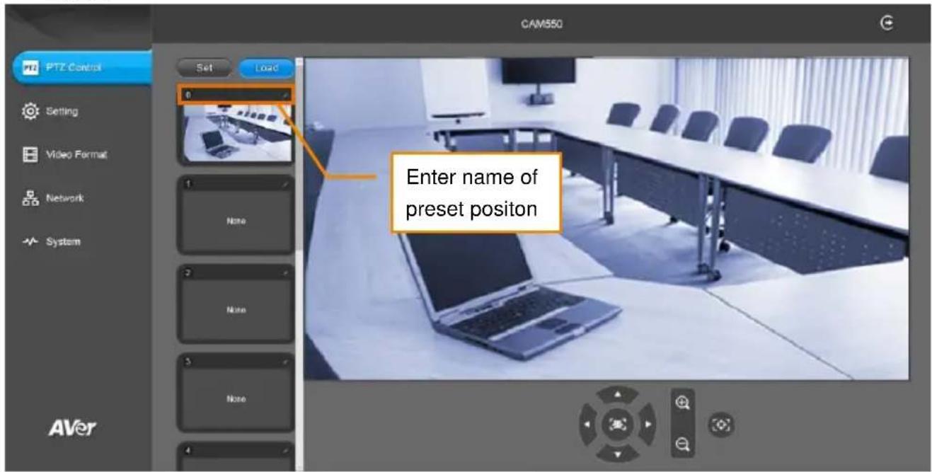
User can set 10 preset positions.
- In live screen, use ▲, ▼, ◀, ▶ and zoom in/out buttons to adjust the camera screen view to desired position.
- Select "Set" button and click on the preset number to save the preset. The system will capture the preset screen view and display in preset number frame.
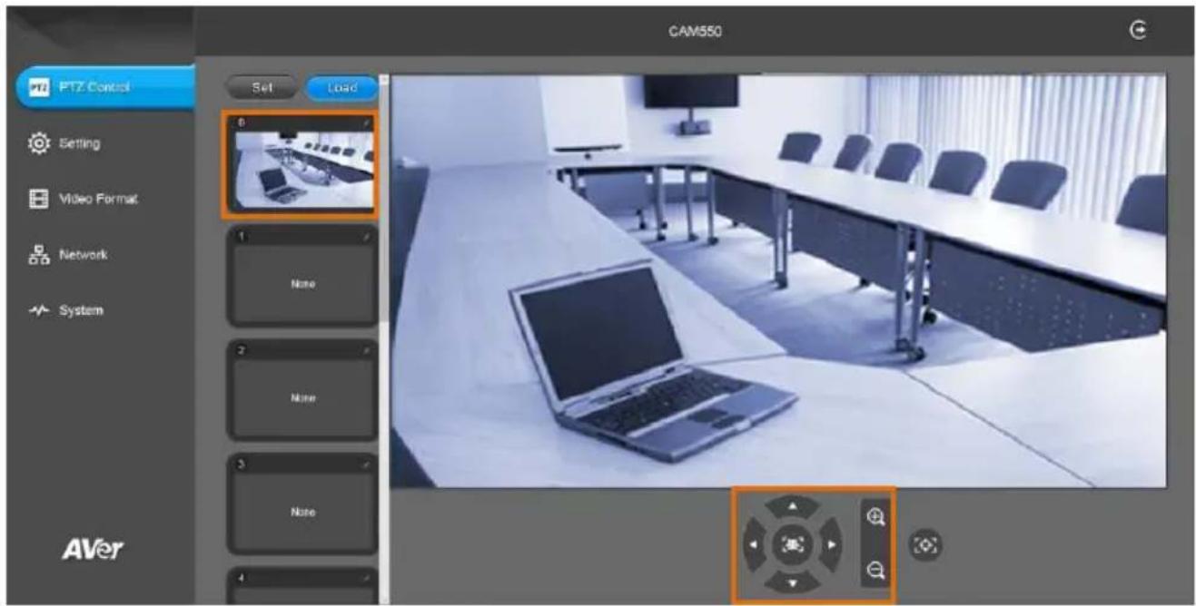
- Select icon to edit name of preset frame. Click other Web interface to save the name edited.
-
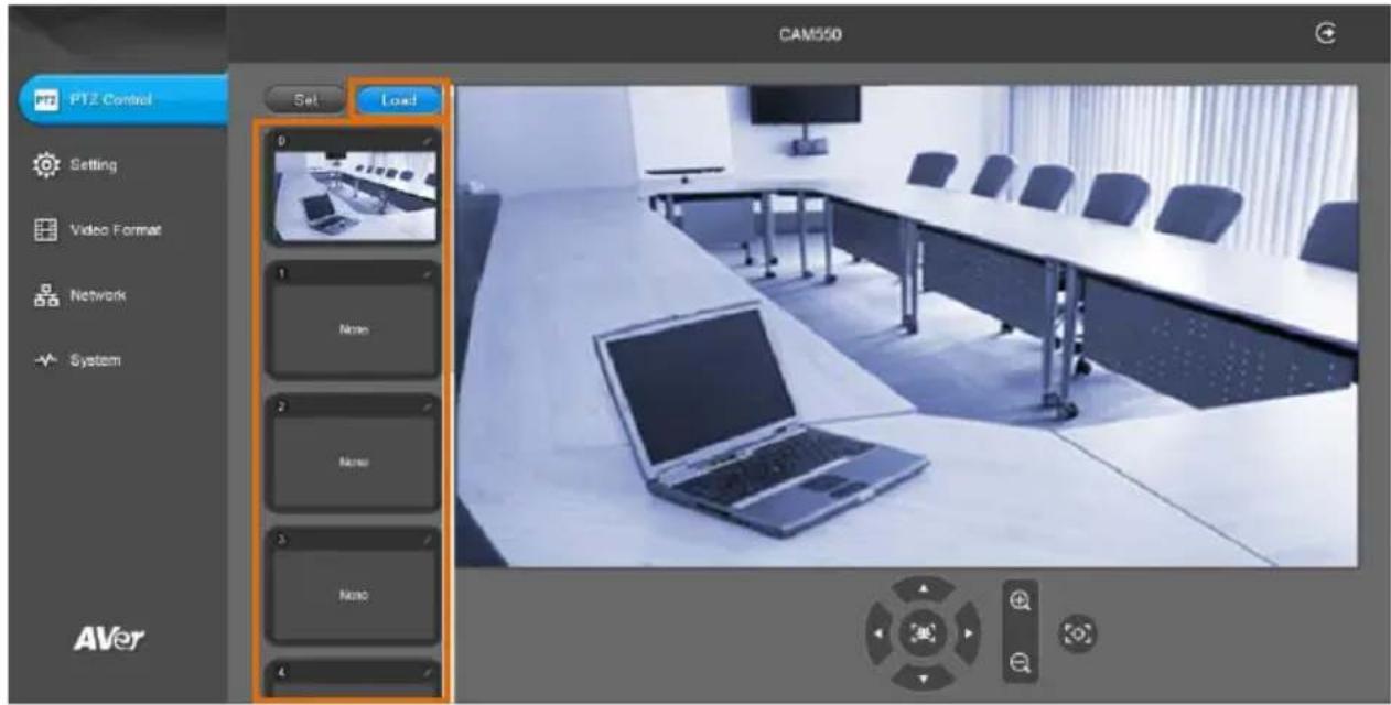
To set another preset, repeat the above steps.
-
After setting up the preset positions, you can start performing the function. Select the "Load" button and then click on the preset numbers, the live screen will move to the preset screen view.
Camera Settings
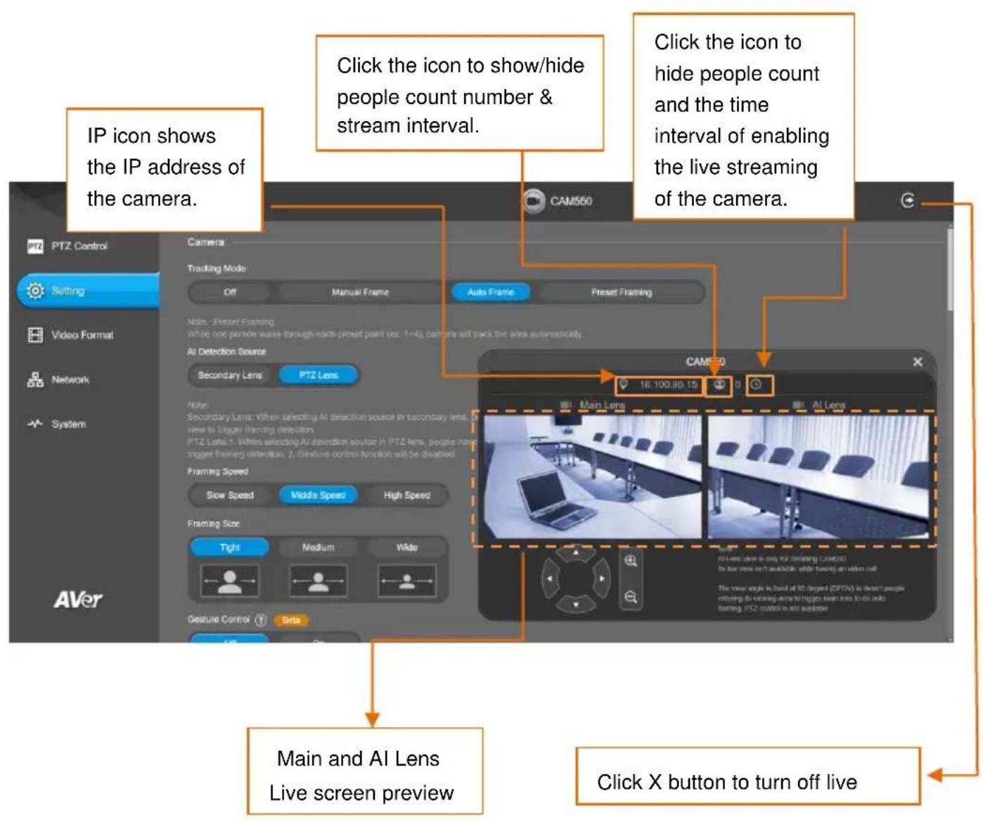
The video icon is to turn on camera live view while adjusting any settings.
Tracking Mode
Select Setting > Camera > Tracking Mode > Off, Manual Frame, Auto Frame, or Preset Framing.

■ Off: Tracking mode is disabled.
■ Manual Frame: User one-click SmartFrame button and camera will adjust view angle to fit all participants in screen.
[Note] While in Auto Framing mode, or doing one-click manual frame, an icon message (be
shown when using HDMI out) will display on the upper left screen to indicate that the framing action is triggered. The icon will appear 2\~3 sec on the screen. Once the framing process is done, it will disappear. If you don't want to see the icon display, please go to PTZApp 2, find "On Screen Menu" function and select "Off".
■ Auto Frame: AI lens (secondary lens) is with 95 degree panoramic view of the room to keep detecting all participants or new participants and trigger PTZ lens to dynamically frame all participants.
*The default framing speed is “Middle” speed. “High” speed is more suitable for one person tracking.
natural_image
Close-up of a black video camera with lens and frame structure (no visible text or symbols)Lens 1: Showing the view after framing all people
Lens 2: Panoramic view of the whole room
Please note that the angle of AI lens is larger than PTZ camera. If people at two sides of meeting room sit within AI lens view but out of PTZ lens' widest angle, they won't be framed and appear in the view of PTZ lens successfully. When this situation happens, please come closer to make sure people at two sides can be within PTZ camera's viewing angle.
[Note] If camera cannot find people while zooming out to wide, it will go Preset 0.
■ Preset Framing: This is designed for requiring a specific zooming area with preferred image proportion. Set up preset points in advance (Only for Preset points 1\~9 and Preset 0 is for home position. The preset points must be within the AI lens angle of view.) Make sure the preset areas are within AI lens' view. When any of people enter a preset area, the PTZ camera will immediately
shoot the preset zones instead of focusing and zooming into presenter. PTZ Camera tracks and frames all the participants if none of them touch any preset area. To keep the screen stable, whenever there is a person in the area, the camera won't move any more until no one shows up. However, the camera can detect the direction where the last person goes. If the person goes to the next preset area with overlap section, the camera will directly move to the next preset area. Thus, to ensure smooth transition, please set up zones with overlapping presets.
If the preset zones do not overlap and when the last person leave the preset area, camera will zoom out to wide to find people and frame them again.
If more than 2 presets areas are touched by 2 persons, camera will go to preset 1. The priority is preset 1>preset2> preset 3....>preset 9
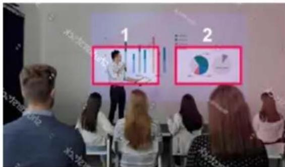
Separate preset area setting
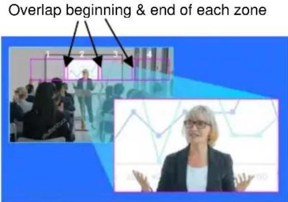
Overlap preset area setting
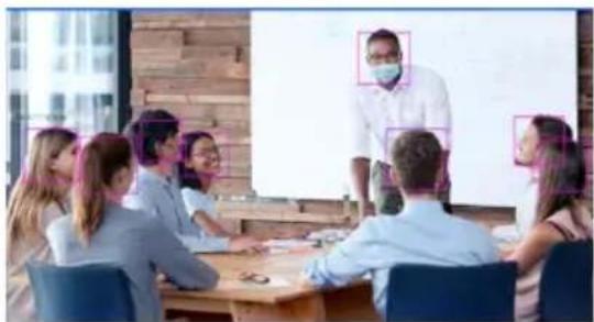
[Note] CAM550 frames people in masks or any facial profile up to 7\~10 meters away!
natural_image
Group of business professionals in a meeting room with a presentation screen (no visible text or symbols)AI Detection Source
Select Setting > Camera > AI Detection Source.
AI Detection Source
Secondary Lens
PTZ Lens
Note:
Secondary Lens: When selecting AI detection source in secondary lens, people have to be within its field of view to trigger framing detection.
PTZ Lens:1. When selecting AI detection source in PTZ lens, people have to be within its field of view to trigger framing detection. 2. Gesture control function will be disabled.
Secondary Lens: When selecting AI detection source in secondary lens, people have to be within its field of view to trigger framing detection.
■ PTZ Lens:
- When selecting AI detection source in PTZ lens, people have to be within its field of view to trigger framing detection.
- Gesture control function will be disabled.
Framing Speed
Select Setting > Camera > Framing Speed > Slow Speed, Middle Speed, or High Speed (default). When in auto framing or preset framing mode, camera will automatically frame people if they stand still without moving for 1\~5 seconds.
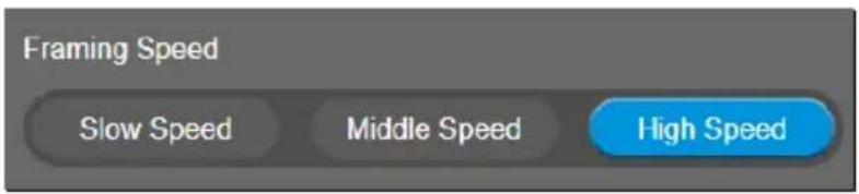
■ Slow Speed: camera starts to frame people if they don't move for 5 seconds.
Middle Speed: camera starts to frame people if they don't move for 3 seconds.
- High Speed: camera starts to frame people if they don't move for 1 second.
[Note] The default framing speed is "Middle" speed. "High" speed is more suitable for one person tracking.
Framing Size
Select Setting > Camera > Framing Size > Tight (default), Medium, or Wide.
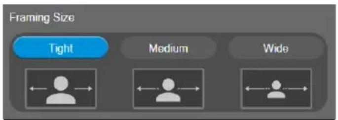
■ Tight: It provides a close-up view of meeting participants.
■ Medium: It provides a medium view of meeting participants.
■ Wide: It provides a wide view of meeting participants.
Gesture Control
Enable gesture control allows user to use hand to control camera for turning on/off tracking function, zooming in/out. Click “?” icon to show gesture control list on screen.
[Note] The effective distance is up to 5-meter away from the camera.
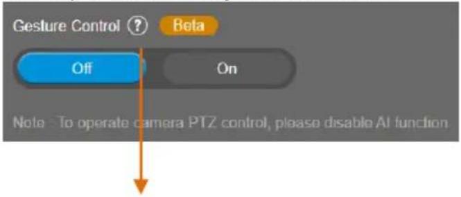
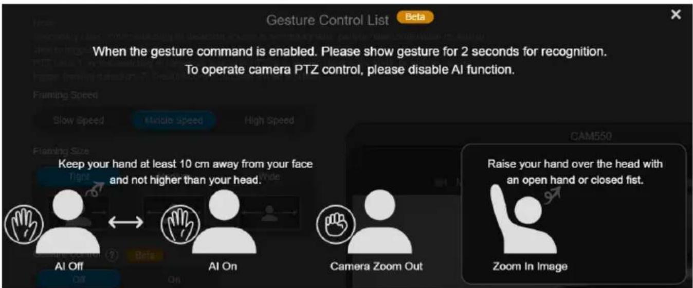
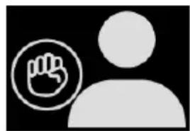
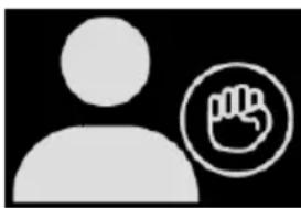
Turn on gesture control function first. When any of the following gestures are showing in front of the camera, it will activate gesture control function. Keep showing the gesture for 2\~3 seconds to trigger the camera to act. The following are the corresponding function names and gesture figures.
| Gesture Control | Description | |
Tracking On/Tracking Off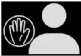 or or 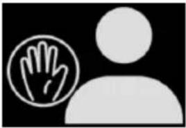 | You have to be in the view of PTZ lens.Raise the palm of your hand to face the camera and place it on the side of your face (not over the head) for 2~3 seconds to activate or disable tracking function. Your hand has to be at least 10cm away from your face.Turn off tracking function before doing zoom in/out function. | |
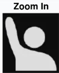
natural_image
Icon showing a hand gesture inside a circle next to a human silhouette (no text or symbols)or
natural_image
Silhouette of a person next to a hand icon (no text or symbols)You have to be within the view of AI lens.
Raise your hand over your head for 2\~3 second to zoom in camera. If there are more than one people raising the hand, the camera will follow the 1st one until he puts down the hand.
Turn off tracking function before doing zoom in/out function.
Zoom Out
You have to be in the view of PTZ lens.
Place a fist with palm facing the camera on the side of the face for 2\~3 seconds to activate the zoom out. Your hand has to be at least 10cm away from your face.
Turn off tracking function before doing zoom in/out function.
Auto Focus
Set auto focus mode.
First select Setting > Camera > Camera Focus > Auto.
Select Setting > Camera > Auto Focus > PTZ or Continuous.

■ PTZ: Click the button (such as pan, tilt, or zoom in/out) to adjust focus once.
■ Continuous: The camera will adjust the focus when the objects have moved.
Camera Focus
Set auto/manual focus mode.
Select Setting > Camera > Camera Focus > Auto or Manual.
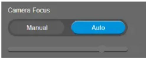
■ Auto: Camera adjusts focus automatically.
■ Manual: You can adjust the camera focus by moving the control bar below.
Home Position
Every time when powering on the camera, it will turn to this position.
Select Setting > Camera > Home Position > Last Operation Position, Factory Center Position, or Preset 0.

Sleep Position
When the camera idles for certain period, it will enter sleep mode and go to the sleep position. Please set up sleep timer to enable sleep mode.
Select Setting > Camera > Sleep Position > Factory Downside Position or Preset 9.

Sleep Timer
Set the camera idle time to enter sleep mode. When entering sleep mode, the camera will turn to sleep position.
Select Setting > Camera > Sleep Timer > Off, 10 sec, 5 min, 10 min, or 20 min.
Please notice that whenever there is USB streaming or RTSP/RTMP streaming, the camera won't enter sleep mode.

On Screen Menu
Enable/disable on screen display status information. For instance, when it is at auto frame mode, it will appear "☐" on the upper left side of the screen. If you don't want to see the icon, please select Off.
Select Setting > Camera > On Screen Menu > Off, On, or Load Preset Off.

Camera Binding
With multiple cameras connection, users can set each camera to buttons 1 to 3 on the remote control.
Select Setting > Camera > Camera Binding > Camera1, Camera2, or Camera3.
[Note] When camera binding is off, press camera 1, 2, or 3 button on the remote control can control all the AVer USB camera nearby you.

Save Preset
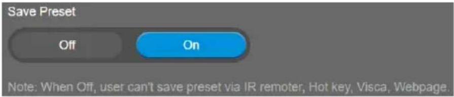
Enable/disable "save preset" function. When applicable, IT personnel can limit end-user access to change preset points by locking "save preset" function and switching this function off.
When off, user can't save preset points via IR remote, Hot key, VISCA, and webpage.
Select Setting > Camera > Save Preset > Off or On.
HDMI Screen Layout
To set HDMI output type – Lens 1, Lens 2, PIP 1, PIP 2, or PIP 3.
When select PIP 1, 2, or 3 layout, user can click

to switch lens 1 and 2 display position.
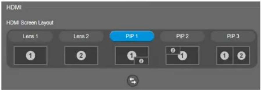
Image Settings
Frequency
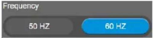
Select the frequency of the camera.
Select Setting > Image > Frequency > 50 HZ or 60 HZ.
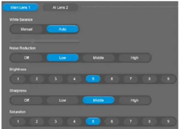
Main Lens 1/AI Lens 2
Select Main Lens 1 or AI Lens 2 to setup lens' parameters – White Balance, Noise Reduction, Brightness, Sharpness, and Saturation. Those settings only apply for selecting lens.
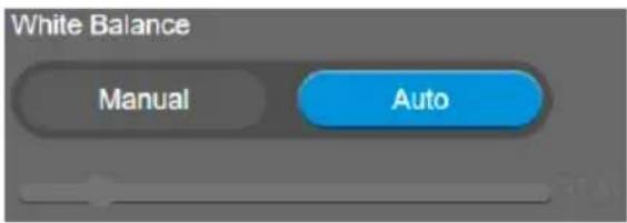
White Balance
Select the white balance setting for various light conditions or color temperature.
Select Setting > Image > White Balance > Auto or Manual.
Noise Reduction
To reduce the noise from the signal.
Select Setting > Image > Noise Reduction > Off, Low, Middle, or High.

Brightness
Adjust the value of brightness.
Select Setting > Image > Brightness > 1 \~ 9.

Sharpness
Adjust the value of sharpness.
Select Setting > Image > Sharpness > Off, Low, Middle, or High.

Saturation
Adjust the value of saturation.
Select Setting > Image > Saturation > 1 \~ 9.

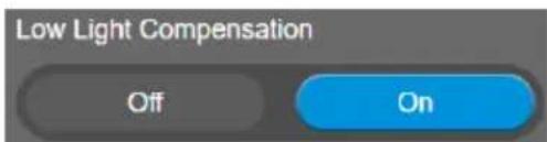
Low Light Compensation
Select Setting > Image > Low Light Compensation > Off or On.
Please notice that the frame rate will drop to 10\~15 fps.
Allow Remote Access
Select Setting > Image > Allow Remote Access > Off or On.
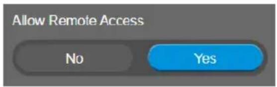
[Note] Only available on PTZApp2
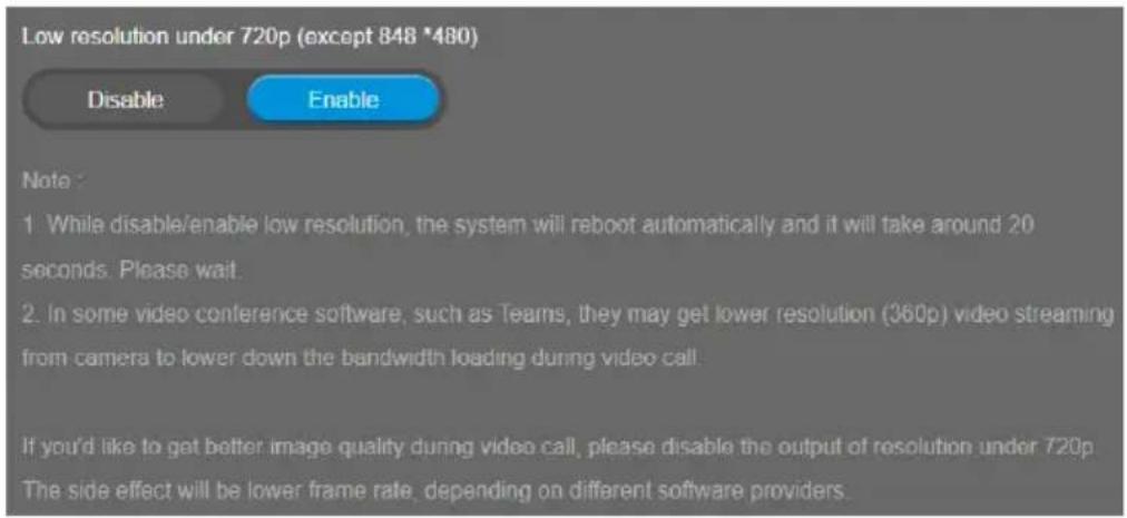
Low resolution under 720p
Select Setting > Image > Low resolution under 720p > Disable or Enable.
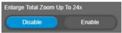
Enlarge Total Zoom Up To 24x
Enable/Disable enlarge zoom up to 24x. The default is 18x.
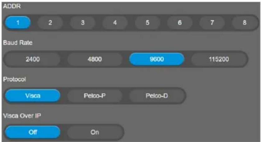
RS232 Settings
When CAM550 connects with PTZ camera controller through the RS232 port, please setup ADDR, Baud Rate, Protocol, and Visca Over IP settings.
Select Setting > RS232.
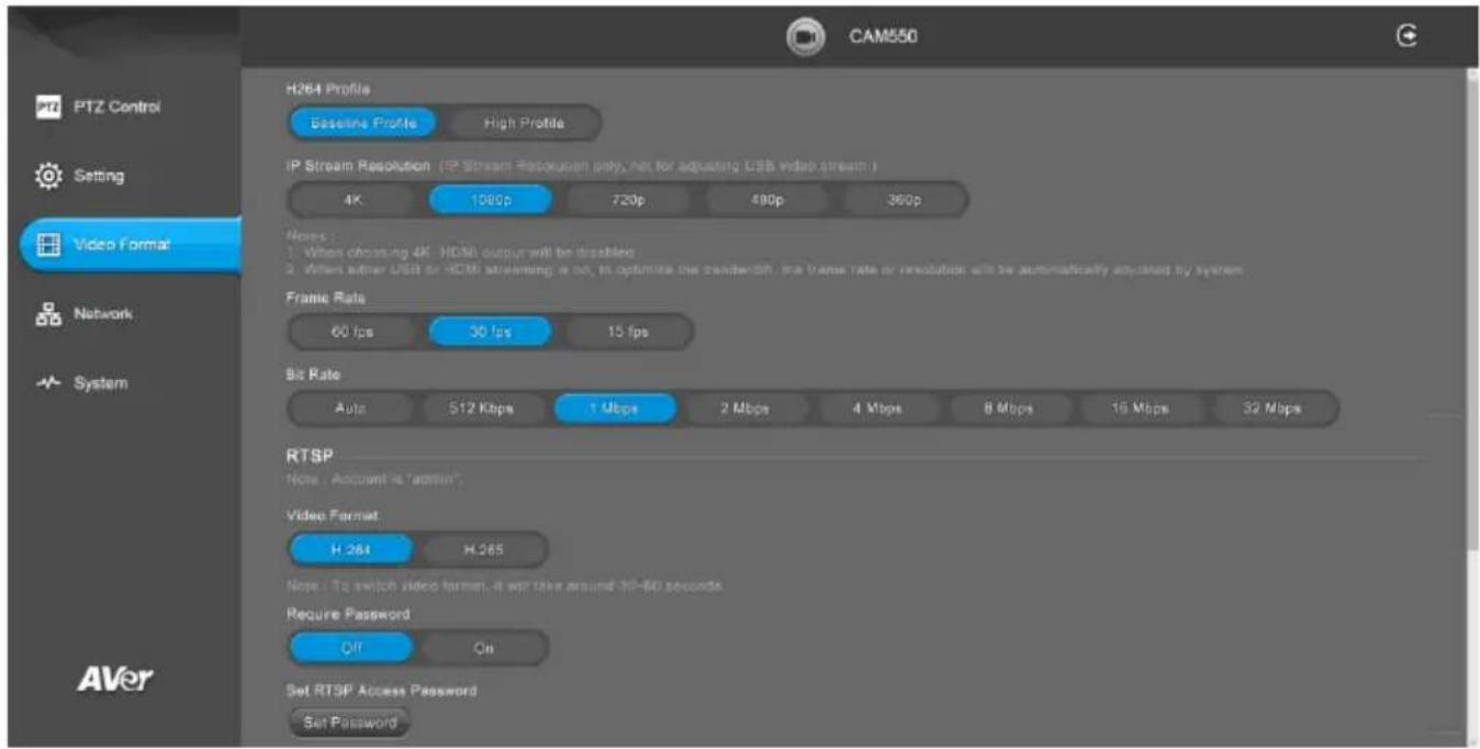
Video Format Settings
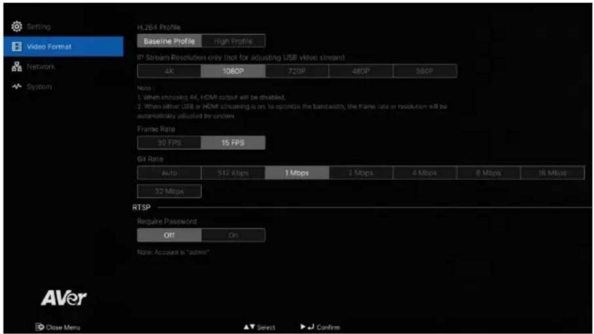
H.264 Profile
While in live broadcasting, user can choose preferable profile to get best streaming quality.
Select Video Format > H.264 Profile > Baseline Profile or High Profile.

IP Stream Resolution only
Set up the resolution for IP stream. Not supported for USB video stream.
Select Video Format > IP Stream Resolution only > 4K, 1080P, 720P, 480P, or 360P.

Please notice that if USB streaming (VC software side) is already in use at 1080p/30fps, the IP streaming resolution (RTSP) will be limited to 720p/30fps.
[Note]
■ When choosing 4K, HDMI output will be disabled.
■ When either USB or HDMI streaming is on, to optimize the bandwidth, the frame rate or resolution will be automatically adjusted by system.
Frame Rate
Set up the frame rate value.
Select Video Format > Frame Rate > 60 FPS, 30 FPS, or 15 FPS.

Bit Rate
Set up the bit rate value.
Select Video Format > Bit Rate > Auto, 512 Kbps, 1 Mbps, 2 Mbps, 4 Mbps, 8 Mbps, 16 Mbps, or 32 Mbps.
For Facebook live broadcasting, it's suggested to choose less than 4Mbps to ensure smooth streaming.

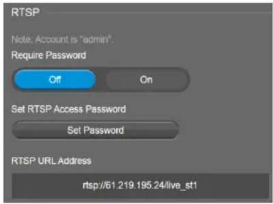
RTSP
To use RTSP player connecting to the camera, please enter the RTSP URL which displays on the web in your application such as VLC, PotPlayer, or Quick Time.
Select On/Off to enable/disable password requirement while opening RTSP.
[Note] Account is "admin"
Set RTSP Access Password
- Select Video Format > RTSP > Set RTSP Access Password.
- Enter the new password.
- Select Change to save the new password.
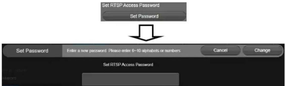
flowchart
graph TD
    A["Set RTSP Access Password"] --> B["Set Password"]
    B --> C["Set Password"]
    C --> D["Enter a new password: Please enter 6~10 alphabels or numbers"]
    D --> E["Cancel"]
    D --> F["Change"]
    G["Set RTSP Access Password"] --> H["End"]
RTMP
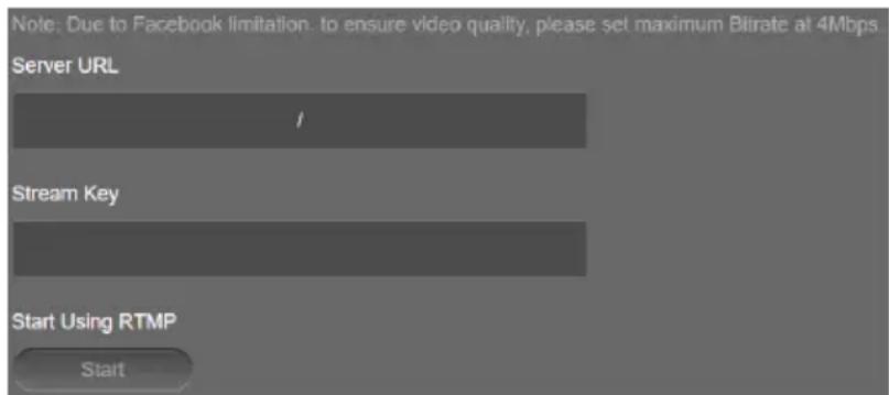
Set up for uploading the camera's live view to the broadcasting platform (e.g. YouTube).
Select Video Format > RTMP.
- Locate the RTMP server URL and stream key from the broadcasting platform and enter in Server URL and Stream Key fields.
- Select Start to begin uploading the live video of the camera to the broadcasting platform.
- Select Stop to stop uploading the video.
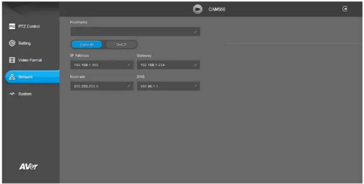
Network Settings
DHCP
Enable DHCP function.
Select Network > DHCP. A message is shown and clicks Continue to confirm.
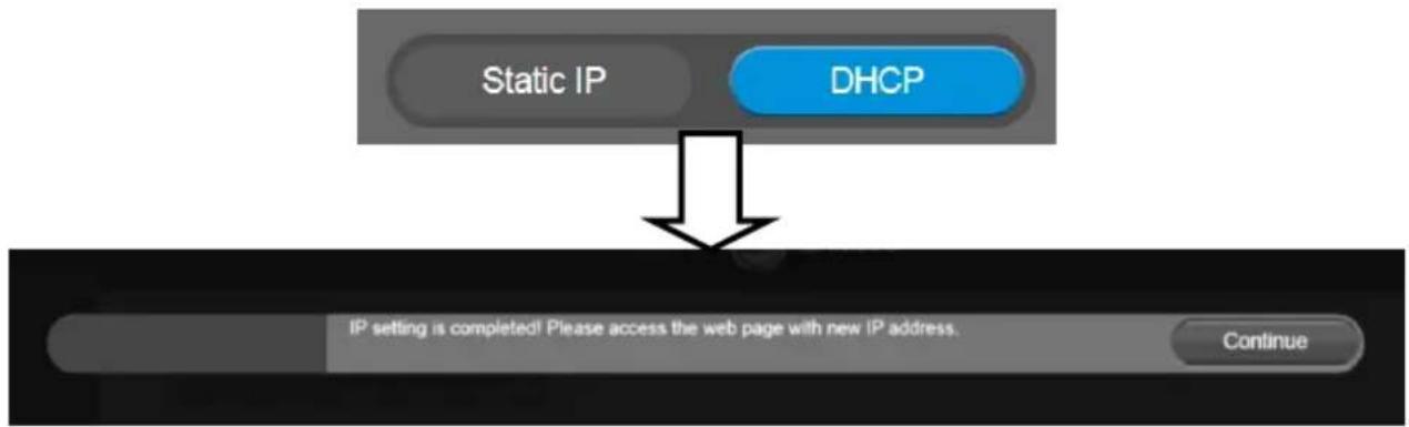
flowchart
graph TD
    A["Static IP"] --> B["DHCP"]
    B --> C["IP setting is completed! Please access the web page with new IP address. Continue"]
Static IP
Assign a fixed IP address to the camera.
- Select Network > Static.
-
Click pencil icon and enter the IP Address, Gateway, NetMask, and DNS in the corresponding fields.
-
Select Confirm to complete the setting.

flowchart
graph TD
    A["IP Address 192.168.1.15"] --> B["Gateway 192.168.1.1"]
    B --> C["NetMask 255.255.255.0"]
    C --> D["DNS 192.168.1.1"]

System Settings
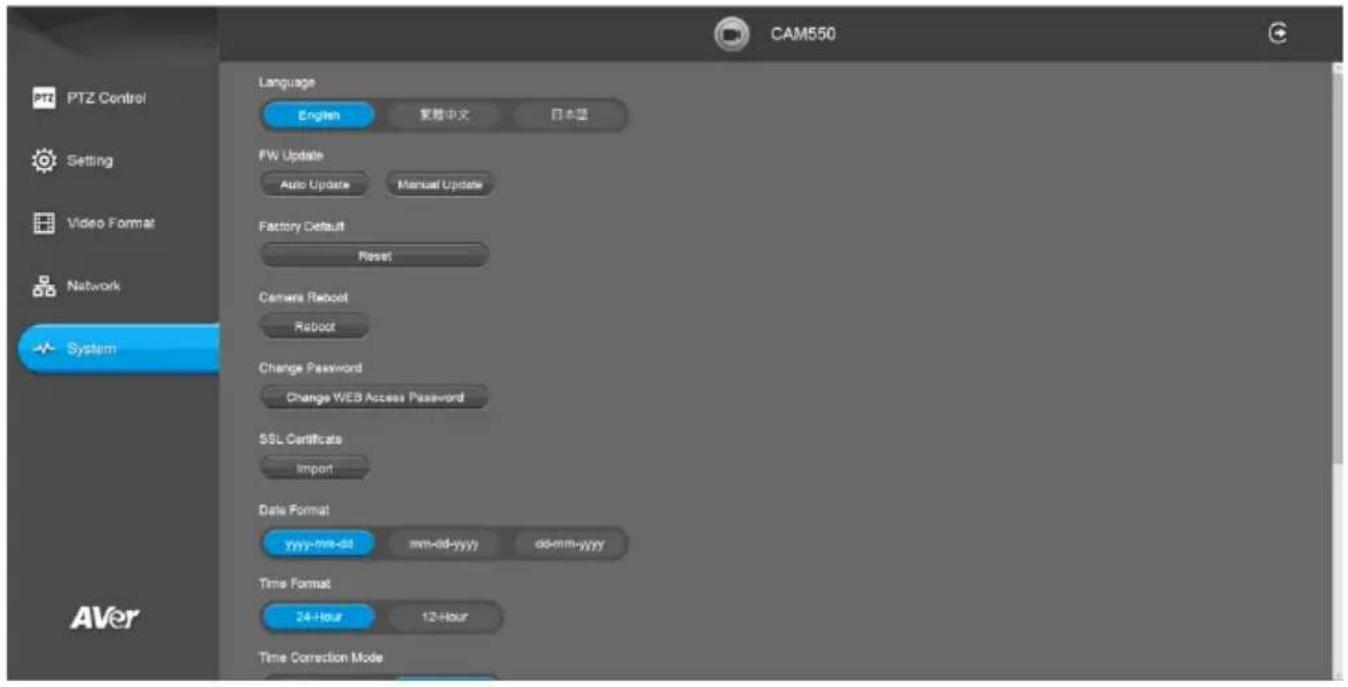
Language
Select the language of the system.
Select System > Language > English, Traditional Chinese, or Japanese.

Update the camera's firmware.
Select System > FW Update > Auto Update or Manual Update.
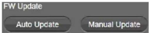
■ Auto Update: The system will check firmware version from AVer server and request to update.
■ Manual Update: To update the firmware from specific location.
After updating, the camera will reboot and the connection will be lost. Please wait for few minutes and always keep the power cable connected. If unplugging the power during this process, it will cause damage of the device.
Factory Default
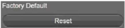
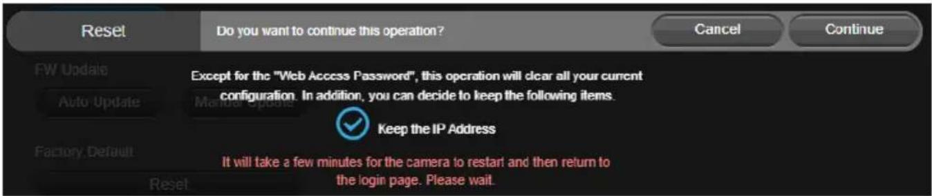
Reset the camera back to factory default setting.
- Select System > Factory Default > Reset.
- User can choose to keep current IP address/Web access password or back to default.
- Select Continue to reset back to factory default.
[Note] When factory default is activated, the password of Webpage login will not be set to default. For security concerns, to reset password of webpage access, please download PTZApp 2 to reset it.

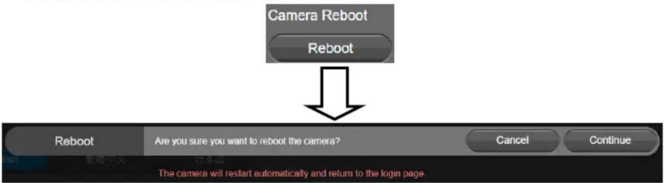
Camera Reboot
Restart the camera manually.
- Select System > Camera Reboot > Reboot.
- Select Continue to reboot the camera.
flowchart
graph TD
    A["Camera Reboot"] --> B["Reboot"]
    B --> C{Are you sure you want to reboot the camera?}
    C -->|Yes| D["Cancel"]
    C -->|No| E["Continue"]
Change Password
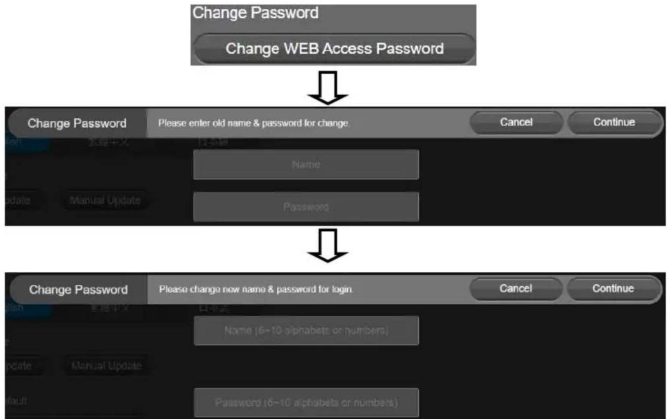
Change the web login password. The default password is "aver4321".
- Select System > Change Password > Change WEB Access Password.
- Enter the old account and password. Select Continue.
- Enter the new account and password. Select Continue to save the new setting.
- If users forget the password and want to revert back to the default password, please use PTZApp 2 to reset it.
flowchart
graph TD
    A["Change Password"] --> B["Change WEB Access Password"]
    B --> C["Change Password"]
    C --> D["Please enter old name & password for change."]
    D --> E["Cancel"]
    D --> F["Continue"]
    G["Change Password"] --> H["Please change new name & password for login."]
    H --> I["Cancel"]
    H --> J["Continue"]
    K["Name"] --> L["Password"]
    M["Manual Update"] --> N["Password"]
    O["Date"] --> P["Password"]
    Q["Date"] --> R["Password"]
    S["Date"] --> T["Password"]
    U["Date"] --> V["Password"]
Trouble Shooting
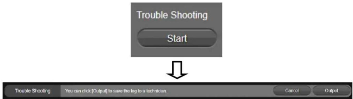
Output log to save in local PC.
- Select System > Trouble Shooting > Start.
- Select Output.
flowchart
graph TD
    A["Trouble Shooting"] --> B["Start"]
    B --> C["You can click [Output"] to save the log to a technician.]
    C --> D["Cancel"]
    C --> E["Output"]
[Note] Only available on PTZApp2
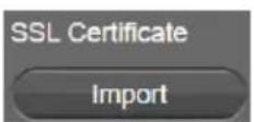
SSL Certificate
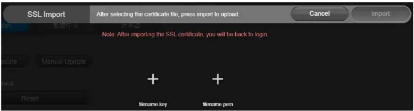
Import the SSL certificate from specific location.
- Select System > SSL Certificate > Import.
- Select the type by clicking "+".
- Direct the file location.
- Select Import.
[Note] If you want to disable SSL certificate function, please use PTZApp 2 to switch off this function.

Date Format
Select the date format.
Select System > Date Format > yyyy-mm-dd, mm-dd-yyyy, or dd-mm-yyyy.

Time Format
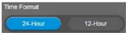
Set up the time format.
Select System > Time Format > 24-Hour or 12-Hour.
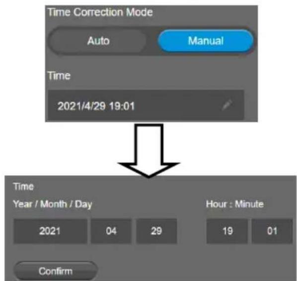
Time Correction Mode
Adjust time automatically or manually.
Select System > Time Correction Mode > Auto or Manual.
■ Auto: The system time will be set by NTP server on the network. Click the pencil icon of NTP Server and enter the URL of NTP server. Select the Time Zone. Select NTP Update to save setting. Select Confirm to start auto time adjustment.
[Note] Our default NTP server is located in the USA. If this does not work in your country, please manually key in the desired NTP server.
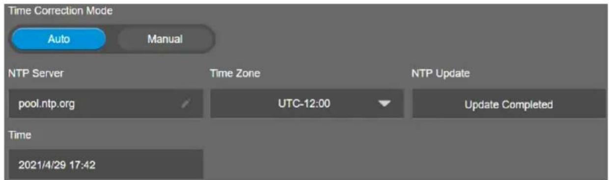


■ Manual: User can set up time manually. Click the pencil icon and enter the Year, Month, Day, Hour, and Minute. Select Confirm to save the settings.
flowchart
graph TD
    A["Time Correction Mode"] --> B["Auto"]
    A --> C["Manual"]
    B --> D["Time"]
    C --> D
    D --> E["2021/4/29 19:01"]
    F["Time"] --> G["Year / Month / Day"]
    F --> H["Hour : Minute"]
    I["Confirm"] --> J["2021"]
    I --> K["04"]
    I --> L["29"]
    I --> M["19"]
    I --> N["01"]
Information
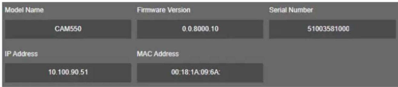
Display the information of Model Name, Firmware Version, Serial Number, IP Address, and MAC Address.
Select System > Information.
In PTZApp 2, user can change the IP address setting of CAM550, configure the parameters of the camera, set up AI tracking functions and some advanced image settings, pan, tilt, and zoom the camera.
Install PTZApp 2
Please go to https://www.aver.com/download-center (Global & European Headquarters) or https://www.averusa.com/business/support/ (USA) to download the PTZApp 2. After downloading, double-click on the file and follow the on-screen instructions to complete the installation. After installing the PTZApp 2, double-click on the PTZApp 2 icon to run the application.
Use PTZApp 2 with USB Devices
- Run your video application and make a video call.
- During your video call, you can use the PTZApp 2 to pan, tilt and zoom the camera in/out and enable/disable the true WDR, brightness, and sharpness feature.
- Launch PTZApp 2 ( ) and it will open in Chrome browser automatically.
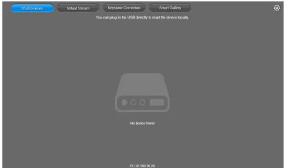
- Choose "USB device" and connect CAM550 to PC/laptop with USB cable. When the camera is detected, the product card will show up.
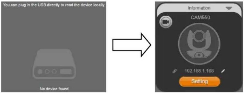
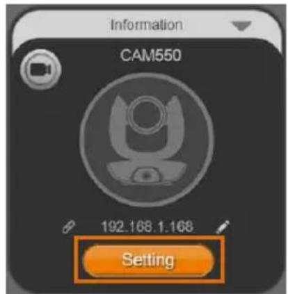
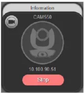
- Set up IP address. The camera default IP address is 192.168.1.168. Click pencil icon (☐) to edit IP address.
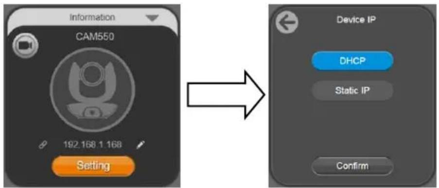
flowchart
graph LR
    A["Information CAM550"] --> B["Setting"]
    B --> C["Device IP"]
    C --> D["DHCP"]
    C --> E["Static IP"]
    C --> F["Confirm"]
- Click the setting icon to change Language, Hotkey Control, and PTZApp 2 Version.
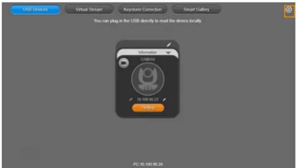
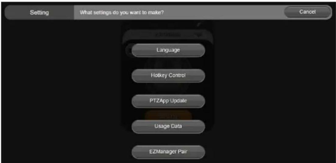
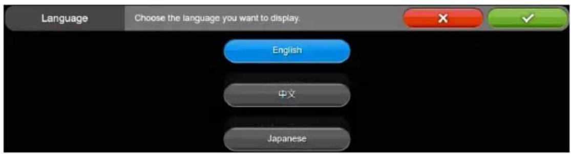
■ Language: Select desired language and click the check icon to confirm the selection.
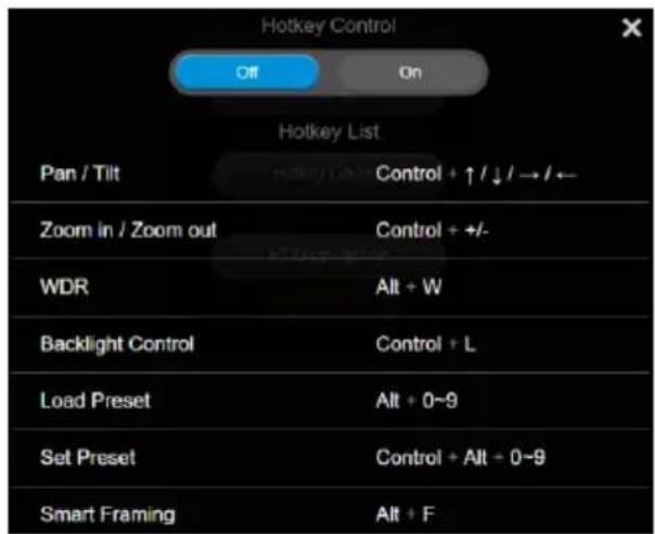
■ Hotkey Control: User can control the camera by using keyboard. This is a general list for all AVer USB Cameras. Backlight control equals to WDR function in CAM550.
■ PTZApp Update: Get current PTZApp 2's version number and do auto update here.

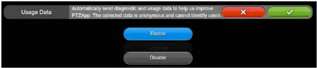
■ Usage Data: Should you click the check mark, PTZApp2 will automatically send us the diagnostic and usage data to help us improve PTZApp2. The collected data is anonymous and cannot identify users.
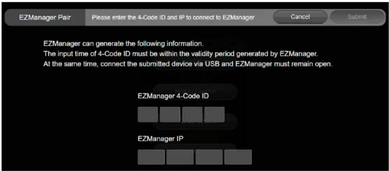
■ EZManager Pair: Enter THE 4-Code ID and IP to connect to EZManager.
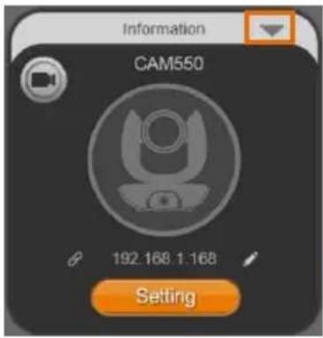
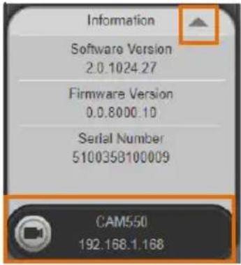
- Information: Click the drop-down triangle icon to review the information of camera. To minimize the information, click the triangle or the bottom area of the information icon.
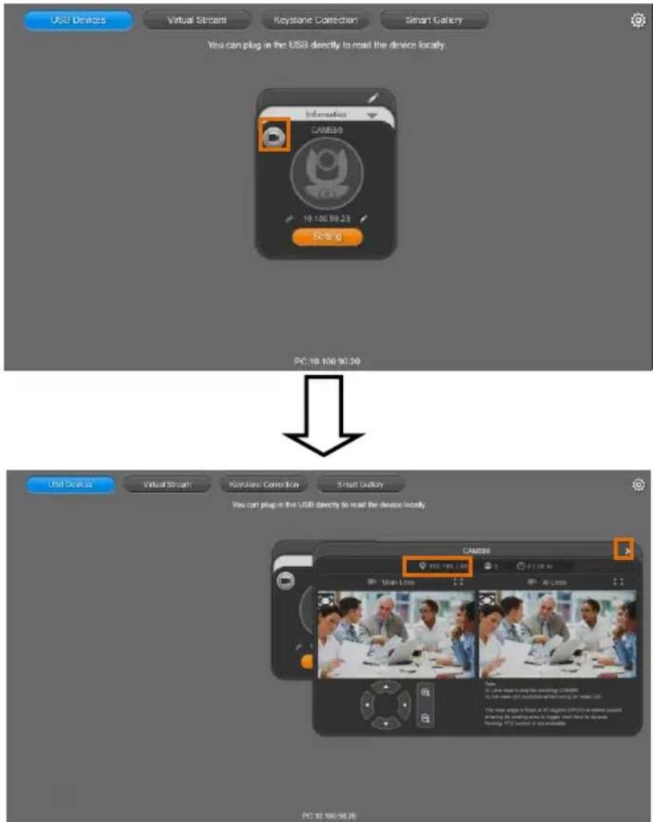
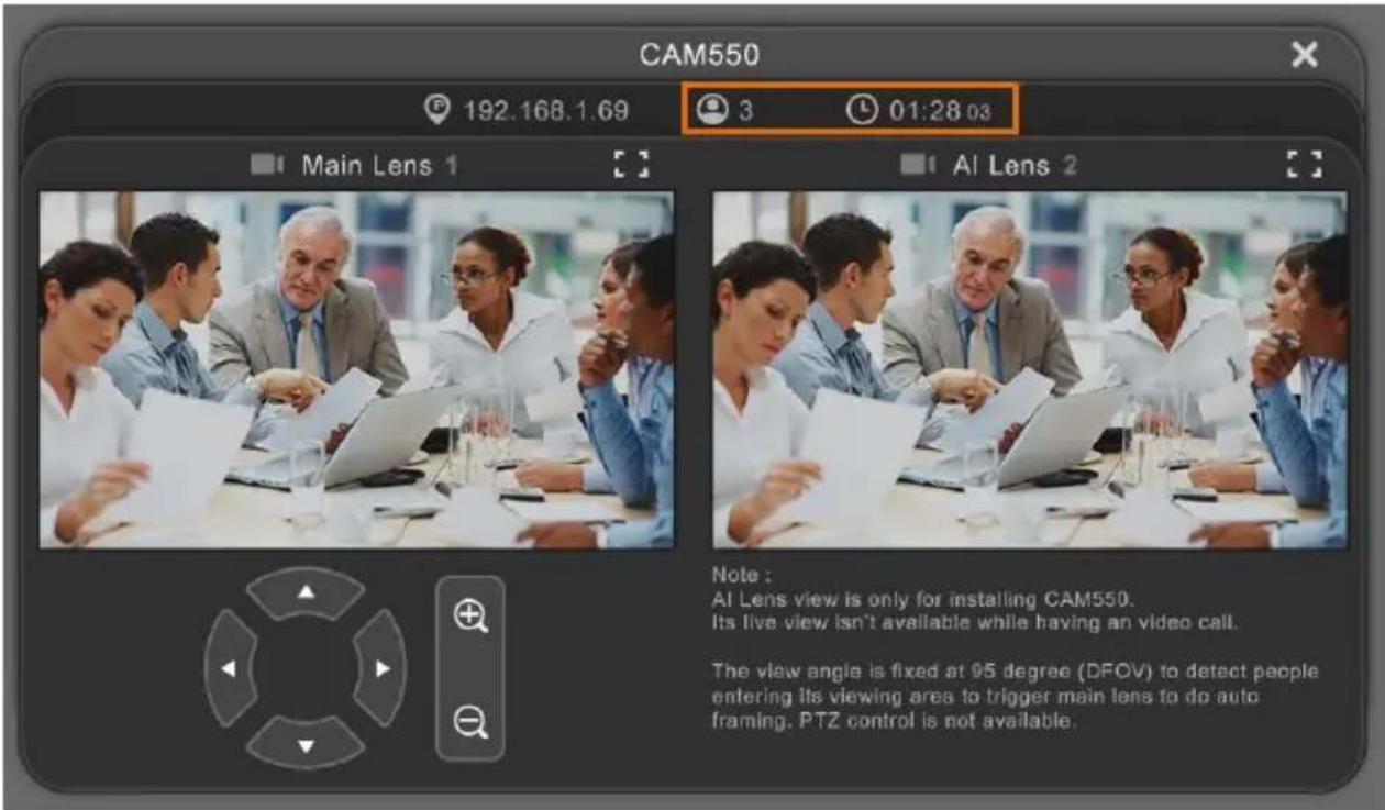
- Camera: Click the camera icon to view the camera live view. IP address is displayed as well. Click the X icon to close the camera live view. If the live video did not appear, please check the camera and the laptop/PC connection to make sure all are correct and well connected.
The resolution of this small live view is 640x480 resolutions.
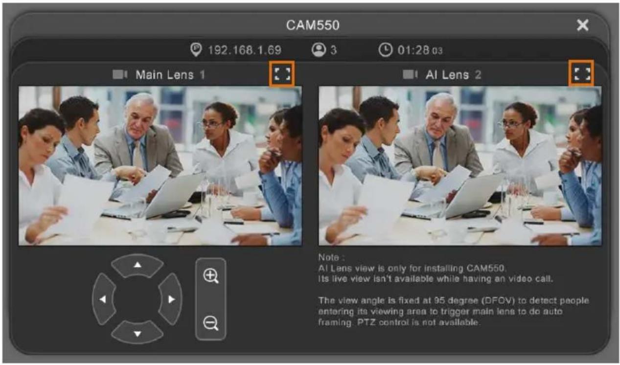
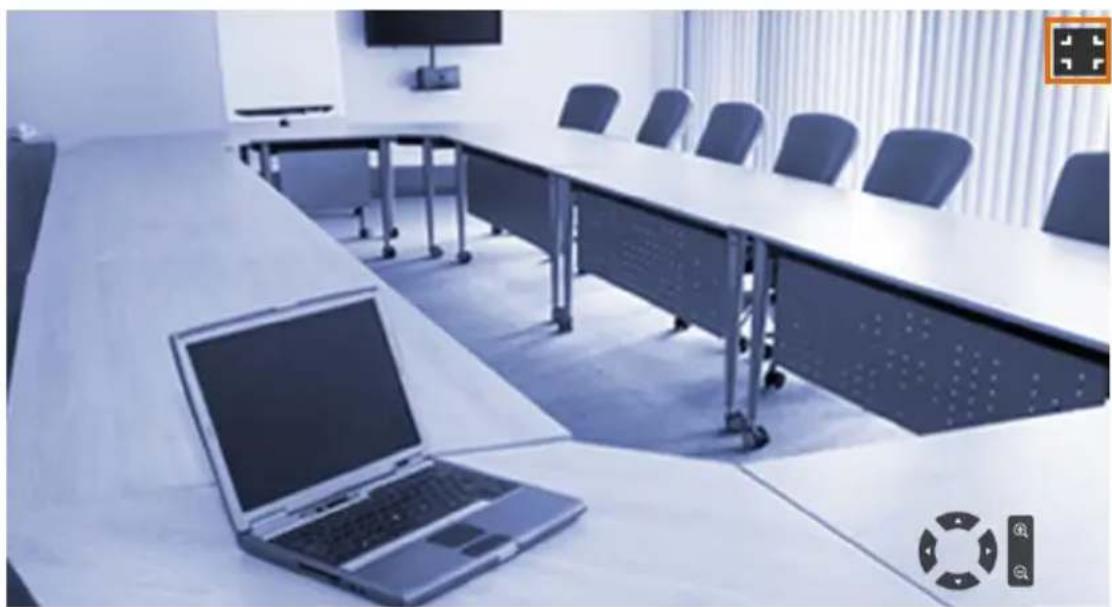
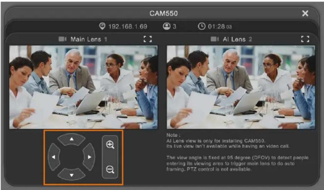
Full Screen: PTZApp 2 can switch to full screen mode. Click “” icon and video screen
will switch to full screen mode. In full screen mode, user can use direction panel to control camera

direction. Click "icon to go back to normal screen view.
The resolution of full screen mode is 1080p/30fps.

natural_image
Interior view of a modern conference room with large U-shaped tables, chairs, and a laptop on a table (no visible text or symbols)People Count and Stream Interval: Click the 📷 icon to show people count number and stream interval. Click the 📷 or 📸 icon to hide the stream interval.
➢ Control Panel: To control the camera direction, zoom in and out during your video call.
- Setting: Click "Setting" button to set up parameters of the camera and speakerphone. Click arrow icon to leave the Setting page.

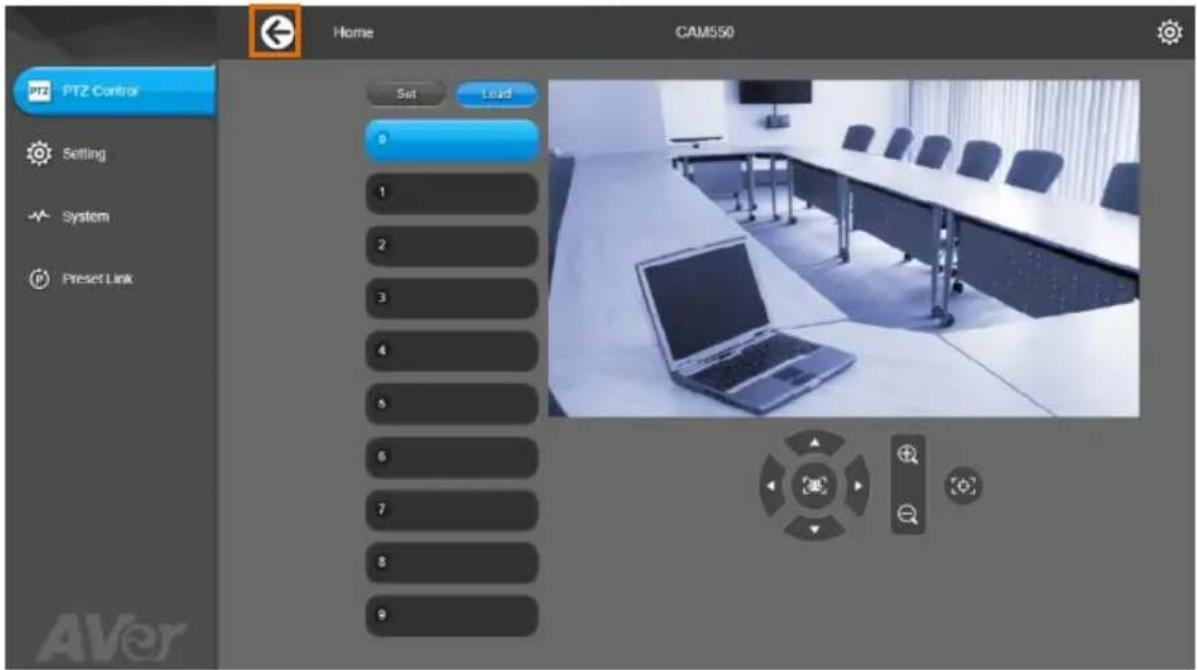
PTZ Control: Use control panel to set up preset positions. Since most of operations are the same as web page, refer to Set Up the Preset section (pages 39) for detailed setup.
Setting: To set up parameters of the camera. Since most of operations are the same as web page, refer to Camera Settings, Image Settings, and RS232 Settings section (pages 41\~51) for detailed setup.
[Note] To set up RS232 parameters, please select "Off" for SSL Function on IP Web Page setting.
System: To set up system. Since most of operations are the same as web page, refer to System Settings section (page 57) for detailed setup.
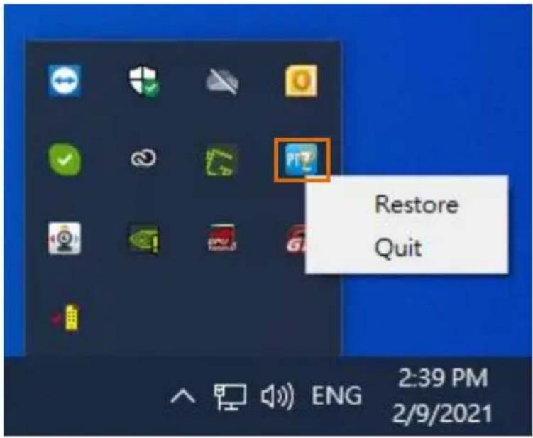
- PTZApp 2 Quit & Restore: To quit the application, right-click the icon on the system tray and select "Quit". If you can't launch PTZApp 2 right after installation, please right –click the icon and choose "Restore".
Use PTZApp 2 with a Virtual Stream
With this function, you can have a virtual meeting with only Ethernet connection and get rid of USB cable connection. Make sure the camera is connected with Ethernet and under the same subnetwork as the meeting room PC (e.g. NUC).
[Note]
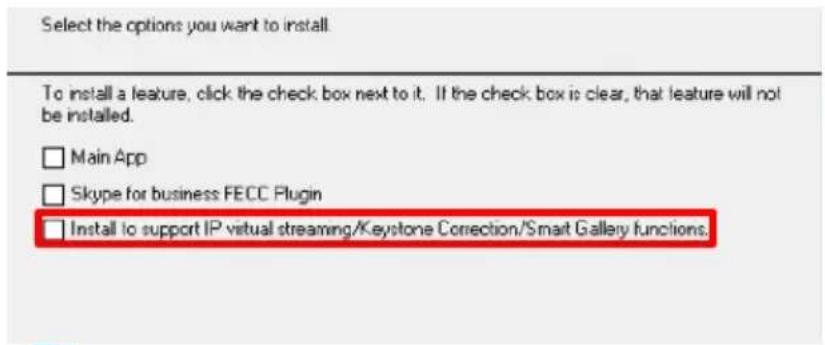
While installing PTZApp2, if you refuse to install IP virtual streaming, Keystone Correction and Smart Gallery plug-in on your Windows PC (as photo below), you will not use Virtual Streaming function. If you would like to enable this function, please reinstall PTZApp2.
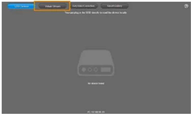
- Launch PTZApp 2 (PTZ) on a PC and click Virtual Stream.
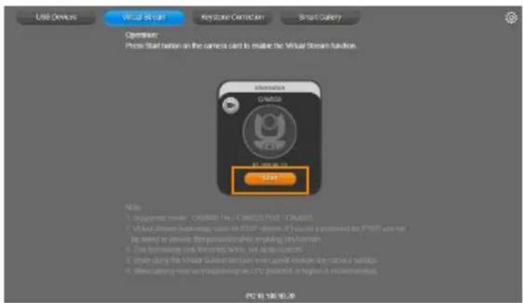
- When the camera card appears, click Start to enable the Virtual Stream function.
- Virtual Stream technology uses an RTSP stream. If you set a password for RTSP, you will be asked to provide that password while enabling this function.
![AVer VC550 - [Note] - 4](/content/2026/05/905106/images/10d1814a0c82e98abdd7279a4bf81b046220ee3708933c312a50b177acea47d0.jpg)
- Launch VC software (e.g. Zoom, Teams, Skype) and choose AVer USB VCam as the video source to start collaborating.
- While using the Virtual Stream function, you cannot change any camera settings. To pan/tilt or zoom in/out the camera, use a remote control or VISCA control.
- Click Stop and Home to stop using this function.
[Notes]
- This technology only transmits video, not audio sources.
- Video latency may vary depending on CPU power (i5 or higher is recommended).
Please go to http://www.aver.com/download-center to download the AVer EZLive software. After downloading, double-click on the file and follow the on-screen instructions to complete the installation.
Use AVer EZLive
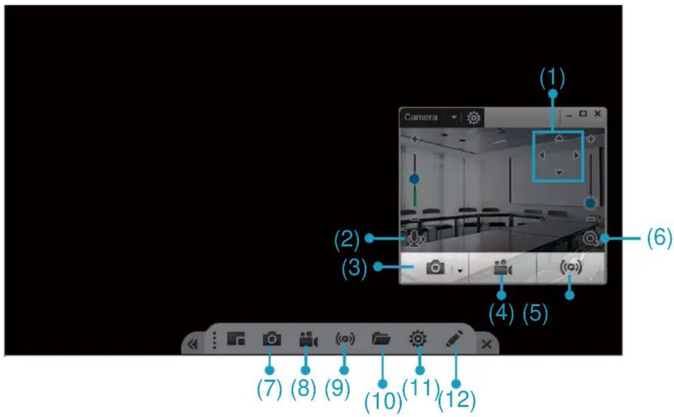
During a video call, EZLive can help user to do:
(1) Camera ePTZ
(2) Volume control for the speaker connected
(3) Capture camera's still images
(4) Record video
(5) Live stream to Youtube, Livehouse.in, USTREAM...etc.
(6) Camera Zoom in/out
(7) Capture PC screen shot
(8) Record PC screen video
(9) Set up livestream
(10) Open file management to retrieve photos and video files
(11) Livestream setting
(12) Drawing tool
- VC550
- User Manual
- Federal Communications Commission Statement
- Warning:
- TRADEMARKS
- COPYRIGHT
- NOTICE
- WARNING
- Remote Control Battery Safety Information
- CAUTION
- 遥控器电池安全信息
- Headquarters
- USA Branch office
- Europe Branch office
- Contact Information
- Japan Branch Office
- Vietnam Branch Office
- Operating the Camera....33
- Package Contents
- Optional Accessories
- Overview
- Camera LED Indicator
- Gesture control
- Speakerphone
- Speakerphone button
- Speakerphone LED Indicator
- Installation Camera
- [Notes]
- Connect the camera to the computer/laptop.
- [Note]
- Remote Control
- Name
- Function
- Device Connection
- Power Connection
- Wall outlet
- PoE
- HDMI Connection
- RS232 Connection
- ■ Camera RS232 Port Pin Definition
- Computer/Keyboard Controller and Camera Connection
- Direct Connection
- ■ Camera Cascade Connection
- Wall Mount Installation
- Screw
- Ceiling Mount Installation (Optional)
- Dimension
- To mount the camera to the ceiling:
- To mount the camera to the calcium silicate ceiling:
- Secure the Cables
- Make a Video Call
- Make a Connection through the Browser
- Web Settings
- First Time Login
- Live Screen Operation
- Set Up the Preset
- User can set 10 preset positions.
- Camera Settings
- Tracking Mode
- AI Detection Source
- Secondary Lens
- PTZ Lens
- Note:
- ■ PTZ Lens:
- Framing Speed
- Framing Size
- Auto Focus
- Camera Focus
- Home Position
- Sleep Position
- Sleep Timer
- On Screen Menu
- Camera Binding
- Save Preset
- HDMI Screen Layout
- Image Settings
- Frequency
- Main Lens 1/AI Lens 2
- White Balance
- Noise Reduction
- Brightness
- Sharpness
- Saturation
- Low Light Compensation
- Allow Remote Access
- Low resolution under 720p
- Enlarge Total Zoom Up To 24x
- RS232 Settings
- Video Format Settings
- H.264 Profile
- IP Stream Resolution only
- Frame Rate
- Bit Rate
- RTSP
- Set RTSP Access Password
- RTMP
- Network Settings
- DHCP
- Static IP
- System Settings
- Language
- Factory Default
- Camera Reboot
- Change Password
- Trouble Shooting
- SSL Certificate
- Date Format
- Time Format
- Time Correction Mode
- Information
- Install PTZApp 2
- Use PTZApp 2 with USB Devices
- Use PTZApp 2 with a Virtual Stream
- Use AVer EZLive
Brand : AVer
Model : VC550
Category : Video Conferencing System