
F1DN204KVM-UN-4 - Switch BELKIN - Free user manual and instructions
Find the device manual for free F1DN204KVM-UN-4 BELKIN in PDF.


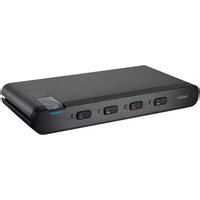
| Product Type | Universal Secure 4-Port Dual-Head KVM Switch with CAC |
| Model | F1DN204KVM-UN-4 |
| Dimensions (W x H x L) | 12.5 x 2.5 x 6.2 inches (317.5 x 63.5 x 157.5 mm) |
| Weight | 4.85 lbs (2.2 kg) |
| Power Requirements | 12V DC, 2.5A (center-pin-positive) with AC adapter (100-240VAC) |
| Number of Users Supported | 1 |
| Number of Computers Supported | 4 |
| Number of Monitors per Computer | 2 (Dual-Head) |
| Video Interface | DisplayPort 1.2 / HDMI 2.0 combo ports |
| Maximum Resolution | 3840 x 2160 @ 60Hz (UHD 4K) |
| Console Ports | 1x DP/HDMI (2x for dual-head), 2x USB-A (keyboard & mouse), 1x USB-A (CAC), 1x 3.5mm audio out |
| Computer Ports | 4x USB-B (KM), 4x USB-B (CAC), 4x DP/HDMI, 4x 3.5mm audio in |
| Channel Selection | Front-panel push buttons (4) |
| LED Indicators | Channel select, Num Lock, Caps Lock, Scroll Lock, CAC/DPP status, audio freeze, video diagnostic |
| Security Features | NIAP Protection Profile PSD v4.0, active anti-tamper system, isolated power domains, unidirectional data diodes (USB/audio/video), EDID emulation, non-reprogrammable firmware |
| Tamper Evident Labels | Holographic seals; any disruption indicates possible tampering |
| Operating Temperature | 32° to 104°F (0° to 40°C) |
| Storage Temperature | -4° to 140°F (-20° to 60°C) |
| Humidity | 0-80% RH, non-condensing |
| Enclosure Material | Heavy-duty extruded aluminum with metal faceplate |
| Mounting | Integrated mounting rails (under-desk or side-wall) |
| Warranty | 3 years (limited); extended available |
| Product Lifecycle | 5 years |
| Country of Origin | Designed in California, assembled in USA |
| Compliance | Common Criteria validated to NIAP PP PSD v4.0 |
Frequently Asked Questions - F1DN204KVM-UN-4 BELKIN
User questions about F1DN204KVM-UN-4 BELKIN
0 question about this device. Answer the ones you know or ask your own.
Ask a new question about this device
Download the instructions for your Switch in PDF format for free! Find your manual F1DN204KVM-UN-4 - BELKIN and take your electronic device back in hand. On this page are published all the documents necessary for the use of your device. F1DN204KVM-UN-4 by BELKIN.
USER MANUAL F1DN204KVM-UN-4 BELKIN
This Belkin product is compliant with the latest NIAP Protection Profile PSD v4.0, which exceeds Protection Profile PSS v3.0.

natural_image
Black Belkin device front panel with four colored ports (green, red, yellow, blue) and a small indicator light on the right side (no readable text or symbols beyond branding)User Manual
F1DN102KVM-UNN4 - Universal Secure 2-Port KVM, PP 4.0
F1DN102KVM-UN-4 - Universal Secure 2-Port KVM with CAC, PP 4.0
F1DN104KVM-UNN4 - Universal Secure 4-Port KVM, PP 4.0
F1DN104KVM-UN-4 - Universal Secure 4-Port KVM with CAC, PP 4.0
F1DN202KVM-UNN4 - Universal Secure 2-Port Dual-Head KVM, PP 4.0
F1DN202KVM-UN-4 - Universal Secure 2-Port Dual-Head KVM with CAC, PP 4.0
F1DN204KVM-UNN4 - Universal Secure 4-Port Dual-Head KVM, PP 4.0
F1DN204KVM-UN-4 - Universal Secure 4-Port Dual-Head KVM with CAC, PP 4.0
Document Number - LNKPG-00674 Rev. B00
TABLE OF CONTENTS
Table of Contents
SECTIONS
1234567
Introduction....1
Package Contents 1
Safety Precautions....2
User Guidance & Precautions 3
Overview 4
Security Features....4
Tamper Evident Labels 5
Other Features 6
Equipment Requirements....8
System Requirements....9
Unit Display Diagrams....10
Specifications....15
Installation....17
Pre-Configuration 17
Connection and Installation....18
Color Coding the Channel Buttons 20
Operating the KVM Switch ....21
Common access Card (CaC) Configuration and Operation....22
Troubleshooting 23
Information....27
INTRODUCTION
Table of Contents
SECTIONS
12345671
Thank you for purchasing this Belkin Secure DisplayPort/HDMI KVM. This Switch is designed for use in secure environment installations. The Switch offers safe centralized control, which prevents unintended data transfer between computers running at different security levels. The Switch provides the highest security safeguards and features that meet today's Information Assurance (IA) computing requirements.
Belkin Universal Secure DisplayPort/HDMI KVM is especially challenging in terms of security as DisplayPort is a very robust protocol by nature, which is capable of transferring various types of information, such as USB and Ethernet other than display. Belkin has developed this unique Secure KVM switch with the highest possible security in mind, assuring no leakage of information between connected computers through any channels including DP dedicated channels.
This User Manual provides all the details you'll need to install and operate your new Switch, in addition to expert troubleshooting advice—in the unlikely event of a problem.
Please note: Belkin Secure KVMs cannot be upgraded, serviced or fixed.
Package Contents
Belkin Advanced Secure DisplayPort/HDMI KVM
12V 2.5A DC Power Supply with WW interchangeable mains connectors
QIG (Quick Installation Guide)
Important: This product is equipped with an always-on active anti-tamper system. Any attempt to open the enclosure may activate the anti-tamper system and render the unit permanently inoperable. If the unit's enclosure appears disrupted or if all the port LEDs flash continuously, please call Belkin Technical Support toll-free at (800) 282-2355.
Revision
A - Initial Release, TBD-2022
Reporting Belkin Product Security Vulnerability
If you are aware of potential security vulnerability while installing or operating this product, we encourage you to contact us immediately at the following email address: gov_security@belkin.com
Table of Contents
SECTIONS
12345671
Safety Precautions
Please read the following safety precautions carefully before using the product:
Before cleaning, disconnect the product from any electrical power supply.
Do not expose the product to excessive humidity or moisture.
Do not store or use for extensive period of time in extreme thermal conditions – it may shorten product lifetime.
Install the product only on a clean secure surface.
If the product is not used for a long period of time, disconnect it from electrical power.
If any of the following situations occurs, have the product checked by a qualified service technician:
Liquid penetrates the product's case.
The product is exposed to excessive moisture, water or any other liquid.
The product is not working well even after carefully following the instructions in this user's manual.
The product has been dropped or is physically damaged.
The product shows obvious signs of breakage or loose internal parts.
In case of external power supply – If power supply overheats, is broken or damaged, or has a damaged cable.
The product should be stored and used only in temperature and humidity-controlled environments as defined in the product's environmental specifications.
Never attempt to open the product enclosure. Any attempt to open the enclosure will permanently damage the product.
The product contains a non-replaceable internal battery. Never attempt to replace the battery or open the enclosure.
This product is equipped with an always-on active anti-tampering system. Any attempt to open the product enclosure will activate the anti-tamper triggers and render the unit inoperable and warranty void.
Table of Contents
SECTIONS
12345671
User Guidance & Precautions
Please read the following User Guidance & Precautions carefully before using the product:
- By default, after product power-up, the active channel is #1.
-
The appropriate usage of peripherals (e.g., keyboard, mouse, display, authentication device) is described in detail in this User Manual's appropriate sections. Do not connect any authentication device with an external power source to product.
-
For security reasons products do not support wireless keyboards and mice. In any case do not connect wireless keyboard/mouse to product.
-
For security reasons products do not support microphone/line-in audio input. In any case do not connect a microphone to product audio output port, including headsets.
-
Product is equipped with an always-on active anti-tampering system. Any attempt to open product enclosure will activate the anti-tamper system indicated by all channel-select LEDs flashing continuously. In this case, product will be inoperable and warranty void. If product enclosure appears disrupted or if all channel-select LEDs flash continuously, please remove product from service immediately and contact technical support.
-
Connecting external USB devices to product CAC port (if equipped):
a. When connecting a USB device that is not qualified or rejected for security reasons to product's CAC port, the CAC LED will flash green and USB device will be inoperable.
b. When connecting a USB device that is undetectable for any reason (e.g. failed device, non-standard device etc.) to product's CAC port, the CAC LED will not illuminate at all and device will be inoperable.
- Do not connect product to computing devices:
a. That include telecommunication equipment;
b. That include frame grabber video cards;
c. That include special audio processing cards.
-
Product has a remote control port in the back panel labeled "Remote"
-
Important! Before re-allocating computers to channels, it is mandatory to power cycle product, keeping it powered OFF for more than 1 minute -
-
Product log access and administrator configuration options are described in product Administrator Guide.
-
If you are aware of any potential security vulnerability while installing or operating product, please remove product from service immediately and contact us in one of the ways listed in this manual.
OVERVIEW
Table of Contents
SECTIONS
1234567
Security Features
The product is designed, manufactured and delivered in security-controlled environments. Below is a summary of the main advanced features incorporated in product:
Advanced isolation between computers and shared peripherals
The emulations of keyboard, mouse and display EDID, prevent direct contact between computers and shared peripherals. Product design achieves maximal security by keeping the video path separate with keyboard and mouse switched together, purging the keyboard buffer when switching channels. All these features contribute to strong isolation between computer interfaces, maintained even when product is powered off.
Unidirectional data flow: USB, audio and video
Unique hardware architecture components prevent unauthorized data flow, including:
Optical unidirectional data flow diodes in the USB data path that filtrate and reject unqualified USB devices;
Secure analog audio diodes that prevent audio eavesdropping with no support for microphone or any other audio-input device;
Video path is kept separate from all other traffic, enforcing unidirectional native video flow. EDID emulation is done at power up and blocks all EDID/MCCS writes. For DisplayPort video, filtration of AUX channel exists to reject unauthorized transactions.
Isolation of power domains
Complete isolation of power domains prevents signaling attacks.
Secure administrator access & log functions
The product incorporates secure administrator access and log functions to provide auditable trail for all product security events, including battery backup life for anti-tampering and log functions. Non-reprogrammable firmware prevents the ability to tamper with product logic. Configuration of front panel LEDs and CAC (if equipped) are covered in the PP4.0 Admin manual.
Always-on, active anti-tamper system
Active anti-tampering system prevents malicious insertion of hardware implant such as wireless key-logger inside product enclosure. Any anti-tampering attempt causes isolation of all computers and peripheral devices rendering product inoperable and showing clear indications of a tampering event to the user.
Holographic security tamper-evident labels are placed on the enclosure to provide a clear visual indication if product has been opened or compromised.
Metal enclosure is designed to resist mechanical tampering with all microcontrollers protected against firmware-read, modification and rewrite.
OVERVIEW
Table of Contents
SECTIONS
1234567
Tamper Evident Labels
Belkin Secure Switch uses holographic tamper evident labels to provide visual indications in case of enclosure intrusion attempt. If for any reason the tamper evident seal is missing, appears disrupted, or looks different than the example shown here, please avoid using the product and call Belkin Technical Support at: (800) 282-2355.
Active Anti-Tampering System
Belkin Secure Switch is equipped with an always-on active anti-tampering system. If mechanical intrusion is detected by this system, the Switch will be permanently disabled and LED will blink continuously.
If product indication tampered state (all LEDs blinking) - please call Technical Support and avoid using that product
Product Enclosure Warning Label
Belkin Secure Switch has the following warning printed next to the location of the product Asset Tag and Tamper Evident labels on product enclosure:

WARNING: This enclosure is tamper proof. The unit will self destruct if opened.
Tamper Evident Label Do not use if disturbed.
OVERVIEW
Table of Contents
SECTIONS
1234567
Other Features
The Belkin Universal Secure DisplayPort/HDMI KVM was designed with the user in mind for today's IT environment. Below is a summary of some features incorporated into the Switch.
Protected Display Information
Protected DDC/EDID emulation prevents software weaknesses that can cause data leakage while maintaining compatibility with the console display.
USB Device Detection
Storage and other unsafe USB devices are rejected when connected to the Switch. Only mouse, keyboard, and CAC reader data are passed through.
Secure Packaging
"Tear away" packaging ensures secure delivery of the Switch as it is routed to the end user. The recyclable packaging also breaks down flat, simplifying the cleanup process.
USB Support
The Switch is compatible with USB technology and supports plug-and-play connectivity with USB computers, keyboards, mice, and CAC readers.
User Display
The Belkin Universal Secure DisplayPort/HDMI KVM is compatible with the following types of user displays:
DisplayPort 1.2 or HDMI 2.0 capable display (console connection).
DVI capable displays with cables passive connection cables (see Belkin.com for details).
Audio Switching
Allows you to share speakers between computers.
OVERVIEW
Table of Contents
SECTIONS
1234567
Port Coloring
The front panel LEDs can be configured by an administrator to maximize identification of multiple enclaves. Consult the PP4.0 Admin manual for details.
Port Naming
The included network-name labels can be placed in the area underneath the port-selector button to facilitate port identification and reduce user switching error.
LED Indicators
Each port button number and port button outline illuminates to indicate that the console currently controls the corresponding computer. As a port selector is pushed, the LED number and button outline will light up.
Integrated Mounting Rails
Integrated mounting system for easy under-desk or side-wall mounting.
USB Connectors
High-retention USB connectors keep the USB connections secure and tight, preventing accidental disconnections.
Increased Reliability
Using a new, advanced anti-tampering battery with an extremely low self-discharge rate the life expectancy of the switch has been increased dramatically to over 7 years.
OVERVIEW
Table of Contents
SECTIONS
1234567
Equipment Requirements
Cables
The Universal SKVM can accommodate DP, HDMI, and DVI PC connections. Belkin highly recommends you use Belkin DisplayPort, HDMI, or DVI passive conversion/USB KVM Cable Kits for your Switch to help ensure superior performance. These cables offer the highest quality possible to ensure optimal data and video transmission. One Cable Kit is required per connected computer.
Note: The video connectors can accept a DisplayPort or HDMI cable.
Belkin currently available cables:
http://www.belkin.com/us/products/business/cybersecurity-secure-kvm/c/cables-and-secure-accessories
Note: Due to USB and DisplayPort signal limitations, the cable total length cannot exceed 10 feet (3.5m), unless a USB extender is used
Table of Contents
SECTIONS
1234567
System Requirements
Operating Systems
Product is compatible with devices running on the following operating systems:
Microsoft ^® Windows ^®
Red Hat ^ , Ubuntu ^ and other Linux ^* platforms
Mac OS' X v10.3 and higher.
USB Keyboard console port
The product console USB keyboard port is compatible with Standard USB keyboards.
Notes:
a. Console USB keyboard and mouse ports are switchable, i.e., you can connect keyboard to mouse port and vice versa. However, for optimal operation it is recommended to connect USB keyboard to console USB keyboard port and USB mouse to console USB mouse port.
b. For security reasons products do not support wireless keyboards. In any case do not connect wireless keyboard to product.
c. Non-standard keyboards, such as keyboards with integrated USB hubs and other USB-integrated devices, may not be fully supported due to security policy. If they are supported, only classical keyboard (HID) operation will be functional. It is recommended to use standard USB keyboards.
USB Mouse console port
The product console USB mouse port is compatible with standard USB mice.
Notes:
a. Console USB keyboard and mouse ports are switchable, i.e., you can connect keyboard to mouse port and vice versa. However, for optimal operation it is recommended to connect USB keyboard to console USB keyboard port and USB mouse to console USB mouse port.
b. Console USB mouse port supports Standard KVM Extender composite device having a keyboard/mouse functions.
c. For security reasons products do not support wireless mice. In any case do not connect wireless mouse to product.
User Display
The console video ports are compatible with DisplayPort1.1/1.2 and HDMI 2.0.
OVERVIEW
Table of Contents
SECTIONS
1234567
Unit Display Diagrams
Unit Display Diagram, front view
(F1DN204KVM-UN-4 model shown)

a Active port
e Num Lock
b Audio active (if equipped)
f Caps Lock
c CAC/DPP active (if equipped)
g Scroll Lock
d Channel Buttons 1-4
OVERVIEW
| Table of Contents | SECTIONS | 1 | 2 | 3 | 4 | 5 | 6 | 7 |
Unit Display Diagram, back view
(F1DN102KVM-UN-4 model shown)
NOTE: The video connectors can accept a Display Port or HDMI cable.

1 RC port
2 Console USB CAC Reader Port and LED
3 Console Audio port
4 Console USB Keyboard Port
5 Console USB Mouse Port
6 Computer Audio port
7 Computer USB KM port
8 Computer CAC USB Port
9 Mounting Track
10 DC Power Jack
11 Video Diagnostic LEDs
12 Console DP/HDMI Ports
13 Computer DP/HDMI Ports
14 Mounting Track
Table of Contents
SECTIONS
1234567
Unit Display Diagram, back view
(F1DN202KVM-UN-4 model shown)
NOTE: The video connectors can accept a Display Port or HDMI cable.

1 RC port
2 Console USB CAC Reader Port and LED
3 Console Audio port
4 Console USB Keyboard Port
5 Console USB Mouse Port
6 Computer Audio port
7 Computer USB KM port
8 Computer CAC USB Port
9 Mounting Track
10 DC Power Jack
11 Video Diagnostic LEDs
12 Console DP/HDMI Ports
13 Computer DP/HDMI Ports
14 Mounting Track
Table of Contents
SECTIONS
1234567
Unit Display Diagram, back view
(F1DN104KVM-UN-4 model shown)
NOTE: The video connectors can accept a Display Port or HDMI cable.

1 RC port
2 Console USB CAC Reader Port and LED
3 Console Audio port
4 Console USB Keyboard Port
5 Console USB Mouse Port
6 Computer Audio port
7 Computer USB KM port
8 Computer CAC USB Port
9 Mounting Track
10 DC Power Jack
11 Video Diagnostic LEDs
12 Console DP/HDMI Ports
13 Computer DP/HDMI Ports
14 Mounting Track
Table of Contents
SECTIONS
1234567
Unit Display Diagram, back view
(F1DN204KVM-UN-4 model shown)
NOTE: The video connectors can accept a Display Port or HDMI cable.

1 RC port
2 Console USB CAC Reader Port and LED
3 Console Audio port
4 Console USB Keyboard Port
5 Console USB Mouse Port
6 Computer Audio port
7 Computer USB KM port
8 Computer CAC USB Port
9 Mounting Track
10 DC Power Jack
11 Video Diagnostic LEDs
12 Console DP/HDMI Ports
13 Computer DP/HDMI Ports
14 Mounting Track
OVERVIEW
| Table of Contents | SECTIONS | 1 | 2 | 3 | 4 | 5 | 6 | 7 |
Specifications
| Part No. F1DN102KVM-UNN4 | |
| F1DN202KVM-UNN4 | |
| F1DN104KVM-UNN4 | |
| F1DN204KVM-UNN4 | |
| F1DN102KVM-UN-4 | |
| F1DN202KVM-UN-4 | |
| F1DN104KVM-UN-4 | |
| F1DN204KVM-UN-4 | |
| EnclosureFaceplate | Heavy-duty extruded aluminum enclosure with metal faceplate |
| Power Requirements 12V DC, 2.5A (maximum) power adapter with center-pin-positive WW mains | |
| AC Input 100 to 240VAC | |
| No. of Users Supported 1 | |
| No. of Computers Supported 2 or 4 by model | |
| No. of monitors per computer supported | 1 or 2 by model |
| Video supported All Models | |
| Display Port/HDMI capable for all inputs and outputs | |
| Max Resolution supported HDMI 2.0 and DisplayPort 1.2 ports supportUHD 4K resolutions of up to 3840x2160 pixels@ 60Hz. | |
| Console Keyboard Port USB Type A female connector | |
| Console Mouse Port USB Type A female connector | |
| Console CAC Input USB Type A | |
| Console Monitor Port 1 or 2 x DP/HDMI Combo female connectordependant on model | |
| Console Speaker 1/8" (3.5mm) female | |
| CPU Keyboard/Mouse Ports USB Type B | |
| CPU CAC Ports USB Type B | |
| CPU Keyboard/Mouse Ports USB Type B | |
| CPU Audio | 1/8" (3.5mm) female |
OVERVIEW
Table of Contents
SECTIONS
1234567
| CPU Monitor Ports | 1 or 2 x DisplayPort/HDMI 1.2 female connector dependant on model |
| Port Selectors | 2 or 4 |
| LED Indicators | 2 or 4 |
| User Channel Selection Methods | Front-panel push buttons |
| Operating Temp | 32° to 104° F (0° to 40°C) |
| Storage Temp | -4° to 140° F (-20° to 60°C) |
| Humidity | 0-80% RH, non-condensing |
| Dimensions | F1DN102KVM-UNN4 and F1DN102KVM-UN-412.5 (W) x 1.9 (H) x 6.2 (L) inches / 317.5 (W) x 48.3 (H) x 157.5 (L) mmF1DN104KVM-UNN4 and F1DN104KVM-UN-412.5 (W) x 1.9 (H) x 6.2 (L) inches / 317.5 (W) x 48.3 (H) x 157.5 (L) mmF1DN202KVM-UNN4 and F1DN202KVM-UN-412.5 (W) x 1.9 (H) x 6.2 (L) inches / 317.5 (W) x 48.3 (H) x 157.5 (L) mmF1DN204KVM-UNN4 and F1DN204KVM-UN-412.5 (W) x 2.5 (H) x 6.2 (L) inches / 317.5 (W) x 63.5 (H) x 157.5 (L) mm |
| Weight | F1DN102KVM-UNN4, F1DN102KVM-UN-43.9 lbs. (1.77 kg) |
| F1DN104KVM-UNN4, F1DN104KVM-UN-43.9 lbs. (1.77 kg) | |
| F1DN202KVM-UNN4, F1DN202KVM-UN-43.9 lbs. (1.77 kg) | |
| F1DN204KVM-UNN4, F1DN204KVM-UN-44.85 lbs. (2.2 kg) | |
| Made In Designed In California. Assembled in US with US and Foreign components. | |
| Product Lifecycle 5 years | |
| Warranty 3 years (extended warranty available) | |
| Security Accreditation Common Criteria Validated To NIAP Protection Profile PSD Ver. 4.0 | |
INSTALLATION
Table of Contents
SECTIONS
1234567
Pre-Configuration
Where to place the Switch:
The enclosure of the Switch is designed for desktop or rack-mount configuration. Rack-mount brackets are not included with the Switch.
Consider the following when deciding where to place the Switch:
Your proximity to the port selectors on the front of the Switch
The lengths of the cables attached to your keyboard, monitor, and mouse
The location of your computers in relation to your console
The lengths of the cables you use to connect your computers to the Switch
Warning: Avoid placing cables near fluorescent lights, air-conditioning equipment, or machines that create electrical noise (e.g., vacuum cleaners).
Important:
If the unit's enclosure appears disrupted or if all channel-select LEDs flash continuously, please remove product from service immediately and contact Belkin Technical Support at (800) 282-2355.
- Do not connect product to computing devices:
a. That are TEMPEST computers;
b. That include telecommunication equipment;
c. That include frame grabber video cards;
d. That include special audio processing cards.
Table of Contents
SECTIONS
1234567
Connection and Installation
Step 1 - Connecting the Console to the Switch
Step 2 – Warning: Before attempting to connect anything to the Switch or your computers, please ensure that all computer equipment and devices are powered off.
Connect your monitor, keyboard, mouse, and speaker to the rear of the Switch in the "User Console" section.
Notes:
- Console USB keyboard and mouse ports are switchable, i.e., you can connect keyboard to mouse port and vice versa. However, for optimal operation it is recommended to connect USB keyboard to console USB keyboard port and USB mouse to console USB mouse port.
- For security reasons products do not support wireless keyboards. In any case do not connect wireless keyboard to product.
- Non-standard keyboards, such as keyboards with integrated USB hubs and other USB-integrated devices, may not be fully supported due to security policy. If they are supported, only classical keyboard (HID) operation will be functional. It is recommended to use standard USB keyboards.
- Console USB mouse port supports Standard KVM Extender composite device having keyboard/mouse functions.
Step 3 - Power Up
Step 4 - Turn the monitor on.
4.1 Power up the Belkin Advanced Secure DisplayPort KVM by connecting the power. The display diagnostic LED should be solid green a few seconds after power up. This indicates the display EDID information has been captured and secured.
Table of Contents
SECTIONS
1234567
Step 5 - Connecting the Computers
5.1 Using USB cables, connect each computer to the USB port in "computer interface ports" area on product.
5.2 If computer uses audio output, e.g., speakers/headphones, connect audio cable from its audio output port to the corresponding audio input port on product.
- Audio can be frozen on a channel (if equipped) and allow for the operator to hear the frozen channel audio when switched to another channel. An audio channel can be frozen by pressing and holding the channel button to be frozen for 3 seconds. The audio freeze light will illuminate. To disable the freeze, press and hold the channel button for 3 seconds. The freeze light will extinguish.
5.3 If the computer uses a smart card/CAC reader, connect a USB cable between the CAC-enabled computer and the corresponding CAC port on product.
Note:
- If the number of channels is larger than the number of sources used, make sure the computers are connected in a row starting from computer #1. For example, if there are 3 channels used, connect computers to channels #1, #2 and then #3.
- The USB cable must be connected directly to a free USB port on the computer, with no USB hubs or other devices in between.
Powering Up the Computers
Power up all the attached computers and check for display and peripheral functionality. All computers can be powered on simultaneously.
Note: Your computers should recognize the Switch and automatically install the HID USB driver if necessary.
When you power on your computers, the Switch emulates both a mouse and keyboard on each port and allows your computers to boot normally. The computer connected to port "1" will be displayed on the monitor. Check to see that the keyboard, monitor, and mouse are working normally. Proceed to do this with all occupied ports to verify that all computers are connected and responding correctly. If you encounter an error, check your cable connections for that computer and reboot. If the problem persists, please refer to the Troubleshooting section in this User Manual.
Table of Contents
SECTIONS
1234567
Color Coding the Channel Buttons
The Belkin Advanced Secure DisplayPort KVM's port-selector button outlines can be color-coded for easier identification. Refer to the Administrator manual for details. This item is not user configurable.
Port Name Label
The included network-name and blank labels can be placed in the area underneath the port-selector buttons for port identification.
Please note that the default port at power-up is port 1. In case of a power failure or if the power is cycled, the switch will default to port 1.
Now that you have connected your console and computers to the Switch, it is ready for use. You can select which computer you wish to control by pressing the corresponding port selector on the front of the Switch. The LED number will illuminate to indicate which computer (or port) is currently selected.
Keyboard and mouse inputs can only be sent to the selected computer, and video outputs can only be received from the selected computer. The Switch also prevents any data transfer between connected computers, ensuring the security of your computers.
Please note that the default port at power-up is port 1. In case of a power failure or if the power is cycled, the Switch will default to port 1.
Selecting a Computer Using Port Selectors
Now that you have connected your console and computers to the Switch, it is ready for use. You can select which computer you wish to control by pressing the corresponding port selector on the front of the Switch. The LED number will illuminate to indicate which computer (or port) is currently selected. Keyboard and mouse inputs can only be sent to the selected computer, and video outputs can only be received from the selected computer. The Switch also prevents any data transfer between connected computers, ensuring the security of your computers.
Please note that the default port at power-up is port 1. In case of a power failure or if the power is cycled, the Switch will default to port 1.
CAC/DPP connection to the computer requires a separate USB cable connection and allows the user to specify whether there is a connected device required for that computer or not. This allows the CAC/DPP port to be connected and controlled separately to the keyboard, mouse, video, and audio.
In addition the CAC/DPP port can be programmed to allow a specific series or specific USB device(s). Contact your system administrator for details on how to program the CAC/DPP port.
Step 1 - Installation
1.1 Using the appropriate USB cable, connect one end of the cable to the computer that requires CAC, and the other end to the CAC port on the KVM Switch that corresponds to the computer. Important Note: Do not connect the USB cable if CAC functionality is not needed for that computer.
1.2 If only some of the computers use CAC functionality, make sure that computer #1 is connected to the CAC device. If needed, switch channels/computer mapping to create this configuration.
1.3 If CAC is connected it is automatically enabled.
Note: Make sure that the CAC switch is disabled (left) for all other non-connected CAC systems.
1.4 Once configured, the CAC connection will be switched only when required by the connected computer. When switching from a CAC enabled port to a non-CAC enabled port, the CAC connection can be frozen to the CAC enabled port by pressing the CAC enabled channel button 3 times in rapid succession. The CAC freeze light will illuminate. To disable CAC freeze, press the channel button three times in rapid succession to remove the freeze.
TROUBLESHOOTING
Table of Contents
SECTIONS
1234567
General
My computer does not boot when connected to the switch but works fine when I connect my keyboard, video, and mouse directly to my computer.
Make sure that the DP-HDMI/USB KVM Cable Kit is connected tightly between the Switch and the computer.
The Switch does not turn on.
Ensure that the AC power cord is securely connected to both the AC inlet and to the wall outlet.
Check that the power switch is in the ON position.
The Switch makes rapid clicking noises and the port LEDs flash continuously when turned on.
If the clicking noises continue, the unit may have been tampered with or experienced severe impact.
NOTE: This Switch is equipped with active anti-tamper triggers. Any attempt to open the enclosure will activate the anti-tamper triggers and render the unit inoperable. If the unit's enclosure appears disrupted or if all the port LEDs flash continuously, please call Belkin Technical Support at (800) 282-2355.
TROUBLESHOOTING
Table of Contents
SECTIONS
1234567
Video
I am getting ghosting, shadowing, or fuzzy images on my monitor.
Check that all video cables are inserted properly to the Switch, computer, and monitor.
With everything connected, power-cycle the Belkin Advanced Secure DisplayPort KVM to reset the video.
Make sure the Video Diagnostic LED is solid green.
Check that the monitor you are using supports the resolution and refresh-rate setting on your computer.
Lower the video resolution of your monitor.
Check that the video-cable length does not exceed 15 feet (4.6m).
Check that the graphics card you are using supports the resolution and refresh-rate setting on your computer.
Connect the monitor directly into the computer you are having trouble with to see if the problem still appears.
Do not use video splitters.
I am getting a blank screen on my monitor.
Ensure that the power switch is in the ON position.
Check that the display is turned on.
Check that the cables are connected, and check that the display input is DisplayPort or HDMI.
Check that all video cables are inserted properly.
Ensure that the power cord is inserted securely to the AC inlet.
Connect your monitor directly to the computer to verify that your monitor is functioning properly.
Reboot the computer.
Try a different video cable.
Try a different monitor.
Ensure to download the latest display drivers.
I have difficulty inserting a DisplayPort or HDMI cable into the Switch.
Check that the connectors are not bent or damaged.
Check if the contacts on the Switch DisplayPort connectors are not bent or damaged.
Table of Contents
SECTIONS
1234567
Keyboard
The computer does not detect my keyboard, or my keyboard does not work when I switch computers or reboot.
Check that the keyboard you are using is connected properly to the Switch, in the USB port labeled "Keyboard."
Check that the USB cable between the Switch and the computer is completely connected.
Try connecting to a different USB port on the computer.
Make sure the keyboard works when directly plugged into the computer (the HID USB driver is installed on the computer). Rebooting may be necessary when trying this.
Make sure you are not using a keyboard with an integrated USB hub or other USB-integrated devices.
If the computer is coming out of standby mode, allow up to one minute to regain mouse function.
Try a different keyboard.
Do not use a USB extension cable.
The CAPS, NUM, and Scroll Lock lights on my keyboard do not function when I connect to the Belkin Advanced Secure DisplayPort KVM.
This is normal operation. Due to the security of the Belkin Advanced Secure DisplayPort/HDMI KVM and known exploitation of lock-state information for leakages, the LED status on the keyboard is not supported. The KVM front panel has lights to be used for these indicators.
Mouse
The computer does not detect my mouse, or my mouse does not work when I switch computers or reboot.
Check that the mouse you are using is connected properly to the Switch in the USB port labeled "Mouse."
Check that the USB cable between the Switch and the computer is completely connected.
Try connecting to a different USB port on the computer.
Make sure the mouse works when directly plugged into the computer (the HID USB driver is installed on the computer). Rebooting may be necessary when trying this.
If the computer is coming out of standby mode, allow up to one minute to regain mouse function.
Try a different mouse.
TROUBLESHOOTING
Table of Contents
SECTIONS
1234567
CAC Related Faults
The CAC reader is not functioning.
Check to see if the LED is illuminated for the CAC reader.
Try using the CAC reader on a different KVM channel.
Try a different CAC reader.
Important Security Note:
If you are aware of potential security vulnerability while installing or operating this product, we encourage you to contact us immediately at the following email address: gov_security@belkin.com
The gov_security@belkin.com email address is not intended to reach technical support on Belkin products or services.
INFORMATION
Table of Contents
SECTIONS
1234567
Regulatory Information
DECLARATION OF CONFORMITY WITH FCC RULES FOR ELECTROMAGNETIC COMPATIBILITY
We, Belkin International, Inc., 555 S. Aviation Blvd. Suite 180, El Segundo, CA 90245-4852, declare under our sole responsibility that the products described in this manual comply to the declaration found at:
https://www.belkin.com/us/support-article?articleNum=316284
Warranty
Belkin International, Inc., Limited 3-Year Product Warranty
Please see
http://www.belkin.com/us/support-article?articleNum=287088 for complete Warranty details
What this warranty covers.
Belkin International, Inc. ("Belkin") warrants to the original purchaser of this Belkin product that the product shall be free of defects in design, assembly, material, or workmanship.
What the period of coverage is.
Belkin warrants the Belkin product for three years.
What will we do to correct problems?
Product Warranty.
Belkin will repair or replace, at its option, any defective product free of charge (except for shipping charges for the product). Belkin reserves the right to discontinue any of its products without notice, and disclaims any limited warranty to repair or replace any such discontinued products. In the event that Belkin is unable to repair or replace the product (for example, because it has been discontinued), Belkin will offer either a refund or a credit toward the purchase of another product from Belkin.com in an amount equal to the purchase price of the product as evidenced on the original purchase receipt as discounted by its natural use.
INFORMATION
Table of Contents
SECTIONS
1234567
What is not covered by this warranty?
All above warranties are null and void if the Belkin product is not provided to Belkin for inspection upon Belkin's request at the sole expense of the purchaser, or if Belkin determines that the Belkin product has been improperly installed, altered in any way, or tampered with. The Belkin Product Warranty does not protect against acts of God such as flood, lightning, earthquake, war, vandalism, theft, normal-use wear and tear, erosion, depletion, obsolescence, abuse, damage due to low voltage disturbances (i.e., brownouts or sags), non-authorized program, or system equipment modification or alteration.
How to get service?
To get service for your Belkin product you must take the following steps:
- Contact Belkin International, Inc.,
555 S. Aviation Blvd. Suite 180, El Segundo, CA 90245-4852,
Attn: Customer Service, or call (800)-282-2355,
within 15 days of the Occurrence.
Be prepared to provide the following information:
a. The part number of the Belkin product.
b. The product Serial Number.
- Your Belkin Customer Service Representative will then instruct you on how to forward your receipt and Belkin product and how to proceed with your claim.
Belkin reserves the right to review the damaged Belkin product. All costs of shipping the Belkin product to Belkin for inspection shall be borne solely by the purchaser.
If Belkin determines, in its sole discretion, that it is impractical to ship the damaged equipment to Belkin, Belkin may designate, in its sole discretion, an equipment repair facility to inspect and estimate the cost to repair such equipment. The cost, if any, of shipping the equipment to and from such repair facility and of such estimate shall be borne solely by the purchaser. Damaged equipment must remain available for inspection until the claim is finalized. Whenever claims are settled, Belkin reserves the right to be subrogated under any existing insurance policies the purchaser may have.
INFORMATION
Table of Contents
SECTIONS
123456
How state law relates to the warranty.
THIS WARRANTY CONTAINS THE SOLE WARRANTY OF BELKIN. THERE ARE NO OTHER WARRANTIES, EXPRESSED OR, EXCEPT AS REQUIRED BY LAW, IMPLIED, INCLUDING THE IMPLIED WARRANTY OR CONDITION OF QUALITY, MERCHANTABILITY OR FITNESS FOR A PARTICULAR PURPOSE, AND SUCH IMPLIED WARRANTIES, IF ANY, ARE LIMITED IN DURATION TO THE TERM OF THIS WARRANTY.
Some states do not allow limitations on how long an implied warranty lasts, so the above limitations may not apply to you.
IN NO EVENT SHALL BELKIN BE LIABLE FOR INCIDENTAL, SPECIAL, DIRECT, INDIRECT, CONSEQUENTIAL OR MULTIPLE DAMAGES SUCH AS, BUT NOT LIMITED TO, LOST BUSINESS OR PROFITS ARISING OUT OF THE SALE OR USE OF ANY BELKIN PRODUCT, EVEN IF ADVISED OF THE POSSIBILITY OF SUCH DAMAGES.
This warranty gives you specific legal rights, and you may also have other rights, which may vary from state to state. Some states do not allow the exclusion or limitation of incidental, consequential, or other damages, so the above limitations may not apply to you.
GS 5/15/2013
Reporting Belkin Product Security Vulnerability
If you are aware of potential security vulnerability with any Belkin Government product, we encourage you to contact us immediately at the following email address: gov_security@belkin.com or our technical support line at: 1-800-282-2355
After your communication is received, Belkin Government personnel will contact you to follow up. To ensure confidentiality, Belkin encourages you to use PGP encryption key for secure communications.
The gov_security@belkin.com email address is not intended to reach technical support on Belkin Government products or services.
belkin.com/cybersecurity
© 2022 Belkin International, Inc. All rights reserved. All trade names are registered trademarks of respective manufacturers listed. Windows and Windows Vista are either registered trademarks or trademarks of Microsoft Corporation in the United States and/or other countries. Mac OS is a trademark of Apple Inc., registered in the U.S. and other countries.

- User Manual
- TABLE OF CONTENTS
- Introduction....1
- Overview 4
- Installation....17
- Operating the KVM Switch ....21
- Common access Card (CaC) Configuration and Operation....22
- Troubleshooting 23
- Information....27
- INTRODUCTION
- Package Contents
- Revision
- Safety Precautions
- User Guidance & Precautions
- OVERVIEW
- Security Features
- Advanced isolation between computers and shared peripherals
- Unidirectional data flow: USB, audio and video
- Isolation of power domains
- Secure administrator access & log functions
- Always-on, active anti-tamper system
- Tamper Evident Labels
- Active Anti-Tampering System
- Product Enclosure Warning Label
- Other Features
- Protected Display Information
- USB Device Detection
- Secure Packaging
- USB Support
- User Display
- The Belkin Universal Secure DisplayPort/HDMI KVM is compatible with the following types of user displays:
- Audio Switching
- Port Coloring
- Port Naming
- LED Indicators
- Integrated Mounting Rails
- USB Connectors
- Increased Reliability
- Equipment Requirements
- Cables
- Belkin currently available cables:
- System Requirements
- Operating Systems
- Product is compatible with devices running on the following operating systems:
- USB Keyboard console port
- Notes:
- USB Mouse console port
- Unit Display Diagrams
- Unit Display Diagram, front view
- Unit Display Diagram, back view
- INSTALLATION
- Pre-Configuration
- Where to place the Switch:
- Consider the following when deciding where to place the Switch:
- Important:
- Connection and Installation
- Step 1 - Connecting the Console to the Switch
- Step 2 – Warning: Before attempting to connect anything to the Switch or your computers, please ensure that all computer equipment and devices are powered off.
- Step 3 - Power Up
- Step 4 - Turn the monitor on.
- Step 5 - Connecting the Computers
- Note:
- Powering Up the Computers
- Color Coding the Channel Buttons
- Port Name Label
- Selecting a Computer Using Port Selectors
- Step 1 - Installation
- TROUBLESHOOTING
- General
- Video
- Keyboard
- Mouse
- CAC Related Faults
- INFORMATION
- Regulatory Information
- DECLARATION OF CONFORMITY WITH FCC RULES FOR ELECTROMAGNETIC COMPATIBILITY
- Warranty
- Belkin International, Inc., Limited 3-Year Product Warranty
- What this warranty covers.
- What the period of coverage is.
- What will we do to correct problems?
- What is not covered by this warranty?
- How to get service?
- To get service for your Belkin product you must take the following steps:
- How state law relates to the warranty.
- Reporting Belkin Product Security Vulnerability
- belkin.com/cybersecurity
Brand : BELKIN
Model : F1DN204KVM-UN-4
Category : Switch