S-32P - Monitor TVLogic - Free user manual and instructions
Find the device manual for free S-32P TVLogic in PDF.


| Product Type | Professional LCD Monitor |
| Brand | TVLogic |
| Model | S-32P |
| Display Diagonal | 32 inches |
| Native Resolution | 1920 x 1080 (16:9) |
| Pixel Pitch | 0.121 (H) x 0.363 (W) mm |
| Color Depth | 16.7 million colors (8-bit) |
| Viewing Angle | 178° (H) / 178° (V) |
| Maximum Luminance | 400 cd/m² |
| Contrast Ratio | 1200:1 |
| Display Area | 698.40 (H) x 392.85 (V) mm |
| Video Inputs | 2x BNC (SDI), 2x SFP (optical), 1x HDMI (with HDCP 1.4), 1x DVI-D |
| Video Outputs | 2x BNC (SDI) |
| Audio Output | Analog stereo via phone jack (3.5mm) |
| Power Supply | AC 100-240V, 50/60 Hz |
| Power Consumption | Approx. 80 W |
| Operating Temperature | 0°C to 45°C (32°F to 113°F) |
| Storage Temperature | -20°C to 60°C (-4°F to 140°F) |
| Dimensions (without stand) | 733.4 x 453 x 84.7 mm |
| Dimensions (with stand) | 733.4 x 501.5 x 309.8 mm |
| Weight (with stand) | 14.4 kg (31.74 lbs) |
| Accessories Included | AC power cord, remote control, USB cover, stand |
| Additional Functions | Waveform/Vector scope, audio level meter, markers/safety areas, PBP/PIP, closed caption, focus assist, blue only, H/V delay, HDR support (PQ, HLG, S-Log3) |
| Cleaning Instructions | Unplug power cord; use a damp cloth; do not use liquid or aerosol cleaners |
| Safety and Repairability | Do not attempt self-repair; use only manufacturer-specified replacement parts; unplug if damaged or abnormal |
Frequently Asked Questions - S-32P TVLogic
User questions about S-32P TVLogic
0 question about this device. Answer the ones you know or ask your own.
Ask a new question about this device
Download the instructions for your Monitor in PDF format for free! Find your manual S-32P - TVLogic and take your electronic device back in hand. On this page are published all the documents necessary for the use of your device. S-32P by TVLogic.
USER MANUAL S-32P TVLogic
Operation Manual_V1.1
natural_image
Top-down architectural sketch of a multi-level electronic device with visible internal components and mounting holes (no text or symbols)
natural_image
Two people in a gym, one pushing a rope while the other holds a bat (no visible text or symbols)
natural_image
Exterior view of a grand historical palace at sunset, featuring symmetrical architecture and a central fountain (no signage or text visible)
natural_image
City skyline at sunset with illuminated skyscrapers and dramatic lighting (no visible text or signage)
natural_image
Coastal beach scene at sunset with sun rays, palm trees, and distant shoreline (no text or symbols)


TVlogic®
FCC (Federal Communications Commission)
This equipment has been tested and found to comply with the limits for class A digital device, pursuant to part 15 of the FCC Rules. These limits are designed to provide reasonable protection against harmful interface when the equipment is operated in a commercial environment.
This equipment generates, uses and can radiate radio frequency energy and if not installed and used in accordance with the instruction manual, may cause harmful interference to radio communications. Operation of this equipment in a residential to correct the interference at his own expense
CAUTION: Change or modifications not expressly approved by the manufacturer responsible for compliance could void the user's authority to operate the equipment.
Disposal of Old Electrical & Electronic Equipment
(Applicable in the European Union and other European countries with separate collection systems) This symbol on the product or on its packing indicates that this product shall not be treated as household waste.
Instead it shall be handed over to the applicable collection point for the recycling of electrical and electronic equipment.
By ensuring this product is disposed of correctly, you will help prevent potential negative consequence for the environment and human health, which could otherwise be caused by inappropriate waste handling of this product. The recycling of materials will help to conserve natural resources.
Contents
01 Caution 04p
02 Main Features 06p
03 Controls & Functions 07p
04 Menu Tree & Adjustment 10p
05 Menu Operations 14p
[1] PICTURE 14p
[2] VIDEO 15p
[3] COLOR 17p
[4] GPI 20p
[5] MARKER 23p
[6] MISC FEATURES 25p
[7] WAVEFORM & FOCUS 26p
[8] AUDIO 29p
[9] SYSTEM 30p
06 Key Functions 31p
07 Video Support Resolution 39p
08 Product Specifications 41p
01 CAUTION
• Always use set voltage.
- Apply waterproof measures when using the monitor outdoors.
- All operating instructions must be read and understood before the product is operated.
• These safety and operating instructions must be kept in a safe place for future reference.
- All warnings on the product and in the instructions must be observed closely.
- All operating instructions must be followed.
- Do not use attachments not recommended by the manufacturer.
Use of inadequate attachments can result in accidents.
- This product must be operated on a power source specified on the specification label. If you are not sure of the type of power supply used in your home, consult your dealer or local power company.
For units designed to operate on batteries or another power source, refer to the operating instructions.
- The power cords must be routed properly to prevent people from stepping on them or objects from resting on them.
Check the cords at the plugs and the product.
- Do not overload AC outlets or extension cords. Overloading can cause fire or electric shock.
- Never insert an object into the product through vents or openings. High voltage flows in the product, and inserting an object can cause electric shock and/or short internal parts. For the same reason, do not spill water or liquid on the product.
- Do not attempt to repair the product yourself. Removing covers can expose you to high voltage and other dangerous conditions. Request a qualified service person to perform servicing.
- If any of the following conditions occur, unplug the power cord from the AC outlet, and request a qualified service person to perform repairs.
a. When the power cord or plug in damaged.
b. When liquid was spilled on the product or when objects have fallen into the product.
c. When the product has been exposed to rain or water.
d. When the product does not operate properly as described in the operating instructions. Do not touch the controls other than those described in the operating instructions.
e. When the product has been dropped or damaged.
f. When the product displays an abnormal condition.
Any noticeable abnormality in the product indicates that the product needs servicing.
- In case the product needs replacement parts, make sure that the service person uses replacement parts specified by the manufacturer, or those with the same characteristics and performance as the original parts. Use of unauthorized parts can result in fire, electric shock and/or other danger.
- Upon completion of service or repair work, request the service technician to perform safety checks to ensure that the product is in proper operating condition.
- The power cord plug shall be connected to a MAINS socket outlet with a protective earthing connection.
- When mounting the product be sure to install the product according to the method recommended by the manufacturer.
01 CAUTION
- Unplug the power cord from the AC outlet before cleaning the product. Use a damp cloth to clean the product. Do not use liquid cleaners or aerosol cleaners.
- Unplug the power cord from the AC outlet if you do not use the product for considerably long time.
- Do not use the product near water, such as bath tub, washbasin, kitchen sink and laundry tub, swimming pool and in a wet basement.
- Keep the product away from direct sunlight.
- Do not place the product on an unstable cart, stand, tripod or table. Placing the product on an unstable base can cause the product to fall, resulting in serious personal injuries as well as damage to the product. Use only a cart, stand, tripod, bracket or table recommended by the manufacturer or sold with the product. When mounting the product on a wall, be sure to follow the manufacturer's instruction. Use only the mounting hardware recommended by the manufacturer.
- When relocating the product placed on a cart, it must be moved with the utmost care. Sudden stops, excessive force and uneven floor surface can cause the product to fall from the cart.
- Infrared devices can cause noise or malfunction under condition as below.
a. Parts of the body come into contact with the infrared transmitter or acoustic device.
b. Obstacles can cause electrical changes if there is a partition in the middle or in the wall.
c. Exposure to radio interference from medical equipment, microwave ovens, wireless LAN devices, etc.
with the same frequency band.
- The vents and other openings in the cabinet are designed for ventilation. Do not cover or block these vents and openings since insufficient ventilation can cause overheating and/or shorten the life of the product.
Do not place the product on a bed, sofa, rug or other similar surface, since they can block ventilation openings.
This product is not designed for built-in installation; do not place the product in an enclosed place such as a bookcase or rack, unless proper ventilation is provided or the manufacturer's instructions are followed.
- When installing the product on the rack, the inside of the product would be overheated due to heat from other devices nearby and the decreased air circulation, which could damage to the monitor. To prevent the damage, please have enough space for the monitor and use fans to avoid heat and maintain the operating temperature.
(Refer to the specifications of the product).
- The LCD panel used in this product is made of glass.
Therefore, it can break when the product is dropped or applied with impact. Be careful not to be injured by broken glass pieces in case the LCD panel breaks.
- Keep the product away from heat sources such as radiators, heaters, stoves and other heat generating products (including amplifiers).
WARNING

02 MAIN FEATURES
S-Series monitors contains the following features
• Support various SDI(SD/HD/3G) signal formats \- This product is compatible with various SDI signals - 480i, 576i, 720p, 1035i, 1080i, 1080p, 1080psf. • Support HDMI(w/HDCP) Digital Signal \- This product is compatible with various HDMI (HDCP 1.4) signals. \- All-in-one Type System \- Slim and all-in-one type monitor as it requires no additional accessories, for optimized space utilization. \- Waveform / Vector Scope / Audio Level Meter Function \- Waveform & Vector Scope Support. \- Embedded Audio Level Meter Support. \- Audio Out \- Stereo Audio Out through phone Jack. \- BLUE ONLY / MONO / Focus Assist/ H/V Delay Function \- Range Error/Luma(Y') Zone Check (Color/Zebra Type) Function. \- Internal Pattern Generator (0\~100% Gray) • Various Markers & Safety Areas \- Center Marker, Safety Area Marker, Marker Mat, Marker Size, Fit Marker, Thickness Adjustment Functions. • External Control Function \- This product can be easily controlled by using parallel switch, RS-422 and Network with cable connection without additional peripheral equipment attached to the unit. •RS422/UMD Protocol Support \- This product supports protocols provided by TVLogic or a TSL protocol. • Power \- This product is powered by normal AC source. • Additional Features \- Standard VESA Mount, Convenient user interface of OSD03 CONTROLS & FUNCTIONS
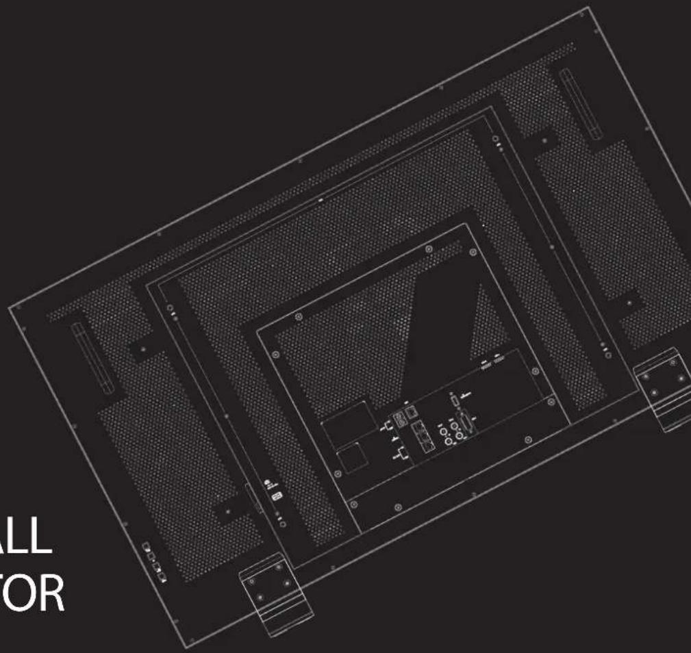
S-32P / S-42P / S-46P / S-55P ALL PART (FRONT / REAR)  03 CONTROLS & FUNCTIONS
FRONT & REAR (Buttons)
• [POWER]
\- Used to turn the power on and off.• [POWER INDICATOR] Lamp
- Indicates the condition and power status of the unit. - The lamp turns off when the power is disconnected. - Standby mode is indicated by a red LED light. - Normal (active) mode is indicated by a Green LED light. - If the power is disconnected and then connected again while the monitor is working, it is restored to the previous condition.• [USB]
\- This terminal is used to upgrade the firmware using the USB Thumb Drive or calibrate the color using the calibration software made by TVLogic.• [IR] Sensor
\- Receives signals from the remote control.•[MENU] Button
- Used to activate the OSD menu. - When the OSD menu is activated, press this button to exit from the menu.•[UP] Button
- Used to move upward within the main menu and sub menu when OSD menu is activated. - Increase the setting value in the adjustment mode.•[DOWN] Button
- Used to move downward within the main menu and sub menu when OSD menu is activated. - Decrease the setting value in the adjustment mode.•[ENTER] Button
\- Press the button to confirm the setting.03 CONTROLS & FUNCTIONS
REAR
• [SPF-A] IN (SFP Optical Interface) \- Optical interface for SDI input signal. The SFP module for HD/SD SDI signal can be connected. • [SPF-B] IN (SFP Optical Interface) \- Optical interface for SDI input signal. The SFP module for HD/SD SDI signal can be connected. • [HDMI IN] \- Signal input terminal for HDMI signal. • [DVI IN] (DVI-I) \- Signal input terminal for DVI DIGITAL or DVI ANALOG signal. • [SDI IN] (BNC) \- Signal input terminal for SD/HD/3G-SDI signal. • [SDI OUT] (BNC) \- SDI signals which are input from [SDI IN A], [SDI IN B], [SFP IN A], [SFP IN B] can be output to SDI OUT ports. • LAN (RJ-45) \- Provides connection to control equipment for external monitor control. • [REMOTE] (RJ-45) \- Provides connection to control equipment (parallel switch) for external monitor control. - Features of each pin can be changed. •[RS422 IN & OUT] (RJ-45) \- Used to control the monitor with protocol provided by TVLogic or to support TSL protocol. •AUDIO IN (Phone Jack) \- Inputs the external audio. •AUDIO OUT (Phone Jack) \- Disembed the embedded audio signal from the input video signal and output the stereo sound through the phone jack. •[AC IN] \- 100 \~ 240V AC 50/60Hz • [POWER S/W] \- Power On/Off switch04 MENU TREE & ADJUSTMENT
MENU CONSTRUCTION & MENU CONTROL & MENU CONTROL SEQUENCE & MENU TREE
[1] Menu Construction [3] Menu Control Sequence
- This product can be controlled and set system-wise through OSD displayed on the screen. - The menu construction of this product is displayed as follows.  [2] Menu Control
\- You can control various functions using MENU, UP, DOWN, ENTER buttons on the rear of the monitor. \- Menu control sequence follows the order below: 1. Press the MENU button to activate the OSD menu. 2. Move to a desired menu by pressing UP/DOWN button. 3. Press the ENTER button to select the menu and move to a sub menu by pressing UP/DOWN button. 4. Press the ENTER button to select the desired sub menu. (The selected sub menu will be highlighted.) 5. Press the ENTER button to save the new value after adjusting the desired value by pressing UP/DOWN button. 6. Press the MENU button to return to the previous menu, and if there is no previous menu, the OSD menu will be removed from the screen.04 MENU TREE & ADJUSTMENT
MENU CONSTRUCTION & MENU CONTROL & MENU CONTROL SEQUENCE & MENU TREE
[4] Menu Tree| PICTURE | BRIGHTNESS |
| CONTRAST | |
| CHROMA | |
| SHARPNESS | |
| USER ASPECT H | |
| USER ASPECT V | |
| VIDEO | EHS(DE-INT) MODE |
| FAST MODE | |
| 3G FORMAT | |
| VIDEO RANGE SELECT | |
| TIME CODE ENABLE | |
| BLUE ONLY | |
| H/V DELAY | |
| H FLIP | |
| V FLIP | |
| CLOSED CAPTION | |
| CC INFO | |
| DECODE CHANNEL (608) | |
| CAPTION SERVICE (708) | |
| TELETEXT PAGE |
| COLOR | STANDARD |
| VIDEO RANGE | |
| PEAK LUMINANCE | |
| BLACK LEVEL | |
| COLOR GAMUT | |
| COLOR TEMP | |
| EOTF | |
| EETF | |
| HLG SG | |
| SG | |
| CAMERA LUT | |
| CUSTOM 3D LUT | |
| COLOR TEMP | |
| GAIN RED | |
| GAIN GREEN | |
| GAIN BLUE | |
| BIAS RED | |
| BIAS GREEN | |
| BIAS BLUE | |
| COLOR COPY | |
| COLOR SPACE | |
| GAMMA | |
| BACK LIGHT |
04 MENU TREE & ADJUSTMENT
MENU CONSTRUCTION & MENU CONTROL & MENU CONTROL SEQUENCE & MENU TREE
[4] Menu Tree| GPI | GPI PIN 1 ~ GPI PIN 8 |
| DHCP | |
| ID ADDRESS | |
| SUBNET MASK | |
| GATEWAY | |
| PORT NO. | |
| SETTING APPLY | |
| GROUP ID | |
| MONITOR ID | |
| UMD DISPLAY | |
| UMD BG. TRANS | |
| UMD FONT SIZE | |
| UMD CHARACTER | |
| UMD CHAR. COLOR | |
| D-UMD TALLY TYPE | |
| TALLY1 COLOR | |
| TALLY2 COLOR | |
| TALLY3 COLOR | |
| TALLY4 COLOR |
| MARKER | MARKER |
| CENTER MARKER | |
| SAFETY AREA | |
| FIT MARKER | |
| MARKER MAT | |
| MARKER COLOR | |
| MARKER THICKNESS | |
| USER MARKER H1 | |
| USER MARKER H2 | |
| USER MARKER V1 | |
| USER MARKER V2 | |
| SUB MARKER | |
| SUB CENTER MARKER | |
| SUB SAFETY AREA |
04 MENU TREE & ADJUSTMENT
MENU CONSTRUCTION & MENU CONTROL & MENU CONTROL SEQUENCE & MENU TREE
[4] Menu Tree| WAVEFORM | WAVEFORM DISPLAY |
| WAVEFORM INTENSITY | |
| WAVEFORM TRANS. | |
| WAVEFORM COLOR | |
| LINE WAVEFORM | |
| SELECT LINE POSITION | |
| LUMA(Y') ZONE CHECK | |
| LUMA(Y') ZONE ADJUST | |
| FOCUS ASSIST | |
| FOCUS ASSIST COLOR | |
| FOCUS ASSIST LEVEL | |
| RANGE ERROR | |
| Y MAX | |
| Y MIN | |
| C MAX | |
| C MIN | |
| Y PICTURE BLINK | |
| C PICTURE BLINK |
| AUDIO | LEVEL METER SELECT |
| LEVEL METER DISPLAY | |
| LEVEL METER REFERENCE | |
| LEVEL METER DECAY TIME | |
| LEVEL METER SIZE | |
| LEVEL METER POSITION | |
| VOLUME | |
| EM. AUDIO LEFT | |
| EM. AUDIO RIGHT | |
| SYSTEM | KEY LOCK NUMBER |
| KEY LOCK ENABLE | |
| OSD DISPLAY | |
| INTERNAL PATTERN | |
| ECO MODE TIMER | |
| ECO MODE LEVEL | |
| CONFIG. DATA | |
| SET DEFAULT | |
| S/W UPGRADE | |
| VERSION |
05 MENU OPERATIONS
[1] PICTURE
• BRIGHTNESS
\- Indicate the brightness (Offset) setting level of the current screen. The setting range is from -100 to 100.• CONTRAST
\- Indicate the contrast (Gain) setting level of the current screen. The setting range is from -100 to 100.- CHROMA
\- Indicate the chroma (Saturation) setting level of the current screen. The setting range is from -50 to 50.• SHARPNESS
\- Indicate the sharpness setting level of the current screen. The setting range is from -10 to 10.- USER ASPECT H
- Used to adjust the horizontal size of the screen. - The setting range is from 0 to 1920. - Activated only when the [SCAN] mode is set to [USER ASPECT].- USER ASPECT V
- Used to adjust the vertical size of the screen. - The setting range is from 0 to 1080. - Activated only when the [SCAN] mode is set to [USER ASPECT].05 MENU OPERATIONS
[2] VIDEO
| Video & Display | S-46P |
| EHS(DE-INT) MODE | OFF |
| FAST MODE | OFF |
| 3G FORMAT | NORMAL |
| VIDEO RANGE SELECT | FULL |
| TIME CODE ENABLE | OFF |
| BLUE ONLY | OFF |
| H/V DELAY | OFF |
| H FLIP | OFF |
| V FLIP | OFF |
| Closed Caption | |
| CLOSED CAPTION | ANC(608/708) |
| CC INFO | CC608(ANC) |
| DECODE CHANNEL(608) | CC 1 |
| CAPTION SERVICE(708) | Service 1 |
| TELETEXT PAGE | 101 |
• EHS(DE-INT) MODE
- This item toggles the 4:4:4 video processing filter On/Off. - To eliminate ringing artifacts under 4:2:2 sources, please set this Filter to ON or OFF.- FAST MODE
- Used to minimize the time delay between arrival of the serial electrical signal at the monitor input and the light output from the screen. - Since this function is to minimize the de-interlacing delay, it will not be effective under progressive format. - This function is useful when the input signal is the fast moving video, and also useful to reduce the delay time between the video and the audio.• 3G FORMAT
- Used to select input format of SDI 3G A/B support. - The available modes are as follows. NORMAL MODE A 444 10BIT\_YCbCr A 444 10BIT\_RGB A 444 12BIT\_YCbCr, A 444 12BIT\_RGB A 422 12BIT\_YCbCr B 444 10/12BIT\_YCbCr B 444 10/12BIT\_RGB B 422 12BIT\_YCbCr B 422 10BIT\_YCbCr 50/60P - Automatically detect the signal when the payload signal appears in NORMAL mode.•VIDEO RANGE SELECT
- Used to set the VIDEO RANGE of input signal. - Available modes are [NARROW] and [FULL].• TIME CODE ENABLE
- Used to display the Time Code. - Available modes are [OFF], [VITC] and [LTC].- BLUE ONLY
- Used to remove red and green from the input signal and display the screen only under a blue signal. - Available modes are [OFF], [BLUE], [MONO].• H/V DELAY
- Used to check the Ancillary (ANC) data. - Available modes are [OFF] and [ON].• H FLIP (Not supported)
\- Used to flip the displayed image horizontally.• V FLIP (Not supported)
\- Used to flip the displayed image vertically.05 MENU OPERATIONS
[2] VIDEO
| Video & Display | S-46P |
| EHS(DE-INT) MODE | OFF |
| FAST MODE | OFF |
| 3G FORMAT | NORMAL |
| VIDEO RANGE SELECT | FULL |
| TIME CODE ENABLE | OFF |
| BLUE ONLY | OFF |
| H/V DELAY | OFF |
| H FLIP | OFF |
| V FLIP | OFF |
| Closed Caption | |
| CLOSED CAPTION | ANC(608/708) |
| CC INFO | CC608(ANC) |
| DECODE CHANNEL(608) | CC 1 |
| CAPTION SERVICE(708) | Service 1 |
| TELETEXT PAGE | 101 |
•CLOSED CAPTION
- Used to set the Closed Caption. - Available modes are [OFF], [608(ANC)], [608(Line21)], [708], and [OP47]. - The Closed Captions which meet 608: CEA- 608-B, 708: CEA-708-C, OP47 standard are only displayed on the screen.• CC INFO (CLOSED CAPTION INFO)
\- Displays the CC(Closed Caption) information which the monitor currently receives.• DECODE CHANNEL (608)
- Sets the channel of Closed Caption 608. - Available modes are [CC1] to [CC4].•CAPTION SERVICE (708)
- Sets the service of Closed Caption 708. - Available modes are [Service1] to [Service6].• TELETEXT PAGE
- Sets the page of OP47. - Available modes are [801] to [8FF].05 MENU OPERATIONS
[3] COLOR
| Color | 1/2 | S-46P |
| STANDARD | HD | |
| VIDEO RANGE | NARROW | |
| PEAK LUMINANCE | 120 | |
| BLACK LEVEL | 0.010 | |
| COLOR GAMUT | REC. 709 | |
| COLOR TEMP. | 6500K | |
| EOTF | 2.4 | |
| EETF | OFF | |
| HLG SG | OFF | |
| SG | 1.2 | |
| CAMERA LUT | OFF | |
| CUSTOM 3D LUT | SETTING | |
• STANDARD
- Used to select the color and dynamic range of the screen. - Available options are [HD], [UHD], [DCI-P3], [PQ], [HLG], [SLOG3] and [USER1/2/3]. \*The sub menus are activated only in the USER1/2/3 mode.•VIDEO RANGE
\- Used to select the range of digital video signal. [NARROW]: When the input signal is Y': 16\~235, CbCr: 16\~240 (8bit) Y': 64\~940, CbCr: 64-960 (10bit) [SDI FULL]: When the input signal is 1\~254 (8bit), 4\~1019 (10bit) \- This menu is activated only in the USER1/2/3 mode.- PEAK LUMINANCE
- Used to select the Peak Luminance of the monitor. - This function is activated only when STANDARD is set to USER1/2/3 and then EOTF is set to PQ or HLG or SLOG3. - Available options are [120], [200], [300], [400], [500], [600], [700], [800], [900], [1000], [2000], [3000], [4000], [5000], [6000], [7000], [8000], [9000] and [10000].- BLACK LEVEL
- The minimum black level of the video signal can be set differently depending on the performance of the monitor or the lighting environment. - This menu is activated only in the USER1/2/3 mode. - Available modes are from [0.000] to [0.010] with 0.001 increment, from [0.010] to [0.100] with 0.010 increment, from [0.100] to [0.900] with 0.100 increment.• COLOR GAMUT
- Used to select the standard color gamut. - Available options are [BT.709], [SMPTE-C], [EBU], [D-CINEMA], [BT.2020], and [NATIVE]. - This menu is activated only in the [USER1/2/3] mode.• COLOR TEMP. (Color Temperature)
- Controls the color temperature and allows instant access to preset the color temperature settings. - Available options are [3200K], [5000K], [5600K], [6500K], [9300K], [CUSTOM 1], [CUSTOM 2], [CUSTOM 3]. - R/G/B Gain, R/G/B Bias(=Offset) and Color Copy menus activate only in the CUSTOM mode. - Backlight value is adjustable for each color temperature. - This menu is activated only in the [USER1/2/3] mode.• EOTF
- Selects the electrophotic conversion functions (ex: Gamma or HDR curve). - Available options are [2.2], [2.4], [2.6], [PQ], [HLG] and [SLOG3]. - This menu is activated only in the [USER1/2/3] mode.05 MENU OPERATIONS
[3] COLOR
| Color | 1/2 | S-46P |
| STANDARD | HD | |
| VIDEO RANGE | NARROW | |
| PEAK LUMINANCE | 120 | |
| BLACK LEVEL | 0.010 | |
| COLOR GAMUT | REC. 709 | |
| COLOR TEMP. | 6500K | |
| EOTF | 2.4 | |
| EETF | OFF | |
| HLG SG | OFF | |
| SG | 1.2 | |
| BACK LIGHT | OFF | |
| CUSTOM 3D LUT | SETTING |
• EETF (Electrical-Electrical Transfer Function)
- It is a conversion function that expresses (without clipping) the HDR image within the actual luminance range (black level & peak luminance) that the monitor can express. - In case of [ON] mode, the HDR image is converted within the range of set peak luminance and black level. - In case of [OFF] mode, the video signals outside the set range will be clipped. - Available options are [OFF] and [ON]. - This menu is activated only when the [EOTF] is set to [PQ] or [SLOG3].•HLG SG
- Used to set the System Gamma of the HLG mode. - In [ON] mode, the value of the System Gamma changes automatically according to the previously set peak luminance. When it is [OFF], the value is set to default value of [1.2]. - This menu is activated only when the [EOTF] is set to [HLG]. - This menu is activated only in the [USER1/2/3] mode.• SG (System Gamma)
- The System Gamma of HLG is automatically calculated and displayed according to the set peak luminance. - This menu is activated only when the [EOTF] is set to [HLG] and the [HLG SG] is set to [ON].• CAMERA LUT (Not supported)
\- Used to change the Camera LUT.•CUSTOM 3D LUT (Not supported)
\- Used to apply the custom 3D LUT File.05 MENU OPERATIONS
[3] COLOR
bar
| Color | 2/2 | S-46P | |---|---|---| | COLOR Temp. | 6500K | | | GAIN RED | 0 | | | GAIN GREEN | 0 | | | GAIN BLUE | 0 | | | BIAS RED | 0 | | | BIAS GREEN | 0 | | | BIAS BLUE | 0 | | | COLOR COPY | 3200K | | | COLOR SPACE | NORMAL | | | GAMMA | 2.4 | | | BACK LIGHT | 0 | |• COLOR TEMP. (Color Temperature)
- Controls the color temperature and allows instant access to preset the color temperature settings. - Available options are [3200K], [5000K], [5600K], [6500K], [9300K], [CUSTOM 1], [CUSTOM 2], [CUSTOM 3]. - [R/G/B Gain], [R/G/B Bias] and [COLOR COPY] menus activate only in the [CUSTOM] mode. - Backlight value is adjustable for each color temperature.• GAIN RED / GREEN / BLUE
- Used to set Red/Green/Blue Gain(or Picture, Contrast) level. - Available range is -256 to 255. - These menus are activated in CUSTOME 1/2/3 modes only.• BIAS RED / GREEN / BLUE
- Used to set Red/Green/Blue Bias (or Offset. Mainly affects on Black level). - Available range is [-100] to [100]. - These menus are activated in CUSTOM 1/2/3 modes only.• COLOR COPY
- Used to copy the R/G/B Gain value of pre-stored color temperature settings. - In User mode, find and select the color temperature to be used with the Knob and press the knob button to copy and apply the Gain value to [GAIN RED], [GAIN GREEN], [GAIN BLUE]. - This menu is activated in CUSTOM 1/2/3 modes only.• COLOR SPACE
- Used to select the color output format. - This menu is activated only when [STANDARD] is set to [HD]. - Available options are [BT.709], [SMPTE-C], [EBU], [D-CINEMA], [BT.2020], and [NATIVE].• GAMMA
- Used to change the Gamma Curve between [1.0] and [3.0] with 0.05 increment. - This menu is activated only when [STANDARD] is set to [HD].- BACK LIGHT
- Adjusts the current value of the backlight of the LCD panel. - Available values are from [0] to [100].05 MENU OPERATIONS
[4] GPI
| GPI | 1/3 | S-46P |
| PIN 1 | NONE | |
| PIN 2 | SDI CHANNEL | |
| PIN 3 | HDMI CHANNEL | |
| PIN 4 | UNDER SCAN | |
| PIN 5 | ASPECT | |
| PIN 6 | H/V DELAY | |
| PIN 7 | POWER ON | |
| PIN 8 | GND | |
| DHCP | ON | |
| IP ADDRESS | 192.168.101.171 | |
| SUBNET MASK | 255.255.255.0 | |
| GATEWAY | 192.168.101.1 | |
| PORT NO. | 10262 | |
| SETTING APPLY | ON | |
• GPI PIN 1 \~ PIN 8
- This item activates/deactivates the REMOTE function. - The user may connect an RJ-45 jack to the REMOTE terminal on the rear of the unit and designate a function for each pin. - The default settings are as follows: PIN1 : NONE / PIN2 : NONE / PIN3 : NONE PIN4 : NONE / PIN5 : NONE / PIN6: NONE PIN 7 is POWER ON/OFF use only and PIN 8 is GND. - The selectable values are as shown on the Right.• The pin positions are as follows :
REMOTE (RJ-45) 1: Pin 2: Pin2 3: Pin3 4: Pin4 5: Pin5 6: Pin6 7: Pin7 8: GND •DHCP
\- Used to set DHCP.• IP ADDRESS / SUBNET MASK / GATEWAY
\- Used to set the Network address.•PORT NO
\- Used to set the port number. The default value is [10262].- SETTING APPLY
\- Used to apply the settings.| PIN No. Settable Values | |
| PIN1~6 | NONESDI A CHANNELSDI B CHANNELPBP CHANNELHDMI CHANNELSFP A CHANNELSFP B CHANNELDVI CHANNEL1:1 SCAN, ASPECTH/V DELAY, BLUE ONLY, MONO16:9 MARKER, 4:3 MARKER4:3 ON AIR MARKER15:9 MARKER, 14:9 MARKER13:9 MARKER, 1.85:1 MARKER2.35:1 MARKER1.85:1 & 4:3 MARKERCENTER MARKERSAFETY AREA 80%SAFETY AREA 85%SAFETY AREA 88%SAFETY AREA 90%SAFETY AREA 93%SAFETY AREA 100% |
| PIN 7 | POWER ON/OFF CONTROL |
| PIN 8 | GND |
05 MENU OPERATIONS
[4] GPI
| GPI | 2/3 | S-46P |
| GROUP ID | 0 | |
| MONITOR ID | 0 | |
| UMD DISPLAY | OFF | |
| UMD BG. TRANS | SCALE DOWN | |
| UMD FONT SIZE | LARGE | |
| CHANNEL 1 | ||
| UMD CHAR. COLOR | 0 | |
| UMD CHAR. COLOR | HDMI CHANNEL | |
| D-UMD TALLY TYPE | DEFAULT | |
| TALLY1 COLOR | OFF | |
| TALLY2 COLOR | OFF | |
| TALLY3 COLOR | OFF | |
| TALLY4 COLOR | OFF | |
- GROUP ID
\- Used to group the monitors and control the monitors by group when you control the monitors with the protocol provided by TVLogic, using RS-422/485 communication or Network. \- Available setting is from [0] to [16].• MONITOR ID
\- Used to set the ID of each monitor when you control monitors with TVLogic control protocol using RS-422/485 communication or Network or when you set and use [DYNAMIC UMD] in [UMD DISPLAY] menu. \- Available values are from [0] to [124]. \- In the PBP mode, the right screen's ID is automatically set to 'MONITOR ID setting value +1'.• UMD DISPLAY
- Used to set the Input signal ID mode. - Available modes: [UMD], [ANC], [D-UMD(TSL3 S-8C)], [D-UMD(TSL3 S-16C)], [D-UMD(TSL3 D-8C)], [D-UMD(TSL5 S-8C)], [D-UMD(TSL5 S-16C)], [D-UMD(TSL5 D-8C)], [Ember+], [OFF] - When the UMD menu is set, a black bar is created at the bottom of the monitor, the text or tally data is displayed in it, and the image is displayed on the screen by adjusting the screen ratio by the vertical size of the created bar. - In the [USER ASPECT] mode, the UMD bar appears translucent and is displayed on the screen in the size set in [USER ASPECT]. - UMD: Displays the 8 characters which the user set in USER CHARACTER menu. - ANC: Displays the characters embedded in SDI signal. - D-UMD(S-8C): Displays the 8 characters and the tally signal which are input from the TSL protocol(V3.1). • D-UMD(S-16C): Displays the 16 characters and the tally signal which are input from the TSL protocol(V3.1). • D-UMD(D-8C): Displays the two pairs of 8 characters and the two pairs of the tally signal which are input from the TSL protocol(V3.1). \- In the PBP mode, only [D-UMD(S-8C)] operates even though [D-UMD(S-8C)], [D-UMD(S-16C)] or [D-UMD(D-8C)] is set. \- In the PBP mode, [D-UMD(S-8C)] is activated at the bottom left of the screen, and [D-UMD(S-8C)] is activated at the bottom right of the screen, and both can be set individually.• UMD BG. TRANS.
(UMD Background Transparency)
- Used to set the transparency of the UMD background. - Available modes are [OPAQUE], [TRANS], [SCALE DOWN].• UMD FONT SIZE
- Used to adjust the size of UMD font. - Available modes are [SMALL], [NORMAL] and [LARGE].05 MENU OPERATIONS
[4] GPI
| GPI | 2/3 | S-46P |
| GROUP ID | 0 | |
| MONITOR ID | 0 | |
| UMD DISPLAY | OFF | |
| UMD BG. TRANS | SCALE DOWN | |
| UMD FONT SIZE | LARGE | |
| CHANNEL 1 | ||
| UMD CHAR. COLOR | 0 | |
| UMD CHAR. COLOR | HDMI CHANNEL | |
| D-UMD TALLY TYPE | DEFAULT | |
| TALLY1 COLOR | OFF | |
| TALLY2 COLOR | OFF | |
| TALLY3 COLOR | OFF | |
| TALLY4 COLOR | OFF | |
• UMD CHARACTER
\- Used to customize the characters which are displayed when UMD is set in [UMD DISPLAY] menu. \- Available characters are lowercase and uppercase alphabet letters, numbers, and special symbols.• UMD CHAR. COLOR (UMD Character Color)
\- Used to set the character color of UMD. \- Available options are [WHITE], [RED], [GREEN], [BLUE], [YELLOW], [CYAN], [MAGENTA].| GPI | 3/3 | S-46P |
| GROUP ID | 0 | |
| MONITOR ID | 0 | |
| UMD DISPLAY | OFF | |
| UMD BG. TRANS | SCALE DOWN | |
| UMD FONT SIZE | LARGE | |
| CHANNEL 2 | ||
| UMD CHAR. COLOR | 0 | |
| UMD CHAR. COLOR | HDMI CHANNEL | |
| D-UMD TALLY TYPE | DEFAULT | |
| TALLY1 COLOR | OFF | |
| TALLY2 COLOR | OFF | |
| TALLY3 COLOR | OFF | |
| TALLY4 COLOR | OFF | |
• D-UMD TALLY TYPE
- Used to set the tally type in the [D-UMD(D-8C)]. - Available modes: [DEFAULT], [USER BG], [USER COLOR], [CHARACTER], [BG. COLOR], [USER TALLY], [USER CHAR], \- DEFAULT: Existing TVLogic operating system(VRT). \- USER COLOR: The user is allowed to adjust the color of each tally. \- When [USER COLOR], [USER TALLY], [USER CHAR] or [USER BG] is selected, [TALLY1 COLOR] \~ [TALLY4 COLOR] are activated.• TALLY1 COLOR \~ TALLY4 COLOR
- Used to set the color of each TALLY1, TALLY2, TALLY3 and TALLY4. - Available colors are [WHITE], [RED], [GREEN], [BLUE], [YELLOW], [CYAN] and [MAGENTA].05 MENU OPERATIONS
[5] MARKER
• MARKER
- Used to select the operation of the marker. - Available marker types: [OFF], [16:9], [4:3], [4:3 ON AIR], [15:9], [14:9], [13:9], [1.85:1], [2.35:1], [1.85:1\_4:3], [USER]• CENTER MARKER
- Displays the Center Marker on the screen. - Available modes are [ON] and [OFF].• SAFETY AREA
- Used to display the safety area which doesn't cut the closed caption by Over Scan. - Available sizes are [80%], [85%], [88%], [90%], [93%], [100%], [EBU ACTION 16:9], [EBU GRAPHIC 16:9], [EBU ACTION 14:9], [EBU GRAPHIC 14:9], [EBU ACTION 4:3] and [EBU GRAPHIC 4:3].• FIT MARKER
- Used to activate or inactivate the Fit Marker function. - When the Marker type is selected in the [MARKER] menu, a border line of the Safety Area will be displayed inside the Marker area. - Images below show the difference between Fit Marker [ON] and [OFF]. natural_image
Abstract color block composition with red, green, and blue vertical bars (no text or symbols)natural_image
Abstract color block composition with red, green, blue, and black outlines (no text or symbols)• MARKER MAT
- Used to set the transparency level outside of the MARKER area. - Available levels are from [OFF](transparent) to [7](Black). - The higher the level is, the darker the outside of the MARKER area is.• MARKER COLOR
- Used to set the color of the MARKER lines. - Available colors are [WHITE], [YELLOW], [CYAN], [GREEN], [MAGENTA], [RED], [BLUE], [BLACK].• MARKER THICKNESS
- Used to set the thickness of the MARKER lines. - Thickness level is from [1] to [7].05 MENU OPERATIONS
[5] MARKER
 \*USER MARKER H1/H2/V1/V2 activate when the MARKER menu is set to USER mode.- USER MARKER H1
- Used to set the position of the first horizontal marker line. - Adjustment rage is from [0] to [1920].- USER MARKER H2
- Used to set the position of the second horizontal marker line. - Adjustment rage is from [0] to [1920].- USER MARKER V1
- Used to set the position of the first vertical marker line. - Adjustment rage is from [0] to [1080].- USER MARKER V2
- Used to set the position of the second vertical marker line. - Adjustment rage is from [0] to [1080].• SUB MARKER
- Used to display the additional Marker on the screen. - Available Sub Marker types are [OFF], [16:9], [4:3], [4:3 ON AIR], [15:9], [14:9], [13:9], [1.85:1], [2.35:1], [1.85:1\_4:3].• SUB CENTER MARKER
- Used to display the additional Center Marker on the screen. - Available modes are [ON] and [OFF].• SAFETY AREA
- Used to display the additional safety area which doesn't cut the closed caption by Over Scan. - Available size: [80%], [85%], [88%], [90%], [93%], [100%], [EBU ACTION 16:9], [EBU GRAPHIC 16:9], [EBU ACTION 14:9], [EBU GRAPHIC 14:9], [EBU ACTION 4:3], [EBU GRAPHIC 4:3]05 MENU OPERATIONS
[6] MISC FEATURES
Misc Features
S-46P SDI OUTPUT-A INPUT CHANNEL - A SDI OUTPUT-A INPUT CHANNEL - A• SDI OUTPUT A/B
\- Used to select the input signal which is output to SDI OUTPUT port. \- SDI signal only can be output, and the selectable inputs are [SDI IN A], [SDI IN B], [SFP IN A], [SFP IN B].05 MENU OPERATIONS
[7] WAVEFORM & FOCUS
bar
Waveform & Focus | Parameter | Value | |---|---| | WAVE FORM DISPLAY | OFF | | WAVE FORM INTENSITY | 0 | | WAVE FORM TRANS. | BLEND | | WAVE FORM COLOR | WHITE | | LINE WAVE FORM | ON | | SELECT LINE POSITION | 0 | | LUMA(Y') ZONE CHECK | OFF | | LUMA(Y') ZONE ADJUST | 0 | | FOCUS ASSIST | OFF | | FOCUS ASSIST COLOR | WHITE | | FOCUS ASSIST LEVEL | 0 | | RANGE ERROR | ON | | Y MAX | 1 | | Y MIN | 1 | | C MAX | 1 | | C MIN | 1 | | Y PICTURE BLINK | OFF | | C PICTURE BLINK | OFF |• WAVEFORM DISPLAY
- This function sets the mode of Waveform and Vector Scope. Available options are different depending on the Input signal. - When the input signal is YCbCr, the available modes are [OFF], [WAVEFORM], [VECTOR SCOPE], [WAVEFORM WIDE], [WAVEFORM\_YCbCr], [WAVEFORM RGB], [WAVE VECTOR].• WAVEFORM INTENSITY
- Controls the brightness of Waveform and Vector Scope display. - Available values are between [0] \~ [63]. The higher the value is, the brighter the waveform is displayed.• WAVEFORM TRANS. (Waveform Transparency)
- Controls the transparency level of the Waveform/Vector. - Available options are [OPAQUE] and [BLEND]. - If the Waveform/Vector overlaps the main OSD even when the option is set to [OPAQUE], it will be automatically changed to [BLEND] mode. When the main OSD disappears or the Waveform/Vector doesn't overlap the main OSD, it automatically becomes the [OPAQUE] mode.• WAVEFORM COLOR
- This item selects the color of Waveform. - Available options are [GREEN] and [WHITE].•LINE WAVEFORM
\- When this function is set [ON], the data of the selected line is only displayed on the [WAVEFORM] and [VECTOR SCOPE].- SELECT LINE POSITION
- Used to select the specific horizontal line for Waveform and Vector Scope. - This menu is available when [LINE WAVEFORM] is activated. - If you want to adjust a desired horizontal line, you can select [WAVEFORM] or other modes in [WAVE FORM DISPLAY] menu and then select the specific vertical line using the [UP]/ [DOWN] button. - The control range varies according to the resolution of the input signal. (SDI signal) • PAL: Min. 1, Max. 625 • NTSC: Min. 1, Max. 525 • 720p: Min. 1, Max. 750 • 1080i: Min. 1, Max. 1125 • 1080p: Min. 1, Max. 112505 MENU OPERATIONS
[7] WAVEFORM & FOCUS
bar
Waveform & Focus | Parameter | Value | |---|---| | WAVE FORM DISPLAY | OFF | | WAVE FORM INTENSITY | 0 | | WAVE FORM TRANS. | BLEND | | WAVE FORM COLOR | WHITE | | LINE WAVE FORM | ON | | SELECT LINE POSITION | 0 | | LUMA(Y') ZONE CHECK | OFF | | LUMA(Y') ZONE ADJUST | 0 | | FOCUS ASSIST | OFF | | FOCUS ASSIST COLOR | WHITE | | FOCUS ASSIST LEVEL | 0 | | RANGE ERROR | ON | | Y MAX | 1 | | Y MIN | 1 | | C MAX | 1 | | C MIN | 1 | | Y PICTURE BLINK | OFF | | C PICTURE BLINK | OFF |• LUMA(Y') ZONE CHECK
- Analyzes the Luma(Y') level of the input image and displays the selected zone on the screen. - Available modes are [Color Pattern] and [Zebra Pattern]. - After each pixel's Y' level is analyzed, it is displayed as a certain color or zebra pattern according to the Index on the right side of the screen. - When a pixel's Y' level is under 0%(16), the pixel is displayed as green color or green diagonal lines, and over 100%(235) as red color or red diagonal lines. - When the Y' level of a pixel is between 0\~100%, the pixel is displayed as Gray level, except for selected Luma Zone. - In the [Color Pattern] mode, the zone the user adjusted is displayed as Yellow (10% lower zone), Pink (±2.5%), Cyan (10% upper zone). \- In the [Zebra Pattern] mode, ±5% of the selected Y' Level will be displayed as diagonal lines.• LUMA(Y') ZONE ADJUST
- Used to set the Y' level to be colored Yellow, Pink and Cyan in [Color Pattern] mode, or to set Y' level zone to be displayed with diagonal lines in [Zebra Pattern] mode simply by scrolling with the Knob. - Available values are [0]% \~ [100]%.• FOCUS ASSIST
- Focus Assist helps the shooters to easily find out the exact area in the picture that is in focus, simply by adding colors on the boundaries of the subject in the picture. - Available modes are [COLOR ON] and [MONO ON]. • COLOR ON: The boundary of the area with good focus is colored with the designated color. - MONO ON: The boundary of the area with good focus is colored with the designated color, while the rest of the areas(pixels) receive only Y'(Luma) signals and become black & white image.• FOCUS ASSIST COLOR
- Used to select a color for Focus Assist among [RED], [GREEN], [BLUE], [WHITE]. - This feature is available only when the [FOCUS ASSIST] mode is activated.• FOCUS ASSIST LEVEL
- Used to set the edge difference value between the edges in an image. - Available values are from [0] to [100]. Larger value means more sophisticated detail detection. - The color designated in [FOCUS ASSIST COLOR] menu is displayed on the boundaries when the difference of the edges exceeds the previously set value. - This feature is available only when the [FOCUS ASSIST] mode is activated.05 MENU OPERATIONS
[7] WAVEFORM & FOCUS
bar
Waveform & Focus | Parameter | Value | |---|---| | WAVE FORM DISPLAY | OFF | | WAVE FORM INTENSITY | 0 | | WAVE FORM TRANS. | BLEND | | WAVE FORM COLOR | WHITE | | LINE WAVE FORM | ON | | SELECT LINE POSITION | 0 | | LUMA(Y') ZONE CHECK | OFF | | LUMA(Y') ZONE ADJUST | 0 | | FOCUS ASSIST | OFF | | FOCUS ASSIST COLOR | WHITE | | FOCUS ASSIST LEVEL | 0 | | RANGE ERROR | ON | | Y MAX | 1 | | Y MIN | 1 | | C MAX | 1 | | C MIN | 1 | | Y PICTURE BLINK | OFF | | C PICTURE BLINK | OFF |• RANGE ERROR
- Used to set whether or not to activate [Y MAX], [Y MIN], [C MAX], [C MIN], [Y PICTURE BLINK] and [C PICTURE BLINK] functions. - The values which are set in [Y MAX], [Y MIN], [C MAX], [C MIN] menu are indicated in Waveform set in [WAVE FORM DISPLAY] menu. - If [Y PICTURE BLINK] or [C PICTURE BLINK] is enabled, the section of image that exceeds the selected values of [Y MAX], [Y MIN], [C MAX] and [C MIN] shall blink. - RANGE ERROR function doesn't support the RGB signals.• Y MAX
- Used to set the maximum luma(Y') level. - Available range is from [0] to [254]. - Pixels with values exceeding the maximum Y' level blink in the screen and are displayed in red on the Waveform.•Y MIN
- Used to set the minimum luma(Y') level. - Available range is from [0] to [254]. - Pixels with values below the minimum Y' level blink in the screen and are displayed in red on the Waveform.• C MAX
- Used to set the maximum chroma(C') level. - Available range is from [0] to [254]. - Pixels with values exceeding the maximum C' level blink in the screen and are displayed in red on the Waveform.• C MIN
- Used to set the minimum chroma(C') level. - Available range is from [0] to [254]. - Pixels with values below the minimum C' level blink in the screen and are displayed in red on the Waveform.• Y PICTURE BLINK
\- Used to trigger selections of image that exceed [Y MAX] and [Y MIN] to blink.• C PICTURE BLINK
\- Used to trigger selections of image that exceed [C MAX] and [C MIN] to blink.05 MENU OPERATIONS
[8] AUDIO
• LEVEL METER SELECT
- Used to control the embedded Audio Level Meters. - Available modes are [OFF], [16CH], [G2+G4], [G1+G4], [G1+G3], [G3+G4], [G2+G3], [G1+G2].• LEVEL METER DISPLAY
- Used to set the display method for audio level meter. - Available modes are [PAIR] and [GROUP]. - When the input signal is HDMI, the mode is fixed to [PAIR].• LEVEL METER REFERENCE
- Used to set Audio Level Meter default. - Available values are [-18dB] and [-20dB]. - The audio within the selected value is displayed in green on the Audio Level Meter. The audio which exceeds the selected value is displayed in yellow on the Audio Level Meter. - The audio exceeding -4dB is displayed in red on the Audio Level Meter.• LEVEL METER DECAY TIME
- Used to set the reduction time of the maximum indication of audio signals. - Available values are from [0] to [100]. Larger values indicate a longer time to display. - The higher the value is set, the longer time it takes for the indication bars to decay.• LEVEL METER SIZE
- Used to set the size of the Audio Level Meters. - Available modes are [SMALL], [SMALL TRANSLUCENT], [NORMAL], [NORMAL TRANSLUCENT], [LARGE] and [LARGE TRANSLUCENT]. - In [SMALL], [NORMAL] and [LARGE] modes, the Audio Level Meter appears opaque. - In [SMALL TRANSLUCENT], [NORMAL TRANSLUCENT] and [LARGE TRANSLUCENT] modes, the Audio Level Meter appears semitransparent.• LEVEL METER POSITION
- Used to set the position of the Audio Level Meters. - Available modes are as below. • HORIZONTAL-TOP: Displays 8 channels of the audio level meter on the top left and 8 channels of audio level meter on the top right horizontally. • VERTICAL-MIDDLE: Displays 8 channels of the audio level meter on the center left and 8 channels of the audio level meter on the center right vertically. • VERTICAL-BOTTOM: Displays 8 channels of the audio level meter on the bottom left and 8 channels of the audio level meter on the bottom right vertically.• VOLUME
- Used to adjust the output volume of the internal speakers or [AUDIO OUT] on the back of the monitor. - Adjustment range is from [0] to [50].• EM. AUDIO LEFT (Embedded Audio Left)
- Used to set the embedded audio channel for left audio out of [AUDIO OUT] terminal on the back of the monitor. - Available modes are [OFF], [CH 01] to [CH 16], and [Ext. AUDIO]. - In HDMI mode, the audio channel is fixed to [CH 01].•EM. AUDIO RIGHT (Embedded Audio Right)
- Used to set the embedded audio channel for right audio out of [AUDIO OUT] terminal on the back of the monitor. - Available modes are [OFF], [CH 01] to [CH 16], and [Ext. AUDIO]. - In HDMI mode, the audio channel is fixed to [CH 02].05 MENU OPERATIONS
[9] SYSTEM
- KEY LOCK NUMBER
- Used to set a password for the monitor lock function. - Up to 16 characters can be set using numbers and alphabets.- KEY LOCK ENABLE
- Used to lock all buttons except for power button. - If any button other than the power is pressed, a password input window will appear. - Enter the password set through the [KEY LOCK NUMBER] menu to unlock.- OSD DISPLAY
- Used to set the display time for the OSD menu. - Available modes are [CONTINUE], [5 SEC], [10 SEC], [15 SEC], [20 SEC].•INTERNAL PATTERN
- Generates the internal WHITE pattern. - The selectable range of WHITE pattern is from 0% to 100% with 5% increment.• ECO MODE TIMER
- Used to decrease the brightness of the screen automatically to reduce the power consumption when there is no signal. - When the monitor receives the signal, the brightness of the screen maintains the adjusted level. - The time to trigger the ECO MODE can be set. - Available options are [OFF], [30 sec], [60 sec].• ECO MODE LEVEL
- Used to set the brightness level when the ECO MODE operates. - Available options are from [1] to [5].- CONFIG. DATA
- This function allows the user to save the current function settings of the monitor to the USB memory and load the saved configuration data to the monitor. [Copy to USB]: Insert the USB memory, select [START], type the file name, and select [ENTER], then the configuration data is saved to the USB memory. [Load From USB]: Insert the USB memory, select [START], then the saved configuration data files show up. Select the desired file, then the configuration data is loaded to the monitor.- SET DEFAULT
- Used to initialize OSD values to the factory default. - Initializes the values to 0 of [BRIGHTNESS], [CONTRAST], [CHROMA], [SHARPNESS].• S/W UPGRADE
\- Used to upgrade the firmware using the USB memory.- VERSION
\- Displays the version of Main board, FPGA, GPU, and APP.06 KEY FUNCTIONS
[1] PBP(Picture-by-Picture) / PIP(Picture-in-Picture)
• PBP(PIP) Mode Select
\- The user can select four modes of PBP function by pushing [INPUT SET] key on the remote control as follows. In order to avoid the confusion of terms, the PIP mode on the screen is collectively referred to as PBP.  PBP 1 (Picture by Picture)  PBP 2 (Left & Right)  PIP 3 (Picture in Picture)  PBP 4 (Top & Bottom)- Screen Select
\- In PBP mode, push the [0] key to select the desired display then control the desired functions. - The selected display will be highlighted.  Screen-1 selected  Screen-2 selected06 KEY FUNCTIONS
[2] USER ASPECT
\- This function allows the user to adjust the width/height display ratio as the user wants. 1. Access the [USER ASPECT] menu to activate the User Aspect mode. 2. Press [ENTER] button in the [USER ASPECT] mode and adjust the Width and the Height of the image using [UP] and [DOWN] button. USER ASPECT WIDTH +1920 HEIGHT +1080 natural_image
Color swatch bar with eight distinct solid color blocks (yellow, cyan, green, magenta, red, blue, black, dark blue) arranged horizontally on a white background.natural_image
Color swatch bar with eight distinct solid color blocks (white, yellow, cyan, green, magenta, red, blue, black, purple) and directional arrows on both sides (no text or symbols)natural_image
Color test pattern with eight solid color blocks (white, yellow, cyan, green, magenta, red, blue, black) on white background, no text or symbols present.natural_image
Color swatch bar with eight distinct solid color blocks (yellow, cyan, green, pink, red, blue, black, purple) and a light blue arrow pointing to the right side of the bars (no text or symbols)06 KEY FUNCTIONS
[3] WAVEFORM / VECTOR SCOPE
- WAVEFORM Y
\- Displays the Luma(Y') component of the input signal into waveform. natural_image
Scenic view of a waterfall surrounded by golden hills and a river, with an inset showing a 3D thermal or spectral visualization (no text or symbols on the main image)- Waveform Cb, Cr
\- Displays the Cb, Cr components of the input signal into waveform. natural_image
Aerial view of a mountainous landscape with a winding river and snow-covered slopes, overlaid with three inset panels (no visible text or symbols)- Vector Scope
- Displays the color components 'B-Y' and 'R-Y' of the input signals onto the X-Y axis. - Two different types of Vector Scopes are displayed depending on SD or HD input signals. - 100% and 75% scales are indicated on the Vector Scope. natural_image
Scenic view of a large waterfall surrounded by golden mountains and rocky terrain, with an inset radar chart showing the same landscape.06 KEY FUNCTIONS
[4] LINE SELECT (WAVEFORM / VECTOR SCOPE)
• Used to select a specific vertical line for WAVEFORM and VECTOR SCOPE. - This function works when the [LINE WAVEFORM] is activated. - To activate this function, go to [Waveform & Focus] > [WAVE FORM DISPLAY] and select [WAVEFORM] or other modes. And then, set [LINE WAVE FORM] ON and adjust the vertical line in [SELECT LINE POSITION] using [UP] and [DOWN] button. \- The selected line is indicated in White on the screen. \- Adjustment range varies according to the resolution of the input SDI signal. \- PAL: 0 \~ 625 \- NTSC: 0 \~ 525 \- 720p: 0 \~ 750 • 1080i/p: 0 \~ 1125 \- Adjustment range for HDMI signal varies according to the output resolution of the signal. \- The selected line is indicated on the screen as follows. 06 KEY FUNCTIONS
[5] LUMA (Y") ZONE CHECK
• COLOR PATTERN TYPE
- Displays the pixels with the designated Luma(Y') levels of the input image in colors. Pixels whose Y' level is over 100% are displayed as Red. Pixels whose Y' level is below 0% are displayed as Green. - Pixels with Y' levels which are designated by the user are displayed in following colors - yellow, pink, cyan. - Factory Default Y' (Border line between pink and yellow) level is 70%. The upper 2.5% and lower 2.5% zone from the Y' level set in [LUMA(Y') ZONE ADJUST] menu is displayed in Pink. The upper 10% zone from the Pink zone is displayed in Yellow, and the lower 10% zone from the Pink zone is displayed in Cyan. So, 25% zone is displayed in colors and the other 75% zone is displayed mono and white. \- This function is convenient to set the exposure or the lighting so that the skin tone or the specific color tone is correctly shot. natural_image
Close-up portrait of a young woman with dark hair and green leaf, no visible text or symbolsnatural_image
Portrait of a person with facial features in blue, yellow, and pink (no text or symbols visible)• ZEBRA PATTERN TYPE
\- Displays the pixels with the designated Luma(Y') levels of the input image in zebra pattern. Pixels whose Y' level is over 100% are displayed as red diagonal stripes. Pixels whose Y' level is below 0% are displayed as green diagonal stripes. \- Pixels with Y' levels which are designated by the user are displayed as black diagonal stripes. \- Factory Default Y' level is 70%. The pixels with Y' level from 65% to 75% are displayed as black zebra pattern. So, totally 10% zone is displayed as black diagonal stripes. \- This function is convenient to set the exposure or the lighting so that the skin tone or the specific color tone is correctly shot. natural_image
Close-up portrait of a young woman with dark hair and green leaf, no visible text or symbolsnatural_image
Close-up portrait of a person with visible facial features and green foliage, no text or symbols present.06 KEY FUNCTIONS
[6] FOCUS ASSIST
\- Focus Assist function assigns a color on the pixels of the shape or boundary of the image, which helps the user easily see which part of the image is in focus or out of focus. \- With this function, the user can easily differentiate the focused area from the out-focused area especially when shooting with a shallow depth of field. \- Available types are [COLOR ON] and [MONO ON]. • [COLOR ON]: Background image is original color type. • [MONO ON]: Background image is mono type. natural_image
Two women gently holding yellow tulips, smiling at each other (no text or symbols visible)natural_image
Black-and-white photo of two women in close proximity, one holding a rose (no visible text or symbols)06 KEY FUNCTIONS
[7] RANGE ERROR
\- Pixels with Y' or C' levels exceeding the designated levels adjusted in Y MAX, Y MIN, C MAX and C MIN menu shall blink. \- After the input signal's Luma(Y') and chroma information(C') are analyzed, if the input signal exceeds the designated maximum value or it is below the minimum value, the pixels shall blink. This function is to help the user to easily find out any unwanted levels of signals and set a better exposure. natural_image
Scenic mountain range with forested slopes and a distant lake under cloudy sky (no text or symbols visible)natural_image
Scenic landscape with snow-covered trees overlooking a calm lake under a clear sky (no text or symbols visible)06 KEY FUNCTIONS
[8] FIRMWARE UPGRADE
- The USB thumb drive which contains the F/W file is necessary for Firmware Upgrade. - Select the S/W UPGRADE in the SYSTEM menu. 1. Connect the USB thumb drive to the USB Slot on the front of the monitor. 2. Select CPU / FPGA / ALL in [S/W UPGRADE]. 3. When the USB thumb drive is properly connected, the S/W upgrade starts and the progress is displayed on the bottom left side of the screen. 4. If the USB thumb drive doesn't connect properly or there is no file in the specified location, the error message will be displayed on the bottom left side of the screen and the upgrade won't start. 5. In that case, check the USB thumb drive or the file location and try again. \- If the USB thumb drive is connected and then the power is turned off and on, the firmware upgrade automatically starts.07 VIDEO SUPPORT RESOLUTION
| INPUT SIGNAL INTERFACES SIGNAL FORMAT (SD SDI) | ||
| SD SDIsingle link | 720x487 (59.94i)720x576 (50i) | YCbCr 4:2:2 10bit |
| INPUT SIGNAL INTERFACES SIGNAL FORMAT (HD SDI) | ||
| HD SDISingle link | 1280x720 (23.98/24/25/29.97/30p)(50/59.94/60i) (24/25/29.97/30psf)1280x720(50/59.94/60P) | YCbCr 4:2:2 10bit |
| INPUT SIGNAL INTERFACES SIGNAL FORMAT (3G SDI) | ||
| 3G-SDI (A/B)Single link | 1920x1080 (60p/59.94p/50p) YCbCr 4:2:2 10bit | |
| 1920x1080 (30/29.97/25/24/23.98/30sF/29.97sF/25sF/24sF/23.98sF) | YCbCr 4:2:2 10bit /12bitYCbCr 4:4:4 10bit / 12bit | |
| INPUT SIGNAL INTERFACES SIGNAL FORMAT (HDMI ) | ||
| HDMISingle link | 1080p (60/59.94/50/30/29.97/25/24/23.98)1080i (60/59.94/50)720p (50/59.94/60p)480i(60) / 576i(50)480p(60) / 576p(50) | RGB 4:4:4 8bit / 10bit / 12bitYCbCr 4:2:2 8bit / 10bit / 12bitYCbCr 4:2:2 8bit / 10bit / 12bit |
07 VIDEO SUPPORT RESOLUTION
[1] DVI-ANALOG
| Resolution Frequency |
| 640 X 480 60Hz, 75Hz |
| 720 X 400 70Hz |
| 800 X 600 60Hz, 72Hz, 75Hz |
| 1024 X 768 60Hz, 70Hz, 75Hz |
| 1366 X 768 60Hz / 75Hz |
[2] DVI-DIGITAL GRAPHIC
| Resolution Frequency |
| 640 X 480 60Hz, 75Hz |
| 800 X 600 60Hz, 72Hz, 75Hz |
| 1024 X 768 60Hz, 70Hz, 75Hz |
| 1366 X 768 60Hz / 75Hz |
[3] DVI-DIGITAL VIDEO
| Resolution Frequency | |
| SMPTE-274M | 1080i (60 / 59.94) |
| SMPTE-296M 720i (60 / 59.94) | |
| SMPTE-125M 480i (59.94), 480p (59.94) | |
08 PRODUCT SPECIFICATIONS
| S-32P | ||
| LCD | "5.13 eziS | |
| Resolution | 1920 x 1080 (16:9) | |
| Pixel Pitch | 0.121(H) x 0.363(W) mm | |
| Color Depth | 16,7M Colors (True 8bit) | |
| Viewing Angle (Typ.) | 178°(H) / 178°(V) | |
| Luminance (Max.) | 400cd/m2 | |
| Contrast Ratio | 1200 : 1 | |
| Display Area | 698.40(H) X 392.85(V) mm | |
| Input | 2 x BNC | SDI Input |
| 2 x SFP | Input/Output (Combined) | |
| 1 x HDMI | HDMI Input | |
| 1 x DVI-D | DVI Input | |
| Output | 2 x BNC | SDI Output |
| Input Signal | 3G-SDI | 2.970Gb/s |
| HD-SDI | 1.485Gb/s | |
| SD-SDI | 270Mb/s | |
| DVI | VESA/IBM Modes | |
| HDMI | 1080p(60/59.94/50/30/25/24/23.98)/1080i(60/59.94/50)/720p(60/50)/480i(60)/480p(60)/576i(50)/576p(50) | |
| SDI/SFP Input Signal Formats | SMPTE-425M-A/B | 1080p(60/59.94/50/30/29.97/25/24/23.98/30sF/29.97sF/25sF/24sF/23.98sF) |
| SMPTE-274M | 1080i(60/59.94/50) | |
| 1080p(30/29.97/25/24/24sF/23.98/23.8sF) | ||
| SMPTE-296M | 720p(60/59.94/50) | |
| SMPTE-125M | 480i(59.94) | |
| ITU-R BT.656 | 576i(50) | |
| Audio | Embedded Audio / Analog Stereo Out (Phone Jack) | |
| Power | AC100~240V (50~60Hz) | |
| Power Consumption (Approx.) | 80W | |
| Operating Temperature | 0°C to 45°C (32°F to 113°F) | |
| Storage Temperature | -20°C to 60°C (-4°F to 140°F) | |
| Dimensions | Main Body (mm/inch) | 733.4 x 453 x 84.7(mm) / 28.87 x 17.83 x 3.33(inch) |
| With Stand (mm/inch) | 733.4 x 501.5 x 309.8(mm) / 38.78 x 24.86 x 12.2(inch) | |
| Shipping Box (mm/inch) | 920 x 360 x 750(mm) / 36.22 x 14.17 x 29.53(inch) | |
| Weight | With Stand | 14.4kg / 31.74lbs |
| Accessory | Basic | AC Power Cord, Remote Control, USB Cover, Stand |
| Optional | SFP Module | |
08 PRODUCT SPECIFICATIONS
| S-42P | ||
| LCD | "24 eziS | |
| Resolution | 1920 x 1080 (16:9) | |
| Pixel Pitch | 0.4845(H) x 0.4845(W) mm | |
| Color Depth | 1.073B Colors (10bit) | |
| Viewing Angle (Typ.) | 178"(H) / 178"(V) | |
| Luminance (Max.) | 500cd/m2 (Center) | |
| Contrast Ratio | 4000 : 1 | |
| Display Area | 930.24(H) x 523.26(V) mm | |
| Input | 2 x BNC | SDI Input |
| 2 x SFP | Input/Output (Combined) | |
| 1 x HDMI | HDMI Input | |
| 1 x DVI-D | DVI Input | |
| Output | 2 x BNC | SDI Output |
| Input Signal | 3G-SDI | 2.970Gb/s |
| HD-SDI | 1.485Gb/s | |
| SD-SDI | 270Mb/s | |
| DVI | VESA/IBM Modes | |
| HDMI | 1080p(60/59.94/50/30/25/24/23.98)/1080i(60/59.94/50)/720p(60/50)/480i(60)/480p(60)/576i(50)/576p(50) | |
| SDI/SFP Input Signal Formats | SMPTE-425M-A/B | 1080p(60/59.94/50/30/29.97/25/24/23.98/30sF/29.97sF/25sF/24sF/23.98sF) |
| SMPTE-274M | 1080i(60/59.94/50) | |
| 1080p(30/29.97/25/24/24sF/23.98/23.8sF) | ||
| SMPTE-296M | 720p(60/59.94/50) | |
| SMPTE-125M | 480i(59.94) | |
| ITU-R BT.656 | 576i(50) | |
| Audio | Embedded Audio / Analog Stereo Out (Phone Jack) | |
| Power | AC100~240V (50~60Hz) | |
| Power Consumption (Approx.) | 95W | |
| Operating Temperature | 0°C to 45°C (32°F to 113°F) | |
| Storage Temperature | -20°C to 60°C (-4°F to 140°F) | |
| Dimensions | Main Body (mm/inch) | 985.0 x 583.0 x 76.0(mm) / 38.78 x 22.95 x 2.99(inch) |
| With Stand (mm/inch) | 985.0 x 631.5 x 309.7(mm) / 38.78 x 24.86 x 12.2(inch) | |
| Shipping Box (mm/inch) | 1120 x 410 x 880(mm) / 44.09 x 16.14 x 34.65(inch) | |
| Weight | With Stand | 25.0kg / 55.12lbs |
| Accessory | Basic | AC Power Cord, Remote Control, USB Cover, Stand |
| Optional | SFP Module | |
08 PRODUCT SPECIFICATIONS
| S-46P | ||
| LCD | "64 eziS | |
| Resolution | 1920 x 1080 (16:9) | |
| Pixel Pitch | 0.530(H) X 0.530(W) mm | |
| Color Depth | 1,073B Colors (10bit) | |
| Viewing Angle (Typ.) | 178°(H) / 178°(V) | |
| Luminance (Max.) | 500 cd/m2 (Max) | |
| Contrast Ratio | 4000 : 1 | |
| Display Area | 1018.08(H) X 572.67(V) mm | |
| Input | 2 x BNC | SDI Input |
| 2 x SFP | Input/Output (Combined) | |
| 1 x HDMI | HDMI Input | |
| 1 x DVI-D | DVI Input | |
| Output | 2 x BNC | SDI Output |
| Input Signal | 3G-SDI | 2.970Gb/s |
| HD-SDI | 1.485Gb/s | |
| SD-SDI | 270Mb/s | |
| DVI | VESA/IBM Modes | |
| HDMI | 1080p(60/59.94/50/30/25/24/23.98)/1080i(60/59.94/50)/720p(60/50)/480i(60)/480p(60)/576i(50)/576p(50) | |
| SDI/SFP Input Signal Formats | SMPTE-425M-A/B | 1080p(60/59.94/50/30/29.97/25/24/23.98/30sF/29.97sF/25sF/24sF/23.98sF) |
| SMPTE-274M | 1080i(60/59.94/50) | |
| 1080p(30/29.97/25/24/24sF/23.98/23.8sF) | ||
| SMPTE-296M | 720p(60/59.94/50) | |
| SMPTE-125M | 480i(59.94) | |
| ITU-R BT.656 | 576i(50) | |
| Audio | Embedded Audio / Analog Stereo Out (Phone Jack) | |
| Power | AC100~240V (50~60Hz) | |
| Power Consumption (Approx.) | 100W | |
| Operating Temperature | 0°C to 45°C (32°F to 113°F) | |
| Storage Temperature | -20°C to 60°C (-4°F to 140°F) | |
| Dimensions | Main Body (mm/inch) | 1070.6 x 630.5 x 76.4(mm) / 42.15 x 24.82 x 3.00(inch) |
| With Stand (mm/inch) | 1070.6 x 679.2 x 309.3(mm) / 42.15 x 26.74 x 12.18(inch) | |
| Shipping Box (mm/inch) | 1230 x 410 x 950(mm) / 48.42 x 16.14 x 37.40(inch) | |
| Weight | With Stand | 26.8kg / 59.08lbs |
| Accessory | Basic | AC Power Cord, Remote Control, USB Cover, Stand |
| Optional | SFP Module | |
08 PRODUCT SPECIFICATIONS
| S-55P | ||
| LCD | "55 eziS | |
| Resolution | 1920 x 1080 (16:9) | |
| Pixel Pitch | 0.63(H) x 0.63(W) mm | |
| Color Depth | 1.073B (10bit) | |
| Viewing Angle (Typ.) | 178°(H) / 178°(V) | |
| Luminance (Max.) | 450 cd/m2 (Max) | |
| Contrast Ratio | 4000 : 1 | |
| Display Area | 1209.6(H) X 680.4(V) mm | |
| Input | 2 x BNC | SDI Input |
| 2 x SFP | Input/Output (Combined) | |
| 1 x HDMI | HDMI Input | |
| 1 x DVI-D | DVI Input | |
| Output | 2 x BNC | SDI Output |
| Input Signal | 3G-SDI | 2.970Gb/s |
| HD-SDI | 1.485Gb/s | |
| SD-SDI | 270Mb/s | |
| DVI | VESA/IBM Modes | |
| HDMI | 1080p(60/59.94/50/30/25/24/23.98)/1080i(60/59.94/50)/720p(60/50)/480i(60)/480p(60)/576i(50)/576p(50) | |
| SDI/SFP Input Signal Formats | SMPTE-425M-A/B | 1080p(60/59.94/50/30/29.97/25/24/23.98/30sF/29.97sF/25sF/24sF/23.98sF) |
| SMPTE-274M | 1080i(60/59.94/50) | |
| 1080p(30/29.97/25/24/24sF/23.98/23.8sF) | ||
| SMPTE-296M | 720p(60/59.94/50) | |
| SMPTE-125M | 480i(59.94) | |
| ITU-R BT.656 | 576i(50) | |
| Audio | Embedded Audio / Analog Stereo Out (Phone Jack) | |
| Power | AC100~240V (50~60Hz) | |
| Power Consumption (Approx.) | 110W | |
| Operating Temperature | 0°C to 45°C (32°F to 113°F) | |
| Storage Temperature | -20°C to 60°C (-4°F to 140°F) | |
| Dimensions | Main Body (mm/inch) | 1262.0 x 736.0 x 76.4(mm) / 49.68 x 28.97 x 3.00(inch) |
| With Stand (mm/inch) | 1262.0 x 784.7 x 309.3(mm) / 49.68 x 30.89 x 12.17(inch) | |
| Shipping Box (mm/inch) | 1410 x 410 x 1050(mm) / 55.51 x 16.14 x 41.34(inch) | |
| Weight | With Stand | 32.8kg / 72.31lbs |
| Accessory | Basic | AC Power Cord, Remote Control, USB Cover, Stand |
| Optional | SFP Module | |
- TVlogic®
- FCC (Federal Communications Commission)
- Disposal of Old Electrical & Electronic Equipment
- Contents
- CAUTION
- WARNING
- MAIN FEATURES
- S-Series monitors contains the following features
- CONTROLS & FUNCTIONS
- FRONT & REAR (Buttons)
- • [POWER]
- • [POWER INDICATOR] Lamp
- • [USB]
- • [IR] Sensor
- •[MENU] Button
- •[UP] Button
- •[DOWN] Button
- •[ENTER] Button
- REAR
- MENU TREE & ADJUSTMENT
- MENU CONSTRUCTION & MENU CONTROL & MENU CONTROL SEQUENCE & MENU TREE
- [1] Menu Construction [3] Menu Control Sequence
- [2] Menu Control
- MENU OPERATIONS
- [1] PICTURE
- • BRIGHTNESS
- • CONTRAST
- - CHROMA
- • SHARPNESS
- - USER ASPECT H
- - USER ASPECT V
- [2] VIDEO
- • EHS(DE-INT) MODE
- - FAST MODE
- • 3G FORMAT
- •VIDEO RANGE SELECT
- • TIME CODE ENABLE
- - BLUE ONLY
- • H/V DELAY
- • H FLIP (Not supported)
- • V FLIP (Not supported)
- •CLOSED CAPTION
- • CC INFO (CLOSED CAPTION INFO)
- • DECODE CHANNEL (608)
- •CAPTION SERVICE (708)
- • TELETEXT PAGE
- [3] COLOR
- • STANDARD
- •VIDEO RANGE
- - PEAK LUMINANCE
- - BLACK LEVEL
- • COLOR GAMUT
- • COLOR TEMP. (Color Temperature)
- • EOTF
- • EETF (Electrical-Electrical Transfer Function)
- •HLG SG
- • SG (System Gamma)
- • CAMERA LUT (Not supported)
- •CUSTOM 3D LUT (Not supported)
- • GAIN RED / GREEN / BLUE
- • BIAS RED / GREEN / BLUE
- • COLOR COPY
- • COLOR SPACE
- • GAMMA
- - BACK LIGHT
- [4] GPI
- • GPI PIN 1 \~ PIN 8
- • The pin positions are as follows :
- •DHCP
- • IP ADDRESS / SUBNET MASK / GATEWAY
- •PORT NO
- - SETTING APPLY
- - GROUP ID
- • MONITOR ID
- • UMD DISPLAY
- • UMD BG. TRANS.
- (UMD Background Transparency)
- • UMD FONT SIZE
- • UMD CHARACTER
- • UMD CHAR. COLOR (UMD Character Color)
- • D-UMD TALLY TYPE
- • TALLY1 COLOR \~ TALLY4 COLOR
- [5] MARKER
- • MARKER
- • CENTER MARKER
- • SAFETY AREA
- • FIT MARKER
- • MARKER MAT
- • MARKER COLOR
- • MARKER THICKNESS
- - USER MARKER H1
- - USER MARKER H2
- - USER MARKER V1
- - USER MARKER V2
- • SUB MARKER
- • SUB CENTER MARKER
- [6] MISC FEATURES
- Misc Features
- • SDI OUTPUT A/B
- [7] WAVEFORM & FOCUS
- • WAVEFORM DISPLAY
- • WAVEFORM INTENSITY
- • WAVEFORM TRANS. (Waveform Transparency)
- • WAVEFORM COLOR
- •LINE WAVEFORM
- - SELECT LINE POSITION
- • LUMA(Y') ZONE CHECK
- • LUMA(Y') ZONE ADJUST
- • FOCUS ASSIST
- • FOCUS ASSIST COLOR
- • FOCUS ASSIST LEVEL
- • RANGE ERROR
- • Y MAX
- •Y MIN
- • C MAX
- • C MIN
- • Y PICTURE BLINK
- • C PICTURE BLINK
- [8] AUDIO
- • LEVEL METER SELECT
- • LEVEL METER DISPLAY
- • LEVEL METER REFERENCE
- • LEVEL METER DECAY TIME
- • LEVEL METER SIZE
- • LEVEL METER POSITION
- • VOLUME
- • EM. AUDIO LEFT (Embedded Audio Left)
- •EM. AUDIO RIGHT (Embedded Audio Right)
- [9] SYSTEM
- - KEY LOCK NUMBER
- - KEY LOCK ENABLE
- - OSD DISPLAY
- •INTERNAL PATTERN
- • ECO MODE TIMER
- • ECO MODE LEVEL
- - CONFIG. DATA
- - SET DEFAULT
- • S/W UPGRADE
- - VERSION
- KEY FUNCTIONS
- [1] PBP(Picture-by-Picture) / PIP(Picture-in-Picture)
- • PBP(PIP) Mode Select
- - Screen Select
- [2] USER ASPECT
- [3] WAVEFORM / VECTOR SCOPE
- - WAVEFORM Y
- - Waveform Cb, Cr
- - Vector Scope
- [4] LINE SELECT (WAVEFORM / VECTOR SCOPE)
- [5] LUMA (Y") ZONE CHECK
- • COLOR PATTERN TYPE
- • ZEBRA PATTERN TYPE
- [6] FOCUS ASSIST
- [7] RANGE ERROR
- [8] FIRMWARE UPGRADE
- VIDEO SUPPORT RESOLUTION
- [1] DVI-ANALOG
- [2] DVI-DIGITAL GRAPHIC
- [3] DVI-DIGITAL VIDEO
- PRODUCT SPECIFICATIONS
Brand : TVLogic
Model : S-32P
Category : Monitor