
VT101 - Uncategorized DMT - Free user manual and instructions
Find the device manual for free VT101 DMT in PDF.


| Product Type | HDMI Matrix Switcher 4x4 |
| Model | VT101 |
| Brand | DMT |
| Dimensions (L x W x H) | 276 x 135 x 26 mm |
| Weight | 0.735 kg |
| Power Input | 100–240 V AC, 50/60 Hz |
| Power Consumption | 15 W |
| Power Supply | 12V DC / 2A (included) |
| HDMI Inputs | 4 x HDMI 2.0 (up to 4K@60Hz) |
| HDMI Outputs | 4 x HDMI 2.0 (supports 2K downscaling) |
| Control Methods | IR Remote, Dipswitches, RS232 |
| RS232 Protocol | 9600 baud, 8 data bits, no parity, 1 stop bit |
| Maximum Resolution | 3840 x 2160 p @ 60 Hz |
| Housing Material | Metal |
| Color | Black |
| IP Rating | IP20 |
| Ambient Temperature Range | -10 °C to 40 °C |
| Humidity Range | 5–90 % |
| Intended Use | Professional indoor use, not for households |
| Cleaning Instructions | Soft lint-free cloth, no liquids or solvents |
| Spare Parts / Repairability | No user-serviceable parts; refer to skilled personnel |
| Accessories Included | IR remote (battery not included), DC power adapter, user manual |
Frequently Asked Questions - VT101 DMT
User questions about VT101 DMT
0 question about this device. Answer the ones you know or ask your own.
Ask a new question about this device
Download the instructions for your Uncategorized in PDF format for free! Find your manual VT101 - DMT and take your electronic device back in hand. On this page are published all the documents necessary for the use of your device. VT101 by DMT.
USER MANUAL VT101 DMT
ENGLISH
VT101 - HDMI Matrix Switcher 4x4 V1
Product code: 101221
Preface
Thank you for purchasing this DMT product.
The purpose of this user manual is to provide instructions for the correct and safe use of this product.
Keep the user manual for future reference as it is an integral part of the product. The user manual shall be stored at an easily accessible location.
This user manual contains information concerning:
- Safety instructions
• Installation and operation of the device - Intended and non-intended use of the device
- Maintenance procedures
- Troubleshooting
- Transport, storage and disposal of the device
Non-observance of the instructions in this user manual may result in serious injuries and damage of property.
©2021 DMT. All rights reserved.
No part of this document may be copied, published or otherwise reproduced without the prior written consent of Highlite International.
Design and product specifications are subject to change without prior notice.
For the latest version of this document or other language versions, please visit our website www.highlite.com or contact us at service@highlite.com.
Highlite International and its authorized service providers are not liable for any injury, damage, direct or indirect loss, consequential or economic loss or any other loss arising from the use of, or inability to use or reliance on the information contained in this document.
Table of contents
1. Introduction......3
1.1. Before Using the Product ....3
1.2. Intended Use 3
1.3. Product Lifespan....4
1.4. Text Conventions....4
1.5. Symbols and Signal Words....4
1.6. Symbols on the Information Label 4
2. Safety 5
2.1. Warnings and Safety Instructions ....5
2.2. Requirements for the User....6
3. Description of the Device....7
3.1. Front View 7
3.2. Back View 7
3.3. Product Specifications 8
3.4. Dimensions....8
4. Installation....9
4.1. Installation Site Requirements 9
4.2. Connecting to Power Supply....9
5. Setup....10
5.1. Warnings and Precautions ....10
5.2. Setup Example....10
6. Operation....11
6.1. Safety Instructions for Operation....11
6.2. Remote Control Operation 11
6.3. Dipswitch Setting....13
6.4. RS232 Control Protocol....13
6.5. RS232 Commands 14
7. Troubleshooting 15
8. Maintenance ....16
8.1. Safety Instructions for Maintenance....16
8.2. Preventive Maintenance....16
8.2.1. Basic Cleaning Instructions....16
8.3. Corrective Maintenance....16
9. Deinstallation, Transportation and Storage 17
10. Disposal....18
11. Approval....19
1. Introduction
1.1. Before Using the Product

Important Read and follow the instructions in this user manual before installing, operating or servicing this product.
The manufacturer will not accept liability for any resulting damages caused by the non-observance of this manual.
After unpacking, check the contents of the box. If any parts are missing or damaged, contact your Highlite International dealer.
Your shipment includes:
• DMT VT101 - HDMI Matrix Switcher 4x4
- 1x IR remote control
- 1x DC Power Adapter (input 100-240VAC, Output 12V 2A) (1,1 m)
- User manual
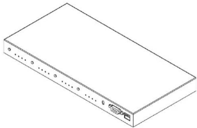
natural_image
Isometric line drawing of a rectangular electronic device with ports and connectors (no text or symbols)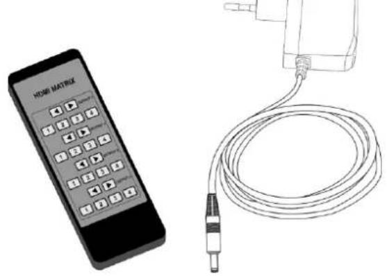
natural_image
Illustration of a home control device and a cable, both without any text or symbols on the devices themselves.Fig. 01
1.2. Intended Use
This device is intended for professional use as an HDMI matrix switch. It is suitable only for indoor installation. This device is not suitable for households.
Any other use, not mentioned under intended use, is regarded as non-intended and incorrect use.
1.3. Product Lifespan
This device is not designed for permanent operation. Disconnect the device from the electrical power supply when the device is not in operation. This will reduce the wear and will improve the device's lifespan.
1.4. Text Conventions
Throughout the user manual the following text conventions are used:
- Buttons: All buttons are in bold lettering, for example "Press the UP/DOWN buttons"
• References: References to chapters and parts of the device are in bold lettering, for example:
"Refer to 2. Safety", "turn the adjustment screw (02)"
• 0–255: Defines a range of values - Notes: Note: (in bold lettering) is followed by useful information or tips
1.5. Symbols and Signal Words
Safety notes and warnings are indicated throughout the user manual by safety signs.
Always follow the instructions provided in this user manual.


DANGER Indicates an imminently hazardous situation which, if not avoided, will result in death or serious injury.
WARNING Indicates a potentially hazardous situation which, if not avoided, could result in death or serious injury.
CAUTION Indicates a potentially hazardous situation, which, if not avoided, may result in minor or moderate injury.
Attention Indicates important information for the correct operation and use of the product.
Important Read and observe the instructions in this document.
Provides important information about the disposal of this product.
1.6. Symbols on the Information Label
This product is provided with an information label. The information label is located on the bottom plate of the device.
The information label contains the following symbols:


This device is designed for indoor use.
This device is IEC protection class III.
This device shall not be treated as household waste.
Read and observe the instructions in this document.
2. Safety

Important Read and follow the instructions in this user manual before installing, operating or servicing this product.
The manufacturer will not accept liability for any resulting damages caused by the non-observance of this manual.
2.1. Warnings and Safety Instructions

DANGER Danger for children
For adult use only. The device must be installed beyond the reach of children.
- Do not leave various parts of the packaging (plastic bags, polystyrene foam, nails, etc.) within children's reach. Packaging material is a potential source of danger for children.

DANGER Incorrect handling of the AC power adapter may result in hazardous situations
This device is delivered with an AC power adapter. Incorrect handling of the AC power adapter may result in hazardous situations.
- Use only the AC power adapter delivered with the device.
- Do not wrap the power cable around the power adapter or any other object. This can damage the internal wires.
- Do not cover the power adapter with anything when it is plugged into the socket-outlet. This may cause overheating.
- Do not expose the power adapter to water or other liquids.
Do not use the power adapter:
• If it shows signs of overheating, for example the plastic is damaged.
- If the AC input pins show signs of corrosion or overheating.
- If the power cable is damaged or shows signs of material fatigue.

Attention General safety
- Do not insert objects into the air vents.
- Do not switch the device on and off in short intervals. This decreases the device's life.
- Do not shake the device. Avoid brute force when installing or operating the device.
- If the device is dropped or struck, disconnect the device from the electrical power supply immediately.
- If the device is exposed to extreme temperature variations (e.g. after transportation), do not switch it on immediately. Let the device reach room temperature before switching it on, otherwise it may be damaged by the formed condensation.

Attention This device shall be used only for the purposes it is designed for.
This device is designed to be used as a professional laser projector. Any incorrect use may lead to hazardous situations and result in injuries and material damage.
- This device is not designed for permanent operation.
- This device does not contain user-serviceable parts. Unauthorized modifications to the device will render the warranty void. Such modifications may result in injuries and material damage.

Attention Do not expose the device to conditions that exceed the rated IP class conditions.
This device is IP20 rated. IP (Ingress Protection) 20 class provides protection against solid objects greater than 12 mm, such as fingers, and no protection against harmful ingress of water.
2.2. Requirements for the User
This product may be used by ordinary persons. Maintenance and installation may be carried by ordinary persons. Service shall be carried out only by instructed or skilled persons. Contact your Highlite International dealer for more information.
Instructed persons have been instructed and trained by a skilled person, or are supervised by a skilled person, for specific tasks and work activities associated with the operation, installation, service and maintenance of this product, so that they can identify risks and take precautions to avoid them.
Skilled persons have training or experience, which enables them to recognize risks and to avoid hazards associated with the operation, installation, service and maintenance of this product.
Ordinary persons are all persons other than instructed persons and skilled persons. Ordinary persons include not only users of the product but also any other persons that may have access to the device or who may be in the vicinity of the device
3. Description of the Device
The DMT VT101 - HDMI Matrix Switcher 4x4 is a combination of a switch and a splitter, allowing the connection of multiple HDMI devices to multiple displays / televisions et cetera. It can be controlled manually or by using an included remote, making operation very easy. An HDMI switch or splitter could never give the same functionality or flexibility. The DMT VT101 supports resolutions up to 3840 x 2160 p @ 60 Hz. Indicators at the front of the unit display the current routing status for a clear overview of your output signals.
3.1. Front View
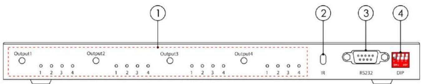
Fig. 02
01) Output 1-4
02) Infrared sensor for remote control
03) RS232 Port
04) Dipswitches #1-#4 (ON=down, OFF=up)
3.2. Back View
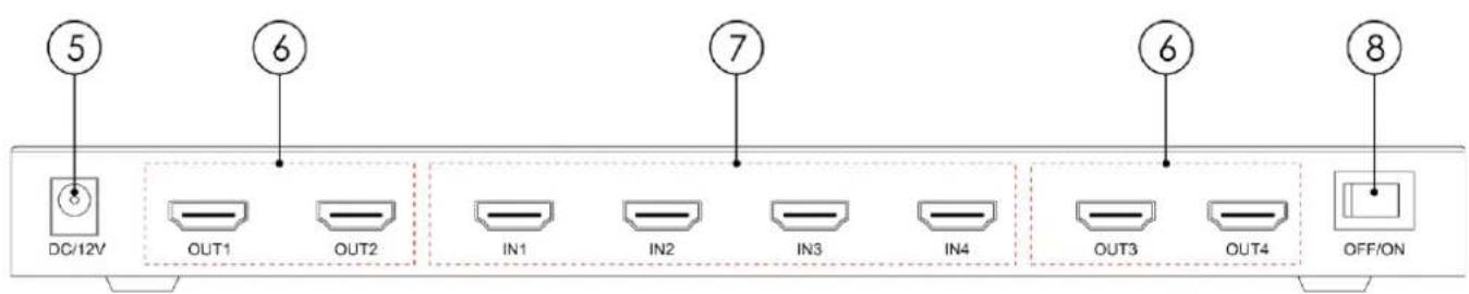
Fig. 03
3.3. Product Specifications
| Model: | VT101 - HDMI Matrix Switcher 4x4 |
| Electrical: | |
| Input voltage: | 100–240 V AC, 50/60 Hz |
| Power consumption: | 15 W |
| Power supply | 12V DC / 2A |
| Physical: | |
| Dimensions: | 276 x 135 x 26 mm (LxWxH) |
| Weight: | 0,735 kg |
| Connections: | |
| Inputs: | RS-2324 HDMI 2.0 (3840 x 2160 p @ 60 Hz) |
| Outputs: | 4 x HDMI 2.0 (2K downscaling) |
| HDMI resolution: | Up to 4K @ 60Hz |
| Construction: | |
| Housing: | Metal |
| Color: | Black |
| IP rating: | IP20 |
| Thermal: | |
| Maximum ambient temperature t_a : | 40 °C |
| Minimum ambient temperature: | -10 °C |
| Maximum housing temperature t_c : | 50 °C |
| Humidity: | 5–90 % |
3.4. Dimensions

Fig. 04
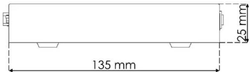
Fig. 05
4. Installation
4.1. Installation Site Requirements
- The device must be installed only indoors.
- The device can be positioned on a flat surface.
- The maximum ambient temperature t_ = 40^ must never be exceeded.
- The relative humidity must not exceed 50% with an ambient temperature of 40 °C.
4.2. Connecting to Power Supply

Attention Incorrect handling of the AC power adapter may result in hazardous situations
This device is delivered with an AC power adapter. Incorrect handling of the AC power adapter may result in hazardous situations.
Connect the device to the socket-outlet with the delivered AC power adapter. Use only the AC power adapter delivered with the device.
5. Setup
5.1. Warnings and Precautions

Attention
Connect all data cables before supplying power.
Disconnect power supply before connecting or disconnecting data cables.
5.2. Setup Example
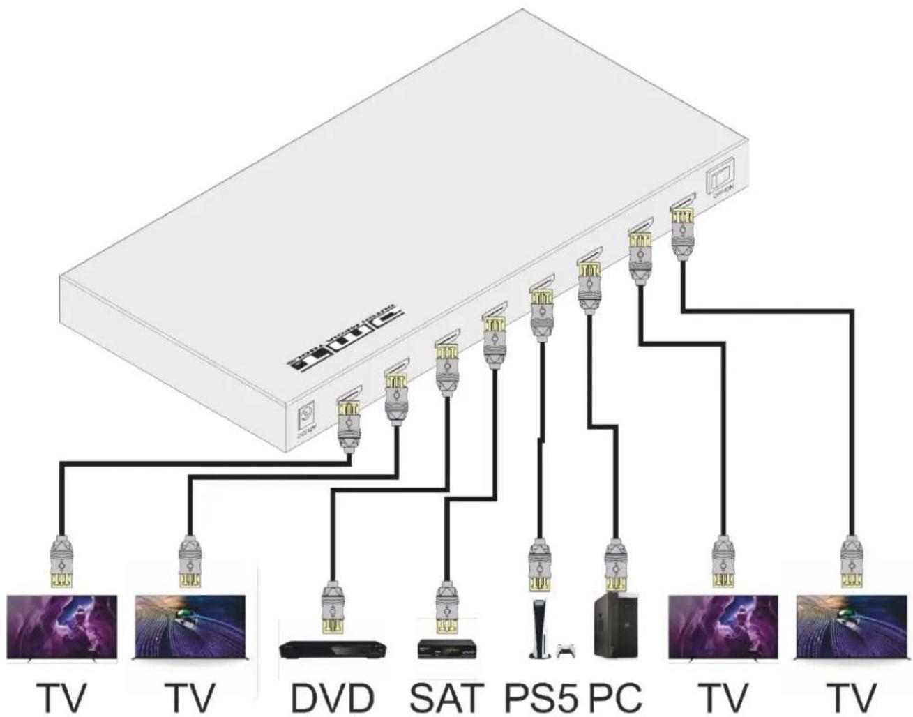
flowchart
graph TD
    A["TV"] --> B["TV"]
    B --> C["DVD"]
    C --> D["SAT"]
    D --> E["PS5 PC"]
    E --> F["TV"]
    F --> G["TV"]
    H["Sat"] --> I["PS5 PC"]
    J["Video"] --> K["TV"]
    L["Video"] --> M["TV"]
Fig. 06
6. Operation
The device can be operated with a remote control or the dipswitches.
Manual operation can be done using:
- the dipswitches, or
• the remote control.
6.1. Safety Instructions for Operation

Attention
This device must be used only for the purposes it is designed for.
This device is intended for professional use as an HDMI matrix switch. It is suitable only for indoor installation. It is suitable only for indoor installation.
Any other use, not mentioned under intended use, is regarded as non-intended and incorrect use.
6.2. Remote Control Operation
The device can be operated with an IR remote control. The remote control is included in the delivery.

DANGER
Do not ingest battery, chemical burn hazard.
The remote control is delivered without batteries. It accepts a CR-2025 coin cell battery. If the coin cell battery is swallowed, it can cause severe internal burns in just 2 hours and can lead to death.
When replacing the battery, make sure that the polarity is correct. Incorrect polarity may damage the remote control.
To operate the device with the IR remote control:
09) Point the remote control to the infrared sensor (02).
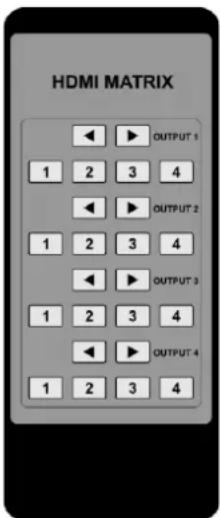
None
Fig. 07 1
To install the batteries:
01) Press on one side of the remote and open the battery housing (Fig. 08).
02) Remove the entire battery holder bracket (Fig. 09).
03) Make sure that you've got the polarity of the battery correctly (Fig. 10).
04) Insert a CR-2025 battery into the battery housing (10) (Fig. 11).
05) Close the battery housing (Fig. 12).
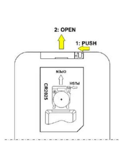
Fig. 08
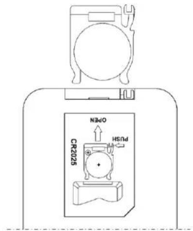
Fig. 09
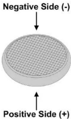
Fig. 10
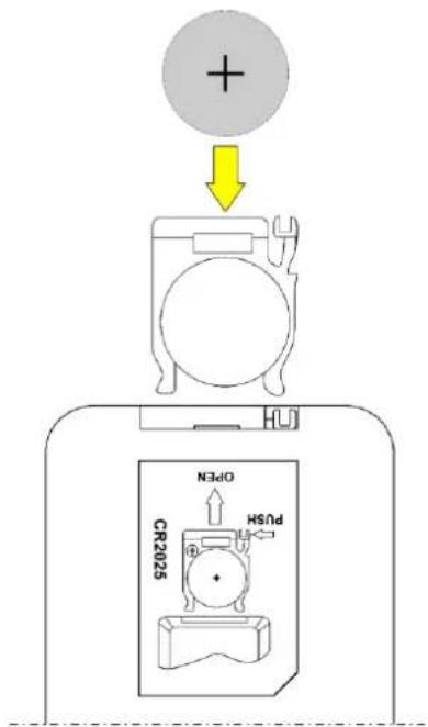
Fig. 11
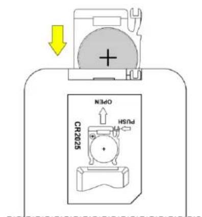
Fig. 12
| Button | Function | Description |
 | Back | Return to the last input port. |
 | Forward | Forward to the next input port. |
 | Input 1 | Press the button to switch to Input 1. |
| [4A0G] | Input 2 | Press the button to switch to Input 2. |
 | Input 3 | Press the button to switch to Input 3. |
 | Input 4 | Press the button to switch to Input 4. |
6.3. Dipswitch Setting
When the dipswitch is set downwards the value is ON, when it is set upwards the value is OFF.
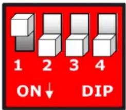
| Dipswitch 1 | Dipswitch 2 | Dipswitch 3 | Dipswitch 4 | Function |
| OFF | OFF | OFF | OFF | 3D 4K 60HZ HDR 2 CH |
| OFF | OFF | OFF | ON | 3D 4K 60HZ 7.1CH |
| OFF | OFF | ON | OFF | 3D 4K 30HZ 2CH |
| OFF | OFF | ON | ON | 3D 4K 30HZ 7.1CH |
| OFF | ON | OFF | OFF | 2D 1080P stereo 2CH |
| OFF | ON | OFF | ON | 2D 1080P 7.1 CH |
| OFF | ON | ON | OFF | 3D 1080P stereo 2CH |
| OFF | ON | ON | ON | 2D 1080P DVI |
6.4. RS232 Control Protocol
| Baud rate | 9600bps |
| Data bits | 8 |
| Parity Check | None |
| Stop bits | 1 |
| Cyclic redundancy check | None |
6.5. RS232 Commands
| Command | HEX | Feedback | Description |
| cir 1e\r\n | 63 69 72 20 31 65 0D 0A | s1x\r\n"x"value range 0~3 | Output 1 select input port No.+1 |
| cir 1d\r\n | 63 69 72 20 31 64 0D 0A | s1x\r\n"x"value range 0~3 | Output 1 select input port No.-1 |
| cir 00\r\n | 63 69 72 20 30 30 0D 0A | s10\r\n | Output 1 select input 1 |
| cir 01\r\n | 63 69 72 20 30 31 0D 0A | s11\r\n | Output 1 select input 2 |
| cir 02\r\n | 63 69 72 20 30 32 0D 0A | s12\r\n | Output 1 select input 3 |
| cir 03\r\n | 63 69 72 20 30 33 0D 0A | s13\r\n | Output 1 select input 4 |
| cir 06\r\n | 63 69 72 20 30 36 0D 0A | s2x\r\n"x"value range 0~3 | Output 2 select input port No.+1 |
| cir 05\r\n | 63 69 72 20 30 35 0D 0A | s2x\r\n"x"value range 0~3 | Output 2 select input port No.-1 |
| cir 08\r\n | 63 69 72 20 30 38 0D 0A | s20\r\n | Output 2 select input 1 |
| cir 09\r\n | 63 69 72 20 30 39 0D 0A | s21\r\n | Output 2 select input 2 |
| cir 0a\r\n | 63 69 72 20 30 61 0D 0A | s22\r\n | Output 2 select input 3 |
| cir 0b\r\n | 63 69 72 20 30 62 0D 0A | s23\r\n | Output 2 select input 4 |
| cir 0e\r\n | 63 69 72 20 30 65 0D 0A | s3x\r\n"x"value range 0~3 | Output 3 select input port No.+1 |
| cir 0d\r\n | 63 69 72 20 30 64 0D 0A | s3x\r\n"x"value range 0~3 | Output 3 select input port No.-1 |
| cir 10\r\n | 63 69 72 20 31 30 0D 0A | s30\r\n | Output 3 select input 1 |
| cir 11\r\n | 63 69 72 20 31 31 0D 0A | s31\r\n | Output 3 select input 2 |
| cir 12\r\n | 63 69 72 20 31 32 0D 0A | s32\r\n | Output 3 select input 3 |
| cir 13\r\n | 63 69 72 20 31 33 0D 0A | s33\r\n | Output 3 select input 4 |
| cir 16\r\n | 63 69 72 20 31 36 0D 0A | s4x\r\n"x"value range 0~3 | Output 4 select input port No.+1 |
| cir 15\r\n | 63 69 72 20 31 35 0D 0A | s4x\r\n"x"value range 0~3 | Output 4 select input port No.-1 |
| cir 18\r\n | 63 69 72 20 31 38 0D 0A | s40\r\n | Output 4 select input 1 |
| cir 19\r\n | 63 69 72 20 31 39 0D 0A | s41\r\n | Output 4 select input 2 |
| cir 1a\r\n | 63 69 72 20 31 61 0D 0A | s42\r\n | Output 4 select input 3 |
| cir 1b\r\n | 63 69 72 20 31 62 0D 0A | s43\r\n | Output 4 select input 4 |
| bc \r\n | 62 63 20 0D 0A | s1x\r\ns2x\r\ns3x\r\ns4x\r\n"x"value range 0~3 | Read HDMI matrix status |
| mrp 0 0\r\n | 6D 72 70 20 30 20 30 0D 0A | mrp 00 00\r\n | Output 1 select IR input 1 |
| mrp 0 1\r\n | 6D 72 70 20 30 20 31 0D 0A | mrp 00 01\r\n | Output 1 select IR input 2 |
| mrp 0 2\r\n | 6D 72 70 20 30 20 32 0D 0A | mrp 00 02\r\n | Output 1 select IR input 3 |
| mrp 0 3\r\n | 6D 72 70 20 30 20 33 0D 0A | mrp 00 03\r\n | Output 1 select IR input 4 |
| mrp 1 0\r\n | 6D 72 70 20 31 20 30 0D 0A | mrp 01 00\r\n | Output 2 select IR input 1 |
| mrp 1 1\r\n | 6D 72 70 20 31 20 31 0D 0A | mrp 01 01\r\n | Output 2 select IR input 2 |
| mrp 1 2\r\n | 6D 72 70 20 31 20 32 0D 0A | mrp 01 02\r\n | Output 2 select IR input 3 |
| mrp 1 3\r\n | 6D 72 70 20 31 20 33 0D 0A | mrp 01 03\r\n | Output 2 select IR input 4 |
| mrp 2 0\r\n | 6D 72 70 20 32 20 30 0D 0A | mrp 02 00\r\n | Output 3 select IR input 1 |
| mrp 2 1\r\n | 6D 72 70 20 32 20 31 0D 0A | mrp 02 01\r\n | Output 3 select IR input 2 |
| mrp 2 2\r\n | 6D 72 70 20 32 20 32 0D 0A | mrp 02 02\r\n | Output 3 select IR input 3 |
| mrp 2 3\r\n | 6D 72 70 20 32 20 33 0D 0A | mrp 02 03\r\n | Output 3 select IR input 4 |
| mrp 3 0\r\n | 6D 72 70 20 33 20 30 0D 0A | mrp 03 00\r\n | Output 4 select IR input 1 |
| mrp 3 1\r\n | 6D 72 70 20 33 20 31 0D 0A | mrp 03 01\r\n | Output 4 select IR input 2 |
| mrp 3 2\r\n | 6D 72 70 20 33 20 32 0D 0A | mrp 03 02\r\n | Output 4 select IR input 3 |
| mrp 3 3\r\n | 6D 72 70 20 33 20 33 0D 0A | mrp 03 03\r\n | Output 4 select IR input 4 |
| mrp 4 0\r\n | 6D 72 70 20 34 20 30 0D 0A | mrp 04 00\r\n | All output select IR input 1 |
| mrp 4 1\r\n | 6D 72 70 20 34 20 31 0D 0A | mrp 04 01\r\n | All output select IR input 2 |
| mrp 4 2\r\n | 6D 72 70 20 34 20 32 0D 0A | mrp 04 02\r\n | All output select IR input 3 |
| mrp 4 3\r\n | 6D 72 70 20 34 20 33 0D 0A | mrp 04 03\r\n | All output select IR input 4 |
7. Troubleshooting
This troubleshooting guide contains actions which can be carried out by the user. The device does not contain user-serviceable parts.
Unauthorized modifications to the device will render the warranty void. Such modifications may result in injuries and material damage.
Refer servicing to instructed or skilled persons. Contact your Highlite International dealer in case the solution is not described in the table.
| Problem | Probable cause(s) | Solution |
| The device does not power up | No power to the device | Check if power is switched on and cables are plugged in |
| The device does not respond to DMX control | The controller is not connected | Connect the controller |
| The device is not in DMX mode | Activate DMX mode from the main menu | |
| The signal is reversed. The 3-pin/5-pin DMX OUT of the controller does not match the DMX IN of the device | Install a phase-reversing cable between the controller and the device | |
| The controller is defective | Try using another controller | |
| The device responds erratically to DMX control | Bad data link connection | Examine connections and cables.Correct poor connections. Repair or replace damaged cables |
| The data link is not terminated with a 120 Ω termination plug | Insert a termination plug in the DMX OUT connector of the last device on the link | |
| Incorrect addressing | Check address settings and correct, if necessary | |
| In case of a setup with multiple devices, one of the devices is defective and disturbs data transmission on the link | To find out which is the defective device, bypass one device at a time until normal operation is restored | |
| The device does not respond to IR remote control | The IR sensor is out of range | Try using the remote control from a different angle. |
| The battery of the remote control is depleted | Change the battery |
8. Maintenance
8.1. Safety Instructions for Maintenance
Maintenance and cleaning shall be carried out only by instructed persons.
Follow the maintenance schedule established for the site where the electrical enclosure is installed.
Disconnect power supply before servicing or cleaning.
8.2. Preventive Maintenance

Attention Before each use, examine the device visually for any defects.
Make sure that:
- All screws used for installing the device or parts of the device are tightly fastened and are not corroded.
• There are no deformations on housings, fixations and installation points. - The power cables are not damaged and do not show any material fatigue.
8.2.1. Basic Cleaning Instructions
To clean the device, follow the steps below:
01) Disconnect the electrical enclosure from the power supply.
02) Clean the device with a soft, lint-free cloth.
03) Remove residual dust with an air-duster or air-blower. Keep the air-duster or air-blower at a minimum distance of 30 cm.

Attention
- Do not immerse the device in liquid.
- Do not use alcohol or solvents.
- Do not clean the device with a brush.
- Make sure that the connections are fully dry before connecting the device to the power supply and to other devices.
8.3. Corrective Maintenance
The device does not contain user-serviceable parts. Do not open the device and do not modify the device.
Refer repairs and servicing to skilled persons. Contact your Highlite International dealer for more information.
9. Deinstallation, Transportation and Storage
- Disconnect power supply before deinstallation.
- Use the original packaging to transport the device, if possible.
- Always observe the handling instructions printed on the outer carton box, for example: "Handle with care", "This side up", "Fragile".
- Clean the device before storing. Follow the cleaning instructions in chapter 8.2.1. Basic Cleaning Instructions on page 16.
- Store the device in the original packaging, if possible.
10. Disposal
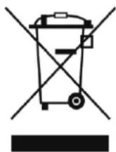
Correct disposal of this product
Disposal of Old Electrical and Electronic Equipment (Applicable in the European Union and other European countries with separate collection systems)
This symbol on the product, its packaging or documents indicates that the product shall not be treated as household waste. Dispose of this product by handing it to the applicable collection point for the recycling of electrical and electronic equipment. This is to avoid environmental damage or personal injury due to uncontrolled waste disposal. For more detailed information about recycling of this product contact the local authorities or the authorized dealer.
11. Approval
CE
UK CA
Check the respective product page on the website of Highlite International (www.highlite.com) for an available declaration of conformity.
- VT101 - HDMI Matrix Switcher 4x4 V1
- Preface
- Table of contents
- Introduction......3
- Safety 5
- Description of the Device....7
- Installation....9
- Setup....10
- Operation....11
- Troubleshooting 15
- Maintenance ....16
- Deinstallation, Transportation and Storage 17
- Disposal....18
- Approval....19
- Introduction
- Before Using the Product
- Intended Use
- Product Lifespan
- Text Conventions
- Symbols and Signal Words
- Symbols on the Information Label
- Safety
- Warnings and Safety Instructions
- Attention General safety
- Attention This device shall be used only for the purposes it is designed for.
- Attention Do not expose the device to conditions that exceed the rated IP class conditions.
- Requirements for the User
- Description of the Device
- Front View
- Back View
- Product Specifications
- Dimensions
- Installation
- Installation Site Requirements
- Connecting to Power Supply
- Setup
- Warnings and Precautions
- Setup Example
- Operation
- Safety Instructions for Operation
- Attention
- Remote Control Operation
- DANGER
- To install the batteries:
- Dipswitch Setting
- RS232 Control Protocol
- Troubleshooting
- Maintenance
- Safety Instructions for Maintenance
- Preventive Maintenance
- Basic Cleaning Instructions
- Corrective Maintenance
- Deinstallation, Transportation and Storage
- Disposal
- Correct disposal of this product
- Approval
Brand : DMT
Model : VT101
Category : Uncategorized