
1264 - Turntable DUAL - Free user manual and instructions
Find the device manual for free 1264 DUAL in PDF.
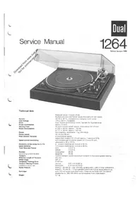


| Brand | Dual |
| Model | 1264 |
| Type | Automatic belt-drive turntable (record changer) |
| Drive | Belt drive with Dual 16-pole synchronous motor |
| Platter | Non-magnetic, detachable, 1 kg, 304 mm diameter |
| Speeds | 33 1/3 and 45 rpm |
| Pitch control | ±3% (approx. 1 semitone) at both speeds |
| Wow & flutter | DIN ±0.07%, WRMS ±0.04% |
| Rumble | Unweighted 48 dB, Weighted 70 dB (DIN 45 500) |
| Tonearm | Tubular aluminium, effective length 221 mm, offset angle 24°, tracking error 0.16°/cm |
| Tonearm bearing | Four-point gimbal with hardened steel points in ball bearings |
| Stylus force range | 0–30 mN (0–3 g), infinitely variable with 1 mN increments |
| Anti-skating | Adjustable via pointer scale on cover |
| Cartridge mount | 1/2 inch standard (requires conversion kit 262 186) |
| Power supply | AC 50/60 Hz, 115 or 230 V (switchable via motor pulley) |
| Power consumption | Approx. 8 W; 75 mA at 220 V 50 Hz, 140 mA at 117 V 60 Hz |
| Starting time | Approx. 2 seconds at 33 1/3 rpm |
| Weight | 4.1 kg |
| Automatic operation | Record changer with multi-play spindle, automatic start/stop and shut-off |
| Stroboscope | Built-in for speed adjustment (50/60 Hz selectable) |
| Muting switch | Short-circuits pickup leads during auto lift/lower to prevent noise |
| Lubrication | After approx. 2 years using specified oils (e.g., Wacker Siliconeoil AK 300,000) |
Frequently Asked Questions - 1264 DUAL
User questions about 1264 DUAL
0 question about this device. Answer the ones you know or ask your own.
Ask a new question about this device
Download the instructions for your Turntable in PDF format for free! Find your manual 1264 - DUAL and take your electronic device back in hand. On this page are published all the documents necessary for the use of your device. 1264 by DUAL.
USER MANUAL 1264 DUAL
Edition January 1980

Technical data
Current
Line Voltage
Drive
Power consumption
Starting Time
Power Consumption
Platter
Platter speeds
Pitch Control Variation
Speed control monitoring
Sensitivity of the strobe for 0.1 % speed deviation
Total Wow and Flutter
Rumble
(according to DIN 45 500)
Tonearm
Effective Length of Tonearm
Offset Angle
Tangential Tracking Error
Tonearm Bearing Friction
(related to stylus tip)
Stylus Pressure
Cartridges
Weight
Measured values = typical values.
Rumble and wow and flutter values obtained with test record.
AC 50 or 60 Hz, changeable by changing motor pulley
115 or 230 V, changeable
Dual 16-pole synchronous motor: flat belt for flywheel drive approx. 8 watts
(to each nominal speed) approx. 2 seconds at 33 1/3 rpm
at 220 V, 50 Hz: approx. 75 mA
at 117 V, 60 Hz: approx. 140 mA
Non-magnetic, detachable, 1 kg, 304 mm φ
33 1/3 and 45 rpm
at both platter speeds
Adjustment range at 33 1/3 rpm approx. 1 semitone (6%)
with stroboscope for platter speeds 33 1/3 and 45 rpm, adjustable to 50 or 60 Hz.
6 division markings per minute at 50 Hz,
7.2 division markings per minute at 60 Hz.
DIN ±0.07%
WRMS ±0.04%
Unweighted 48 dB
Weighted 70 dB
Torsion-resistant tubular aluminium tonearm in four-point gimbal bearing
221 mm
24° 4
0.16°/cm
vertical 0.07 mN (0.007 g)
horizontal 0.15 mN (0.015 g)
from 0 - 30 mN (0 - 3 g) infinitely variable with 1 mN (1/10 g) calibrations
from 0 - 15 mN (0 - 1.5 g) operable from 5 mN (0.5 g) stylus pressure up
with 1/2 inch screw-type attachment. These can be fitted with the special
accessories no. 262 186 which can be obtained from trade dealers.
4.1 kg
Table of Contents
| Page | |
| 1 | Specification |
| 3 | Motor and drive |
| 3 | Speed selection |
| 3 | Turntable |
| 3 | Belt |
| 3 | To replace the motor pulley |
| 4 | Stroboscope |
| 4 | Tuning to the pitch-of-tone level |
| 4 | Tone arm with bearings |
| 4 | To remove tone arm complete with bearings |
| 5 | To remove the tonearm or the spring housing |
| 5 | To adjust the tonearm bearings |
| 5 | Fitting 1/2 inch pick-up |
| 5 | Anti-skating device |
| 5 | Tone arm lift |
| 5 | To replace the lift plate |
| 5 | Tone arm control |
| 6 | The starting sequence |
| 6 | Manual start |
| 6 | Continuous play |
| 6 | Muting switch |
| 6 | Stopping |
| 7 | Shut-off and change cycle |
| 7 | Record drop |
| 7 | Shut-off mechanism |
| 7 | Adjustments |
| 7 | Tone arm set-down point |
| 7 | Set-down point for 30-cm records |
| 7 | Set-down point for 17-cm records |
| 7 | Shut-off point |
| 8 | Tone arm lift height |
| 8 | Tone arm improperly lowered |
| 8 | Rated speed borders pitch adjustment range |
| 8 | Turntable does not start |
| 8-11 | List of spare parts and Exploded view |
| 12 | Lubrication |
Fig. 1 Pick-up Connection Diagram![graph TD A["Kontaktplatte Contact plate Plaque de contacts"] --> B["rot / red / rouge"] A --> C["grün / green / vert"] A --> D["schwarz / black / negro"] A --> E["blau / blue / bleu"] A --> F["weiß / white / blanc"] B --> G["rechter Kanal right channel Canal droit"] C --> G D --> G E --> H["linker K…](/content/2026/05/901131/images/807b3eace19cb4a2341a560079546cc94f3ed8aba85b0d9c73c3ce0c6b5ba1bf.jpg)

Motor and Drive
Turntable and mechanism are driven by the motor 130. This shaded-pole motor runs vibration-free in radially elastic mounts and has extremely low magnetic leakage.
The motor speed is independent of voltage, temperature, and load variation. It can only fluctuate with the mains frequency. Two motor pulleys permit adaptation to the mains frequency of either 50 or 60 Hz; one pulley 116 is shown in both Fig. 2 and Fig. 3.
For 50 Hz use the pulley part no. 261 938,
for 60 Hz use the pulley part no. 261939.
The driving force is transmitted to the turntable 14 by belt 17.
Speed Selection
To adjust the turntable speed to either 33 1/3 or 45 rpm, the belt 17 is shifted to the one step of pulley 116 with the associated diameter (see Fig. 3). This is achieved when you adjust the speed lever 20 so that the START/STOP lever and the spring lever will move the change-over lever into the desired (33 or 45 rpm) position. When the record player is turned off, the changeover lever is blocked by the blocking bar and the speed is just preselected. Only when the turntable 14 starts running, the blocking bar 8 will release the change-over lever. The latter will then shift the belt 17 to that step of motor pulley 116 which corresponds to the desired speed.
Platter
The platter is secured to the securing disc 5 by the bayonet catch. When removing the platter 14 press the securing disc lightly downwards and turn it approximately 60 degrees to the right until it is felt to click out of position.
Belt
To replace the belt 17, first remove the turntable as above described, then separate the belt from the turntable 14. Mount the new belt on the turntable.
NOTE: the ground (mat) surface of the belt should face the driven part. Install the turntable and place the belt 17 over the motor pulley 116.
To Replace the Motor Pulley
- Separate the belt 17 from pulley 116 and remove the turntable. Remove the toothed belt 109.
- Disengage the tension spring 114 from the shield 122.
- Unscrew the hex, nut 111, remove the setting cam 112, belt pulley 113, and counter bearing 114.
- Slacken the grub screws 117 and slide off the motor pulley 116. Slide the replacement pulley onto the motor shaft. Remove the taper sleeve. Pay attention on the internal distance spring. Position the motor pulley 116 at proper height above the mounting plane, see Fig. 3. Uniformly tighten the grub screws 117. Put the taper sleeve into the motor pulley 116.
- Mount the counter bearing 114, the belt pulley 113, and the setting cam 112, and secure them in place with hex nut 111. Install the tension spring 122 and the toothed belt 109. Mount the turntable. Pull the belt 17 and place it around the motor pulley 116.
- Turn the knob 18 to adjust the belt pulley to its mid position. (The nose of the belt pulley 113 should point to the motor pulley center line.) Adjust the hex nut 111 to the rated speed; the speed increases when you turn the nut clockwise and vice versa.


Fig. 4

Fig. 5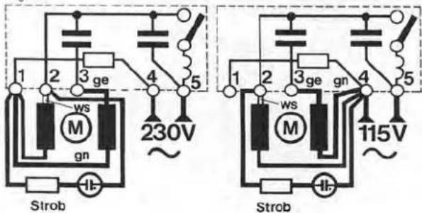
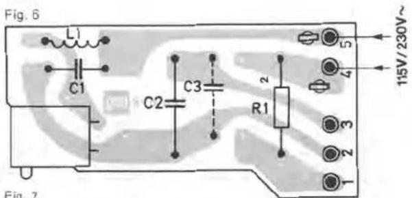


Stroboscope
Even during the play mode, the stroboscope can be used to check the accuracy of the turntable speed adjustment to 33 1/3 and 45 rpm.
Accurate adjustment is manifested by seemingly motionless bar marks of the stroboscope. If the marks run in the same direction as the turntable, the speed is too high and vice versa.
To vary the adjustment, operate the "pitch" knob 18. The strobo marks on the turntable rim have the following meanings (starting from the lowest row): 33 1/3 rpm at 60 Hz, 33 1/3 rpm at 50 Hz. To exchange the glow lamp GI 131, remove the screws 234 and the strobo case.
Pitch Control
This feature is independent of the power and controls both turntable speeds. The tuning range is max. 6% or about one semi-note.
When you rotate the knob 18, you will move the belt pulley 2 105. This motion will be transferred by the toothed belt 109 to the belt pulley 1 113. As a result, the counter bearing 114 and taper sleeve of motor pulley 116 are shifted upwards or downwards, respectively. The taper sleeve of the motor pulley 116 causes the pulley diameter to be reduced or increased, which permits the variation of the rated speed within the said range of ±3%.
Tone Arm with Bearings
The light-weight torsion-resistant aluminum-tube tone arm has a universal gimbal bearing characterized by four hardened and lapped steel points located in high-precision ball bearings. The tone-arm bearing friction is thus reduced to a minimum, namely less than 0.07 mN or 0.007 gr in vertical and less than 0.15 mN or 0.015 gr in horizontal direction,
referred to the stylus point.
This ensures particularly satisfactory tracking conditions. Before adjusting the tracking force, which should comply with the pick-up system used, adjust the tone arm to its balanced position while the tracking-force scale indicates zero.
The tracking force is produced by tensioning the helical spring located in the spring case 62. The rotary turn knob 60 has a scale with marks permitting exact adjustment of the tracking force within the range 0 - 30 mN (or 0 - 3 gr).
To Remove the tonearm complete with the tonearm bearing
We recommend the following procedure:
- Secure the unit in a repair stand. Turn the rotary turn switch 60 to the zero position. Lock the tonearm 38. Remove the counter-weight 55.
- Adjust record player to head position. Remove the shield 160. Unsolder the tone-arm leads from muting switch.
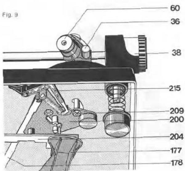
- Remove the main lever 177. Remove the lock washer 242. Rotate the set screw 26 until guide bearing 241 and setting ring bar 228 come free. Remove lock washer 228 and setting bar 204.
- Unlock the tension spring 212, loosen the lock washer 216 and remove skating lever 215.
- Remove lock washer 202 from segment 200.
- Remove hex nuts 209 and the screw 202. Remove the bearing 201 and the segment 200.
- Grip the frame 44 and the tonearm 38. Loosen the machine screw 45 and take off the tonearm and frame.
Reassembly of the tonearm involves the reverse procedure. Take care that the grub screw 43 is correctly seated in the bearing when fastening the frame 44.
To Remove the tonearm or the spring housing
- Secure the unit in a repair stand. Turn the rotary turn switch 60 to the zero position. Lock the tonearm 38. Remove the counterweight 55.
- Turn the unit cover. Remove the screening sheet 160 and solder off the tonearm connections at the muting switch. Turn the unit the right way up.
- Remove the fillister head screw 61. Remove the rotary turn switch 60 and the washer 59.
- Loosen the nut 56 and the grub screw 57. Draw the tone-arm 38 complete with bearing 63 from the bearing race 58. The spring housing 62 or the tonearm 37 may now be changed.
Reassembly involves the reverse procedure.
To Adjust the Tone Arm Bearings
Exactly balance the tone arm. Both bearings should have a small, just perceptible backlash or play. Proper adjustment of the horizontal bearing is achieved if the tone arm can freely slide from the record inside to outside while the anti-skating adjustment is 0.5. Proper adjustment of the vertical bearing is achieved when the carefully kicked tone arm swings into balanced position. Adjust the backlash by grub screws 43 and 57 for the horizontal and vertical bearing, respectively.
Fitting a 1/2 inch cartridge
If a cartridge with 1/2 inch standard mount is to be fitted, the conversion kit Number 262 186 is necessary. The proper method of fitting is shown in fig.
Also the decorative cover should be removed from the counterweight 55 and should be fitted with the compensatory weight to be found in the conversion kit 41.
Coarse adjustment is carried out by moving the weight with stem 38 subsequent fine adjustment by turning the front knurled ring on the weight.
Anti-Skating Device
To adjust the anti-skating force, operate the pointer scale provided on the cover 69. Depending on this adjustment, the skating lever 215 will be deflected from the tonearm pivot point. The anti-skating force is transmitted by the tension spring 212 to the segment 200 and thus to the tonearm 37.
The factory adjustment is optimal for any stylus having a spherical tip radius of 15 μm or elliptical of 5 – 6 and 18 – 22 μm.
These factory-adjusted values may be varied only in an authorized Dual service workshop using a Dual Skate-0-Meter and a test record.
Tone Arm Lift
When you move the lift control bar 218 to the LIFT position ▼, the tone arm will be lifted and in position LOWER ▼ it will be lowered through the lift cam 219 and the setting bar 204. The tone arm lift has priority over the set-down mechanism. When the record player is started with the control bar 218 in the LIFT position ▼, the set-down mechanism will move the tonearm across the record in the auto mode. Lowering of the tonearm will take place only after you have adjusted the control bar 218 to the POWER position ▼.
The height of lift should be 3 to 5 mm; it can be adjusted by the setscrew 26.
To Replace the Lift Plate 158
- Remove the main lever 177 and the lock washer 242. Rotate the setscrew 26 until guide bearing 241 and setting bar 204 are released. Remove lock washer 228 and setting bar 204.
- Unlock the tension spring 212.
- Remove lock washer 206 and disk 205. Detach the shut-off bar 179 from segment 200.
- Remove hex nuts 202 and the screw 202. Remove the segment 200 and the bearing 201.
- Remove the screws 198 and the lift plate 199.
To reassemble, proceed in reversed order.
Fig. 10
Fig. 11
Tone Arm Control
The tonearm motions for auto lowering and lifting are controlled by cams under the cam wheel 161 while the wheel rotates through 360 degrees.
Lifting and lowering motions are controlled by the main lever 177 and lifting bolt while the horizontal motions of the tonearm are controlled by lever 177 with the segment 200.
The lifting/lowering mechanism is active for 30 cm- and 17 cm-records, it is coupled to the turntable-speed change-over function. The tonearm set-down points are determined by the spring pin of segment 200 abutting against the setting bar 204. The horizontal motion is limited by the segment abutting against the setting bar 204 which is lifted only during the set-down operation by the main lever 177 and thus comes into the sluing range of the spring pin provided on the segment.


After the tonearm has been set down on the record, the setting bar 204 is released and returns to its normal position, thus escaping from the range of the spring pin. The tonearm is thus free to move in horizontal direction during the play-back.
The Starting Sequence
When you adjust the START/STOP lever to the START position, the turn-on lever 207 is rotated to the outside and will trigger the following functions:
a) The turn-on lever 207 rotates the shift links 189 seated on the riffled pins 183. At the same time, the power switch is turned on 135 and both the motor 130 and turntable start rotating. b) The shift link 189 enters the range of the reversing lever which is forced into its start position by the subsequent rotation of the cam wheel 161. c) Operation of the START/STOP lever 50 will also release the start angle 187 that is pulled towards the cam wheel by the tension spring 188. The shut-off lever is thus brought into the range of dog M on the turntable pinion (PR) and the cam wheel is driven.
Manual Start
When the tonearm is guided towards the record manually, the pawl 236 coupled to the shift arm 165 will engage with the square bolt mounted in the deck plate and will keep the shift arm in this position. Coupled to the shift arm is the shut-off lever 168 that will turn on the power switch and thus initiate the turntable rotation. When the run-out groove of the record played has been reached, the tonearm is restored and the record player is turned off by automatic means. If you lift the tonearm before the end of play and put it back onto its support, the bolt of segment 200 will release the engaged position of the pawl 236 so that the shift arm is returned to its initial position and the power switch will turn off.
Continuous Play
This mode is operative when you have adjusted the knob 66 to ∞ . The knob 66 will rotate the reversing angle 231 and the latter is forced into the starting position by the turn-on lever 207 at the end of record, the tonearm is restored to its rest position on the support near the record rim. This procedure will be repeated until the START/STOP lever 50 is adjusted to STOP or the knob 66 is adjusted to no. 1 position.
Muting Switch
The muting switch is provided to avoid noisy lifting and lowering of the tonearm in the auto made. The contact springs of both channels are controlled by the cam wheel. The resulting short-circuiting of the pickup leads is ineffective in the rest state of the record player.
Adjustment
In the zero position of the cam wheel, a contact separation of about 0.5 mm should exist between the contact springs (F) and the shorting straps (L) in Fig. 14. If necessary, bend the shorting straps. Maintain contact springs in good state by a spraying agent.
Stopping
When control lever is set to "stop" position the start lever which is pulled towards the cam by means of tension, is free. As a result, the shut-off lever is moved into the range of dogs cam. The guide lever remains in its stop position.
Shut-off and change cycle
Shut-off and change functions are determined by the position of the guide lever U. After every start or record drop, the guide lever is brought to its stop position by the main lever (longer end towards the center of the main cam). As the record is dropped, the guide lever U is turned to its start position by the cam rocker, so that the tonearm can swing in toward the record and be lowered onto it. If there are no more records on the spindle, and the cam rocker cannot turn the guide lever, the lever remains in its stop position and allows the tonearm to swing to its rest position. When the main cam wheel 161 returns to its neutral position, the switch arm 165 drops into a cut-out in the main cam, opening the power switch 135 and disengaging the drive idler.
Record drop
Insert the changing spindle — AW 3 for standard records (7 mm or 1/4" center hole) or AS 12 for 45 rpm records (38 mm or 1 1/2" center hole).
The record drop is initiated by the cam wheel 161 whose drop cam surface AK controls the release rocker AW and the changer actuator rod.
Adjustment
Release rocker
The eccentric screw (c) is used to alter the travel of the changing bolt 168. The setting is correct when at the rest position of the cam wheel 161 and with interlocked changer spindle, the changing bolt 168 has a travel of 0.2 mm.
Shut-off mechanism
The dog M on the turntable platter gear PR and the shut-off lever A actuate both the change cycle at the end of the record as well as the shut-off after the last record in a stack is played. The shut-off bar 179 is guided along in proportion to the movement of the segment 200.
The shut-off procedure is initiated after a record has been played by the dog M of the platter and the shut-off lever A.
The shut-off lever A is moved towards the dog M of the platter within the shut-off range (record diameter 116 mm to 122 mm). The dog engages the shut-off lever A. The cam wheel 16 is moved from 0 position and engages with the drive pinion of the platter.
The main lever 177 guides the tonearm back and effects the tonearm to return to its rest position.
Adjustments
Tone Arm Set-down Point
Slightly pry up the nameplate "Dual" at its lower left corner and swivel it outwards (Fig. 18). The now accessible opening will show one of the adjusting screws.
Set-down Point for 30-cm Records
Adjust the speed selector 20 to the "45" position and correct adjustment with a screwdriver. If the stylus sets down too far on the record inside, rotate the adjusting screw clockwise. If the stylus is lowered outside the 30 cm-record, rotate the screw counter-clockwise.
Set-down Point for 17-cm Records
Adjust the speed selector 20 to the "33" position and rotate the screw as above described for adjustment.
Fig. 15
Fig. 16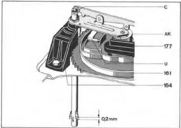
Fig. 17
Shut off Point
In the shutting-off range for records 116 - 122 mm in diameter, the excenter S on segment 200 can be used to vary the shut-off point.
Fig. 18
Fig. 19
Tone Arm Lift Height
This height of the auto mode can be adjusted with the aid of the setting sleeve 197. Pull the mains plug. Disengage the tone arm. Rotate the cam wheel 161 out of its zero position until the tone arm has reached its greatest lift height.
The height above the tone arm support stop should be about 8 mm as shown in Fig. 19. If necessary, rotate the setting sleeve 197 clockwise or anticlockwise as required.
Defect
Tone arm improperly lowered (too fast or not on record).
Cause
Shock-absorbing action of silicone oil in lift tube is excessive or insufficient.
Rated speed borders pitch adjustment range.
Positioning of belt pulley is inaccurate.
Turntable does not start.
a) Belt is not in place. b) Motor is not powered. c) Motor pulley has come loose.
Repair
Demount the lift plate 199, remove the control stud 195, lock washer 196, and setting sleeve 197 with lock washer; remove lift bolt and pressure spring, clean lift tube and lift bolt. Evenly apply WACKER SILICONE OIL AK 500 000 to the lift bolt. Reassemble the parts.
Adjust knob 18 to mid position; adjust hex, nut 111 to rated speed (clockwise adjustment will increase the speed and vice versa).
a) Mount the belt. b) Check switch base and mains plug. c) Tighten it.
Replacement parts
| Pos. | Part.-No. | Qty | Description |
| 1 | 215 470 | 1 | Automatic Spindle |
| 2 | 213 895 | 1 | Change spindle |
| 3 | 220 213 | 1 | Centering piece |
| 4 | 261 910 | 1 | Idling pin |
| 5 | 263 395 | 1 | Lock washer complete |
| 6 | 261 914 | 1 | Mount complete |
| 7 | 248 346 | 1 | Pressure spring |
| 8 | 261 916 | 1 | Locking rail compl. |
| 8 | 264 027 | 1 | Locking rail compl. |
| 9 | 249 171 | 1 | Tension spring |
| 10 | 248 347 | 1 | Tension spring |
| 11 | 260 157 | 1 | Stop |
| 12 | 263 950 | 1 | Platter mat |
| 13 | 248 893 | 1 | Spring washer |
| 14 | 263 951 | 1 | Platter complete |
| 15 | 200 543 | 1 | Snap spring |
| 16 | 263 399 | 1 | Fly wheel rotor complete |
| 17 | 261 921 | 1 | Flat belt |
| 18 | 260 461 | 1 | Regulating knob |
| 19 | 232 078 | 1 | Bearing bush |
| 20 | 260 297 | 1 | Speed lever |
| 21 | 263 378 | 1 | Speed cover |
| 22 | 213 260 | 4 | Grooved drive stud |
| 23 | 210 194 | 1 | Grip ring |
| 24 | 210 472 | 1 | Machine screw |
| 25 | 234 599 | 1 | Reset cam |
| 26 | 240 069 | 1 | Adjusting screw |
| 27 | 263 400 | 1 | Mounting plate complete |
| 30 | 237 228 | 2 | Spring suspension |
| 234 433 | 2 | Spring suspension (motor side) | |
| 31 | 230 529 | 1 | Threaded coupling |
| 32 | 236 712 | 2 | Pressure spring |
| 232 843 | 2 | Pressure spring (motor side) | |
| 33 | 200 723 | 4 | Rubber absorber |
| Pos. | Part.-No. | Qty | Description |
| 34 | 200 722 | 4 | Casing |
| 35 | 239 414 | 3 | Transport lock |
| 36 | 260 428 | 1 | Clamping |
| 37 | 263 262 | 1 | Tonearm complete |
| 38 | 263 401 | 1 | Weight complete |
| 263 983 | 1 | Weight complete (UAP) | |
| 39 | 263 259 | 1 | Tonearm head complete |
| 40 | 261 929 | 1 | Tonearm lead |
| 41 | 262 186 | 1 | 1/2 inch conversion kit complete |
| 42 | 249 383 | 1 | Counter nut |
| 43 | 234 651 | 1 | Grub screw |
| 44 | 261 979 | 1 | Frame complete |
| 45 | 242 677 | 1 | Machine screw M 4 x 8 |
| 48 | 236 069 | 1 | Machine screw |
| 49 | 248 979 | 1 | Lifting plate |
| 50 | 260 298 | 1 | Switch lever |
| 51 | 260 328 | 1 | Stroboscope prism |
| 52 | 263 408 | 1 | Tonearm rest complete |
| 56 | 246 884 | 1 | Conter nut |
| 57 | 234 634 | 1 | Grub screw |
| 58 | 261 981 | 1 | Bearing race complete |
| 59 | 261 798 | 1 | Washer 5,2/10 |
| 60 | 248 989 | 1 | Rotary knob |
| 61 | 249 097 | 1 | Raised countersunk head screw M 2,5 x 12 |
| 62 | 263 331 | 1 | Spring housing complete |
| 63 | 263 330 | 1 | Bearing complete |
| 64 | 210 597 | 1 | Washer |
| 65 | 262 294 | 1 | Screw |
| 66 | 260 334 | 1 | Rotary knob |
| 67 | 263 407 | 1 | Rear cover |
| 68 | 200 444 | 7 | Spring washer |
| 69 | 260 320 | 1 | Cam disc |
| 70 | 242 298 | 1 | Washer |
Fig. 20 Exploded view 1
Fig. 21 Exploded view 2
| Pos. | Part.-No. | Qty | Description |
| 71 | 228 113 | 1 | Washer 4,2/8/1 |
| 72 | 210 146 | 1 | Lock washer 3,2 |
| 73 | 263 953 | 1 | Font cover complete |
| 100 | 260 537 | 1 | Connection part |
| 101 | 232 079 | 1 | Shouldered nut |
| 102 | 232 097 | 1 | Belt wheel |
| 103 | 240 035 | 1 | Washer |
| 104 | 210 607 | 1 | Washer 3,2/10/0,5 |
| 105 | 210 362 | 1 | Hex nut M 3 |
| 106 | 260 570 | 1 | Clip spring |
| 107 | 210 196 | 1 | Grip ring |
| 108 | 260 475 | 1 | Switch lever |
| 109 | 260 309 | 1 | Toot hed belt |
| 110 | 210 607 | 3 | Washer 3,2/10/0,5 |
| 111 | 244 104 | 1 | Hex nut |
| 112 | 241 641 | 1 | Control curve |
| 113 | 241 642 | 1 | Belt wheel 1 |
| 114 | 248 508 | 1 | Conter bearing |
| 115 | 232 615 | 1 | Presure spring |
| 116 | 261 938 | 1 | Motor pulley 50 Hz |
| 261 939 | 1 | Motor pulley 60 Hz | |
| 117 | 233 137 | 1 | Grub screw |
| 118 | 247 920 | 1 | Earth bracket |
| 119 | 210 145 | 3 | Lock washer |
| 120 | 210 609 | 3 | Washer |
| 121 | 249 182 | 3 | Damping sleeve |
| 122 | 233 777 | 1 | Tension spring |
| 123 | 261 121 | 1 | Motor plate |
| 124 | 248 335 | 2 | Machine screw |
| 125 | 261 944 | 1 | Stator 110/200 V kpl. |
| 261 946 | 1 | Stator 110/220 V kpl. UI/CSA | |
| 126 | 261 945 | 1 | Armature with bearing complete |
| 127 | 222 200 | 2 | Hex nut M 3,5 |
| 128 | 209 939 | 1 | Rubber bush |
| 129 | 247 858 | 1 | Screening plate |
| 130 | 261 961 | 1 | Motor SM 100-1 compl. |
| 131 | 260 421 | 1 | Glow lamp |
| 132 | 249 092 | 1 | Switch plate |
| 133 | 263 336 | 1 | Stroboscope housing complete |
| 134 | 210 469 | 1 | Machine screw |
| 135 | 260 137 | 1 | Housing |
| 136 | 261 965 | 1 | Switch plate |
| 137 | 262 272 | 1 | Power switch |
| C 1 | 241 646 | 1 | 10 nF/250 V/20 % |
| C 2 | 249 352 | 1 | 0.33 μF/250 V/10 % |
| C 3 | 230 355 | 1 | 68 nF/250 V/20 % |
| R 1 | 249 354 | 1 | 5.1 kΩ/5 W/5 % |
| L 1 | 242 822 | 1 | RF cocke 47 μH |
| 138 | 248 881 | 1 | Cover |
| 139 | 210 491 | 1 | Machine screw |
| 157 | 236 402 | 1 | Muting switch |
| 158 | 239 562 | 1 | Soldering lug |
| 159 | 210 472 | 2 | Machine screw |
| 160 | 232 084 | 1 | Screen sheet |
| 161 | 236 912 | 1 | Cam wheel complete |
| 162 | 210 366 | 1 | Hex nut |
| 163 | 218 155 | 2 | Hex screw |
| 164 | 263 955 | 1 | Bearing bridge complete |
| 165 | 234 542 | 1 | Switch arm |
| 166 | 248 878 | 1 | Switch lever |
| 167 | 260 363 | 1 | Tension spring |
| 168 | 260 387 | 1 | Switch off lever |
| 169 | 229 686 | 1 | Tension spring |
| 170 | 210 145 | 1 | Lock washer 2,3 |
| 171 | 234 592 | 1 | Connection rod |
| 172 | 210 587 | 1 | Washer 3,2/7/1 |
| 173 | 234 677 | 1 | Bearing bracket |
| 174 | 210 667 | 1 | Washer 5,3/10/0,5 |
| 175 | 234 676 | 1 | Screw bolt |
| 176 | 210 147 | 1 | Lock washer 4 |
| 177 | 236 914 | 1 | Main lever |
| 178 | 211 718 | 1 | Ball 5 3 |
| 179 | 234 668 | 1 | Stop rail |
| 180 | 234 558 | 2 | Ball bed |
| 181 | 210 472 | 2 | Machine screw M 3 x 4 |
| Pos. | Part.-No. | Qty | Description | |
| 182 | 210 362 | 1 | Hex nut | M 3 |
| 183 | 234 544 | 1 | Groove bolt | |
| 184 | 210 586 | 1 | Washer | 3,2 |
| 185 | 236 950 | 1 | Stop bush | |
| 186 | 239 931 | 1 | Roller | |
| 187 | 234 545 | 1 | Start angle | |
| 188 | 229 698 | 1 | Tension spring | |
| 189 | 244 784 | 1 | Switch crank | |
| 190 | 234 555 | 1 | Switch over lever | |
| 191 | 234 598 | 1 | Connection rod | |
| 192 | 210 146 | 1 | Lock washer | 3,2 |
| 195 | 216 844 | 1 | Control nipple stud | |
| 196 | 210 143 | 3 | Lock washer | 1,5 |
| 197 | 218 318 | 1 | Adjustable adapter | |
| 198 | 210 472 | 2 | Machine screw | M 3 x 4 |
| 199 | 263 402 | 1 | Lift plate complete | |
| 200 | 263 403 | 1 | Segment | |
| 201 | 242 615 | 1 | Counter bearing | |
| 202 | 203 475 | 1 | Counter sunk screw | M 3 x 8 |
| 203 | 223 777 | 1 | Control nipple stud | |
| 204 | 240 060 | 1 | Slide rail | |
| 205 | 201 187 | 1 | Sliding washer | |
| 206 | 210 145 | 4 | Loch washer | 2,3 |
| 207 | 244 709 | 1 | Switch on lever | |
| 208 | 210 641 | 1 | Washer | 4,2/10/1 |
| 209 | 210 362 | 1 | Hex nut | M 3 |
| 210 | 234 548 | 1 | Roller | |
| 211 | 210 143 | 3 | Lock washer | 1,5 |
| 212 | 218 591 | 1 | Tension spring | |
| 213 | 201 184 | 1 | Adjusting washer | |
| 214 | 242 298 | 1 | Washer | |
| 215 | 244 331 | 1 | Skating lever | |
| 216 | 210 146 | 1 | Lock washer | 3,2 |
| 217 | 237 543 | 1 | Rubber bush | |
| 218 | 237 541 | 1 | Grip rod complete | |
| 219 | 240 063 | 1 | Lifting piece | |
| 220 | 210-353 | 1 | Hex nut | |
| 221 | 240 066 | 1 | Bearing plate | |
| 222 | 210 469 | 1 | Machine screw | |
| 223 | 234 674 | 1 | Brahing piece | |
| 224 | 210 587 | 1 | Washer | |
| 225 | 234 588 | 1 | Adjusting lever | |
| 226 | 230 087 | 1 | Screw bolt | |
| 227 | 210 146 | 3 | Lock washer | 3,2 |
| 228 | 210 145 | 4 | Lock washer | 2,3 |
| 229 | 210 586 | 1 | Washer | |
| 230 | 232 545 | 1 | Leaf spring | |
| 231 | 234 593 | 1 | Reversing angle | |
| 232 | 203 477 | 1 | Washer | |
| 233 | 210 353 | 1 | Hex nut | |
| 234 | 232 599 | 1 | Latch | |
| 235 | 210 146 | 3 | Lock washer | |
| 236 | 239 915 | 1 | Square plate | |
| 237 | 210 472 | 1 | Machine screw | |
| 238 | 210 586 | 1 | Washer | |
| 239 | 245 247 | 1 | Screw bolt | |
| 240 | 239 810 | 1 | Locking spring | |
| 241 | 229 362 | 1 | Guide bearing | |
| 242 | 210 145 | 4 | Lock washer | 2,3 |
| 249 | 209 436 | 3 | Tab receptable | |
| 250 | 209 424 | 1 | 5-pole plug | |
| 251 | 207 303 | 1 | Phono pick up cable complete | |
| 252 | 207 301 | 1 | Phono pick up cable (cynch) | |
| 253 | 209 425 | 1 | Cynch plug white | |
| 254 | 209 426 | 1 | Cynch plug black | |
| 255 | 214 602 | 2 | AMP-receptable | |
| 256 | 232 996 | 1 | Mains lead Europe | |
| 257 | 232 995 | 1 | Mains lead USA | |
| 258 | 231 079 | 1 | Cable clamp | |
| 261 952 | 1 | CK 28 walnut console | ||
| 261 953 | 1 | CK 28 agale black console | ||
| 261 954 | 1 | CK 28 agale brown console | ||
| 227 986 | 1 | CH 6 cover | ||
| 261 600 | 1 | Operating instructions | ||
| 262 016 | 1 | Operating instructions UAP | ||
| 260 491 | 1 | Shipping carton CS | ||
Subject to change!
Lubrication
All bearing and friction points of the unit are adequately lubricated at the works. Replenishment of oil and grease is only necessary after approximately 2 years of normal use of the record player as the most important bearing points (motor bearings) have sintered metal bushes.
Bearing points and friction faces should be lubricated sparingly rather than generously.
It is important that no oil or grease should come in contact with the friction faces of the flat belt, drive pulley and flywheel rotor, otherwise slip will occur.
When using different lubricants, chemical decomposition can often take place. To prevent lubrication failure we recommend using the original lubricants stated below.
Fig. 22
Fig. 23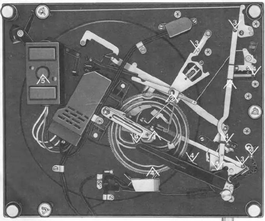
1
Wacker Siliconeoil AK 300 000
2
Renotac adhesive oil No. 343
3
BP Super Viscostatic 10 W/40
4
Shell Alvania No. 2
5
Isoflex PDP 40



- TECHNICAL DATA
- MOTOR AND DRIVE
- SPEED SELECTION
- PLATTER
- BELT
- TO REPLACE THE MOTOR PULLEY
- STROBOSCOPE
- PITCH CONTROL
- TONE ARM WITH BEARINGS
- TO REMOVE THE TONEARM COMPLETE WITH THE TONEARM BEARING
- TO REMOVE THE TONEARM OR THE SPRING HOUSING
- TO ADJUST THE TONE ARM BEARINGS
- FITTING A 1/2 INCH CARTRIDGE
- ANTI-SKATING DEVICE
- TONE ARM LIFT
- TO REPLACE THE LIFT PLATE
- TONE ARM CONTROL
- THE STARTING SEQUENCE
- MANUAL START
- CONTINUOUS PLAY
- MUTING SWITCH
- ADJUSTMENT
- STOPPING
- SHUT-OFF AND CHANGE CYCLE
- RECORD DROP
- RELEASE ROCKER
- SHUT-OFF MECHANISM
- ADJUSTMENTS
- TONE ARM SET-DOWN POINT
- SET-DOWN POINT FOR 30-CM RECORDS
- SET-DOWN POINT FOR 17-CM RECORDS
- SHUT OFF POINT
- TONE ARM LIFT HEIGHT
- DEFECT
- CAUSE
- REPAIR
- LUBRICATION
Brand : DUAL
Model : 1264
Category : Turntable