IPOE-176S - Separator Planet - Free user manual and instructions
Find the device manual for free IPOE-176S Planet in PDF.


| Product Type | PoE Splitter |
| Dimensions | 80 x 54 x 30 mm |
| Weight | 50 g |
| Power Input | 48 V DC (PoE) |
| Power Output | 12 V DC, 1 A |
| Data Rate | 10/100 Mbps |
| Connector Type | RJ-45 (input), RJ-45 + DC jack (output) |
| Compliance | IEEE 802.3af, CE, RoHS |
| Main Functions | Splits PoE power and data; plug-and-play; surge protection |
| Maintenance & Cleaning | Wipe with dry cloth; do not use liquids or solvents |
| Safety | Overcurrent and short circuit protection |
| Spare Parts & Repairability | No user-serviceable parts; contact Planet support for replacement |
| General Information | Operating temperature: 0°C to 40°C; humidity: 10% to 90% non-condensing |
Frequently Asked Questions - IPOE-176S Planet
User questions about IPOE-176S Planet
0 question about this device. Answer the ones you know or ask your own.
Ask a new question about this device
Download the instructions for your Separator in PDF format for free! Find your manual IPOE-176S - Planet and take your electronic device back in hand. On this page are published all the documents necessary for the use of your device. IPOE-176S by Planet.
USER MANUAL IPOE-176S Planet
Industrial Single-Port 802.3bt PoE++ Splitter
IPOE-17xS Series
User's Manual
Table of Contents
- Package Contents....3
- Product Specifications....4
- Hardware Introduction....7
3.1 Front Panel and LED Indicators 7
3.2 4-pin Power Output Terminal Block....8
3.3 DC Voltage DIP Switch 9
3.4 Grounding the Device.... 10 - Installation 11
- Three-View Diagram 13
Customer Support.... 15
1. Package Contents
Thank you for purchasing PLANET Industrial 802.3bt PoE++ Splitter, IPOE-17xS Series. "PoE Splitter" mentioned in this manual refers to the IPOE-17xS Series. The description of this series is shown below:
| IPOE-173S Industrial Single-Port 10/100/1000Mbps 802.3bt PoE++ Splitter |
| IPOE-176S Industrial Single-Port 10Gbps 802.3bt PoE++ Splitter |
Open the box of the Industrial 802.3bt PoE++ Splitter and carefully unpack it. The box should contain the following items:
| Industrial PoE++ Splitter x 1 Quick Start QR Code Sheet x 1 | ||
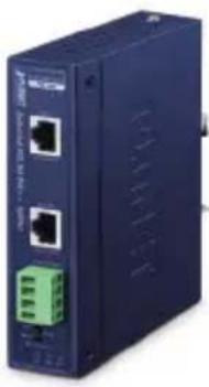 |  | |
| DIN-rail Kit x 1 RJ45 Dust Caps x 2 Wall-mount Kit x 1 | ||
 | 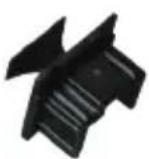 |  |
If any of these are missing or damaged, please contact your dealer immediately.
2. Product Specifications
| Product IPOE-173S IPOE-176S | |||
| HW Version 2.0 1.0 | |||
| Hardware Specifications | |||
| Interface | PoE Input Port | 1 10/100/1000BASE-T RJ45 | 1 10M/100M/1G/2.5G/5G/10G BASE-T RJ45 |
| Data Output Port | 1 10/100/1000BASE-T RJ45 | 1 10M/100M/1G/2.5G/5G/10G BASE-T RJ45 | |
| DC Out Plug Connector | 1 removable 4-pin terminal block | ||
| DIP Switch 12V/19V/24V DC output | |||
| LED Indicators | PoE Input:30W (Green)60W (Green)90W (Green)DC Voltage:12V (Green)19V (Green)24V (Green) | ||
| Data Rate 10/100/1000Mbps 10M/100M/1G/2.5G/5G/10Gbps | |||
| Dimensions (W x D x H) | 32 x 87 x 135 mm | ||
| Weight 440g 433g | |||
| Installation DIN-rail/wall mountable | |||
| ESD Protection 4KV | |||
| EFT Protection 4KV | |||
| Enclosure IP30 metal case | |||
| Power Requirements | 4-pair 802.3at PoE+ and 802.3bt PoE++PoE DC 48 ~ 54V | ||
| Power Consumption | System on with PoE input | 12V DC: 5.3 watts19V DC: 6.6 watts24V DC: 8.2 watts | 12V DC: 5.5 watts19V DC: 6.8 watts24V DC: 7.6 watts |
| Full loading with maximum 12V DC, 6.8A output | 12V DC: 98.3 watts19V DC: 98.5 watts24V DC: 97.9 watts | ||
| Power Output | 802.3 bt type 4 PoE++ input | 12V DC, 6.8A (max.)19V DC, 4.3A (max.)24V DC, 3.3A (max.) | |
| Network Cable | 802.3 bt PoE++ input (60W+) | 4-pair UTP Cat. 5e, 6, up to 100m (328ft) | Twisted-pair cable up to 100 meters (328ft)10BASE-T:4-pair UTP Cat. 3, 4, 5, 5e, 6, 6A100BASE-TX: 4-pair UTP Cat. 5, 5e, 6, 6A1G/2.5G:4-pair UTP Cat 5e/Cat 6/Cat 6A/ Cat 75G:4-pair UTP Cat 6/Cat 6A/Cat 710G:4-pair UTP Cat 6A/Cat 7 |
| 802.3at PoE+ input (30W) | 2-pair UTP Cat. 5, 5e, 6, up to 100m (328ft) | ||
| Power over Ethernet | |||
| PoE Standard | 802.3 bt PoE++4-pair 802.3at PoE+ | ||
| Power Output DC 12V/19V/24V by DIP switch control | |||
| PoE Power Supply Type | End-span + Mid-spanEnd-spanMid-span | ||
| Power Pin Assignment | 1/2 (+), 3/6 (-); 4/5 (+), 7/8 (-) or1/2 (-), 3/6 (+); 4/5 (+), 7/8 (-) | ||
| Remote Power Distance NA | 1G/2.5G speed: 100M (max.)5G/10G speed: 80M (max.)(cat6A/cat7) | |
| Standards Conformance | ||
| Standards Compliance | IEEE 802.3 10BASE-T EthernetIEEE 802.3u100BASE-TX Fast EthernetIEEE 802.3ab1000BASE-T Gigabit EthernetIEEE 802.3at Power over Ethernet PlusIEEE 802.3bt 4-pair Power over Ethernet Type 4 | IEEE 802.3 10BASE-T EthernetIEEE 802.3u 100BASE-TX Fast EthernetIEEE 802.3ab 1000BASE-T Gigabit EthernetIEEE 802.3bz2.5G/5G/10GBASE-T IEEE 802.3af Power over EthernetIEEE 802.3at Power over Ethernet PlusIEEE 802.3bt 4-pair Power over Ethernet Type 4 |
| Regulatory Compliance FCC Part 15 Class A, CE | ||
| Environment | ||
| Operating Temperature -40 ~ 75 degrees C | ||
| Storage Temperature -40 ~ 85 degrees C | ||
| Humidity 5 ~ 95% (non-condensing) | ||
3. Hardware Introduction
3.1 Front Panel and LED Indicators
IPOE-173S IPOE-176S
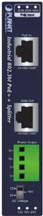

Figure 3-1: Front Panel of IPOE-17xS Series
■ PoE input indicators
| LED Color Function | |
| 30W Green | Lights to indicate the PoE Splitter is working in 802.3at PoE mode. |
| 60W Green | Lights to indicate the PoE Splitter is working in 802.3bt type 3 PoE mode. |
| 90W Green | Lights to indicate the PoE Splitter is working in 802.3bt type 4 PoE mode. |
■ DC output voltage indicators
| LED Color Function | |
| 12V Green | Lights to indicate the PoE Splitter's output is in 12V DC mode. |
| 19V Green | Lights to indicate the PoE Splitter's output is in 19V DC mode. |
| 24V Green | Lights to indicate the PoE Splitter's output is in 24V DC mode. |
3.2 4-pin Power Output Terminal Block
If there is no power socket in your network environment, PLANET IPOE-17xS Series provides DC power for this Ethernet device conveniently. The IPOE-17xS Series splits the transmission of the power and data.
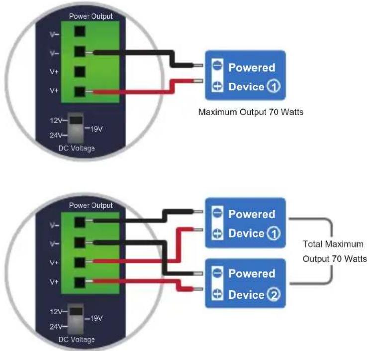
From top to down, there are Negative (V-), Negative (V-), Positive (V+) and Positive (V+), and two sets of DC power output contact.
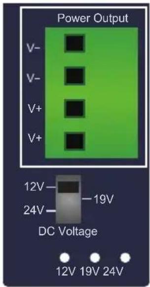
Figure 3-2: Terminal Block of IPOE-17xS Series *IPOE-176S_PS.png

It comes with three DC outputs -- 12V, 6.8A, 19V, 4.3A or 24V, 3.3A, totaling 70 watts of DC output power, which means that DC1 + DC2 cannot be over the 70-watt DC output power limit. Otherwise, it might cause the power output to malfunction or damage.
3.3 DC Voltage DIP Switch
It provides three kinds of DC power output through its DIP switch and its voltage and current are shown below:
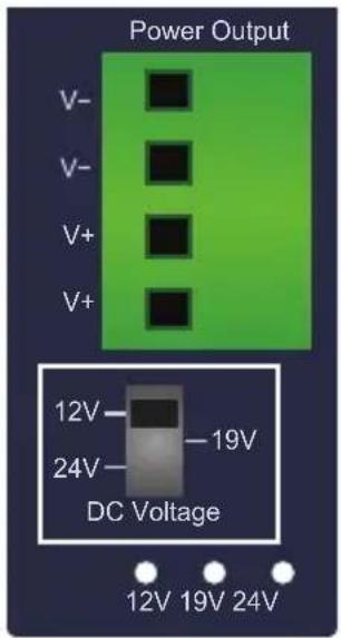
Figure 3-3: DIP Switch of IPOE-17xS Series
| Caution | Please check the power requirements of the device carefully that is going to get the power from the IPOE-17xS Series.If the power requirement is higher than the IPOE-17xS Series that can supply, current overload might shut down the IPOE-17xS Series itself. Thus, it will also shut down your device as well.Please ensure the output voltage is correct for remote device. Otherwise, it will damage your remote device. |
| Caution | Do not switch on/off the Power DIP during operation. Otherwise, it will damage your IPOE-17xS Series and remote device. If you want to switch from one output voltage to another via DIP switch, plug out the “PoE In” cable and wait for 3 seconds until the PoE Input LEDs are completely OFF. |
3.4 Grounding the Device
Users MUST complete grounding wired with the device; otherwise, a sudden lightning could cause fatal damage to the device.
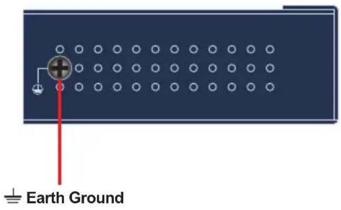

EMD (Lightning) DAMAGE IS NOT COVERED UNDER WARRANTY.
4. Installation
Wiring the Power Outputs
Please follow the steps below to insert the power wires.
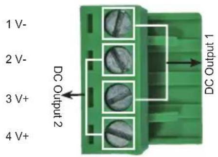
Step 1: Please find one terminal block connector within two DC pow outputs shown below:

Note
The wire gauge for the terminal block should be in the range of 12 \~ 24 AWG.
Step 2: Insert the Negative/Positive DC wires into the V- / V+ terminal; Terminals 1 and 3 for Power 1; Terminals 2 and 4 for Power 2.
Step 3: Connect the other end of DC power wires to the power devices. Tighten the wire-clamp screws for preventing the wires from loosening.
Step 4: Install the terminal block on PLANET IPOE-17xS Series Splitter.
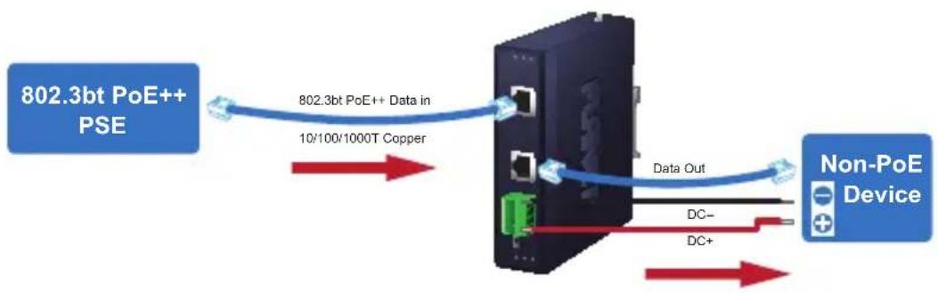
Step 5: Connect the network copper cable (RJ45) from an 802.3bt PoE++ PSE to the IPOE-17xS Series Splitter where the power and data are separately transmitted to a PD as shown in the figure below following figure is based on the IPOE-173S. The display of the IPOE-17xS Series is the same):
flowchart
graph LR
    A["802.3b PoE++ PSE"] -->|Data in 10/100/1000T Copper| B["Device"]
    B -->|Data Out| C["Non-PoE Device"]
    B -->|DC-| D["Ground"]
    B -->|DC+| E["Ground"]

Make sure the IPOE-17xS Series' output voltage (DC 12V/19V/24V) is correct before applying power to a remote device.
5. Three-View Diagram
IPOE-173S
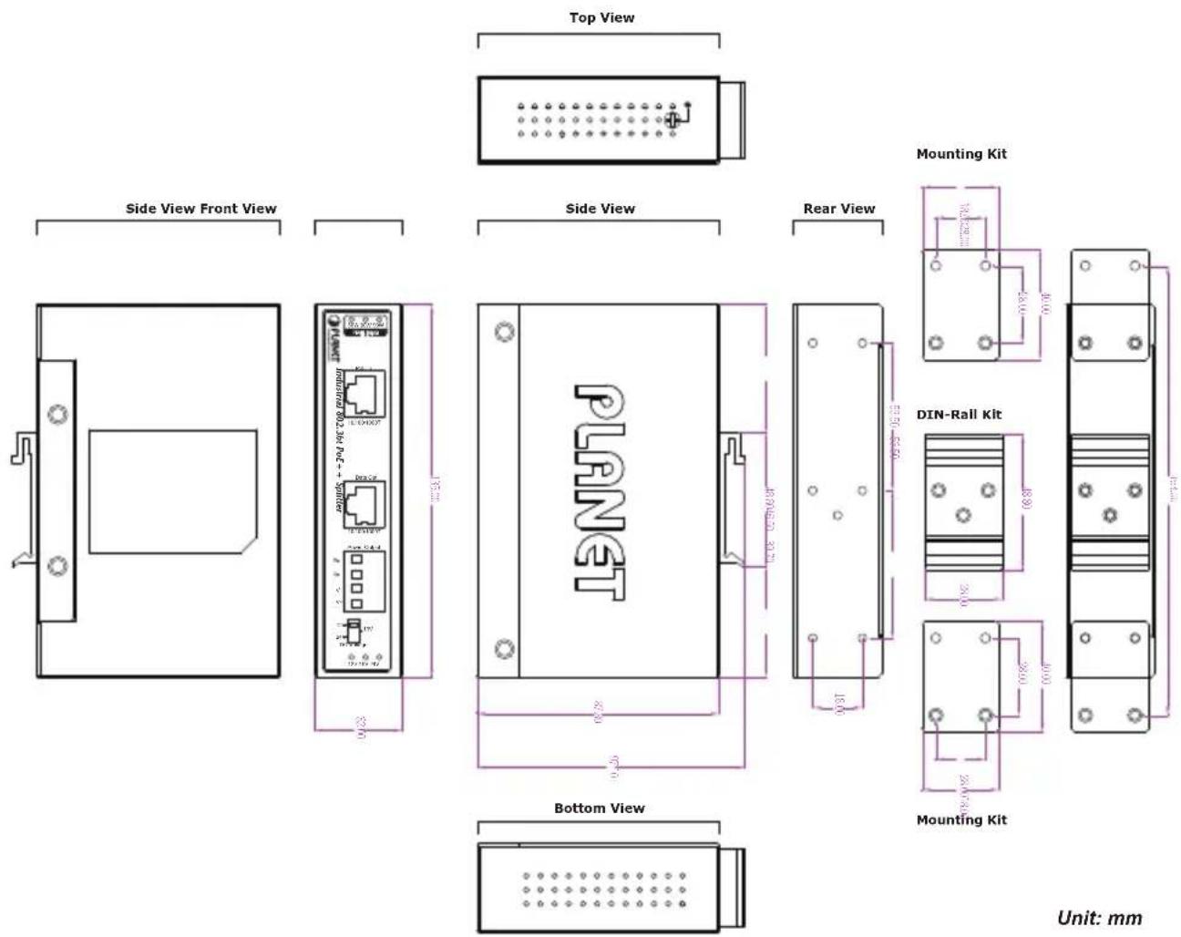
Figure 5-1: IPOE-173S Three-View Diagram
IPOE-176S
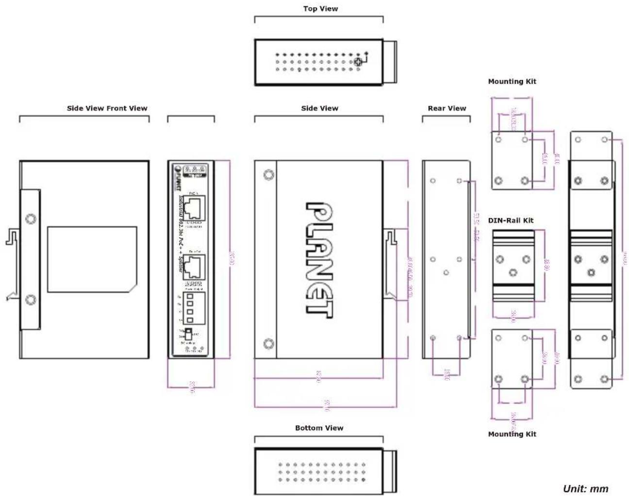
Figure 5-2: IPOE-176S Three-View Diagram
Customer Support
Thank you for purchasing PLANET products. You can browse our online FAQ resource on PLANET web site first to check if it could solve your need more support information, please contact PLANET support team.
PLANET online FAQs:
http://www.planet.com.tw/en/support/faq
Support team mail address:
Copyright © PLANET Technology Corp. 2023.
Contents are subject to revision without prior notice.
PLANET is a registered trademark of PLANET Technology Corp.
All other trademarks belong to their respective owners.
FCC Warning
This device has been tested and found to comply with the limits for a Class A digital device, pursuant to Part 15 of the FCC Rules. These limits are designed to provide reasonable protection against harmful interference when the equipment is operated in a commercial environment. This equipment generates, uses, and can radiate radio frequency energy and, if not installed and used in accordance with the Instruction manual, may cause harmful interference to radio communications. Operation of this equipment in a residential area is likely to cause harmful interference in which case the user will be required to correct the interference at his own expense.
CE Mark Warning
This device is compliant with Class A of CISPR 32. In a residential environment this equipment may cause radio interference.
WEEE Warning

To avoid the potential effects on the environment and human as a result of the presence of hazardous substances in electrical and electronic equipment, end users of electrical and electronic equipment should understand the meaning of the crossed-out wheeled bin symbol. Do not dispose of WEEE as unsorted municipal waste and have to collect such WEEE separately.
- Industrial Single-Port 802.3bt PoE++ Splitter
- Table of Contents
- Package Contents
- Product Specifications
- Hardware Introduction
- Front Panel and LED Indicators
- 4-pin Power Output Terminal Block
- DC Voltage DIP Switch
- Grounding the Device
- Installation
- Wiring the Power Outputs
- Three-View Diagram
- Customer Support
- FCC Warning
- CE Mark Warning
- WEEE Warning
Brand : Planet
Model : IPOE-176S
Category : Separator