
IECC-210-KIT - Convertisseur réseau industriel Planet - Free user manual and instructions
Find the device manual for free IECC-210-KIT Planet in PDF.


| Product Type | Industrial EtherCAT Media Converter Kit |
| Brand | Planet |
| Model | IECC-210-KIT |
| Components | IECC-210T and IECC-210R |
| Copper Port | 1 x 100BASE-TX RJ45 |
| Fiber Port | 1 x 100BASE-FX SFP slot |
| Max Distance (Copper) | 100 m (100BASE-TX) |
| Max Distance (Fiber) | Depends on SFP module |
| Protocol | EtherCAT |
| Power Input | 9-48V DC |
| Power Consumption | 1.92W max. |
| Dimensions (W x D x H) | 33 x 70 x 104 mm |
| Installation | DIN-rail and wall mounting |
| Case Material | IP30 metal |
| Operating Temperature | -40 to 75 °C |
| Storage Temperature | -40 to 75 °C |
| Humidity | 5–95% (non-condensing) |
| LED Indicators | P1, P2 (power); Run (status); LNK/ACT (link/activity per port) |
| Package Contents | IECC-210T, IECC-210R, wall-mount kit, SFP dust caps (x2), copper dust caps (x2), QR code sheet |
| Safety Features | Input voltage polarity protection; grounding required |
| EtherCAT Features | Distributed Clock (DC) mode; conformance test tool verified |
| Configuration Software | Beckhoff TwinCAT 3.x |
| Maintenance | Clean with dry cloth; avoid liquids |
Frequently Asked Questions - IECC-210-KIT Planet
User questions about IECC-210-KIT Planet
0 question about this device. Answer the ones you know or ask your own.
Ask a new question about this device
Download the instructions for your Convertisseur réseau industriel in PDF format for free! Find your manual IECC-210-KIT - Planet and take your electronic device back in hand. On this page are published all the documents necessary for the use of your device. IECC-210-KIT by Planet.
USER MANUAL IECC-210-KIT Planet
Industrial EtherCAT Media Converter Kit
IECC-210T/IECC-210R
User's Manual
Table of Contents
- Package Contents......3
- Product Features .... 4
- Product Specifications....5
- Hardware Introduction 6
4.1 Three-View Diagram....6
4.2 Wiring the Power Inputs....8
4.3 Grounding the Device....9
- Installation 10
5.1 DIN-rail Mounting Installation 10
5.2 Wall-mount Plate Mounting 11
5.3 Side Wall-mount Plate Mounting.... 11
- Getting Started 12
6.1 Connecting the Power and the Host PC.... 12
6.2 Configuration and Operation 14
Customer Support.... 16
1. Package Contents
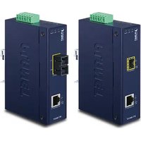
Thank you for purchasing PLANET Industrial EtherCAT Media Converter Kit. In the following sections, the term "Industrial EtherCAT Media Converter Kit" means the IECC-210T and IECC-210R.
Open the box of the Industrial EtherCAT Media Converter Kit and caref unpack it. The box should contain the following items:
IECC-210T and IECC-210R QR code

sheet x 1

Wall-mount Kit x 2 SFP dust cap x 2 Copper dust cap x 2



If any of these are missing or damaged, please contact your dealer immediately; if possible, retain the carton including the original packing material, and use them again to repack the product in case there is a need to return it to us for repair.
2. Product Features
● 1 x 100BASE-TX RJ45 bus interface
- 1 x 100BASE-FX SFP slot interface
● LED indicators for the input status
● 9 \~ 48V DC wide input voltage range
● Supports EtherCAT Distributed Clock (DC) mode
- EtherCAT conformance test tool verified
3. Product Specifications
| Model IECC-210T IECC-210R | |||
| Communication Interface | |||
| Copper | Port 1 x 100BASE-TX RJ45 | ||
| Distance between Stations | max. 100 m (100BASE-TX) | ||
| Data Transfer Medium | Ethernet/EtherCAT cable (min. cat5), shielded | ||
| Fiber | Port 1 x 100BASE-FX SFP slot | ||
| Distance between Stations | Depending on the ability of SFP module | ||
| Data Transfer Medium | Depending on the ability of SFP module | ||
| EtherCAT | |||
| Protocol EtherCAT | |||
| Power | |||
| Input Voltage Range 9~48V DC | |||
| Power Consumption 1.92W max. | |||
| Mechanical | |||
| Dimensions (W x D x H) 33 x 70 x 104mm | |||
| Installation DIN-rail mounting and wall mounting | |||
| Case Material IP30 metal | |||
| Environment | |||
| Operating Temperature -40~75°C | |||
| Storage Temperature -40~75°C | |||
| Relative Humidity | 5~95% (non-condensing) | ||
4. Hardware Introduction
4.1 Three-View Diagram
The three-view diagram of the Industrial EtherCAT Media Converter Kit consists of one 100BASE-TX RJ45 copper, one 100BASE-FX SFP slot, and one removable 4-pin power terminal block. The LED indicators are also located on the front panel.

Figure 1: IECC-210T/IECC-210R Three-View Diagram
Front View
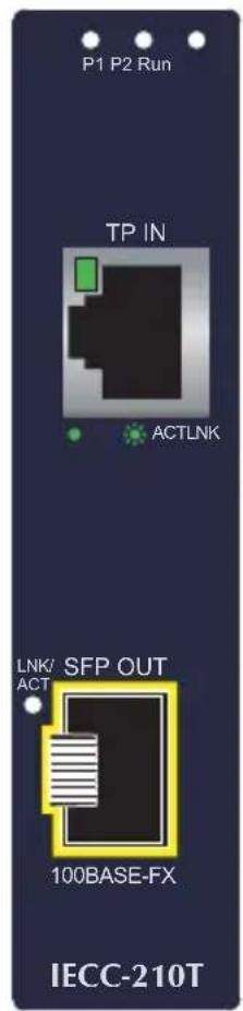

Figure 2: IECC-210T/IECC-210R Front View
LED Definition:
System
| LED Color Function | |||
| P1 Green Lights to indicate power 1 has power. | |||
| P2 Green Lights to indicate power 2 has power. | |||
| Run Green | Light The device is in the state of operation. | ||
| Single Flash | The device is in the state of operation without risk. | ||
| Blinking | The device is ready to be operated. | ||
| Off The device is in the initialization mode | |||
100BASE-TX RJ45 Port (Port Input/Port Output)
| LED Color Function | |||
| LNK/ACT | Green | Light Indicating that the port is linked up. | |
| Blinking | Indicating that the module is actively sending or receiving data over that port. | ||
| Off Indicating that the port is linked down. | |||
100BASE-FX SFP Port (Port Input/Port Output)
| LED Color Function | |||
| LNK/ACT | Green | Light Indicating that the port is linked up. | |
| Blinking | Indicating that the module is actively sending or receiving data over that port. | ||
| Off Indicating that the port is linked down. | |||
4.2 Wiring the Power Inputs
The 4-contact terminal block connector on the top panel of Industrial EtherCA Media Converter module is used for one DC power input. Please follow the steps below to insert the power wire.

When performing any of the procedures like inserting the wires or tightening the wire-clamp screws, make sure the power is OFF to prevent from getting an electric shock.
- Insert positive and negative DC power wires into contacts 1 and 2 for POWER.
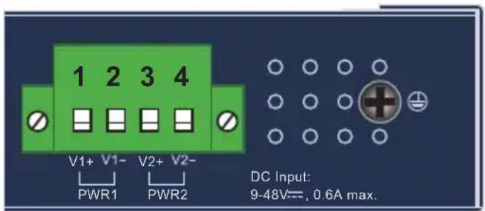
Figure 3: IECS-210T/IECC-210R Top View
- Tighten the wire-clamp screws for preventing the wires from loosening.

1 2 3 4 Power1 Power2 V1+ V1- V2+ V2-

Note
- The DC power input range is 9-48V DC.
- The device provides input voltage polarity protection.

Caution
PWR1 and PWR2 must provide exactly the same DV voltage power load balance while operating with dual power input.
4.3 Grounding the Device
Users MUST complete grounding wired with the device; otherwise, a sudden lightning could cause fatal damage to the device.


Note
EMD (Lightning) DAMAGE IS NOT COVERED UNDER WARRANTY.
5. Installation
This section describes the functionalities of the Industrial EtherCAT Media Converter module's components and guides you to installing it on the DIN rail and wall. Please read this chapter completely before continuing.

Note
This following pictures show the user how to install the device, and the device is not IECC-210-KIT.
5.1 DIN-rail Mounting Installation


5.2 Wall-mount Plate Mounting

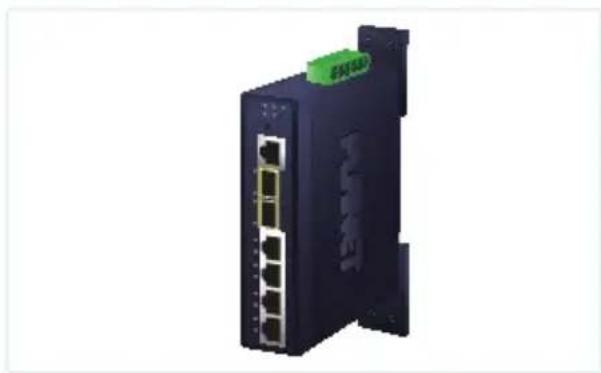
5.3 Side Wall-mount Plate Mounting


Caution
You must use the screws supplied with the wall-mounting brackets. Damage caused to the parts by using incorrect screw would invalidate your warranty.
6. Getting Started
This chapter provides a basic overview of how to configure and operate IECC-210 series.
6.1 Connecting the Power and the Host PC
Step 1: Connect both the TP IN port of the IECC-210T and RJ45 Ethernet port of Host PC.
Ensure that the network settings on the Host PC have been correctly configured and are functioning normally. Ensure that the Windows firewall and any anti-virus firewall is properly configured to allow incoming connections; if not, temporarily disable these functions.

Note
Attaching an ESC (EtherCAT Slave Controller) directly to an office network will result in network flooding, since the ESC will reflect any frame - especially broadcast frames - back into network (broadcast storm).
Step 2: Apply power to the IECS-210T
![graph LR A["PC"] -->|Connect the Host device to the IN Port on IECC-210T| B["USB Port"] B --> C["9-48V DC"] C --> D["9-pin connector with green pins"] D --> E["9-pin connector with red pin"] E --> F["9-pin connector with green pin"] F --> G["9-pin connector with red pin"] G --> H["9-pin connector wi…](/content/2026/05/900963/images/7cb715c643d500c1a6d93ec39345f2ae8a223ff21a319da63149a541d2c1644c.jpg)
Connect the V+ pin to positive terminal on a 9-48V DC power supply, and connect the V- pin to the negative terminal.
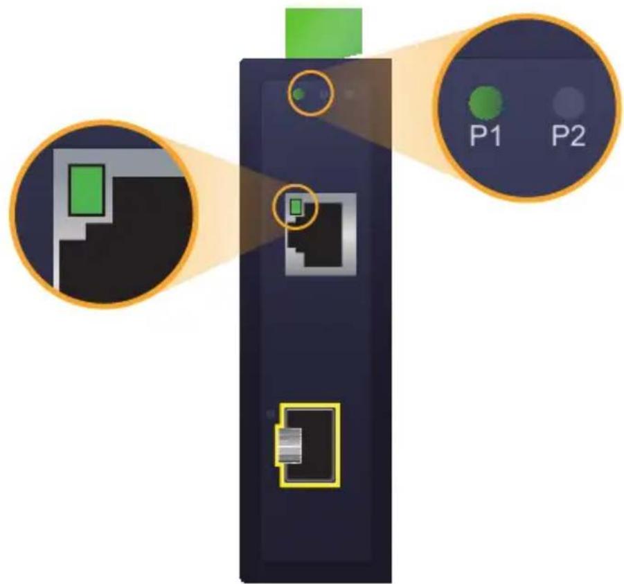
Step 3: Verify the "P1" LED indicator on the IECC-210T module is Green; "TP IN" LED indicator is Green.
6.2 Configuration and Operation
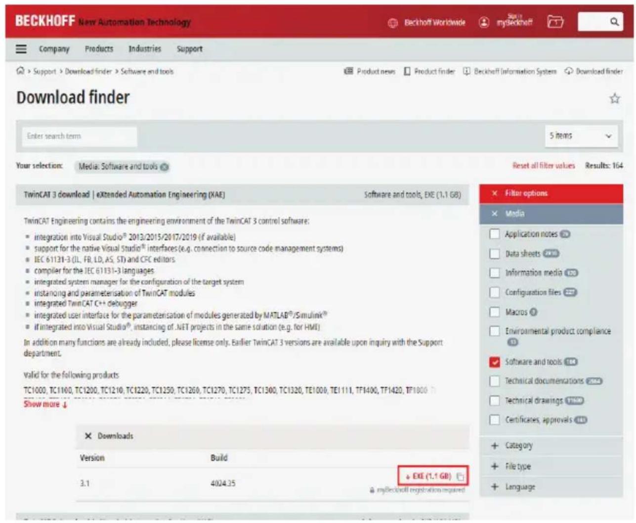
Beckhoff TwinCAT 3.x is the most commonly used EtherCAT Master software to operate the IECC-210T and IECC-210R.
Click on the link below to download Beckhoff TwinCAT 3.x:
https://www.beckhoff.com/en-en/support/download-finder/software-and-tools/
Inserting into the EtherCAT network

Note
Installation of the latest XML device description (ESI).
Make sure to use the latest installation description to install the latest XML device. This can be downloaded from PLANET website (https://www.planet.com.tw/en/support/downloads?method=keyword&keyword=IECC-210-KIT) and check the online FAQs for the installation of the XML device.
Step 1: Automatic Scanning
- The EtherCAT system must be in the safe, de-energized state before the IECC-210-KIT module is connected to EtherCAT network.
- Switch on the operating voltage, open the TwinCAT System Managed (Config mode), and scan the devices as shown in the print screen instruction below. Acknowledge all dialogs with "OK", so that the configuration is in the "FreeRun" mode.

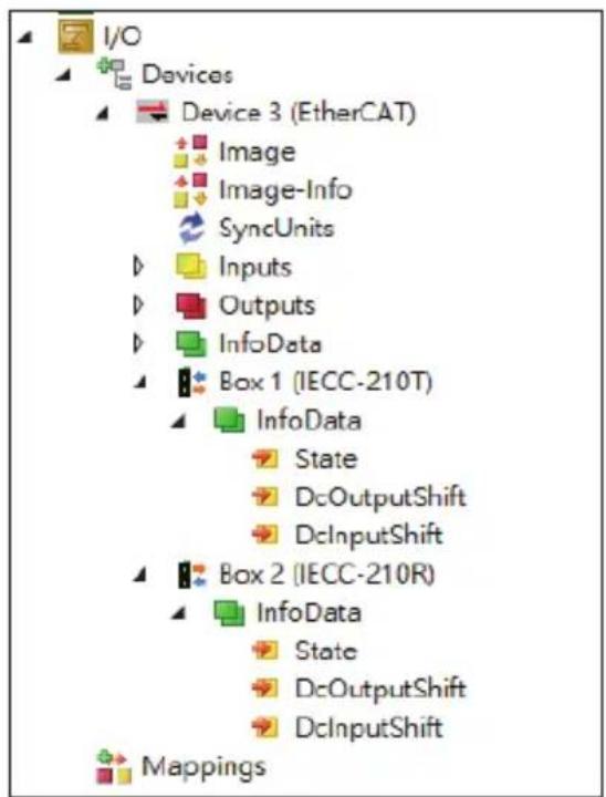
Step 2: Configuration via TwinCAT
In the left-hand window of the TwinCAT System Manager, click on the of the EtherCAT Box you wish to configure (IECC-210T and IECC-210R example). Click Box 1 or Box 2 to get and configure state.
Customer Support
Thank you for purchasing PLANET products. You can browse our online resource on PLANET web site first to check if it could solve your issue need more support information, please contact PLANET switch support team.
PLANET online FAQs:
http://www.planet.com.tw/en/support/faq.php
Support team mail address:

- INDUSTRIAL ETHERCAT MEDIA CONVERTER KIT
- TABLE OF CONTENTS
- PACKAGE CONTENTS
- PRODUCT FEATURES
- PRODUCT SPECIFICATIONS
- HARDWARE INTRODUCTION
- 4.1 THREE-VIEW DIAGRAM
- FRONT VIEW
- LED DEFINITION
- SYSTEM
- 100BASE-TX RJ45 PORT (PORT INPUT/PORT OUTPUT)
- 100BASE-FX SFP PORT (PORT INPUT/PORT OUTPUT)
- 4.2 WIRING THE POWER INPUTS
- 4.3 GROUNDING THE DEVICE
- INSTALLATION
- 5.1 DIN-RAIL MOUNTING INSTALLATION
- 5.2 WALL-MOUNT PLATE MOUNTING
- 5.3 SIDE WALL-MOUNT PLATE MOUNTING
- GETTING STARTED
- 6.1 CONNECTING THE POWER AND THE HOST PC
- 6.2 CONFIGURATION AND OPERATION
- INSERTING INTO THE ETHERCAT NETWORK
- STEP 1: AUTOMATIC SCANNING
- STEP 2: CONFIGURATION VIA TWINCAT
- CUSTOMER SUPPORT
Brand : Planet
Model : IECC-210-KIT
Category : Convertisseur réseau industriel