IFT-805AT - Media player Planet - Free user manual and instructions
Find the device manual for free IFT-805AT Planet in PDF.


| Product Type | 10/100BASE-TX to 100BASE-FX Industrial Media Converter |
| Model | IFT-805AT |
| Brand | Planet |
| Dimensions (W x D x H) | 135 mm x 85 mm x 32 mm |
| Weight | 430 g |
| Enclosure | IP30 slim-type metal case |
| Installation | DIN rail and wall-mount ear |
| Operating Temperature | -40°C to 75°C |
| Storage Temperature | -40°C to 85°C |
| Operating Humidity | 5% to 90% non-condensing |
| Storage Humidity | 5% to 90% non-condensing |
| Power Input | 12 to 48V DC, redundant with polarity reverse protection |
| Power Consumption | 3 watts / 10 BTU (maximum) |
| Protection | ESD (Ethernet): 6KV DC; Surge (Power): 6KV DC |
| Copper Port | 1 x 10/100BASE-TX RJ45, Auto-MDI/MDI-X |
| Fiber Port | 1 x 100BASE-FX SFP slot (distance depends on SFP module) |
| Standards Compliance | IEEE 802.3, IEEE 802.3u, IEEE 802.3x flow control |
| LED Indicators | Power 1, Power 2, Fault, Copper LNK/ACT, Copper 10/100, Fiber 100, Fiber LNK/ACT |
| Flow Control | Back pressure for half duplex, IEEE 802.3x pause frame for full duplex |
| Switching Architecture | Store-and-Forward with wire-speed filtering and forwarding |
| Max Frame Size | 1522 bytes |
| Emissions | FCC Class A, CE Class A |
| Stability Testing | IEC60068-2-32 (free fall), IEC60068-2-27 (shock), IEC60068-2-6 (vibration) |
Frequently Asked Questions - IFT-805AT Planet
User questions about IFT-805AT Planet
0 question about this device. Answer the ones you know or ask your own.
Ask a new question about this device
Download the instructions for your Media player in PDF format for free! Find your manual IFT-805AT - Planet and take your electronic device back in hand. On this page are published all the documents necessary for the use of your device. IFT-805AT by Planet.
USER MANUAL IFT-805AT Planet
10/100BASE-TX to 100BASE-FX
Industrial Media Converter
IFT-802T / IFT-802TS15 / IFT-805AT
User's Manual
Trademarks
Copyright © PLANET Technology Corp. 2015.
Contents are subject to revision without prior notice.
PLANET is a registered trademark of PLANET Technology Corp. All other trademarks belong to their respective owners.
Disclaimer
PLANET Technology does not warrant that the hardware will work properly in all environments and applications, and makes no warranty and representation, either implied or expressed, with respect to the quality, performance, merchantability, or fitness for a particular purpose.
PLANET has made every effort to ensure that this User's Manual is accurate; PLANET disclaims liability for any inaccuracies or omissions that may have occurred.
Information in this User's Manual is subject to change without notice and does not represent a commitment on the part of PLANET. PLANET assumes no responsibility for any inaccuracies that may be contained in this User's Manual. PLANET makes no commitment to update or keep current the information in this User's Manual, and reserves the right to make improvements to this User's Manual and/or to the products described in this User's Manual, at any time without notice.
If you find information in this manual that is incorrect, misleading, or incomplete, we would appreciate your comments and suggestions.
FCC Warning
This equipment has been tested and found to comply with the limits for a Class A digital device, pursuant to Part 15 of the FCC Rules. These limits are designed to provide
reasonable protection against harmful interference when the equipment is operated in a commercial environment. This equipment generates, uses, and can radiate radio frequency energy and, if not installed and used in accordance with the Instruction manual, may cause harmful interference to radio communications. Operation of this equipment in a residential area is likely to cause harmful interference in which case the user will be required to correct the interference at his own expense.
CE Mark Warning
This is a Class A product. In a domestic environment, this product may cause radio interference, in which case the user may be required to take adequate measures
WEEE Warning

To avoid the potential effects on the environment and human health as a result of the presence of hazardous substances in electrical and electronic equipment, end users of electrical and electronic equipment should understand the meaning of the crossed-out wheeled bin symbol. Do not dispose of WEEE as unsorted municipal waste and have to collect such WEEE separately.
Revision
PLANET 10/100BASE-TX to 100BASE-FX Industrial Media Converter User's Manual
For Models: IFT-802T, IFT-802TS15, IFT-805AT
Revision: 1.1 (June, 2015)
Part No: EM-IFT-80xT_v1.1 (2350-AH1140-001)
Table Of Contents
1. Introduction .... 5
1.1 Package Contents....5
1.2 How to Use This Manual....5
1.3 Product Features....6
1.4 Product Specifications....7
2. Installation 10
2.1 Product Description ...... 10
2.1.1 Media Converter Front Panel.... 12
2.1.2 LED Indicators.... 12
2.1.3 Media Converter Upper Panel.... 14
2.1.4 Wiring the Power Inputs.... 14
2.1.5 Wiring the Fault Alarm Contact 15
2.2 Mounting Installation....16
2.2.1 Installing DIN-Rail Mounting 17
2.2.2 Wall-mount Plate Mounting 19
3. Applications ...... 20
3.1 Installation Steps 20
4. Media Converter Operation 22
4.1 Learning.... 22
4.2 Forwarding & Filtering 22
4.3 Store-and-Forward 22
4.4 Auto-negotiation 23
5. Troubleshooting 24
Appendix A: Networking Connection 26
A.1 Media Converter's RJ45 Pin Assignments.... 26
A.2 RJ45 Cable Pin Assignments 26
A.3 Fiber Optical Cable Connection Parameter 27
1. Introduction
1.1 Package Contents
Check your package for the following parts:
• 10/100BASE-TX to 100BASE-FX Industrial Media Converter x 1
- User's Manual x 1
- DIN Rail Kit x 1
- Wall Mount Kit x 1
- Screws x 1 (set)
If any of these are missing or damaged, please contact your dealer immediately; if possible, retain the carton including the original packing material, and use them again to repack the product in case there is a need to return it to us for repair.
1.2 How to Use This Manual
This Industrial Media Converter User Manual is structured as follows:
Chapter 2 Installation
The chapter explains the feature, functionality and the physical installation of the Industrial Media Converter.
Chapter 3 Application
The chapter explains the Industrial Media Converter application.
Chapter 4 Media Converter operation
The chapter explains the Industrial Media Converter transmit operation.
Chapter 5 Troubleshooting
The chapter explains the troubleshooting of the Industrial Media Converter.
Appendix A
This chapter contains cable information of the Industrial Media Converter.
1.3 Product Features
Physical Port
IFT-802T
• 1-Port 10/100BASE-TX RJ45
- 1-Port 100BASE-FX interface for up to 2km (Multi-mode fiber 62.5/125μm / 50/125μm)
IFT-802TS15
• 1-Port 10/100BASE-TX RJ45
- 1-Port 100BASE-FX interface for up to 15km (Single mode fiber 9/125μm)
IFT-805AT
• 1-Port 10/100BASE-TX RJ45
- 1-Port 100BASE-FX SFP slot (Distance depends on SFP module)
Industrial Design
- Slim type IP30 metal case
- -40°C\~75°C operating temperature
• DIN rail and wall-mount design - 12 to 48V DC, redundant power with polarity reverse protect function and connective removable terminal block for master and slave power
• Supports EFT 6KV DC protection for power line
• Supports 6KV DC Ethernet ESD protection
Data Communication
- Complies with the IEEE 802.3, IEEE 802.3u Fast Ethernet standard
-
Auto-MDI/MDI-X detection and auto-negotiation with half-duplex / full-duplex modes for 10 /100BASE-TX RJ45 port
-
Store-and-Forward switching architecture
- Features Store-and-Forward mode with wire-speed filtering and forwarding rates
- Prevents packet loss with back pressure (half-duplex) and IEEE 802.3x pause frame flow control (full-duplex)
• Supports packet size of up to 1522bytes
• CSMA/CD protocol
• Automatic source address learning and aging
1.4 Product Specifications
| Product IFT-802T IFT-802TS15 IFT-805AT | |||
| Hardware Specifications | |||
| 10/100BASE-TX Port | 1 RJ45 Auto-MDI/MDI-X port | ||
| 100BASE-FX Port | 1 SC Interface 1 SFP Slot | ||
| Fiber Port Type SC / Multi-mode SC | / Single mode | Vary on module | |
| Cable Distance 2km 15km | |||
| Optical Frequency | 1310nm 1310nm | ||
| Launch Power (dBm) | Max: -14Min: -20 | Max: 0Min: -20 | |
| Receive Sensitivity (dBm) | -32 -32 | ||
| Maximum Input Power (dBm) | -14 0 | ||
| Dimensions (W x D x H) | 135mm x 85mm x 32mm | ||
| Weight 430g | |||
| Installation DIN rail kit and wall-mount ear | |||
| Maximum Frame Size | Packet size of 1522bytes | ||
| Flow Control | Back pressure for half duplex, IEEE 802.3x pause frame for full duplex | ||
| Enclosure IP-30 slim-type metal case | |||
| LED Indicator | System:Power 1 (green)Power 2 (green)Fault (green)1 x copper port:10/100 (green)LNK/ACT(green)1 x 100FX port:100 (green)LNK/ACT (green) | ||
| Power Input | 12 to 48V DC redundant power with polarity reverse protection function | ||
| Power Consumption | 3 watts / 10BTU (maximum) | ||
| Protection | ESD (Ethernet): 6KV DCSurge (Power): 6KV DC | ||
| Operating Temperature | -40~75 degrees C | ||
| Operating Humidity | 5~90% non-condensing | ||
| Storage Temperature | -40~85 degrees C | ||
| Storage Humidity | 5~90% non-condensing | ||
| Speed | Twisted-pair:10/20Mbps for half / full-duplex100/200Mbps for half / full duplexFiber-optic:200Mbps for full-duplex | ||
| Network Cables | 10/100BASE-TX:2-pair UTP Cat. 3, 4, 5 (100 meters, max.)EIA/TIA-568 100-ohm STP (100 meters, max.)100BASE-FX:IFT-802T: Multi-mode optic fiber 62.5/125μm / 50/125μm (2km)IFT-802TS15: Single mode optic fiber 9/125μm (15km)IFT-805AT: SFP Slot (depending on SFP module) | ||
| Standards Conformance | |||
| Emissions FCC Class A, CE Class A | |||
| Standards Compliance | IEEE 802.3 10BASE-TIEEE 802.3u 100BASE-TX / 100BASE-FXIEEE 802.3x flow control and back pressure | ||
| Stability Testing | IEC60068-2-32 (free fall)IEC60068-2-27 (shock)IEC60068-2-6 (vibration) | ||
2. Installation
This section describes the functionalities of the Industrial Media Converter's components and guides you how to install it on the desktop. Basic knowledge of networking is assumed. Please read this chapter completely before continuing.
In the following section, the term “Industrial Media Converter” means the IFT-802T / 802TS15 / 805AT.
2.1 Product Description
The IFT-80xT is an industrially-hardened media converter specially designed to operate under the environment temperature range of -40 to 75°C. The IFT-80xT is highly reliable and stable when operating in the harsh environment. The IFT-80xT provides high level of immunity to electromagnetic interference and heavy electrical surges typical of environments found on plant floors or in curb side traffic control cabinets.
The IFT-80xT is packaged in a compact, IP30 standard metal that allows either DIN or panel mounting for efficient use of cabinet space. The media converter provides an integrated power supply with a wide range of voltages (12 to 48V DC) for worldwide operability or dual-redundancy, reversible polarity, and 24V DC and 48V DC power supply inputs for high availability applications requiring dual or backup power inputs.
The IFT-80xT provides one 10/100BASE-TX optic-fiber SC/SFP interface and one 100BASE-FX optic-fiber SC/SFP interface. It provides multi-mode or single-mode 100BASE-FX SC interface and 100BASE-FX SFP slot. The fiber transmit distance of the IFT-802T can be 2km while that of the IFT-802TS15 is 15km and that of the IFT-805AT varies depending on SFP module.
With Fast Ethernet SFP interface, the IFT-805AT is highly
reliable and flexible to extend the distance from 2km to 60km, depending on the MFB family Fast Ethernet SFP modules.
MFB family Fast Ethernet SFP module comes with one of the following models. The following list the available modules for the IFT-805AT
| Fast Ethernet SFP Module List | ||
| Model Interface Fiber Connector and Distance | ||
| MFB-FX | SFP-Port100BASE-FX Module | LC, Multi-Mode (1310nm)-2km (-0~50°C) |
| MFB-F20 | SFP-Port100BASE-FX Module | LC, Single Mode (1310nm) -20km (-0~50°C) |
| MFB-F40 | SFP-Port100BASE-FX Module | LC, Single Mode (1310nm) -40km (-0~50°C) |
| MFB-F60 | SFP-Port100BASE-FX Module | LC, Single Mode (1310nm) -60km (-0~50°C) |
| MFB-FA20 | SFP-Port100BASE-BX Module | LC WDM, Single Mode(TX:1310nm, RX:1550nm) -20km (-0~50°C) |
| MFB-FB20 | SFP-Port100BASE-BX Module | LC WDM, Single Mode(TX:1550nm, RX:1310nm) -20km (-0~50°C) |
| MFB-TFX | SFP-Port100BASE-FX Module | LC, Multi-Mode (1310nm)-2km (-40~75°C) |
| MFB-TF20 | SFP-Port100BASE-FX Module | LC, Single Mode (1310nm) -20km (-40~75°C) |
* Models with the last two numbers indicate the maximum distance in km.
2.1.1 Media Converter Front Panel
Figure 2-1 & 2-2 & 2-3 show a front panel of Industrial Media Converter.
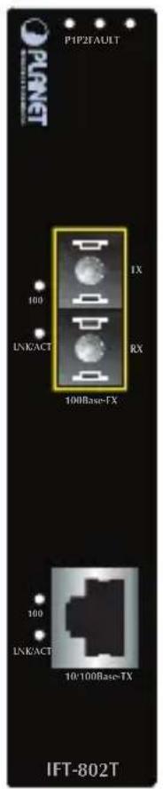
Figure 2-1 IFT-802T Front Panel
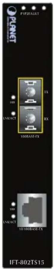
Figure 2-2 IFT-802TS15 Front Panel
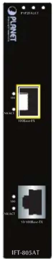
Figure 2-3 IFT-805AT Front Panel
2.1.2 LED Indicators
System
| LED Color Function | |
| P1 Green Lit: Indicates power 1 has power. | |
| P2 Green Lit: Indicates power 2 has power. | |
| FAULT Green | Lit: Indicates either power 1 or power 2 has no power. |
10/100BASE-TX RJ45 Port
| LED Color Function | ||
| 10/100 Green | Lit: Indicates TP port is successfully connecting to the network at 100Mbps. | |
| Off: Indicates TP port is successfully connecting to the network at 10Mbps. | ||
| LNK/ACT Green | Lit: Indicates the link through that port is successfully established. | |
| Blinking: Indicates TP port is actively sending or receiving data over that port. | ||
➢ 100BASE-FX SC / SFP Fiber Interface
| LED Color Function | ||
| 100 Green | Lit: Indicates fiber port is successfully connecting to the network at 100Mbps. | |
| LNK/ACT | Green | Lit: Indicates the link through that port is successfully established. |
| Blinking: Indicates fiber port is actively sending or receiving data over that port. | ||
2.1.3 Media Converter Upper Panel
The upper panel of the Industrial Media Converter consists one terminal block connector within two DC power inputs. Figure 2-4 shows the upper panel of the Industrial Media Converter.
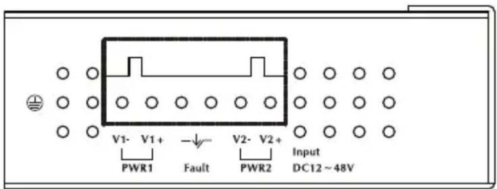
Figure 2-4 Industrial Media Converter Upper Panel.
2.1.4 Wiring the Power Inputs
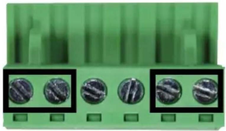
The 6-contact terminal block connector on the top panel of Industrial Media Converter is used for two DC redundant inputs. Please follow the steps below to insert the power wire.
- Insert positive / negative DC power wires into Contacts 1 and 2 for Power 1 or 5 and 6 for Power 2.
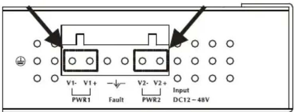
V1- V1 + V2 - V2 +
- Tighten the wire-clamp screws for preventing the wires from loosening
natural_image
Close-up of a green plastic connector with five circular screw holes, shown in two black zoomed-in insets (no text or symbols visible)123456
Power 1 Fault Power 2
- + - +

Note
The wire gauge for the terminal block should be in the range of 12 to 24 AWG.
2.1.5 Wiring the Fault Alarm Contact
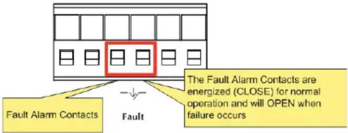
The fault alarm contacts are in the middle of the terminal block connector as the picture shows below. After inserting the wires, the Industrial Media Converter will detect the fault status of the power failure, or port link failure (available for managed model) and then form an open circuit. The following illustration shows an application example for wiring the fault alarm contacts.
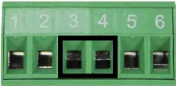
Insert the wires into the fault alarm contacts.

Note
- The wire gauge for the terminal block should be in the range of 12 to 24 AWG.
- Alarm relay circuit accepts up to 30V, max. 3A currents.
2.2 Mounting Installation
This section describes how to install the Industrial Media Converter and make connections to it. Please read the following steps to perform the procedures in the order being presented.

Note
In the installation steps below, this Manual uses the IGS-801 (PLANET 8-port Industrial Gigabit Switch) as an example. However, the steps for PLANET Industrial Media Converter are similar.
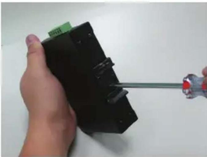
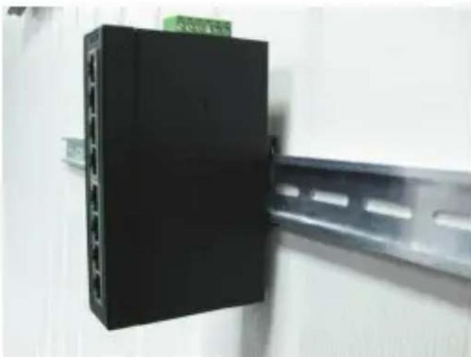
2.2.1 Installing DIN-Rail Mounting
Follow the steps below for the DIN-rail mounting of the Industrial Media Converter:
natural_image
Hand holding a black electronic device with a screwdriver inserted, no visible text or symbolsStep 1: Screw the DIN-rail on the Industrial Media Converter.
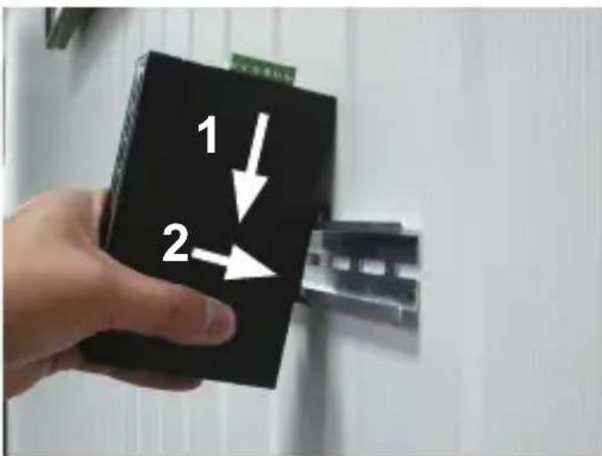
Step 2: Lightly slide the DIN-rail into the track.
natural_image
Black electronic device with multiple ports mounted on a metal frame (no visible text or symbols)Step 3: Make sure the DIN-rail is tightly on the track.
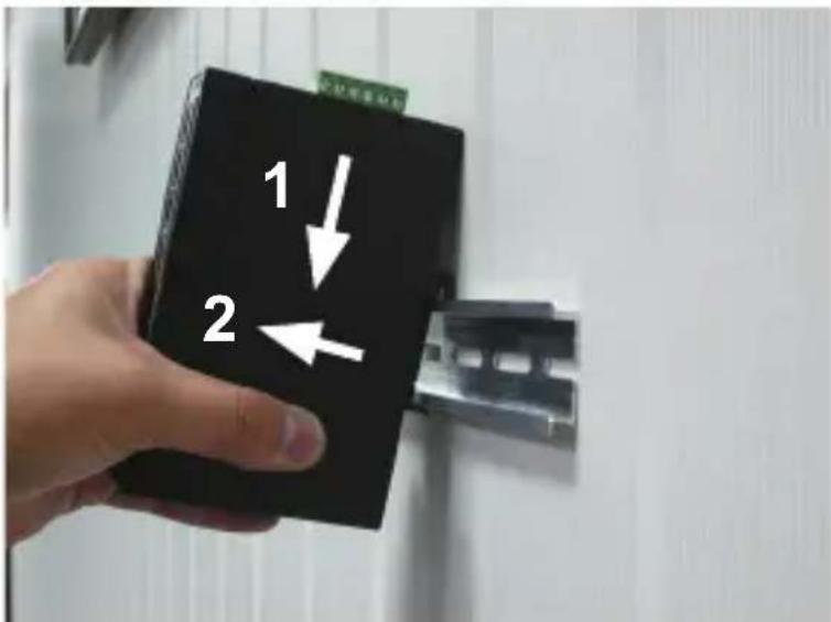
Step 4: To remove Industrial Media Converter from the track, lightly lift it up.
2.2.2 Wall-mount Plate Mounting
To install the Industrial Media Converter on the wall, please follow the instructions described below:
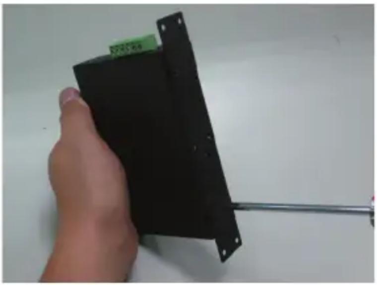
Step 1: Remove the DIN-rail from the Industrial Media Converter; loosen the screws to remove the DIN-rail.
Step 2: Place the wall-mount plate on the rear panel of the Industrial Media Converter.
natural_image
Hand holding a black electronic device with a metal rod extending from it (no visible text or symbols)Step 3: Use the screws to screw the wall-mount plate on the Industrial Media Converter.
Step 4: Use the hook holes at the corners of the wall-mount plate to hang the Industrial Media Converter on the wall.
Step 5: To remove the wall-mount plate, reverse the steps above.
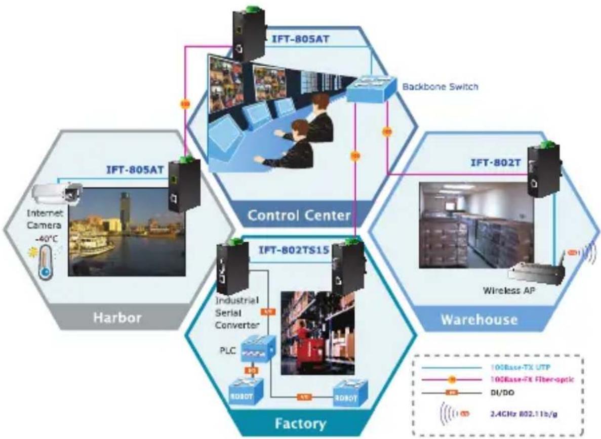
3. Applications
In this section, how to install Industrial Media Converter and its installation points are described below:
flowchart
graph TD
    subgraph Control Center
        A["Control Center"]
        B["Control Center"]
        C["Control Center"]
        D["Control Center"]
        E["Control Center"]
        F["Control Center"]
        G["Control Center"]
        H["Control Center"]
        I["Control Center"]
        J["Control Center"]
        K["Control Center"]
    end

    subgraph Warehouse
        L["Warehouse"]
        M["Warehouse"]
        N["Warehouse"]
        O["Warehouse"]
        P["Warehouse"]
    end

    subgraph Factory
        Q["Factory"]
        R["Factory"]
        S["Factory"]
        T["Factory"]
    end

    I -->|IFT-802TS15| U["Industrial Serial Converter PLC"]
    I -->|IFT-802T| V["Wireless AP"]
    I --> W["IFT-805AT"]
    I --> X["IFT-805AT"]
    I --> Y["Backbone Switch"]
    I --> Z["Internet Camera -40°C"]
    I --> AA["10GBase-TX UTP"]
    I --> AB["10GBase-FX Fiber-optic"]
    I --> AC["DI/DO"]
    I --> AD["2.4GHz 802.11b/g"]
3.1 Installation Steps
Step 1: Unpack the Industrial Media Converter.
Step 2: Screw DIN-rail on the Industrial Media Converter. Please refer to the DIN-rail Mounting section for DIN-rail installation if the DIN-rail is not screwed on the Industrial Media Converter. If you want to wall-mount the Industrial Media Converter, please refer to the Wall-mount Plate Mounting section for wall-mount plate installation.
Step 3: To hang the Industrial Media Converter on the DIN-rail track or wall, please refer to the Mounting Installation section.
Step 4: Power on the Industrial Media Converter. Please refer to the Wiring the Power Inputs section for power input. The power LED on the Industrial Media Converter will light up. Please refer to the LED Indicators section for the meaning of LED lights.
Step 5: Prepare the twisted-pair, straight-through Category 5 cable for Ethernet connection.
Step 6: Insert one side of Cat.5 cables into the Industrial Media Converter Ethernet port (RJ45 port) and the other side into the Ethernet port (RJ45 port) of a network devices, for example, switch, PC or server. The UTP port (RJ45) LED on the Industrial Media Converter will light up when the cable is connected with the network device. Please refer to the LED Indicators section for the definitions of LEDs.

Note
Be sure the connected network devices support MDI/MDI-X. If it does not support them, use the crossover category 5 cable.
Step 7: Insert the fiber cable from the IFT-802T / 802TS15 / 805AT to the fiber network. TX and RX must be paired at both ends. The optical port LED on the Industrial Media Converter will light up when the cable is connected with the network device. Please refer to the LED Indicators section for the definitions of LEDs
Step 8: When all the connections are all set and LED lights all show normal, the installation is completed.
4. Media Converter Operation
4.1 Learning
When one packet comes in from any port, the Industrial Media Converter will record the source address, port number and the other related information in the address table. This information will be used to decide whether forwarding or filtering is for future packets.
4.2 Forwarding & Filtering
When one packet comes from a port of the Industrial Media Converter, it will also check the destination address besides the source address learning. The Industrial Media Converter will look up the address table for the destination address. If not found, this packet will be forwarded to all the other ports except the port which this packet comes in. And these ports will transmit this packet to the network it connected. If found, and the destination address is located at a different port from this packet comes in, the Industrial Media Converter will forward this packet to the port where this destination address is located according to the information from address table. But, if the destination address is located at the same port with this packet comes in, then this packet will be filtered, thereby increasing the network throughput and availability
4.3 Store-and-Forward
Store-and-Forward is one type of packet-forwarding techniques. A Store-and-Forward Industrial Media Converter stores the incoming frame in an internal buffer and does the complete error checking before transmission. Therefore, no error packets occur. it is the best choice when a network needs efficiency and stability.
The Industrial Media Converter scans the destination address from the packet-header, searches the routing table provided for the incoming port and forwards the packet, only if required. The fast forwarding makes the media converter attractive for connecting servers directly to the network, thereby increasing throughput and availability. However, the media converter is the most commonly used to segment the existing hubs, which nearly always improve the overall performance.
Owing to the learning function of the Industrial Media Converter, the source address and corresponding port number of each incoming and outgoing packet are stored in a routing table. This information is subsequently used to filter packets whose destination address is on the same segment as the source address. It confines network traffic to its respective domain, reducing the overall load on the network.
The Industrial Media Converter performs "Store-and-Forward"; therefore, no error packets occur. More reliably, it reduces the re-transmission rate. No packet loss will occur
4.4 Auto-negotiation
The STP ports on the Industrial Media Converter have a built-in "auto-negotiation". This technology automatically sets the best possible bandwidth when a connection is established with another network device (usually at Power On or Reset). This is done by detecting the modes and speeds within seconds right after both devices are connected. Both 10BASE-T and 100BASE-TX devices can connect with the port in either half- or full-duplex mode.
5. Troubleshooting
This chapter contains information to help you solve issues. If the Industrial Media Converter is not functioning properly, make sure the Industrial Media Converter was set up according to instructions in this manual.
The per port LED is not lit
Solution:
Check the cable connection of the Industrial Media Converter.
Performance is bad
Solution:
Check the speed duplex mode of the partner device. The Industrial Media Converter runs in the auto-negotiation mode and if the partner is set to half duplex, then the performance will be poor.
Per port LED is lit, but the traffic is irregular
Solution:
Check that the attached device is not set to dedicate full duplex. Some devices use a physical or software switch to change duplex modes. Auto-negotiation may not recognize this type of full-duplex setting.
Why the Industrial Media Converter doesn't connect to the network
Solution:
Check per port LED on the Industrial Media Converter. Try another port on the Industrial Media Converter Make sure the cable is installed properly. And make sure the cable is the right type to turn off the power. After a while, turn on the power again.
Why the Industrial Media Converter doesn't connect to the network
Solution:
Check per port LED on the Industrial Media Converter. Try another port on the Industrial Media Converter Make sure the cable is installed properly. And make sure the cable is the right type to turn off the power. After a while, turn on the power again.
When I connect IFT-80xT to device with 100BASE-FX interface, the 100BASE-FX fiber connection fails
Solution:
-
Please check the fiber connection between the two devices is correct.
-
Please check the 100BASE-FX interface from other devices run in the same full duplex mode
Appendix A: Networking Connection A.1 Media Converter's RJ45 Pin Assignments
10/100Mbps, 10/100BASE-TX
| RJ45 Connector Pin Assignment | ||
| Contact | MDI Media Dependent Interface | MDI-X Media Dependent Interface-Cross |
| 1 Tx + (transmit) Rx + (receive) | ||
| 2 Tx - (transmit) Rx - (receive) | ||
| 3 Rx + (receive) Tx + (transmit) | ||
| 4, 5 Not used | ||
| 6 Rx - (receive) Tx - (transmit) | ||
| 7, 8 Not used | ||
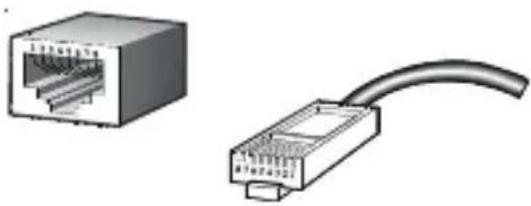
A.2 RJ45 Cable Pin Assignments
natural_image
Two types of Ethernet connectors shown: a separate internal port and a straight cable (no text or symbols)The standard RJ45 receptacle/connector
There are 8 wires on a standard UTP/STP cable and each wire is color-coded. The following shows the pin allocation and color of straight-through cable and crossover cable connection:
Figure A-1: Straight-through and Crossover Cables
Please make sure your connected cables are with the same pin assignment and color as the above diagram before deploying the cables into your network
A.3 Fiber Optical Cable Connection Parameter
The wiring details are as shown below:
■ Fiber Optic Patch Cables:
| Standard Fiber Type Cable Specification | |
| 100BASE-FX(1300nm) | Multi-mode 50/125μm or 62.5/125μm |
| 100BASE-FX(1310nm) | Multi-mode 50/125μm or 62.5/125μm |
| Single mode 9/125μm | |
EC Declaration of Conformity
For the following equipment:
*Type of Product: 10/100BASE-TX to 100BASE-FX Industrial Media Converter with Wide Operating Temperature
*Model Number: IFT-802T / IFT-802TS15 / IFT-805AT
* Produced by:
Manufacturer's Name : Planet Technology Corp.
Manufacturer's Address: 11F, No 96, Min Chuan Road,
Hsin Tien, Taipei, Taiwan, R.O.C.
is herewith confirmed to comply with the requirements set out in the Council Directive on the Approximation of the Laws of the Member States relating to Electromagnetic Compatibility Directive on (2004/108/EC).
For the evaluation regarding the EMC, the following standards were applied:
EN55022 (CLASS A: 2006)
EN 61000-3-2 (2006)
EN 61000-3-3 (1995 / A1: 2001 / A2: 2005)
EN55024 (1998 / A1: 2001 / A2: 2003)
IEC 61000-4-2 (2001)
IEC 61000-4-3 (2008)
IEC 61000-4-4 (2004)
IEC 61000-4-5 (2005)
IEC 61000-4-6 (2008)
IEC 61000-4-8 (2001)
IEC 61000-4-11 (2004)
Responsible for marking this declaration if the:
Manufacturer ☐ Authorized representative established within the EU
Authorized representative established within the EU (if applicable):
Company Name: Planet Technology Corp.
Company Address: 11F, No.96, Min Chuan Road, Hsin Tien, Taipei, Taiwan, R.O.C
Person responsible for making this declaration
Name, Surname Kent Kang
Position / Title : Product Manager
Taiwan
Place
26 ^th July, 2010
Date

Legal Signature
- 10/100BASE-TX to 100BASE-FX
- Industrial Media Converter
- Trademarks
- Disclaimer
- FCC Warning
- CE Mark Warning
- WEEE Warning
- Revision
- Table Of Contents
- Introduction .... 5
- Installation 10
- Applications ...... 20
- Media Converter Operation 22
- Troubleshooting 24
- Appendix A: Networking Connection 26
- Introduction
- Package Contents
- How to Use This Manual
- Chapter 2 Installation
- Chapter 3 Application
- Chapter 4 Media Converter operation
- Chapter 5 Troubleshooting
- Appendix A
- Product Features
- Physical Port
- IFT-802T
- IFT-802TS15
- IFT-805AT
- Industrial Design
- Data Communication
- Installation
- Product Description
- Media Converter Front Panel
- LED Indicators
- System
- Media Converter Upper Panel
- Wiring the Power Inputs
- Wiring the Fault Alarm Contact
- Mounting Installation
- Installing DIN-Rail Mounting
- Wall-mount Plate Mounting
- Applications
- Installation Steps
- Media Converter Operation
- Learning
- Forwarding & Filtering
- Store-and-Forward
- Auto-negotiation
- Troubleshooting
- The per port LED is not lit
- Solution:
- Performance is bad
- Per port LED is lit, but the traffic is irregular
- Why the Industrial Media Converter doesn't connect to the network
- When I connect IFT-80xT to device with 100BASE-FX interface, the 100BASE-FX fiber connection fails
- Appendix A: Networking Connection A.1 Media Converter's RJ45 Pin Assignments
- A.2 RJ45 Cable Pin Assignments
- A.3 Fiber Optical Cable Connection Parameter
- EC Declaration of Conformity
Brand : Planet
Model : IFT-805AT
Category : Media player