
M9950 - Inverter MITSUBISHI - Free user manual and instructions
Find the device manual for free M9950 MITSUBISHI in PDF.


| Product Type | Power Inverter |
| Brand | Mitsubishi |
| Model | M9950 |
| Input Voltage (DC) | 12V / 24V (auto-sensing) |
| Output Voltage (AC) | 120V / 230V selectable |
| Continuous Power Output | 1000W |
| Peak Power Output | 2000W (for up to 5 seconds) |
| Output Waveform | Pure Sine Wave |
| Efficiency | >90% at full load |
| Dimensions (L x W x H) | 290 x 180 x 85 mm |
| Weight | 1.8 kg |
| Cooling | Temperature-controlled fan |
| Protections | Overload, short circuit, over temperature, low battery alarm, reverse polarity |
| Display | LED indicators (Power, Fault, Overload) |
| USB Output | 1x USB-A (5V/2.1A) |
| Remote Control Support | Yes (optional remote, sold separately) |
| Warranty | 2 years limited |
| Maintenance | Keep vents clean; wipe with dry cloth; check cable connections monthly |
| Safety Certifications | CE, RoHS, UL listed |
| Spare Parts Availability | Replacement fans and fuses available from authorized dealers |
| Repairability | Modular design; user-replaceable fuses; professional service for internal repairs |
| General Information | Designed for residential and commercial use; suitable for sensitive electronics |
Frequently Asked Questions - M9950 MITSUBISHI
User questions about M9950 MITSUBISHI
0 question about this device. Answer the ones you know or ask your own.
Ask a new question about this device
Download the instructions for your Inverter in PDF format for free! Find your manual M9950 - MITSUBISHI and take your electronic device back in hand. On this page are published all the documents necessary for the use of your device. M9950 by MITSUBISHI.
USER MANUAL M9950 MITSUBISHI
UNINTERRUPTIBLE POWER SUPPLY SYSTEM
MODEL
M9950 SERIES
OWNERS / TECHNICAL MANUAL
60\~600kVA
(Inclusive Parallel Operation System Application)
TABLE OF CONTENTS
LIST OF TABLES ...... ii
LIST OF FIGURES .... iii
HOW TO USE THIS MANUAL iv
1.0 INTRODUCTION 1-1
1.1 SAFETY PRECAUTIONS 1-2
1.2 GENERAL 1-5
1.3 DEFINITIONS 1-6
1.4 OPERATION OVERVIEW 1-7
1.5 SYSTEM SINGLE LINE DIAGRAM 1-17
1.6 SPECIFICATIONS 1-19
2.0 OPERATION CONTROLS AND INDICATORS 2-1
2.1 LED DISPLAY 2-2
2.2 EPO BUTTON 2-2
2.3 LIQUID CRYSTAL DISPLAY 2-3
2.4 EXTERNAL SIGNAL TERMINAL BLOCK 2-10
3.0 INSTALLATION AND OPERATION 3-1
3.1 TRANSPORTATION AND INSTALLATION 3-1
3.2 INSTALLATION PROCEDURE 3-1
3.3 PROCEDURE FOR CABLE CONNECTIONS 3-2
3.4 RECOMMENDED CABLE SIZES 3-5
3.5 OPERATING PROCEDURES 3-15
4.0 RESPONSE TO UPS FAILURE 4-1
5.0 PARTS REPLACEMENT 5-1
6.0 FAULT CODES 6-1
7.0 DAILY INSPECTION 7-1
LIST OF TABLES
TABLE 1.1 UPS Installation Environment.... 1-3
TABLE 1.2 Rating of Bypass Input Circuit Breaker 1-4
TABLE 1.3 System Diagram 1-17
TABLE 1.4 Power Specifications 1-19
TABLE 1.5 UPS Module Information.... 1-19
TABLE 1.6 Detail of Specifications 1-20
TABLE 1.7 Rating of Contactors, Breaker and Fuses 1-21
TABLE 3.1 How to Transport and Install the System 3-1
TABLE 3.2 List of UPS Weights.... 3-1
TABLE 3.3 Recommended Cable Sizes (AC Input) 3-5
TABLE 3.4 Recommended Cable Sizes (AC Output, Bypass Input) ...... 3-5
TABLE 3.5 Recommended Cable Sizes (DC Connection) 3-5
TABLE 6.1 Fault Code 6-2
TABLE 7.1 How to perform daily inspection 7-1
LIST OF FIGURES
FIGURE 1.1 Single Line Diagram-Normal Operation 1-7
FIGURE 1.2 Single Line Diagram-Bypass Operation 1-8
FIGURE 1.3 Single Line Diagram-Battery Operation.... 1-9
FIGURE 1.4-a UPS Parts Location (500,600 kVA) 1-11
FIGURE 1.4-b UPS Parts Location (300,400 kVA) 1-12
FIGURE 1.4-c UPS Parts Location (200 kVA) 1-13
FIGURE 1.5 Display PCB DPAU-81 1-14
FIGURE 1.6 External I/F PCB IOAU-09 1-14
FIGURE 1.7 Parallel I/F PCB IFAU-09 1-14
FIGURE 1.8 MAIN PCB UPHR-K* 1-15
FIGURE 2.1 Operation/Display Panel 2-1
FIGURE 2.2-a Main screen (EN).... 2-3
FIGURE 2.2-b Main screen (CN).... 2-3
FIGURE 2.3-a Startup/Shutdown guidance(EN).... 2-4
FIGURE 2.3-b Startup/Shutdown guidance(CN).... 2-4
FIGURE 2.3-c Startup guidance(EN) 2-4
FIGURE 2.3-d Startup guidance(CN) 2-4
FIGURE 2.3-e Shutdown guidance(EN).... 2-4
FIGURE 2.3-f Shutdown guidance(CN).... 2-4
FIGURE 2.4-a Input values (EN) 2-5
FIGURE 2.4-b Input values (CN).... 2-5
FIGURE 2.4-c Output values(EN) 2-5
FIGURE 2.4-d Output values(CN) 2-5
FIGURE 2.4-e Values in Battery operation (EN).... 2-5
FIGURE 2.4-f Values in Battery operation (CN).... 2-5
FIGURE 2.5-a Remote/Local operation select (EN).... 2-6
FIGURE 2.5-b Remote/Local operation select (CN) 2-6
FIGURE 2.5-c Date & Time adjustment (EN).... 2-6
FIGURE 2.5-d Date & Time adjustment (CN).... 2-6
FIGURE 2.6-a Log menu(EN).... 2-7
FIGURE 2.6-b Log menu(CN) 2-7
FIGURE 2.6-c Event log(EN).... 2-7
FIGURE 2.6-d Event log(CN) 2-7
FIGURE 2.6-e Battery log(EN) 2-7
FIGURE 2.6-f Battery log(CN) 2-7
FIGURE 2.7-a Main Screen (EN)(Battery Operation) 2-8
FIGURE 2.7-b Main Screen (CN)(Battery Operation) 2-8
FIGURE 2.7-c Measurement screen (EN)(Battery Operation).... 2-8
FIGURE 2.7-d Measurement screen (CN)(Battery Operation) 2-8
FIGURE 2.8-a Main Screen (Fault Indication)(EN) 2-9
FIGURE 2.8-b Main Screen (Fault Indication)(CN) 2-9
FIGURE 2.9-a Message Screen (EN) 2-9
FIGURE 2.9-b Message Screen (CN) 2-9
FIGURE 2.10-a External Signal Terminal Block (TN2) 2-10
FIGURE 2.10-b External Signal Terminal Block (TN1) 2-11
FIGURE 2.11 Control Wiring for External Contacts 2-12
FIGURE 2.12 Remote "Start" Contact Connections 2-13
FIGURE 3.1 UPS Terminal Designation 3-6
FIGURE 3.2-a Diagram of input/output bus bars and terminal blocks (500,600kVA) .... 3-7
FIGURE 3.2-b Diagram of input/output bus bars and terminal blocks (300,400kVA) .... 3-8
FIGURE 3.2-c Diagram of input/output bus bars and terminal blocks (200kVA) ...... 3-9
FIGURE 3.3 Diagram of Power wire & Control wire Inter-connect between UPS and Battery .... 3-10
FIGURE 3.4 Diagram of Power wire Connect (Parallel Connection).... 3-11
FIGURE 3.5-a Diagram of Power and Control wire Connect (2 units Connection) ...... 3-12
FIGURE 3.5-b Diagram of Power and Control wire Connect (3 or 4 units Connection).. 3-13
FIGURE 3.5-c Diagram of Power and Control wire Connect (5 to 8 units Connection) .. 3-14
FIGURE 3.6 Circuit protectors location 3-15
FIGURE 3.7 Circuit configuration of single module system.... 3-16
FIGURE 3.8 Circuit configuration of Individual Bypass Parallel Redundancy System. 3-29
FIGURE 3.9 Dynamic Regenerative Load with UPS System 3-40
HOW TO USE THIS MANUAL
This manual is designed for ease of use, giving the user easy and quick reference to information.
This manual uses notice icons to draw attention to the user important information regarding the safe operation and installation of the UPS. The notice icons used in this manual are explained below, and should be taken into account and adhered to whenever they appear in the text of this manual.

Warning: A warning symbol shows potentially hazardous situation or condition which could result in personal injury or death, if not avoided.

Caution: A caution symbol shows potentially hazardous situation or condition which could result in personal injury or equipment damage, if not avoided.

Note: A Note symbol shows the information the user or the service personnel should observe during the UPS operation or service work.

Prohibit: A prohibit symbol shows the act the user or the service personnel should NEVER perform during the UPS installation, operation or service work.
Safety Recommendations: If any problems are encountered while following this manual, TMEIC field service group assistance and correspondence is recommended.
1.0 INTRODUCTION
The MITSUBISHI Uninterruptible Power Supply System (UPS) is designed to provide many years of reliable protection from power failure, brown-outs, line noise, and voltage transients. To ensure optimum performance of the equipment, follow the manufacturer's instructions. This manual contains descriptions required to operate the UPS. Please read this manual carefully and retain it for future reference.

IMPORTANT SAFETY INSTRUCTIONS SAVE THESE INSTRUCTIONS
This manual contains important instructions for the M9950 SERIES Uninterruptible Power Supply Systems that should be followed during installation and maintenance of the UPS and batteries.

WARNING 1
Lethal voltages exist within the equipment during operation. Observe all warning and cautions in this manual. Failure to comply may result in serious injury or death. Obtain qualified service for this equipment as instructed.

WARNING
WARNING 2
In no event will MITSUBISHI be responsible or liable for either indirect or consequential damage or injury that may come from the use of this equipment.

PROHIBIT
Don't modify the UPS entirely or partially.
Any modifications without authorization by MITSUBISHI could result in personal injuries, death or destruction of the UPS.
1.1 SAFETY PRECAUTIONS
APPLICATION
This UPS shall NOT be applied to support equipment (*) that could affect the human lives.

PROHIBIT
• Medical operation room equipment
• Life support equipment (artificial dialysis, incubators, etc.)
• Toxic gas or smoke eliminators
- Equipment that must be provided under fire laws, construction standards or other ordinances
• Equipment equivalent to the above
Special considerations are required when applying this UPS to the equipment ( ^** ) that affect human safety and/or maintain public services.

NOTE
- Equipment to supervise or control airways, railways, roads, sea-lanes or other transportation.
• Equipment in nuclear power plants.
• Equipment to control communications. - Equipment equivalent/similar to the above mentioned.

WARNING 3
The UPS is to be installed in a controlled environment.
Improper storage and installation environment may deteriorate insulation, shorten component life and cause malfunctions.
Keep the installation environment per standard described as follows:
TABLE 1.1 UPS Installation Environment
| No. | Item Environment | standard | |
| 1 | Installation location | Indoors | |
| 2 | Ambient temperature | Minimum temperature: 32°F(0°C), Maximum temperature: 104°F(40°C) The average temperature over any 24-hour period must be in the range 41°F (5°C) to 95°F(35°C), and over one year period must be in the range 77°F (25°C). | |
| 3 | Relative humidity | The relative humidity must be held between 20 and 95%. The environmental condition must be no condensation when temperature changes. | |
| 4 | Altitude | This equipment must not be applied at altitude that exceeds 1000m(3280ft) above sea level. | |
| 5 | Dust Dust in the room | where the UPS is installed must not exceed normal atmospheric dust levels. In particular, that dust should not include iron particles, oils or fats, or organic materials such as silicone. | |
| 6 | Inflammable gas following IEC654-4(1987) Class1 | There should be no inflammable/explosive gas. | |
| Hydrogen sulfide (H2S) | No more than 0.003 PPM | ||
| Sulfurous acid gas (SO2) No more than 0.01 PPM | |||
| Chlorine gas (Cl2) No more than 0.002 PPM | |||
| Hydrogen fluoride gas (HF) | No more than 0.001 PPM | ||
| Ammonia gas (NH3) No more than 1 PPM | |||
| Nitrous oxides (NOx) No more than 0.05 PPM | |||
| Ozone (O3) No more than 0.002 PPM | |||

WARNING 4
This UPS does not include a Bypass input circuit breaker (MCCB) to protect bypass circuit. The Bypass input circuit breaker (MCCB) is to be field supplied and installed. Recommended Breaker (MCCB)'s Specifications are as follows:
TABLE 1.2 Rating of Bypass Input Circuit Breaker
| Capacity (kVA) | AC Input (A) | Bypass Input (A) | DC Input (A) |
| Pf=0.9 | Pf=0.9 | ||
| 60 | 125 | 125 | 200 |
| 120 | 225 | 225 | 300 |
| 160 | 300 | 300 | 400 |
| 200 | 400 | 400 | 500 |
| 300 | 630 | 630 | 800 |
| 400 | 800 | 800 | 1000 |
| 500 | 1000 | 1000 | 1250 |
| 600 | 1250 | 1250 | 1400 |
AC input and AC output overcurrent protection and disconnect devices shall be field supplied and installed. The DC circuit breaker (MCCB) shall be field supplied and installed. The overcurrent protection device should be installed in the Battery cabinet and rated as indicated in TABLE 1.7.
Note: The DC input overcurrent protection (Battery disconnect breaker) hereinafter will be referred as "72B".

WARNING
WARNING 5
Risk of Voltage Backfeed
Before working on this circuit Isolate Uninterruptible Power System (UPS),
Then check for Hazardous Voltage between all terminals including the protective earth
1.2 GENERAL
The MITSUBISHI M9950 SERIES UPS is designed to provide continuous and clean electrical power to a critical load. Additionally the UPS monitors power conditions affecting the load. In the event of an input power failure, the UPS will supply power to the critical load for the specified battery time.
If the input power is not restored promptly, back-up power from the UPS battery permits the orderly shutdown of equipment supported by the UPS. The UPS is simple to start-up, operate and maintain.
The M9950 SERIES UPS is available in five kVA sizes - 60, 120, 160, 200, 300, 400, 500 and 600kVA . Specifications for each kVA model appear in Section 1.6. The principles of operation described herein are applicable to all models.
This manual provides an overview of the M9950 SERIES components and their functions. The appearance and purpose of operator controls and indicators is described with procedures for operation, start-up, shutdown and basic maintenance included.
1.3 DEFINITIONS
UNINTERRUPTIBLE POWER SUPPLY SYSTEM (UPS) - All components within the UPS Module Cabinet and associated batteries that function as a system to provide continuous, conditioned AC power to a load. This is sometimes referred to as the "System".
UPS MODULE CABINET - The metal enclosure which contains the Converter / Charger, Inverter, Static Transfer Switch, Internal Bypass line, operator controls, and internal control systems required to provide specified AC power to a load.
UPS MODULE - The Converter / Charger and Inverter assemblies which, under the direction of the internal control system and operator controls, provide specified AC power to a load.
INVERTER - The UPS components which contain the equipment and controls necessary to convert DC power from the Converter / Charger, or the battery, to AC power required by the critical load.
CONVERTER / CHARGER - The UPS components which contain the equipment and controls necessary to convert input AC power to regulated DC power required for battery charging and for supplying power to the Inverter.
STATIC TRANSFER SWITCH - The device which connects the critical load to the bypass line when the Inverter cannot supply continuous power.
BYPASS LINE - The line which conducts electricity directly from the input power source to the critical load during Maintenance or whenever the UPS is not completely operational.
AC INPUT POWER - Power provided by the electrical utility company, or auxiliary generator, which is connected to the UPS for supplying the critical load.
BATTERY - The rechargeable battery strings which supply DC power to the inverter to maintain continuous AC power to the load during AC input power failure conditions.
The UPS provides two power paths between the utility source and the critical load.
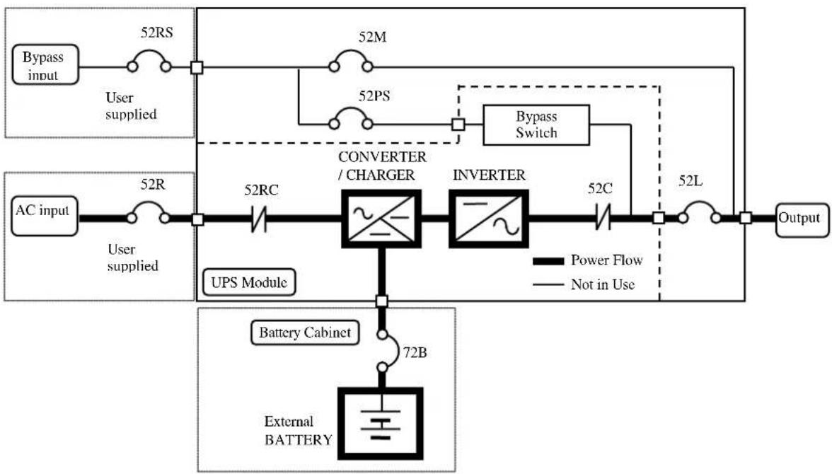
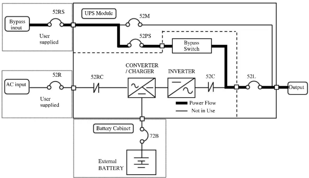
FIGURE 1.1 shows the path for normal operation, with the load powered from the inverter. FIGURE 1.2 shows the path for bypass operation, with the load supplied through the static bypass line.
A) Normal operation: Load power supplied by each system UPS inverter.
FIGURE 1.1 Single Line Diagram - Normal Operation: Load powered by UPS inverter
flowchart
graph LR
    A["Bypass input"] --> B["52RS"]
    B --> C["User supplied"]
    D["AC input"] --> E["52R"]
    E --> F["52RC"]
    F --> G["CONVERTER / CHARGER"]
    G --> H["INVERTER"]
    H --> I["52C"]
    I --> J["52L"]
    J --> K["Output"]
    L["Battery Cabinet"] --> M["External BATTERY"]
    M --> N["72B"]
    style A fill:#f9f,stroke:#333
    style D fill:#f9f,stroke:#333
    style L fill:#ccf,stroke:#333
    style M fill:#cfc,stroke:#333
    style N fill:#fcc,stroke:#333
    subgraph Power Flow
        G
        H
        I
        J
        K
    end
    subgraph Not in Use
        G
        H
        I
        J
        K
    end
During normal operation, the path through the UPS inverters is used to power the load.
Referring to FIGURE 1.1: Input AC power is converted to DC by the Converter. DC power is utilized to charge the UPS battery and to provide power to the Inverter. The Inverter converts the DC power to clean AC power to supply the critical load.
The conversion - inversion process eliminates any voltage transients or fluctuations existing in the input power before it reaches the critical load.
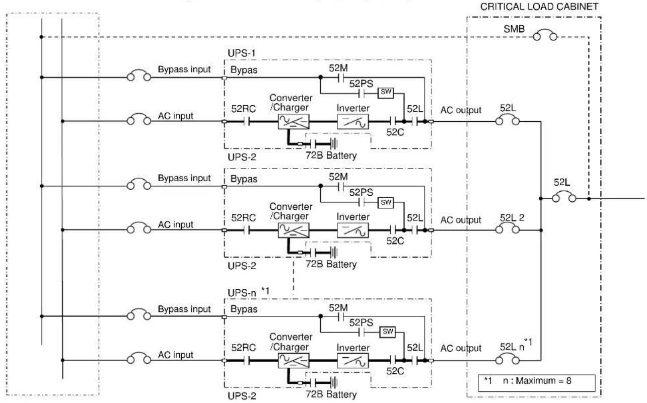
The power drawn by the critical load is equally shared between all UPS whenever the system is in the Parallel Operation. (Refer to FIGURE 3.4 that shows a sample of Parallel Operation System Configuration.)
In the event of a UPS module failure during Parallel Operation, the critical load power will be continually supplied and shared by all other UPS.

The Bypass Input circuit breaker (MCCB) for protection of the UPS and cables are field supplied and field installed. (See WARNING 4 on page 1-4)
B) Bypass Operation: Load Power supplied through UPS internal static bypass line.
FIGURE 1.2 Single Line Diagram - Bypass Operation: Load fed through static bypass line.
flowchart
graph LR
    A["Bypass input"] --> B["52RS"]
    B --> C["UPS Module"]
    C --> D["52M"]
    D --> E["52PS"]
    E --> F["Bypass Switch"]
    G["AC input"] --> H["52R"]
    H --> I["52RC"]
    I --> J["CONVERTER / CHARGER"]
    J --> K["INVERTER"]
    K --> L["52C"]
    L --> M["52L"]
    M --> N["Output"]
    O["Battery Cabinet"] --> P["72B"]
    P --> Q["External BATTERY"]
    style A fill:#f9f,stroke:#333
    style G fill:#f9f,stroke:#333
    style O fill:#f9f,stroke:#333
    style O fill:#ccf,stroke:#333
Referring to FIGURE 1.2: The Internal Bypass line is a Hard-wired line through bypass switch which supplies the critical load with unconditioned bypass input power. Upon switching to the Internal Bypass line, the bypass switch line through 52PS supplies the power immediately. In the event of a switching to the Bypass line, the power to the critical load will be uninterrupted. The purpose of this Internal Bypass line is to route power to the critical load while the UPS module is de-energized (converter and inverter), and during Start-up before the system is fully operational.
Each UPS internal static bypass line will equally share the power supplied to the critical load whenever the system is in the Parallel Operation.
In the event of a load overcurrent, the UPS transfers to bypass without interruption to the critical load. In the case of the Parallel Operation, all UPS will transfer to bypass without interruption to the critical load.
The internal control system determines the operation of the two paths, with the load powered from the inverter being the normal operation.
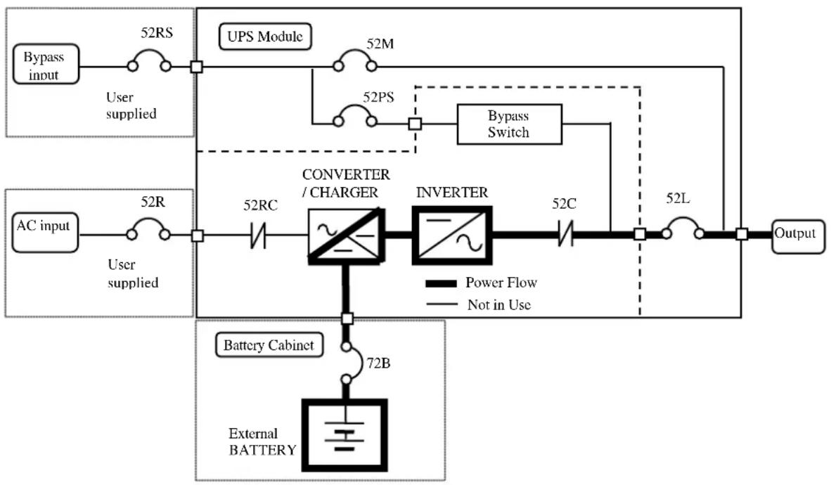
C) Battery operation: Load Power supplied by UPS battery.
FIGURE 1.3 Single Line Diagram - Battery Operation
flowchart
graph TD
    A["Bypass input"] --> B["52RS"]
    B --> C["UPS Module"]
    C --> D["52M"]
    D --> E["52PS"]
    E --> F["Bypass Switch"]
    G["AC input"] --> H["52R"]
    H --> I["CONVERTER / CHARGER"]
    I --> J["INVERTER"]
    J --> K["52C"]
    K --> L["52L"]
    L --> M["Output"]
    N["Battery Cabinet"] --> O["72B"]
    O --> P["External BATTERY"]
    style A fill:#f9f,stroke:#333
    style G fill:#f9f,stroke:#333
    style N fill:#ccf,stroke:#333
    style P fill:#cfc,stroke:#333
Referring to FIGURE 1.3: In the event of AC input source failure or interruption, the UPS Converter(s) ^ will de-energize and the UPS battery(s) ^ will immediately discharge and supply DC power to the Inverter to maintain continuous AC power to the load. This operation will continue until:
a) The battery capacity expires and the inverter turns off, or
b) Input power is restored after which the converter will power the inverter and critical load and simultaneously recharge the batteries.
A fully charged battery will provide power for the specified time at the rated load, or longer, at a reduced load.
(s)* : In the case of the Parallel Operation
When power is restored after a low battery shutdown, the UPS converter(s)* automatically restarts operation, the charger(s)* recharges the batteries and the Inverter(s)* is automatically restarted without operator intervention. Load is automatically assumed by the inverter without operator intervention.
(s)* : In the case of the Parallel Operation
The power drawn by the load is equally shared between all UPS regardless of the presence or absence of the UPS that is (are) in battery operation or not whenever the system is in the Parallel Operation.
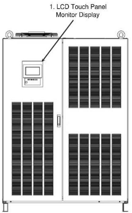
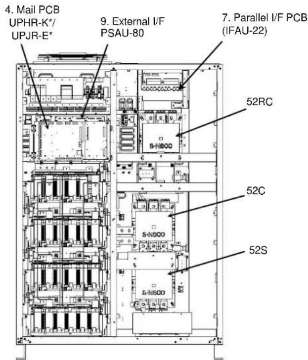
FIGURE 1.4.a UPS Parts Location (500,600kVA)
Front side
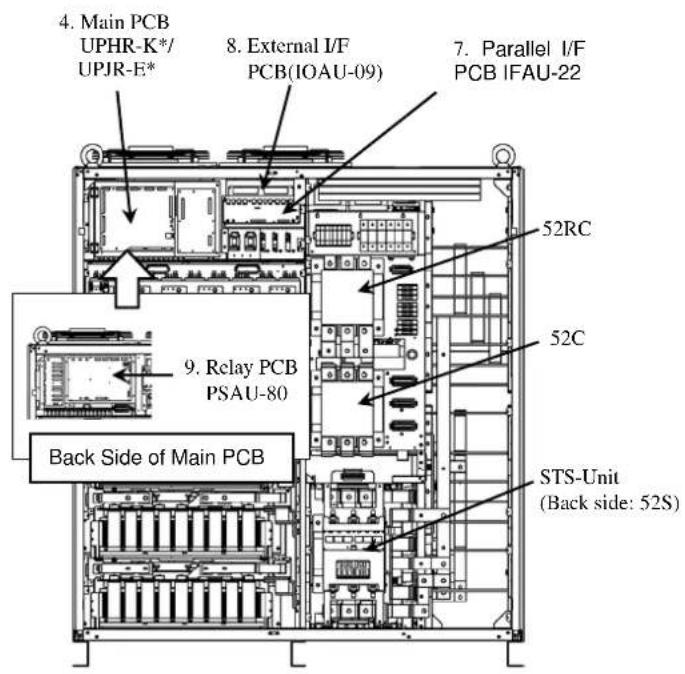
Inside
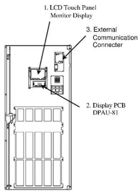
Inside of the Door
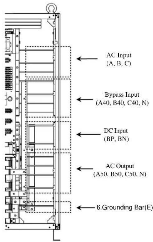
Cable entry
FIGURE 1.4.b UPS Parts Location (300,400kVA)
Front side
Inside
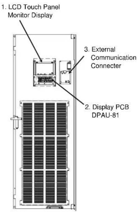
Inside of the Door
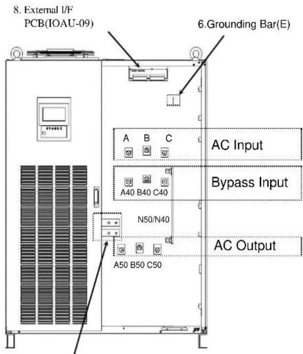
DC Input (BP,BN)
Cable entry
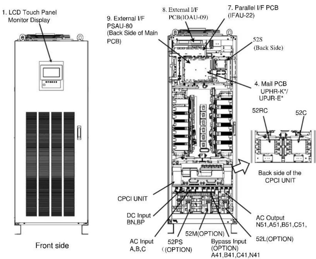
FIGURE 1.4.c UPS Parts Location (60, 120, 160, 200kVA)
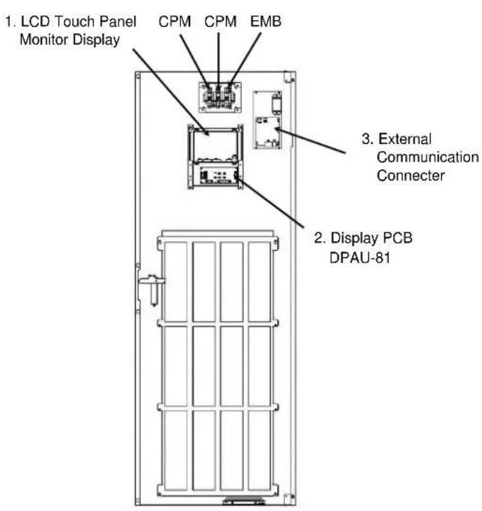
Inside of the Door
Inside
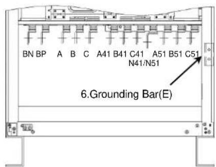
Cable entry
FIGURE 1.5 Display PCB DPAU-81
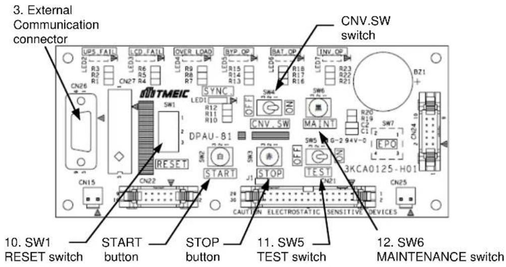
FIGURE 1.6 External I/F PCB IOAU-09
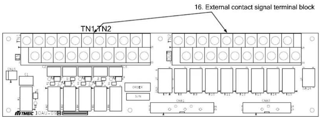
FIGURE 1.7 Parallel I/F PCB IFAU-22 (*Option of parallel system)
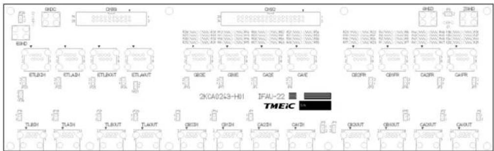
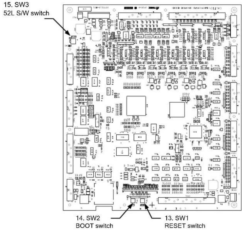
FIGURE 1.8 MAIN PCB
(a) UPHR-K*
(b) UPJR-E*
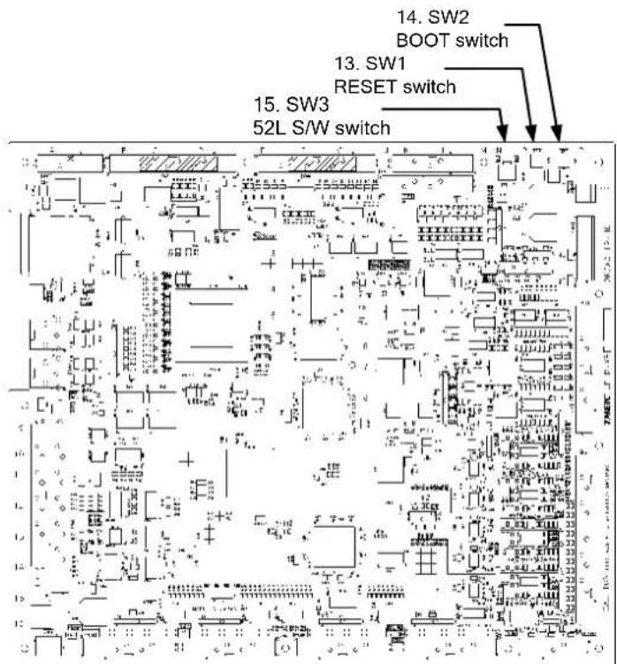
Description of FIGURES 1.4 to 1.8:
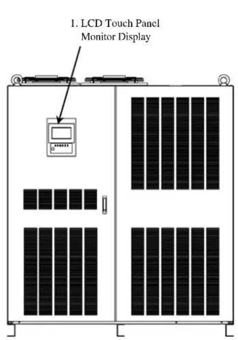
1. LCD Touch Panel Monitor Display
The Liquid Crystal Display (LCD) Touch Panel Monitor Display indicates power flow, measured values and fault and error messages via user selectable display screens. Refer to FIGURE 2.1 for details.
2. Display PCB DPAU-81 (FIGURE 1.5):
Switches on DPAU-81 board : FOR SERVICE PERSONNEL ONLY
- (10) SW1 (RESET switch)
- (11) SW5 (TEST switch)
- (12) SW6 (MAINTENANCE switch)
3. External Communication Connector
RS232C connector on DPAU-81 board : FOR SERVICE PERSONNEL ONLY
4. Main PCB UPHR-K\*/UPJR-E\* (FIGURE 1.8):
Switches on UPHR-K*/UPJR-E* board : FOR SERVICE PERSONNEL ONLY
- (13) SW1 (RESET switch)
- (14) SW2 (BOOT switch)
- (15) SW3 (52L S/W switch)
5. Parallel control PCB TLCR-H (not shown)
For use in Parallel Operation system application : Option
6. Grounding Bar (E)
Refer to FIGURE 3.2.
7. AC input, AC output, DC input terminal
Refer to FIGURE 3.2 for details.
8. External I/F PCB IOAU-09 (FIGURE 1.6):
Signal I/F on IOAU-09 board
- (16) External contact signal terminal block Refer to FIGURE 2.10 for details.
9. Power supply PCB PSAU-80
10. "RESET" switch (FOR SERVICE PERSONNEL ONLY)
This switch resets errors resulting from alarm conditions.
11. "TEST" switch (FOR SERVICE PERSONNEL ONLY)
This switch changes system operation to the test-mode.
12. "MAINTENANCE" switch (FOR SERVICE PERSONNEL ONLY)
This switch sets the UPS menu parameters.
13. "RESET" switch (FOR SERVICE PERSONNEL ONLY)
This switch resets errors resulting from alarm conditions.
14. "BOOT" switch (FOR SERVICE PERSONNEL ONLY)
This switch boots the processor on the main control circuit board following alarm conditions.
15. "52L S/W" switch (FOR SERVICE PERSONNEL ONLY)
This switch prohibits turning on the AC output contactor "52C" during test/maintenance in Parallel Operation system application.
16. External contact signal terminal block
Terminal block to connect contact signal input/output lines to and from external dry contacts. Refer to FIGURE 2.10 for details.
1.5 SYSTME SINGLE LINE DIAGRAM
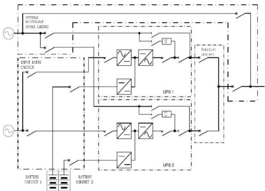
The UPS is apply to three types of systems as below
① Single module system with maintenance bypass
② Series backup redundancy system
③ Distributed bypass redundancy system
Using the different system to support the different requires. The UPS can be shut down for maintenance without cut the power in redundancy parallel system.
TABLE 1.3 System Diagram
| SYSTME | SYSTEM DIAGRAM |
| Single module system with maintenance bypass | 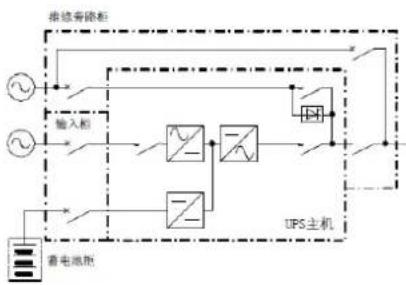 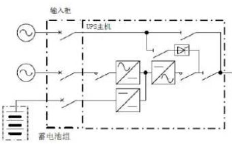 *External maintenance circuit cabinet is required with 300~600kVA UPS.200kVA UPS With internal maintenance bypass circuit (Option). *External maintenance circuit cabinet is required with 300~600kVA UPS.200kVA UPS With internal maintenance bypass circuit (Option). |
| Series backup redundancy system | 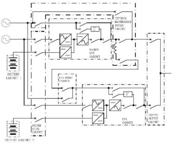 *.This system is required to add a reactor to the bypass circuit between main UPS and backup UPS.*.The internal switches 52PS and 52L keep connecting, and 52M keeps disconnecting during normal operation. Transfer load to external maintenance bypass to supply power during maintenance procedures. *.This system is required to add a reactor to the bypass circuit between main UPS and backup UPS.*.The internal switches 52PS and 52L keep connecting, and 52M keeps disconnecting during normal operation. Transfer load to external maintenance bypass to supply power during maintenance procedures. |
*.This system is required to add a reactor to the bypass circuit between main UPS and backup UPS.
*.The internal switches 52PS and 52L keep connecting, and 52M keeps disconnecting during normal operation. Transfer load to external maintenance bypass to supply power during maintenance procedures.
Distributed bypass redundancy system
flowchart
graph TD
    A["RETURN MULTIMOUNT SPASS CABINET"] --> B["INPUT ENTRY CABINET"]
    B --> C["UPS 1"]
    B --> D["UPS 2"]
    C --> E["Perlellie channel"]
    D --> F["BATTERY CABINET 1"]
    D --> G["BATTERY CABINET 2"]
    E --> H["Switch"]
    F --> I["Switch"]
    G --> J["Switch"]
    H --> K["Ground"]
    I --> L["Ground"]
    J --> M["Ground"]
*.Bypass input should be the same utility input. Otherwise, the cable of both bypass circuit must be the same in length.
*.Maximum units of parallel above to 8 UPSs.
*.The internal switches 52PS and 52L keep connecting, and 52M keeps disco nnecting during normal operation. Transfer load to external maintenance bypass to supply power during maintenance procedures.
The precautions for safety to operating the UPS
※1: Bypass Input/Maintenance Bypass Input/AC Input, all of them should to connect to the same 3 phase 4 wires Utility Input source.
※2: Refer to AC Input and Bypass Input (Maintenance Bypass) should be separated input power source, only bypass input source connect to ground, and the transformer of AC Input should be non-grounded.
※3: To prevent circuit unbalance occurred when providing power by bypass mode, to install a 1% reactor(Variability±1%) to AC Output for each UPS would be necessary in MMS system.
1.6 SPECIFICATIONS
The UPS nameplate displays the rated kVA as well as nominal voltages and currents. The nameplate is located on the inside of the UPS front door.
TABLE 1.4 Power Specifications
| Rated outputPower | Input voltage3 phase / 4 wire | Bypass input voltage3 phase / 4 wire | Output voltage3 phase / 4 wire |
| 60kVA/54kW, 120kVA/108kW | 380V | 380V | 380V |
| 160kVA/144kW, 200kVA/180kW | 380V | 380V | 380V |
| 300kVA/270kW, 400kVA/360kW | 380V | 380V | 380V |
| 500kVA/450kW, 600kVA/540kW | 380V | 380V | 380V |
TABLE 1.5 UPS Module Information
| UPS[kVA] | CableEntry | Width[in / mm] | Depth[in / mm] | Height[in / mm] | Weight[lb./ kg] | Heating[kcal/h] |
| 60120160200 | BOTTOM | 72.6 / 700 | 32.6 / 830 | 81.8 / 2080 | 1344.8/ 610 | 2060410055006900 |
| 300400 | BOTTOM/TOP | 55.1 / 1400 | 32.6 / 830 | 81.8 / 2080 | 2314.9 / 1050 | 1035013800 |
| 500600 | BOTTOM/TOP | 70.9/ 1800 | 32.6 / 830 | 81.8 / 2080 | 3637.6 / 1650 | 1545020600 |
TABLE 1.6 Detail of Specifications
| Rated Output kVA | 60 | 120 | 160 | 200 | 300 | 400 | 500 | 600 |
| Rated Output kW | 54 | 108 | 144 | 180 | 270 | 360 | 450 | 540 |
| AC INPUT | ||||||||
| Configuration | 3 phase, 4 wire | |||||||
| Voltage | 380V, 400V, 415V (+15% to -20%) | |||||||
| Frequency | 50 / 60 Hz (+/-10%) | |||||||
| Reflected Current THD | 8% max100% load | 5% max 100% load(no input filter required) | ||||||
| STATIC BYPASS INPUT | ||||||||
| Configuration | 3 phase, 4 wire | |||||||
| Voltage | 380V - 415V ±10% | |||||||
| Frequency | 50/60 Hz ±5% | |||||||
| BATTERY | ||||||||
| Nominal Voltage | 480 Vdc | |||||||
| Floating charge Voltage | 540 Vdc | |||||||
| Minimum Voltage | 400~540 Vdc | |||||||
| Number of Cells | 240 | |||||||
| AC OUTPUT | ||||||||
| Configuration | 3 phase, 4 wire | |||||||
| Voltage | 380V, 400V, 415V | |||||||
| Voltage Regulation | ±5% | |||||||
| Frequency | 50 / 60 Hz | |||||||
| Frequency Regulation | ±0.01 in free running mode | |||||||
| Power Factor | 0.9 lagging | |||||||
| Voltage THD | 2% maximum THD at 100% Linear Load5% maximum THD at 100% non-linear load*.±5% when load switched from inverter to bypass | |||||||
| Transient Response | ±2% maximum at 100% load step±2% maximum at loss/return of AC power±5% maximum at load transfer to/from static bypass | |||||||
| Transient Recovery | Less than 20ms | |||||||
| Voltage Unbalance | 2% maximum at 100% unbalanced load | |||||||
| Phase Displacement | ±1 deg. maximum at 100% load, ±3 deg. at unbalanced load | |||||||
| Inverter Overload | 125% for 10 minutes; 150% for 60 seconds at 25°C | |||||||
| ENVIRONMENTAL | ||||||||
| Cooling | Forced Air | |||||||
| Operating Temperature | 32°F to 104°F (0°C to 40°C).Recommended: 68 F to 86°F (20°C to 30°C) | |||||||
| Relative Humidity | 20% ~ 80% Non Condensing | |||||||
| Altitude | 1000 meter (3280feet) | |||||||
| Location | Indoor (free from corrosive gases and dust) | |||||||

MITSUBISHI ELECTRIC
M9950 SERIES UPS OWNERS / TECHNICAL MANUAL
Page Number: 1-22
TABLE 1.7 Rating of Contactors, Breaker and Fuses
| NUMBER APPLICATION | OUTPUT CAPACITY OF EQUIPMENT | |||||||||
| 60kVA | 120kVA | 160kVA | 200kVA | 300kVA | 400kVA | 500kVA | 600kVA | |||
| 54kW | 108kW | 144kW | 180kW | 270kW | 360kW | 450kW | 540kW | |||
| Contactor | 52RC | AC input contactor | 350A | 800A | 1000A | |||||
| 52C | Inverter output contactor | 350A 800A 1000A | ||||||||
| 88RC | Control circuit contactor | 20A | 20A | 20A | ||||||
| Breaker | 72B | Battery disconnect breaker (Recommended) | 600A | 1200A | 1600A | |||||
| User supply | AC input breaker (Recommended) | 400A 800A 1250A | ||||||||
| User supply | AC output breaker (Recommended) | 400A 800A 1250A | ||||||||
| User supply | AC Bypass breaker (Recommended) | 400A 800A 1250A | ||||||||
| Fuses | FPR-FPW FNR-FNW | DC fuse | — | 630A / 690V | 700A / 690V | |||||
| FP-FN | DC fuse | 400A / 690V | — | — | ||||||
| FRR1-FRT2 | AC input fuse | 450A / 690V | 900A / 550V | 800A / 690V *2P | ||||||
| FIU1-FIW2 | AC output fuse | 450A / 690V | 900A / 550V | 800A / 690V *2P | ||||||
| FPC-FNC | CHOP fuse | — | 800A/690V | 1250A / 600V | ||||||
| Disconnector (Optional) | 52M | AC maintenance switch | 400A | — | — | |||||
| 52PS | AC bypass switch | 400A | — | — | ||||||
| 52L | AC output switch | 400A | — | — | ||||||
*Rating would be changed.
2.0 OPERATION CONTROLS AND INDICATORS
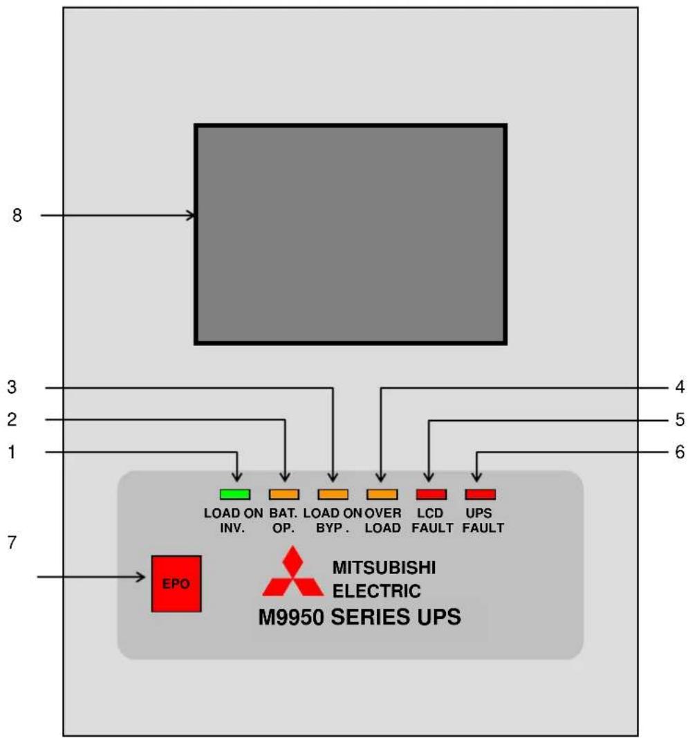
The M9950 Series operator controls and indicators are located as follows (Door exterior).
FIGURE 2.1 Operation/Display Panel (Front panel)
flowchart
graph TD
    A["Pin 8"] --> B["Block"]
    C["Pin 3"] --> D["LOAD ON INV."]
    E["Pin 2"] --> F["BAT. OP."]
    G["Pin 1"] --> H["LOAD ON BYP."]
    I["Pin 7"] --> J["LCD FAULT"]
    K["Pin 4"] --> L["UPS FAULT"]
    M["Pin 5"] --> N["UPS FAULT"]
    O["Pin 6"] --> P["MITSUBISHI ELECTRIC M9950 SERIES UPS"]
2.1 LED DISPLAY
1) Load on inverter LOAD ON INVERTER
Illuminates when power is supplied from inverter to the critical load.
(Indicates the state of inverter transfer switch "52C".)
2) Battery operation BATTERY OP.
Illuminates when power is supplied from batteries following a power failure.
3) Load on bypass LOAD ON BYPASS
Illuminates when power is supplied to load devices by static bypass.
(Indicates the state of bypass transfer switch "52S".)
4) Overload OVERLOAD
Illuminates in overload condition.
5) LCD fault [ LCD FAULT ] (red)
Illuminates when an error occurs.
6) UPS fault UPS FAULT [Annunciator: intermittent or constant tones]
Illuminates when an error occurs in the system. In this case, the details of the error are indicated on the display panel.
2.2 EPO BUTTON (Emergency Power Off button) (7)
When activated, the Emergency Power Off (EPO) function shuts down the UPS module. The critical load will lose power and also shutdown. The EPO function can be performed both locally or remotely.
2.3 LIQUID CRYSTAL DISPLAY (8)
The Liquid Crystal Display (LCD) touch panel indicates power flow, measured values, operational guidance, data records and error messages. The LCD panel has a back-light which facilitates viewing in different ambient lighting conditions. The LCD will automatically clear and turn off, if the screen is not activated within 3 minute period. The LCD is turned back on when it is touched again. The ERROR indicator is cleared after 24 hours and can be reproduced by pressing any key on the panel.
2.3.1 MENU
A) MAIN MENU (FIGURE 2.2)
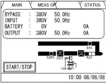
The LCD panel indicates power flow and measured values, while also operating the start/stop function. The LCD panel also allows the user to verify the status and operation of the UPS Module.
FIGURE 2.2.a Main screen (EN)
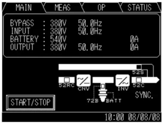
FIGURE 2.2.b Main screen (CN)
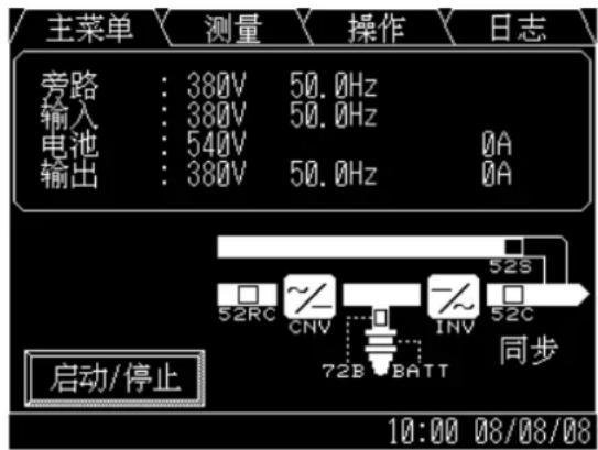
The following will be displayed when the START/STOP key on the MAIN MENU is pressed (Jump into OPERATION MENU):
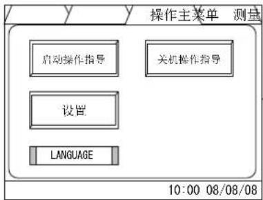
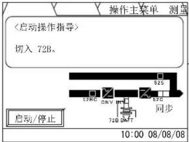
1) Startup/Shutdown Guidance (FIGURE 2.3)
The display indicates the Startup and Shutdown guidance for the UPS system. If this operation is PIN protected, the user is required to enter the security PIN before the screen can be accessed.
When in remote mode, the message “REMOTE operating model” will appear on this Screen. The user cannot operate the start and stop functions without changing the setup from remote mode to local mode.
When bypass voltage is abnormal, the message "Bypass voltage abnormal" will appear.
-Start: When the bypass voltage is abnormal, the LCD asks the operator if an interrupted transfer is acceptable (Load may be lost).
-Stop: When the bypass voltage is abnormal, the user cannot transfer from inverter to bypass line.
FIGURE 2.3-a Startup/Shutdown guidance(EN)
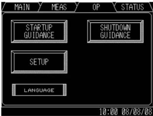
FIGURE 2.3-b Startup/Shutdown guidance(CN)
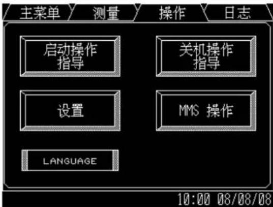
FIGURE 2.3-e Shutdown guidance(EN)
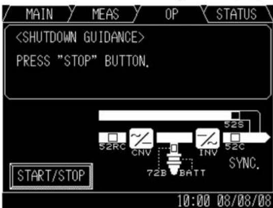
FIGURE 2.3-f Shutdown guidance()
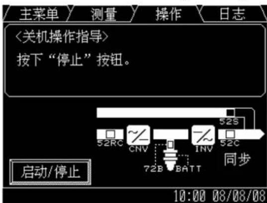
Follow Startup/Shutdown guidance accordingly.
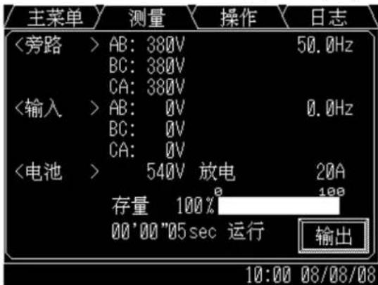
B) MEASUREMENT MENU (FIGURE 2.4)
This screen shows details of measured values. Input and Output values are displayed. During Battery operation, Remaining battery power and Run time are also displayed.
FIGURE 2.4-a Input values (EN)
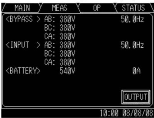
FIGURE 2.4-b Input values (CN)
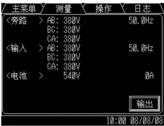
FIGURE 2.4-e Values in Battery operation(EN)
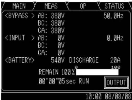
FIGURE 2.4-f Values in Battery operation(CN)
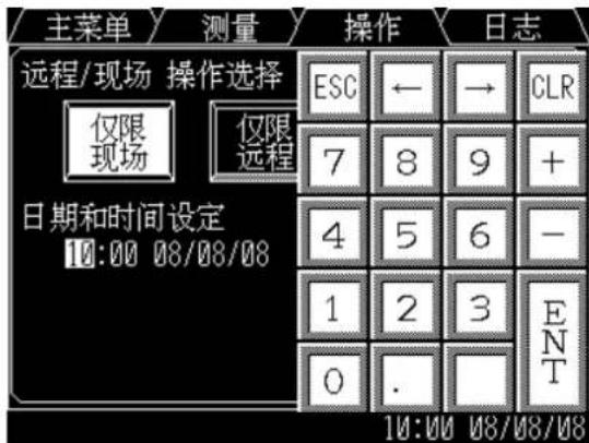
This screen prompts the user to select: (a) whether the start & stop operation will be performed by local or remote operation; (b) date & time adjustment; (c) battery equalizing charge. The battery equalizing charge operation key will appear when battery equalizing charge is set up (Setup is based on battery type).
FIGURE 2.5-a Remote/Local operation select(EN)
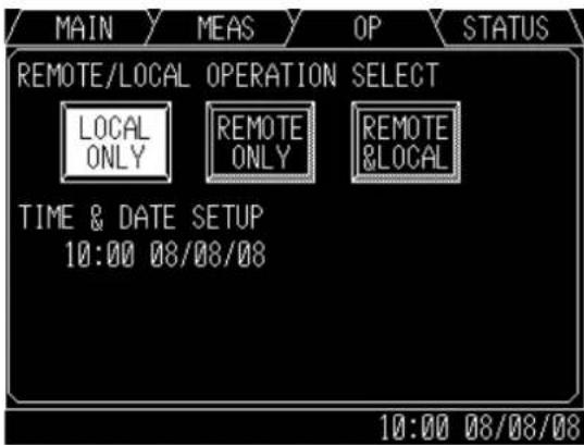
FIGURE 2.5-b Remote/Local operation select(CN)
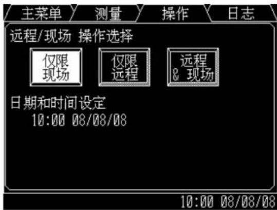
FIGURE 2.5-c Date & Time adjustment(EN)
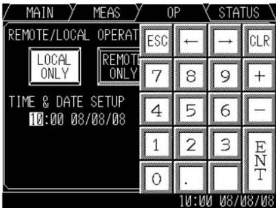
FIGURE 2.5-d Date & Time adjustment(CN)
This LOG MENU displays two Touch icons in EVENT LOG and BATTERY LOG.
Pressing the EVENT LOG icon, up to 50 condition/operation records will be displayed.
Press ▲ or ▼ button for page turning.
Pressing the BATTERY LOG icon, Number of battery operations and Summed battery operation time are displayed.
FIGURE 2.6-a Log menu(EN)
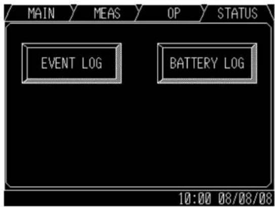
FIGURE 2.6-b Log menu(CN)
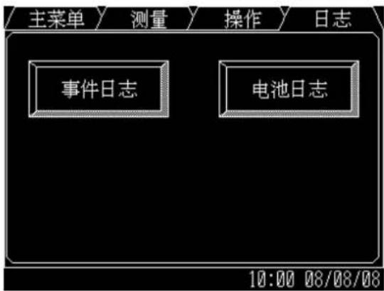
FIGURE 2.6-c Event log(EN)
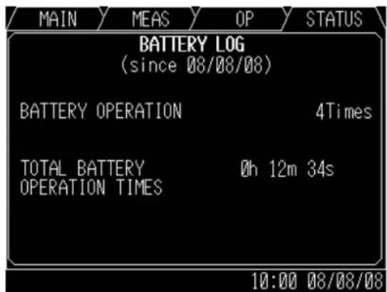
FIGURE 2.6-d Event log(CN)
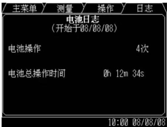
FIGURE 2.6-e Battery log(EN)
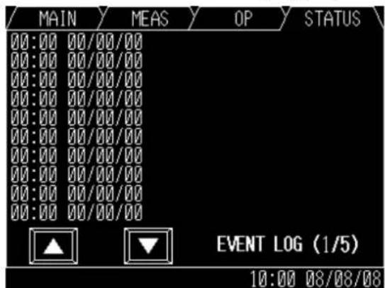
FIGURE 2.6-f Battery log(CN)
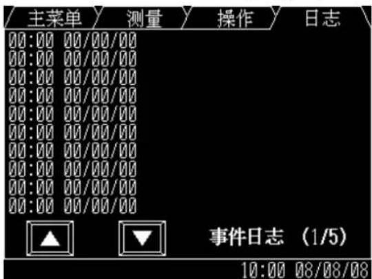
2.3.2 INPUT POWER FAILURE (FIGURE 2.7)
During an Input Power Failure, the UPS inverter will be powered by the UPS batteries. The following will be displayed on the main and measurement screen (Indication of battery operation and remaining battery life).
FIGURE 2.7-a Main screen(EN) (Battery operation)
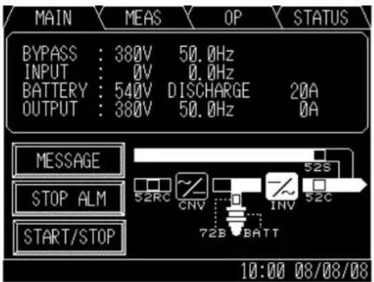
FIGURE 2.7-b Main screen(CN) (Battery operation)
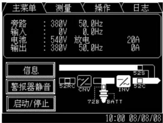
FIGURE 2.7-c Measurement screen(EN) (Battery operation)
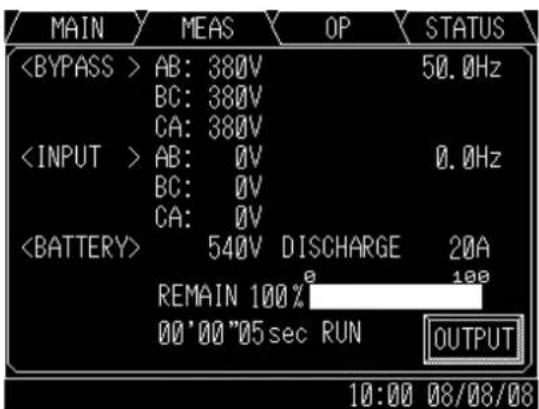
FIGURE 2.7-d Measurement screen(CN) (Battery operation)
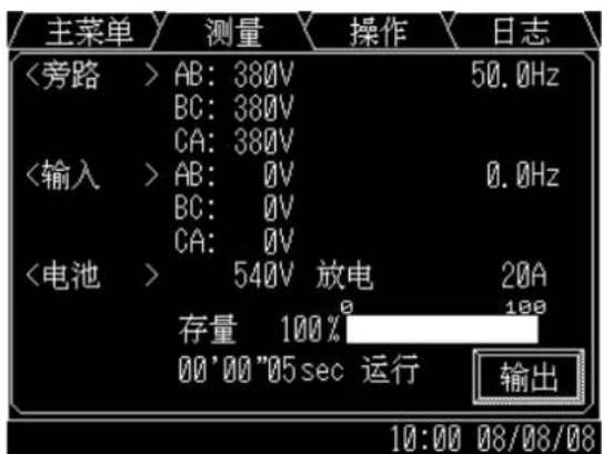
The LCD will display a battery low voltage message when the battery capacity is near depletion. The End of Battery Discharge announcement is displayed when the battery end voltage is reached. At this time, the inverter will perform an electronic shutdown to prevent battery loss of life typical from extreme deep discharge conditions. When the input power is restored, the inverter will automatically restart to power the load, and the batteries will be simultaneously recharged. The End of Battery announcement is shown at the bottom of the screen.
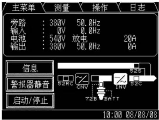
2.3.3 FAULT INDICATION (FIGURE 2.8)
“MESSAGE” and “STOP ALM” icons will appear on the main menu when UPS failure condition has occurred.
FIGURE 2.8-a Main screen (Fault indication)(EN)
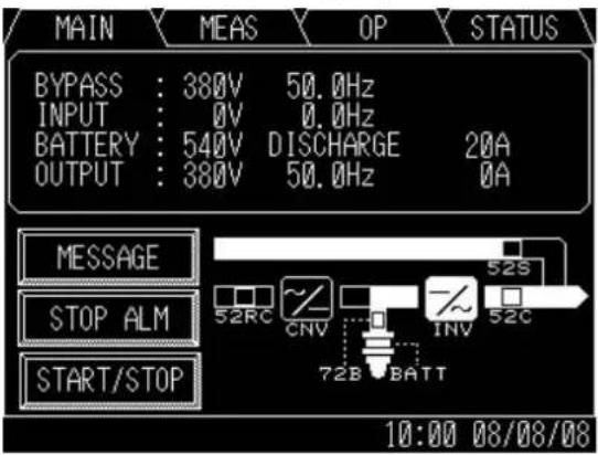
FIGURE 2.8-b Main screen (Fault indication)(CN)
The following will be displayed when the MESSAGE icon on the main menu is pressed.
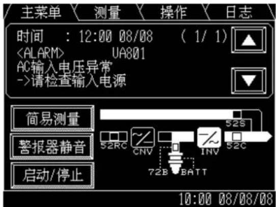
1) MESSAGE (FIGURE 2.9)
The display shows a fault code, the description of the fault and a guidance of what action is to be taken by the user. A maximum of 10 faults is displayed at one time. If an input power failure occurs during a fault condition, the fault indication and input power failure announcement are alternatively displayed at 5 second intervals.
FIGURE 2.9-a Message screen(EN)
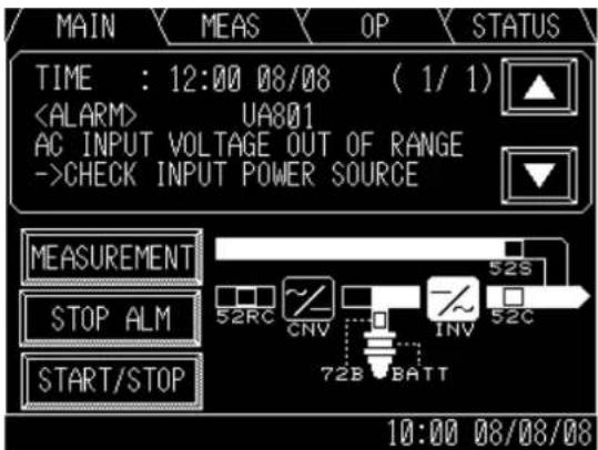
FIGURE 2.9-b Message screen(CN)
This icon "STOP ALM" will appear when a failure occurs. The audible alarm (announcing the failure) can be silenced by pressing this icon.
2.4 EXTERNAL SIGNAL TERMINAL BLOCK
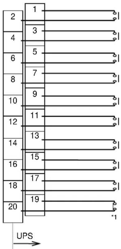
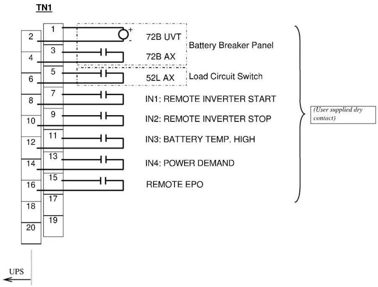
The UPS is equipped with a series of input/output terminals for external annunciation of alarms and for remote access of certain UPS functions. The layout of terminals is shown in FIGURE 2.10 with a functional description of the input/output port presented. OUT1 to OUT8 are user programmable, but are factory default set being also shown in FIGURE 2.10.
Adding same external I/F PCB "IOAU-09", doubling signal outputs is applicable for OUT1 to OUT8.
FIGURE 2.10-a External Signal Terminal Block (NEC Class2)
TN2
flowchart
graph TD
    A["1"] --> B["2"]
    A --> C["3"]
    A --> D["4"]
    A --> E["5"]
    A --> F["6"]
    A --> G["7"]
    A --> H["8"]
    A --> I["9"]
    A --> J["10"]
    A --> K["11"]
    A --> L["12"]
    A --> M["13"]
    A --> N["14"]
    A --> O["15"]
    A --> P["16"]
    A --> Q["17"]
    A --> R["18"]
    A --> S["19"]
    A --> T["20"]
    T --> U["*1"]
    V["UPS"] --> W
    style A fill:#f9f,stroke:#333
    style T fill:#f9f,stroke:#333
SUMMARY ALARM (Triggers on fault alarm only)
OUT1: LOAD ON BYPASS
OUT2: LOAD ON INVERTER
OUT8: TOTAL ALARM (Triggers on fault alarm only)
52C CLOSE
FIGURE 2.10-b External Signal Terminal Block (NEC Class2)
bar
| Pin | Number of Pins | |-----|----------------| | 1 | 72B UVT | | 2 | 3 | | 3 | 72B AX | | 4 | 5 | | 5 | 52L AX | | 6 | | | 7 | | | 8 | | | 9 | | | 10 | | | 11 | | | 12 | | | 13 | | | 14 | | | 15 | | | 16 | | | 17 | | | 18 | | | 19 | | | 20 | |A) Output Contacts (for external alarm annunciation)
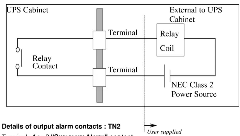
Output contacts consist of form “A” dry type contacts. Rated capacity of all output contacts is NEC Class2 (30Vdc/1Adc). All dry contacts should be operated at their rated values or lower. Figure 2.11 illustrates a typical installation. The external relay can also be a lamp, LED, computer, etc.
FIGURE 2.11 Control Wiring for External Contacts
flowchart
graph LR
    A["UPS Cabinet"] --> B["Relay Contact"]
    B --> C["Terminal"]
    C --> D["External to UPS Cabinet"]
    D --> E["Relay Coil"]
    E --> F["NEC Class 2 Power Source"]
    F --> G["Terminal"]
    G --> H["User supplied"]
Terminals 1 to 2 "Summary Alarm" contact
Activated when a major fault has occurred with the system.
Terminals 3 to 4 "Load on Bypass" contact (OUT1)
Activated when the power is supplied from the static bypass input.
Terminals 5 to 6 "Load on Inverter" contact (OUT2)
Activated when the power is supplied by the inverter.
Terminals 7 to 8 "Battery Operation" contact (OUT3)
Activated when the battery is operating following an AC power failure.
Terminals 9 to 10 "Converter Operation" contact (OUT4)
Activated when the converter is operating.
Terminals 11 to 12 "Battery Low Voltage" contact (OUT5)
Activated when the battery voltage drops below discharge end voltage level during inverter operation (i.e. During AC fail condition).
Terminals 13 to 14 "Overload" contact (OUT6)
Activated when an overload has occurred to the system.
Terminals 15 to 16 "Total Alarm" contact (OUT7)
Activated during major fault, minor fault and alarm events.
Terminals 17 to 18 "Spare" contact (OUT8)
Terminals 19 to 20 "52C Close" contact (OUT9)
Activated when the inverter output contactor 52C has closed.

The UPS is equipped with a selectable output contact feature. The above alarms are the default settings. Contact MITSUBISHI for setup information.
B) Input Contacts (for remote access of UPS)
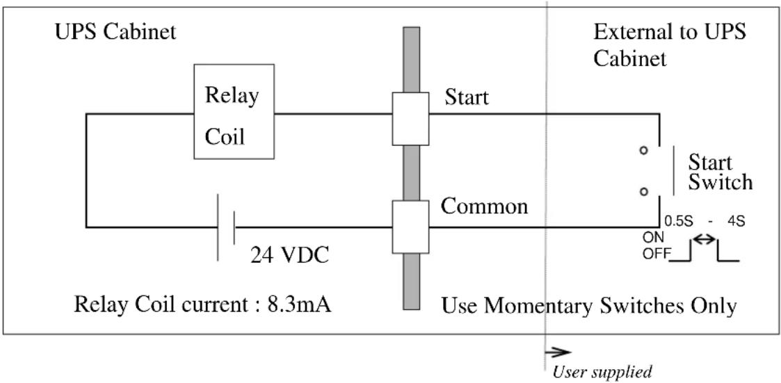
External contacts are provided by the user of the UPS system. Terminal voltage at the UPS is 24Vdc. Provide external dry contact accordingly.

Do not apply voltages to remote access input terminals. Damage to UPS may result.
Refer to FIGURE 2.12 for a typical wiring configuration. Although this figure applies to the remote start/stop terminals, the same wiring arrangement is used for emergency stop; power demand; and battery temperature high.
FIGURE 2.12 Remote "Start" Contact Connections
flowchart
graph TD
    A["Relay Coil"] --> B["24 VDC"]
    B --> C["Common"]
    C --> D["Start Switch"]
    D --> E["External to UPS Cabinet"]
    F["Relay Coil current: 8.3mA"] --> C
    G["Use Momentary Switches Only"] --> C
    H["User supplied"] --> G
Details of input contacts for remote access : TN1
Terminals 7 to 8 Remote "Inverter Start" input terminal (IN1)
Used to start inverter from a remote location. UPS must be programmed for remote operation. Refer to Operations Menu for procedure.
Terminals 9 to 10 Remote "Inverter Stop" input terminal (IN2)
Used to stop inverter from a remote location. UPS must be programmed for remote operation. Refer to Operations Menu for procedure.
Terminals 11 to 12 "Battery Temp. High" contact input (IN3)
Input fed by a thermocouple that monitors battery temperature. The converter float voltage level is reduced for battery over-temperature conditions. External thermocouple is user supplied
Terminals 13 to 14 "Power Demand" Command contact input (IN4)
This contact is used to control the input power. Power demand is turned ON when the contact is closed, and power demand is turned OFF when the contact is open.
Terminals 15 to 16 "Remote EPO" contact input
Used to perform a remote UPS Emergency Power Off (EPO).
The load will be dropped.

The UPS is equipped with a selectable input contact item.
The above items are the default settings.
Contact MITSUBISHI for setup information.

In all cases, a switch having a protective cover is recommended in order to reduce the possibility of accidental operation.
3.0 INSTALLATION AND OPERATION
3.1 TRANSPORTATION AND INSTALLATION
TABLE 3.1.1 How to transport and install the system
| Transportation Installation | |
| Transport unit with overhead crane or forklift. | Using the pre-drilled four holes in the UPS channel base, anchor the unit using appropriate hardware. (Not provided) |
If carry by overhead crane, use four eyebolts (Not provided)
TABLE 3.1.2 Transport by overhead crane
| Model | UPS Cabinet |
| 60, 120, 160, 200 kVA | 4 x M20 Lifting Eyes |
| 300,400 kVA | 4 x M24 Lifting Eyes |
| 500,600 kVA | 4 x M24 Lifting Eyes |
* Use lifting eyes on landing cabinet only to lift landing cabinet by itself, not as part of assembled unit.

PROHIBIT

NOTE
Do not transport UPS cabinet laid horizontally.
Cabinets must be maintained upright within +/- 15° of the vertical during handling.
3.2 INSTALLATION PROCEDURE
A) Note the load tolerance of the floor
Refer to TABLE 3.2 for list of UPS weights.
TABLE 3.2 List of UPS weights
| UPS Capacity (kVA) | 60 | 120 | 160 | 200 | 300 | 400 | 500 | 600 | ||
| Weight (kg.) | 610 | 1050 | 1650 | |||||||
B) Minimum clearance required for ventilation
Front side 1000 mm (39.4 inch) (for air flow)
Right side ____0 mm (0 inch)
Left side ____ 0 mm (0 inch)
Back side ....0 mm (0 inch)
Top side ____ 600 mm (23.6 inches) (for air flow)
C) Space requirement for routine maintenance
Allow for the following space at the time of installation.
Front 1000 mm (39.4 inches)
Sides ____ 0.0 mm (0 inch)
Back side 500mm (19.7 inch)
(Required for parts changes, also can be 0.0mm)
Top side ....600 mm (23.6 inches)
D) External Battery Supply
Please refer to the following when installing and maintaining batteries:

NOTE
- The customer shall refer to the battery manufacturer's installation manual for battery installation and maintenance instructions.
- The maximum permitted fault current from the remote battery supply.
3.3 PROCEDURE FOR CABLE CONNECTIONS \*
-
Confirm the capacity of the UPS being installed. Identify the input/output power terminal blocks as shown in the appropriate FIGURES 3.1 through 3.4.
-
Connect the internal control wire and power wire.
(1) Control wire Inter-connect
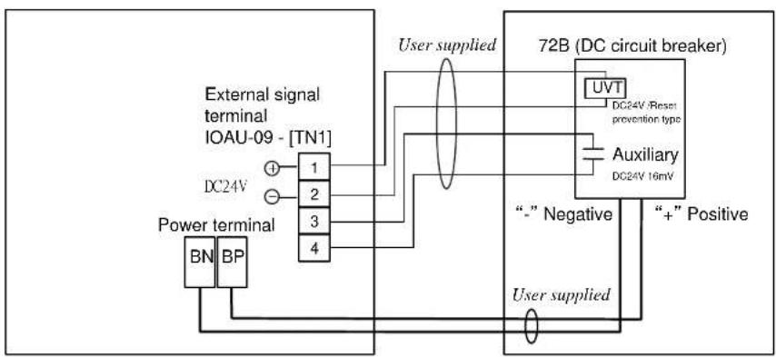
- 72B UVT to terminal TN1-1, 2 of external I/F PCB IOAU-09.
- 72B ON Auxiliary to terminal TN1-3, 4 of external I/F PCB IOAU-09.
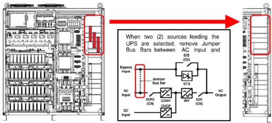
(2) Selection of one (1) source or two (2) sources feeding the UPS. When two (2) sources feeding the UPS is selected, remove Jumper BUS Bars between AC and Bypass Input (Fig. 3.4).
(3) Control wire Inter-connect
-
72B UVT to terminal TN1-1, 2 of external I/F PCB IOAU-09.
-
72B ON Auxiliary to terminal TN1-3, 4 of external I/F PCB IOAU-09.
(4) Power wire (AC input, Bypass input, AC output) Inter-connect
a.) From user's distribution panel
- X1 (A-phase) to A bus bar in UPS
- X2 (B-phase) to B bus bar in UPS
- X3 (C-phase) to C bus bar in UPS
- X4 (Neutral) to N bus bar in UPS
b.) DC Input to UPS
- Positive cable to BP bus bar in UPS
- Negative cable to BN bus bar in UPS

CAUTION : After the completion of the input power cables connection:
With a phase rotation meter, check that the phase rotation of the AC Input power terminals A, B and C as well as the Bypass Input power terminals A40, B40 and C40 are correct.
The proper phase rotation is clockwise A(R)
$$ \rightarrow \boldsymbol {B} (\mathsf {S}) \rightarrow \boldsymbol {C} (T). $$
- Connect the grounding conductor from the input service entrance to the UPS Ground Bar (E).

4. Two (2) sources feeding the UPS:
(1) Connect the AC input power cables from the input service entrance to the AC input power terminals, identified as A, B, C in FIGUREs 3.1 to 3.3. Input cables must be sized for an ampere rating larger than the maximum input drawn by the converter. (Refer to equipment nameplate for current ratings.) Confirm that an external bypass input circuit breaker (MCCB) is installed (refer to WARNING 4, page 1-4). Connect the bypass input power cables from the input service entrance to the bypass input power terminals, identified as A40, B40 and C40 in FIGUREs 3.1 to 3.3. Bypass input cables must be sized for an ampere rating larger than the maximum output current capacity of the UPS. Refer to TABLE 3.4 for recommended cable sizes.
(2) Connect the external signal terminal block as desired. Refer to section 2.4 and FIGURE 2.10 for functional description. 2mm^2 , or less, shielded conductor is recommended.
5. One (1) source feeding the UPS:
(1) Confirm that an external input circuit breaker sized to protect both the AC input and the bypass line is installed. (Refer to equipment nameplate for current ratings.) Connect the bypass input power cables from the input service entrance to the bypass input power terminals, identified as A40, B40 and C40 in FIGURES 3.1 to 3.3. Input cables must be sized for an ampere rating larger than the maximum current capacity of the UPS. Refer to TABLE 3.4 for recommended cable sizes.
(2) Using adequately sized conductors and referring to the appropriate figure identified in FIGURES 3.1 to 3.4, connect jumper bypass terminals A40, B40, C40 to AC input power terminals A, B, C as identified in FIGURES 3.1 to 3.4.
(3) Connect the external signal terminal block as desired. Refer to section 2.4 and FIGURE 2.10 for functional description. 2mm^2 , or less, shielded conductor is recommended.

- Confirm that all UPS internal contactors (breakers) "52RC", "52C" are open before energizing UPS.
- UPS power terminals are supplied with stud type fittings.
It is recommended that compression lugs be used to fasten all input/output power cables.
- Procedure for Cable Connections for Parallel Operation System
(1) Confirm the number of units to be connected in parallel. Identify the input/output power terminal blocks and control wire connections for parallel operation systems as shown in the appropriate FIGURES 3.5 and 3.6.
(2) Connect the external control wire and power wire.
a.) Control wire connection
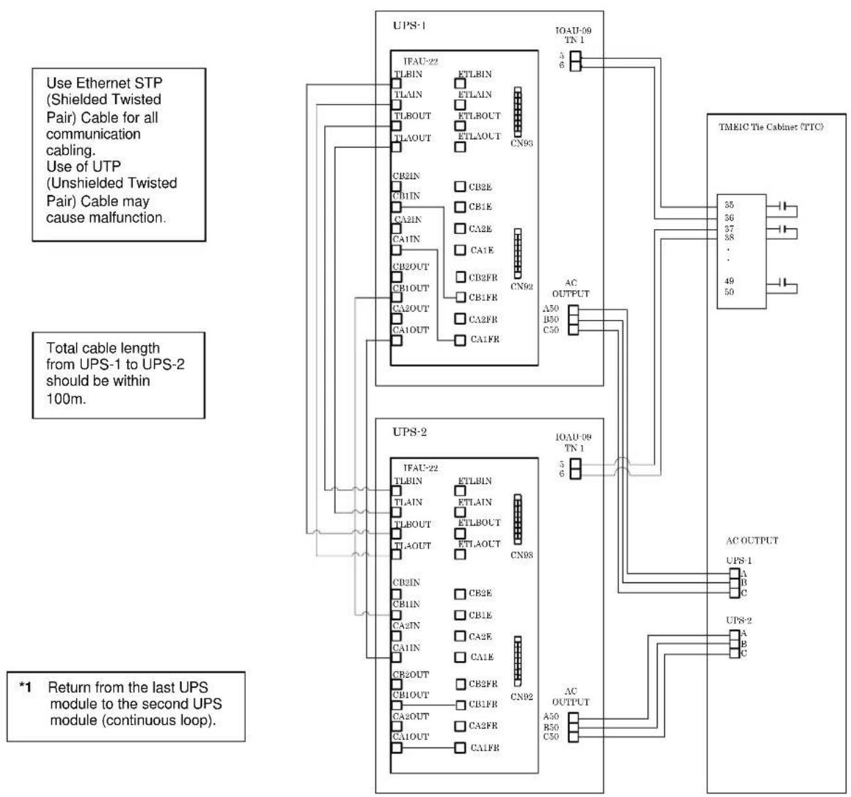
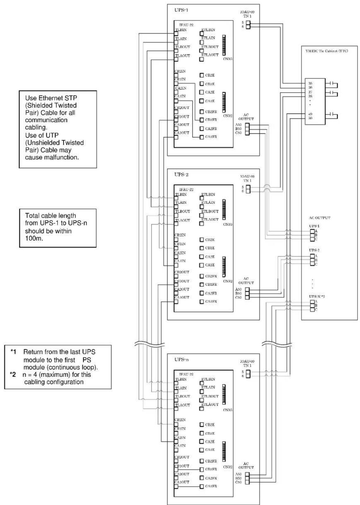
Parallel configuration wiring (Refer to FIGURE 3.5 and 3.6.)
- External 52L-n control signal from Critical Load Cabinet (CLC) to UPS-n IOAU-09 (TN1–5, 6).
- Parallel control signal for CN94 as shown in FIGURE 3.6.
- Parallel control signal for CN96 and CN95 as shown in FIGURE 3.6.
b.) Power wire connection
From UPS AC Output Terminals to Critical Load Cabinet (CLC) (Refer to FIGURE 3.5 and 3.6.)
3.4 RECOMMENDED CABLE SIZES
The cable sizes of AC Input, AC Output, Bypass Input, DC Input are shown in TABLE 3.3 to 3.5. Due to that many of different cable sizes used may course mistakes for installation, using the maximum size for design be recommended.
TABLE 3.3 Recommended Cable Sizes (AC Input)
| Capacity[kVA] | Cable size(MAX) | Screw size | Rated Current[A] |
| 60 2×70 mm | ^2 | M10 or M12 | 102 |
| 120 2×70 mm | ^2 205 | ||
| 160 2×70 mm | ^2 273 | ||
| 200 2×70 mm | ^2 341 | ||
| 300 2×120 mm | ^2 485 | ||
| 400 2×120 mm | ^2 646 | ||
| 500 2×240 mm | ^2 808 | ||
| 600 2×240 mm | ^2 969 |
TABLE 3.4 Recommended Cable Sizes (AC Output, Bypass Input)
| Capacity[kVA] | Cable size(MAX) | Screw size | Rated Current[A] |
| 60 2×70 mm | ^2 | M10 or M12 | 91 |
| 120 2×70 mm | ^2 182 | ||
| 160 2×70 mm | ^2 243 | ||
| 200 2×70 mm | ^2 304 | ||
| 300 2×120 mm | ^2 456 | ||
| 400 2×120 mm | ^2 608 | ||
| 500 2×240 mm | ^2 760 | ||
| 600 2×240 mm | ^2 912 |
TABLE 3.5 Recommended Cable Sizes (DC Connection)
| Capacity[kVA] | Cable size(MAX) | Screw size | Rated Current[A] |
| 60 2×95 mm | ^2 | M10 or M12 | 141 |
| 120 2×95 mm | ^2 281 | ||
| 160 2×95 mm | ^2 375 | ||
| 200 2×95 mm | ^2 470 | ||
| 300 2×185 mm | ^2 703 | ||
| 400 2×185 mm | ^2 938 | ||
| 500 4×150 mm | ^2 1172 | ||
| 600 4×150 mm | ^2 1406 |
*1 - The cables must be selected to be equal to the sizes listed in the table.
*2 - Voltage drop across power cables not to exceed 2% of nominal source voltage.
*3 - Allowable ampere-capacities based on 75 degree C. insulation at ambient temperature of 40 degree C.
Note: Copper conductors assumed.
FIGURE 3.1 UPS Terminal Designation
(60, 120, 160, 200kVA)
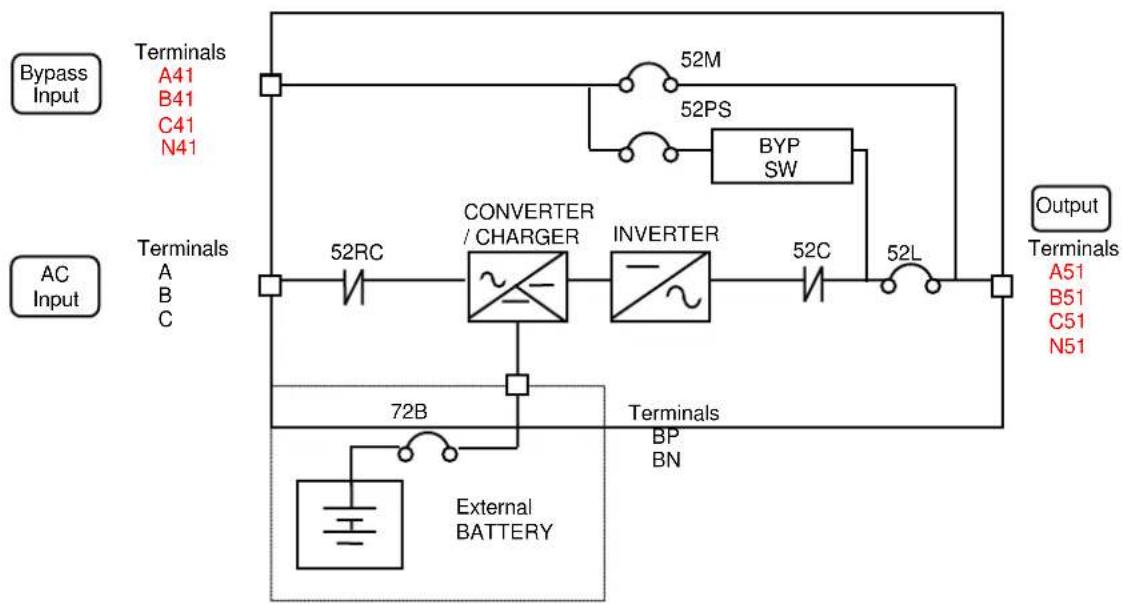
flowchart
graph TD
    A["AC Input"] --> B["Terminals A41 B41 C41 N41"]
    A --> C["Terminals A B C"]
    B --> D["52RC"]
    D --> E["CONVERTER / CHARGER"]
    E --> F["INVERTER"]
    F --> G["52C"]
    G --> H["52L"]
    H --> I["Output Terminals A51 B51 C51 N51"]
    J["Bypass Input"] --> K["Terminals A41 B41 C41 N41"]
    J --> L["Terminals A B C"]
    M["External BATTERY"] --> N["72B"]
    O["52M 52PS"] --> P["BYP SW"]
    Q["52C"] --> R["52L"]
(300\~600kVA)
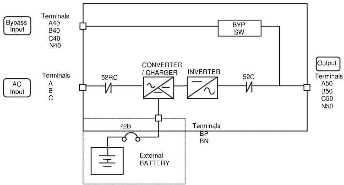
flowchart
graph TD
    A["AC Input"] --> B["Terminals A40 B40 C40 N40"]
    A --> C["Terminals A B C"]
    D["Bypass Input"] --> E["Terminals A40 B40 C40 N40"]
    F["CONVERTER / CHARGER"] --> G["INVERTER"]
    H["External BATTERY"] --> I["72B"]
    I --> J["Terminals BP BN"]
    K["BYP SW"] --> L["Output Terminals A50 B50 C50 N50"]

MITSUBISHI ELECTRIC
M9950 SERIES UPS OWNERS / TECHNICAL MANUAL
Page Number:
3-7
FIGURE 3.2.a Diagram of input/output bus bars and terminal blocks at one (1) source feeding the UPS (500,600kVA)
| Location of bus bars and terminal blocks (Top / Bottom Side Entry) | Detailed Power Terminals |
500, 600kVA : H:1980mm W:1800mm D:830mm※H: 2080(include Channel base)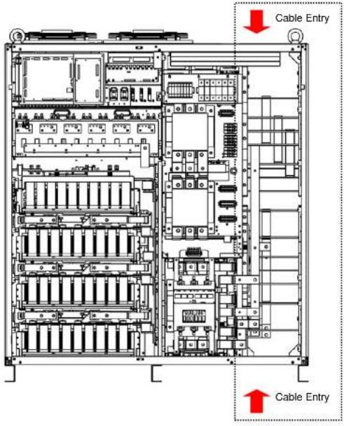 | For power terminals, use 1/2" (12mm) diameter bolts.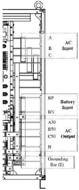 |

MITSUBISHI ELECTRIC
M9950 SERIES UPS OWNERS / TECHNICAL MANUAL
Page Number:
3-8
FIGURE 3.2.b Diagram of input/output bus bars and terminal blocks at two (2) source feeding the UPS (500,600kVA)
| Location of bus bars and terminal blocks (Top / Bottom Side Entry) | Detailed Power Terminals |
500,600kVA : H:1980mm W:1800mm D:830mm※H: 2080(include Channel base)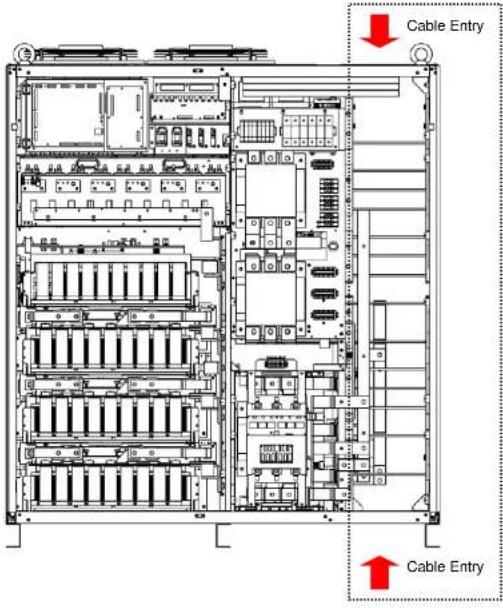 | For power terminals, use 1/2" (12mm) diameter bolts. |

MITSUBISHI ELECTRIC
M9950 SERIES UPS OWNERS / TECHNICAL MANUAL
Page Number: 3-9
FIGURE 3.2.c Diagram of input/output bus bars and terminal blocks (300,400kVA)
| Location of bus bars and terminal blocks (Top/Bottom Side Entry) | Detailed Power Terminals |
| 300,400kVA : H:1980mm W:1200mm D:830mm ※H: 2080(include Channel base) | For power terminals, use 1/2" (12mm) diameter bolts. |
| Cable Entry (Top) Grounding Bar (E) AC INPUT AC OUTPUT BYP INPUT A40340 C40 Cable Entry (Bottom) |

MITSUBISHI ELECTRIC
M9950 SERIES UPS OWNERS / TECHNICAL MANUAL
Page Number: 3-10
FIGURE 3.2.d Diagram of input/output bus bars and terminal blocks (200kVA)
| Location of bus bars and terminal blocks (Bottom Side Entry) | Detailed Power Terminals |
| 60, 120, 160, 200kVA : H:1980mm W:700mm D:830mm ※H: 2080(include Channel base) | For power terminals, use 1/2" (12mm) diameter bolts. |
| Cable Entry (Bottom) | Grounding Bar (E) |

MITSUBISHI ELECTRIC
M9950 SERIES UPS OWNERS / TECHNICAL MANUAL
Page Number: 3-11
FIGURE 3.3 Diagram of Power Wire & Control Wire Inter-Connect between UPS and Battery
flowchart
graph TD
    A["External signal terminal IOAU-09 - [TN1"]] -->|① DC24V| B["1"]
    A -->|②| C["2"]
    A -->|③| D["3"]
    A -->|④| E["4"]
    F["Power terminal"] --> G["BN"]
    F --> H["BP"]
    I["72B (DC circuit breaker)"] --> J["UVT DC24V /Reset prevention type"]
    J --> K["Auxiliary DC24V 16mV"]
    K --> L["“-” Negative"]
    K --> M["“+” Positive"]
    N["User supplied"] --> O["Ground"]
UPS module DC breaker for Battery
Note1)DC24V is outputted to 72B UVT coil through a terminal box from IOAU-09 PWB.
(DC24V power supply capability: maximum current 1.25A, rated current 0.41A)
If DC24V loses, the trip state of 72B will be carried out.
Note2) Even if a 72B UVT coil carries out reset operation of the breaker from a trip state in the state of no magnetizing, it cannot turn OFF.
Note3) When the magnetization voltage of a coil returns to 24V, it is possible to reset a breaker in the OFF state.
Note4)DC24V-16mA is impressed to 72B auxiliary contact through a terminal box from IOAU-09 PWB.
FIGURE 3.4.a Changing to two (2) source feeding the UPS from one (1) sources feeding the UPS at 200kVA
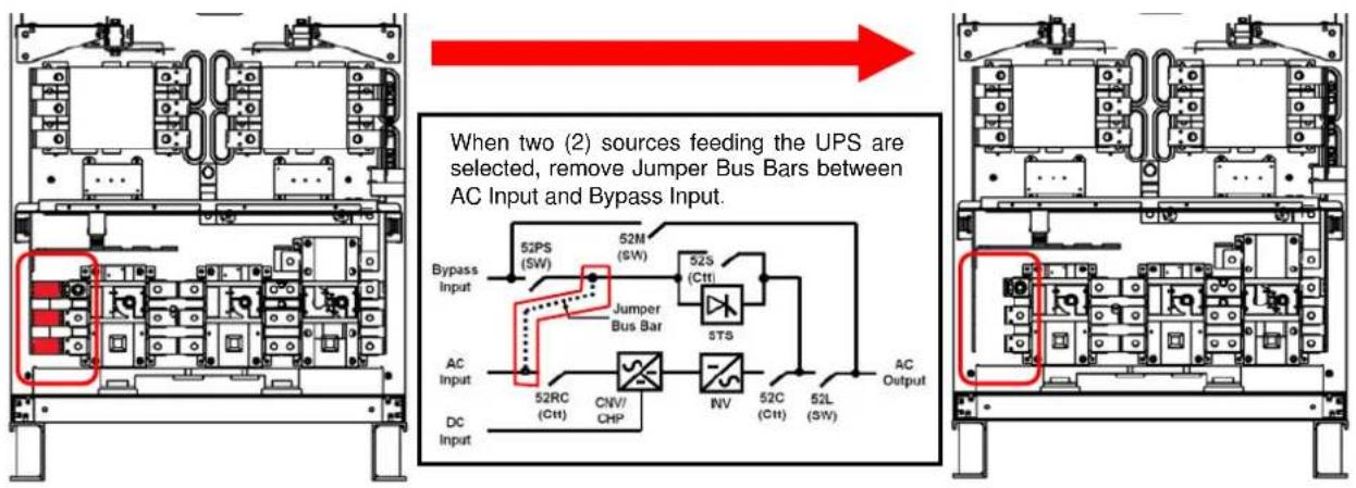
FIGURE 3.4.b Changing to two (2) source feeding the UPS from one (1) sources feeding the UPS at 300,400kVA
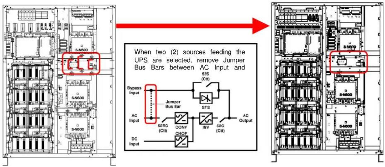
FIGURE 3.4.c Changing to two (2) source feeding the UPS from one (1) sources feeding the UPS at 500,600kVA

MITSUBISHI ELECTRIC
M9950 SERIES UPS OWNERS / TECHNICAL MANUAL
Page Number: 3-13
FIGURE 3.5 Diagram of Power Wire Connect (Parallel Operation system connection)
flowchart
graph TD
    subgraph UPS-1
        A1["52M"] --> B1["Converter /Charger"]
        B1 --> C1["Inverter"]
        C1 --> D1["52L"]
        D1 --> E1["AC output"]
        E1 --> F1["52L"]
        F1 --> G1["SMB"]
    end

    subgraph UPS-2
        A2["52RC"] --> B2["Converter /Charger"]
        B2 --> C2["Inverter"]
        C2 --> D2["52L"]
        D2 --> E2["AC output"]
        E2 --> F2["52L 2"]
        F2 --> G2["SMB"]
    end

    subgraph UPS-n
        A3["52M"] --> B3["Converter /Charger"]
        B3 --> C3["Inverter"]
        C3 --> D3["52L"]
        D3 --> E3["AC output"]
        E3 --> F3["52L n*1"]
    end

    subgraph UPS-2
        A4["52RC"] --> B4["Converter /Charger"]
        B4 --> C4["Inverter"]
        C4 --> D4["52L"]
        D4 --> E4["AC output"]
        E4 --> F4["52L n*1"]
    end

    style UPS-1 fill:#f9f,stroke:#333
    style UPS-2 fill:#ccf,stroke:#333
    style UPS-n fill:#cfc,stroke:#333
    style UPS-2 fill:#fcc,stroke:#333
    style UPS-n fill:#cff,stroke:#333
    note right of UPS-1: UPS-1 *1, Bypass input, AC input, UPS-2, UPS-n *1, AC input, Critical Load Cabinet *1 *n : Maximum = 8
MITSUBISHI ELECTRIC M9950 SERIES UPS
FIGURE 3.6.a Diagram of Power Wire & Control Wire Connections for 2 units in MMS Configuration
flowchart
graph TD
subgraph UPS-1
A["IFAU-22"] --> B["TLBIN"]
A --> C["TLAIN"]
A --> D["TLBOUT"]
A --> E["TLAOUT"]
A --> F["CB2IN"]
A --> G["CB1IN"]
A --> H["CA2IN"]
A --> I["CA1IN"]
A --> J["CB2OUT"]
A --> K["CB1OUT"]
A --> L["CA2OUT"]
A --> M["CA1OUT"]
A --> N["CA1FR"]
O["ETLBIN"] --> P["ETLAIN"]
O --> Q["ETLBOUT"]
O --> R["ETLAOUT"]
S["CB2E"] --> T["CB1E"]
U["CA2E"] --> V["CA1E"]
W["CB2FR"] --> X["CB1FR"]
Y["CA2FR"] --> Z["CA1FR"]
end
subgraph UPS-2
AA["IFAU-22"] --> AB["TLBIN"]
AA --> AC["TLAIN"]
AA --> AD["TLBOUT"]
AA --> AE["TLAOUT"]
AA --> AF["CB2IN"]
AA --> AG["CB1IN"]
AA --> AH["CA2IN"]
AA --> AI["CA1IN"]
AA --> AJ["CB2OUT"]
AA --> AK["CB1OUT"]
AA --> AL["CA2OUT"]
AA --> AM["CA1OUT"]
end
subgraph TMEIC Tie Cabinet (TTC)
AN["TMEIC Tie Cabinet (TTC)"] --> AO["35 36 37 38 49 50"]
end
note1["Use Ethernet STP (Shielded Twisted Pair) Cable for all communication cabling. Use of UTP (Unshielded Twisted Pair) Cable may cause malfunction."<br>Total cable length from UPS-1 to UPS-2 should be within 100m."<br>*1 Return from the last UPS module to the second UPS module (continuous loop)."<br> note2["AC OUTPUT"]
note3["AC OUTPUT"]
note4["A50 B50 C50"]
note5["5 6"]
note6["3 5"]
note7["5 6"]
note8["5 6"]
note9["5 6"]
note10["5 6"]
note11["5 6"]
note12["5 6"]
note13["5 6"]
note14["5 6"]
note15["5 6"]
note16["5 6"]
note17["5 6"]
note18["5 6"]
note19["5 6"]
note20["5 6"]
note21["5 6"]
note22["5 6"]
note23["5 6"]
note24["5 6"]
note25["5 6"]
note26["5 6"]
note27["5 6"]
note28["5 6"]
note29["5 6"]
note30["5 6"]
note31["5 6"]
note32["5 6"]
note33["5 6"]
note34["5 6"]
note35["5 6"]
note36["5 6"]
note37["5 6"]
note38["5 6"]
note39["5 6"]
note40["5 6"]
note41["5 6"]
note42["5 6"]
note43["5 6"]
note44["5 6"]
note45["5 6"]
note46["5 6"]
note47["5 6"]
note48["5 6"]
note49["5 6"]
note50["5 6"]
FIGURE 3.6.b Diagram of Power Wire & Control Wire Connections for 3 or 4 units in MMS Configuration
flowchart
graph TD
    A["UPS-1"] --> B["IFAU-22 TLBIN"]
    A --> C["ETLBIN"]
    A --> D["ETLAIN"]
    A --> E["TLBOUT"]
    A --> F["ETLBOUT"]
    A --> G["TLAOUT"]
    A --> H["ETLAOUT"]
    A --> I["CNS3"]
    A --> J["CE2IN"]
    A --> K["CB1IN"]
    A --> L["CA2IN"]
    A --> M["CA1IN"]
    A --> N["CE2OUT"]
    A --> O["CB1OUT"]
    A --> P["CA2OUT"]
    A --> Q["CA1OUT"]
    A --> R["CA2FR"]
    A --> S["CA1FR"]
    A --> T["CN92"]
    U["TMEIC Tie Cabinet (TTC)"] --> V["35 36 37 38 49 50"]
    V --> W["A50 B00 C00"]
    V --> X["AC OUTPUT"]
    Y["Total cable length from UPS-1 to UPS-n should be within 100m."] --> Z["IPS-2"]
    Z --> AA["IFAU-22 TLBIN"]
    Z --> AB["ETLBIN"]
    Z --> AC["ETLAIN"]
    Z --> AD["TLBOUT"]
    Z --> AE["ETLBOUT"]
    Z --> AF["TLAOUT"]
    Z --> AG["ETLAOUT"]
    Z --> AH["CNS3"]
    Z --> AI["CE2IN"]
    Z --> AJ["CB1IN"]
    Z --> AK["CA2IN"]
    Z --> AL["CA1IN"]
    Z --> AM["CE2OUT"]
    Z --> AN["CB1OUT"]
    Z --> AO["CA2OUT"]
    Z --> AP["CA1OUT"]
    Z --> AQ["CA2FR"]
    Z --> AR["CA1FR"]
    Z --> AS["CNS3"]
    Z --> AT["AC OUTPUT"]
    U --> AU["A50 B00 C00"]
    U --> AV["AC OUTPUT"]
    V --> AW["A50 B00 C00"]
    V --> AX["AC OUTPUT"]
    X --> AY["A50 B00 C00"]
    X --> AZ["AC OUTPUT"]
    Y --> BA["A50 B00 C00"]
    Y --> BB["AC OUTPUT"]
    Z --> BC["A50 B00 C00"]
    Z --> BD["AC OUTPUT"]
    AA --> BE["A50 B00 C00"]
    AA --> BF["AC OUTPUT"]
    AB --> BG["A50 B00 C00"]
    AB --> BH["AC OUTPUT"]
    AC --> BI["A50 B00 C00"]
    AC --> BJ["AC OUTPUT"]
    AD --> BK["A50 B00 C00"]
    AD --> BL["AC OUTPUT"]
    AE --> BM["A50 B00 C00"]
    AE --> BN["AC OUTPUT"]
    AF --> BO["A50 B00 C00"]
    AF --> BP["AC OUTPUT"]
    AG --> BQ["A50 B00 C00"]
    AG --> BR["AC OUTPUT"]
    AH --> BS["A50 B00 C00"]
    AH --> BT["AC OUTPUT"]
    AI --> BU["A50 B00 C00"]
    AI --> BV["AC OUTPUT"]
    AJ --> BW["A50 B00 C00"]
    AJ --> BX["AC OUTPUT"]
    AK --> BY["A50 B00 C00"]
    AK --> BZ["AC OUTPUT"]
FIGURE 3.6.c Diagram of Power Wire & Control Wire Connections for 5 to 8 units in MMS Configuration
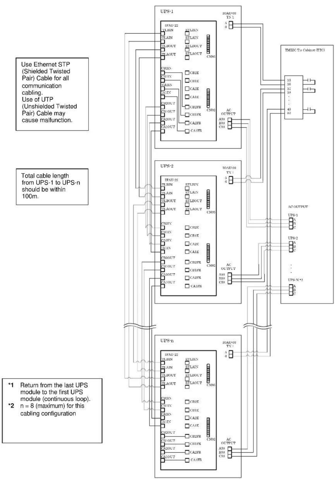
flowchart
graph TD
    subgraph UPS-1
        A["TPAU-22 TLBIN"] --> B["ETLBIN"]
        C["TLAIN"] --> D["ETLAIN"]
        E["TLBOUT"] --> F["ETLBOUT"]
        G["TLAOUT"] --> H["ETLAOUT"]
        I["CB2IN"] --> J["CB2E"]
        K["C81IN"] --> L["C81E"]
        M["C83IN"] --> N["CA2E"]
        O["C84IN"] --> P["CA1E"]
        Q["C82OUT"] --> R["CB2PR"]
        S["C81OUT"] --> T["C81PR"]
        U["C82OUT"] --> V["CA2PR"]
        W["C83OUT"] --> X["CA1FR"]
    end

    subgraph UPS-2
        Y["TPAU-23 TLBIN"] --> Z["ETLBIN"]
        AA["TLAIN"] --> AB["ETLAIN"]
        AC["TLBOUT"] --> AD["ETLBOUT"]
        AE["TLAOUT"] --> AF["ETLAOUT"]
        AG["C82IN"] --> AH["CB2E"]
        AI["C83IN"] --> AJ["CB1E"]
        AK["C83IN"] --> AL["CA2E"]
        AM["C84IN"] --> AN["CA1E"]
        AO["C85OUT"] --> AP["CB2PR"]
        AQ["C81OUT"] --> AR["CB1PR"]
        AS["C82OUT"] --> AT["CA2PR"]
        AU["C83OUT"] --> AV["CA1FR"]
    end

    subgraph UPS-n
        AW["TPAU-22 TLBIN"] --> AX["ETLBIN"]
        AY["TLAIN"] --> AZ["ETLAIN"]
        BA["TLBOUT"] --> BB["ETLBOUT"]
        BC["TLAOUT"] --> BD["ETLAOUT"]
        BE["C82IN"] --> BF["CB2E"]
        BG["C83IN"] --> BH["CB1E"]
        BI["C83IN"] --> BJ["CA2E"]
        BK["C84IN"] --> BL["CA1E"]
        BM["C82OUT"] --> BN["CB2PR"]
        BO["C81OUT"] --> BP["CB1PR"]
        BQ["C82OUT"] --> BR["CA2PR"]
        BS["C83OUT"] --> BT["CA1FR"]
    end

    UPS-1 -->|IOAU-09 TN 1| TMEIC_Tie_Cabinet(TTC)
    UPS-2 -->|AC OUTPUT| TMEIC_Tie_Cabinet(TTC)
    UPS-n -->|IOAU-09 TN 1| TMEIC_Tie_Cabinet(TTC)
    TMEIC_Tie_Cabinet(TTC) -->|33 36 57 58 49 60| UPS-1
    TMEIC_Tie_Cabinet(TTC) -->|APS-2 A B C ... UPS-N*2 A B C| UPS-1
    TMEIC_Tie_Cabinet(TTC) -->|APS-2 A B C ... UPS-N*2 A B C| UPS-1
    TMEIC_Tie_Cabinet(TTC) -->|APS-2 A B C ... UPS-N*2 A B C| UPS-1
    TMEIC_Tie_Cabinet(TTC) -->|APS-2 A B C ... UPS-N*2 A B C| UPS-2
    TMEIC_Tie_Cabinet(TTC) -->|APS-2 A B C ... UPS-N*2 A B C| UPS-2
    TMEIC_Tie_Cabinet(TTC) -->|APS-2 A B C ... UPS-N*2 A B C| UPS-3
    TMEIC_Tie_Cabinet(TTC) -->|APS-2 A B C ... UPS-N*2 A B C| UPS-3
    TMEIC_Tie_Cabinet(TTC) -->|APS-2 A B C ... UPS-N*2 A B C| UPS-3
    TMEIC_Tie_Cabinet(TTC) -->|APS-2 A B C ... UPS-N*2 A B C| UPS-4
    TMEIC_Tie_Cabinet(TTC) -->|APS-2 A B C ... UPS-N*2 A B C| UPS-4
    TMEIC_Tie_Cabinet(TTC) -->|APS-2 A B C ... UPS-N*2 A B C| UPS-5
    TMEIC_Tie_Cabinet(TTC) -->|APS-2 A B C ... UPS-N*2 A B C| UPS-5
    TMEIC_Tie_Cabinet(TTC) -->|APS-2 A B C ... UPS-N*2 A B C| UPS-6
    TMEIC_Tie_Cabinet(TTC) -->|APS-2 A B C ... UPS-N*2 A B C| UPS-6
    TMEIC_Tie_Cabinet(TTC) -->|APS-2 A B C ... UPS-N*2 A B C| UPS-7
    TMEIC_Tie_Cabinet(TTC) -->|APS-2 A B C ... UPS-N*2 A B C| UPS-7
    TMEIC_Tie_Cabinet(TTC) -->|APS-2 A B C ... UPS-N*2 A B C| UPS-8
    TMEIC_Tie_Cabinet(TTC) -->|APS-2 A B C ... UPS-N*2 A B C| UPS-8
    TMEIC_Tie_Cabinet(TTC) -->|APS-2 A B C ... UPS-N*2 A B C| UPS-9
    TMEIC_Tie_Cabinet(TTC) -->|APS-2 A B C ... UPS-N*2 A B C| UPS-9
    TMEIC_Tie_Cabinet(TTC) -->|APS-2 A B C ... UPS-N*2 A B C| UPS-10
    TMEIC_Tie_Cabinet(TTC) -->|APS-2 A B C ... UPS-N*2 A B C| UPS-10
    TMEIC_Tie_Cabinet(TTC) -->|APS-2 A B C ... UPS-N*2 A B C| UPS-11
    TMEIC_Tie_Cabinet(TTC) -->|APS-2 A B C ... UPS-N*2 A B C| UPS-11
    TMEIC_Tie_Cabinet(TTC) -->|APS-2 A B C ... UPS-N*2 A B C| UPS-12
    TMEIC_Tie_Cabinet(TTC) -->|APS-2 A B C ... UPS-N*2 A B C| UPS-12
    TMEIC_Tie_Cabinet(TTC) -->|APS-2 A B C ... UPS-N*2 A B C| UPS-13
    TMEIC_Tie_Cabinet(TTC) -->|APS-2 A B C ... UPS-N*2 A B C| UPS-13
    TMEIC_Tie_Cabinet(TTC) -->|APS-2 A B C ... UPS-N*2 A B C| UPS-14
    TMEIC_Tie_Cabinet(TTC) -->|APS-2 A B C ... UPS-N*2 A B C| UPS-14
    TMEIC_Tie_Cabinet(TTC) -->|APS-2 A B C ... UPS-N*2 A B C| UPS-15
    TMEIC_Tie_Cabinet(TTC) -->|APS-2 A B C ... UPS-N*2 A B C| UPS-15
    TMEIC_Tie_Cabinet(TTC) -->|APS-2 A B C ... UPS-N*2 A B C| UPS-16
    TMEIC_Tie_Cabinet(TTC) -->|APS-2 A B C ... UPS-N*2 A B C| UPS-16
    TMEIC_Tie_Cabinet(TTC) -->|APS-2 A B C ... UPS-N*2 A B C| UPS-17
    TMEIC_Tie_Cabinet(TTC) -->|APS-2 A B C ... UPS-N*2 A B C| UPS-17
    TMEIC_Tie_Cabinet(TTC) -->|APS-2 A B C ... UPS-N*2 A B C| UPS-18
    TMEIC_Tie_Cabinet(TTC) -->|APS-2 A B C ... UPS-N*2 A B C| UPS-18
    TMEIC_Tie_Cabinet(TTC) -->|APS-2 A B C ... UPS-N*2 A B C| UPS-19
    TMEIC_Tie_Cabinet(TTC) -->|APS-2 A B C ... UPS-N*2 A B C| UPS-19
    TMEIC_Tie_Cabinet(TTC) -->|APS-2 A B C ... UPS-N*2 A B C| UPS-100
3.5 OPERATING PROCEDURES
The operation procedures are described by the symbols below.
Although the operation of "UPS supply" "bypass supply" might be different in each system which depends on user's requirements, please consult the exclusive manual for each system in order to ensure proper operation.
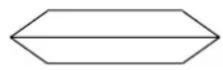
: Manual Operation
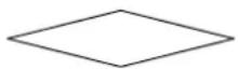
: Selection Item
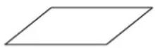
: Automatic Operation / Device Status
: Power Status
For parallel operation system of MMS (Multi-Module System), refer to section "3.5.2 Start-up / Shut-down (MMS with Individual Bypass Parallel Redundancy)".

NOTE
Before the UPS startup, the internal Bypass line starts to supply the unconditioned bypass input power to the critical load if the External input (or Bypass) Circuit Breaker is closed. Be extremely careful with closing the External input (or Bypass) Circuit Breaker. Confirm the position of the circuit protectors (CPMC, CPMS and EMB) located at the upper part of the cabinet (FIGURE 3.7).
1) CPMC and CPMS: ON; 2) EMB: OFF.
FIGURE 3.7 Circuit protectors location
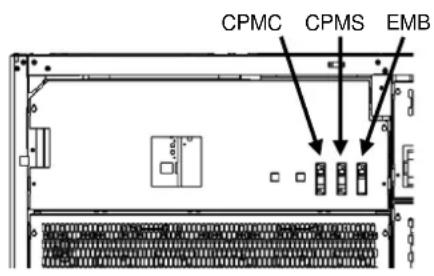
500,600kVA
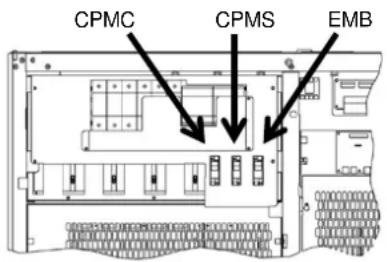
300, 400kVA
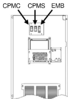
60, 120, 160, 200kVA
3.5.1 Start-up/Shut-down Procedure (Single Module System)
The single-line diagram of single module system is shown in FIGURE 3.8.
FIGURE 3.8 Circuit diagram of single module system
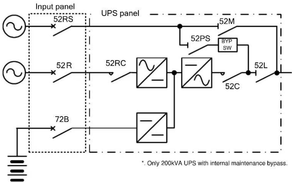
flowchart
graph TD
    A["Input panel"] --> B["52RS"]
    C["Input panel"] --> D["52R"]
    E["72B"] --> F["72RC"]
    G["UPS panel"] --> H["52PS"]
    H --> I["52M"]
    I --> J["52L"]
    J --> K["52C"]
    K --> L["BYP SW"]
    L --> M["Ground"]
    style A fill:#f9f,stroke:#333
    style C fill:#f9f,stroke:#333
    style E fill:#f9f,stroke:#333
    style G fill:#f9f,stroke:#333
    style J fill:#f9f,stroke:#333
    note right of A: Only 200kVA UPS with internal maintenance bypass.
    note right of J: * Only 200kVA UPS with internal maintenance bypass.
In this section, the operation started with the status in "Bypass Supply Mode". (Confirm all of the switches is opened or in tripping position besides 52MB.)

When "REMOTE OPERATION MODE" is displayed on the touch screen, the inverter start operation can only be performed remotely. If local inverter start operation is required (at the UPS), select "LOCAL ONLY" or "REMOTE & LOCAL" in the OPERATION MENU.
- Start-up Procedure (Single Module System)
| Device | Touch Screen Flowchart of Start-up Operation Load status | |||
| Load | Confirm the loads had turned OFF | OUTAGE | ||
| UPS Panel | Confirm input switch 52PS is closed. Confirm output switch 52L is opened. Confirm maintenance bypass switch 52M is opend. | |||
| Input Panel | When external bypass breaker turns to "ON", the status of power supply will be shown on the MAIN screen. Due to the status of input breaker "52R" is "OFF", the message "Warning"(UA801) will be detected. Please follow the next indication for operation. | External Bypass Breaker (52RS) Manual ON | ||
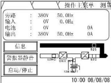 | ||||
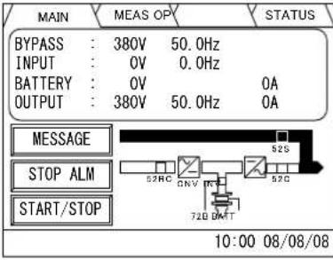 | ||||
| Input Panel | 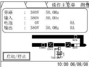 | External input breaker (52R) Manual ON | ||
| Input contactor (52RC) Automatic ON | ||||
 | Converter Automatic Start-up | |||
| Inverter Automatic Start-up | ||||
| After turning external input breaker (52R) "ON", the status of "Alarm" will be deactivated. | ||||
| Device | Touch Screen Flowchart of Start-up Operation Load status | ||
| UPS Panel | H志 | Touch ScreenPress「操作」or「OP」 | (OUTAGE) |
 | |||
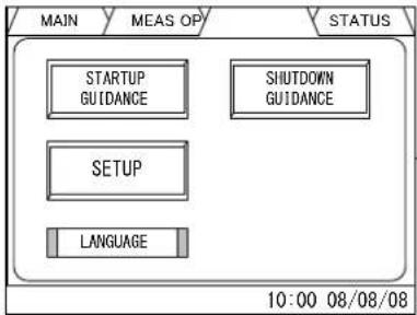 | |||
| 日志 | Touch ScreenPress「启动操作指导」or「STARTUP GUIDANCE」 | ||
 | |||
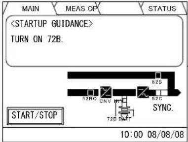 | |||
| When inverter output voltage and bypass voltage are synchronized, the message "SYNC." or "同步" will be shown on screen. | |||
| Device Touch Screen Flowchart of Start-up Operation Load status | ||||
| Input Panel | H芯 | (OUTAGE) | ||
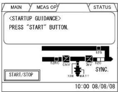
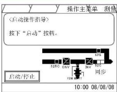 | 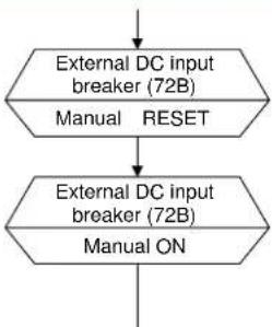 | |||
 |  | |||
| UPS Panel | Maintenance bypass switch (52M)OFF confirm | Load on Bypass | ||
| Output switch (52L)Manual ON | ||||
| UPS Panel | WGHW | 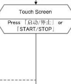 | ||
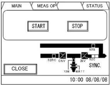 | ||||
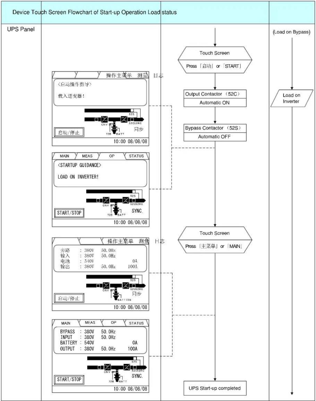
flowchart
graph TD
    A["Device Touch Screen Flowchart of Start-up Operation Load status"] --> B["UPS Panel"]
    B --> C["操作主菜单 测量"]
    C --> D{启动操作指导}
    D -->|是| E["载入逆变器!"]
    E --> F["启动/停止"]
    F --> G["10:00 08/08/08"]
    G --> H["操作主菜单 测量"]
    H --> I{START/STOP}
    I -->|是| J["LOAD ON INVERTER!"]
    J --> K["START/STOP"]
    K --> L["10:00 08/08/08"]
    L --> M{操作主菜单 测量}
    M -->|是| N["旁路:380V 50.0Hz"]
    M -->|否| O["输入:380V 50.0Hz"]
    M --> P["电池:540V 0A"]
    M --> Q["输出:380V 50.0Hz 100A"]
    M --> R["启动/停止"]
    R --> S["10:00 08/08/08"]
    S --> T["操作主菜单 测量"]
    T --> U{START/STOP}
    U -->|是| V["START/STOP"]
    U -->|否| W["UPS Start-up completed"]
    W --> X["UPS Start-up completed"]
    X --> Y["(Load on Bypass)"]
    Y --> Z["Load on Inverter"]
- Shut-down Procedures (Single-Module System)
| Device Touch Screen Flowchart of Shut-down Operation Load status | ||
| Load | 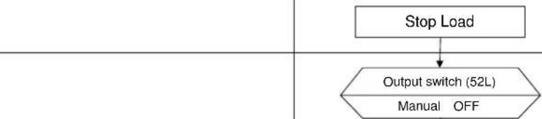 | |
| UPS Panel | OUTAGE | |
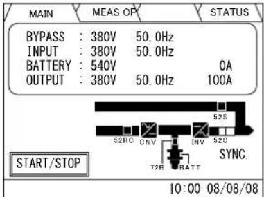
| UPS Panel | 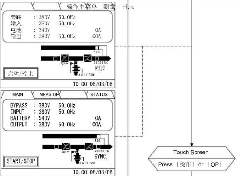 When inverter output voltage and bypass voltage are synchronized, the message "SYNC." or "同步" will be shown on screen. When inverter output voltage and bypass voltage are synchronized, the message "SYNC." or "同步" will be shown on screen. | ↓ |
| Device Touch Screen Flowchart of Shut-down Operation Load status | |||
| UPS Panel | H志 | Touch ScreenPress「关机操作指导」or「SHUTDOWN GUIDANCE」. | (OUTAGE) |
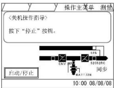 | |||
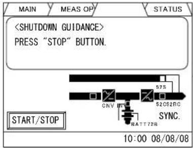 | |||
| 口志 | Touch ScreenPress「启动/停止」or「START/STOP」. | ||
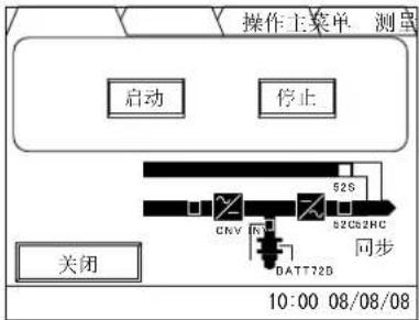 | |||
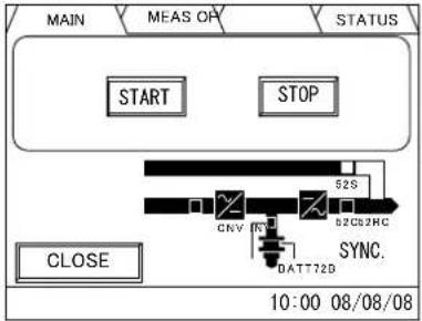 | |||
| Device Display on Touch Screen Flowchart of Shut-down Operation Load Status | |||
| UPS Panel | 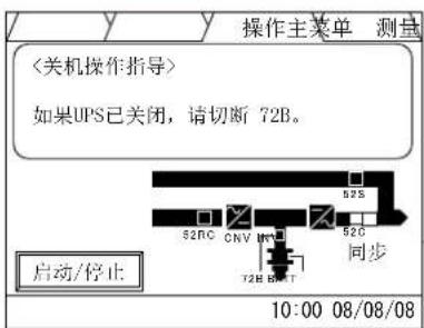 | H志 | (OUTAGE) |
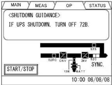 | Bypass Contactor (52S)Automatic ONOutput Contactor (52C)Automatic OFFComplete Shutdown?NO(Load on Bypass)YES(UPS Shutdown)Touch ScreenPress「MAIN」or「主菜单」Load on BypassOperation completedConversion modules (Include inverter and converter) keep supplying power to charge batteries. | ||
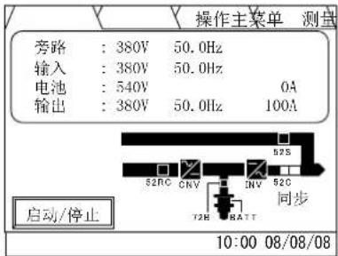 | |||
 | |||
| Device Touch Screen | Flowchart of Shut-down Operation Load Status | ||
| Input Panel | (UPS Shutdown) | (OUTAGE) | |
| Input Panel | 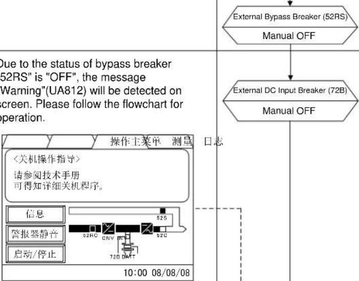 | ||
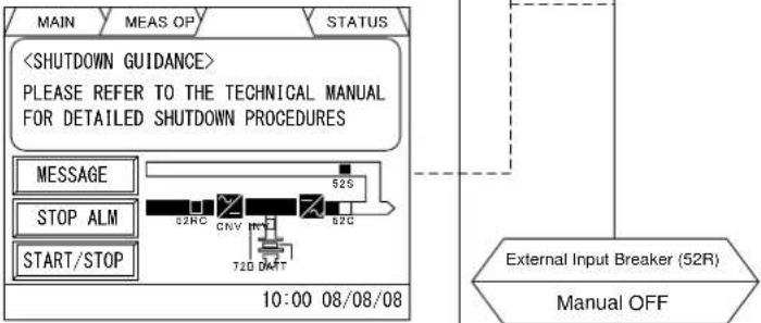 | |||
| Fellow the procedure of operation flowchart, the touch screen will shutdown after turning the external breaker "52R" off. | External DC Input Breaker (72B)Automatic tripInput Contactor (52RC)Automatic OFFUPS Shutdown,Operation completed | ||
- Transfer Procedures (Single-Module System, INVERTER to BYPASS)
| UPS Panel | Touch Screen | Flowchart of Transfer Operation (INVERTER to BYPASS) | Load statusDev | ||
| 操作主菜单 测量 旁路 : 380V 50.0Hz 输入 : 380V 50.0Hz 电池 : 540V 0A 输出 : 380V 50.0Hz 100A 启动/停止 10:00 08/08/08 | 日志 Load on INVERTER SYNC OK? YES NO Transfer disable Touch Screen Press「启动/停止」or「START/STOP」 | Load on Inverter | |||
| MAIN MEAS OP STATUS BYPASS : 380V 50.0Hz INPUT : 380V 50.0Hz BATTERY : 540V 0A OUTPUT : 380V 50.0Hz 100A START/STOP 10:00 08/08/08 | H.总 Touch Screen Press「停止」or「STOP」 | Load on Bypass | |||
| 操作主菜单 测量 启动 停止 关闭 10:00 08/08/08 | H.总 Bypass Switch (52S) Automatic ON Output Contactor (52C) Automatic OFF | Load on Bypass | |||
| MAIN MEAS OP STATUS START STOP CLOSE 10:00 08/08/08 | H.总 Load on BYPASS | ||||
| 操作主菜单 测量 旁路 : 380V 50.0Hz 输入 : 380V 50.0Hz 电池 : 540V 0A 输出 : 380V 50.0Hz 100A 启动/停止 10:00 08/08/08 | H.总 Load on Bypass | ||||
| MAIN MEAS OP STATUS BYPASS : 380V 50.0Hz INPUT : 380V 50.0Hz BATTERY : 540V 0A OUTPUT : 380V 50.0Hz 100A START/STOP 10:00 08/08/08 | H.总 Load on Bypass | ||||
- Transfer Procedures (Single-Module System, Bypass to Inverter)
| UPS Panel | Touch Screen | Flowchart of Transfer Operation (BYPASS to INVERTER) | Load statusDev | ||
| 操作主菜单 测量 旁路 : 380V 50.0Hz 输入 : 380V 50.0Hz 电池 : 540V 0A 输出 : 380V 50.0Hz 100A 启动/停止 10:00 08/08/08 | H点 Load on BYPASS SYNC OK? YES NO Transfer disable Touch Screen Press「启动/停止」or「START/STOP」 | Load on Bypass | |||
| MAIN MEAS OP STATUS BYPASS : 380V 50.0Hz INPUT : 380V 50.0Hz BATTERY : 540V 0A OUTPUT : 380V 50.0Hz 100A START/STOP 10:00 08/08/08 | H点 Touch Screen Press「启动」or「START」 | Load on Inverter | |||
| 操作主菜单 测量 启动 停止 关闭 10:00 08/08/08 | 口志 Output Contactor (52C) Automatic ON | Load on Inverter | |||
| MAIN MEAS OP STATUS START STOP CLOSE 10:00 08/08/08 | |||||
| 操作主菜单 测量 旁路 : 380V 50.0Hz 输入 : 380V 50.0Hz 电池 : 540V 0A 输出 : 380V 50.0Hz 100A 启动/停止 10:00 08/08/08 | |||||
| MAIN MEAS OP STATUS BYPASS : 380V 50.0Hz INPUT : 380V 50.0Hz BATTERY : 540V 0A OUTPUT : 380V 50.0Hz 100A START/STOP 10:00 08/08/08 | |||||
- Transfer Procedures (Single-Module System, Inverter to Maintenance Bypass)
| Device | Touch Screen | Flowchart of Transfer Operation (INVERTER to MAINTENANCE BYPASS) | Load status | ||
| UPS Panel | |||||
| Load on INVERTER | Load on Inverter | ||||
| According to bypass transfer operation, transfer to bypass | Load on Bypass | ||||
| Load on BYPASS | Load on Internal Maintenance Bypass | ||||
| Internal Maintenance Bypass Switch (52M) Manual ON | |||||
| External DC Input Breaker (72B) Manual OFF | |||||
| Input Panel | Manual OFF | ||||
| UPS Panel | Input Contactor (52RC) Automatic OFF | ||||
| Internal Output Switch (52L) Manual OFF | |||||
| Internal Bypass input Switch (52PS) Manual OFF | |||||
| External DC Input Breaker (72B) Automatic trip | |||||
| Load on INTERNAL MAINTENANCE BYPASS | |||||
- Transfer Procedures (Single-Module System, Maintenance Bypass to Inverter)
| Touch Screen | Flowchart of Transfer Operation (MAINTENANCE BYPASS to INVERTER) | Load statusDev | |
| UPS Panel | Load on INTERNAL MAINTENANCE BYPASSInternal Bypass input Switch (52PS)Manual ONExternal Input Breaker (52R)Manual ONInput contactor (52RC)Automatic ONConverterAutomatic Start-upInverterAutomatic Start-upExternal DC Input Breaker (72B)Manual ONInternal Output Switch (52L)Manual ONInternal Maintenance Bypass Switch (52M)Manual OFFAccording to inverter transfer operation, transfer to inverterLoad on INVERTER | Load on Internal Maintenance Bypass | |
| Input Panel | |||
| UPS Panel | 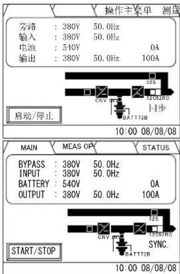 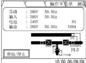 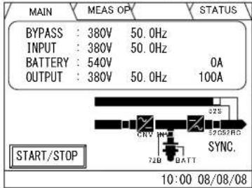 |
3.5.2 Start-up / Shut-down (MMS with Individual Bypass Parallel Redundancy)
Parallel system of two UPS modules (MMS) with general configuration of Individual Parallel Redundancy System is shown in FIGURE 3.9.
In MMS system, Internal switches must be kept the status as follows.
FIGURE 3.9 Circuit configuration of Individual Bypass Parallel Redundancy System
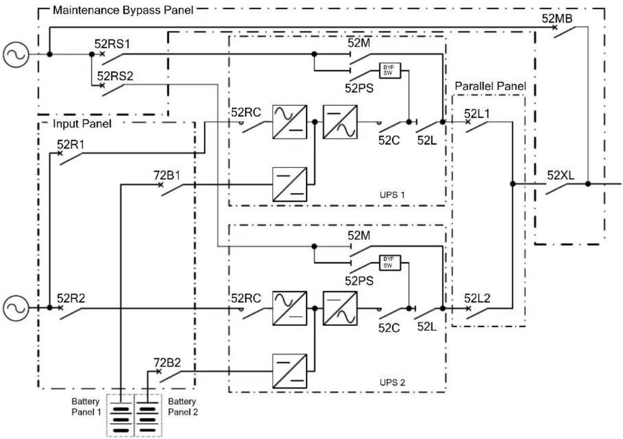
flowchart
graph TD
    A["~"] --> B["52RS1"]
    A --> C["52RS2"]
    B --> D["Input Panel"]
    C --> D
    D --> E["72B1"]
    E --> F["52RC"]
    F --> G["52RC"]
    G --> H["52PS"]
    H --> I["52M"]
    I --> J["52PS"]
    J --> K["52C"]
    K --> L["52L"]
    L --> M["Parallel Panel"]
    M --> N["52L1"]
    N --> O["52XL"]
    O --> P["52MB"]
    P --> Q["52MB"]
    Q --> R["52ML"]
    R --> S["UPS 1"]
    S --> T["52MC"]
    T --> U["52MC"]
    U --> V["52PS"]
    V --> W["52C"]
    W --> X["52L"]
    X --> Y["UPS 2"]
    Y --> Z["72B2"]
    Z --> AA["52R2"]
    AA --> AB["~"]
    AB --> AC["Battery Panel 1"]
    AB --> AD["Battery Panel 2"]
The operation of system start in the status of "Load on maintenance bypass". (Confirm all of the switches is opened or in tripping position besides 52MB.).
- Start-up Procedure (MMS with Individual Bypass Parallel Redundancy)
| Device | Touch Screen Flowchart of Start-up Operation Load Status | |||
| Load | Confirm the loads had turned OFF | OUTAGE | ||
| Maintenance Bypass Panel | When external bypass breaker turned to "NO", the status of power supply will be shown on the MAIN screen.Due to the status of input breaker "52R" is "OFF", the message "Warning"(UA801) will be detected. Please follow the next indication for operation.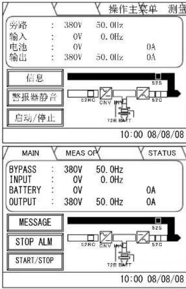 | Confirm output breaker (52L) and maintenance bypass breaker (52MB) is opened.External Bypass Breaker (52RS)Manual ON | ||
| Input Panel | 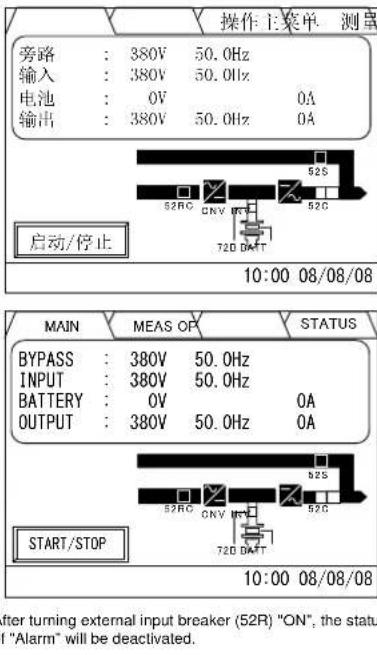 A O S A O S | External Input Breaker (52R)Manual ONInput Contactor (52RC)Automatic ONConverterAutomatic Start-upInverterAutomatic Start-up | ||
| Device | Touch Screen | Flowchart of Start-up Operation(All UPS) | Load Status | |
| UPS Panel(Operate sequentially from No.1 UPS) | 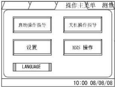 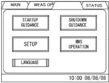 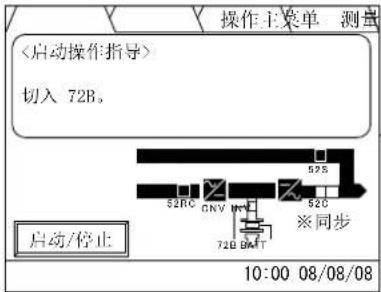 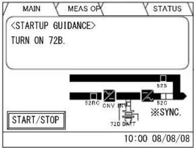 | [口志] | (OUTAGE) | |
| [口志] | ||||
| [口志] | ||||
| [口志] | ||||
| [口志] | ||||
| Device Touch Screen | Flowchart of Start-up Operation(All UPS) | Load Status | ||
| Input Panel | 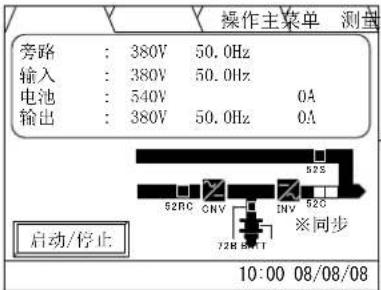 | H志 | 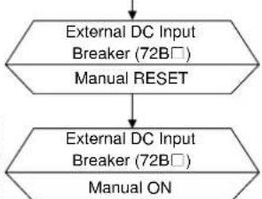 | (OUTAGE) |
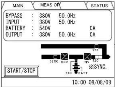 |  | |||
| Maintenance Bypass Panel | 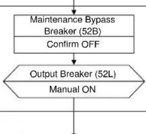 | Load on Bypass | ||
| UPS Panel(Any one of the parallel UPSs) | 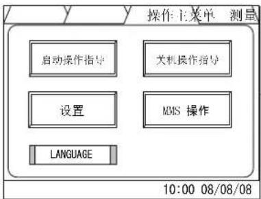 | 口志 | 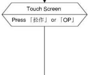 | |
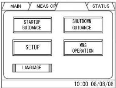 | ||||
☐: Operate sequentially from No.1 UPS
| Device | Touch Screen | Flowchart of Start-up Operation(All UPS) | Load Status |
| UPS Panel(Any one of the parallel UPSs) | 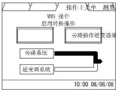 | 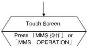 | (Load on Bypass) |
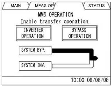 | 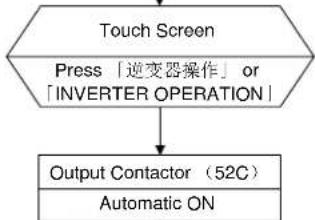 | Load on Inverter | |
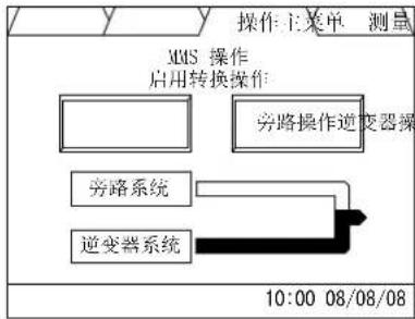 | 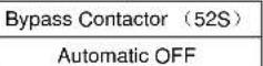 | ||
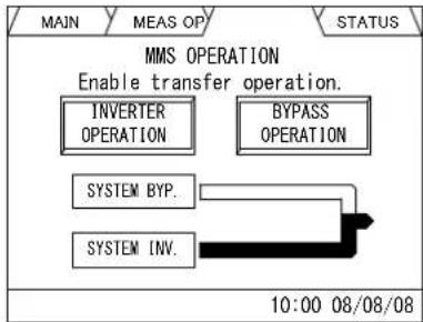 | |||
| UPS Panel(Operate sequentially from No.1 UPS) | 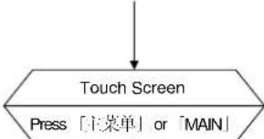 | (Load on Inverter) | |
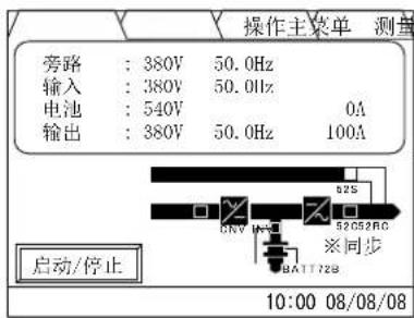 | 日志 | ||
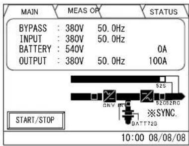 | |||
| UPS Start-UP completed |
UPS Start-UP completed
●Shut-down Procedure (MMS with Individual Bypass Parallel Redundancy)
| Device | Touch Screen | Flowchart of Shut-Down Operation(All UPS) | Load Status |
| Load | Stop Load | Load Stop | |
| Maintenance Bypass Panel | Output Breaker (52L)Manual OFF | OUTAGE | |
| UPS Panel(Any one of the parallel UPSs) | 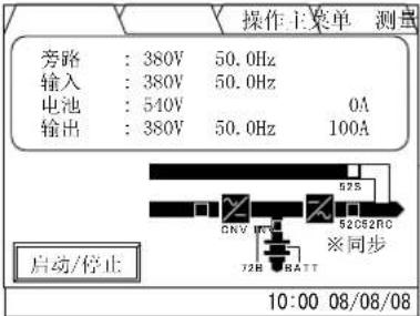 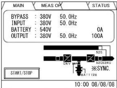 When inverter output voltage and bypass voltage are synchronized, the message "SYNC." or "同步" will be shown on screen.The mark "※" indicates the master UPS in the parallel system. (the mark is not shown in the Single-Module system) When inverter output voltage and bypass voltage are synchronized, the message "SYNC." or "同步" will be shown on screen.The mark "※" indicates the master UPS in the parallel system. (the mark is not shown in the Single-Module system)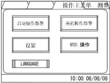 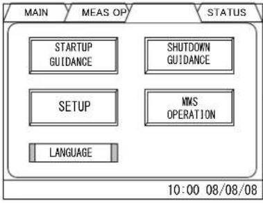 | 口志 | |
| Touch ScreenPress「操作」or「OP」 | |||
| 口志 | |||
When inverter output voltage and bypass voltage are synchronized, the message "SYNC." or "同步" will be shown to screen. The mark "※" indicates the master UPS in the parallel system. (the mark is not shown in the Single-Module system)
| Device Touch Screen | Flowchart of Shut-Down Operation (All UPS) | Load Status |
| UPS Panel (Any one of the parallel UPSs.) | 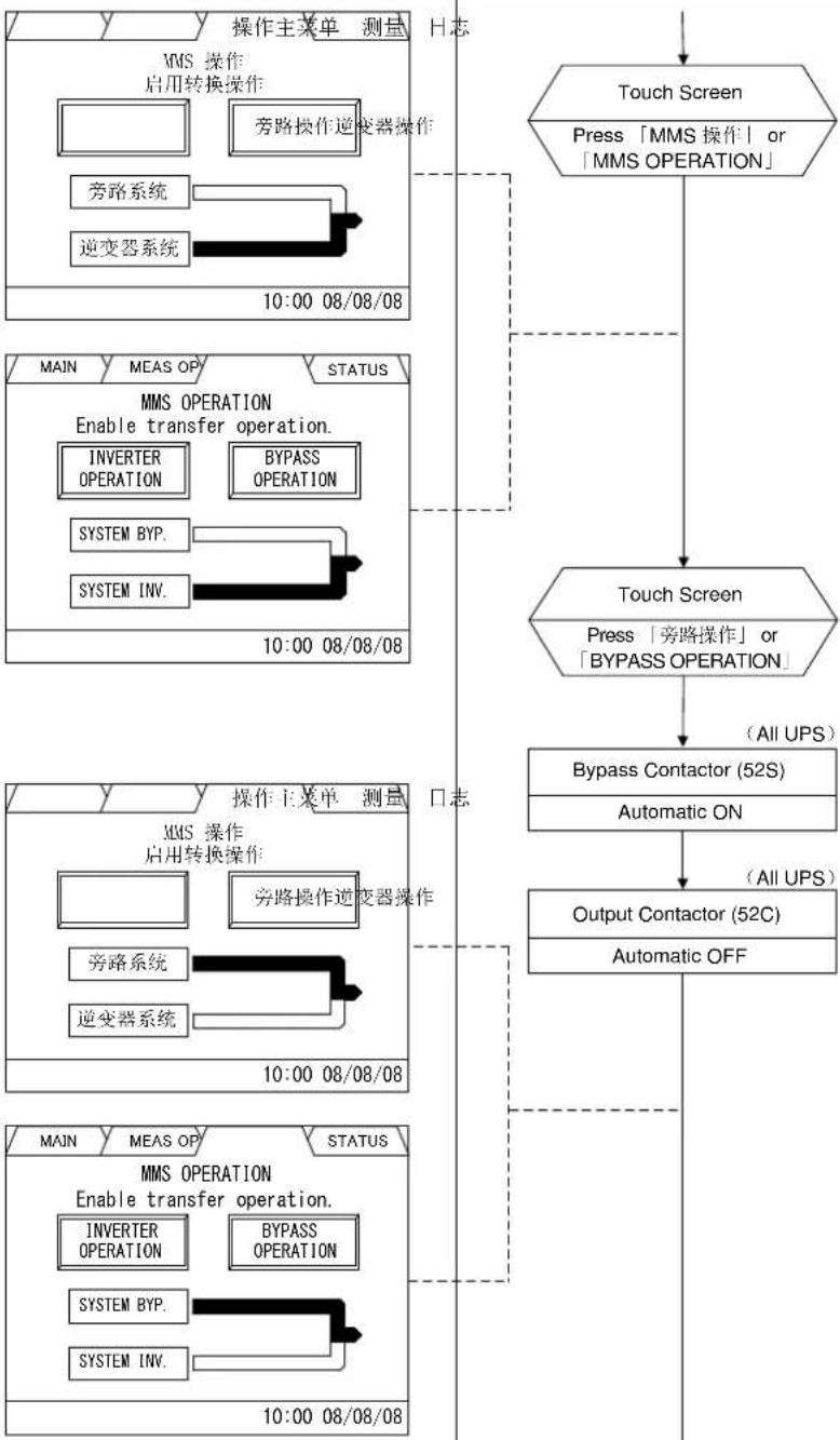 | (OUTAGE) |
UPS Panel(Any one of the parallel UPSs)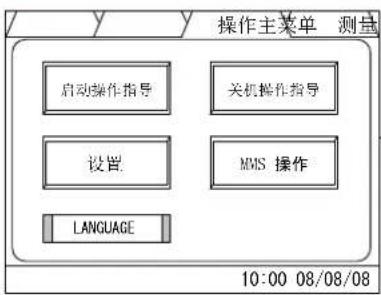 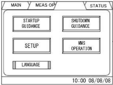 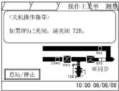 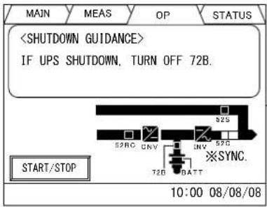 | H志Touch ScreenPress「操作」or「OP」Touch ScreenPress「关机操作指导」or「SHUTDOWN GUIDANCE」口志From next page | (OUTAGE) |
| UPS Panel |
☐: Operate sequentially from No.1 UPS
| Device Touch Screen | Flowchart of Shut-Down Operation(All UPS) | Load Status | ||
| Input Panel | Due to the status of bypass breaker "52RS" is "OFF", the message "Warning"(UA812) will be detected. Please follow the flowchart for operation. | |||
| KC4A | 口志 | (Load on Bypass)(UPS Shutdown)To previous page | (OUTAGE) | |
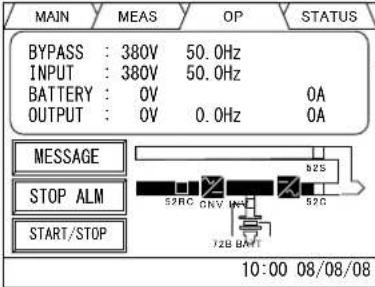 | 日志 | External DC Input Breaker (72B□)Manual OFF | ||
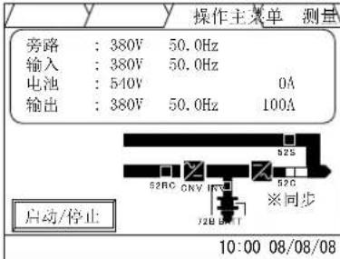 | External Input Breaker (52R□)Manual OFF | |||
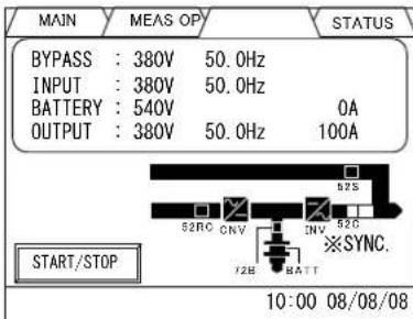 | External DC Input Breaker (72B)Automatic Trip | |||
| Input Contactor(52RC)Automatic OFF | ||||
| All UPSs ShutdownOperation completeNO | ||||
| All UPSs Normal Stop Operation completeYES | ||||
| Normal Stop Operation completeShutdown Operation complete | ||||
☐: Operate sequentially from No.1 UPS
4.0 RESPONSE TO UPS FAILURE
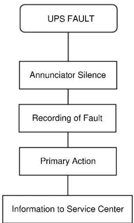
flowchart
graph TD
    A["UPS FAULT"] --> B["Annunciator Silence"]
    B --> C["Recording of Fault"]
    C --> D["Primary Action"]
    D --> E["Information to Service Center"]
natural_image
Two speaker cone illustrations showing sound waves, no text or symbols presentDepress "SILENCE ALARM" icon on Main Menu.
Refer to the list of fault codes in section 6.0 for error description.
Take necessary action according to display guidance.
When faults happen, contact the Authorized MITSUBISHI Service Representatives.

Note
The error code indicated on the LCD display panel when an UPS alarms is very important.
In order to reduce repair time, please include this information, along with the operation and load status for all correspondence to MITSUBISHI field service group.
5.0 PARTS REPLACEMENT
Contact MITSUBISHI or its authorized service representatives on all issues regarding the replacement of parts.
A) Battery
Battery lifetime may vary according to the frequency of use and the average ambient operating temperature. The end of battery life is defined as the state of charge resulting in an ampere-hour capacity less than, or equal to, 80% of nominal capacity. Replace battery if its capacity is within this percentage.
B) UPS Component Parts
UPS components have a defined life expectancy (Fans, Capacitors, Filters, etc.)
Contact MITSUBISHI or its authorized service representatives for a complete parts replacement schedule. Recommended replacement time interval varies with operating environment.
Contact MITSUBISHI or its authorized service representatives for application specific recommendations.

Any parts replacements (including modification) without authorized by MITSUBISHI could result in personal injuries, death or destruction of the UPS.

Power shutdown and wait 5min for internal capacitors discharge and stopped rotating of fans should be confirmed before any replacement work.
6.0 FAULT CODES
This section covers fault codes, their description and required action.
At time of error :
A) Verify and record the occurrence of the alarm. Note details of alarm message displayed on the LCD display panel.
B) If a circuit breaker (MCCB) has tripped, depress the toggle to reset the breaker before closing it again.
(Conditions of MCCB)
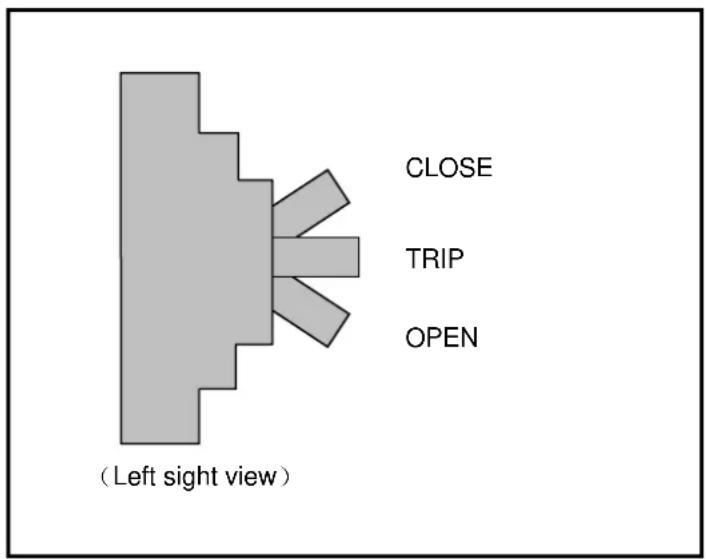
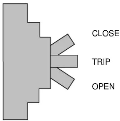
Failure Code List
Table 6.1 Fault Code
| Code indication (Note 3) | Status message | Meaning | Guidance | Buzzer | External relay contact (Note 1) | Failure Lamp (Note 2) |
| UA801 | AC INPUT VOLTAGE OUT OF RANGE | Input line voltage is out of the specified range. | CHECK INPUT POWER SOURCE | Intermittent sound | Alarm AC input abnormal | — |
| UA802 | AC INPUT FREQUENCY OUT OF RANGE | Input line frequency is out of the specified range. | CHECK INPUT POWER SOURCE | Intermittent sound | Alarm AC input abnormal | — |
| UA803 | AC INPUT PHASE ROTATION ERROR | Input line power conductors are not wired in a proper phase sequence. | CHECK INPUT POWER SOURCE | Intermittent sound | Alarm AC input abnormal | — |
| UA804 | CONVERTER OPE. PROHIBITION | The converter interlock is active. — | Intermittent sound | Alarm — | ||
| UA805 | INVERTER OVERLOAD | The output load current has exceeded 105% of the rated current. | WARNING : DECREASE LOAD | Intermittent sound | Alarm Overload | — |
| UA806 | INVERTER OVERLOAD | The output load current has exceeded 110% of the rated current. | WARNING : DECREASE LOAD | Intermittent sound | Alarm Overload | — |
| UA807 | INVERTER OVERLOAD | The output load current has exceeded 125% of the rated current. | WARNING : DECREASE LOAD | Intermittent sound | Alarm Overload | — |
| UA808 | INVERTER OVERLOAD | The output load current has exceeded 150% of the rated current. | WARNING : DECREASE LOAD | Intermittent sound | Alarm Overload | — |
| UA810 | INVERTER OVERLOAD | Short time over-current has been detected during the inverter operation. | WARNING : DECREASE LOAD | Intermittent sound | Alarm Overload | — |
| UA812 | BYPASS VOLTAGE OUT OF RANGE | Bypass line voltage is out of the specified range. | CHECK BYPASS INPUT | Intermittent sound | Alarm Bypass input abnormal | — |
| UA813 | BYPASS PHASE ROTATION ERROR | Bypass line power conductors are not wired in a proper phase sequence. | CHECK BYPASS INPUT | Intermittent sound | Alarm Bypass input abnormal | — |
| UA814 | BYPASS FREQUENCY OUT OF RANGE | Bypass line frequency is out of the specified range. | CHECK BYPASS INPUT | Intermittent sound | Alarm Bypass input abnormal | — |
| UA815 | TRANSFER PROHIBITION | Transfer to the bypass is not available due to bypass abnormality. | — | Intermittent sound | Alarm — | |
| UA817 | EMERGENCY STOP ACTIVATED | The emergency stop was activated by the EPO switch or an external contact. | — — Alarm | — | ||
| UA821 | TRANSFER PROHIBITION | The UPS could not transfer to the bypass because the inverter output was not synchronized to the bypass. | — — Alarm | — | ||
| UA822 | TRANSFER PROHIBITION | The UPS could not transfer to the bypass because of backup generator operation. | — — Alarm — | |||
| UA824 72B | OPEN | The battery circuit breaker (72B) is open. | TURN ON 72B | Intermittent sound | Alarm — | |
| UA827 | 52C OPE. PROHIBITION | The interlock for the inverter output contactor (52C) is active. | — | Intermittent sound | Alarm — | |
| UA828 | FAN ALARM | Cooling fan abnormal. | — | Intermittent sound | Alarm — | |
| UA831 | EMERGENCY BYPASS SWITCH ON | Emergency bypass switch has been turned on. | — | Intermittent sound | Alarm — | |
| UA833 52L | OPEN | The load circuit breaker(52L) is turned off. | — | Intermittent sound | Alarm — | |
| UA834 | BATTERY DEPLETED/AC OUT STOPPED | The battery voltage has reached the depleted level. | — — | Major End-of-Discharge | Lit on | |
| UA835 | TRANSFER PROHIBITION | The UPS could not transfer to the bypass because the bypass source has an abnormality. | — — Alarm — | |||
| UA838 | 52M OPERATION | Status of 52M ON and 52L open. | CALL SERVICE ENGINEER | — | Alarm | — |
| UA839 | 52M OPERATION | Status of 52M ON and 52L ON. | CALL SERVICE ENGINEER | — | Alarm | — |
| UA860 | REMOTE BUTTON ABNORMAL | Remote start or stop signal is being received continuously for a considerable time. | — | Intermittent sound | Alarm — | |
| UA861 | LOCAL BUTTON ABNORMAL | Local start or stop signal is being received continuously for a considerable time. | — | Intermittent sound | Alarm — | |
| UA870 | BALANCER OVERLOAD | The UPS detected an neutral point voltage unbalance. | — | Intermittent sound | Alarm Overload | — |
| UA890 | EXTERNAL ALARM | External Alarm relay turned on. | — | Intermittent sound | Alarm — | |
| UF001 | INPUT CIRCUIT ABNORMAL | Detection of a large variation of the reference error signal. | CALL SERVICE ENGINEER | Continuous sound | Major | Lit on |
| UF002 | CONVERTER OVERCURRENT | Detection of converter overcurrent. | CALL SERVICE ENGINEER | Continuous sound | Major | Lit on |
| UF003 | CONVERTER ABNORMAL | Pre-charging circuit is not working properly. | CALL SERVICE ENGINEER | Continuous sound | Major | Lit on |
| UF011 | 52RC ABNORMAL | Major discrepancy between reference signal and actual state of contactor 52RC. | CALL SERVICE ENGINEER | Continuous sound | Major | Lit on |
| UF052 | 52RC ABNORMAL | Minor discrepancy between reference signal and actual state of contactor 52RC. | CALL SERVICE ENGINEER | Intermittent sound | Minor | Flicker |
| UF056 | CONVERTER OVERCURRENT | Detection of converter overcurrent. | CALL SERVICE ENGINEER | Intermittent sound | Minor | Flicker |
| UF059 | INPUT CIRCUIT ABNORMAL | Detection of a large variation of the reference error signal. | CALL SERVICE ENGINEER | Intermittent sound | Minor | Flicker |
| UF102 | DC OVERVOLTAGE | DC voltage surpasses the overvoltage level. | CALL SERVICE ENGINEER | Continuous sound | Major | Lit on |
| UF103 | DC UNDERVOLTAGE | DC voltage dropped below the undervoltage level. | CALL SERVICE ENGINEER | Continuous sound | Major Lit on | |
| UF108 | CHOPPER OVERCURRENT | Detection of DC overcurrent. | CALL SERVICE ENGINEER | Continuous sound | Major Lit on | |
| UF109 DC | UNBALANCED | Major unbalance of the neutral point voltage. | CALL SERVICE ENGINEER | Continuous sound | Major Lit on | |
| UF111 | UPS CONTROL CIRCUIT ERROR | Battery current unbalance. | CALL SERVICE ENGINEER | Continuous sound | Major Lit on | |
| UF112 | DC CIRCUIT ABNORMAL | Sudden change of the DC voltage level. | CALL SERVICE ENGINEER | Continuous sound | Major Lit on | |
| UF128 | CONTROL POWER SUPPLY ABNORMAL | Power supply voltage to IGBT driver PCB is below the specified level. | CALL SERVICE ENGINEER | Continuous sound | Major Lit on | |
| UF151 | DC VOLTAGE ABNORMAL | 24 hours after input power restoration, batteries does not reach float voltage level. | CALL SERVICE ENGINEER | Intermittent sound | Minor Flicker | |
| UF152 | DC VOLTAGE ABNORMAL | Unable to equalize the voltage of various batteries after 24 hours. | CALL SERVICE ENGINEER | Intermittent sound | Minor Flicker | |
| UF154 72B | ABNORMAL | During UVT, status signal from 72B is ON. | CALL SERVICE ENGINEER | Intermittent sound | Minor Flicker | |
| UF156 | CHG.STOPPED(BATTERY OVERTEMP.) | UF157 failure persisted for over 2 hours. | CHECK BATTERY | Intermittent sound | Minor Battery abnormal | Flicker |
| UF157 | BATTERY OVERTEMPERATURE | Detection of overtemperature at the batteries. | CHECK BATTERY | Intermittent sound | Minor Battery abnormal | Flicker |
| UF158 | BATTERY LIQUID LOW | Low level of battery electrolyte solution. | CHECK BATTERY | Intermittent sound | Minor Battery abnormal | Flicker |
| UF160 | UPS CONTROL CIRCUIT ERROR | Abnormal behavior of DC current sensor. | CALL SERVICE ENGINEER | Intermittent sound | Minor Flicker | |
| UF161 | CHG.STOPPED(DCVOLT.ABNORMAL) | UF151 failure is running for over 24 hours. | CALL SERVICE ENGINEER | Intermittent sound | Minor Flicker | |
| UF162 | BATTERY ABNORMAL | Failure detection based on battery self-check. | CALL SERVICE ENGINEER | Intermittent sound | Minor Flicker | |
| UF163 | BATTERY VOLTAGE ABNORMAL | Battery voltage is abnormality. | CALL SERVICE ENGINEER | Intermittent sound | Minor Flicker | |
| UF170 | VDB SENSOR ABNORMAL | Detection of a large variation of the difference between control-only and protection-only battery voltage. | CALL SERVICE ENGINEER | Intermittent sound | Minor Flicker | |
| UF171 | UPS CONTROL CIRCUIT ERROR | Poor shared current in parallel chopper circuit; or improper charging current. | CALL SERVICE ENGINEER | Intermittent sound | Minor Flicker | |
| UF172 | CHG.STOPPED (DEVICE STATUS) | Energy storage device error. | CALL SERVICE ENGINEER | Intermittent sound | Minor Flicker | |
| UF201 | INVERTER OVERVOLTAGE | Detection of output overvoltage. | CALL SERVICE ENGINEER | Continuous sound | Major Lit on | |
| UF202 | INVERTER UNDERVOLTAGE | Output voltage dropped. | CALL SERVICE ENGINEER | Continuous sound | Major Lit on | |
| UF203 | INVERTER OVERCURRENT | Detection of inverter overcurrent. | CALL SERVICE ENGINEER | Continuous sound | Major Lit on | |
| UF204 | OUTPUT CIRCUIT ABNORMAL | Detection of a large variation of the reference error signal (current reference and actual current). | CALL SERVICE ENGINEER | Continuous sound | Major Lit on | |
| UF206 | UPS CONTROL CIRCUIT ERROR | Discrepancy between output voltage and external voltage (bypass, common ac bus) | CALL SERVICE ENGINEER | Continuous sound | Major Lit on | |
| UF208 | UPS CONTROL CIRCUIT ERROR | Cross current is abnormality. | CALL SERVICE ENGINEER | Continuous sound | Major Lit on | |
| UF209 | 52C ABNORMAL | Error to close the contactor 52C. | CALL SERVICE ENGINEER | Continuous sound | Major Lit on | |
| UF210 | 52C ABNORMAL | Error to open the contactor 52C. | CALL SERVICE ENGINEER | Continuous sound | Major Lit on | |
| UF211 52C | ABNORMAL | No answer from contactor 52C during inverter operation. | CALL SERVICE ENGINEER | Continuous sound | Major Lit on | |
| UF213 | OVERTEMPERATU RE | Heatsinks temperature exceeds thermal settings. | CALL SERVICE ENGINEER | Continuous sound | Major Lit on | |
| UF214 | COOLING FAN ABNORMAL | Thermal relay activated protection. | CALL SERVICE ENGINEER | Continuous sound | Major Lit on | |
| UF217 | INVERTER OVERVOLTAGE | Detection of inverter output phase overvoltage. | CALL SERVICE ENGINEER | Continuous sound | Major Lit on | |
| UF253 | UPS CONTROL CIRCUIT ERROR | Discrepancy between output voltage and inverter voltage, or between output voltage and bypass voltage. | CALL SERVICE ENGINEER | Intermittent sound | Minor Flicker | |
| UF256 | OUTPUT VOLTAGE ABNORMAL | Output voltage is out of the specified range. | CALL SERVICE ENGINEER | Intermittent sound | Minor Flicker | |
| UF257 52C | ABNORMAL | Contactor 52C failed to open during load transfer from inverter to bypass. | CALL SERVICE ENGINEER | Intermittent sound | Minor Flicker | |
| UF258 LOAD | ABNORMAL | Load transfer due to overload for over 4 times within 5 minutes. | CALL SERVICE ENGINEER | Intermittent sound | Minor Flicker | |
| UF259 | ANOTHER UPS ABNORMAL | No detection of another UPS voltage signal. | CALL SERVICE ENGINEER | Intermittent sound | Minor Flicker | |
| UF301 | UPS CONTROL CIRCUIT ERROR | AD reference has an abnormal value. | CALL SERVICE ENGINEER | Continuous sound | Major Lit on | |
| UF302 | UPS CONTROL CIRCUIT ERROR | Detection of an external interruption during the software execution. | CALL SERVICE ENGINEER | Continuous sound | Major Lit on | |
| UF303 | UPS CONTROL CIRCUIT ERROR | Timer does not reset in the specified period (WDT settings) | CALL SERVICE ENGINEER | Continuous sound | Major Lit on | |
| UF305 | UPS CONTROL CIRCUIT ERROR | Detection of an abnormal clock speed in the DSP or FPGA. | CALL SERVICE ENGINEER | Continuous sound | Major Lit on | |
| UF306 | UPS CONTROL CIRCUIT ERROR | Control power supply voltage are below the specified level. | CALL SERVICE ENGINEER | Continuous sound | Major Lit on | |
| UF309 | INVERTER VOLTAGE ABNORMAL | Inverter voltage is out of the specified range. | CALL SERVICE ENGINEER | Continuous sound | Major Lit on | |
| UF310 | CONTROL POWER SUPPLY ABNORMAL | Backup control power supplies exhibit abnormal condition. | CALL SERVICE ENGINEER | Continuous sound | Major Lit on | |
| UF320 | UPS CONTROL CIRCUIT ERROR | Cable disconnection in the parallel interface board during load supply. | CALL SERVICE ENGINEER | Continuous sound | Major Lit on | |
| UF323 | UPS CONTROL CIRCUIT ERROR | Major communication error during parallel operation. | CALL SERVICE ENGINEER | Continuous sound | Major Lit on | |
| UF331 | UPS CONTROL CIRCUIT ERROR | Gate driver abnormal for phase U (Note 4) | CALL SERVICE ENGINEER | Continuous sound | Major Lit on | |
| UF332 | UPS CONTROL CIRCUIT ERROR | Gate driver abnormal for phase V (Note 4) | CALL SERVICE ENGINEER | Continuous sound | Major Lit on | |
| UF333 | UPS CONTROL CIRCUIT ERROR | Gate driver abnormal for phase W (Note 4) | CALL SERVICE ENGINEER | Continuous sound | Major Lit on | |
| UF334 | UPS CONTROL CIRCUIT ERROR | Gate driver abnormal for chopper (Note 4) | CALL SERVICE ENGINEER | Continuous sound | Major Lit on | |
| UF352 | CONTROL POWER SUPPLY ABNORMAL | Backup control power supplies exhibit abnormal condition. | CALL SERVICE ENGINEER | Intermittent sound | Minor Flicker | |
| UF363 | UPS CONTROL CIRCUIT ERROR | Synchronization status signal is being received for a considerable time. | CALL SERVICE ENGINEER | Intermittent sound | Minor Flicker | |
| UF371 | UPS CONTROL CIRCUIT ERROR | Minor communication error during parallel operation. | CALL SERVICE ENGINEER | Intermittent sound | Minor Flicker | |
| UF372 | UPS CONTROL CIRCUIT ERROR | Unable to synchronize the inverter output and the bypass voltage. | CALL SERVICE ENGINEER | Intermittent sound | Minor Flicker | |
| UF374 | UPS CONTROL CIRCUIT ERROR | Cable disconnection in the parallel interface board. | CALL SERVICE ENGINEER | Intermittent sound | Minor Flicker | |
| UF375 | UPS CONTROL CIRCUIT ERROR | Unable to achieve synchronization for parallel operation. | CALL SERVICE ENGINEER | Intermittent sound | Minor Flicker | |
| UF376 | UPS CONTROL CIRCUIT ERROR | No control response from another UPS although its detection is possible. | CALL SERVICE ENGINEER | Intermittents sound | Minor Flicker | |
| UF377 | UPS CONTROL CIRCUIT ERROR | Overload detection signal is being received continuously for a considerable time. | CALL SERVICE ENGINEER | Intermittent sound | Minor Flicker | |
| UF378 | UPS CONTROL CIRCUIT ERROR | No answer for sending synchronizing signal. | CALL SERVICE ENGINEER | Intermittent sound | Minor Flicker | |
| UF379 | UPS CONTROL CIRCUIT ERROR | Abnormal clock speed of the parallel control board processor. | CALL SERVICE ENGINEER | Intermittent sound | Minor Flicker | |
| UF381 | STS CONTROL CIRCUIT ERROR | STS current value abnormal. | CALL SERVICE ENGINEER | Intermittent sound | Minor Flicker | |
| UF401 | 52S ABNORMAL | Error to close the contactor 52S. | CALL SERVICE ENGINEER | Continuous sound | Major Lit on | |
| UF402 | 52S ABNORMAL | Error to open the contactor 52S. | CALL SERVICE ENGINEER | Continuous sound | Major Lit on | |
| UF420 | 52L OPERATION ERROR | Load circuit breaker 52L opened during inverter operation. | CHECK 52L | Continuous sound | Major Lit on | |
| UF451 52S | ABNORMAL | Contactor 52S failed during load transfer from inverter to bypass. | CALL SERVICE ENGINEER | Intermittent sound | Minor Flicker | |
| UF453 | 52M ABNORMAL | 52M abnormal. | CALL SERVICE ENGINEER | Continuous sound | Minor Flicker | |
| UF461 | STS COOLING FAN ABNORMAL | STS cooling fan abnormal detected. | CALL SERVICE ENGINEER | Continuous sound | Minor Flicker | |
| UF462 | STS CONTROL CIRCUIT ERROR | Both UF461, UF463 occurred. | CALL SERVICE ENGINEER | Continuous sound | Minor Flicker | |
| UF463 | STS OVERTEMPER ATURE | STS unit over temperature. | CALL SERVICE ENGINEER | Continuous sound | Minor Flicker | |
| UF465 | STS OVERTEMPER ATURE | STS unit over temperature and load on bypass over 30% | CALL SERVICE ENGINEER | Intermittent sound | Major Lit on | |
(Note 1) 1) "Major" is defined as major failure. Inverter transferred to the static bypass line;
2) "Minor" is defined as a minor failure. UPS continues to operate normally, but cause of alarm must be identified;
(Note 2) Indicates one of two possible LED illumination patterns - continuously on (lit on) or intermittent (flicker).
(Note 3) Code indication means:
| UA+++ | Alarm |
| UF+++ | Failure |
| U%0++ | Rectifier circuit failure |
| U%1++ | DC circuit failure |
| U%2++ | Inverter circuit failure |
| U%3++ | Control circuit failure |
| U%4++ | Bypass system failure |
| U%8++ | Alarm |
| U%+00 - U%+49 | Major failure |
| U%+50 - U%+99 | Minor failure |
*) “+” denotes any numeral from 0 to 9 *) “%” denotes either “A” or “F”
7.0 DAILY INSPECTION
Please perform the daily inspection while the UPS is running. The daily inspection items are shown in Table 7.1.

The customers can only inspect exterior or environment of cabinet. When the customers want to perform the detailed inspection, contact the Authorized MITSUBISHI Service Representatives.
TABLE 7.1 How to perform daily inspection
| No. | Subject | Procedure | Criteria and/or Action needed | ||
| Term | Period | Method/Tool | |||
| 1. | Environmental ambient | Dust or Gas | Daily | Visual check and smelling | Ventilate room atmosphere if dusty or smelling gas. |
| Dewdrops Condensation | Daily | Visual check | Fix the dripping source Dehumidify upon necessity. | ||
| Temperature Humidity | Daily | Thermometer hygrometer | Temperature: 32~104°F Humidity: 30~90% No condensation. To be controlled at 77°F or about by A/C. | ||
| 2. | Cabinet Construction | Vibration or Audible noise | Daily | Touch and hearing | Check if fans have irregular sound. Contact service representative in case of abnormalities. |
| Overheating | When needed | Touching exterior | Contact service representative in case of abnormalities. | ||
| Air filter clog | When needed | Visual check | Clean/wipe if clogged or dusty. | ||
| 3. | Operation | LCD sharpness Brightness Left-bottom LED | Daily | Visual check | No characters faded, illegible or any other abnormalities. Left-bottom LED should be green. Contact service representative when the LED shows red with the backlight lost. |
| Indication terms: Output voltage Output current AC input voltage Output frequency Battery voltage Battery current DC voltage | Daily | Visual check | Check indication terms/values if within the adequate window. Also check indication meters on surface of optional cabinet, if installed. | ||
| 4. | LEDs | 4 status LEDs | Daily | Visual check | Check if LEDs turn on, off or flash according to the operation. |
| 2 fault LEDs | Daily | Visual check | If UPS fault LED turns on, scroll the screen to see fault codes and record the codes. Contact service representative to tell about fault codes and UPS symptom. | ||
*Air filter also need to be checked during the daily inspection by visual check. Air filter required to clean up 3 month period.
- M9950 SERIES
- TABLE OF CONTENTS
- LIST OF TABLES
- LIST OF FIGURES
- HOW TO USE THIS MANUAL
- INTRODUCTION
- IMPORTANT SAFETY INSTRUCTIONS SAVE THESE INSTRUCTIONS
- WARNING 1
- WARNING 2
- SAFETY PRECAUTIONS
- APPLICATION
- WARNING 3
- WARNING 4
- WARNING 5
- GENERAL
- DEFINITIONS
- LCD Touch Panel Monitor Display
- Display PCB DPAU-81 (FIGURE 1.5):
- External Communication Connector
- Main PCB UPHR-K\*/UPJR-E\* (FIGURE 1.8):
- Parallel control PCB TLCR-H (not shown)
- Grounding Bar (E)
- AC input, AC output, DC input terminal
- External I/F PCB IOAU-09 (FIGURE 1.6):
- Power supply PCB PSAU-80
- "RESET" switch (FOR SERVICE PERSONNEL ONLY)
- "TEST" switch (FOR SERVICE PERSONNEL ONLY)
- "MAINTENANCE" switch (FOR SERVICE PERSONNEL ONLY)
- "RESET" switch (FOR SERVICE PERSONNEL ONLY)
- "BOOT" switch (FOR SERVICE PERSONNEL ONLY)
- "52L S/W" switch (FOR SERVICE PERSONNEL ONLY)
- External contact signal terminal block
- SYSTME SINGLE LINE DIAGRAM
- SPECIFICATIONS
- OPERATION CONTROLS AND INDICATORS
- LED DISPLAY
- EPO BUTTON (Emergency Power Off button) (7)
- LIQUID CRYSTAL DISPLAY (8)
- MENU
- A) MAIN MENU (FIGURE 2.2)
- 1) Startup/Shutdown Guidance (FIGURE 2.3)
- B) MEASUREMENT MENU (FIGURE 2.4)
- INPUT POWER FAILURE (FIGURE 2.7)
- FAULT INDICATION (FIGURE 2.8)
- 1) MESSAGE (FIGURE 2.9)
- EXTERNAL SIGNAL TERMINAL BLOCK
- A) Output Contacts (for external alarm annunciation)
- B) Input Contacts (for remote access of UPS)
- Details of input contacts for remote access : TN1
- INSTALLATION AND OPERATION
- TRANSPORTATION AND INSTALLATION
- INSTALLATION PROCEDURE
- A) Note the load tolerance of the floor
- B) Minimum clearance required for ventilation
- C) Space requirement for routine maintenance
- D) External Battery Supply
- PROCEDURE FOR CABLE CONNECTIONS \*
- Two (2) sources feeding the UPS:
- One (1) source feeding the UPS:
- RECOMMENDED CABLE SIZES
- OPERATING PROCEDURES
- Start-up/Shut-down Procedure (Single Module System)
- Start-up / Shut-down (MMS with Individual Bypass Parallel Redundancy)
- RESPONSE TO UPS FAILURE
- Note
- PARTS REPLACEMENT
- A) Battery
- B) UPS Component Parts
- FAULT CODES
- Failure Code List
- DAILY INSPECTION
Brand : MITSUBISHI
Model : M9950
Category : Inverter