Warrior Edge 500 CX - Welding machine Esab - Free user manual and instructions
Find the device manual for free Warrior Edge 500 CX Esab in PDF.


| Product Type | Arc welding power source |
| Brand | Esab |
| Model | Warrior Edge 500 CX |
| Mains Voltage | 380–460 V, ±10%, 3~ 50/60 Hz |
| Setting Range (MIG/MAG) | 16 A / 14.8 V – 500 A / 39 V |
| Setting Range (MMA) | 16 A / 20.6 V – 500 A / 40 V |
| Setting Range (TIG) | 4 A / 10.2 V – 500 A / 30 V |
| Duty Cycle (MIG/MAG) | 60% @ 500 A / 39 V; 100% @ 400 A / 34 V |
| Duty Cycle (MMA) | 60% @ 500 A / 40 V; 100% @ 400 A / 36 V |
| Duty Cycle (TIG) | 60% @ 500 A / 30 V; 100% @ 400 A / 26 V |
| Open-Circuit Voltage | 55 V |
| Power Factor (max MMA) | 0.91 |
| Efficiency (max MMA) | 89% |
| Operating Temperature | −20 °C to +55 °C |
| Dimensions (l × w × h) | 700 × 325 × 680 mm |
| Weight (including cooler) | 85 kg |
| Enclosure Class | IP23 |
| Insulation Class | H |
| Cooling Unit | Integrated, 1.4 kW cooling power, 4.7 L volume, max flow 2 L/min, max pressure 4.5 bar |
| Coolant | ESAB ready mixed coolant (0465 720 002) |
| Processes | MIG/MAG, MMA, Live TIG, Arc Air Gouging |
| Fan Control | Time control: runs 4 minutes after welding stops |
| VRD (Voltage Reducing Device) | Optional, reduces open-circuit voltage below 35 V when not welding |
| Connectivity | WeldCloud (Ethernet), USB ports (3) |
| Recommended Fuse | 35 A anti-surge or 32 A Type C MCB |
| Standards Compliance | EN IEC 60974-1, -2, -10 Class A; CSA & ANSI equivalents |
| Application Class | S (increased electric shock risk) |
| Maintenance Interval | Every 12 months: clean interior with dry compressed air at 4 bar; every 3 months: check cables and labels |
Frequently Asked Questions - Warrior Edge 500 CX Esab
User questions about Warrior Edge 500 CX Esab
0 question about this device. Answer the ones you know or ask your own.
Ask a new question about this device
Download the instructions for your Welding machine in PDF format for free! Find your manual Warrior Edge 500 CX - Esab and take your electronic device back in hand. On this page are published all the documents necessary for the use of your device. Warrior Edge 500 CX by Esab.
USER MANUAL Warrior Edge 500 CX Esab
natural_image
Technical line drawing of a computer rack unit with visible internal components and mounting brackets (no text or symbols)Instruction manual
EU DECLARATION OF CONFORMITY
According to:
The Low Voltage Directive 2014/35/EU;
The EMC Directive 2014/30/EU;
The RoHS Directive 2011/65/EU;
The Ecodesign Directive 2009/125/EC
Type of equipment
Arc welding power source
Type designation
Warrior Edge 500, from serial number OP 137 YY XX XXXX
X and Y represents digits, 0 to 9 in the serial number, where YY indicates year of production.
Brand name or trademark
ESAB
Manufacturer or his authorised representative established within the EEA
ESAB AB
Lindholmsallén 9, Box 8004, SE-402 77 Göteborg, Sweden
Phone: +46 31 50 90 00, www.esab.com
The following EN standards and regulations in force within the EEA has been used in the design:
| EN IEC 60974-1:2018/A1:2019 | Arc Welding Equipment - Part 1: Welding power sources |
| EN IEC 60974-2:2019 | Arc welding equipment - Part 2: Liquid cooling systems |
| EN 60974-10:2014 | Arc Welding Equipment - Part 10: Electromagnetic compatibility (EMC) requirements |
Additional Information:
Restrictive use, Class A equipment, intended for use in locations other than residential.
By signing this document, the undersigned declares as manufacturer, or the manufacturer's authorised representative established within the EEA, that the equipment in question complies with the safety and environmental requirements stated above.
Place/Date
Göteborg
2021-10-07
Signature
Standard Equipment Director
CE
1 SAFETY 5
1.1 Meaning of symbols 5
1.2 Safety precautions 5
2 INTRODUCTION 9
2.1 Equipment 9
3 TECHNICAL DATA 10
4 INSTALLATION 12
4.1 Location 12
4.2 Lifting instructions 13
4.3 Mains supply 14
4.4 Recommended fuse sizes and minimum cable area 14
5 OPERATION 17
5.1 Connections and control devices 17
5.2 Symbols 18
5.3 Connection of welding and return cable 18
5.4 Turning the mains power ON/OFF 18
5.5 Fan control 19
5.6 Usage of cooling unit 19
5.6.1 Operation of cooling unit after welding 19
5.7 Cooling unit connection 19
5.8 Cooling unit pressure controller 19
5.9 USB Connection 20
6 CONTROL PANEL 21
6.1 Overview 21
6.2 LED indicators description 22
6.3 Functions and symbols 23
6.3.1 TIG welding 23
6.3.2 Arc air gouging 23
6.3.3 MMA welding 24
6.3.4 MMA cel 6010 welding 24
6.3.5 MIG/MAG 24
6.4 Measured or set values 24
7 MAINTENANCE 25
7.1 Routine maintenance 25
7.1.1 Cleaning procedure 26
7.2 Cooling unit 27
7.2.1 Filling the coolant 27
8 EVENT CODES 29
8.1 Application fault 29
8.2 Supply voltage fault 29
8.3 Temperature fault 29
8.4 Battery warning 30
8.5 Internal voltage error 30
8.6 Wire feed speed fault 30
8.7 Communication fault 30
8.8 Short circuit detected 31
8.9 High open circuit voltage fault 31
8.10 Lost contact with another unit 31
8.11 Internal memory fault 31
8.12 Memory fault 31
8.13 User management fault 32
8.14 Incompatible units 32
8.15 Timing fault 32
8.16 No coolant flow 32
8.17 Gas pressure fault 32
8.18 Gas flow fault 32
8.19 USB fault 33
8.20 Software runtime fault 33
8.21 External stop 33
9 TROUBLESHOOTING 34
10 ORDERING SPARE PARTS 35
11 CALIBRATION AND VALIDATION 36
11.1 Measurement methods and tolerances 36
11.2 Requirements, specifications and standards 36
WIRING DIAGRAM 37
ORDERING NUMBERS 38
ACCESSORIES 39
1 SAFETY
1.1 Meaning of symbols
As used throughout this manual: Means Attention! Be Alert!

DANGER!
Means immediate hazards which, if not avoided, will result in immediate, serious personal injury or loss of life.

WARNING!
Means potential hazards which could result in personal injury or loss of life.

CAUTION!
Means hazards which could result in minor personal injury.

WARNING!
Before use, read and understand the instruction manual and follow all labels, employer's safety practices and Safety Data Sheets (SDSs).


1.2 Safety precautions
Users of ESAB equipment have the ultimate responsibility for ensuring that anyone who works on or near the equipment observes all the relevant safety precautions. Safety precautions must meet the requirements that apply to this type of equipment. The following recommendations should be observed in addition to the standard regulations that apply to the workplace.
All work must be carried out by trained personnel well-acquainted with the operation of the equipment. Incorrect operation of the equipment may lead to hazardous situations which can result in injury to the operator and damage to the equipment.
-
Anyone who uses the equipment must be familiar with:
-
its operation
- location of emergency stops
- its function
• relevant safety precautions -
welding and cutting or other applicable operation of the equipment
-
The operator must ensure that:
-
no unauthorised person is stationed within the working area of the equipment when it is started up
-
no-one is unprotected when the arc is struck or work is started with the equipment
-
The workplace must:
-
be suitable for the purpose
-
be free from drafts
-
Personal safety equipment:
-
Always wear recommended personal safety equipment, such as safety glasses, flame-proof clothing, safety gloves
-
Do not wear loose-fitting items, such as scarves, bracelets, rings, etc., which could become trapped or cause burns
-
General precautions:
-
Make sure the return cable is connected securely
• Work on high voltage equipment may only be carried out by a qualified electrician - Appropriate fire extinguishing equipment must be clearly marked and close at hand
- Lubrication and maintenance must not be carried out on the equipment during operation
If equipped with ESAB cooler
Use ESAB approved coolant only. Non-approved coolant might damage the equipment and jeopardize product safety. In case of such damage, all warranty undertakings from ESAB cease to apply.
For ordering information, see the "ACCESSORIES" chapter in the instruction manual.

WARNING!
Arc welding and cutting can be injurious to yourself and others. Take precautions when welding and cutting.

ELECTRIC SHOCK - Can kill
• Install and ground the unit in accordance with instruction manual.
- Do not touch live electrical parts or electrodes with bare skin, wet gloves or wet clothing.
• Insulate yourself from work and ground.
- Ensure your working position is safe
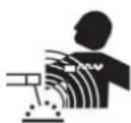
ELECTRIC AND MAGNETIC FIELDS - Can be dangerous to health
- Welders having pacemakers should consult their physician before welding. EMF may interfere with some pacemakers.
- Exposure to EMF may have other health effects which are unknown.
- Welders should use the following procedures to minimize exposure to EMF:
- Route the electrode and work cables together on the same side of your body. Secure them with tape when possible. Do not place your body between the torch and work cables. Never coil the torch or work cable around your body. Keep welding power source and cables as far away from your body as possible.
- Connect the work cable to the workpiece as close as possible to the area being welded.
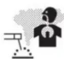
FUMES AND GASES - Can be dangerous to health
- Keep your head out of the fumes.
- Use ventilation, extraction at the arc, or both, to take fumes and gases away from your breathing zone and the general area.
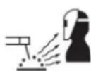
ARC RAYS - Can injure eyes and burn skin
- Protect your eyes and body. Use the correct welding screen and filter lens and wear protective clothing.
- Protect bystanders with suitable screens or curtains.

NOISE - Excessive noise can damage hearing
Protect your ears. Use earmuffs or other hearing protection.

MOVING PARTS - Can cause injuries
- Keep all doors, panels and covers closed and securely in place. Have only qualified people remove covers for maintenance and troubleshooting as necessary. Reinstall panels or covers and close doors when service is finished and before starting engine.

- Stop engine before installing or connecting unit.
- Keep hands, hair, loose clothing and tools away from moving parts.
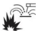
FIRE HAZARD
- Sparks (spatter) can cause fire. Make sure that there are no inflammable materials nearby.
- Do not use on closed containers.
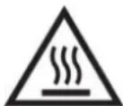
HOT SURFACE - Parts can burn
- Do not touch parts bare handed.
- Allow cooling period before working on equipment.
- To handle hot parts, use proper tools and/or insulated welding gloves to prevent burns.
MALFUNCTION - Call for expert assistance in the event of malfunction.
PROTECT YOURSELF AND OTHERS!

CAUTION!
This product is solely intended for arc welding.

WARNING!
Do not use the power source for thawing frozen pipes.

CAUTION!
Class A equipment is not intended for use in residential locations where the electrical power is provided by the public low-voltage supply system. There may be potential difficulties in ensuring electromagnetic compatibility of class A equipment in those locations, due to conducted as well as radiated disturbances.

natural_image
Simple line drawing of a house with two crossed lines forming an X shape (no text or symbols)
NOTE!
Dispose of electronic equipment at the recycling facility!
In observance of European Directive 2012/19/EC on Waste Electrical and Electronic Equipment and its implementation in accordance with national law, electrical and/or electronic equipment that has reached the end of its life must be disposed of at a recycling facility.
As the person responsible for the equipment, it is your responsibility to obtain information on approved collection stations.
For further information contact the nearest ESAB dealer.

natural_image
Symbol of a trash bin crossed with a diagonal line, no text or numbers presentESAB has an assortment of welding accessories and personal protection equipment for purchase. For ordering information contact your local ESAB dealer or visit us on our website.
2 INTRODUCTION
The Warrior Edge 500 is integrated with a cooling unit and offers a complete multi-process package supporting MIG/MAG, MMA, Live TIG and gouging. It is intended for use in combination with RobustFeed Edge.
The power source is equipped with gateway to connect to the WeldCloud suite of applications, including WeldCloud Productivity for production monitoring and WeldCloud Fleet for managing your fleet of welding equipment.
For more information about the wire feed units, refer to the Instruction manual 0463 773 001.
For more information about WeldCloud, refer to the Quick start guide 0463 778 001.
ESAB accessories for the product can be found in the "ACCESSORIES" chapter of this manual.
2.1 Equipment
The power source is supplied with:
- 5 m (16 ft) 95mm return cable with earth clamp
- 5 m (16 ft) mains cable
- Instruction manual
- Quick start guide
- Safety instruction
3 TECHNICAL DATA
| WARRIOR EDGE 500 | |||
| Mains voltage 380-460 V, ±10%, 3~ 50/60 Hz | |||
| Mains supply S_min | 6.8 MVA | ||
| Primary current I_max | 380 V 400 V 460 V | ||
| MIG/MAG 36 A 36 A 31 A | |||
| MMA 38 A 37 A 32 A | |||
| TIG 29 A 29 A 25 A | |||
| Idle power with fans OFF | 41 W 43 W 43 W | ||
| Setting range (DC) | |||
| MIG/MAG | 16 A/14.8 V - 500 A/39 V | ||
| MMA | 16 A/20.6 V - 500 A/40 V | ||
| TIG | 4 A/10.2 V - 500 A/30 V | ||
| Permissible load at MIG/MAG | |||
| 60% duty cycle | 500 A/ 39 V | ||
| 100% duty cycle | 400 A/ 34 V | ||
| Permissible load at MMA | |||
| 60% duty cycle | 500 A/40 V | ||
| 100% duty cycle | 400 A/36 V | ||
| Permissible load at TIG | |||
| 60% duty cycle | 500 A/30 V | ||
| 100% duty cycle | 400 A/26 V | ||
| Power factor | |||
| at maximum current (MMA) | 0.91 | ||
| MIG/MAG welding | 0.93 | ||
| Efficiency | |||
| at maximum current (MMA) | 89% | ||
| MIG/MAG welding | 88% | ||
| Open-circuit voltage | 55 V | ||
| Operating temperature | -20 to +55 °C | ||
| Transportation temperature | -40 to +80 °C | ||
| Constant sound pressure when idling | < 70 dB (A) | ||
| Dimensions l x w x h | 700×325×680 mm | ||
| Weight | 85 kg (including cooler) | ||
| Insulation class | H | ||
| Enclosure class | IP23 | ||
| Application class | S | ||
| Coolant | ESAB's coolant (0465 720 002) | ||
| Cooling power 1.4 kW | |||
| Cooling volume 4.7 l | |||
| Maximum flow 2 l/min | |||
| Maximum pressure 4.5 bar | |||
Mains supply, \$ min
Minimum short circuit power on the network in accordance with IEC 61000-3-12.
Duty cycle
The duty cycle refers to the time as a percentage of a ten-minute period that you can weld at a certain load without overloading.
Enclosure class
The IP code indicates the enclosure class, i.e. the degree of protection against penetration by solid objects or water.
Equipment marked IP23 is intended for indoor and may be used outdoors if sheltered during precipitation.
Application class
The symbol indicates that the power source is suitable for welding in an environment with an increased risk of electric shock.
4 INSTALLATION
The installation must be carried out by a professional.

CAUTION!
This product is intended for industrial use. In a domestic environment this product may cause radio interference. It is the user's responsibility to take adequate precautions.
4.1 Location
Position the welding power source in such a way that its cooling air inlets and outlets are not obstructed.
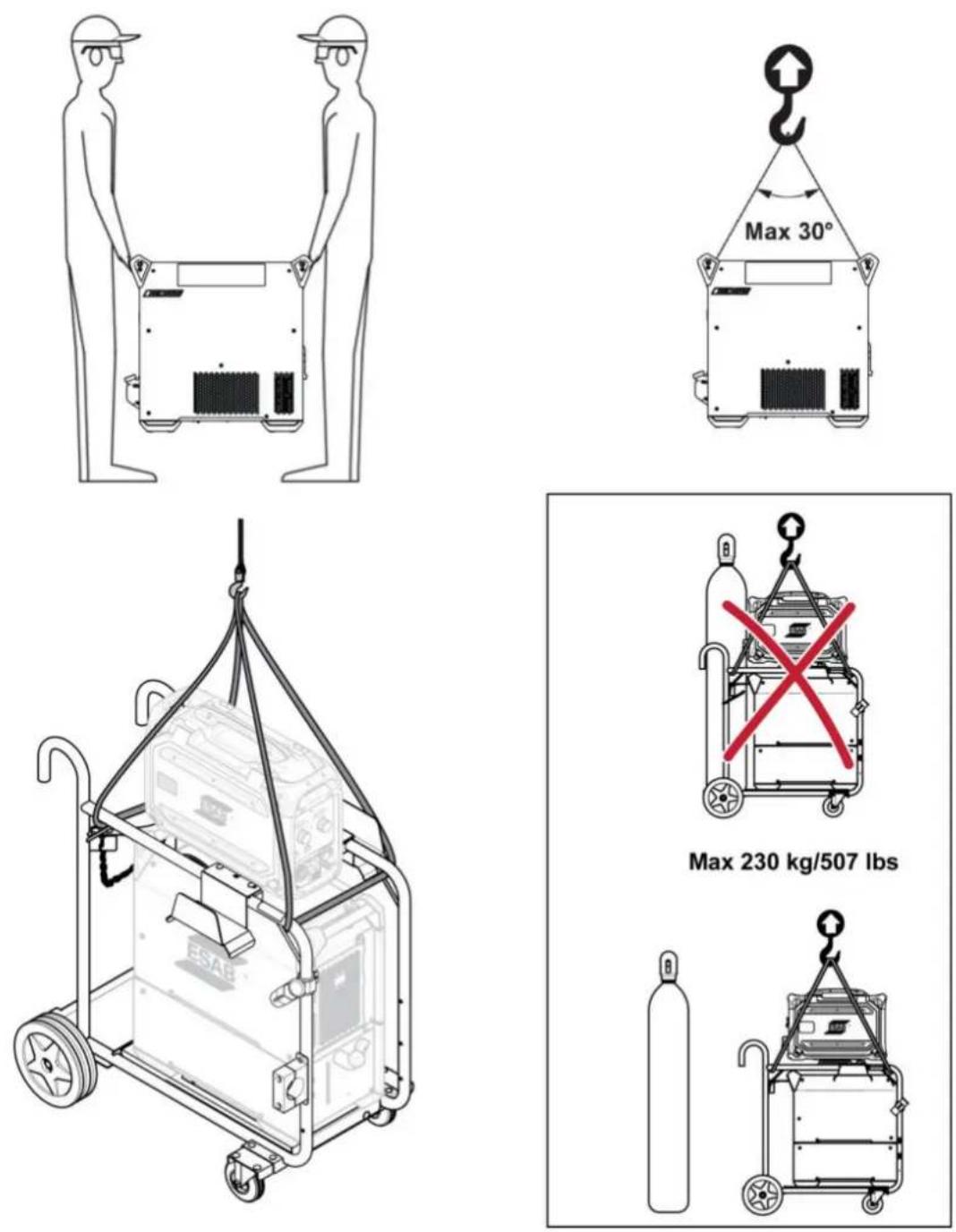
4.2 Lifting instructions
Mechanical lifting must be done with both outer handles.
4.3 Mains supply

NOTE!
Mains supply requirements
This equipment complies with IEC 61000-3-12 provided that the short-circuit power is greater than or equal to S_semin at the interface point between the user's supply and the public system. It is the responsibility of the installer or user of the equipment to ensure, by consultation with the distribution network operator if necessary, that the equipment is connected only to a supply with a short-circuit power greater than or equal to S Refer to the technical data in the TECHNICAL DATA chapter.
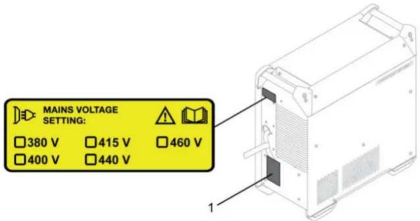
- Rating plate with supply connection data.
4.4 Recommended fuse sizes and minimum cable area
| WARRIOR EDGE 500 | |||
| Mains voltage 380 V | 3~ 50/60 Hz 400 V 3~ | 50/60 Hz 460 V 3~ 50/60 Hz | |
| Mains cable area 4×6 mm2 | 4×6 mm2 | 4×6 mm2 | |
| Maximal currentmax | 38 A 37 A 32 A | ||
| I1eff | |||
| MIG/MAG 29 A 28 A 24 A | |||
| MMA 30 A 29 A 25 A | |||
| TIG 24 A 22 A 19 A | |||
| Fuse | |||
| Anti-surge | 35 A 35 A 35 A | ||
| Type C MCB | 32 A 32 A 32 A | ||

NOTE!
The mains cable areas and fuse sizes as shown above are in accordance with Swedish regulations. For other regions, supply cables must be suitable for the application and meet local and national regulations.
Supply from power generators
The power source can be supplied from different types of generators. However, some generators may not provide sufficient power for the welding power source to operate correctly. Generators with Automatic Voltage Regulation (AVR) or with equivalent or better type of regulation, with rated power ≥ 40 kW, are recommended.
Connection instruction

WARNING!
The mains supply must be disconnected during installation.

WARNING!
Wait until the DC bus capacitors are discharged. The DC bus capacitor discharge time is at least 2 minutes!
The power source is factory set to 400 V AC. If another mains voltage setting is required, the cable on the printed circuit board has to be moved and put in the correct position. Also, the label at the rear of the power source, marked with the mains voltage setting must be updated. This operation must be done by a person who has the appropriate electrical knowledge.
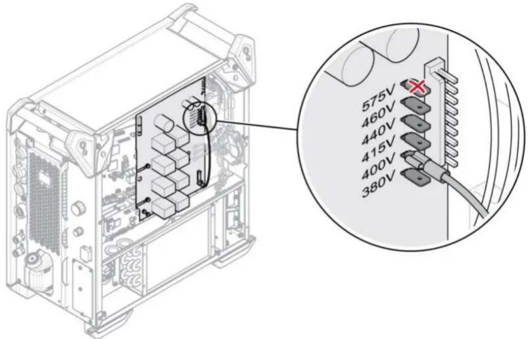

NOTE!
This power source version is designed for a nominal input voltage from 380 to 460 V AC. This means that the hardware to support 575 V input is not available, 575 V tab is not connected.
If the mains cable needs to be changed, the earth connection to the bottom plate and the ferrites must be installed correctly. See the picture below for the installation order of the ferrites, washers, nuts and screws.
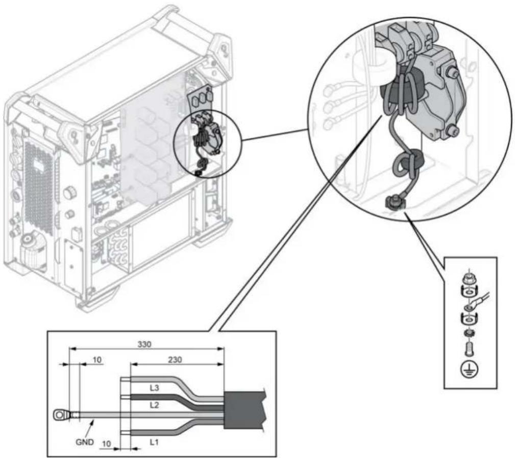
| Connections Cable colour (CE) | |
| L1 Brown | |
| L2 Black | |
| L3 Grey | |
| GND Yellow/Green | |
5 OPERATION
General safety regulations for handling the equipment can be found in the "SAFETY" chapter of this manual. Read it through before you start using the equipment!

NOTE!
When moving the equipment use intended handle. Never pull the cables.

WARNING!
Electric shock! Do not touch the workpiece or the welding head during operation!
5.1 Connections and control devices
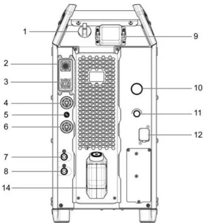
natural_image
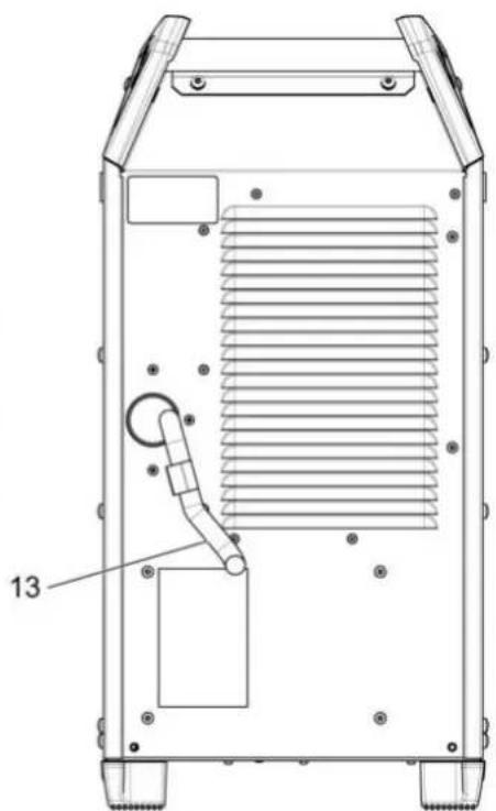
Technical line drawing of a mechanical device with internal ventilation duct and labeled component (13), no readable text or symbols beyond the label.- Mains power supply switch, O/I 8. Connection BLUE for coolant from cooling unit
- Connection for remote control unit 9. USB connection ports
- Power connection to wire feed unit 10. Current/Voltage encoder knob
- Negative welding terminal: Return cable 11. Process selection knob
- Fuse (10 A) for supply voltage for wire feeder2. WeldCloud Ethernet connection unit
- Positive welding terminal: Welding cable 13. Mains cable
- Connection RED for coolant (return) to cooling. Coolant tank unit
5.2 Symbols
 | WeldCloud connection USB | connection  | |
 | Protective earth Position for m ized  | lifting | |
5.3 Connection of welding and return cable
The power source has two outputs, a positive terminal (+) and a negative terminal (-), for connecting welding and return cables.
Connect the return cable to the negative terminal on the power source. Secure the return cable's contact clamp to the work piece and ensure that there is good contact between the work piece and the output for the return cable on the power source.
Recommended maximum current values for connection set cables
At an ambient temperature of +25 °C and normal 10 minutes cycle:
| Cable area | Duty cycle | Voltage loss / 10 m | |
| 100% 60% | |||
| 50 mm2 | 290 320 0.35 | V / 100 A | |
| 70 mm2 | 360 400 0.25 | V / 100 A | |
| 95 mm2 | 430 500 0.19 | V / 100 A | |
At an ambient temperature of +40 °C and normal 10 minutes cycle:
| Cable area | Duty cycle | Voltage loss / 10 m | |
| 100% 60% | |||
| 50 mm2 | 250 280 0.37 | V / 100 A | |
| 70 mm2 | 310 350 0.27 | V / 100 A | |
| 95 mm2 | 370 430 0.20 | V / 100 A | |
Duty cycle
The duty cycle refers to the time as a percentage of a ten-minute period that you can weld at a certain load without overloading.
5.4 Turning the mains power ON/OFF
Turn ON the mains power by turning switch to the "I" position.
Turn the power source OFF by turning the switch to the "O" position.
Regardless the mains supply is interrupted abnormally, or the power source is switched off in the normal manner, the welding data will be stored, so it will be available next time the unit is turned on.
5.5 Fan control
The power source has a time control that means that the fans continue to run for 4 minutes after welding has stopped. The fans start again when welding restarts.
5.6 Usage of cooling unit
ELP (ESAB Logic Pump)
The cooling unit is equipped with detection system called ELP (ESAB Logic Pump), which checks that the coolant hoses are connected. When connecting a liquid cooled torch, cooling starts.

NOTE!
The cooling unit starts as soon as the ELP is activated!
For liquid cooled torches, the cooling unit will start only if the torch cooling hoses are connected to the wire feeder.
When the cooling hoses are disconnected from the wire feeder, the cooling stops immediately.

NOTE!
The cooling unit will be applicable only for MIG/MAG welding.
The power source automatically detects the need of cooling unit based on welding applications and operates the cooling unit accordingly.
When liquid cooled torch is connected, if the coolant temperature exceeds 45 ^ , the cooler fan and pump will start even if there is no welding operation.
5.6.1 Operation of cooling unit after welding
If the coolant temperature is below 55^ C, the cooler fan and pump will continue to run for three minutes and then stop.
If the coolant temperature is at 65^ C or above, the cooler fan and pump will continue to run for seven minutes and then stop.
In a long weld, if the coolant temperature has not decreased to 55^ C within seven minutes, the cooler fan and pump will continue to run for another three minutes and then stop.
5.7 Cooling unit connection
For trouble free operation, it is recommended that the height from the cooling unit to the liquid-cooled torch is 25 m or less.
5.8 Cooling unit pressure controller
The pump has an enclosed pressure relief valve. The valve opens gradually when the pressure is too high. This can occur if a hose is folded, which causes the flow to fail or stop.
5.9 USB Connection
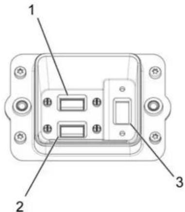
- IoT Gateway USB port 1 3. USB port 3, which enables the user to upgrade
the software and to export the error log report. - IoT Gateway USB port 2
6 CONTROL PANEL
6.1 Overview
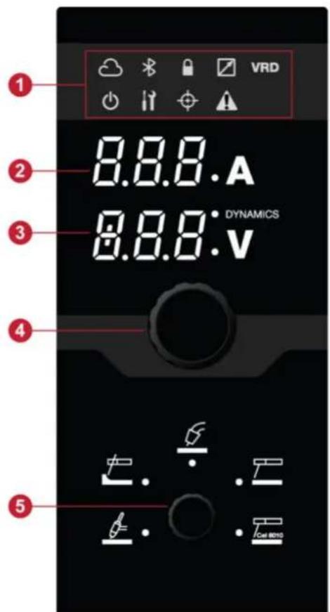
- LED Indicators 4. Current/voltage encoder knob
- Display, shows set or measured current 5. Application selection knob
- Display, shows set or measured voltage/dynamics
6.2 LED indicators description
| Indicator Description | |
 | WeldCloudAn online management system that connects welding power supplies to a software platform that manages data to be analysed for maximum productivity.WeldCloud productivity provides the production manager tools to improve welding productivity and increase traceability by keeping track of each weld, operator, part number and more.The indicator is lit in green when it is connected. |
 | VRD (Voltage Reducing Device)The VRD function ensures that the open-circuit voltage does not exceed 35 V when welding is not being carried out. The VRD function must be activated by a qualified service technician, by means of Edge ESAT (ESAB Software Administration Tool, a kit for technical service including a software to manage settings, update of software etc.).The VRD function is blocked when the system senses that welding has started.When VRD function is active, the indicator is lit in green. |
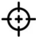 | TRUEARC compensateTo achieve a good welding result, the arc voltage is a crucial factor. In MIG/MAG welding, the power source is prepared to sense the arc voltage in the wire feeder. Prerequisite for this functionality is that an ESAB wire feeder and an ESAB interconnection cable is used.In compensation mode, when the torch is triggered on the workpiece (avoid wire contact), it measures the inductance and resistance to compensate for the voltage drop in the interconnection cable, torch and return cable.The indicator is lit in yellow when compensation is required and it blinks during the compensation process. If the compensation process is a success, the indicator is lit in green. |
 | Warning/ErrorWarningThe indicator is lit in yellow and displays an "Err" message. If warning occurs, completion of ongoing weld is possible, but start of a new weld is prevented as long as the warning remains.ErrorThe indicator is lit in red and displays an "Err" message. The ongoing welding is stopped as long as the error remains. |
 | LockGreen - This indicates when the system has limited access or Job limits are active.Red - This indicates the system is locked, and to be able to use the system, it is required to unlock.Red (blink) - This indicates when the user is trying to access the restricted features. |
6.3 Functions and symbols
6.3.1 TIG welding
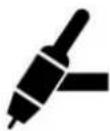
TIG welding melts the metal of the workpiece, with an arc initiated from a non-consuming tungsten electrode. The weld pool and electrode are protected by shielding gas.
For TIG welding, the welding power source shall be supplemented with:
• a TIG torch with gas valve
• an argon gas cylinder
• an argon gas regulator
• tungsten electrode
This power source performs Live TIG start (TIG Live).
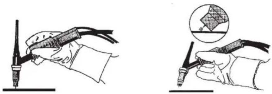
The tungsten electrode is placed against the workpiece. When lifted away from workpiece the arc is struck at a limited current level.
With arc air gouging, a special electrode comprising a carbon rod with a copper casing is used.
An arc is formed between the carbon rod and the workpiece, which melts the material. Compressed air is supplied so that the melted material is blown away.
For arc air gouging the power source shall be supplemented with:
- ARCAIR torches
- return cable with clamp
- air pressure
Recommended voltage setting for ARCAIR gouging electrodes
| Electrode size | in 1/8 | 5/32 | 3/16 | 1/4 | 5/16 | 3/8 | ||||
| mm | 3.2 | 4.0 | 4.8 | 6.4 | 7.9 | 9.5 | ||||
| Voltage | V | 35-38 | 36-40 | 38-42 | 40-46 | 44-50 | 46-54 | |||

NOTE!
The minimum and maximum settings are starting points for the rods indicated, with relatively clean metal, an acceptable gouge groove should be expected. These specific recommendations are based on the result of test carried out on A36/ASME mild steel.
For different types of metal, adjust the volt setting and air flow for better performance.
For any gouging issues other than performance, see the TROUBLESHOOTING section.
6.3.3 MMA welding
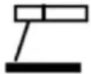
MMA welding may also be referred to as welding with coated electrodes. Striking the arc melts the electrode, and its coating forms protective slag.
For MMA welding the power source shall be supplemented with:
- welding cable with electrode holder
- return cable with clamp
6.3.4 MMA cel 6010 welding
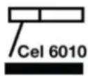
Optimized arc characteristic for cellulosic electrodes such as 6010 and similar.
6.3.5 MIG/MAG

An arc melts a continuously supplied wire. The weld pool is protected by shielding gas.
For MIG/MAG welding, the power source shall be supplemented with:
- wire feed unit
- welding torch
- connection cable between power source and wire feed unit
- gas cylinder
- return cable with clamp
6.4 Measured or set values

Measured or set voltage
Measured or set value in the display for arc voltage V is an average arithmetic value.

Measured or set amperage
Measured or set value in the display for welding current A is an average arithmetic value.
7 MAINTENANCE

WARNING!
The mains supply must be disconnected during cleaning and maintenance.

CAUTION!
Only persons with the appropriate electrical knowledge (authorised personnel) may remove the safety plates.

CAUTION!
The product is covered by manufacturer's warranty. Any attempt to carry out repair work by non-authorised service centers or personnel will invalidate the warranty.

NOTE!
Regular maintenance is important for safe and reliable operation.

NOTE!
Perform maintenance more often during severe dusty conditions.
Before each use - make sure that:
• Product and cables are not damaged
• The torch is clean and not damaged
7.1 Routine maintenance
Maintenance schedule during normal conditions. Check equipment prior to every use.
| Interval Area to maintain | |||
| Every 3 months | 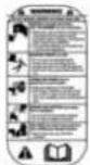 Clean or replace unreadable labels. Clean or replace unreadable labels. | 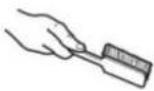 Clean weld terminals. Clean weld terminals. |  Check or replace weld cables. Check or replace weld cables. |
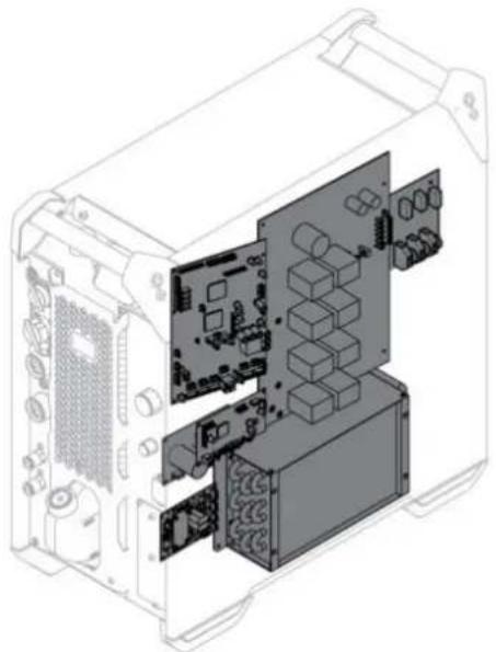
| Every 12 months or depending on environmental conditions (by authorised service technician) |  Clean inside equipment. Use dry compressed air with 4 bar pressure. Clean inside equipment. Use dry compressed air with 4 bar pressure. | ||
7.1.1 Cleaning procedure
To maintain the performance and increase the lifetime of the power source it is mandatory to clean the product regularly. How often depends on:
• the welding process
- the arc time
• the working environment
• the surrounding environment, that is grinding etc
Tools needed for the cleaning procedure:
• torx screwdriver, T25 and T30
- dry compressed air at a pressure of 4 bar
- protective equipment like ear plugs, safety glasses, masks, gloves and safety shoes

CAUTION!
Make sure that the cleaning procedure is done in a suitable prepared workspace.
natural_image
Technical line drawing of an internal computer chassis showing internal components like CPU, memory, and drive slots (no text or labels)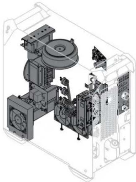
natural_image
Technical line drawing of an internal electronic device with visible components and wiring (no text or symbols)
CAUTION!
The cleaning procedure should be carried out by authorised service technician.
- Disconnect the power source from the mains supply.

WARNING!
Wait until the DC bus capacitors are discharged. The DC bus capacitor discharge time is at least 2 minutes!
- Remove the side panels on the power source.
- Remove the top panel on the power source.
-
Remove the plastic cover between the heat sink and fan.
-
Clean the power source with dry compressed air (4 bar) as follows:
-
The upper rear part.
- From the rear panel through the secondary heat sink.
- The inductor, transformer and current sensor.
- The power components side, from the rear side behind PCB 15AP1.
• The PCBs at both sides. - Current brake resistors
-
Radiator and fans
-
Make sure that there is no dust left on any part of the power source.
- Install the plastic cover between the heat sink and the fan and make sure it is correctly fitted against the heat sink.
- Reassemble the power source after cleaning and perform testing according to IEC 60974-4.
Follow the procedure in section “After repair, inspection and test” in the Service manual.
7.2 Cooling unit
Dust, grinding, swarf etc
The airstream through the cooling unit carries particles that become trapped in the cooling element, particularly in dirty working environments. This results in reduced cooling capacity.
The coolant system
The recommended coolant must be used in the system. Otherwise, clumps that block the pump, coolant connections or elements can be created. Flushing can only be performed via red coolant connection. Then drain the tank manually, i.e. empty via the tank's filling hole.
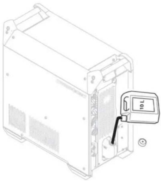
7.2.1 Filling the coolant
Use only ESAB's ready mixed coolant. See chapter "ACCESSORIES".
- Fill with coolant. (The fluid level must not exceed the upper marking, but neither must it be below lower marking.)

CAUTION!
The coolant must be handled as chemical waste.

NOTE!
Coolant must be topped up if connecting a welding torch or coolant hoses that are 5 m in length or longer. When adjusting the coolant level by topping up, the coolant hoses do not need to be disconnected.
natural_image
Line drawing of a computer chassis with a digital display showing 10 L (no text or symbols on the device itself)8 EVENT CODES
Event codes are used in order to indicate and identify an error in the equipment. Event codes provide information about the equipment.
Fault log
All faults that occur when using the welding equipment are documented as error messages in the fault log. When the fault log is full, the oldest message will automatically erase when the next fault occurs.
The most recent fault message is displayed on the control panel. The entire fault log as well as corrective action can be read on the internal control panel.
List of event codes
The control panel displays an event code with three digits and the first digit indicates the type of event. The type of event (first digit of the event code) are as follows:
0 = System 1 = Communication 2 = Power source
3 = Wire feed unit
4 = Cooling unit
6 = Gas unit
7 = External

NOTE!
The last two digits indicate the event description at which the user can take corrective action. If the error code persist or any other code is shown, contact a service technician.
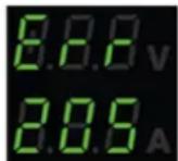
The example presented in the graphic to the left, indicates that the Supply voltage fault in the power source.
x01 | Application fault
This event code is displayed due to one of the following:
• 001 - Application checksum error.
- Acknowledge by pressing any buttons on the control panel.
- Restart the system.
x05 Supply voltage fault
This event code is displayed due to one of the following:
• 205 - Mains over/under voltage or phase error.
- Make sure that the supply voltage is stable.
- Restart the system.
x06 | Temperature fault
This event code is displayed due to one of the following:
• 406 - Return coolant temperature warning/error.
• 206 - Overtemperature.
• 306 - High wire motor temperature warning/error.
For 406 and 206 - Return coolant temperature warning/error and Overtemperature, perform the following actions:
- Make sure that the cooling air inlets or outlets are not blocked or clogged by dirt.
- Check the duty cycle being used, to make sure that the equipment is not being overloaded.
- Wait until the temperature cools down.
For 306 - High wire motor temperature warning/error, perform the following actions:
- Check the liner, clean using pressurized air. Replace the liner if damaged or worn out.
- Check the wire pressure setting and adjust if needed.
- Check the drive rolls for wear and replace if needed.
- Make sure the filler metal spool can rotate without much resistance. Adjust the brake hub if needed.
- Restart the system.
- If the error persists, check the liner, clean using pressurized air and replace the liner if damaged or worn out.
- If the error persists despite performing these actions, try replacing the torch.
x08 | Battery warning
This event code is displayed due to one of the following:
• 208 - RTC/SRAM battery low warning.
- Make sure that the polarity (+, - terminals) of the battery is right.
- Contact authorised service technician to replace the battery.
x09 | Internal voltage error
This event code is displayed due to one of the following:
• 209 - Internal over/under voltage error.
- Restart the system.
- Contact authorised person to check the main inputs.
x11 | Wire feed speed fault
This event code is displayed due to one of the following:
• 311 - Wire saturation warning/error.
• 311 - Wire motor start/work current error.
- Check the correct liners/contact tip/torch used for types of welding wires.
- Check the torque tension in the break hub.
- Make sure that the wire feed speed control is dust free and rotate.
- Acknowledge by pressing any buttons on the control panel.
- Contact service technician to check drive motor.
x14 | Communication fault
This event code is displayed due to one of the following:
• 114 - Weld control communication error.
• 114 - Internal communication warning.
• 114 - Connection to main control lost.
• 114 - Fieldbus interface lost.
- Check that all the equipment is correctly connected.
- Acknowledge by pressing any buttons on the control panel.
- Do not turn OFF the system and contact service technician.
x15 | Short circuit detected
This event code is displayed due to one of the following:
• 215 - Weld contact detected at startup.
- Make sure that the welding cables are properly installed of the weld terminals.
- Acknowledge by pressing any buttons on the control panel.
- Contact service technician.
x16 | High open circuit voltage fault
This event code is displayed due to one of the following:
• 216 - Voltage sensor lost.
• 216 - OCV level is too high.
• 216 - Current brake module lost.
• 216 - Current brake function error.
- In case of voltage sensor lost, contact service technician. Otherwise restart the system.
x17 | Lost contact with another unit
This event code is displayed due to one of the following:
• 017 - Mandatory node missing.
• 017 - Critical node lost.
- Check the cable connections between the subsystem (wire feeder and power source).
- Acknowledge by pressing any buttons on the control panel.
- Contact service technician.
x18 Internal memory fault
This event code is displayed due to one of the following:
• 018 - Partition data storage warning.
- Make sure that network connection is stable with WeldCloud and acknowledge.
x19 | Memory fault
This event code is displayed due to one of the following:
• 019 - Parameter memory read/write error.
• 019 - Log read/write error.
- Restart the system.
- Contact service technician.
x20 | User management fault
This event code is displayed due to one of the following:
• 020 - No valid job available.
- Make sure that the predefined jobs are saved by admin.
x25 Incompatible units
This event code is displayed due to one of the following:
- 025 - System communication version mismatch warning/error.
- 025 - Power converter control module version not valid.
-
025 - Power converter control module power capacity unknown.
-
Contact service technician.
- Make sure that the software version should be similar for each connected nodes.
- Connect the correct wire feed unit and restart.
x26 | Timing fault
This event code is displayed due to one of the following:
• 026 - Watchdog timeout.
• 026 - Process control error.
- Restart the system (recycle power).
- Acknowledge by pressing any buttons on the control panel.
- Contact service technician.
x29 | No coolant flow
This event code is displayed due to one of the following:
• 429 - ELP off during welding.
- Check the coolant hose connections and acknowledge.
x31 | Gas pressure fault
This event code is displayed due to one of the following:
• 631 - Gas input pressure warning/error.
- Check gas input pressure.
- Select the appropriate setting of gas flow in control panel.
- Acknowledge by pressing any buttons on the control panel.
- Contact service technician.
x32 | Gas flow fault
This event code is displayed due to one of the following:
• 632 - Gas saturation warning/error.
• 632 - No gas out error.
- Check gas input pressure.
- Check the gas hoses, gas pressure regulator and connectors and acknowledge.
- Select the appropriate setting of gas flow in control panel.
x33 | USB fault
This event code is displayed due to one of the following:
• 033 - USB high current.
• 033 - USB read/write error.
- Make sure that the USB is in good working condition and configured properly.
- Contact service technician.
x35 Software runtime fault
This event code is displayed due to one of the following:
• 035 - Message allocation error.
• 035 - Driver message allocation error.
• 035 - Event queue overflow.
• 035 - Failed to start microservices.
- Restart the system.
- Contact service technician.
x36 | External stop
This event code is displayed due to one of the following:
• 736 - Fieldbus quickstop.
• 736 - Fieldbus superquickstop.
- Acknowledge by pressing any buttons on the control panel.
- Restart.
9 TROUBLESHOOTING
Perform these checks and inspections before sending for an authorised service technician.
Check that the mains voltage is disconnected before starting any type of repair action.
| Type of fault Corrective action | |
| No arc Check that the mains | power supply switch is turned ON. |
| Check that the mains, welding and return cables are correctly connected. | |
| Check that the correct current value is set. | |
| Check the mains power supply fuses. | |
| The welding current is interrupted during welding | Check whether the thermal protection trip has operated (indicated by LED on Overtemperature indicator in control panel). |
| Check the mains supply fuses. | |
| The thermal protection trips frequently | Make sure that you are not exceeding the rated data for the power source (i.e. that the unit is not being overloaded). |
| Check that the ambient temperature is not above the one for the duty cycle 40 °C/104 °F. | |
| Poor welding performance C | Check that the welding current supply and return cables are correctly connected. |
| Check that the correct current value is set. | |
| Check that the correct welding wires are being used. | |
| Check the main power supply fuses. | |
| Poor cooling effect Clean the | cooling element using compressed air. |
| Check the coolant level. | |
| Check that the ambient temperature is not above the one for the duty cycle 40 °C/104 °F. | |
| Intermittent gouging stops or contact between carbon and metal lost | Air pressure is too high. Reduce the air pressure. |
| Check the air pressure whether it is set to the recommended value. Check the manual of the torch used. | |
| Carbon deposit on the gouge metal | Air pressure is too low. Turn on air before striking the arc and air should flow between the electrode and the workpiece. |
| Check the air pressure whether it is set to the recommended value. Check the manual of the torch used. | |
| No arc during start or erratic arc during gouging | Check whether the voltage is set to the recommended value. |
| Intermittent arc action resulting in an irregular groove surface or copper deposition on the metal plate | Check whether the voltage is set to the recommended value. |
10 ORDERING SPARE PARTS

CAUTION!
Repair and electrical work should be performed by an authorised ESAB service technician. Use only ESAB original spare and wear parts.
Warrior Edge 500 is designed and tested in accordance with the international and European standards EN IEC 60974-1, EN IEC 60974-2 and EN IEC 60974-10 Class A, Canadian standards CAN/CSA 60974-1, CAN/CSA 60974-2 and US standards ANSI/IEC 60974-1, ANSI/IEC 60974-2.
On completion of service or repair work, it is the responsibility of the person(s) performing the work to ensure that the product still complies with the requirements of the above standards.
Spare parts and wear parts can be ordered through your nearest ESAB dealer, see esab.com. When ordering, please state product type, serial number, designation and spare part number in accordance with the spare parts list. This facilitates dispatch and ensures correct delivery.
11 CALIBRATION AND VALIDATION

WARNING!
Calibration and validation should be performed by a trained service technician, possessing sufficient training in welding and measurement technology. The technician should have knowledge of hazards that may occur during welding and measurement and should take necessary protective actions!
11.1 Measurement methods and tolerances
When calibrating and validating, the reference measuring instrument must use the same measuring method in the DC range (averaging and rectification of the measured values). A number of measurement methods are used for reference instruments, e.g. TRMS (True Root Mean Square), RMS (Root-Mean-Square) and rectified arithmetic mean. Warrior Edge 500 uses the rectified arithmetic mean value and should therefore be calibrated against a reference instrument using the rectified arithmetic mean value.
In the field application it will occur that a measuring device and a Warrior Edge 500 may display different values even though both systems are validated and calibrated. This is due to the measurement tolerances and the method of measurement of the two measurement systems. This can result in a total deviation up to the sum of both measurement tolerances. If the measurement method differ (TRMS, RMS or rectified arithmetic mean), significantly larger deviations are to be expected!
The ESAB Warrior Edge 500 welding power source presents the measured value in rectified arithmetic mean and should therefore not show any significant differences compared to other ESAB welding equipment, due to the measurement method.
11.2 Requirements, specifications and standards
Warrior Edge 500 is designed to meet the accuracy for indication and meters required by IEC/EN 60974-14, by definition Standard grade.
Calibration accuracies of displayed value
Arc voltage ±1.5 V (Umin–U2) under load, resolution 0.25 V (Theoretical measuring range in a Warrior Edge 500 system is 0.25–199 V.)
Welding current ±2.5% of I2 max according to rating plate of the unit under test, resolution 1 A. The measuring range is specified by the rating plate on the used Warrior Edge 500 welding power source.
Recommended method and applicable standard
ESAB recommend calibration and validation to be executed according to IEC/EN 60974-14 (unless another way of execution is communicated from ESAB).
APPENDIX
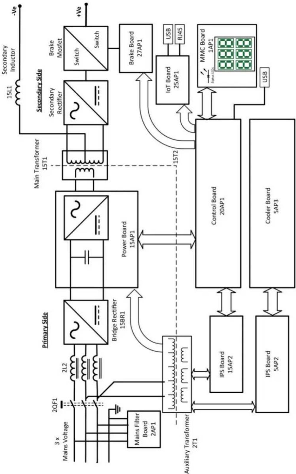
WIRING DIAGRAM
flowchart
graph TD
    A["3 x Mains Voltage"] --> B["2QF1"]
    B --> C["2L2"]
    C --> D["Primary Side"]
    D --> E["Bridge Rectifier 15BR1"]
    E --> F["Power Board 15AP1"]
    F --> G["Main Transformer 15T1"]
    G --> H["Secondary Rectifier"]
    H --> I["Switch/Switch"]
    I --> J["+Ve"]
    K["Auxiliary Transformer 2T1"] --> L["IPS Board 15AP2"]
    L --> M["Control Board 20AP1"]
    M --> N["Cooler Board 5AP3"]
    N --> O["IPS Board 5AP2"]
    O --> P["Control Board 20AP1"]
    P --> Q["IoT Board 25AP1"]
    Q --> R["Motor Control"]
    S["MSI"] --> T["Motor Control Board"]
    U["USB"] --> V["Motor Control Board"]
    W["MMC Board 1AP1"] --> X["Motor Control Board"]
    Y["Brake Mosfet"] --> Z["Brake Mosfet Switch"]
    AA["3x Mains Voltage"] --> AB["2QF1"]
    AC["15L1 Secondary Inductor"] --> AD["-Ve"]
    AE["15T2"] --> AF["15T1"]
    AG["15T2"] --> AH["15T1"]
    AI["USB"] --> AJ["Motor Control Board"]
    AK["RJ45"] --> AL["Motor Control Board"]
ORDERING NUMBERS
natural_image
Technical line drawing of a computer control unit with visible ports, buttons, and ventilation grilles (no text or labels)| Ordering number | Denomination Type Notes | ||
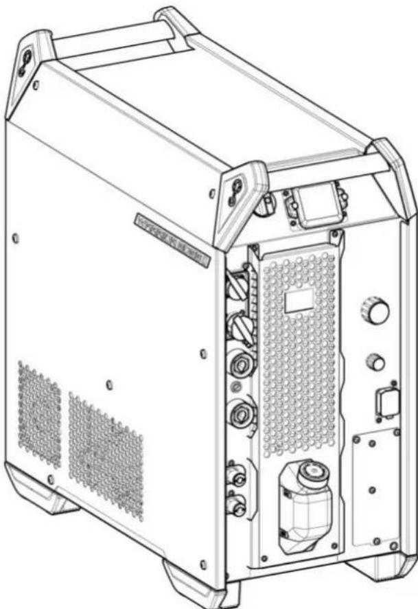
| 0446 300 880 Power | source Warrior Edge | 500 CX I 380-460 V, CE | |
| 0446 300 884 Power | source Warrior Edge | 500 CX II 380-460 V, CE | Including SPEED |
| 0463 772 * Instruction manual | |||
| 0463 844 001 Service manual | |||
| 0463 843 001 Spare parts list | |||
The three last digits in the document number of the manual show the version of the manual. Therefore they are replaced with * here. Make sure to use a manual with a serial number that corresponds with the product, see the front page of the manual.
Technical documentation is available on the Internet at: www.esab.com
ACCESSORIES
| 0446 600 880 RobustFeed Edge BX with EURO connector, torch cooling system and NFC. | 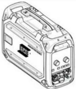 | |
| 0446 600 881 RobustFeed Edge CX with EURO connector, torch cooling system, NFC, heater and digital gas control. | ||
| 0349 313 450 Trolley, compatible with RobustFeed Edge and Warrior Edge 500For assembly instruction, refer to document 0463 357 102 | 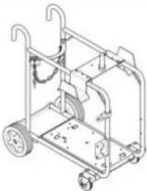 | |
| 0465 720 002 ESAB ready mixed coolant (10 l/2.64 gal)Use of any other cooling liquid than the prescribed one might damage the equipment.In case of such damage, all warranty undertakings from ESAB cease to apply. | 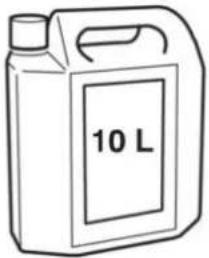 | |
| 0465 416 880 Edge wheel kitFor assembly instruction, refer to document 0463 360 101 | 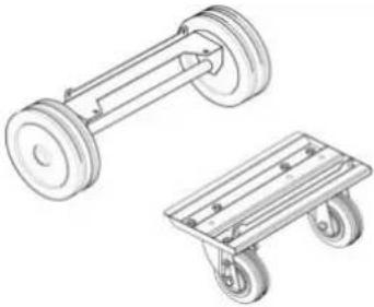 | |
| Interconnection cable with pre-assembled strain relief, Air cooled, 70 mm | ||
| 0446 310 880 2 | 3 m (7 ft) | 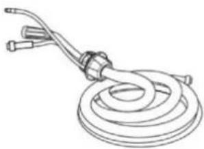 |
| 0446 310 881 5 | m (16 ft) | |
| 0446 310 882 10 | m (33 ft) | |
| 0446 310 883 15 | m (49 ft) | |
| 0446 310 884 20 | m (66 ft) | |
| 0446 310 885 25 | m (82 ft) | |
| 0446 310 886 35 | m (115 ft) | |
| 0446 310 887 50 | m (164 ft) | |
| Interconnection cable with pre-assembled strain relief, Liquid cooled, 70 mm | ||
| 0446 310 890 2 | 3 m (7 ft) | 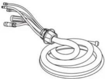 |
| 0446 310 891 5 | m (16 ft) | |
| 0446 310 892 10 | m (33 ft) | |
| 0446 310 893 15 | m (49 ft) | |
| 0446 310 894 20 | m (66 ft) | |
| 0446 310 895 25 | m (82 ft) | |
| 0446 310 896 35 | m (115 ft) | |
| Interconnection cable with pre-assembled strain relief, Air cooled, 95 mm | ||
| 0446 310 980 2 | 3 m (7 ft) | 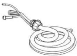 |
| 0446 310 981 5 | m (16 ft) | |
| 0446 310 982 10 | m (33 ft) | |
| 0446 310 983 15 | m (49 ft) | |
| 0446 310 984 20 | m (66 ft) | |
| 0446 310 985 25 | m (82 ft) | |
| 0446 310 986 35 | m (115 ft) | |
| 0446 310 987 50 | m (164 ft) | |
| Interconnection cable with pre-assembled strain relief, Liquid cooled, 95 mm | ||
| 0446 310 990 2 | 3 m (7 ft) | 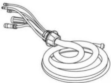 |
| 0446 310 991 5 | m (16 ft) | |
| 0446 310 992 10 | m (33 ft) | |
| 0446 310 993 15 | m (49 ft) | |
| 0446 310 994 20 | m (66 ft) | |
| 0446 310 995 25 | m (82 ft) | |
| 0446 310 996 35 | m (115 ft) | |
A WORLD OF PRODUCTS AND SOLUTIONS.
natural_image
World map outline showing continents and oceans (no text or labels)For contact information visit http://esab.com
ESAB AB, Lindholmsallén 9, Box 8004, 402 77 Gothenburg, Sweden, Phone +46 (0) 31 50 90 00
- Instruction manual
- EU DECLARATION OF CONFORMITY
- According to:
- Type of equipment
- Type designation
- Brand name or trademark
- Manufacturer or his authorised representative established within the EEA
- Additional Information:
- Place/Date
- Signature
- SAFETY 5
- INTRODUCTION 9
- TECHNICAL DATA 10
- INSTALLATION 12
- OPERATION 17
- CONTROL PANEL 21
- MAINTENANCE 25
- EVENT CODES 29
- SAFETY
- Meaning of symbols
- DANGER!
- WARNING!
- CAUTION!
- Safety precautions
- If equipped with ESAB cooler
- ELECTRIC SHOCK - Can kill
- ELECTRIC AND MAGNETIC FIELDS - Can be dangerous to health
- FUMES AND GASES - Can be dangerous to health
- ARC RAYS - Can injure eyes and burn skin
- NOISE - Excessive noise can damage hearing
- MOVING PARTS - Can cause injuries
- FIRE HAZARD
- HOT SURFACE - Parts can burn
- NOTE!
- Dispose of electronic equipment at the recycling facility!
- INTRODUCTION
- Equipment
- Duty cycle
- Enclosure class
- Application class
- INSTALLATION
- Location
- Lifting instructions
- Mains supply
- Mains supply requirements
- Recommended fuse sizes and minimum cable area
- Supply from power generators
- Connection instruction
- OPERATION
- Connections and control devices
- Symbols
- Connection of welding and return cable
- Recommended maximum current values for connection set cables
- Turning the mains power ON/OFF
- Fan control
- Usage of cooling unit
- ELP (ESAB Logic Pump)
- Operation of cooling unit after welding
- Cooling unit connection
- Cooling unit pressure controller
- USB Connection
- CONTROL PANEL
- Overview
- LED indicators description
- Functions and symbols
- TIG welding
- MMA welding
- MMA cel 6010 welding
- MIG/MAG
- Measured or set values
- MAINTENANCE
- Routine maintenance
- Cleaning procedure
- Cooling unit
- Dust, grinding, swarf etc
- The coolant system
- Filling the coolant
- EVENT CODES
- Fault log
- List of event codes
- x01 | Application fault
- x05 Supply voltage fault
- x06 | Temperature fault
- x08 | Battery warning
- x09 | Internal voltage error
- x11 | Wire feed speed fault
- x14 | Communication fault
- x15 | Short circuit detected
- x16 | High open circuit voltage fault
- x17 | Lost contact with another unit
- x18 Internal memory fault
- x19 | Memory fault
- x20 | User management fault
- x25 Incompatible units
- x26 | Timing fault
- x29 | No coolant flow
- x31 | Gas pressure fault
- x32 | Gas flow fault
- x33 | USB fault
- x35 Software runtime fault
- x36 | External stop
- TROUBLESHOOTING
- ORDERING SPARE PARTS
- CALIBRATION AND VALIDATION
- Measurement methods and tolerances
- Requirements, specifications and standards
- Calibration accuracies of displayed value
- Recommended method and applicable standard
- APPENDIX
- WIRING DIAGRAM
- ORDERING NUMBERS
- A WORLD OF PRODUCTS AND SOLUTIONS.
Brand : Esab
Model : Warrior Edge 500 CX
Category : Welding machine