Vigor AP 1000C - Access Point Draytek - Free user manual and instructions
Find the device manual for free Vigor AP 1000C Draytek in PDF.


| Product Type | Access Point |
| Brand | Draytek |
| Model | Vigor AP 1000C |
| Dimensions | 200 x 200 x 35 mm |
| Weight | 500 g |
| Power Supply | 12V DC, 1A (PoE support) |
| Power Consumption | 12W max |
| Wireless Standards | IEEE 802.11a/b/g/n/ac |
| Frequency Bands | 2.4 GHz and 5 GHz |
| Max Data Rate | Up to 1200 Mbps (300 + 867) |
| Ethernet Ports | 1 x Gigabit Ethernet (PoE in) |
| Antennas | 2 x external dual-band antennas |
| Security | WPA2-PSK, WPA3, MAC filtering, rogue AP detection |
| Management | Web GUI, CLI, SNMP, VigorACS management |
| Additional Features | Multiple SSID, VLAN, guest network, load balancing |
| Mounting | Ceiling/wall mountable |
| LED Indicators | Power, LAN, WLAN, Signal |
| Operating Temperature | 0°C to 40°C |
| Humidity | 10% to 90% non-condensing |
| Maintenance | Clean with a dry cloth; avoid moisture |
| Spare Parts | Not available separately |
| Repairability | No user-replaceable parts |
| Warranty | 2 years |
Frequently Asked Questions - Vigor AP 1000C Draytek
User questions about Vigor AP 1000C Draytek
0 question about this device. Answer the ones you know or ask your own.
Ask a new question about this device
Download the instructions for your Access Point in PDF format for free! Find your manual Vigor AP 1000C - Draytek and take your electronic device back in hand. On this page are published all the documents necessary for the use of your device. Vigor AP 1000C by Draytek.
USER MANUAL Vigor AP 1000C Draytek
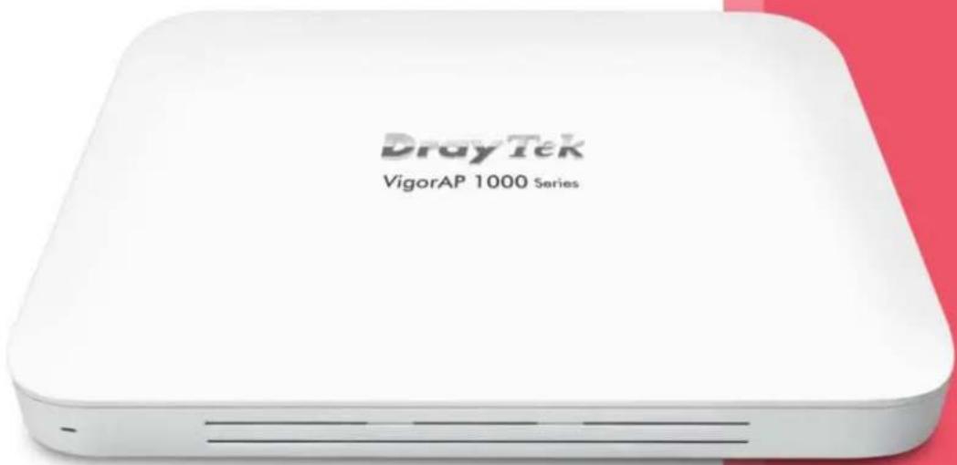
802.11ac Ceiling-mount AP
USER'S GUIDE
VigorAP 1000C
802.11ac Ceiling-mount AP
User's Guide
Version: 1.6
Firmware Version: V1.4.6
Date: August 4, 2023
Intellectual Property Rights (IPR) Information
Copyrights
© All rights reserved. This publication contains information that is protected by copyright. No part may be reproduced, transmitted, transcribed, stored in a retrieval system, or translated into any language without written permission from the copyright holders.
Trademarks
The following trademarks are used in this document:
- Microsoft is a registered trademark of Microsoft Corp.
Windows, Windows 10, 11 and Explorer are trademarks of Microsoft Corp.
Apple and Mac OS are registered trademarks of Apple Inc.
Other products may be trademarks or registered trademarks of their respective manufacturers.
Safety Instructions and Approval
Safety Instructions
Read the installation guide thoroughly before you set up the modem.
The modem is a complicated electronic unit that may be repaired only be authorized and qualified personnel. Do not try to open or repair the modem yourself.
Do not place the modem in a damp or humid place, e.g. a bathroom.
The modem should be used in a sheltered area, within a temperature range of +5 to +40 Celsius.
Do not expose the modem to direct sunlight or other heat sources. The housing and electronic components may be damaged by direct sunlight or heat sources.
- Do not deploy the cable for LAN connection outdoor to prevent electronic shock hazards.
Do not power off the device when saving configurations or firmware upgrades. It may damage the data in a flash. Please disconnect the Internet connection on the device before powering it off when a TR-069/ ACS server manages the device.
- Keep the package out of reach of children.
- When you want to dispose of the modem, please follow local regulations on conservation of the environment.
Warranty
We warrant to the original end user (purchaser) that the modem will be free from any defects in workmanship or materials for a period of two (2) years from the date of purchase from the dealer. Please keep your purchase receipt in a safe place as it serves as proof of date of purchase. During the warranty period, and upon proof of purchase, should the product have indications of failure due to faulty workmanship and/or materials, we will, at our discretion, repair or replace the defective products or components, without charge for either parts or labor, to whatever extent we deem necessary tore-store the product to proper operating condition. Any replacement will consist of a new or re-manufactured functionally equivalent product of equal value, and will be offered solely at our discretion. This warranty will not apply if the product is modified, misused, tampered with, damaged by an act of God, or subjected to abnormal working conditions. The warranty does not cover the bundled or licensed software of other vendors. Defects which do not significantly affect the usability of the product will not be covered by the warranty. We reserve the right to revise the manual and online documentation and to make changes from time to time in the contents hereof without obligation to notify any person of such revision or changes.
Be a Registered Owner
Web registration is preferred. You can register your Vigor router via https://myvigor.draytek.com.
Firmware & Tools Updates
Due to the continuous evolution of DrayTek technology, all modems will be regularly upgraded. Please consult the DrayTek web site for more information on newest firmware, tools and documents. https://www.draytek.com
Table of Contents
Chapter I Installation ......VII
I-1 Introduction....1
I-1-1 LED Indicators and Connectors 2
I-2 Hardware Installation....4
I-3 Network IP Configuration....8
I-3-1 Windows 10 IP Address Setup ....8
I-4 Accessing to Web User Interface 11
I-5 Changing Password 14
I-6 Dashboard 15
I-7 Quick Start Wizard 16
I-7-1 Settings for Access Point.... 17
I-7-2 Settings for Mesh Root.... 20
I-7-3 Settings for Mesh Node 25
I-7-4 Settings for Range Extender 26
Chapter II Connectivity .... 31
II-1 Operation Mode.... 32
II-2 General Concepts for Wireless LAN 34
II-3 Wireless LAN (2.4GHz/5GHz/5GHz-2) Settings for AP Mode 37
II-3-1 General Setup.... 38
II-3-2 Security 41
II-3-3 Access Control 44
II-3-4 WPS 45
II-3-5 Advanced Setting 47
II-3-6 AP Discovery 49
II-3-7 WDS AP Status....50
II-3-8 Bandwidth Management 50
II-3-9 Airtime Fairness 51
II-3-10 Station Control 53
II-3-11 Roaming....54
II-3-12 Band Steering (for Wireless LAN (2.4GHz)) 56
II-3-13 Station List 61
II-4 Mesh Settings for Mesh Mode 67
II-4-1 Mesh Setup....69
II-4-2 Mesh Status 75
II-4-3 Mesh Discovery....76
II-4-4 Basic Config Sync 77
II-4-5 Advanced Config Sync....80
II-4-6 Support List 80
II-4-7 Mesh Syslog....81
II-5 Universal Repeater Settings for Range Extender Mode.... 82
II-6 LAN 86
II-6-1 General Setup....86
II-6-2 Hotspot Web Portal 89
II-6-3 Port Settings 93
Chapter III Management 95
III-1 System Maintenance....96
III-1-1 System Status....97
III-1-2 TR-069....98
III-1-3 Administrator Password 100
III-1-4 User Password 101
III-1-5 Configuration Backup 102
III-1-6 Syslog/Mail Alert 104
III-1-7 Time and Date.... 105
III-1-8 SNMP 106
III-1-9 Management 107
III-1-10 Reboot System 108
III-1-11 Firmware Upgrade....109
III-2 Central AP Management....110
III-2-1 General Setup....110
III-2-2 APM Log 112
III-2-3 Overload Management 113
III-2-4 Status of Settings 114
III-3 Mobile Device Management 116
III-3-1 Station List....116
III-3-2 Station Statistics....122
III-3-3 Station Nearby 123
III-3-4 Policies....124
III-3-5 Station Control List....125
Chapter IV Others 127
IV-1 RADIUS Setting.... 128
IV-1-1 RADIUS Server.... 128
IV-1-2 Certificate Management....129
IV-2 Applications....132
IV-2-1 Schedule.... 132
IV-2-2 Apple iOS Keep Alive 135
IV-2-3 Wi-Fi Auto On/Off 136
IV-2-4 Sensor 137
IV-3 Objects Setting....139
IV-3-1 Device Object 139
IV-3-3 Device Group....141
Chapter V Mobile APP, DrayTek Wireless.... 143
V-1 Introduction of DrayTek Wireless....144
V-2 Create a New Network.... 145
V-3 Wizard - Mesh Root and Mesh Node 147
V-4 Login....151
V-4-1 Network....152
V-4-2 Connect....153
V-4-2-1 Dashboard of the Device....154
V-4-2-2 Devices 155
V-4-2-3 Clients / Groups 157
V-4-2-4 Setup....158
Chapter VI Troubleshooting....159
VI-1 Diagnostics 160
VI-1-1 System Log 161
VI-1-2 Speed Test 161
VI-1-3 Traffic Graph 162
VI-1-4 Where am I 162
VI-1-5 WLAN (2.4GHz) Statistics 163
VI-1-6 WLAN (5GHz) Statistics.... 164
VI-1-7 WLAN (5GHz-2) Statistics 165
VI-1-8 Interference Monitor.... 166
VI-1-9 Support Area 168
VI-2 Checking the Hardware Status 169
VI-3 Checking the Network Connection Settings 170
VI-3-1 For Windows.... 170
VI-3-2 For Mac Os....172
VI-4 Pinging the Device....173
VI-4-1 For Windows.... 173
VI-5 Backing to Factory Default Setting....175
VI-5-1 Software Reset 175
VI-5-2 Hardware Reset 175
VI-6 Contacting DrayTek 176
Chapter I Installation
natural_image
Simple icon showing a red bottle and a gray document with dots, no text or symbols present.I-1 Introduction
This is a generic International version of the user guide. Specification, compatibility and features vary by region. For specific user guides suitable for your region or product, please contact local distributor.
Thank you for purchasing this VigorAP 1000C!
As a tri-band AP, it provides an extra 5GHz Wireless band which increases the supported number of wireless devices. In Mesh mode or Range Extender mode, this extra band can also be dedicated as the Uplink band to the Internet. VigorAP 1000C is suitable to construct a small Wireless network.
natural_image
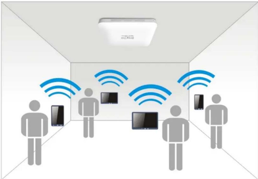
Interior view of a smart home with people standing and connected to multiple screens (no text or symbols visible)VigorAP 1000C can operate in standalone mode for your office network or a classroom; connected to your LAN and offering you wireless access.
It makes high density with quality-performance be feasible for users as it is going to be implemented with DrayTek VigorACS 2 supports configuration, firmware upgrade, status, and monitoring.
The Power of Ethernet (PoE) on VigorAP 1000C relieves the installation of the power plug. The massive deployment of VigorAP 1000CC for hospitalities and school environment will be much easier.
With the optimized antennas built-in, DrayTek VigorAP 1000C ceiling-mount wireless access point is ideal for hospitalities, small offices, and small campus.
Easy install procedures allows any computer users to setup a network environment in very short time - within minutes, even inexperienced users. Just follow the instructions given in this user manual, you can complete the setup procedure and release the power of this access point all by yourself!
I-1-1 LED Indicators and Connectors
Before you use the Vigor modem, please get acquainted with the LED indicators and connectors first.
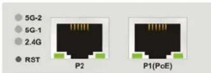
| LED Status Explanation | ||
| 5G-2 / 5G-1 / 2.4G | On Wireless function is ready. | |
| Off Wireless function is not ready. | ||
| Blinking Data is transmitting (sending/receiving). | ||
| P2 / P1(PoE)(Left LED) | On The LAN port is connected. | |
| Off LAN is disconnected. | ||
| Blinking Data is transmitting (sending/receiving). | ||
| P2 / P1(PoE)(Right LED) | On A normal connection (rate with 1000M) is through its corresponding port. | |
| Off The LAN port is connected with a transmission rate of 10/100Mbps if left LED is on. | ||
Note:
Connector P1(PoE) is used for PoE connection (for indoor use only).

natural_image
Front view of a network device showing ports P2 and P1(PoE) with a switch and port indicator (no text or symbols beyond labels)Interface Description
RST Restore the default settings.
Usage: Switch on the access point. Press and hold reset button for at least 5 seconds. VigorAP will restart with the factory default configuration.
P2/P1(PoE) Connectors for local networked devices.
USB

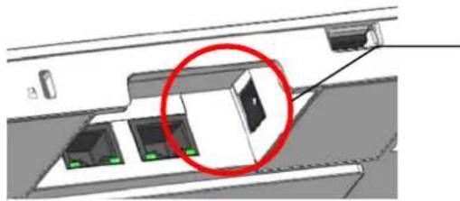
natural_image
Diagram of a device interior showing internal components with a red circle highlighting a specific area (no text or symbols present)The PWR connector (next to connector P1(PoE)) for a power adapter.
I-2 Hardware Installation
This section will guide you through installing the VigorAP.
Note:
For the sake of personal safety, only trained and qualified personnel should install this access point.
VigorAP can be mounted on the board of calcium silicate. Below shows an exploded view of VigorAP installation.
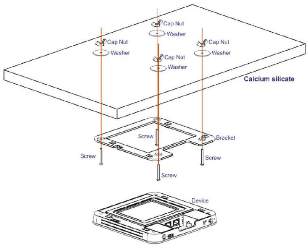
Follow the steps listed below to mount the access point.
- Place the bracket on the front side of the calcium silicate board and fasten it with four screws.
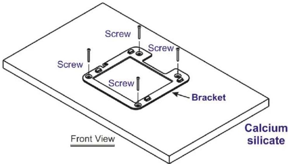
- When the bracket is in place, reverse the board. Put the washer on the screw.
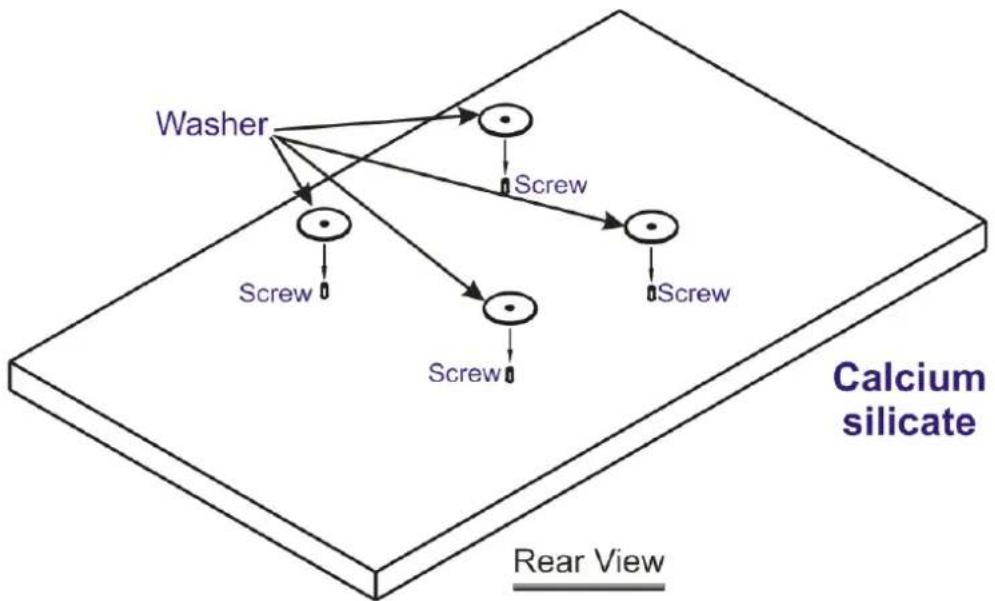
flowchart
graph TD
    Washer --> Screw1
    Washer --> Screw2
    Screw1 --> Screw3
    Screw2 --> Screw4
    Screw3 --> Screw5
    Screw4 --> Screw6
    Screw5 --> Screw7
    Screw6 --> Screw8
    Screw7 --> Screw9
    Screw8 --> Screw10
    Screw9 --> Screw11
    Screw10 --> Screw12
    Screw11 --> Screw13
    Screw12 --> Screw14
    Screw13 --> Screw15
    Screw14 --> Screw16
    Screw15 --> Screw17
    Screw16 --> Screw18
    Screw17 --> Screw19
    Screw18 --> Screw20
    Screw20 --> Screw21
    Screw21 --> Screw22
    Screw22 --> Screw23
    Screw23 --> Screw24
    Screw24 --> Screw25
    Screw25 --> Screw26
    Screw26 --> Screw27
    Screw27 --> Screw28
    Screw28 --> Screw29
    Screw29 --> Screw30
    Screw30 --> Screw31
    Screw31 --> Screw32
    Screw32 --> Screw33
    Screw33 --> Screw34
    Screw34 --> Screw35
    Screw35 --> Screw36
    Screw36 --> Screw37
    Screw37 --> Screw38
    Screw38 --> Screw39
    Screw39 --> Screw40
    Screw40 --> Screw41
    Screw41 --> Screw42
    Screw42 --> Screw43
    Screw43 --> Screw44
    Screw44 --> Screw45
    Screw45 --> Screw46
    Screw46 --> Screw47
    Screw47 --> Screw48
    Screw48 --> Screw49
    Screw49 --> Screw50
    Screw50 --> Screw51
    Screw51 --> Screw52
    Screw52 --> Screw53
    Screw53 --> Screw54
    Screw54 --> Screw55
    Screw55 --> Screw56
    Screw56 --> Screw57
    Screw57 --> Screw58
    Screw58 --> Screw59
    Screw59 --> Screw60
    Screw60 --> Screw61
    Screw61 --> Screw62
    Screw62 --> Screw63
    Screw63 --> Screw64
    Screw64 --> Screw65
    Screw65 --> Screw66
    Screw66 --> Screw67
    Screw67 --> Screw68
    Screw68 --> Screw69
    Screw69 --> Screw70
    Screw70 --> Screw71
    Screw71 --> Screw72
    Screw72 --> Screw73
    Screw73 --> Screw74
    Screw74 --> Screw75
    Screw75 --> Screw76
    Screw76 --> Screw77
    Screw77 --> Screw78
    Screw78 --> Screw79
    Screw79 --> Screw80
    Screw80 --> Screw81
    Screw81 --> Screw82
    Screw82 --> Screw83
    Screw83 --> Screw84
    Screw84 --> Screw85
    Screw85 --> Screw86
    Screw86 --> Screw87
    Screw87 --> Screw88
    Screw88 --> Screw89
    Screw89 --> Screw90
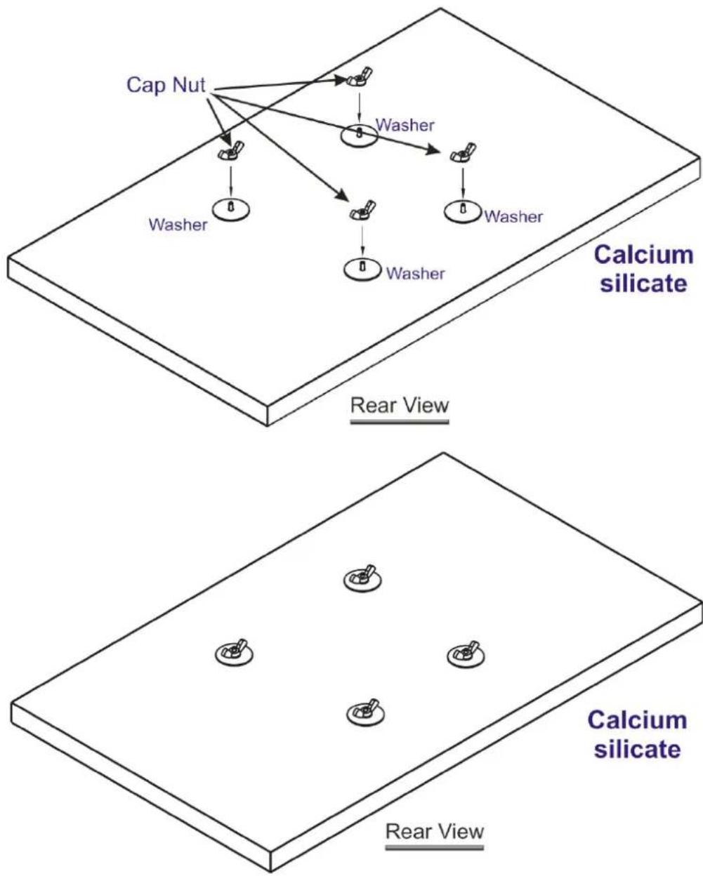
- Insert the cap nut to the screw on the washer. Rotate the cap nut until it locks firmly on the washer.
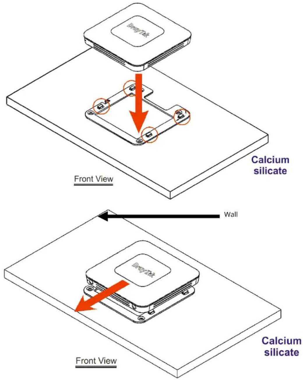
- There are four latches on the bracket. Put the device (VigorAP) on the bracket with the direction shown below.
I-3 Network IP Configuration
After the network connection is built, the next step you should do is setup VigorAP 1000C with proper network parameters, so it can work properly in your network environment.
Before you can connect to the access point and start configuration procedures, your computer must be able to get an IP address in the same subnet as this AP. If it's not connected to the same DHCP Server with the AP or you're unsure, please follow the following instructions to configure your computer to use the static IP address in the same subnet as default IP address of this AP.
For the default IP address of this AP is set "192.168.1.2", we recommend you to use "192.168.1.X (except 2)" in the field of IP address on this section for your computer.
If the operating system of your computer is...
Windows 10 - please go to section I-3-1
I-3-1 Windows 10 IP Address Setup
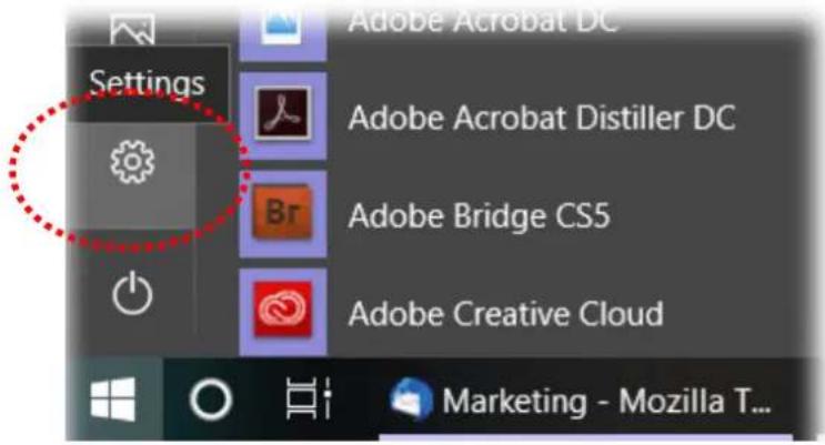
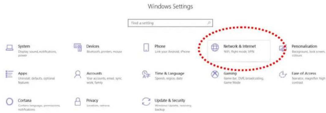
Click the Start button (it should be located at lower-left corner of your computer), then click the Settings icon.
Double-click Network & Internet.
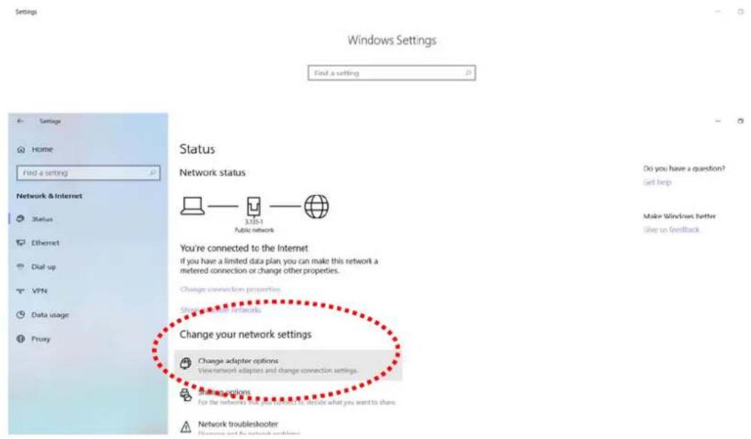
Next, click Change adapter options.
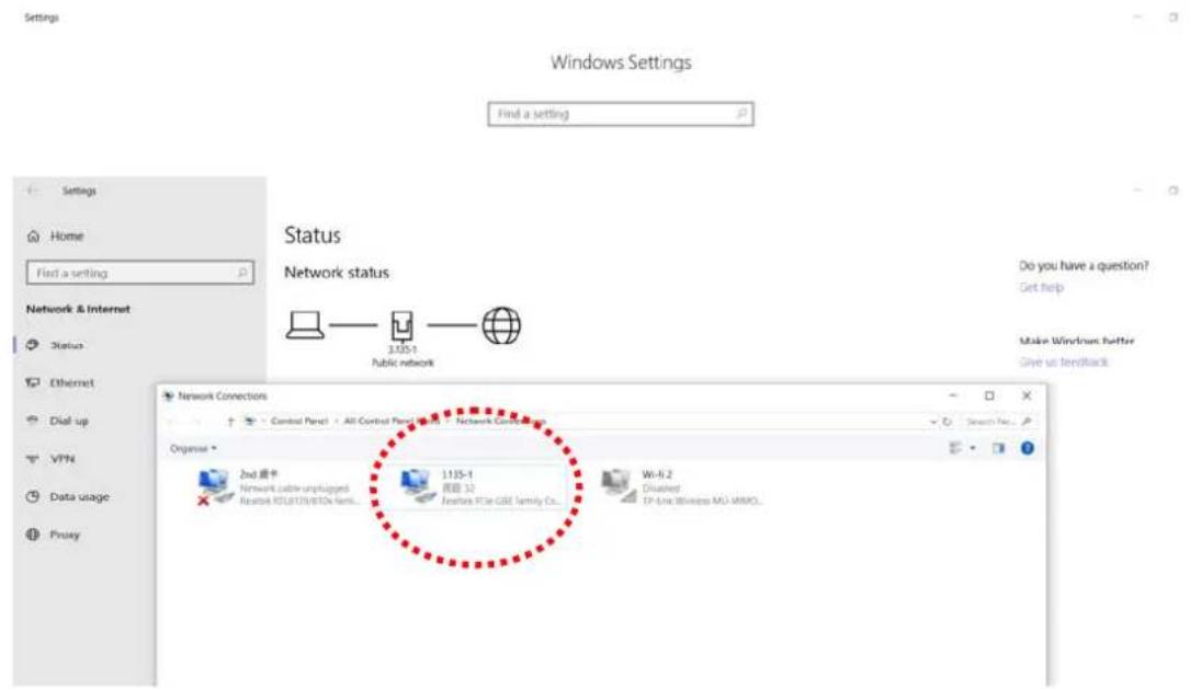
Click the local area connection.
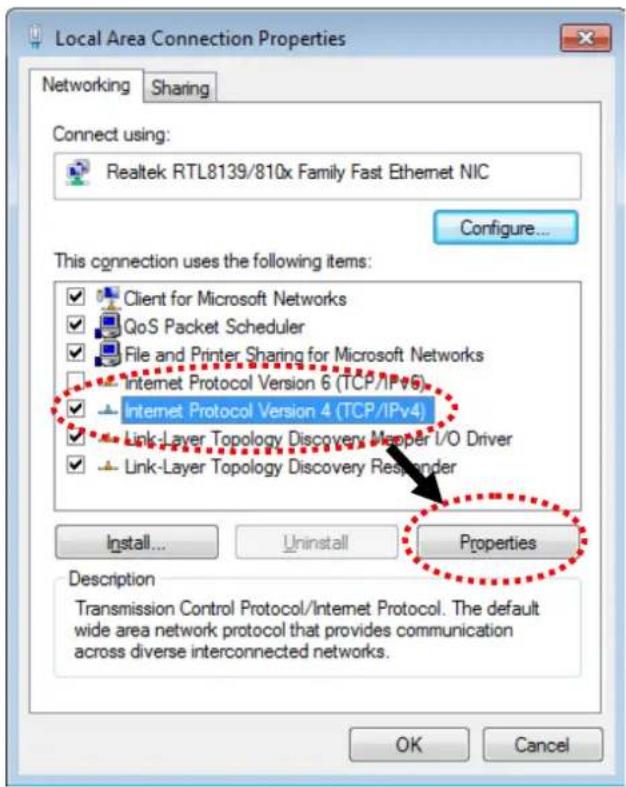
Then, select Internet Protocol Version 4 (TCP/IPv4) and click Properties.
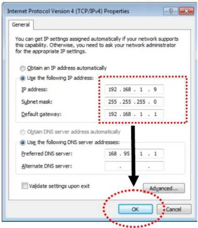
Under the General tab, click Use the following IP address. Then input the following settings in respective field and click OK when finish.
IP address: 192.168.1.9
Subnet Mask: 255.255.255.0
I-4 Accessing to Web User Interface
All functions and settings of this access point must be configured via web user interface. Please start your web browser (e.g., Firefox).
-
Make sure your PC connects to the VigorAP 1000C correctly.
-
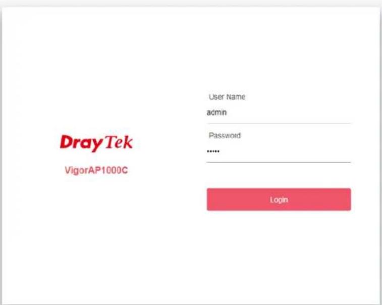
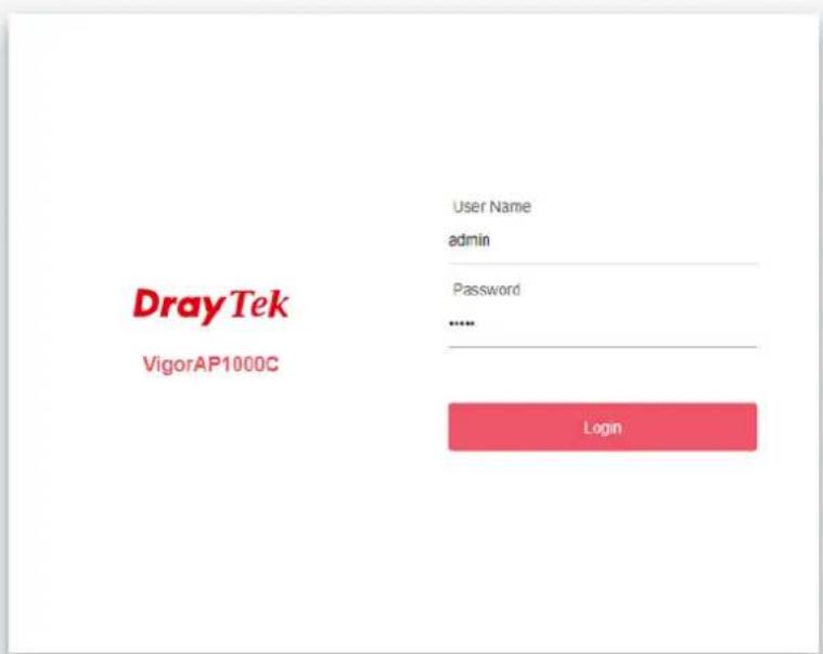
Open a web browser on your PC and type http://192.168.1.2. A pop-up window will open to ask for username and password. Pease type "admin/admin" on Username/Password and click OK.
Copyright © 2018 DrayTek Corp
i Note:
You may either simply set up your computer to get IP dynamically from the router or set up the IP address of the computer to be in the same subnet as the IP address of VigorAP 1000C.
- If there is no DHCP server on the network, then VigorAP 1000C will have an IP address of 192.168.1.2.
- If there is DHCP available on the network, then VigorAP 1000C will receive it's IP address via the DHCP server.
-
If you connect to VigorAP by wireless LAN, you could try to access the web user interface through http://vigorap.com.
-
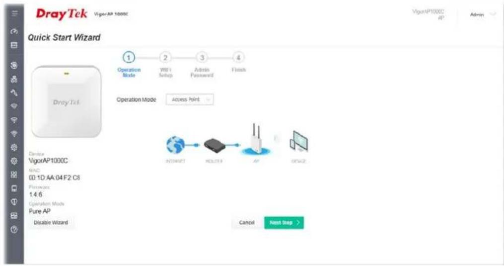
For the first time accessing VigorAP, the Quick Start Wizard for configuring wireless settings will appear as follows. Refer to Section I-7 Quick Start Wizard for detailed information.
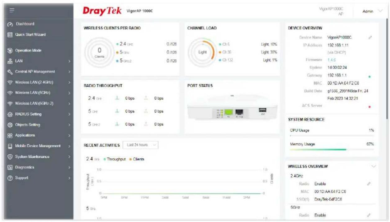
- If VigorAP has been configured previously, the Dashboard of VigorAP will appear as follows:
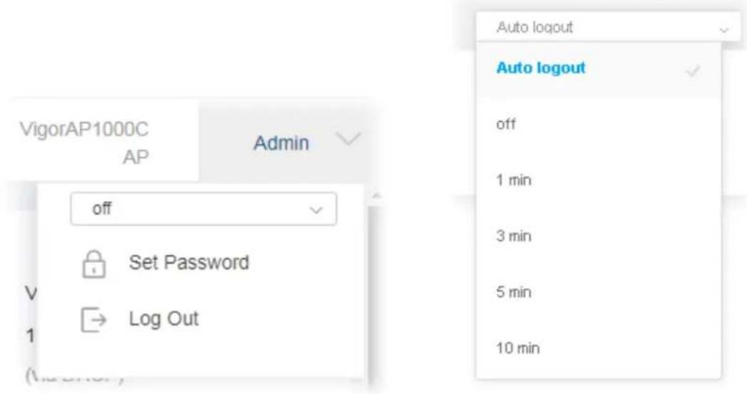
- The web page can be logged out by clicking Log Out on the top right of the web page. Or, logout the web user interface according to the chosen condition. The default setting is Auto Logout, which means the web configuration system will logout after 5 minutes without any operation. Change the setting of auto logout if you want.
Note:
If you fail to access the web configuration, please go to the section "Trouble Shooting" for detecting and solving your problem.
For using the device properly, it is necessary for you to change the password of web configuration for security and adjust primary basic settings.
I-5 Changing Password
-
Please change the password for the original security of the modem.
-
Go to System Maintenance page and choose Administration Password.
System Maintenance >> Administration Password
Administrator Settings
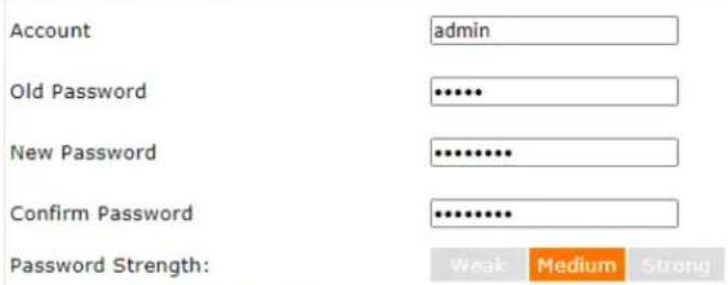
Strong password requirements:
-
Have at least one upper-case letter and one lower-case letter.
-
Including non-alphanumeric characters is a plus.
Note : Authorization Account can contain only a-z A-Z 0-9, \~ ! @ \$ % ^ * () _ - + = {} [] | ; < > .
Authorization Password can contain only a-z A-Z 0-9, \~ ! @ # \$ % ^ & = () _ - + = {} [] | \; < > . ? /
OK
Cancel
- Enter the new login password on the field of Password. Then click OK to continue.
- Now, the password has been changed. Next time, use the new password to access the Web User Interface for this modem.
Copyright © 2018 DrayTek Corp
I-6 Dashboard
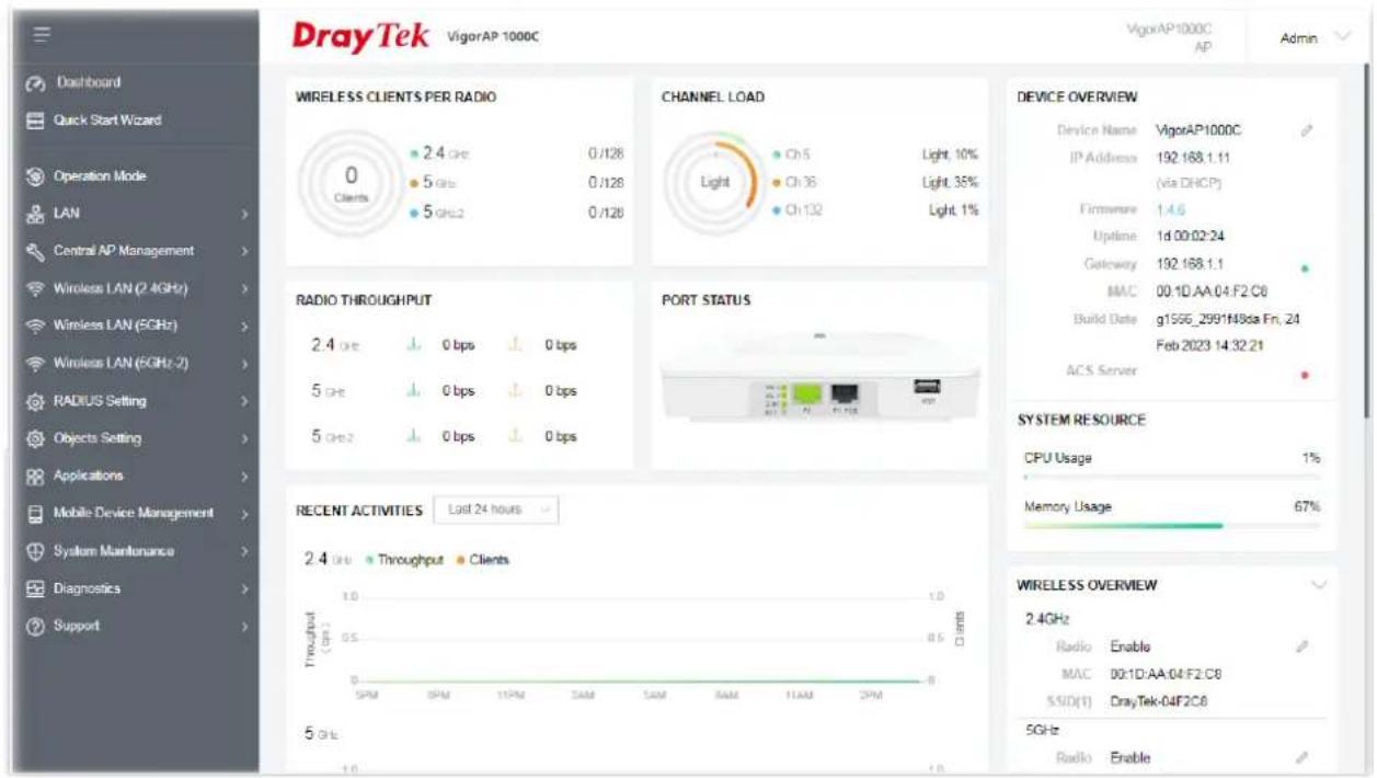
Dashboard shows system status including the number of client connected, throughput, gateway, physical connection status, radio (2.4GHz / 5GHz / 5GHz-2) status, backhaul network, recent activities, wireless network usage, and so on.
Click Dashboard from the main menu on the left side of the main page.
I-7 Quick Start Wizard
Quick Start Wizard will guide you to configure 2.4G /5G/5G-2 wireless setting and other corresponding settings for Vigor Access Point step by step.
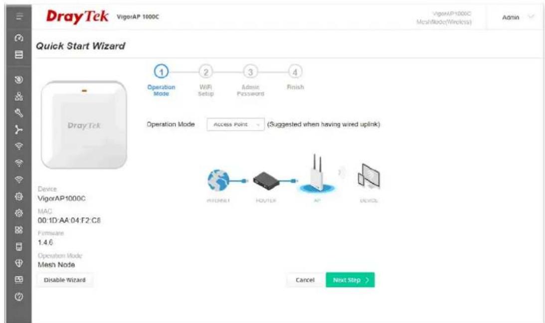
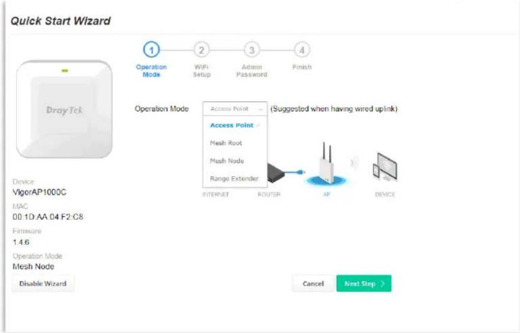
Available operation mode includes:
- Access Point
- Mesh Root
- Mesh Node
- Range Extender
In this page, the advanced settings pages will vary according to the operation mode specified.
I-7-1 Settings for Access Point
- Choose Access Point as the operation mode and click Next Step.
- In the following page, configure the settings for wireless LAN (for 2.4GHz, 5GHz and 5GHz-2) and click Next Step.
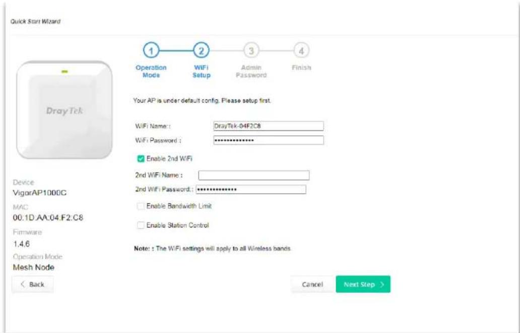
Available settings are explained as follows:
| Item | Description |
| WiFi Name Set a name for VigorAP 1000C to be identified. | |
| WiFi Password | Type 8~63 ASCII characters, such as 012345678..(or 64 Hexadecimal digits leading by 0x, such as "0x321253abcde..."). |
| Enable 2nd Wireless | Check the box to enable theguestwireless setting.Such feature is especially useful for free Wi-Fi service. For example, a coffee shop offers free Wi-Fi service for its guests for one hour every day.2nd WiFi Name- Set a name for VigorAP device which can be identified and connected by wireless guest.2nd WiFi Password- Set 8~63 ASCII characters or64 Hexadecimal digits leading by 0x which can be used for logging into VigorAP device by wireless guest. |
| Enable Bandwidth Limit | Check the box to define the maximum speed of the data uploading/downloading which will be used for the guest connecting to Vigor device with the same SSID.Upload Limit- Scroll the radio button to choose the value you want.Download Limit-Scroll the radio button to choose the value you want. |
| Enable Station Control | Check the box to set the duration for the guest connecting /reconnecting to Vigor device.Connection Time-Scroll the radio button to choose the value you want.Reconnection Time-Scroll the radio button to choose the value you want. |
- Change the default password for such device with new value. Then click Next Step.
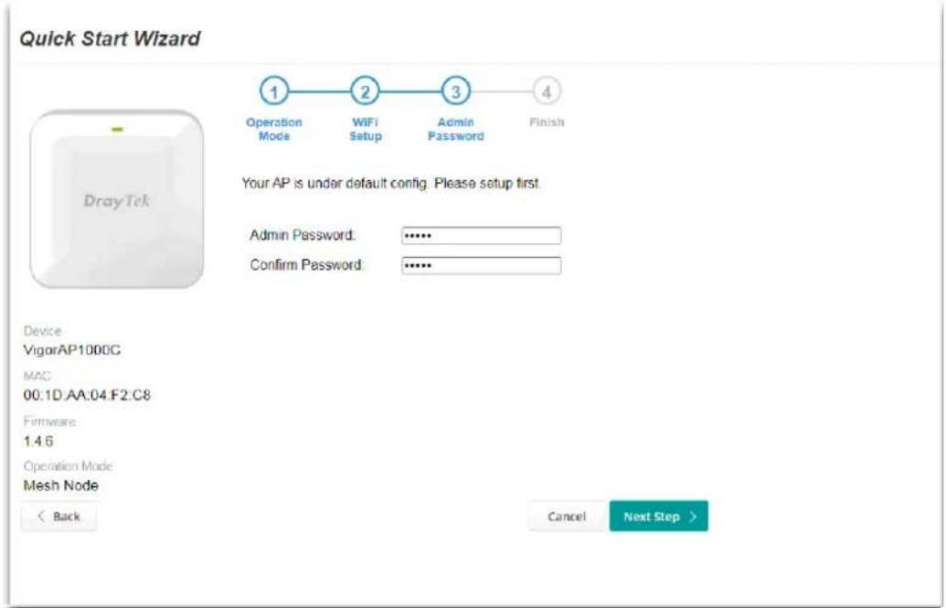
Available settings are explained as follows:
| Item | Description |
| Admin Password | Enter a new password. |
| ConfirmPassword | Enter the new password again for confirmation. |
- A summary of settings configuration will be shown on screen. Click Finish.
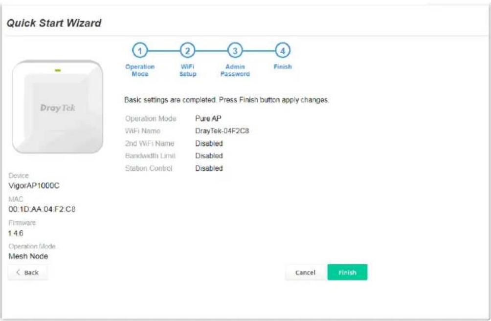
I-7-2 Settings for Mesh Root
- Choose Mesh Root as the operation mode and click Next Step.
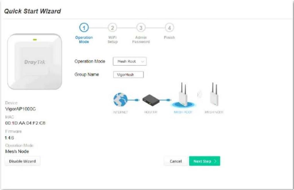
- Configure the settings for wireless LAN (for 2.4GHz, 5GHz and 5GHz-2) and click Next Step.
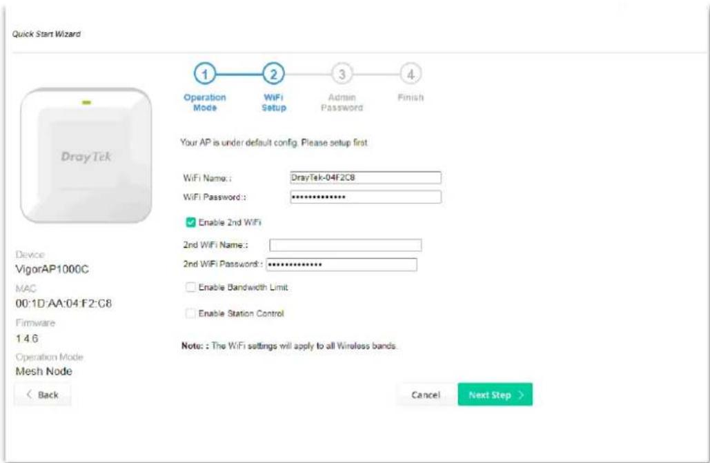
Available settings are explained as follows:
| Item | Description |
| WiFi Name Set a name for VigorAP 1000C to be identified. | |
| WiFi Password | Type 8~63 ASCII characters, such as 012345678..(or 64 Hexadecimal digits leading by 0x, such as "0x321253abcde..."). |
| Enable 2nd WiFi | Check the box to enable the second wireless setting. Such feature is especially useful for free Wi-Fi service. For example, a coffee shop offers free Wi-Fi service for its guests for one hour every day. 2nd WiFi Name - Set a name for VigorAP 1000C which can be identified and connected by wireless guest. 2nd WiFi Password - Set 8~63 ASCII characters or 64 Hexadecimal digits leading by 0x which can be used for logging into VigorAP 1000C by wireless guest. |
| Enable Bandwidth Limit | Check the box to define the maximum speed of the data uploading/downloading which will be used for the guest connecting to Vigor device with the same SSID. Upload Limit - Scroll the radio button to choose the value you want. Download Limit -Scroll the radio button to choose the value you want. |
| Enable Station Control | Check the box to set the duration for the guest connecting /reconnecting to Vigor device. Connection Time -Scroll the radio button to choose the value you want. Reconnection Time -Scroll the radio button to choose the value you want. |
- Change the default password for such device with new value. Then click Next Step.
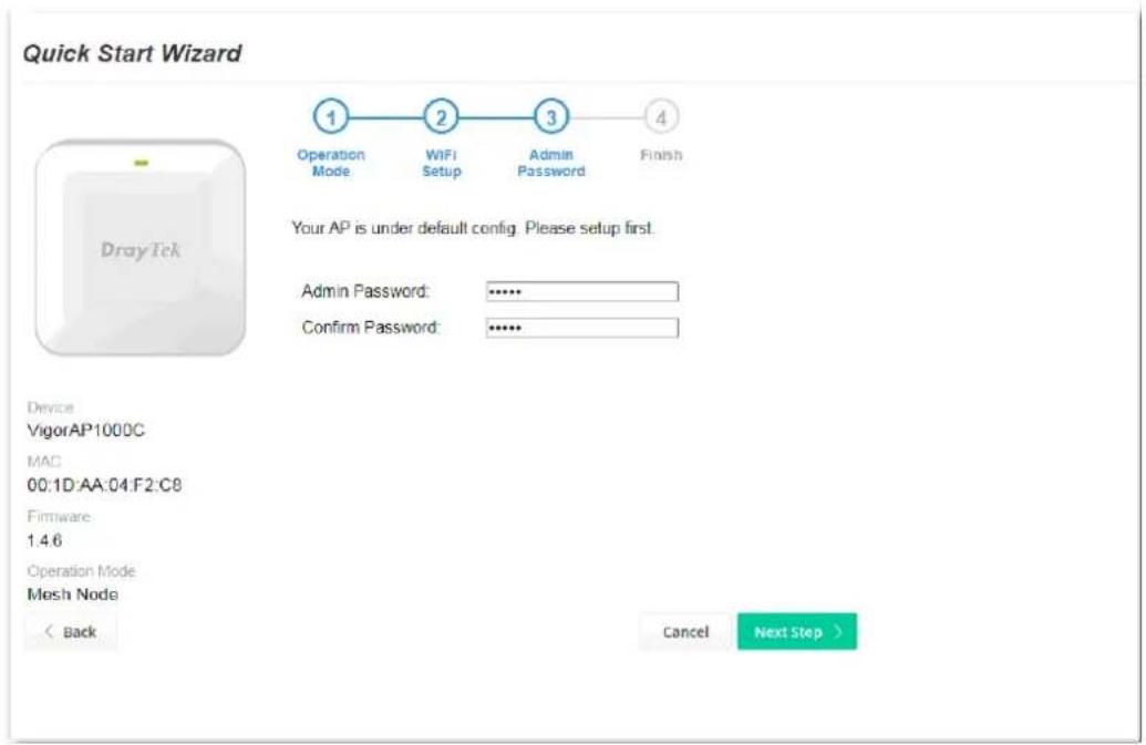
Available settings are explained as follows:
| Item | Description |
| Admin Password | Enter a new password. |
| ConfirmPassword | Enter the new password again for confirmation. |
- A summary of settings configuration will be shown on screen. Click Finish.
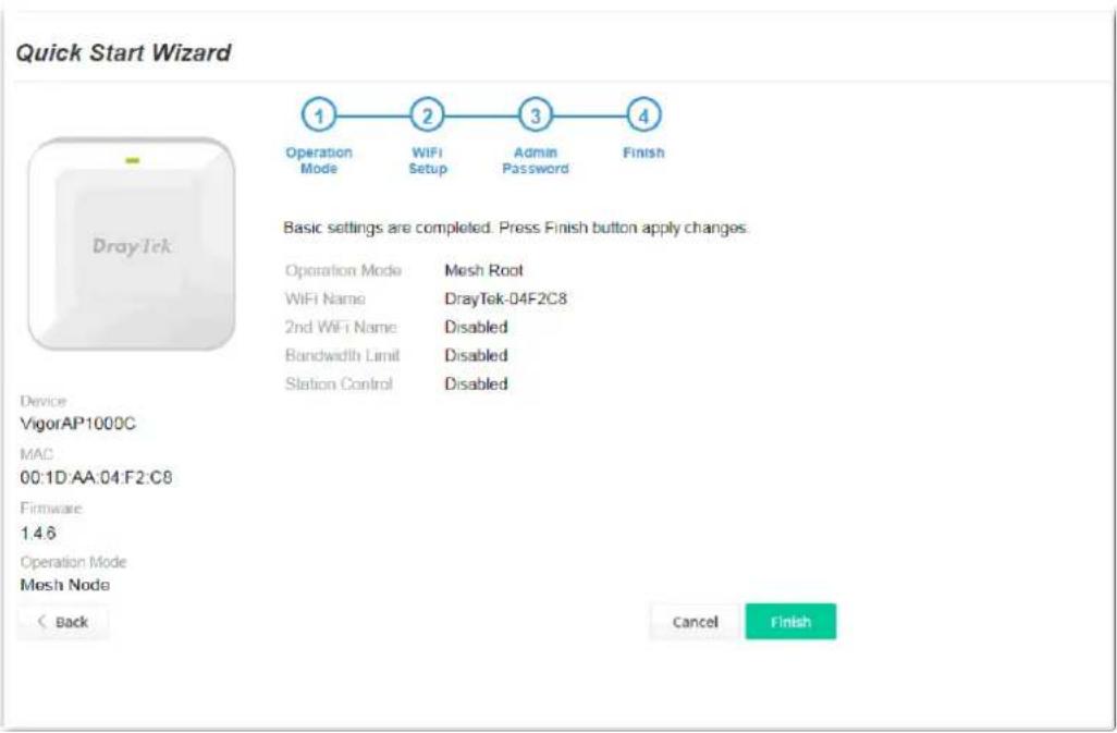
- After clicking Finish, the following web page appears. VigorAP will search for mesh node around the network.
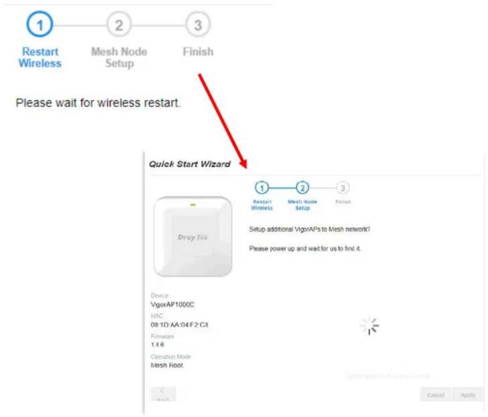
flowchart
graph TD
    A["1"] --> B["2"] --> C["3"]
    D["Restart Wireless"] --> E["Mesh Node Setup"] --> F["Finish"]
    G["Please wait for wireless restart."] --> H["Quick Start Wizard"]
    I["1"] --> J["2"] --> K["3"]
    L["Setup additional VigorAPs to Mesh network?"] --> M["Device: VigorAP1000C MAC 08:1D-AA:04:F2:C8 Firmware 1.4.6 Operation Mode Mesh Root"]
- Available VigorAP devices will be shown on the screen. Select the device (as a mesh node) for grouping under such mesh group and enter a device name for identification.
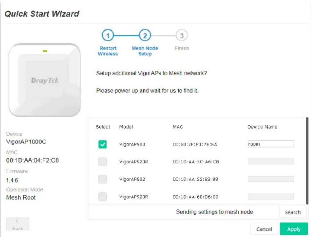
- Click Apply and wait for a while.
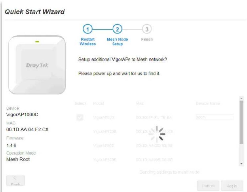
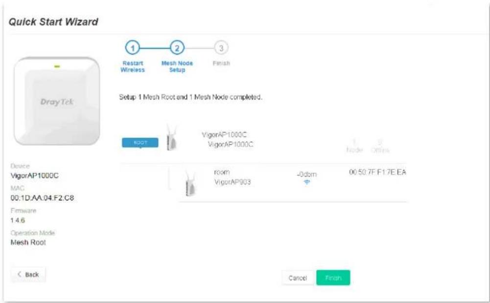
- Later, a summary page of mesh root with mesh node will be shown on the screen.
I-7-3 Settings for Mesh Node
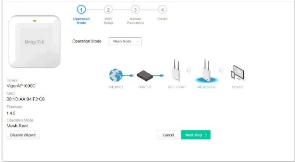
- Choose Mesh Node as the operation mode and click Next Step.
Quick Start Wizard
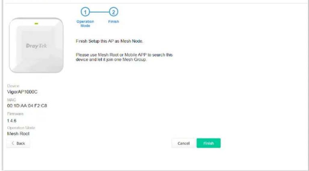
- A summary of settings configuration will be shown on screen. Click Finish.
Quick Start Wizard
I-7-4 Settings for Range Extender
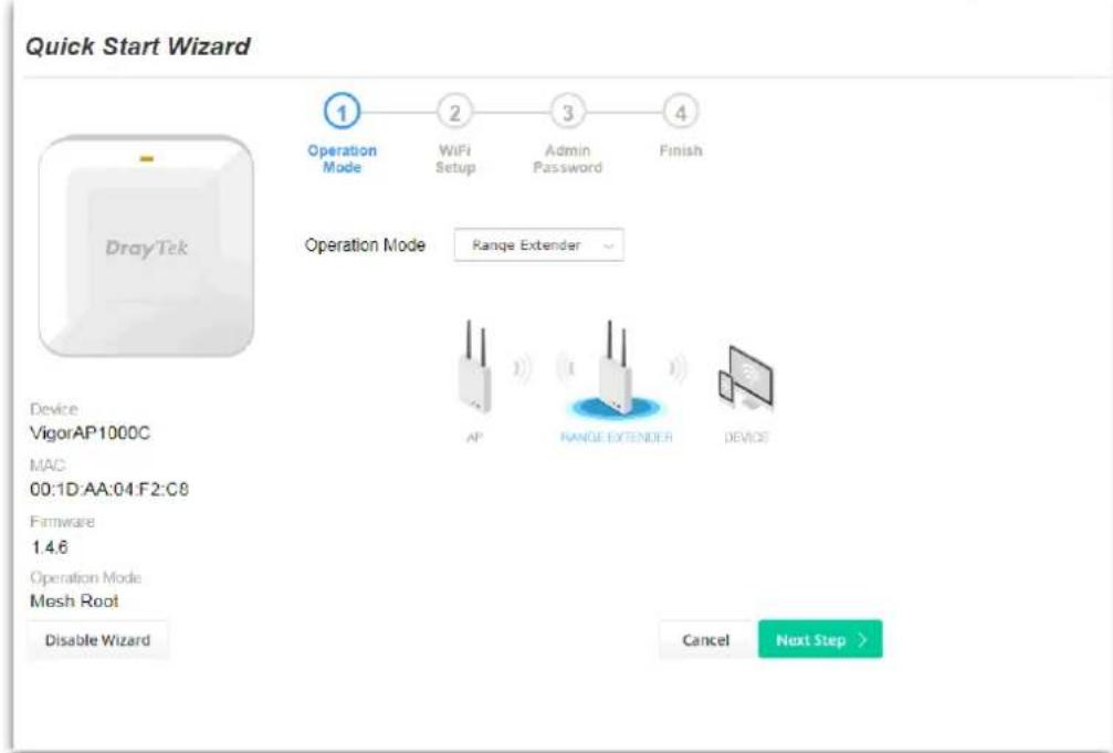
- Choose Range Extender as the operation mode and click Next Step.
- Configure the settings for wireless LAN (for 2.4GHz, 5GHz and 5GHz-2) and click Next Step.
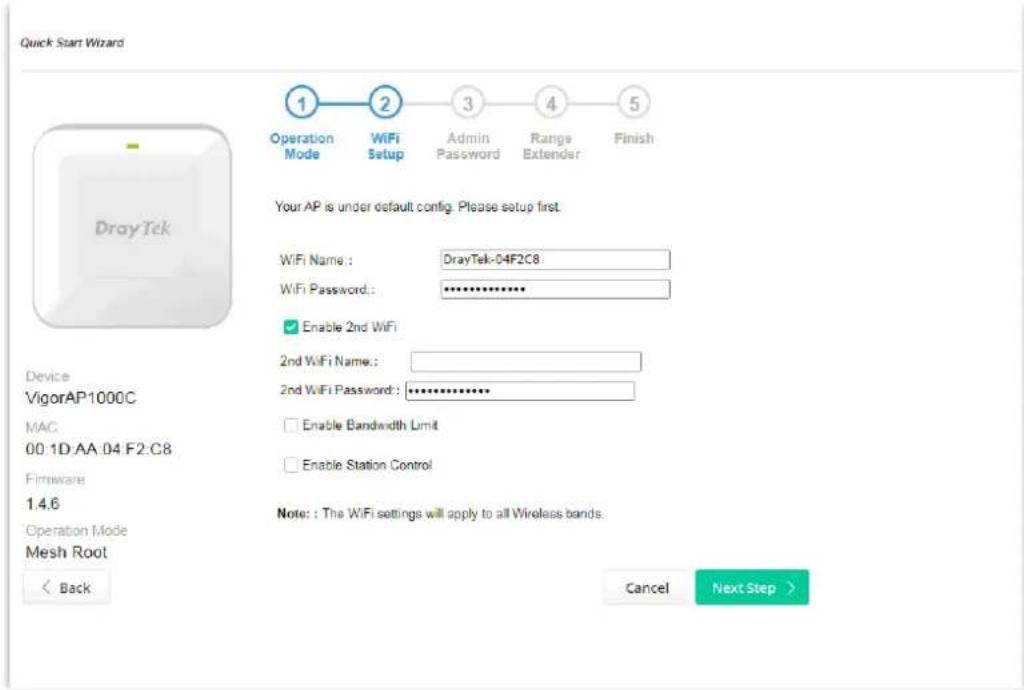
Available settings are explained as follows:
| Item | Description |
| WiFi Name Set a name for VigorAP 1000C to be identified. | |
| WiFi Password | Type 8~63 ASCII characters, such as 012345678..(or 64 Hexadecimaldigits leading by 0x, such as "0x321253abcde..."). |
| Enable 2nd WiFi | Check the box to enable the second wireless setting.Such feature is especially useful for free Wi-Fi service. For example, a coffee shop offers free Wi-Fi service for its guests for one hour every day.2nd WiFi Name- Set a name for VigorAP 1000C which can be identified and connected by wireless guest.2nd WiFi Password- Set 8~63 ASCII characters or 64 Hexadecimal digits leading by 0x which can be used for logging into VigorAP 1000C by wireless guest. |
| Enable Bandwidth Limit | Check the box to define the maximum speed of the data uploading/downloading which will be used for the guest connecting to Vigor device with the same SSID.Upload Limit- Scroll the radio button to choose the value you want.Download Limit-Scroll the radio button to choose the value you want. |
| Enable Station Control | Check the box to set the duration for the guest connecting /reconnecting to Vigor device.Connection Time-Scroll the radio button to choose the value you want.Reconnection Time-Scroll the radio button to choose the value you want. |
- Change the default password for such device with new value. Then click Next Step.
Quick Start Wizard
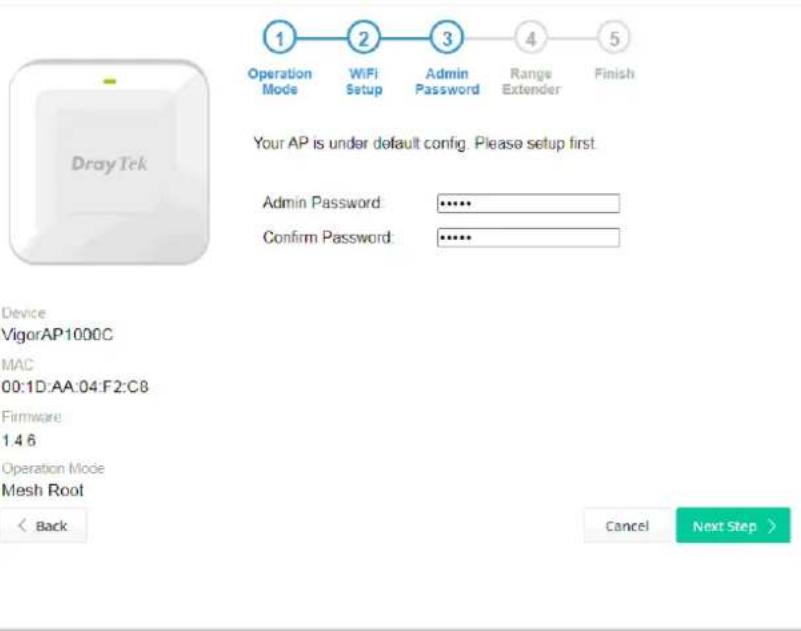
Available settings are explained as follows:
| Item | Description |
| Admin Password | Enter a new password. |
| ConfirmPassword | Enter the new password again for confirmation. |
- In the following page, click Search to find out neighboring access point. When all the available access points appear on the page, click the one you want to connect. Corresponding settings (e.g., SSID, Security Mode) of the selected device will be shown below. Enter the Security Key. Then click Next Step.
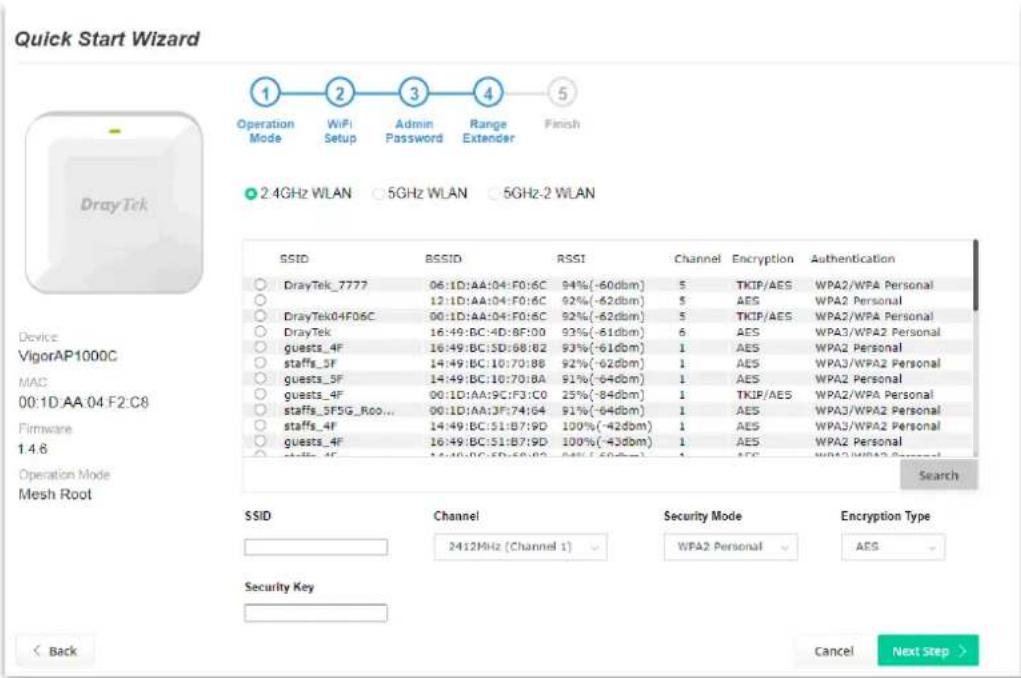
Available settings are explained as follows:
| Item | Description |
| SSID Displays the SSID of the selected access point. | |
| Channel | Means the channel frequency of the wireless LAN. You may switch channel if the selected channel is under serious interference. |
| Security Mode There are several modes provided for you to choose. Each mode will bring up different parameters (e.g., WEP keys, Pass Phrase) for you to configure. | |
| Encryption Type | Available options will vary according to the selected Security Mode.When Open is selected:Choose None to disable the WEP Encryption. Data sent to the AP will not be encrypted.WEP Keys-To enable WEP encryption for data transmission, please choose WEP. Four keys can be entered here, but only one key can be selected at a time. The format of WEP Key is restricted to 5 ASCII characters or 10 hexadecimal values in 64-bit encryption level, or restricted to 13 ASCII characters or 26 hexadecimal values in 128-bit encryption level. The allowed content is the ASCII characters from 33(!) to 126(~) except '#' and ''.When Shared is selected:WEP Keys- To enable WEP encryption for data transmission, please choose WEP. Four keys can be entered here, but only one key can be selected at a time. The format of WEP Key is restricted |
to 5 ASCII characters or 10 hexadecimal values in 64-bit encryption level, or restricted to 13 ASCII characters or 26 hexadecimal values in 128-bit encryption level. The allowed content is the ASCII characters from 33(!) to 126(\~) except '#' and
When WPA/PSK or WPA2/PSK is selected:
- Select TKIP or AES as the algorithm for WPA.
Security Key - Enter 8\~63 ASCII characters, such as 012345678..(or 64 Hexadecimal digits leading by 0x, such as "0x321253abcde...").
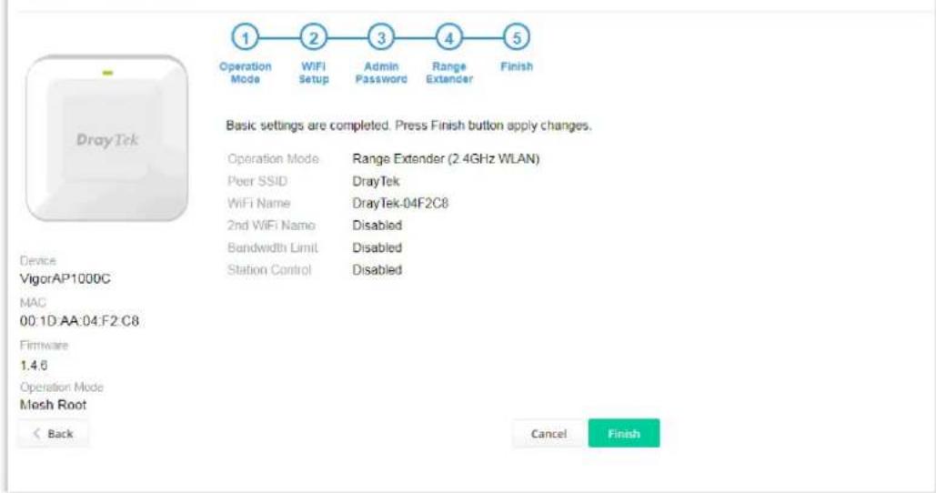
- A summary of settings configuration will be shown on screen. Click Finish.
Quick Start Wizard
This page is left blank.
Chapter II Connectivity

natural_image
Abstract geometric composition with four gray squares and one red diamond (no text or symbols)This page provides several available modes for you to choose for different conditions. Click any one of them and click OK. The system will configure the required settings automatically.
Operation Mode Configuration
AP:
VigorAP acts as a bridge between wireless devices and wired Ethernet network, and exchanges data between them.
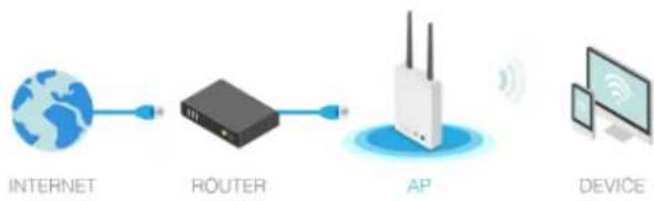
flowchart
graph LR
    A["INTERNET"] --> B["ROUTER"]
    B --> C["AP"]
    C --> D["DEVICE"]
Mesh :
Mesh Root:
AP connects to gateway with Ethernet cable. It would be other AP's uplink connection.
Mesh Node:
Use wireless to connect to other Mesh Root when Ethernet cable doesn't exist. A mesh network creates a set of links automatically and calculate the most optimal wireless path through the wireless network back to a wired Mesh Root.
Range Extender :
VigorAP can act as a wireless repeater; it can be Station and AP at the same time.
OK
Available settings are explained as follows:
| Item | Description |
| AP | This mode allows wireless clients to connect to access point and exchange data with the devices connected to the wired network. |
| Mesh Mesh Root - VigorAP must connect to a gateway with an Ethernet cable. | Mesh Node - VigorAP can connect to other mesh root via wireless connection. A mesh network creates one set of links automatically and calculates the most optimal wireless path through the wireless network back to a wired mesh root. |
| Range Extender VigorAP can act as a wireless repeater which will help you to extend the networking wirelessly. The access point can act as Station and AP at the same time. It can use Station function to connect to a Root AP and use AP function to service all wireless clients within its coverage. | |
Note:
The Wireless LAN settings will be changed according to the Operation Mode selected here. For the detailed information, please refer to the section of Wireless LAN.
II-2 General Concepts for Wireless LAN
VigorAP 1000C is a highly integrated wireless local area network (WLAN) for 5 GHz 802.11ac or 2.4/5 GHz 802.11n WLAN applications. It supports channel operations of 20/40 MHz at 2.4 GHz and 20/40/80 MHz at 5 GHz. VigorAP 1000C can support data rates up to 867 MBps in 802.11ac 80 MHz channels.
Note:
* The actual data throughput will vary according to the network conditions and environmental factors, including volume of network traffic, network overhead and building materials.
VigorAP 1000C plays a role as an Access Point (AP) connecting to lots of wireless clients or Stations (STA). All the STAs will share the same Internet connection via VigorAP 1000C. The General Setup will set up the information of this wireless network, including its SSID as identification, located channel etc.
Security Overview
WEP (Wired Equivalent Privacy) is a legacy method to encrypt each frame transmitted via radio using either a 64-bit or 128-bit key. Usually access point will preset a set of four keys and it will communicate with each station using only one out of the four keys.
WPA (Wi-Fi Protected Access), the most dominating security mechanism in industry, is separated into two categories: WPA-personal or called WPA Pre-Share Key (WPA/PSK), and WPA-Enterprise or called WPA/802.1x.
In WPA-Personal, a pre-defined key is used for encryption during data transmission. WPA applies Temporal Key Integrity Protocol (TKIP) for data encryption while WPA2 applies AES. The WPA-Enterprise combines not only encryption but also authentication.
Since WEP has been proved vulnerable, you may consider using WPA for the most secure connection. You should select the appropriate security mechanism according to your needs. No matter which security suite you select, they all will enhance the over-the-air data protection and/or privacy on your wireless network. The VigorAP 1000C is very flexible and can support multiple secure connections with both WEP and WPA at the same time.
WPS Introduction
WPS (Wi-Fi Protected Setup) provides easy procedure to make network connection between wireless station and wireless access point (VigorAP 1000C) with the encryption of WPA and WPA2.
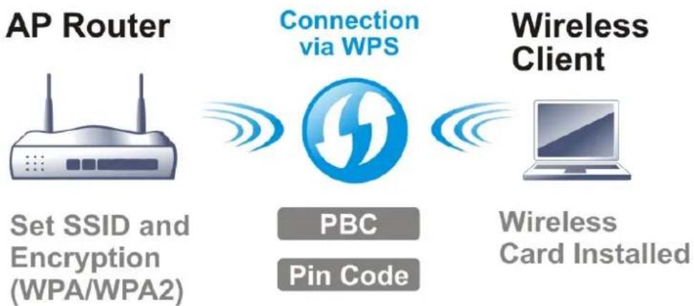
flowchart
graph LR
    A["AP Router"] -->|Set SSID and Encryption (WPA/WPA2)| B["Connection via WPS"]
    B -->|PBC Pin Code| C["Wireless Client"]
    C -->|Wireless Card Installed| D["Computer"]
It is the simplest way to build connection between wireless network clients and VigorAP 1000C. Users do not need to select any encryption mode and type any long encryption passphrase to setup a wireless client every time. He/she only needs to press a button on wireless client, and WPS will connect for client and VigorAP 1000C automatically.
Note:
Such function is available for the wireless station with WPS supported.
There are two methods to do network connection through WPS between AP and Stations: pressing the Start PBC button or using PIN Code.
On the side of VigorAP 1000C series which served as an AP, press WPS button once on the front panel of VigorAP 1000C or click Start PBC on web configuration interface. On the side of a station with network card installed, press Start PBC button of network card.
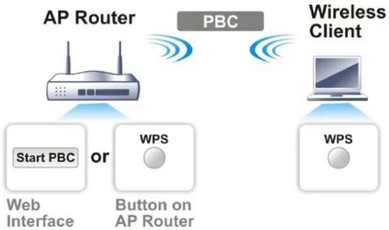
flowchart
graph TD
    A["AP Router"] -->|Start PBC or| B["Web Interface"]
    A -->|Start PBC or| C["Button on AP Router"]
    D["Wireless Client"] -->|WPS| E["WPS"]
    D -->|WPS| F["Computer"]
    style A fill:#f9f,stroke:#333
    style D fill:#ccf,stroke:#333
    style B fill:#dfd,stroke:#333
    style C fill:#dfd,stroke:#333
    style E fill:#dfd,stroke:#333
    style F fill:#dfd,stroke:#333
If you want to use PIN code, you have to know the PIN code specified in wireless client. Then provide the PIN code of the wireless client you wish to connect to the VigorAP 1000C.
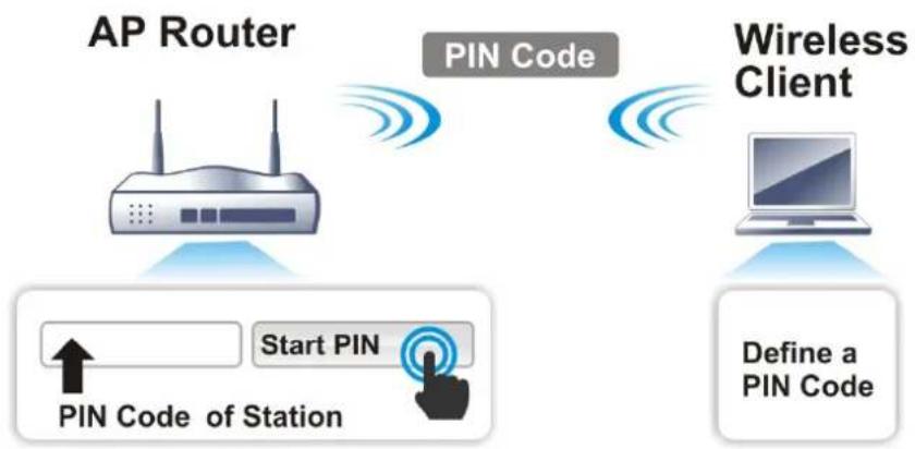
flowchart
graph TD
    A["AP Router"] -->|PIN Code| B["Wireless Client"]
    B -->|Define a PIN Code| C["Application Pin Code of Station"]
    A -->|Start PIN| D["User Input"]
Web Interface
II-3 Wireless LAN (2.4GHz/5GHz/5GHz-2) Settings for AP Mode
VigorAP 1000C is a tri-band, including 2.4GHz/5GHz/5GHz-2, access point. In which, the band of 5GHz-2 can deliver double bandwidths over 5GHz to offer more stable wireless performance.
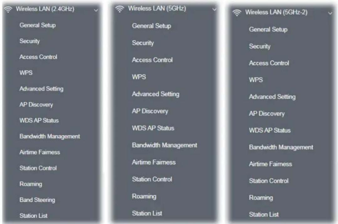
When you choose AP as the operation mode, the Wireless LAN menu items will include General Setup, Security, Access Control, WPS, Advanced Setting, AP Discovery, WDS AP Status, Bandwidth Management, Airtime Fairness, Station Control, Roaming, Band Steering (for 2.4GHz) and Station List.
Note:
Available settings for Wireless LAN (2.4GHz), Wireless LAN (5GHz) and Wireless LAN (5GHz-2) are almost the same, except for Band Steering.
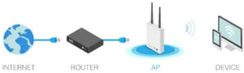
The following figure shows how VigorAP runs as AP (Access Point)
flowchart
graph LR
    A["INTERNET"] --> B["ROUTER"]
    B --> C["AP"]
    C --> D["DEVICE"]
II-3-1 General Setup
By clicking the General Setup, a new web page will appear so that you could select mode, channel, the SSID, the wireless channel, 2nd subnet and WDS. Please refer to the following figure for more information.
Wireless LAN (2.4GHz) >> General Setup
General Setting ( IEEE 802.11 )
Enable Wireless LAN

Mode : Mixed(11b+11g+11n)
Channel : 2462MHz (Channel 11)
Extension Channel : 2442MHz (Channel 7)
Enable 2 Subnet (Simulate 2 APs)
Enable Bridge VLAN to Mesh
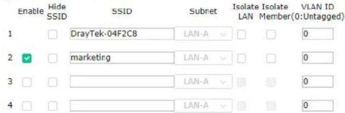
Hide SSID: Prevent SSID from being scanned. Isolate LAN: Wireless clients (stations) with the same SSID cannot access wired PCs on LAN. Isolate Member: Wireless clients (stations) with the same SSID cannot access for each other. Isolate Exception: Isolate Exception can be created by adding the MAC from Device Object.
WDS Settings (PHY Mode : HTMIX)
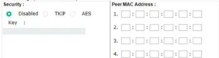
Note: Enter the configuration of APs which AP1000C want to connect. Remote AP should always use LAN-A or SSID1 MAC address to connect AP1000C WDS.
OK
Cancel
Available settings are explained as follows:
| Item | Description |
| Enable Wireless LAN Check the box to enable wireless function. | |
| Enable Client Limit | Check the box to set the maximum number of wireless stations which try to connect Internet through Vigor device. The number you can set is from 3 to 64. |
| Enable Client Limit per | Define the maximum number of wireless stations per SSID which try to connect to Internet through Vigor device. The number you can set |
| SSID is from 3 to 64. | |
| Mode At present, VigorAP | 1000C can connect to 11a only, 11n only, Mixed(11a+11n), and Mixed (11a+11n+11ac) stations simultaneously. Simply choose Mixed (11a+11n+11ac) mode. |
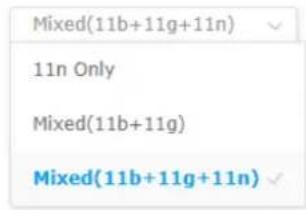 (for 2.4GHz) (for 2.4GHz) | |
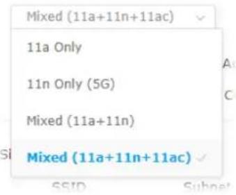 (for 5GHz / 5GHz-2) (for 5GHz / 5GHz-2) | |
| Channel Means the channel of frequency of the wireless LAN. | |
| Extension Channel(for 2.4GHz) | With 802.11n, there is one option to double the bandwidth per channel. The available extension channel options will be varied according to the Channel selected above. Configure the extension channel you want. |
| Enable 2 Subnet(Simulate 2 APs) | Check the box to enable the function for two independent subnets.Once you enable this function, LAN-A and LAN-B would be independent. Next, you can connect one router in LAN-A, and another router in LAN-B. Such mechanism can make you feeling that you have two independent AP/subnet functions in one VigorAP 1000C.If you disable this function, LAN-A and LAN-B ports are in the same domain. You could only connect one router (no matter connecting to LAN-A or LAN-B) in this environment. |
| Enable Check it to enable the SSID setting. | |
| Hide SSID | Check it to prevent from wireless sniffing and make it harder for unauthorized clients or STAs to join your wireless LAN. Depending on the wireless utility, the user may only see the information except SSID or just cannot see any thing about VigorAP 1000C while site surveying. The system allows you to set four sets of SSID for different usage. |
| SSID Set a name for VigorAP 1000C to be identified. Default settings are | |
| DrayTek-LAN-A and DrayTek-LAN-B. When Enable 2 Subnet is enabled, you can specify subnet interface (LAN-A or LAN-B) for each SSID by using the drop down menu. | |
| Subnet Choose LAN-A or | LAN-B for each SSID. If you choose LAN-A, the wireless clients connecting to this SSID could only communicate with LAN-A. |
| Isolate LAN Check this box to isolate the wireless connection from LAN. It can make the wireless clients (stations) with remote-dial and LAN to LAN users not accessing for each other. | |
| Isolate Member | Check this box to make the wireless clients (stations) with the same SSID not access for each other. |
| VLAN ID Type the value for such SSID. Packets transferred from such SSID to LAN will be tagged with the number. | |
| PHY Mode Data will be transmitted via HTMIX mode. | |
| Security | Select WEP, TKIP or AES as the encryption algorithm. |
| Type 8~63 ASCII characters, such as 012345678..(or 64 Hexadecimal digits leading by 0x, such as "0x321253abcde..."). | |
| Peer MAC Address | Type the peer MAC address for the access point that VigorAP connects to. |
After finishing this web page configuration, please click OK to save the settings.
II-3-2 Security
This page allows you to set security with different modes for SSID 1, 2, 3 and 4 respectively. After configuring the correct settings, please click OK to save and invoke it.
By clicking the Security Settings, a new web page will appear so that you could configure the settings.
Wireless LAN (2.4GHz) >> Security Settings
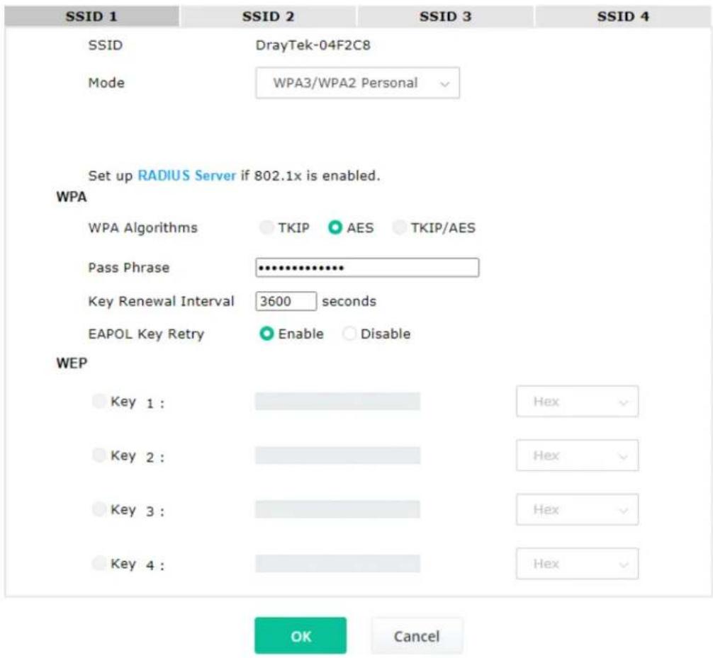
Available settings are explained as follows:
| Item | Description |
| Mode | There are several modes provided for you to choose.Below shows the modes with higher security;WPA3 Personal, WPA3/WPA2 Personal, WPA2 Personal, WPA2/WPA Personal - Accepts only WPA clients and the encryption key should be entered in PSK. The WPA encrypts each frame transmitted from the radio using the key, which either PSK (Pre-Shared Key) entered manually in this field below or automatically negotiated via 802.1x authentication.The WPA encrypts each frame transmitted from the radio using the key, which either PSK (Pre-Shared Key) entered manually in this field below or automatically negotiated via 802.1x authentication. Select WPA, WPA2 or Auto as WPA mode. |
| WPA3/WPA2 PersonalWPA3 PersonalWPA3/WPA2 PersonalWPA2 PersonalWPA2/WPA PersonalWPA3 EnterpriseWPA3/WPA2 EnterpriseWPA2 EnterpriseWPA2/WPA EnterpriseOWE----Not Secure----WPA PersonalWPA EnterpriseWEP PersonalWEP EnterpriseNone | WPA3 Enterprise, WPA3/WPA2 Enterprise, WPA2 Enterprise,WPA2/WPA Enterprise - The WPA encrypts each frame transmitted from the radio using the key, which either PSK (Pre-Shared Key) entered manually in this field below or automatically negotiated via 802.1x authentication.WPA2 Enterprise - The WPA encrypts each frame transmitted from the radio using the key, which either PSK (Pre-Shared Key) entered manually in this field below or automatically negotiated via 802.1x authentication.OWE - WPA3 also introduces a new open and secure connection mode; "Opportunistic Wireless Encryption" (OWE). It allows the clients to connect without a password, ideal for hotspot networks, but the connection between each individual client is uniquely encrypted behind the scenes.Below shows the modes with basic security:WPA Personal - Accepts only WPA clients and the encryption key should be entered in PSK. The WPA encrypts each frame transmitted from the radio using the key, which either PSK (Pre-Shared Key) entered manually in this field below or automatically negotiated via 802.1x authentication.WPA Enterprise - The WPA encrypts each frame transmitted from the radio using the key, which either PSK (Pre-Shared Key) entered manually in this field below or automatically negotiated via 802.1x authentication.WEP Personal - Accepts only WEP clients and the encryption key should be entered in WEP Key.WEP Enterprise - The built-in RADIUS client feature enables VigorAP 1000C to assist the remote dial-in user or a wireless station and the RADIUS server in performing mutual authentication. It enables centralized remote access authentication for network management.None - The encryption mechanism is turned off. |
| WPA Algorithms | This feature is available for WPA3 Enterprise, WPA2 Enterprise, WPA Enterprise, WPA3 Personal, WPA2 Personal, WPA Personal, WPA3/WPA2 Personal, or WPA2/WPA Personal mode.Select TKIP, AES or TKIP/AES as the algorithm for WPA.Note that not all modes of Vigor router supports WPA3 mode.However, if the Vigor router supports WPA3 Personal/Enterprise security mode, the WPA algorithms will be set as AES. |
| Pass Phrase | Type 8~63 ASCII characters, such as 012345678..(or 64 Hexadecimal digits leading by 0x, such as "0x321253abcde..."). This feature is available for WPA Personal or WPA2 Personal or WPA2 / WPA Personal mode, WPA3 Personal or WPA3/WPA2 Personal. |
| Key Renewal Interval | WPA uses shared key for authentication to the network. However, normal network operations use a different encryption key that is randomly generated. This randomly generated key that is periodically replaced. Enter the renewal security time (seconds) in the column. Smaller interval leads to greater security but lower performance. Default is 3600 seconds. Set 0 to disable re-key. This feature is available for WPA3 Enterprise, WPA2 Enterprise, WPA Enterprise, WPA3 Personal, WPA2 Personal, WPA Personal, WPA3/WPA2 Enterprise, WPA2/WPA Enterprise, WPA3/WPA2 Personal, or WPA2/WPA Personal mode. |
| EAPOL Key Retry | EAPOL means Extensible Authentication Protocol over LAN.Click Enable to make sure that the key will be installed and used once in order to prevent key reinstallation attack. |
| Key 1 - Key 4 | Four keys can be entered here, but only one key can be selected at a time. The format of WEP Key is restricted to 5 ASCII characters or 10 hexadecimal values in 64-bit encryption level, or restricted to 13 ASCII characters or 26 hexadecimal values in 128-bit encryption level. The allowed content is the ASCII characters from 33(!) to 126(~) except '#' and '.' Such feature is available for WEP mode. |
Click the link of RADIUS Server to access into the following page for more settings.
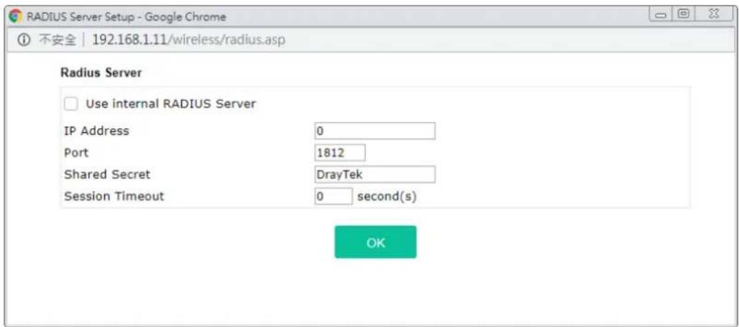
Available settings are explained as follows:
| Item | Description |
| Use internal RADIUS Server | There is a RADIUS server built in VigorAP 1000C which is used to authenticate the wireless client connecting to the access point. Check this box to use the internal RADIUS server for wireless security.Besides, if you want to use the external RADIUS server for authentication, do not check this box.Please refer to the section, IV-1-1 RADIUS Server to configure settings for internal server of VigorAP 1000C. |
| IP Address Enter the IP address of external RADIUS server. | |
| Port | The UDP port number that the external RADIUS server is using. The default value is 1812, based on RFC 2138. |
| Shared Secret The external RADIUS server and client share a secret that is used to authenticate the messages sent between them. Both sides must be configured to use the same shared secret. | |
| Session Timeout Set the maximum time of service provided before re-authentication.Set to zero to perform another authentication immediately after the first authentication has successfully completed. (The unit is second.) | |
After finishing this web page configuration, please click OK to save the settings.
II-3-3 Access Control
For additional security of wireless access, the Access Control facility allows you to restrict the network access right by controlling the wireless LAN MAC address of client. Only the valid MAC address that has been configured can access the wireless LAN interface. By clicking the Access Control, a new web page will appear, as depicted below, so that you could edit the clients' MAC addresses to control their access rights (deny or allow).
Wireless LAN (2.4GHz) >> Access Control
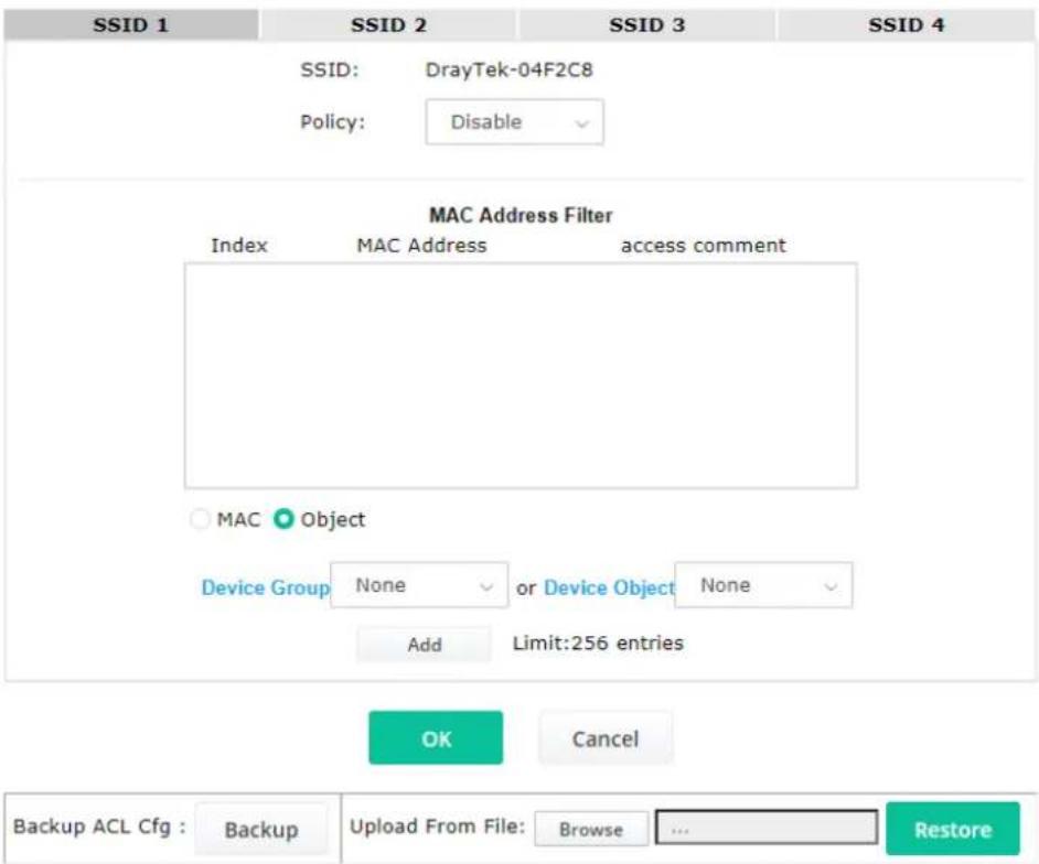
Available settings are explained as follows:
| Item | Description |
Policy Select to enable any one of the following policy or disable the policy.Choose Activate MAC address filter to type in the MAC addresses for other clients in the network manually. Choose Blocked MAC address filter, so that all of the devices with the MAC addresses listed on the MAC Address Filter table will be blocked and cannot access into VigorAP 1000C.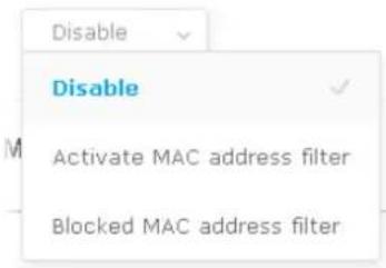 | |
MAC Address Filter Display all MAC addresses that are edited before.
| MAC Client's MAC Address | - Manually enter the MAC address of wireless client.Add - Add a new MAC address into the list.Delete - Delete the selected MAC address in the list.Edit - Edit the selected MAC address in the list. |
| Object In addition to enter the MAC address of the device manually, you can | Device Group - Select one of the existed device groups and click Add. All the devices belonging to the selected group will be shown on the MAC Address Filter table.Device Object - Select one of the existed device object and click Add. The MAC address of the device will be shown on the MAC Address Filter table. |
| Cancel Give up the access control set up. | |
| Backup | Click it to store the settings (MAC addresses on MAC Address Filter table) on this page as a file. |
| Restore | Click it to restore the settings (MAC addresses on MAC Address Filter table) from an existed file. |
After finishing this web page configuration, please click OK to save the settings.
II-3-4 WPS
Open Wireless LAN>>WPS to configure the corresponding settings.
Wireless LAN (2.4GHz) >> WPS (Wi-Fi Protected Setup)
Enable WPS
Wi-Fi Protected Setup Information
| WPS Configured | Yes |
| WPS SSID | DrayTek-04F2C8 |
| WPS Auth Mode | WPA3/WPA2 Personal |
| WPS Encrypt Type | AES |
Device Configure
| Configure via Push Button | Start PBC | |
| Configure via Client PinCode | Start PIN |
Status: The Authentication Mode is NOT WPA2/WPA Personal!!
Note: WPS can help your wireless client automatically connect to the Access point.
: WPS is Disabled.
2: WPS is Enabled.
C2: Waiting for WPS requests from wireless clients.
Available settings are explained as follows:
| Item | Description |
| Enable WPS Check this box to enable WPS setting. | |
| WPS Configured Display related system information for WPS. If the wireless security | |
| (encryption) function of VigorAP 1000C is properly configured, you can see 'Yes' message here. | |
| WPS SSID Display current selected SSID. | |
| WPS Auth Mode Display current authentication mode of the VigorAP 1000C. Only WPA2/PSK and WPA/PSK support WPS. | |
| WPS Encrypt Type Display encryption mode (None, WEP, TKIP, AES, etc.) of VigorAP 1000C. | |
| Configure via Push Button | Click Start PBC to invoke Push-Button style WPS setup procedure. VigorAP 1000C will wait for WPS requests from wireless clients about two minutes. Both ACT and 2.4G WLAN LEDs on VigorAP 1000C will blink quickly when WPS is in progress. It will return to normal condition after two minutes. (You need to setup WPS within two minutes) |
| Configure via Client PinCode | Type the PIN code specified in wireless client you wish to connect, and click Start PIN button. Both ACT and 2.4G WLAN LEDs on VigorAP 1000C will blink quickly when WPS is in progress. It will return to normal condition after two minutes. (You need to setup WPS within two minutes). |
II-3-5 Advanced Setting
This page is to determine which algorithm will be selected for wireless transmission rate.
Wireless LAN (2.4GHz) >> Advanced Setting
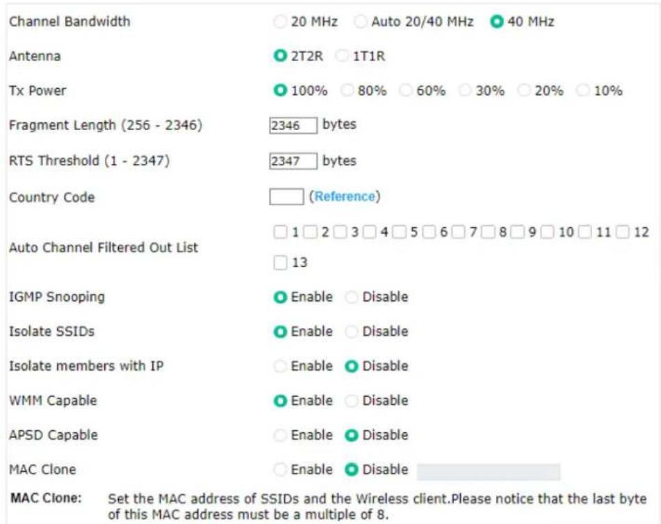
Note: Fragment Length takes effect when mode is "11b Only" or "Mixed(11b+11g)".

Available settings are explained as follows:
| Item | Description |
| Channel Bandwidth 20 MHz- The device will use 20MHz for data transmission and receiving between the AP and the stations. | |
| Antenna(for 2.4GHz only) | VigorAP can be attached with two antennas to have good data transmission via wireless connection. However, if you have only one antenna attached, please choose 1T1R. |
| Tx Power | The default setting is the maximum (100%). Lowering down the valuemay degrade range and throughput of wireless. |
| Fragment Length | Set the Fragment threshold of wireless radio. Do not modify default value if you don't know what it is, default value is 2346. |
| RTS Threshold Minimize | the collision (unit is bytes) between hidden stations to improve wireless performance.Set the RTS threshold of wireless radio. Do not modify default value if you don't know what it is, default value is 2347. |
| Country Code | VigorAP broadcasts country codes by following the 802.11d standard. However, some wireless stations will detect / scan the country code to prevent conflict occurred. If conflict is detected, wireless station will be warned and is unable to make network connection. Therefore, changing the country code to ensure successful network connection will be necessary for some clients. |
| Auto Channel Filtered Out List | The selected wireless channels will be discarded if AutoSelect is selected as Channel selection mode in Wireless LAN>>General Setup. |
| IGMP Snooping | Click Enable to enable IGMP Snooping. Multicast traffic will be forwarded to ports that have members of that group. Disabling IGMP snooping will make multicast traffic treated in the same manner as broadcast traffic. |
| Isolate SSIDs | The default setting is "Enable". It means that the wireless client using 2.4GHz band is unable to connect to the wireless client with 5GHz band, and vice versa.For WLAN 2.4GHz and 5GHz set with the same SSID name:No matter such function is enabled or disabled, clients using WLAN 2.4GHz and 5GHz can communicate for each other if Isolate Member (in Wireless LAN>>General Setup) is NOT enabled for such SSID.Yet, if the function of Isolate Member (in Wireless LAN>>General Setup) is enabled for such SSID, clients using WLAN 2.4GHz and 5GHz will be unable to communicate with each other. |
| Isolate members with IP | The default setting is "Disable".If it is enabled, VigorAP will isolate different wireless clients according to their IP address(es). |
| WMM Capable | To apply WMM parameters for wireless data transmission, please click the Enable radio button. |
| APSD Capable | APSD (automatic power-save delivery) is an enhancement over the power-save mechanisms supported by Wi-Fi networks. It allows devices to take more time in sleeping state and consume less power to improve the performance by minimizing transmission latency.The default setting is Disable. |
| MAC Clone (for 2.4GHz only) | Click Enable and manually enter the MAC address of the device with SSID 1. The MAC address of other SSIDs will change based on this MAC address. |
After finishing this web page configuration, please click OK to save the settings.
II-3-6 AP Discovery
VigorAP 1000C can scan all regulatory channels and find working APs in the neighborhood. Based on the scanning result, users will know which channel is clean for usage. Also, it can be used to facilitate finding an AP for a WDS link. Notice that during the scanning process (about 5 seconds), no client is allowed to connect to VigorAP.
This page is used to scan the existence of the APs on the wireless LAN. Please click Scan to discover all the connected APs.
Wireless LAN (2.4GHz) >> Access Point Discovery
Access Point List
| Select | Index | SSID | BSSID | RSSI | Channel | Encryption | Authentication |
| 1 | 12:1D:AA:04:F0:6C | 25%(-84dbm) | 11 | AES | WPA2/PSK | ||
| 2 | Tling_VC_2... | 00:1D:AA:E4:8E:80 | 11%(-88dbm) | 11 | TKIP/AES | Mixed(WPA+WPA2)/PSK | |
| 3 | DrayTek-04... | 00:1D:AA:04:F0:6C | 22%(-85dbm) | 11 | TKIP/AES | Mixed(WPA+WPA2)/PSK | |
| 4 | rd8-ap1000... | 06:1D:AA:04:F0:6C | 32%(-82dbm) | 11 | TKIP/AES | WPA2/PSK | |
| 5 | 00:1D:AA:5E:D9:58 | 39%(-80dbm) | 11 | TKIP/AES | Mixed(WPA+WPA2)/PSK | ||
| 6 | rdBrd8 | 00:1D:AA:57:5D:38 | 53%(-76dbm) | 11 | TKIP/AES | Mixed(WPA+WPA2)/PSK | |
| 7 | Ting_VC_2... | 00:1D:AA:3D:4F:14 | 39%(-80dbm) | 11 | TKIP/AES | Mixed(WPA+WPA2)/PSK | |
| 8 | Ting_VC_2... | 02:50:7F:C1:91:E7 | 8%(-89dbm) | 11 | TKIP/AES | Mixed(WPA+WPA2)/PSK | |
| 9 | DrayTek-LA... | 00:1D:AA:22:33:44 | 15%(-87dbm) | 11 | TKIP/AES | Mixed(WPA+WPA2)/PSK | |
| 10 | V2926_PQC... | 00:1D:AA:04:F0:D6 | 8%(-89dbm) | 11 | AES | WPA2/PSK | |
| 11 | staffs | 02:50:7F:C1:7F:1D | 91%(-64dbm) | 1 | AES | WPA2/PSK | |
| 12 | staffs | 02:50:7F:C1:7E:CB | 28%(-83dbm) | 1 | AES | WPA2/PSK | |
| 13 | guests | 02:50:7F:D1:7F:1D | 90%(-65dbm) | 1 | AES | WPA2/PSK | |
| 14 | guests | 02:50:7F:D1:7E:CB | 32%(-82dbm) | 1 | AES | WPA2/PSK | |
| 15 | guests | 02:50:7F:D1:7E:EC | 4%(-91dbm) | 1 | AES | WPA2/PSK | |
| 16 | DrayTek | 00:1D:AA:92:6F:18 | 2%(-93dbm) | 6 | TKIP/AES | Mixed(WPA+WPA2)/PSK | |
| 17 | DrayTek | 00:1D:AA:CB:A3:10 | 8%(-89dbm) | 6 | TKIP/AES | Mixed(WPA+WPA2)/PSK | |
| 18 | DrayTek | 00:1D:AA:94:ED:E0 | 84%(-67dbm) | 6 | TKIP/AES | Mixed(WPA+WPA2)/PSK | |
| 19 | DrayTek | 00:50:7F:F0:D5:B5 | 11%(-88dbm) | 11 | TKIP/AES | Mixed(WPA+WPA2)/PSK | |
| 20 | RD8_GW_24G... | 00:1D:AA:5B:A0:C8 | 5%(-90dbm) | 13 | TKIP/AES | Mixed(WPA+WPA2)/PSK | |
| 21 | staffs_2 | 00:1D:AA:62:0F:E8 | 19%(-86dbm) | 3 | AES | WPA2/PSK | |
| 22 | staffs_2 | 02:50:7F:C1:7E:CF | 92%(-63dbm) | 3 | TKIP/AES | WPA2/PSK | |
| 23 | guests_2 | 02:50:7F:D1:7E:CF | 91%(-64dbm) | 3 | TKIP/AES | WPA2/PSK | |
| 24 | rdBrd8 | 00:1D:AA:7F:5D:8C | 2%(-93dbm) | 4 | TKIP/AES | Mixed(WPA+WPA2)/PSK | |
| 25 | guests_2 | 00:1D:AA:62:0F:E9 | 0%(-95dbm) | 3 | AES | WPA2/PSK | |
| 26 | 12:1D:AA:63:2C:00 | 25%(-84dbm) | 9 | AES | WPA2/PSK | ||
| 27 | PQC Mesh T... | 00:1D:AA:63:2C:00 | 22%(-85dbm) | 9 | AES | WPA2/PSK | |
| 28 | PQC-SmartP... | 00:1D:AA:04:F0:DC | 0%(-95dbm) | 11 | AES | Mixed(WPA+WPA2)/PSK | |
| 29 | DrayTek-LA... | 02:1D:AA:20:33:44 | 0%(-95dbm) | 11 | TKIP/AES | Mixed(WPA+WPA2)/PSK | |
| 30 | V2860Ln_PQ... | 00:1D:AA:DD:75:70 | 0%(-95dbm) | 11 | TKIP/AES | Mixed(WPA+WPA2)/PSK |
Each item is explained as follows:
| Item | Description |
| SSID Display the SSID of the AP scanned by VigorAP 1000C. | |
| BSSID | Display the MAC address of the AP scanned by VigorAP 1000C. |
| RSSI Display the signal strength of the access point. RSSI is the abbreviation of Received Signal Strength Indication. | |
| Channel Display the wireless channel used for the AP that is scanned by VigorAP 1000C. | |
| Encryption Display the encryption mode for the scanned AP. | |
| Authentication Display the authentication type that the scanned AP applied. | |
| Scan It is used to discover all the connected AP. The results will be shown on the box above this button | |
| AP's MAC Address / AP's SSID | Display the MAC address and SSID of the AP selected from the Access Point. |
| Add Click it to add the AP selected from the Access Point List (with the same channel width) to the WDS Settings as peer's setting. | |
II-3-7 WDS AP Status
VigorAP 1000C can display the status such as MAC address, physical mode, power save and bandwidth for the working AP connected with WDS. Click Refresh to get the newest information.
Wireless LAN (5GHz) >> WDS AP Status
WDS AP List
| AID | MAC Address | 802.11 Physical Mode | Power Save | Bandwidth |
Refresh
II-3-8 Bandwidth Management
The downstream or upstream from FTP, HTTP or some P2P applications will occupy large of bandwidth and affect the applications for other programs. Please use Bandwidth Management to make the bandwidth usage more efficient.
Wireless LAN (2.4GHz) >> Bandwidth Management
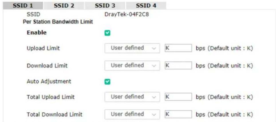
Note: 1. Download : Traffic going to any station. Upload : Traffic being sent from a wireless station. 2. Allow auto adjustment could make the best utilization of available bandwidth.

Available settings are explained as follows:
| Item | Description |
| SSID Display the specific SSID name. | |
| Enable Check this box to enable the bandwidth management for clients. | |
| Upload Limit Define the maximum speed of the data uploading which will be used for the wireless stations connecting to Vigor device with the same SSID.Use the drop down list to choose the rate. If you choose User defined, you have to specify the rate manually. | |
| Download Limit Define the maximum speed of the data downloading which will be | |
| used for the wireless station connecting to Vigor device with the same SSID.Use the drop down list to choose the rate. If you chooseUser defined, you have to specify the rate manually. | |
| Auto Adjustment | Check this box to have the bandwidth limit determined by the system automatically. |
| Total Upload LimitWhen Auto Adjustment is checked, the value defined here will be treated as the total bandwidth shared by all of the wireless stations with the same SSID for data uploading. | |
| Total Download LimitWhen Auto Adjustment is checked, the value defined here will be treated as the total bandwidth shared by all of the wireless stations with the same SSID for data downloading. | |
After finishing this web page configuration, please click OK to save the settings.
II-3-9 Airtime Fairness
Airtime fairness is essential in wireless networks that must support critical enterprise applications.
Most of the applications are either symmetric or require more downlink than uplink capacity; telephony and email send the same amount of data in each direction, while video streaming and web surfing involve more traffic sent from access points to clients than the other way around. This is essential for ensuring predictable performance and quality-of-service, as well as allowing 802.11n and legacy clients to coexist on the same network. Without airtime fairness, offices using mixed mode networks risk having legacy clients slow down the entire network or letting the fastest client(s) crowd out other users.
With airtime fairness, every client at a given quality-of-service level has equal access to the network's airtime.
The wireless channel can be accessed by only one wireless station at the same time.
The principle behind the IEEE802.11 channel access mechanisms is that each station has equal probability to access the channel. When wireless stations have similar data rate, this principle leads to a fair result. In this case, stations get similar channel access time which is called airtime.
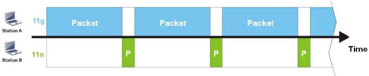
However, when stations have various data rate (e.g., 11g, 11n), the result is not fair. The slow stations (11g) work in their slow data rate and occupy too much airtime, whereas the fast stations (11n) become much slower.
Take the following figure as an example, both Station A(11g) and Station B(11n) transmit data packets through VigorAP 1000C. Although they have equal probability to access the wireless channel, Station B(11n) gets only a little airtime and waits too much because Station A(11g) spends longer time to send one packet. In other words, Station B(fast rate) is obstructed by Station A(slow rate).
flowchart
graph LR
    A["Station A"] -->|11g| B["Packet"]
    B --> C["11n"]
    C --> D["P"]
    D --> E["Packet"]
    E --> F["11n"]
    F --> G["P"]
    G --> H["Packet"]
    H --> I["11n"]
    I --> J["P"]
    J --> K["Time"]
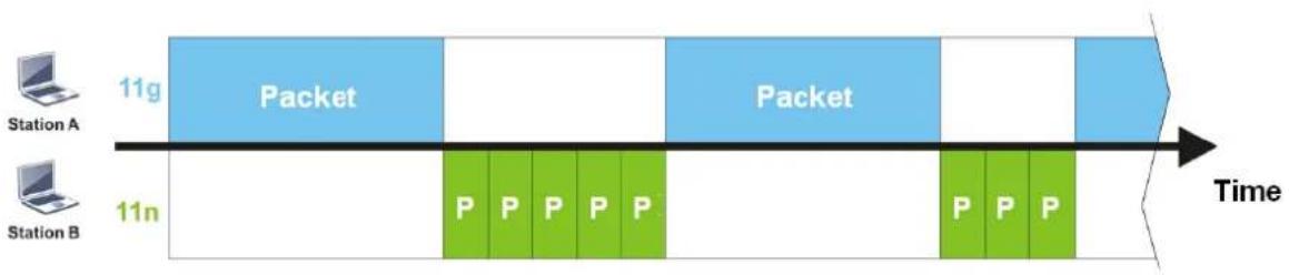
To improve this problem, Airtime Fairness is added for VigorAP 1000C. Airtime Fairness function tries to assign similar airtime to each station (A/B) by controlling TX traffic. In the following figure, Station B(11n) has higher probability to send data packets than Station A(11g). By this way, Station B(fast rate) gets fair airtime and it's speed is not limited by Station A(slow rate).
flowchart
graph LR
    A["Station A"] --> B["11g Packet"]
    C["Station B"] --> D["11n P P P P P"]
    B --> E["Time"]
    D --> F["Time"]
It is similar to automatic Bandwidth Limit. The dynamic bandwidth limit of each station depends on instant active station number and airtime assignment. Please note that Airtime Fairness of 2.4GHz and 5GHz are independent. But stations of different SSIDs function together, because they all use the same wireless channel. IN SPECIFIC ENVIRONMENTS, this function can reduce the bad influence of slow wireless devices and improve the overall wireless performance.
Suitable environment:
(1) Many wireless stations.
(2) All stations mainly use download traffic.
(3) The performance bottleneck is wireless connection.
Wireless LAN (2.4GHz) >> Airtime Fairness

Enable Airtime Fairness
Triggering Client Number 2 (2 \~ 128, Default: 2)
Note: Please enable or disable this function according to the real situation and user experience. It is NOT suitable for all environments.

Cancel
Available settings are explained as follows:
| Item | Description |
| Enable Airtime Fairness | Try to assign similar airtime to each wireless station by controlling TX traffic.Airtime Fairness – Click the link to display the following screen of airtime fairness note.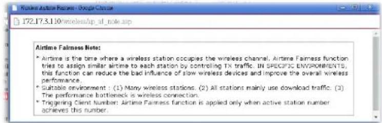 Triggering Client Number –Airtime Fairness function is applied only when active station number achieves this number. Triggering Client Number –Airtime Fairness function is applied only when active station number achieves this number. |
After finishing this web page configuration, please click OK to save the settings.
Note:
Airtime Fairness function and Bandwidth Limit function should be mutually exclusive. So their webs have extra actions to ensure these two functions are not enabled simultaneously.
II-3-10 Station Control
Station Control is used to specify the duration for the wireless client to connect and reconnect VigorAP. If such function is not enabled, the wireless client can connect VigorAP until it shuts down.
Such feature is especially useful for free Wi-Fi service. For example, a coffee shop offers free Wi-Fi service for its guests for one hour every day. Then, the connection time can be set as "1 hour" and reconnection time can be set as "1 day". Thus, the guest can finish his job within one hour and will not occupy the wireless network for a long time.
Note:
Up to 300 Wireless Station records are supported by VigorAP.
Wireless LAN (2.4GHz) >> Station Control
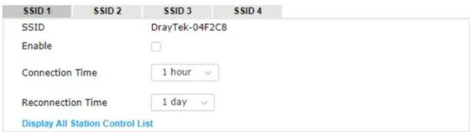
Note: Once the feature is enabled, the connection time quota will apply to each wireless client (identified by MAC address).

Available settings are explained as follows:
| Item | Description |
| SSID Display the SSID that the wireless station will use it to connect with Vigor router. | |
| Enable Check the box to enable the station control function. | |
| Connection Time / Reconnection Time | Use the drop down list to choose the duration for the wireless client connecting /reconnecting to Vigor device. Or, type the duration manually when you choose User defined. |
| Display All Station Control List | All the wireless stations connecting to Vigor router by using such SSID will be listed on Station Control List. |
After finishing all the settings here, please click OK to save the configuration.
II-3-11 Roaming
The network signal for a single wireless access point might be limited by its coverage range. Therefore, if you want to expand the wireless network in a large exhibition with a quick method, you can install multiple access points with enabling the Roaming feature for each AP to reach the purpose of expanding wireless signals seamlessly.
These access points connecting for each other shall be verified by pre-authentication. This page allows you to enable the roaming feature and the pre-authentication.
Wireless LAN (2.4GHz) >> Roaming
Fast Transition Roaming
Enable 802.11r
AP-assisted Client Roaming Parameters
Minimum Basic Rate 1 Mbps
Disable RSSI Requirement
○ Strictly Minimum RSSI -73 dBm (42 %) (Default: -73)
Minimum RSSI -66 dBm (60 %) (Default: -66)
with Adjacent AP RSSI over 5 dB (Default: 5)
Fast Roaming(WPA2 Enterprise)
Enable PMK Caching : Cache Period 10 minutes (10 \~ 600, Default: 10) Pre-Authentication
Available settings are explained as follows:
| Item | Description |
| Fast Transition Roaming | Enable 802.11r - Check to enable the function of fast roaming to switch between the hotspots fastly and securely. |
| AP-assisted Client Roaming Parameters | When the link rate of wireless station is too low or the signal received by the wireless station is too worse, VigorAP 1000C will automatically detect (based on the link rate and RSSI requirement) and cut off the network connection for that wireless station to assist it to connect another Wireless AP to get better signal.Minimum Basic Rate - Check the box to use the drop down list to specify a basic rate (Mbps). When the link rate of the wireless station is below such value, VigorAP 1000C will terminate the network connection for that wireless station.Disable RSSI Requirement - If it is selected, VigorAP will notterminate the network connection based on RSSI.Strictly Minimum RSSI - VigorAP uses RSSI (received signal strength indicator) to decide to terminate the network connection of wireless station. When the signal strength is below the value (dBm) set here, VigorAP 1000C will terminate the network connection for that wireless station.Minimum RSSI - When the signal strength of the wireless station is below the value (dBm) set here and adjacent AP (must be DrayTek AP and support such feature too) with higher signal strength value (defined in the field of With Adjacent AP RSSI over) is detected by VigorAP 1000C, VigorAP 1000C will terminate the network connection for that wireless station. Later, the wireless station can connect to the adjacent AP (with better RSSI).With Adjacent AP RSSI over – Specify a value as a threshold. |
| Fast Roaming (WPA2/802.1x) | Enable – Check the box to enable fast roaming configuration.PMK Caching - Set the expire time of WPA2 PMK (Pairwise master key) cache. PMK Cache manages the list from the BSSIDs in the associated SSID with which it has pre-authenticated. Such feature is available for WPA2/802.1 mode.Pre-Authentication - Enables a station to authenticate to multiple APs for roaming securer and faster. With the pre-authentication procedure defined in IEEE 802.11i specification, the pre-four-way-handshake can reduce handoff delay perceivable by a mobile node. It makes roaming faster and more secure. (Only valid in WPA2)Enable - Enable IEEE 802.1X Pre-Authentication.Disable - Disable IEEE 802.1X Pre-Authentication. |
After finishing this web page configuration, please click OK to save the settings.
II-3-12 Band Steering (for Wireless LAN (2.4GHz))
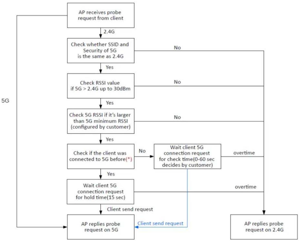
Band Steering detects if the wireless clients are capable of 5GHz operation, and steers them to that frequency. It helps to leave 2.4GHz band available for legacy clients, and improves users experience by reducing channel utilization.
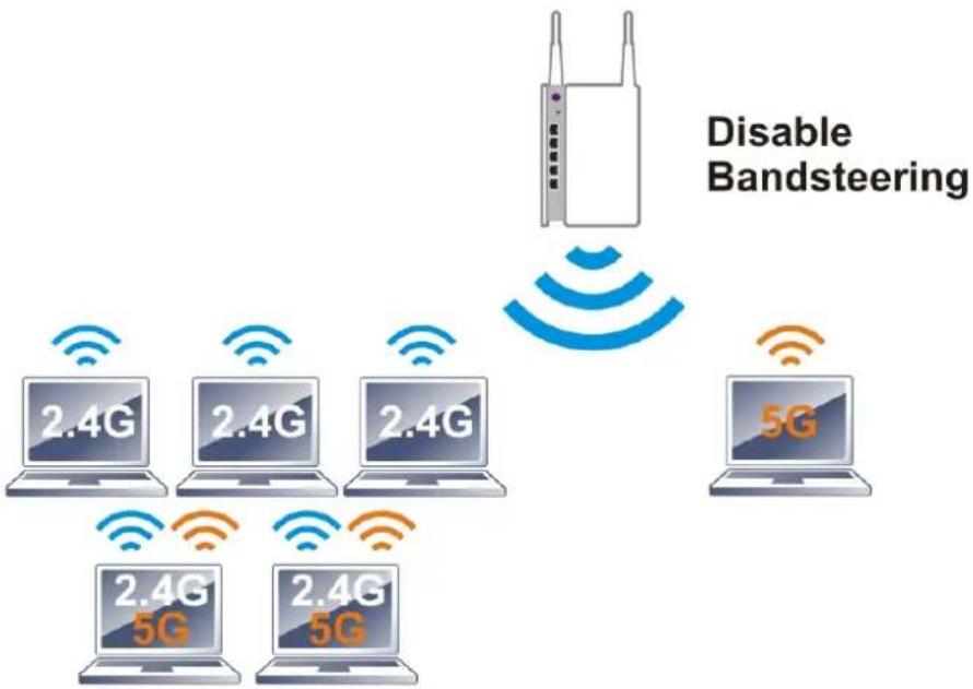
flowchart
graph TD
    A["Disabling Bandsteering"] --> B["Router"]
    B --> C["5G"]
    C --> D["2.4G 5G"]
    C --> E["2.4G 5G"]
    C --> F["2.4G 5G"]
    C --> G["2.4G 5G"]
    style A fill:#f9f,stroke:#333
    style B fill:#ccf,stroke:#333
    style C fill:#cfc,stroke:#333
    style D fill:#fcc,stroke:#333
    style E fill:#cff,stroke:#333
    style F fill:#ffc,stroke:#333
    style G fill:#fcc,stroke:#333
If dual-band is detected, the AP will let the wireless client connect to less congested wireless LAN, such as 5GHz to prevent from network congestion.
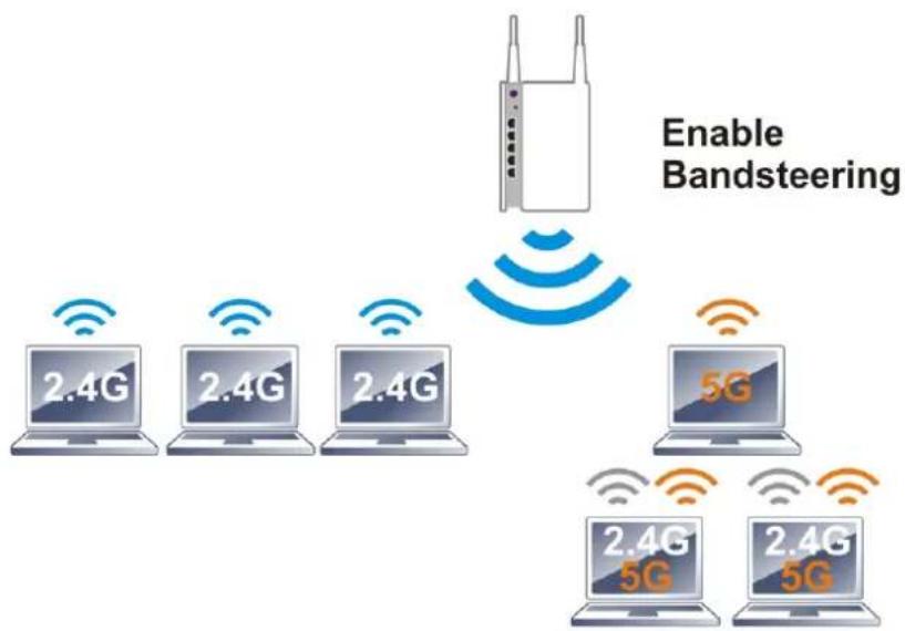
Note:
To make Band Steering work successfully, SSID and security on 2.4GHz also MUST be broadcasted on 5GHz / 5GHz-2.
Open Wireless LAN (2.4GHz)>>Band Steering to get the following web page:
Wireless LAN (2.4GHz) >> Band Steering
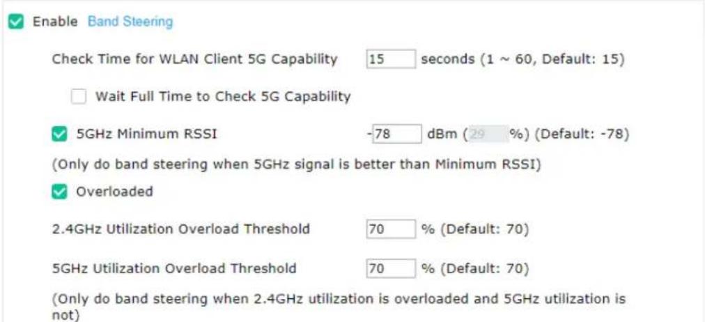
Note: Please setup at least one pair of 2.4GHz and 5GHz Wireless LAN with the same SSID and security.

Available settings are explained as follows:
| Item | Description |
| Enable Band Steering | If it is enabled, VigorAP will detect if the wireless client is capable of dual-band or not within the time limit.Check Time.... - If the wireless station does not have the capability of 5GHz network connection, the system shall wait and check for several seconds (15 seconds, in default) to make the 2.4GHz network connection. Specify the time limit for VigorAP to detect the wireless client.Wait Full Time to Check 5G Capability - If enabled, the client trying to connect to wireless network 2.4G has to wait for a few seconds (defined in Check Time... above) to check if the connecting device has the 5G capability. If no 5G capability, the client will be directed to the wireless 2.4G network.5GHz Minimum RSSI - The wireless station has the capability of 5GHz network connection, yet the signal performance might not be satisfied. Therefore, when the signal strength is below the value set here while the wireless station connecting to VigorAP, VigorAP will allow the client to connect to 2.4GHz network.Overloaded - If it is enabled, VigorAP will activate the band steeringaccording to the conditions set below.2.4GHz Utilization Overload Threshold – The default setting is 70%. It can define the network congestion for 2.4GHz.5GHz Utilization Overload Threshold – The default setting is 70%. It can define the network congestion for 5GHz.When the utilization of 2.4GHz is higher than the specified threshold and the utilization of 5GHz is lower than the specified threshold, VigorAP will steer the client to connect to 5GHz network. |
After finishing this web page configuration, please click OK to save the settings.
Below shows how Band Steering works.
flowchart
graph TD
    A["AP receives probe request from client"] --> B["2.4G"]
    B --> C["Check whether SSID and Security of 5G is the same as 2.4G"]
    C -->|Yes| D["Check RSSI value if 5G > 2.4G up to 30dBm"]
    C -->|No| E["Wait client 5G connection request for hold time(15 sec)"]
    D -->|Yes| F["Check 5G RSSI if it's larger than 5G minimum RSSI (configured by customer)"]
    D -->|No| G["Wait client 5G connection request for check time(0-60 sec decides by customer)"]
    F -->|Yes| H["Wait client 5G connection request for hold time(15 sec)"]
    F -->|No| I["Client send request"]
    H -->|Yes| J["AP replies probe request on 5G"]
    H -->|No| K["AP replies probe request on 2.4G"]
    I --> L["Client send request"]
    style A fill:#f9f,stroke:#333
    style K fill:#f9f,stroke:#333
* AP will clear the 5G history station list every 2.5 mins.
How to Use Band Steering?
- Open Wireless LAN(2.4GHz)>>Band Steering.
- Check the box of Enable Band Steering and use the default value (15) for check time setting.
Wireless LAN (2.4GHz) >> Band Steering

Enable Band Steering
Check Time for WLAN Client 5G Capability 15 seconds (1 \~ 60, Default: 15)
□ Wait Full Time to Check 5G Capability
- Click OK to save the settings.
- Open Wireless LAN (2.4GHz)>>General Setup, Wireless LAN (5GHz)>>General Setup, and Wireless LAN (5GHz-2)>>General Setup. Configure SSID as ap1000-BandSteering for these pages. Click OK to save the settings.
Wireless LAN (2.4GHz) >> General Setup
General Setting (IEEE 802.11)

Enable Wireless LAN
Enable Client Limit 128 (3 \~ 128, default: 128)
Enable Client Limit per SSID (3 \~ 128, default: 128)
Wireless LAN (5GHz) >> General Setup
Mode : Mixed(11b+11q+11n)
Channel : 2417MHz (Channel 2) ▼ (Active Chani
Extension Channel : 2437MHz (Channel 6)
General Setting (IEEE 802.11)
Enable Wireless LAN
Enable Client Limit 128 (3 \~ 128, default: 128)
Enable Client Limit per SSID (3 \~ 128, default: 128)
Mode : Mixed(11a+11n+11ac)
Channel : 5260MHz (Channel 52) (Active Channel: +4)
Details : [DFS] 20/40MHz Ext Ch: 56, 80MHz Center Ch: 58
Enable 2 Subnet (Simulate 2 APs)
Enable Hide SSID SSID Subnet Isolate LAN Isolate Member VLAN ID (0: Untagged)
ap1000-BandSteering
Wireless LAN (5GHz 2) >> General Setup
General Setting (IEEE 802.11)
Same value for 2.4GHz, 5GHz and 5GHz-2
Enable Wireless LAN
Enable Client Limit 120 (3 - 120, default: 120)
Enable Client Limit per SSID (3 \~ 128, default: 128)
Mode : Mixed (11a+11n+11ac)
Channel : 5500MHz (Channel 100) √ (Active Channel: 100)
Details : [OFS] 20/40MHz Ext Ch:104, 80MHz Center Ch:106
Enable 2 Subnet (Simulate 2 APs)

- Open Wireless LAN (2.4GHz)>>General Setup, Wireless LAN (5GHz)>>General Setup, and Wireless LAN (5GHz-2)>>General Setup. Configure Security as 12345678 for these pages. Click OK to save the settings.
Wireless LAN (2.4GHz) >> Security Settings
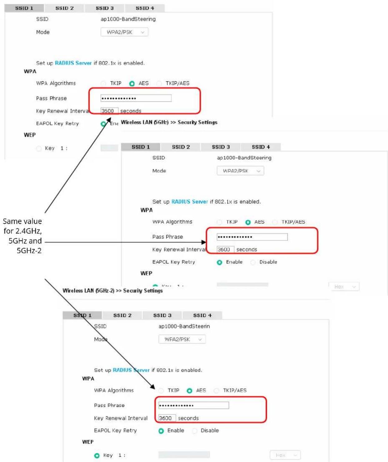
- Now, VigorAP 1000C will let the wireless clients connect to less congested wireless LAN, such as 5GHz to prevent from network congestion.
II-3-13 Station List
Station List provides the information related to the number of clients connecting to VigorAP, used bandwidth and the statistics of the AP device OS. Besides, users can create access control policies, device objects and set black & white list for
II-3-13-1 Connected Number
This page lists the graph for the number of wireless stations connected to this Access Point with different time phases.
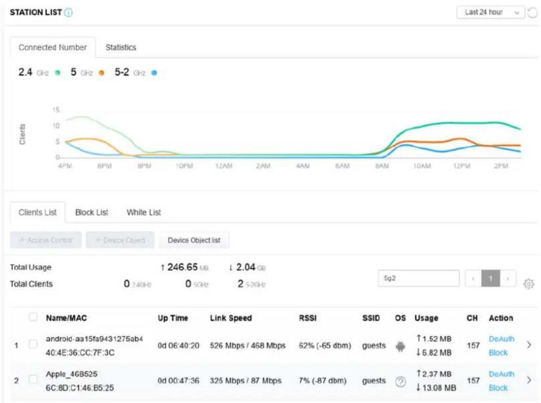
line
| Device Object | Time | Up Time | Link Speed | RSSI | OS | Usage | CH | Action | | ------------- | -------- | ------- | ---------- | ------ | ------ | ------ | ----- | ------ | | Android | 06:40:20 | 0d | 526 Mbps / 468 Mbps | 62% (-65 dbm) | guests | ↑1.52 MB | 157 | DeAuth Block | | Apple | 00:47:36 | 0d | 325 Mbps / 87 Mbps | 7% (-87 dbm) | guests | ↑2.37 MB | 157 | DeAuth Block |II-3-13-2 Statistics
The number of detected devices and the number of device(s) passed/blocked according to the policy specified in Mobile Device Management>>Policy can be illustrated as doughnut chart.
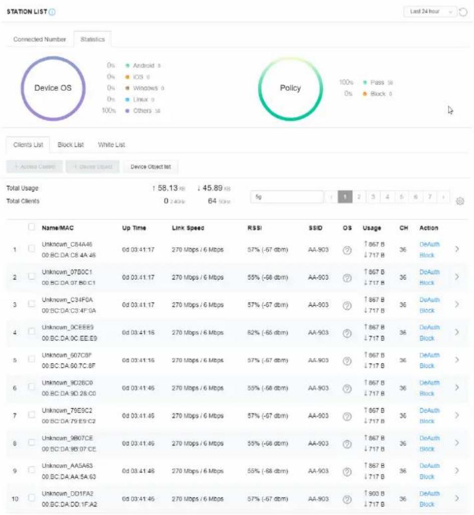
other
| Device | Time (ms) | | :--- | :--- | | Unknown_C84A46 | 0d 03:41:17 | | Unknown_07B0C1 | 0d 03:41:17 | | Unknown_C34F0A | 0d 03:41:17 | | Unknown_0CEEE9 | 0d 03:41:16 | | Unknown_607C0F | 0d 03:41:16 | | Unknown_8D2BC0 | 0d 03:41:45 | | Unknown_76E9C2 | 0d 03:41:45 | | Unknown_9B07CE | 0d 03:41:45 | | Unknown_AA5A63 | 0d 03:41:48 | | Unknown_DD1FA2 | 0d 03:41:45 | | Total Clients | 0 ≥ 40% | Link Speed | RSSI | | RS# | SSID | | OS | Usage | | Ch | Action | | ↑867 B ↓717 B | 36 DeAuth Block > | | ↑867 B ↓717 B | 36 DeAuth Block > | | ↑867 B ↓717 B | 36 DeAuth Block > | | ↑867 B ↓717 B | 36 DeAuth Block > | | ↑867 B ↓717 B | 36 DeAuth Block > | | ↑867 B ↓717 B | 36 DeAuth Block> | | ↑867 B ↓717 B | 36 DeAuth Block > | | ↑867 B ↓717 B | 36 DeAuth Block > | | ↑867 B ↓717 B | 36 DeAuth Block > | | ↑867 B ↓717 B | 36 DeAuth Block > | | ↑867 B ↓717 B | 36 DeAuth Block>II-3-13-3 Clients List
The client list displays all the stations connecting to VigorAP.
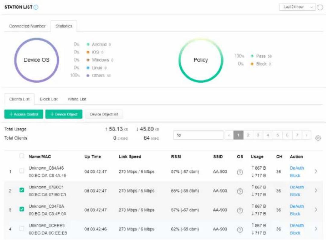
Available settings are explained as follows:
| Item | Description |
| +Access Control | It is available after choosing one of the entries (clients) on Clients List. |
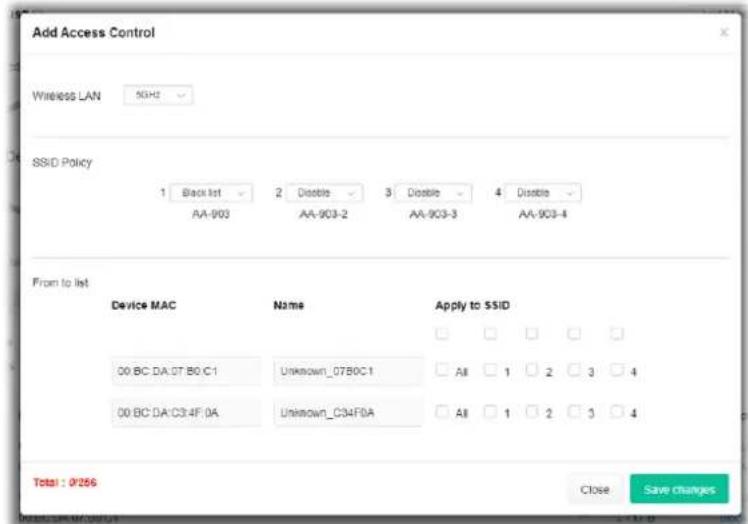 | |
| Wireless LAN - Specify the bandwidth for the access control list. SSID Policy - Set the policy for each SSID as black list or white list or disable. From to list - Display the clients available for applying this accesscontrol.Apply to SSID - Check All to make the device apply the policies to all SSIDs. Or select the one(s) to make the device apply the policies to the selected SSIDs.Close - Exit this page without saving any changes.Save changes - Save the changes and exit this page. | |
+Device Object To add a device to device object list, choose one of the entries (clients) on Clients List to enable the Device Object button. Click the button to open the following page.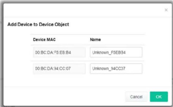 Check the information listed on the page. Change the MAC address or name of the selected entry if required. Then click OK and exit the page. Check the information listed on the page. Change the MAC address or name of the selected entry if required. Then click OK and exit the page. | |
Device Object list The existed device object profiles will be shown on the following page.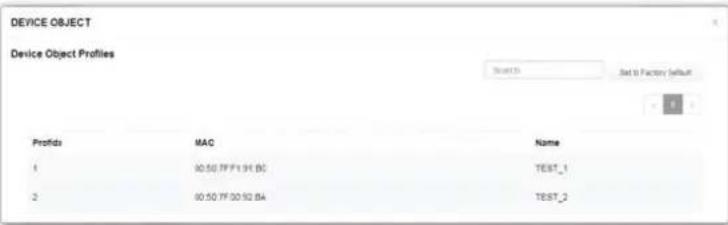 | |
| Clients List Display the stations connecting to this Vigor device.Total Usage - DisplayTotal Clients - Display the number of the clients using 2.4GHzName / MAC - Display the host name / MAC address of the connecting client.Up Time - Display the connection time.Link Speed- Display the link speed.RSSI - Display the RSSI value.SSID - Display the SSID the client used for connecting VigorAP.OS - Display the OS of the client.Usage - Display the bandwidth usage (up and down) of the client.CH - Display the channel used by the client.Action - Display the authentication method used by the client, and if it is on block list or white list. | |
II-3-13-4 Block List
This page displays information of the stations under block list.
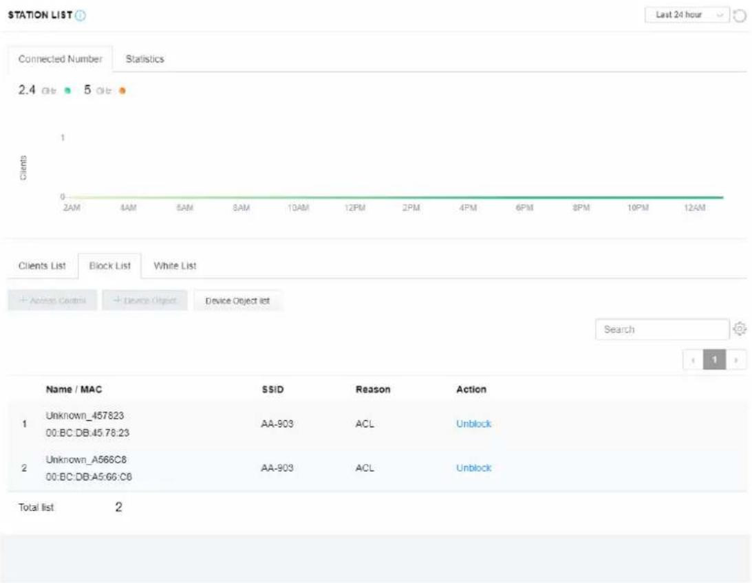
Available settings are explained as follows:
| Item | Description |
| Device Object list Click it to open the Device Object List dialog for reference. | 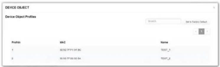 |
| Name / MAC | Display the host name / MAC Address for the connecting client. |
| SSID Display the SSID that the wireless client connects to. | |
| Reason Display the reference information. | |
| Action | Display the action that you can execute for the station.Unblock - Click to unblock the entry. |
II-3-13-5 White List
This page displays general information of the stations under white list.
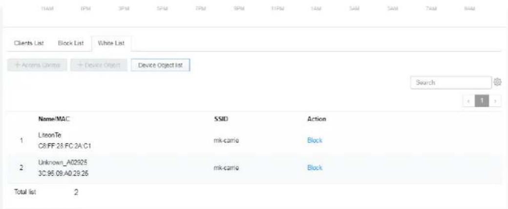
Available settings are explained as follows:
| Item | Description |
| Device Object list Click it to open the Device Object List dialog for reference. | 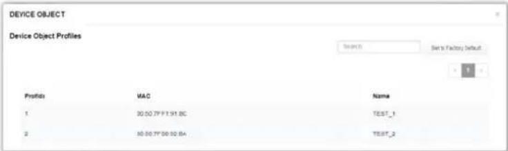 |
| Name / MAC | Display the host name / MAC Address for the connecting client. |
| SSID Display the SSID that the wireless client connects to. | |
| Action | Display the action that you can execute for the station.Block - Click to block the entry. |
II-4 Mesh Settings for Mesh Mode
When you choose Mesh as the operation mode, the Mesh menu with the settings of Mesh Setup, Mesh Status, Mesh Discovery, Configuration Sync, Support List and Mesh Syslog will be shown on the screen.
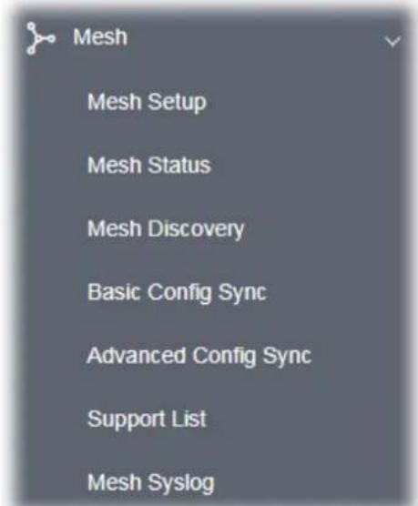
Please note that, within VigorMesh network,
the total number allowed for mesh nodes is 8 (including the mesh root)
• the maximum number of hop is 3
Refer to the following figure:
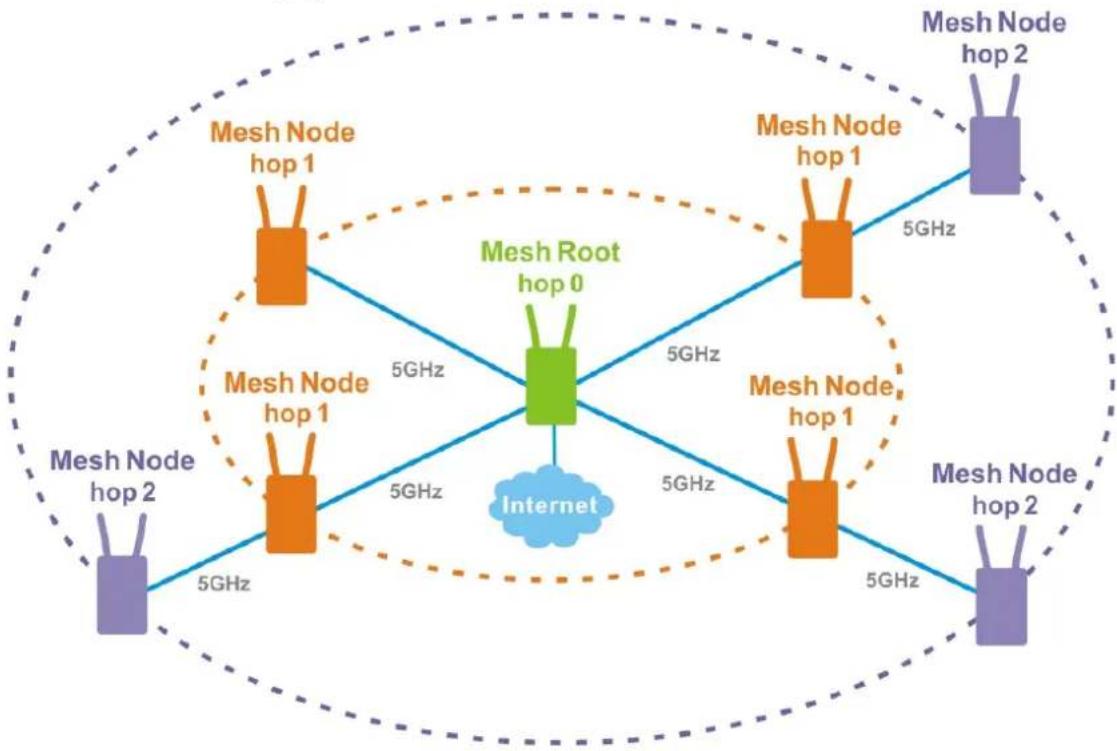
flowchart
graph TD
    A["Mesh Node hop 0"] -->|5GHz| B["Mesh Node hop 1"]
    A -->|5GHz| C["Mesh Node hop 2"]
    A -->|5GHz| D["Mesh Node hop 1"]
    A -->|5GHz| E["Mesh Node hop 2"]
    F["Internet"] --> A
    A -->|5GHz| G["Mesh Node hop 1"]
    A -->|5GHz| H["Mesh Node hop 2"]
    A -->|5GHz| I["Mesh Node hop 1"]
    A -->|5GHz| J["Mesh Node hop 2"]
    style A fill:#f9f,stroke:#333
    style B fill:#ccf,stroke:#333
    style C fill:#ccf,stroke:#333
    style D fill:#ccf,stroke:#333
    style E fill:#ccf,stroke:#333
    style F fill:#cfc,stroke:#333
    style G fill:#cfc,stroke:#333
    style H fill:#cfc,stroke:#333
    style I fill:#cfc,stroke:#333
    style J fill:#cfc,stroke:#333
For the mesh group set within VigorMesh network,
It must be composed by "1" Mesh Root and "0\~7" mesh nodes
(Roaming) Normally members in a mesh group use the same Wireless SSID/security
(Add) Only the mesh root can add a new mesh node into the mesh group
(Recover) A disconnected mesh node will automatically try to connect to another connected mesh node of the same group
Mesh Root and Mesh Node
Mesh Root indicates that VigorAP would be other AP's uplink connection. As a Mesh Root, VigorAP must connect to a gateway with Ethernet cable first to have an internet connection.
As a Mesh Node, VigorAP can connect to the mesh root or mesh node within the same mesh group via wireless network or physical connection with an Ethernet cable.
The following figure shows how VigorAP runs as MESH ROOT:
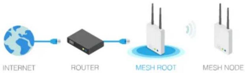
flowchart
graph LR
    A["INTERNET"] --> B["ROUTER"]
    B --> C["MESH ROOT"]
    C --> D["MESH NODE"]
The following figure shows how VigorAP runs as MESH NODE:
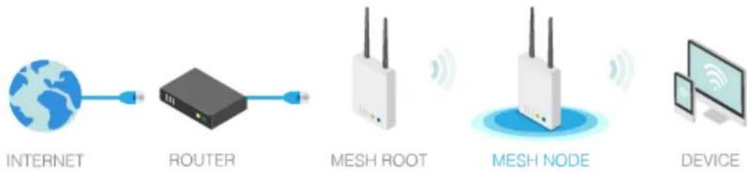
flowchart
graph LR
    A["INTERNET"] --> B["ROUTER"]
    B --> C["MESH ROOT"]
    C --> D["MESH NODE"]
    D --> E["DEVICE"]
II-4-1 Mesh Setup
Such page can determine the role of the VigorAP connecting to the computer physically. For a mesh root, you can search and specify mesh nodes as members under current mesh group.
Mesh >> Mesh Setup
General Setup
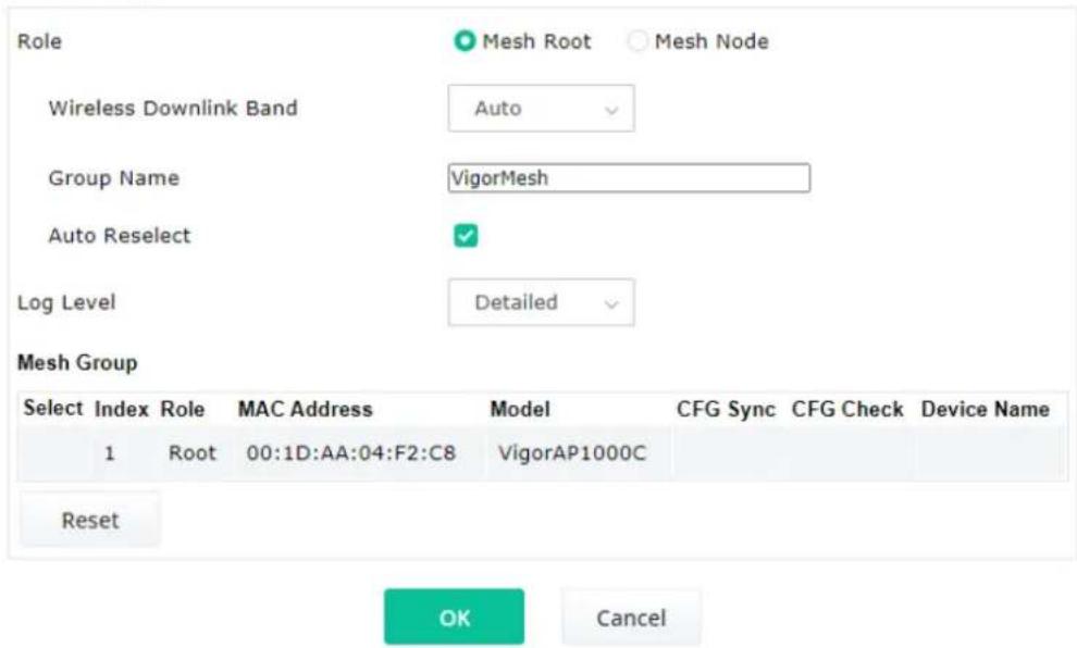
Add Mesh Node
Press Search button below to find and adopt the new node into Mesh group.
Search
Backup Mesh Config
Backup
Browse
...
Restore
Available settings are explained as follows:
| Item | Description |
| General Setup | |
| Role | Mesh Root – When VigorAP is connected to a Vigor router with a physical Ethernet cable, it can be set as mesh root to deliver the wireless signals to a mesh node AP.Mesh Node – As a mesh node, such VigorAP can pass the wireless connection signal to other mesh node or a remote device (PC, CPE, mobile phone).In addition, VigorAP can be searched by mesh root AP and join the mesh group of the root AP. The configuration set for mesh root can be applied to mesh node.Log Level – Choose Basic or Detailed. Related information will be shown on the Diagnostics>>System Log.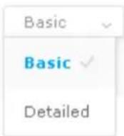 |
| When Mesh Root is selected | Wireless Downlink Band - Choose a wireless band for connecting with a downlink mesh root or a downlink mesh node.Group Name - Display the name of the current mesh group.Auto Reselect - It is selected in default. To perform the auto reselect, make sure the process for CFG Sync and CFG Check for mesh nodes are successful. If enabled, after changing the environment of mesh network (e.g., offline, disconnection), the root device will perform auto reselect to reconstruct the mesh network. |
| When Mesh Node is selected | Wired Uplink - Check the box if such VigorAP connects to an uplink mesh root or an uplink mesh node with an Ethernet cable.Wireless Uplink/Downlink Band - Choose a wireless band for connecting with an uplink/downlink mesh root or an uplink/downlink mesh node. |
| Mesh Group When the VigorAP is set as mesh root or is added to a mesh group, the basic information including role, MAC address, and model name of the AP will be shown in this area.Up to 8 entries (one mesh root and seven mesh nodes) will be shown on this field.Reset - Click it to clear the Mesh Group information.Delete - Click it to remove the selected entry. | |
| Add Mesh Node | Click Search to find out available mesh node on the network.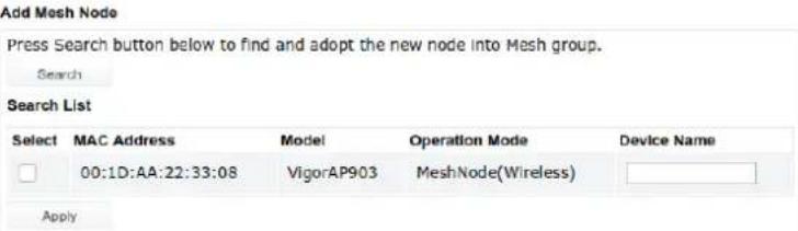 Check the one you want and click Apply. The selected AP will be added onto current mesh root. Check the one you want and click Apply. The selected AP will be added onto current mesh root. |
| Backup Mesh Config Backup - Click the button to save the configuration as a file.Upload/Restore - Click the Upload button to specify a configuration file. Then click Restore to apply the configuration.When the MAC address of such VigorAP does not appear under the mesh group, the restore operation will not succeed and the error message, "Device MAC is not in mesh group list", will be shown instead. | |
How to set up a mesh group?
The following steps will guide you how to setup a Mesh Group (with mesh root and mesh node) from Mesh >> Mesh Setup.
- Open Mesh>>Mesh Setup. Click Mesh Root and click OK for the VigorAP connected to PC with Ethernet cable. At first, a Mesh Group is with only Mesh Root.
Mesh >> Mesh Setup
General Setup
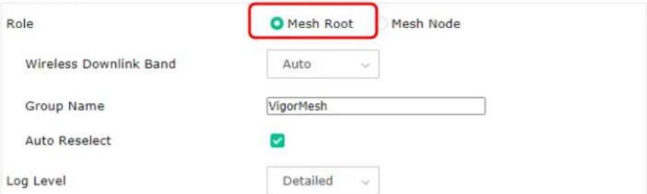
Mesh Group
| Select Index | Role | MAC Address | Model | CFG Sync | CFG Check | Device Name |
| 1 | Root | 00:1D:AA:04:F2:C8 | VigorAP1000C | |||
| Reset |
Add Mesh Node

Backup Mesh Config

- Click the Search button in the field of Add Mesh Node.
Mesh Group
| Select | Index | Role | MAC Address | Model |
| 1 | Root | 00:1D:AA:04:F2:C8 | VigorAP1000C | |
| Reset | ||||
OK
Cancel
Add Mesh Node
Press Search button below to find and adopt the new node into Mesh group.
Search

Backup Mesh Config

- Wait until the searching result appears.
Add Mesh Node
Press Search button below to find and adopt the new node into Mesh group.
Search
Search List
| Select | MAC Address | Model | Operation Mode | Device Name |
| 00:50:7F:F1:7E:EA | VigorAP903 | MeshNode(Wireless) | ||
| 00:1D:AA:04:F0:10 | VigorAP1000C | MeshNode(Wireless) | ||
| 00:1D:AA:32:BC:24 | VigorAP920RPD | MeshNode(Wired) | ||
| 00:1D:AA:78:C9:20 | VigorAP920R | MeshNode(Wireless) | ||
| 00:1D:AA:78:CF:B0 | VigorAP920R | MeshNode(Wireless) | ||
| 00:1D:AA:68:D6:18 | VigorAP920RPD | MeshNode(Wired) | ||
| Apply | ||||
Backup Mesh Config

- Choose the device(s) you want to add to the Mesh Group as mesh node(s) and define the Device Name for each node. In this example, five devices are specified as mesh nodes.
Add Mesh Node
Press Search button below to find and adopt the new node into Mesh group.
Search
Search List
| Select | MAC Address | Model | Operation Mode | Device Name |
 | 00:50:7F:F1:7E:EA | VigorAP903 | MeshNode(Wireless) | room1 |
| 00:1D:AA:04:F0:10 | VigorAP1000C | MeshNode(Wireless) | room2 | |
| 00:1D:AA:32:BC:24 | VigorAP920RPD | MeshNode(Wired) | ||
 | 00:1D:AA:78:C9:20 | VigorAP920R | MeshNode(Wireless) | room3 |
| 00:1D:AA:78:CF:B0 | VigorAP920R | MeshNode(Wireless) | room4 | |
| 00:1D:AA:68:D6:18 | VigorAP920RPD | MeshNode(Wired) | room5 |
Backup Mesh Config
Backup
Upload
Restore
- Click the Apply button and wait for it to finish the procedure.
Add Mesh Node
Press Search button below to find and adopt the new node into Mesh group.
Search
Search List
| Select | MAC Address | Model | Operation Mode | Device Name |
| ✓ | 00:50:7F:F1:7E:EA | VigorAP903 | MeshNode(Wireless) | room1 |
| ✓ | 00:1D:AA:04:F0:10 | VigorAP1000C | MeshNode(Wireless) | room2 |
| □ | 00:1D:AA:32:BC:24 | VigorAP920RPD | MeshNode(Wired) | |
| ✓ | 00:1D:AA:78:C9:20 | VigorAP920R | MeshNode(Wireless) | room3 |
| ✓ | 00:1D:AA:78:CF:B0 | VigorAP920R | MeshNode(Wireless) | room4 |
| ✓ | 00:1D:AA:68:D6:18 | VigorAP920RPD | MeshNode(Wired) | room5 |
| Select | MAC Address | Model | Operation Mode | Device Name |
| ✓ | 00:50:7F:F1:7E:EA | VigorAP903 | MeshNode(Wireless) | room1 |
| ✓ | 00:1D:AA:04:F0:10 | VigorAP1000C | MeshNode(Wireless) | room2 |
| □ | 00:1D:AA:32:BC:24 | VigorAP920RPD | MeshNode(Wired) | |
| ✓ | 00:1D:AA:78:C9:20 | VigorAP920R | MeshNode(Wireless) | room3 |
| ✓ | 00:1D:AA:78:CF:B0 | VigorAP920R | MeshNode(Wireless) | room4 |
| ✓ | 00:1D:AA:68:D6:18 | VigorAP920RPD | MeshNode(Wired) | room5 |
Backup Mesh Config
Backup
Upload
...
Restore
- After finishing the mesh network configuration, refer to Mesh>>Mesh Status for viewing the result. A mesh root with 5 mesh nodes is online.
| Local Status | Refresh | ||
| Device Name | VigorAP 1000C | ||
| MAC Address | DD:1D:AA:04:F2:C8 | ||
| Model | VigorAP 1000C | ||
| Operation Mode | MeshRoot | ||
| Link Status | Connected | ||
| Hop | D | ||
| Downlink Number | 5 | ||
| Downlink | DD:1D:AA:04:F0:10 (VigorAP1000C) | Wireless 5GHz (Ch36) (-38dBm) | |
| DD:1D:AA:78:CF:B0 (VigorAP920R) | Wireless 5GHz (Ch36) (-74dBm) | ||
| DD:1D:AA:58:D6:18 (VigorAP920RPD) | Ethernet | ||
| DD:1D:AA:78:C9:20 (VigorAP920R) | Wireless 5GHz (Ch36) (-54dBm) | ||
| DD:S0:7F:F1:7E:EA (VigorAP003) | Wireless 5GHz (Ch36) (-33dBm) | ||
| Index Status | Device Name | IP Address | MAC Address (Model) | Hop Uplink | Uptime | Clients | |
| 1 | Root | VigorAP1000C | 172.17.3.97 | 00:1D:AA:04:F2:C8(VigorAP1000C) | 0 | 0d01:16:17 | 0 |
| 2 | Online | room1 | 172.17.3.12 | 00:50:7F:F1:7E:EA(VigorAP903) | 1 00:50:7F:F1:7E:ED Wireless5GHz (Ch36) (-30dBm) | 0d00:21:43 | 0 |
| 3 | Online | room2 | 172.17.3.8 | 00:1D:AA:04:F0:10(VigorAP1000C) | 1 00:50:7F:F1:7E:ED Wireless5GHz (Ch36) (-40dBm) | 0d00:44:50 | 0 |
| 4 | Online | room3 | 172.17.3.5 | 00:1D:AA:7B:C9:20(VigorAP920R) | 1 00:50:7F:F1:7E:ED Wireless5GHz (Ch36) (-47dBm) | 0d01:01:45 | 0 |
| 5 | Online | room4 | 172.17.3.98 | 00:1D:AA:7B:CF:B0(VigorAP920R) | 1 00:50:7F:F1:7E:ED Wireless5GHz (Ch36) (-54dBm) | 0d01:02:01 | 0 |
| 6 | Online | room5 | 172.17.3.10 | 00:1D:AA:5B:D5:18(VigorAP920RPD) | 0 00:50:7F:F1:7E:ED Ethernet | 0d01:03:05 | 0 |
II-4-2 Mesh Status
This page shows that one Mesh Group can contain up to 8 devices. In the following figure, the 7th Device with hop 0 is one special Ethernet Backhaul. It means this node will use Ethernet cable to join the mesh group while others use the wireless link.
Mesh >> Mesh Status
| Local Status | |
| Device Name | VigorAP1000C |
| MAC Address | 00:1D:AA:04:F2:C8 |
| Model | VigorAP1000C |
| Operation Mode | MeshRoot |
| Group Name | VigorMesh |
| Link Status | Connected |
| Hop | 0 |
| Downlink Number | 0 |
| Devices | Total number of Clients: 0 | |||||
| Index | Status | Device Name | IP Address | MAC Address(Model) | Hop Uplink Uptime | Clients Speed Test |
| 1 | Root | VigorAP100... | 192.168.1.11 | 00:1D:AA:04:F2:C8(VigorAP1000C) | 00d03:13:02 | 0 |
| ● | Online(sync ready) | ● Online | ● Offline | Last updated: Thu Feb 27 17:08:22 2020 | ||
| Item | Description | |||||||
| Local Status | Display general information for such VigorAP. | |||||||
| Devices Display detailed | information for this VigorAP (as mesh root) and mesh node(s) in the group. Index - Display the number of the device within a mesh group. Status - Display the role of the device within a mesh group. Device Name - Display the name of the device (for identification). IP Address - Display the IP address of the device. MAC Address - Display the MAC address of the device. Hop - Display the level of the devices within a mesh group. "0" means the access point is connected to a device by using Ethernet cable (wired). "1" to "3" means the level of the access point within a mesh group and it connects to other access point via wireless link. Uplink - Display the MAC address of the device that the AP connects to. | |||||||
| Total number of Clients | Display the station list of all mesh devices. Station List of All Devices | |||||||
| Index MAC Address | Hostname | Vendor | SSID | Channel | RSSI | TxRate(Kbps) | RxRate(Kbps) | |
| 1 00:50:7F:0:C9:72 | TA001029 | DrayTek | staffs_4F | 6 | 60%(-63dBm) | 0 | 0 | |
| 2 00:50:7F:0:D1:D | ta002171 | DrayTek | staffs_4F | 6 | 41%(-73dBm) | 0 | 0 | |
| 3 SC:97:F3:D5:F7 | Tze-Pingde... | Apple | staffs_4F | 6 | 100% (-49dBm) | 0 | 0 | |
| 4 40:98:AD:5B:F2:52 | Tyranetki... | Apple | staffs | 6 | 55%(-68dBm) | 0 | 0 | |
| 5 00:50:7F:37:6D:E3 | N/A | DrayTek | staffs_4F | 6 | 52%(-69dBm) | 0 | 0 | |
| 6 00:50:7F:37:67:BE | N/A | DrayTek | staffs_4F | 6 | 55%(-68dBm) | 0 | 0 | |
| 7 30:F7:C5:1D:3D:11 | N/A | Apple | guests | 6 | 83%(-57dBm) | 30 | 12 | |
| 8 40:F0:2F:22:EB:A0 | N/A | LiteonTe | staffs | 6 | 34%(-76dBm) | 22 | 4 | |
| 9 18:05:90:DE:D4:E5 | N/A | Apple | staffs_4F | 6 | 100% (-44dBm) | 0 | 0 | |
| 10 60:45:CB:57:1F:36 | N/A | N/A | staffs_4F | 6 | 15%(-84dBm) | 0 | 0 | |
| 11 AC:5F:3E:62:E6:0D | N/A | Samsung | staffs_4F | 6 | 81%(-58dBm) | 0 | 0 | |
| 12 50:BC:96:E0:00:11 | N/A | Apple | staffs | 6 | 71%(-62dBm) | 0 | 0 | |
| 13 04:B1:67:52:48:90 | RedmiS- mys... | N/A | staffs_4F | 6 | 45%(-72dBm) | 0 | 0 | |
| 14 04:C2:3E:3F:CB:F8 | android-ac... | HTC | staffs_4F | 6 | 55%(-68dBm) | 0 | 0 | |
| 15 GC:8B:FD:31:08:78 | N/A | Intel | staffs_4F | 6 | 89%(-55dBm) | 2 | 2 | |
| 16 SB:48:22:EB:F8:62 | android-5f... | Sony | staffs | 6 | 55%(-68dBm) | 0 | 0 | |
| 17 CC:9F:7A:63:11:27 | N/A | N/A | staffs_4F5... | 36 | 52%(-69dBm) | 0 | 0 | |
| 18 20:47:DA:5B:17:79 | RedmiNote5... | N/A | staffs_4F5... | 36 | 50%(-70dBm) | 0 | 0 | |
| 19 70:81:EB:65:80:E5 | cheng | Apple | staffs_4F5... | 36 | 87%(-56dBm) | 0 | 0 | |
| 20 BC:83:90:64:FF:A4 | N/A | Apple | staffs_4F5... | 36 | 36%(-75dBm) | 0 | 0 | |
II-4-3 Mesh Discovery
Before a Mesh Node is connected, it is unable to check the device status from Mesh Root. This page can help to discover all Mesh devices around and offer the Link Status and Operation Mode of each Mesh device.
Mesh >> Mesh Discovery
Device List
| Index | MAC Address | Model | Operation Mode | Link Status |
| 1 | 00:50:7F:F1:7F:1D | VigorAP903 | MeshNode(Wireless) | Connected |
| 2 | 00:1D:AA:62:0F:E8 | Vigor2862 | MeshRoot | Connected |
| 3 | 00:1D:AA:63:2C:00 | VigorAP920R | MeshRoot | Connected |
| 4 | 00:1D:AA:57:5D:38 | VigorAP1000C | AP | |
| 5 | 00:1D:AA:04:F0:D8 | VigorAP1000C | MeshNode(Wireless) | Connected |
| 6 | 00:1D:AA:04:F0:DC | VigorAP1000C | AP | |
| 7 | 00:1D:AA:04:F0:6C | VigorAP1000C | MeshRoot | Connected |
| 8 | 00:1D:AA:63:2C:10 | VigorAP920RPD | MeshNode(Wireless) | Connected |
| 9 | 00:50:7F:F1:7E:CB | VigorAP903 | MeshRoot | Connected |
Scan
Note: During the scanning process (about 10 seconds), no station is allowed to connect with the AP and Mesh Network may disconnect.
For obtaining the list of devices around this VigorAP, click Scan. Later, surrounding VigorAP device(s) will be displayed on this page.
II-4-4 Basic Config Sync
If you add one Mesh Node in a mesh group, the Mesh Root will send the basic configuration to the device. This page could help you to change the Mesh Root settings and deliver the new configuration of the Mesh Root to all "connected" Mesh Nodes.
Mesh >> Basic Configuration Sync
Select All
□ System Maintenance
| Index | Name | Value |
| 1 | ManagementServer.URL | |
| 2 | ManagementServer.Usage | |
| 3 | ManagementServer.Password | ****** |
| 4 | ManagementServer.ConnectionRequestUsername | vigor |
| 5 | ManagementServer.ConnectionRequestPassword | ****** |
| 6 | ManagementServer.PeriodicInformEnable | 1 |
| 7 | ManagementServer.PeriodicInformInterval | 900 |
| 8 | X_00507F_System.Management.SkipQuickStartWizard | Enable |
| 9 | X_00507F_System.TR069Setting.CPEEnable | 0 |
| 10 | X_00507F_System.SyslogMail.SysLogAccess.SysLogEnable | 0 |
| 11 | X_00507F_System.SyslogMail.SysLogAccess.LogServerIP | |
| 12 | X_00507F_System.SyslogMail.SysLogAccess.LogServerPort | 514 |
| 13 | X_00507F_System.SyslogMail.SysLogAccess.LogLevel | All |
| 14 | X_00507F_System.SyslogMail.MailAlert.MailAlertEnable | 0 |
| 15 | X_00507F_System.SyslogMail.MailAlert.SMTPServer | |
| 16 | X_00507F_System.SyslogMail.MailAlert.MailTo | |
| 17 | X_00507F_System.SyslogMail.MailAlert.MailFrom | |
| 18 | X_00507F_System.SyslogMail.MailAlert.Usage | |
| 19 | X_00507F_System.SyslogMail.MailAlert.Password | ****** |
| 20 | X_00507F_System.SyslogMail.MailAlert.UseTLS | 1 |
| 21 | X_00507F_System.SyslogMail.MailAlert.AdminLoginAlertEn | 1 |
| 22 | X_00507F_System.SyslogMail.MailAlert.SMTPServerPort |
□ Wireless LAN (2.4GHz)
| Index | Name | Value |
| 1 | X_00507F_WirelessLAN_AP.General.EnableWLAN | 1 |
| 2 | X_00507F_WirelessLAN_AP.General.SSID.1.ESSID | DrayTek-04F2C8 |
| 3 | X_00507F_WirelessLAN_AP.General.SSID.1.Enable | 1 |
Available settings are explained as follows:
| Item | Description |
| System Maintenance / Wireless LAN (2.4Hz) / Wireless LAN (5GHz) Wireless LAN (5GHz-2) | Check the item(s) you want to make configuration sync.Apply – Click it to apply the settings configured by such AP to all connected mesh node. Note that this button is available only when such AP is in mesh root mode. |
Tips for Mesh Network Setup
- Set up TWO mesh devices with uplink RSSI larger than -65dBm.
- Upgrade the firmware version of Mesh devices through Mesh link, starting from the mesh device with less hop number. For example, upgrade the firmware from the root, hop1 Mesh Node then hop2 Mesh Node, and so on.
- VigorMesh network supports up to 3 hops of mesh devices. However, it is suggested to connect the mesh group with less than or equals to 2 hops.
For your reference, we make a real mesh environment test and get the following record. (Use VigorAP APP to do internet speed test with different hops mesh node.)
Internet Download Speed (for root and hop1 \~ hop3):
iPad connects to Root : 80Mbps
iPad connects to hop1 Node : 49Mbps (Uplink RSSI : -55dBm)
iPad connects to hop2 Node : 41Mbps (Uplink RSSI : hop2 -64dBm / hop1 -55dBm)
iPad connects to hop3 Node : 26Mbps (Uplink RSSI : hop3 -62dBm / hop2 -68dBm / hop1 -55dBm)
It is not suggested to use a wireless Mesh Node with Ethernet cable connected to a Mesh Root.
• If resetting a Mesh Root,
All "connected" Mesh Nodes will be informed to reset.
- Group List and Group Key will be reset, too.
For those Mesh Nodes unable to reset, reset them manually. Reset the Group List by web or factory default.
- If resetting a Mesh Node,
- Group List and Group Key will be cleared.
- Link Status will become "New".
- Mesh network status also can be viewed and checked through the dashboard by clicking MESH NETWORK.
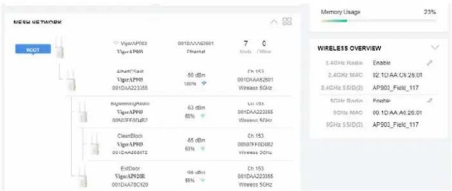
other
| Device | Value | | :--- | :--- | | ViperAP903 | 001DAAA2601 | | Viper AP904 | 001DAA22355 | | Ethernet | -50 dBm | | Ch 153 | 001DAAA62801 | | Wireless 5GHz | | | ViperAP903 | -63 dBm | | 001DAA22355 | 85% | | Ch 153 | 001DAA22355 | | Wireless 5GHz | | | CleanBlock | -65 dBm | | ViperAP903 | 63% | | Ch 153 | 00507FF00NB2 | | Viper AP904 | -96 dBm | | Ch 153 | 001DAA22355 | | 001DAA2807Z | 85% | | Wireless 5GHz | | Memory Usage 23% WIRELESS OVERVIEW 2.4GHz Radio Enable 2.4GHz MAC I2.1U AA C6:26.01 2.4GHz SSID(2) AP903_Field_117 5GHz Radio Enable 5GHz MAC 00.1D-AA-A6:26.01 5GHz SSID(2) AP903_Field_117- If Mesh Search / Apply / Discover is worked too fast or is done with empty result, your request may be rejected. Please try again.
- Troubleshooting:
- Check the firmware version. Please make sure all APs within the mesh group are in the newest firmware version.
- Check the OP (operation) Mode. Make sure new Mesh Node doesn't accidentally get DHCP IP and becomes AP mode.
- Check the country code and channels. For example, it is impossible for connecting a VigorAP 1000C Mesh Root with 5G channel 36 to VigorAP920R Wireless Mesh Node in EU country code.
- Check the channel load. Make sure it is not over 70%.
CHANNEL LOAD
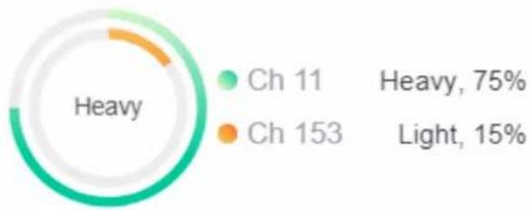
pie
| Category | Value (%) | |---|---| | Heavy | 75 | | Light | 15 |- Collect some Mesh logs and send the result to DrayTek for analyzing.
![DrayTek Syslog 4.5.6 Syslog Utility Log 遮通器 關鍵字: 使用至: AI 172.17.3.6 APNOSR LAN 資訊 傳送封包 9:56 接收封包 47:36 WAN 資訊 WANI WAN IP (固定) -- -- 開運 IP (固定) -- -- APP Mesh 使用者存取紀錄 Channel Foaming Wireless 其他 □ 暫停 系統時間 路由器時間 上核 訊息 2018-11-08 19:01:16 Nov 8:10:58:05 syslog [dwn] dwn_pkt_recv Announce-Keepalive 2018-11-08 19:01:15 Nov 8:10:58:04 syslog [dwn] dwn_pkt_send Alive 2018-11-08 19:01:04 Nov 8:10:57:52 syslog [dwn] dwn_pkt_send Alive 2018-11-08 19:01:01 Nov 8:10:57:50 syslog [dwn] dwn_pkt_recv Announce-Keepalive 2018-11-08 19:00:59 Nov 8:10:57:48 kernel [7525.325564][dwn] Mesh IE Record[Isolate] 00:10:AA/SC A6:C8 2018-11-08 19:00:53 Nov 8:10:57:41 syslog [dwn] dwn_pkt_send Alive 2018-11-08 19:00:47 Nov 8:10:57:36 syslog [dwn] dwn_pkt_recv Announce-Keepalive 2018-11-08 19:00:41 Nov 8:10:57:30 syslog [dwn] dwn_pkt_send Alive 2018-11-08 19:00:39 Nov 8:10:57:28 kernel [7505.200014][dwn] Mesh IE Record[Isolate] 00:10:AA/SC A6:C8 2018-11-08 19:00:33 Nov 8:10:57:22 syslog [dwn] dwn_pkt_recv Announce-Keepalive 2018-11-08 19:00:30 Nov 8:10:57:19 syslog [dwn] dwn_pkt_send Alive 2018-11-08 19:00:19 Nov 8:10:57:08 syslog [dwn] dwn_pkt_send Alive 2018-11-08 19:00:18 Nov 8:10:57:67 syslog [dwn] dwn_pkt_recv Announce-Keepalive 2018-11-08 19:00:07 Nov 8:10:56:56 syslog [dwn] dwn_pkt_send Alive](/content/2026/05/898472/images/a343a1869f57f18c27fcad2f092264d2832fe4ce2c3941b7b126fe665d7a3e6e.jpg)
II-4-5 Advanced Config Sync
If you add one Mesh Node in a mesh group, the Mesh Root will synchronize the advanced configuration to the device based on the setting results on this page.
Mesh >> Advanced Configuration Sync
□ Select All □ Bridge VLAN to Mesh
| Index | Name | Value |
| 1 | X_00507F_LAN.GeneralSetup.BridgeVLANtoWDS | Enable |
Roaming
| Index | Name | Value |
| 1 | X_00507F_WirelessLAN_AP.Roaming.APAClientRoaming.EnMinBasicRate | 0 |
| 2 | X_00507F_WirelessLAN_AP.Roaming.APAClientRoaming.MinBasicRate | 1Mbps |
| 3 | X_00507F_WirelessLAN_AP.Roaming.APAClientRoaming.RSSI | Disable_RSSI_Requirement |
| 4 | X_00507F_WirelessLAN_AP.Roaming.APAClientRoaming.StrictlyRSSISignal | 73 |
| 5 | X_00507F_WirelessLAN_AP.Roaming.APAClientRoaming.MinRSSISignal | 66 |
| 6 | X_00507F_WirelessLAN_AP.Roaming.APAClientRoaming.AdjacentRSSISignal | 5 |
| 7 | X_00507F_WirelessLAN_AP.Roaming.FastRoaming.Enable | 0 |
| 8 | X_00507F_WirelessLAN_AP.Roaming.FastRoaming.CachePeriod | 10 |
| 9 | X_00507F_WirelessLAN_AP.Roaming.FastTransitionRoaming.Enable | 0 |
| 10 | X_00507F_WirelessLAN_AP.Roaming.FastTransitionRoaming.DsOrAir | |
| 11 | X_00507F_WirelessLAN 5G_AP.Roaming.APAClientRoaming.EnMinBasicRate | 0 |
| 12 | X_00507F_WirelessLAN 5G_AP.Roaming.APAClientRoaming.MinBasicRate | 6Mbps |
| 13 | X_00507F_WirelessLAN 5G_AP.Roaming.APAClientRoaming.RSSI | Disable_RSSI_Requirement |
| 14 | X_00507F_WirelessLAN 5G_AP.Roaming.APAClientRoaming.StrictlyRSSISignal | 73 |
| 15 | X_00507F_WirelessLAN 5G_AP.Roaming.APAClientRoaming.MinRSSISignal | 66 |
| 16 | X_00507F_WirelessLAN 5G_AP.Roaming.APAClientRoaming.AdjacentRSSISignal | 5 |
| 17 | X_00507F_WirelessLAN 5G_AP.Roaming.FastRoaming.Enable | 0 |
| 18 | X_00507F_WirelessLAN 5G_AP.Roaming.FastRoaming.CachePeriod | 10 |
| 19 | X_00507F_WirelessLAN 5G_AP.Roaming.FastTransitionRoaming.Enable | 0 |
| 20 | X_00507F_WirelessLAN 5G_AP.Roaming.FastTransitionRoaming.DsOrAir | |
| 21 | X_00507F_WirelessLAN 5G_2_AP.Roaming.APAClientRoaming.EnMinBasicRate | 0 |
| 22 | X_00507F_WirelessLAN 5G_2_AP.Roaming.APAClientRoaming.MinBasicRate | 6Mbps |
II-4-6 Support List
Mesh >> Support List
The following compatibility test lists Draytek AP models supported by this AP Mesh.
| Model | Status | Firmware Version |
| VigorAP 802 | Y | 1.3.4.1 |
| VigorAP 903 | Y | 1.3.7 |
| VigorAP 912C | Y | 1.3.5 |
| VigorAP 920C | Y | 1.3.4 |
| VigorAP 960C | Y | 1.3.9 |
| VigorAP 1000C | Y | 1.3.4 |
| VigorAP 1060C | Y | 1.3.8 |
Y: Tested and is supported.
N: Not supported.
II-4-7 Mesh Syslog
Mesh >> Mesh Syslog
Mesh Log Information
| Feb 23 10:16:51 | VigorAP1000C: [dmn] dmn_pkt_send Announce-Keepalive |
| Feb 23 10:17:03 | VigorAP1000C: [dmn] dmn_pkt_send Announce-Keepalive |
| Feb 23 10:17:03 | VigorAP1000C: [dmn] dmn_pkt_send Declare-Poke |
| Feb 23 10:17:16 | VigorAP1000C: [dmn] dmn_pkt_send Announce-Keepalive |
| Feb 23 10:17:28 | VigorAP1000C: [dmn] dmn_pkt_send Announce-Keepalive |
| Feb 23 10:17:40 | VigorAP1000C: [dmn] dmn_pkt_send Announce-Keepalive |
| Feb 23 10:17:41 | VigorAP1000C: [dmn] dmn_pkt_send Declare-Poke |
| Feb 23 10:17:53 | VigorAP1000C: [dmn] dmn_pkt_send Announce-Keepalive |
| Feb 23 10:18:05 | VigorAP1000C: [dmn] dmn_pkt_send Announce-Keepalive |
| Feb 23 10:18:18 | VigorAP1000C: [dmn] dmn_pkt_send Announce-Keepalive |
| Feb 23 10:18:18 | VigorAP1000C: [dmn] dmn_pkt_send Declare-Poke |
| Feb 23 10:18:30 | VigorAP1000C: [dmn] dmn_pkt_send Announce-Keepalive |
| Feb 23 10:18:42 | VigorAP1000C: [dmn] dmn_pkt_send Announce-Keepalive |
| Feb 23 10:18:55 | VigorAP1000C: [dmn] dmn_pkt_send Announce-Keepalive |
| Feb 23 10:18:55 | VigorAP1000C: [dmn] dmn_pkt_send Declare-Poke |
| Feb 23 10:19:03 | VigorAP1000C: [dmn] Skip 2.4G Mesh Interface check. |
| Feb 23 10:19:03 | VigorAP1000C: [dmn] Skip 5G Mesh Interface check. |
II-5 Universal Repeater Settings for Range Extender Mode
When you choose Range Extender as the operation mode, the Wireless LAN menu items (for 2.4GHz and 5GHz/5GHz-2) will include General Setup, Security, Access Control, WPS, Advanced Setting, AP Discovery, WDS AP Status, Universal Repeater, Bandwidth Management, Airtime Fairness, Station Control, Roaming, Band Steering and Station List.
This section will introduce settings for Universal Repeater only.
For other wireless setting items (e.g., General Setup, Security, WPS, and etc.), please refer to II-3.
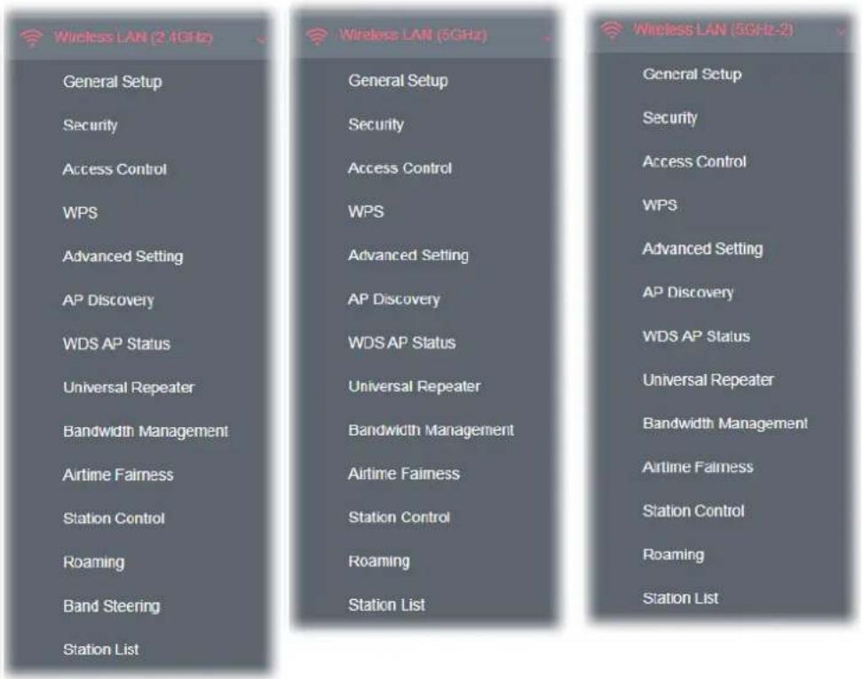
The following figure shows how VigorAP runs as Range Extender:
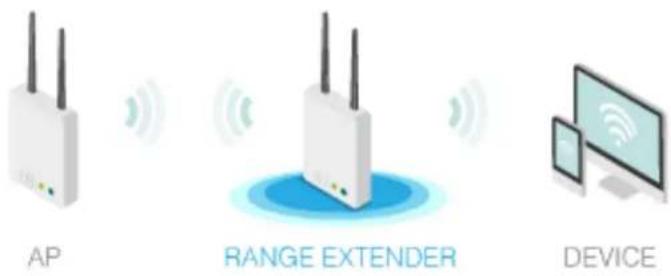
The access point can act as a wireless repeater; it can be Station and AP at the same time. It can use Station function to connect to a root AP and use AP function to serve all wireless stations within its coverage.
Note:
While using Universal Repeater mode, the access point will demodulate the received signal. Please check if this signal is noise for the operating network, then have the signal modulated and amplified again. The output power of this mode is the same as that of AP mode.
Wireless LAN (2.4GHz) >> Universal Repeater
Universal Repeater Parameters
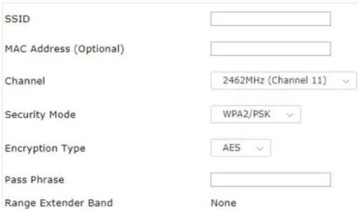
Note: If Channel is modified, the Channel setting of AP would also be changed.
Universal Repeater IP Configuration

Available settings are explained as follows:
| Item | Description |
| Universal Repeater Parameters | |
| SSID Display the SSID defined for Range Extender operation mode in Quick Start Wizard.Change the name of SSID whenever you want. | |
| MAC Address(Optional) | Type the MAC address of access point that VigorAP 1000C wants to connect to. |
| Channel Means the channel of frequency of the wireless LAN.As a tri-band access point, VigorAP offers different channels for WLAN 2.4GHz, 5GHz and 5GHz-2 respectively.You may switch channel if the selected channel is under serious interference. If you have no idea of choosing the frequency, please selectAutoSelectto let system determine for you. | |
Security Mode There are several modes provided for you to choose. Each mode will bring up different parameters (e.g., WEP keys, Pass Phrase) for you to configure.
| Encryption Type for Open/Shared | This option is available when Open/Shared is selected as Security Mode.Choose None to disable the WEP Encryption. Data sent to the AP will not be encrypted. To enable WEP encryption for data transmission, please choose WEP.WEP Keys - Four keys can be entered here, but only one key can be selected at a time. The format of WEP Key is restricted to 5 ASCII characters or 10 hexadecimal values in 64-bit encryption level, or restricted to 13 ASCII characters or 26 hexadecimal values in 128-bit encryption level. The allowed content is the ASCII characters from 33(!) to 126(~) except '#' and ';' |
| Encryption Type for WPA/PSK and WPA2/PSK | This option is available when WPA/PSK or WPA2/PSK is selected as Security Mode.Select TKIP or AES as the algorithm for WPA. |
| Pass Phrase | Type 8~63 ASCII characters, such as 012345678 (or 64 Hexadecimal digits leading by 0x, such as "0x321253abcde..."). |
| Range Extender Band | Display which wireless band (2.4G/5G) is currently used for Universal Repeater.None - No network connection. |
Universal Repeater IP Configuration
| Connection Type Choose DHCP or Static IP as the connection mode. | |
| DHCP – The wireless station will be assigned with an IP from VigorAP. | |
| Static IP – The wireless station shall specify a static IP for connecting to Internet via VigorAP. | |
| Device Name | This setting is available when DHCP is selected as Connection Type. |
| Type a name for the VigorAP as identification. Simply use the default name. | |
| IP Address | This setting is available when Static IP is selected as Connection Type. |
| Type an IP address with the same network segment of the LAN IP setting of VigorAP. Such IP shall be different with any IP address in LAN. | |
| Subnet Mask | This setting is available when Static IP is selected as Connection Type. |
| Type the subnet mask setting which shall be the same as the one configured in LAN for VigorAP. | |
| Default Gateway | This setting is available when Static IP is selected as ConnectionType.Type the gateway setting which shall be the same as the default gateway configured in LAN for VigorAP. |
After finishing this web page configuration, please click OK to save the settings.
Local Area Network (LAN) is a group of subnets regulated and ruled by modem.
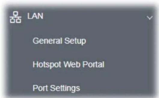
II-6-1 General Setup
Click LAN to open the LAN settings page and choose General Setup.
Note:
Such page will be changed according to the Operation Mode selected. The following screen is obtained by choosing AP as the operation mode.
LAN >> General Setup
Ethernet TCP / IP and DHCP Setup
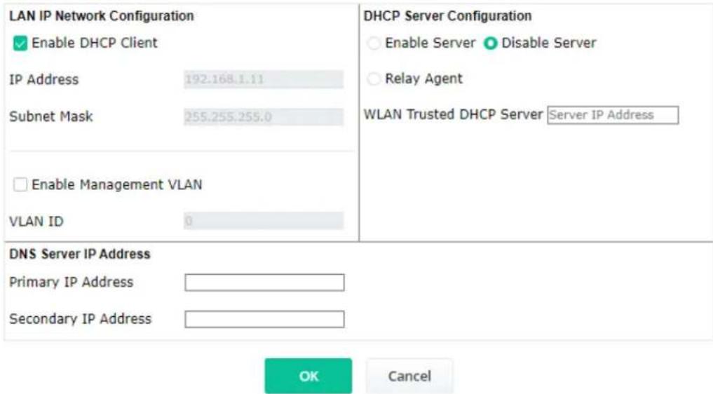
Available settings are explained as follows:
| Item | Description |
| LAN IP Network Configuration | Enable DHCP Client - When it is enabled, VigorAP 1000C will be treated as a client and can be managed / controlled by AP Management server offered by Vigor router (e.g., Vigor2865).IP Address - Enter a private IP address for connecting to a local private network (Default: 192.168.1.2).Subnet Mask - Enter an address code that determines the size of the network. (Default: 255.255.255.0/ 24)Enable Management VLAN - VigorAP 1000C supports tag-based VLAN for wireless clients accessing Vigor device. Only the clients with the specified VLAN ID can access into VigorAP 1000C.VLAN ID - Type the number as VLAN ID tagged on the transmitted packet. "0" means no VALN tag. |
| DHCP Server Configuration | DHCP stands for Dynamic Host Configuration Protocol. DHCP server can automatically dispatch related IP settings to any local user configured as a DHCP client.Enable Server - Enable Server lets the modem assign IP address to every host in the LAN.Start IP Address - Enter a value of the IP address pool for the DHCP server to start with when issuing IP addresses. If the 1st IP address of your modem is 192.168.1.2, the starting IP address must be 192.168.1.3 or greater, but smaller than 192.168.1.254.End IP Address - Enter a value of the IP address pool for the DHCP server to end with when issuing IP addresses.Subnet Mask - Type in an address code that determines the size of the network. (Default: 255.255.255.0/ 24)Default Gateway - Enter a value of the gateway IP address for the DHCP server.Lease Time - It allows you to set the leased time for the specified PC.Primary DNS Server - You must specify a DNS server IP address here because your ISP should provide you with usually more than one DNS Server. If your ISP does not provide it, the modem will automatically apply default DNS Server IP address: 194.109.6.66 to this field.Secondary DNS Server - You can specify secondary DNS server IP address here because your ISP often provides you more than one DNS Server. If your ISP does not provide it, the modem will automatically apply default secondary DNS Server IP address: 194.98.0.1 to this field.Relay Agent - Specify which subnet that DHCP server is located the relay agent should redirect the DHCP request to.DHCP Relay Agent - It is available when Enable Relay Agent is selected. Set the IP address of the DHCP server you are going to use so the Relay Agent can help to forward the DHCP request to the DHCP server.Disable Server - Disable Server lets you manually or use other DHCP server to assign IP address to every host in the LAN.WLAN Trusted DHCP Server –There is no right for such VigorAP to assign IP address for wireless LAN user. However, you can specify another valid DHCP server on other VigorAP to make the wireless LAN client obtaining the IP address from the designated DHCP server.Specify a DHCP server in such field. All the IP addresses of the devices on LAN of VigorAP will be assigned via such specified server. It is used to avoid IP assignment interference due to multiple DHCP servers in one LAN. |
| DNS Server IP Address | Primary DNS Server - You must specify a DNS server IP address here because your ISP should provide you with usually more than one DNS Server. If your ISP does not provide it, the modem will automatically apply default DNS Server IP address: 194.109.6.66 to this field.Secondary DNS Server - You can specify secondary DNS server IP address here because your ISP often provides you more than one DNS Server. If your ISP does not provide it, the modem will automatically apply default secondary DNS Server IP address: 194.98.0.1 to this field. |
After finishing this web page configuration, please click OK to save the settings.
II-6-2 Hotspot Web Portal
This page allows you to configure a profile with specified URL for accessing into or display a message when a wireless/LAN user connects to Internet through this router. No matter what the purpose of the wireless/LAN client is, he/she will be forced into the URL configured here while trying to access into the Internet or the desired web page through this router. That is, a company which wants to have an advertisement for its products to users can specify the URL in this page to reach its goal.
LAN >> Hotspot Web Portal
Hotspot Web Portal Profile:
| Index | Enable | Comments | Login Mode | Applied Interface |
| 1 | None |
Note: AP must connect to the Internet otherwise Web Page redirection won't work.

Available settings are explained as follows:
| Item | Description |
| Index Display the number link which allows you to configure the profile. | |
| Enable Check the box to enable such profile. | |
| Comments Display the content (Disable, URL Redirect or Message) of the profile. | |
| Login Mode | Display the login mode that a client uses to access into Internet. |
| Applied Interface Display the applied interfaces of the profile. | |
Click the index number (e.g., #1 in this case) to open the setting pages.
(1) Hotspot Web Portal Settings
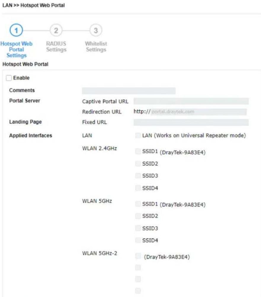
Note: AP must connect to the Internet otherwise Web Page redirection won't work.
Save and Next
Cancel
Available settings are explained as follows:
| Item | Description |
| Enable Check it to enable the hotspot web portal settings. | |
| Comments Enter a brief description for this profile. | |
| Portal Server | Captive Portal URL - Enter the captive portal URL.Redirection URL - Enter the URL to which the client will be redirected. |
| Landing page | Fixed URL - Enter the URL as the landing page for wireless clients. |
| Applied Interfaces | LAN - The current Hotspot Web Portal profile will be in effect for the selected LAN.SSID1 to SSID4 - The current Hotspot Web Portal profile will be in effect for the selected WLAN SSIDs. |
| Next Click to access into next page. | |
After finishing this web page configuration, please click Next for next setting page.
(2) RADIUS Settings
Configure the external RADIUS server for mutual authentication.
LAN >> Hotspot Web Portal
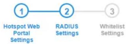
flowchart
graph LR
    A["1 Hotspot Web Portal Settings"] --> B["2 RADIUS Settings"]
    B --> C["3 Whitelist Settings"]
RADIUS Setup
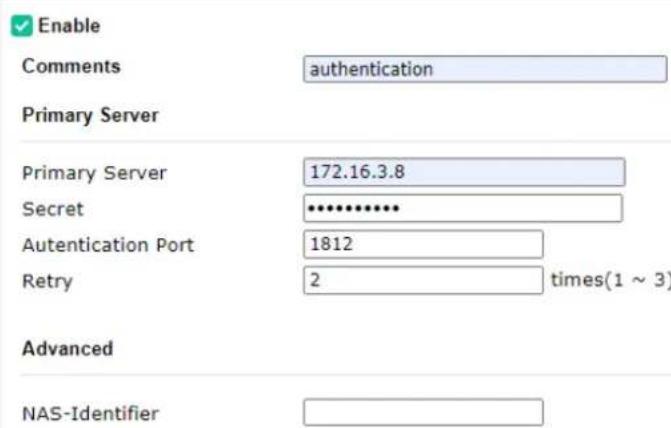
Note: Secret can contain only a-z A-Z 0-9 . < > + = \ | ? @ # \~ ' \$ % & / _ - = [ ] {} ' ^ ! ()
Back
Save and Next
Cancel
Available settings are explained as follows:
| Item | Description |
| Enable Check it to enable the RADIUS server settings. | |
| Comments Enter a brief description for this profile. | |
| Primary Server Enter the IP address of RADIUS server. | |
| Secret The RADIUS server and client share a secret that is used to authenticate the messages sent between them. Both sides must be configured to use the same shared secret. The maximum length of the shared secret you can set is 36 characters. | |
| Authentication Port The UDP port number that the RADIUS server is using. The default value is 1812, based on RFC 2138. | |
| Retry Set the number of attempts to perform reconnection with RADIUS server. | |
| Advanced | NAS-Identifier - Enter an ID. |
| Next Click to access into next page. | |
After finishing this web page configuration, please click Next for next setting page.
(3) Whitelist Settings
Users are allowed to send and receive the traffic that satisfies whitelist settings. IPs under whitelist will not be redirected to other website (URL).
LAN >> Hotspot Web Portal

Hotspot Web Portal Settings
RADIUS Settings
Whitelist Settings
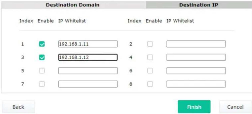
Available settings are explained as follows:
| Item | Description |
| Destination Domain | |
| Enable Check to enable the setting. | |
| Domain Whitelist Enter a domain (URL) / an IP address. | |
| Destination IP | |
| Enable Check to enable the setting. | |
| IP Whitelist LAN users with the IPs set in this page are able to access into Internet without entering other portal. | |
| Finish Click to save the settings. | |
After finishing this web page configuration, please click Finish to complete the configuration.
II-6-3 Port Settings
To avoid wrong connection due to the insertion of unsuitable Ethernet cable, the function of physical LAN ports can be disabled via web configuration.
LAN >> Port Settings
Port Control
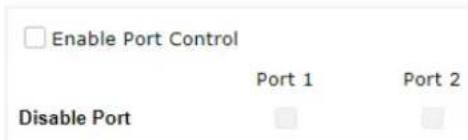
Port/Subnet Mapping
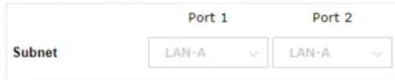
Link Aggregation


Available settings are explained as follows:
| Item | Description |
| Port Control | |
| Enable Port Control | Check it to enable the port control. If it is enabled, you are allowed to disable the function of physical LAN port by checking the corresponding check box. |
| Disable Port Choose and | check the LAN port. |
| Port/Subnet Mapping | |
| Subnet | When Enable 2 Subnet is enabled in Wireless LAN >> General Setup, you can set subnet (LAN-A or LAN-B) for LAN Port 2.In AP mode, if you specify LAN-B for Port 2, wireless clients on LAN-B SSIDs can access Internet through Port 2 independently.However, if you specify LAN-A for Port2, both LAN ports can access LAN-A while wireless clients on LAN-B SSIDs can use local service. |
| Link Aggregation | |
| Enable LACP Enable bonding for Port1 and Port2.With this feature, users can connect Port1 and Port2 to one switch and improve multiple wireless band performance.However, the system performance will drop when LACP(Link Aggregation Control Protocol) is enabled. | |
After finishing this web page configuration, please click OK to save the settings.
This page is left blank.
Chapter III Management

natural_image
Red gear icon enclosed in a partial square frame (no text or symbols)III-1 System Maintenance
For the system setup, there are several items that you have to know the way of configuration: Status, TR-069, Administrator Password, Configuration Backup, Syslog/Mail Alert, Time and Date, SNMP, Management, Reboot System, and Firmware Upgrade.
Below shows the menu items for System Maintenance.
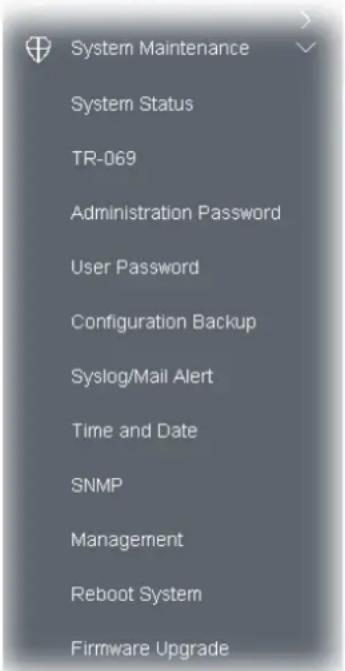
III-1-1 System Status
The System Status provides basic network settings of Vigor modem. It includes LAN and WAN interface information. Also, you could get the current running firmware version or firmware related information from this presentation.
System Status
| Model | : VigorAP1000C |
| Device Name | : VigorAP1000C |
| Firmware Version | : 1.4.6 |
| Build Date/Time | : g1556_2991f48da6 Fri, 24 Feb 2023 14:32:21 |
| System Uptime | : 2d 17:58:03 |
| Operation Mode | : Range Extender |
| System | |
| Memory Total : 236772 kB | |
| Memory Left : 72024 kB | |
| Cached Memory : 23876 kB / 236772 kB | |
| Wireless LAN (2.4GHz) | |
| MAC Address : 00:1D:AA:04:F2:C8 | |
| SSID : DrayTek-04F2C8 | |
| Channel : Auto(5) | |
| Driver Version : 10.4 | |
| Wireless LAN (5GHz) | |
| MAC Address : 00:1D:AA:04:F2:C9 | |
| SSID : DrayTek-04F2C8 | |
| Channel : 36 | |
| Driver Version : 10.4 | |
| Wireless LAN (5GHz-2) | |
| MAC Address : 00:1D:AA:04:F2:CA | |
| SSID : DrayTek-04F2C8 | |
| Channel : Auto(116) | |
| Driver Version : 10.4 |
| LAN | |
| MAC Address | : 00:1D:AA:04:F2:C8 |
| IP Address | : 192.168.1.11 |
| IP Mask | : 255.255.255.0 |
WARNING: Your AP is still set to default password. You should change it via System Maintenance menu.
Each item is explained as follows:
| Item | Description |
| Model /Device Name Display the model name of the modem. | |
| Firmware Version Display the firmware version of the modem. | |
| Build Date/Time Display the date and time of the current firmware build. | |
| System Uptime Display the period that such device connects to Internet. | |
| Operation Mode Display the operation mode that the device used. | |
| System | |
| Memory total Display the total memory of your system. | |
| Memory left Display the remaining memory of your system. | |
| LAN | |
| MAC Address Display the MAC address of the LAN Interface. | |
| IP Address Display the IP address of the LAN interface. | |
| IP Mask Display the subnet mask address of the LAN interface. | |
| Wireless LAN (2.4GHz/5GHz/5GHz-2) | |
| MAC Address Display the MAC address of the WAN Interface. | |
| SSID Display the SSID of the device. | |
| Channel Display the channel that the station used for connecting with such device. | |
This device supports TR-069 standard. It is very convenient for an administrator to manage a TR-069 device (Vigor router, AP and etc.) through VigorACS (Auto Configuration Server).
System Maintenance >> TR-069 Settings
ACS Settings
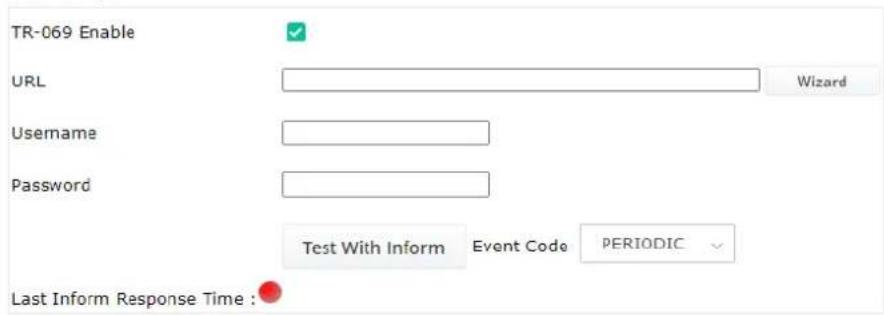
CPE Settings
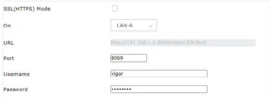
Note: SSL(HTTPS) Mode only works when Vigor ACS SI is 1.1.6 and above version. Please set default gateway, no matter choose LAN-A or LAN-B.
Periodic Inform Settings

STUN Settings
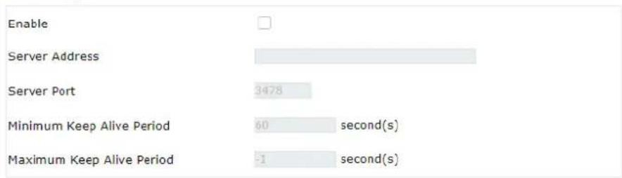
XMPP Settings


Available settings are explained as follows:
| Item | Description |
| ACS Settings | TR-069 Enable - Select to enable TR-069 settings.Wizard - Click it to enter the IP address of VigorACS server host, port number and the handler.URL/Username/Password - Such data must be typed according to the ACS (Auto Configuration Server) you want to link. Please refer to Auto Configuration Server user's manual for detailed information.Test With Inform - Click it to send a message based on the event code selection to test if such CPE is able to communicate with VigorACS SI server.Event Code - Use the drop down menu to specify an event to perform the test.Last Inform Response Time - Display the time that VigorACS server made a response while receiving Inform message from CPE last time. |
| CPE Settings | Such information is useful for Auto Configuration Server (ACS).SSL(HTTPS) Mode - Check the box to allow the CPE client to connect with ACS through SSL.On - Choose the interface (LAN-A or LAN-B) for VigorAP 1000C connecting to ACS server.Port - Sometimes, port conflict might be occurred. To solve such problem, you might change port number for CPE.Usage/Password - Type the username and password that VigorACS can use to access into such CPE. |
| Periodic Inform Settings | The default setting is Enable. Please set interval time or schedule time for the AP to send notification to VigorACS server.Interval Time - Type the value for the interval time setting. The unit is "second". |
| STUN Settings | The default is Disable.If you click Enable, please type the relational settings listed below:Server Address - Type the IP address of the STUN server.Server Port - Type the port number of the STUN server.Minimum Keep Alive Period - If STUN is enabled, the CPE must send binding request to the server for the purpose of maintaining the binding in the Gateway. Please type a number as the minimum period. The default setting is "60 seconds".Maximum Keep Alive Period - If STUN is enabled, the CPE must send binding request to the server for the purpose of maintaining the binding in the Gateway. Please type a number as the maximum period. A value of "-1" indicates that no maximum period is specified. |
| XMPP Settings XMPP is an abbreviation of Extensible Messaging and PresenceProtocol. If your AP register to XMPP server, it could help VigorACS to manage the AP under the NAT at any time, without obstruction. | |
After finishing this web page configuration, please click OK to save the settings.
III-1-3 Administrator Password
This page allows you to set new password for accessing into web user interface of VigorAP.
System Maintenance >> Administration Password
Administrator Settings
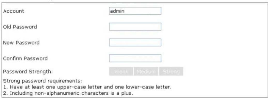
Note : Authorization Account can contain only a-z A-Z 0-9, \~ ` ! @ \% ^ * () _ + = [] | ; < > . ? Authorization Password can contain only a-z A-Z 0-9, \~ ` ! @ # \ % ^ & * () _ + = {} [] | \; < > . ? /

Available settings are explained as follows:
| Item | Description |
| Account Enter the name for accessing into web user Interface. | |
| Old Password Enter the old password for accessing into the web user interface. | |
| New Password Enter in new password in this filed. | |
| Confirm Password Enter the new password again for confirmation. | |
| Password Strength The system will display the password strength (represented with the word of weak, medium or strong) of the password specified above. | |
When you click OK, the login window will appear. Please use the new password to access into the web user interface again.
III-1-4 User Password
This page allows you to set new account and password for accessing the web pages under User Mode.
System Maintenance >> User Password
User Password
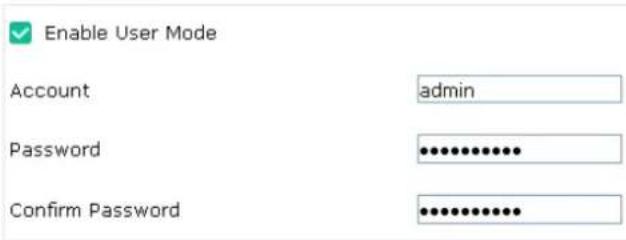
Available settings are explained as follows:
| Item | Description |
| Enable User Mode | After checking this box, you can access into the web user interface with the password typed here for simple web configuration.The settings on simple web user interface will be different with full web user interface accessed by using the administrator password. |
| Account Enter a user name. | |
| Password Enter in new password in this field. The length of the password is limited to 31 characters. | |
| Confirm Password Enter the new password again. | |
Click OK to save the settings.
Settings to be configured in User Mode will be less than settings in Admin Mode. Only basic configuration settings will be available in User Mode.
III-1-5 Configuration Backup
Such function can be used to backup/restore the VigorAP 1000C settings.
System Maintenance >> Configuration Backup
Configuration Backup / Restoration
Restoration
Select a configuration file.
Browse
X
Please enter the password and click Restore to upload the configuration file.
Password (optional):


Note: 1. You will need the same password to do configuration restoration.
- The configuration file from the supported model list would be adopted.
Backup
Please specify a password and click Backup to download current configuration as an encrypted file.

Protect with password
Password

(Max. 23 characters allowed)
Confirm Password

Backup
Note: Password can contain only a-z A-Z 0-9, ! @ \$ % ^ _ - + = {} [] . ? /
Available settings are explained as follows:
| Item | Description |
| Restoration | Browse - Click it to specify a file to be restored.Password (optional) – Enter a password for configuration restoration.Restore – Click it to restore the configuration file to VigorAP. |
| Backup Perform the configuration backup of this device.Protect with password- For the sake of security, the configuration file for the access point can be encrypted.Password – Type several characters as the password for encrypting the configuration file.Confirm Password – Type the password again for confirmation.Backup – Click it to backup the configuration file. | |
Follow the steps below to backup your configuration.
- Go to System Maintenance >> Configuration Backup.
- If required, check the box of Protect with password and enter the password.
- Click Backup to get into the following dialog. The configuration will download automatically to your computer as a file named config.cfg.
The above example is using Windows platform for demonstrating examples. The Mac or Linux platform will appear different windows, but the backup function is still available.
Note:
Backup for Certification must be done independently. The Configuration Backup does not include information of Certificate.
Follow the steps below to restore your configuration.
- Go to System Maintenance >> Configuration Backup.
- Click Upload to choose the correct configuration file for uploading to the AP.
- Click Restore and wait for few seconds.
III-1-6 Syslog/Mail Alert
SysLog function is provided for users to monitor AP. There is no bother to directly get into the Web user interface of the AP or borrow debug equipments.
System Maintenance >> Syslog / Mail Alert Setup
Syslog Access Setup
Enable

Server IP Address

Destination Port
514
Log Level
All

Mail Alert Setup
Enable

SMTP Server

SMTP Server Port

Mail To

Mail From

User Name

Password

SSL

StartTLS

Enable E-Mail Alert:

When Admin Login AP
OK
Cancel
Available settings are explained as follows:
| Item | Description |
| Syslog Access Setup | Enable - Check Enable to activate function of Syslog.Server IP Address -The IP address of the Syslog server.Destination Port -Assign a port for the Syslog protocol. The default setting is 514.Log Level - Specify which level of the severity of the event will be recorded by Syslog. |
| Mail Alert Setup | Enable - Check Enable to activate function of mail alert.SMTP Server - Enter the IP address of the SMTP server.SMTP Server Port - Set the port value for the SMTP server.Mail To - Assign a mail address for sending mails out.Mail From - Assign a path for receiving the mail from outside.User Name - Enter the user name for authentication.Password - Enter the password for authentication.SSL - Check this box to encrypt alert mail. However, if the SMTP server specified here does not support SSL protocol, the alert mail with encrypted data will not be received by the receiver.StartTLS - Check this box to encrypt alert mail. However, if the SMTP server specified here does not support TLS protocol, the alert mail with encrypted data will not be received by the receiver.Enable E-Mail Alert - VigorAP will send an e-mail out when a user accesses into the user interface by using web or telnet.When Admin Login AP - Enable/disable the function. When it is enabled, VigorAP will send out an e-mail to the recipient defined above when a user tries to access into VigorAP by entering login username and password. |
Click OK to save the settings.
III-1-7 Time and Date
It allows you to specify where the time of VigorAP should be inquired from.
System Maintenance >> Time and Date
Time Information
Current System Time
2023 Feb 23 Thu 10:43:40
Inquire Time
status
NTP time synchronized
Time Setting

Enable NTP Client
Time Zone
(GMT+08:00) China Beijing, Chongqing
NTP Server
pool.ntp.org
Use Default
Daylight Saving
NTP synchronization
1 day
OK
Cancel
Available parameters are explained as follows:
| Item | Description |
| Current System Time | Click Inquire Time to get the current time. |
| Enable NTP Client Select to inquire time information from Time Server on the Internet using assigned protocol.Time Zone - Select a time protocol.NTP Server - Type the IP address of the time server.Use Default - Click it to choose the default NTP server.Daylight Saving - Check the box to enable the daylight saving. Such feature is available for certain area.NTP synchronization - Select a time interval for updating from the NTP server. |
| OK Save the settings. |
Click OK to save these settings.
III-1-8 SNMP
This page allows you to configure settings for SNMP and SNMPV3 services.
The SNMPv3 is more secure than SNMP through the authentication method (support e.g., MD5) for the management needs.
System Maintenance >> SNMP
SNMP Agent
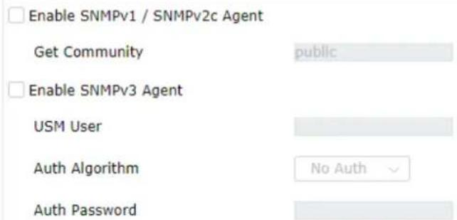
Note: SNMP V1/V2c is read-only and SNMP V3 is read-write.
Available settings are explained as follows:
| Item | Description |
| Enable SNMPv1 / SNMPv2 Agent | Check it to enable this function. |
| Enable SNMPV3 Agent | Check it to enable this function. |
| USM User USM means user-based security mode. | Type a username which will be used for authentication. The maximum length of the text is limited to 23 characters. |
| Auth Algorithm Choose one of the encryption methods listed below as the authentication algorithm. | |
| Auth Password Type a password for authentication. The maximum length of the text is limited to 23 characters. | |
Click OK to save these settings.
III-1-9 Management
This page allows you to specify the port number for HTTP and HTTPS server.
System Maintenance >> Management
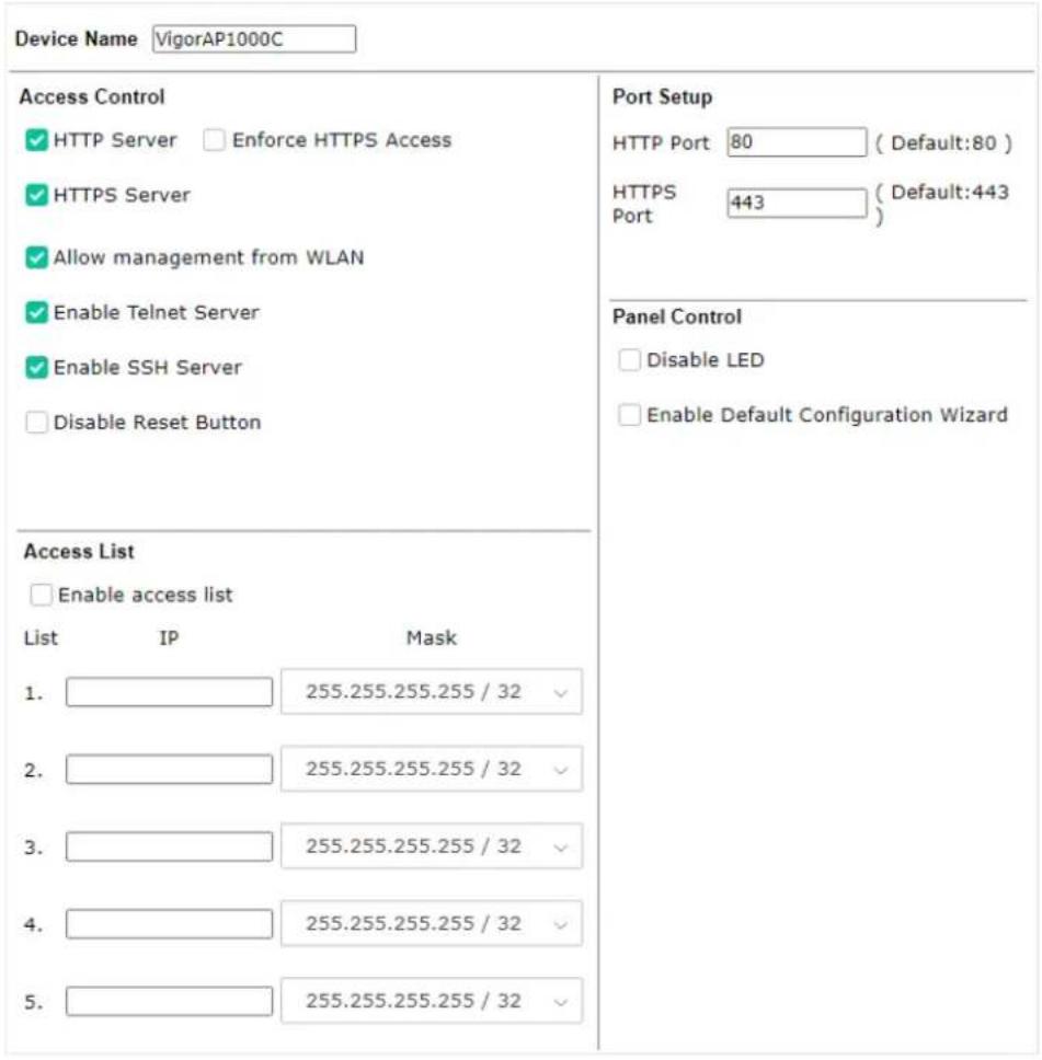
Available parameters are explained as follows:
| Item | Description |
| Device Name The default setting is VigorAP 1000C. Change the name if required. | |
| Access Control | HTTP Server / HTTPS Server - Enable the checkbox to allow system administrators to log in from HTTP or HTTPS server.Enforce HTTPS Access - Enable the checkbox to allow system administrators to log in from HTTPS server only.Allow management from WLAN - Enable the checkbox to allow system administrators to login from wireless LAN.Enable Telnet Server- The administrator / user can access into the command line interface of VigorAP remotely for configuring settings.Disable Reset Button - If enabled, the function of the Reset button will be invalid. |
| Access List | Enable access list - Check the box to specify that the system administrator can only login from a specific host or network defined in the list. A maximum of five IPs/subnet masks is allowed. |
| Port Setup | HTTP port/HTTPS port -Specify user-defined port numbers for the HTTP and HTTPS servers. |
| Panel Control Disable LED | - The LEDs blink always since VigorAP is powered on.Some people might not like that. Therefore the function of LED is allowed to be disabled to make people feeling comfortable and undisturbed. After checking it, all the LEDs on VigorAP will light off immediately after clicking OK.Enable Default Configuration Wizard - Default setting is enabled.When it is enabled, you will be guided into Quick Start Wizard whenever clicking the DrayTek logo on the top of the web user interface.Such function will be disabled if you have configured Operation Mode, WLAN>>General Setup, WLAN>>Bandwidth Management,WLAN>>Station Control or System Maintenance>>Administration Password. |
Click OK to save these settings.
III-1-10 Reboot System
The web user interface may be used to restart your modem. Click Reboot System from System Maintenance to open the following page.
System Maintenance >>Reboot System
Reboot System
Do You want to reboot your AP?
○ Using current configuration
Using factory default configuration
OK
If you want to reboot the modem using the current configuration, check Using current configuration and click OK. To reset the modem settings to default values, check Using factory default configuration and click OK. The modem will take 5 seconds to reboot the system.
Note:
When the system pops up Reboot System web page after configuring the web settings, please click OK to reboot your device for ensuring normal operation and preventing unexpected errors of the modem in the future.
III-1-11 Firmware Upgrade
Before upgrading your modem firmware, you need to install the Modem Tools. The Firmware Upgrade Utility is included in the tools. The following web page will guide you to upgrade firmware by using an example. Note that this example is running over Windows OS (Operating System).
Download the newest firmware from DrayTek's web site or FTP site. The DrayTek web site is www.draytek.com (or local DrayTek's web site) and FTP site is ftp.draytek.com.
Click System Maintenance>> Firmware Upgrade to launch the Firmware Upgrade Utility.
System Maintenance >> Firmware Upgrade
Firmware Upgrade
Select a firmware file.
Browse
ap1000_g1555_b1fc2
Click Upgrade to upload the file.
Upgrade
Firmware Version Status
| Refresh Latest Firmware
Current Firmware Version : 1.4.4
The Latest Firmware Version : 1.4.5
Download
Click Browse to locate the newest firmware from your hard disk and click Upgrade.
System Maintenance >> Firmware Upgrade
Firmware Update
Firmware Upgrade is in progress... It must NOT be interrupted!

Firmware Version Status
Refresh Latest Firmware
Current Firmware Version
The Latest Firmware Version
: N/A
Download
III-2 Central AP Management
Such menu allows you to configure VigorAP device to be managed by Vigor router.
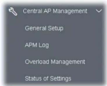
III-2-1 General Setup
Central AP Management >> General Setup
Management by VigorRouter / RootAP

Enable NodeAP

Enable Auto Provision

Enable Check Account Password For Set Group Key
Reset
Root AP MAC:
Manage other VigorAPs

Enable RootAP
Note: LAN-B cannot support APM feature.
RootAP cannot support AP700/AP800/AP900 as Node.
Maximum support 30 APs.

Cancel
Available settings are explained as follows:
| Item | Description |
| Management by VigorRouter/RootAP | |
| Enable NodeAP Check the box to enable the function of AP Management (APM).Enable Auto Provision - VigorAP can be controlled under Central AP Management in the Vigor router. When both the Vigor router series and VigorAP have such feature enabled, once VigorAP is registered to the Vigor router series, theWLAN profilepre-configured on the Vigor router series will be applied to VigorAP immediately. Thus, it is not necessary to configure VigorAP separately.Enable Check Account Password For Set Group Key - If it is | |
| disabled, the RootAP can manage this AP (node AP) without entering the username/password of the node AP.If it is enabled, any RootAP must enter the username/password of this node AP to manage this device. The username/password can be seen on the router'sCentral Management >> AP >> Status page or AP's Central AP Management >> Node Status. An exception is that the RootAP can manage the device directly without entering the username/password of the node AP if the target node AP uses the default username/password (admin/admin). | |
| Manage other VigorAPs | |
| Enable RootAP Check this box to enable AP management. The role of this AP is "Root". | |
Click OK to save these settings.
III-2-2 APM Log
This page will display log information related to wireless stations connected to VigorAP 1000C and central AP management.
Such information also will be delivered to Vigor router (e.g., Vigor2865 or Vigor2927 series) and be shown on Central AP Management>>Event Log of Vigor router.
Central AP Management >> APM Log
| APM Log Information | ||||||
| Clear | Refresh | ☐ | Line wrap | |||
| Aug 24-13:02:54 | syslog: [APM] | Request done. | ||||
| Aug 24-10:47:27 | syslog: [APM] | Get Traffic data. | ||||
| Aug 24-10:47:27 | syslog: [APM] | Request done. | ||||
| Aug 24-10:52:28 | syslog: [APM] | Get Traffic data. | ||||
| Aug 24-10:52:28 | syslog: [APM] | Request done. | ||||
| Aug 24-10:42:26 | syslog: [APM] | Get Traffic data. | ||||
| Aug 24-10:42:26 | syslog: [APM] | Request done. | ||||
| Aug 24-10:47:27 | syslog: [APM] | Get Traffic data. | ||||
| Aug 24-10:47:27 | syslog: [APM] | Request done. | ||||
| Aug 24-10:52:28 | sys log: [APM] | Get Traffic data. | ||||
| Aug 24-10:52:28 | syslog: [APM] | Request done. | ||||
| Aug 24-10:57:29 | syslog: [APM] | Get Traffic data. | ||||
| Aug 24-10:57:29 | syslog: [APM] | Request done. | ||||
| Aug 24-11:02:30 | syslog: [APM] | Get Traffic data. | ||||
| Aug 24-11:02:30 | syslog: [APM] | Request done. | ||||
| Aug 24-11:07:31 | syslog: [APM] | Get Traffic data. | ||||
III-2-3 Overload Management
Load Balance can help to distribute the traffic for all of the access points (e.g., VigorAP 1000C) registered to Vigor router. Thus, the bandwidth will not be occupied by certain access points.
However, traffic overload might be occurred if too many wireless stations connected to VigorAP 1000C for data incoming and outgoing. Therefore, "Force Overload Disassociation" is required to terminate the network connection of the client's station to release network traffic. When the function of "Force Overload Disassociation" in web user interface of Vigor router (e.g., Vigor2860 or Vigor2925 series) is enabled, wireless clients specified in black list of such web page will be disassociated to solve the problem of traffic overload.
The following web page is used to configure white list and black list for wireless stations.
Central AP Management >> Overload Management
Overload Management
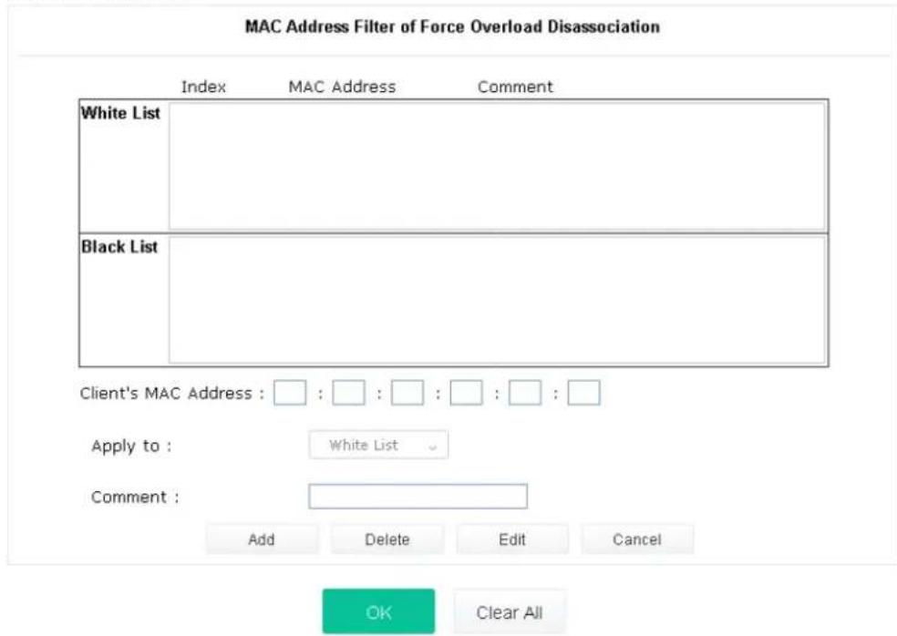
Note: When force overload disassociation is enabled, clients in black list will be disassociated first. Clients in white list will not be disassociated.
Available settings are explained as follows:
| Item | Description |
| White List/Black List | Display the information (such as index number, MAC address and comment) for all of the members in White List/Black List.Wireless stations listed in Black List will be forcefully disconnected first when traffic overload occurs and “Force Overload Disassociation” is enabled. |
| Client’s MAC Address | Specify the MAC Address of the remote/local client. |
| Apply to White List – MAC address listed inside Client’s MAC Address will be categorized as one of members in White List.Black List - MAC address listed inside Client’s MAC Address will be categorized as one of members in Black List. | |
| Comment | Type a brief description for the specified client's MAC address. |
| Add Add a new MAC address into the White List/Black List. | |
| Delete Delete the selected MAC address in the White List/Black List. | |
| Edit Edit the selected MAC address in the White List/Black List. | |
| Cancel Give up the configuration. | |
Click OK to save these settings.
III-2-4 Status of Settings
Load Balance can help to distribute the traffic for all of the access points (e.g., VigorAP 1000C) registered to Vigor2865 or Vigor2927 series. This web page displays the settings related to Load Balance for VigorAP 1000C. In which, Station Number Threshold, Traffic Threshold and Force Overload Disassociation indicate settings configured in Vigor2865 or Vigor2927 series.
Central AP Management >> Status of Settings
| Function Name | Status | Value |
| Load Balance | ||
| Station Number Threshold | × | |
| Max WLAN(2.4GHz) Station Number | 128 | |
| Max WLAN(5GHz) Station Number | 128 | |
| Max WLAN(5GHz-2) Station Number | 128 | |
| Traffic Threshold | × | |
| Upload Limit | None bps | |
| Download Limit | None bps | |
| Force Overload Disassociation | × | |
| Disassociate By | None | |
| RSSI Threshold | -50 dBm | |
"X" means the function is not enabled or VigorAP 1000C has not registered to any Vigor router yet. Below shows a setting example for Load Balance settings configured in Vigor2865 or Vigor2927 series.
AP Load Balance
By Station Number or Traffic
Station Number Threshold
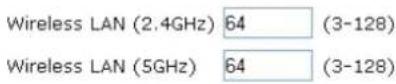
Traffic Threshold

Action When Threshold Exceeded

III-3 Mobile Device Management
Such feature can control / manage the mobile devices accessing the wireless network of VigorAP. VigorAP offers wireless LAN service for mobile device(s), PC users, MAC users or other users according to the policy selected.
Below shows the menu items for Mobile Device Management (MDM).
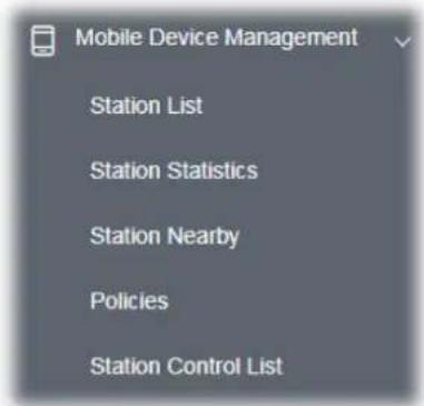
III-3-1 Station List
Station List provides the information related to the number of clients connecting to VigorAP, used bandwidth and the statistics of the AP device OS. Besides, users can create access control policies, device objects and set black & white list for
III-3-1-1 Connected Number
This page lists the graph for the number of wireless stations connected to this Access Point with different time phases.
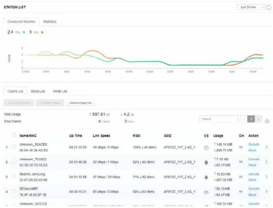
line
| Name/MAC | Up Time | Link Speed | RSSI | SSID | OS | Usage | CH | Action | | --- | --- | --- | --- | --- | --- | --- | --- | --- | | Unknown_52ACE5 10:3A-4D:52:AC:ES | 5d 21:10:59 | 10 Mbps / 5 Mbps | 100% (-45 dbm) | AP912C_117_2.4G_1 | ? | ↑148.14 MB ↓299.73 MB | 11 | DeAuth Block > | | Unknown_72CGE2 0C:9D:92:72:06:E2 | 0d 01:48:06 | 50 Mbps / 1 Mbps | 62% (-65 dbm) | AP912C_117_2.4G_1 | ◆ | ↑7.15 MB ↓60.17 MB | 11 | DeAuth Block > | | Redmit_JerryLing 10:47:DA:25:A5:6B | 0d 01:10:58 | 47 Mbps / 25 Mbps | 71% (-62 dbm) | AP912C_117_2.4G_1 | ◆ | ↑12.83 MB ↓287.36 MB | 11 | DeAuth Block > | | RD3de-MBP 78:4F:43:53:2F' 1E | 0d 00:10:21 | 65 Mbps / 5 Mbps | 68% (-63 dbm) | AP912C_117_2.4G_1 | IOS | ↑50.13 KB ↓54.47 KB | 11 | DeAuth Block > | | Unknown_347CC8 | 0d 00:00:00 | 60 Mbps / 5 Mbps | 60% (-63 dbm) | AP912C_117_2.4G_1 | ◆ | ↑182.55 MB ↓54.47 KB | 11 | DeAuth Block > |III-3-1-2 Statistics
The number of detected devices and the number of device(s) passed/blocked according to the policy specified in Mobile Device Management>>Policies can be illustrated as doughnut chart.
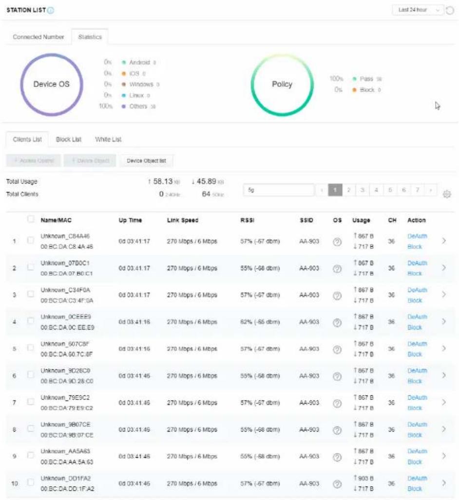
other
| Device | Usage | Speed | Security Status | | :--- | :--- | :--- | :--- | | Unknown_C84A46 00.BC.DA.C8.4A.48 | 57% (-67 dbm) | AA-903 | ? | | Unknown_07B0C1 00.BC.DA.07.B0.C1 | 55% (-68 dbm) | AA-903 | ? | | Unknown_C34F0A 00.BC.DA.C3.4F.0A | 57% (-67 dbm) | AA-903 | ? | | Unknown_0CEEE9 00.BC.DA.0C.EE.E9 | 62% (-66 dbm) | AA-903 | ? | | Unknown_607C8F 00.BC.DA.60.7C.8F | 57% (-67 dbm) | AA-903 | ? | | Unknown_9D2BC9 00.BC.DA.9D.28.CO | 55% (-68 dbm) | AA-903 | ? | | Unknown_79E9C2 00.BC.DA.79.E9/C2 | 57% (-67 dbm) | AA-903 | ? | | Unknown_9B07CE 00.BC.DA.9B.07.CE | 55% (-68 dbm) | AA-903 | ? | | Unknown_AA5A63 00.BC.DA.AA.5A.63 | 55% (-68 dbm) | AA-903 | ? | | Unknown_DD1FA2 00.BC.DA.DD.1F.A2 | 57% (-67 dbm) | AA-903 | ? | | Total Usage ↑58.13 KB ↓45.89 KB Total Clients 0 ≥40Hz 64 ≤0Hz 5g 1 2 3 4 5 6 7 >III-3-1-3 Clients List
The client list displays all the stations connecting to VigorAP.
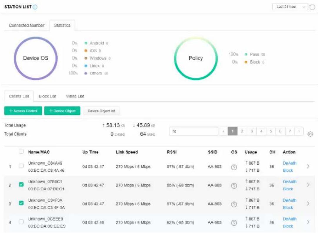
Available settings are explained as follows:
| Item | Description |
| +Access Control | It is available after choosing one of the entries (clients) on Clients List. |
| |
| Wireless LAN - Specify the bandwidth for the access control list. SSID Policy - Set the policy for each SSID as black list or white list or disable. From to list - Display the clients available for applying this accesscontrol.Apply to SSID - Check All to make the device apply the policies to all SSIDs. Or select the one(s) to make the device apply the policies to the selected SSIDs.Close - Exit this page without saving any changes.Save changes - Save the changes and exit this page. | |
| +Device Object To add a device to device object list, choose one of the entries (clients) on Clients List to enable the Device Object button. Click the button to open the following page. | 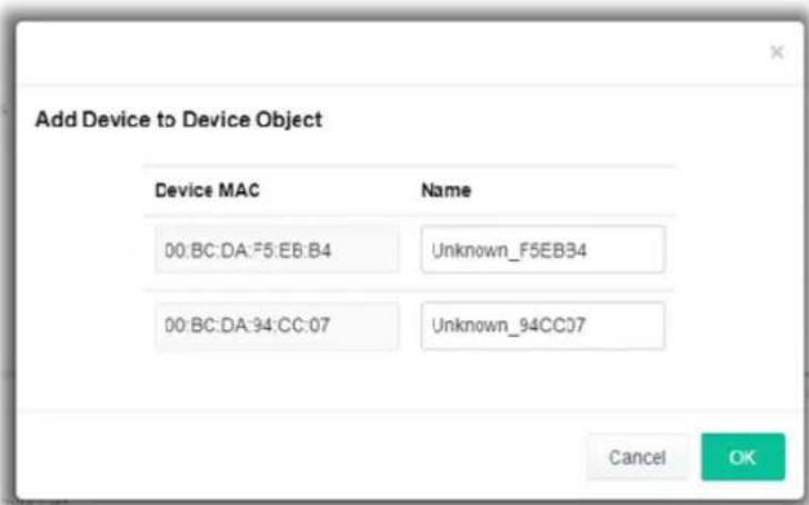 Check the information listed on the page. Change the MAC address or name of the selected entry if required. Then click OK and exit the page. Check the information listed on the page. Change the MAC address or name of the selected entry if required. Then click OK and exit the page. |
| Device Object list The existed device object profiles will be shown on the following page. | 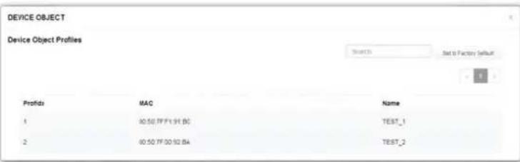 |
| Clients List Display the stations connecting to this Vigor device. | Total Usage - DisplayTotal Clients - Display the number of the clients using 2.4GHzName / MAC - Display the host name / MAC address of the connecting client.Up Time - Display the connection time.Link Speed- Display the link speed.RSSI - Display the RSSI value.SSID - Display the SSID the client used for connecting VigorAP.OS - Display the OS of the client.Usage - Display the bandwidth usage (up and down) of the client.CH - Display the channel used by the client.Action - Display the authentication method used by the client, and if it is on block list or white list. |
II-3-13-4 Block List
This page displays information of the stations under block list.
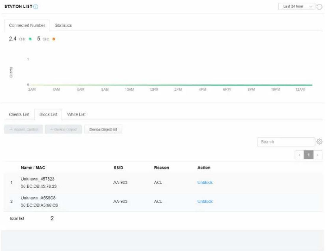
Available settings are explained as follows:
| Item | Description |
| Device Object list Click it to open the Device Object List dialog for reference. | 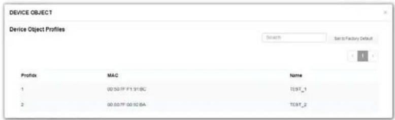 |
| Name / MAC | Display the host name / MAC Address for the connecting client. |
| SSID Display the SSID that the wireless client connects to. | |
| Reason Display the reference information. | |
| Action | Display the action that you can execute for the station.Unblock - Click to unblock the entry. |
III-3-1-5 White List
This page displays general information of the stations under white list.
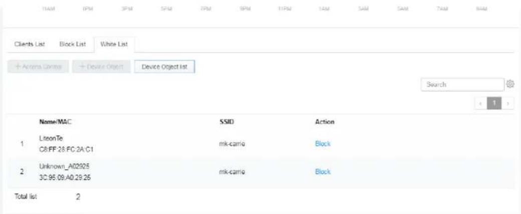
Available settings are explained as follows:
| Item | Description |
| Device Object list Click it to open the Device Object List dialog for reference. | |
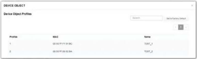 | |
| Name / MAC | Display the host name / MAC Address for the connecting client. |
| SSID Display the SSID that the wireless client connects to. | |
| Action | Display the action that you can execute for the station.Block - Click to block the entry. |
III-3-2 Station Statistics
This page is used for debug or for the user to observe network traffic and network quality.
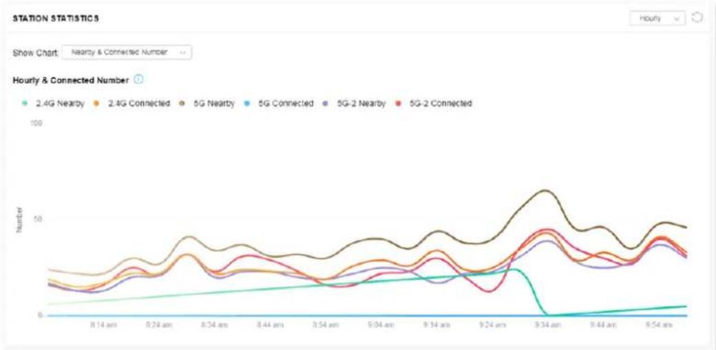
line
| Time | 2.4G Nearby | 2.4G Connected | 5G Nearby | 5G Connected | 5G-2 Nearby | 5G-2 Connected | | -------- | ----------- | -------------- | --------- | ------------ | ----------- | -------------- | | 8:14 am | ~10 | ~15 | ~20 | ~10 | ~15 | ~20 | | 8:24 am | ~15 | ~20 | ~30 | ~15 | ~20 | ~25 | | 8:34 am | ~20 | ~25 | ~40 | ~20 | ~25 | ~30 | | 8:44 am | ~25 | ~30 | ~35 | ~25 | ~30 | ~35 | | 9:04 am | ~30 | ~35 | ~40 | ~30 | ~35 | ~40 | | 9:14 am | ~35 | ~40 | ~45 | ~35 | ~40 | ~45 | | 9:24 am | ~40 | ~45 | ~50 | ~40 | ~45 | ~50 | | 9:34 am | ~50 | ~60 | ~65 | ~50 | ~55 | ~60 | | 9:44 am | ~40 | ~50 | ~55 | ~45 | ~50 | ~55 | | 9:54 am | ~30 | ~40 | ~45 | ~35 | ~40 | ~45 |Available parameters are explained as follows:
| Item | Description |
| Show Chart Choose one of the items to display the statistics chart for wireless stations. | |
| Nearby & Connected NumberNearby & Connected NumberVisiting & Passing NumberVisiting Time | |
| Nearby & Connected Number – Choose it to have the statistics of the wireless stations which is nearby and connected to VigorAP 1000C.Visiting & Passing Number – Choose it to have the statistics of the wireless stations which is visiting and passing to VigorAP 1000C.Visiting Time - Choose it to have the statistics of the wireless stations which is visiting VigorAP 1000C. | |
III-3-3 Station Nearby
This page displays the general information for the nearby stations.
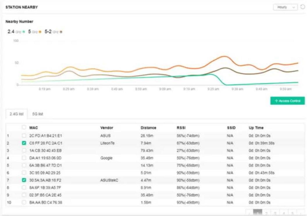
line
| MAC | Vendor | Distance | RSSI | SSID | Up Time | | --- | --- | --- | --- | --- | --- | | 2C:FD:A1:B4:21:E1 | ASUS | 28.18m | 56%(-74dbm) | N/A | 0d: 0h:0m:0s | | C8:FF:28:FC:2A:C1 |LiteonTe | 7.94m | 87%(-63dbm) | N/A | 0d: 0h:39m:38s | | 1A:CB:30:40:43:EB | Google | 79.43m | 27%(-83dbm) | N/A | 0d: 0h:0m:0s | | DA:A1:19:63:06:0D | Google | 35.48m | 50%(-76dbm) | N/A | 0d: 0h:0m:0s | | 6A:3B:B6:47:7D:D1 | ASUSStekC | 14.13m | 75%(-68dbm) | N/A | 0d: 0h:0m:0s | | 3C:95:09:A0:29:25 | ASUSStekC | 5.01m | 90%(-59dbm) | N/A | 0d: 0h:43m:58s | | 30:5A:3A:AB:16:F2 | ASUSStekC | 4.47m | 90%(-58dbm) | N/A | 0d: 0h:0m:0s | | 8A:6F:1B:39:A5:7F | ASUSStekC | 8.91m | 86%(-64dbm) | N/A | 0d: 0h:0m:0s | | 02:3F:B5:CA:2E:45 | ASUSStekC | 35.48m | 50%(-76dbm) | N/A | 0d: 0h:0m:0s | | BA:AA:B0:C4:76:38 | ASUSStekC | 1.58m | 93%(-49dbm) | N/A | 0d: 0h:0m:0s |You can select the station(s) and click +Access Control to configure the nearby stations as the one(s) to pass through VigorAP or to be blocked by VigorAP.
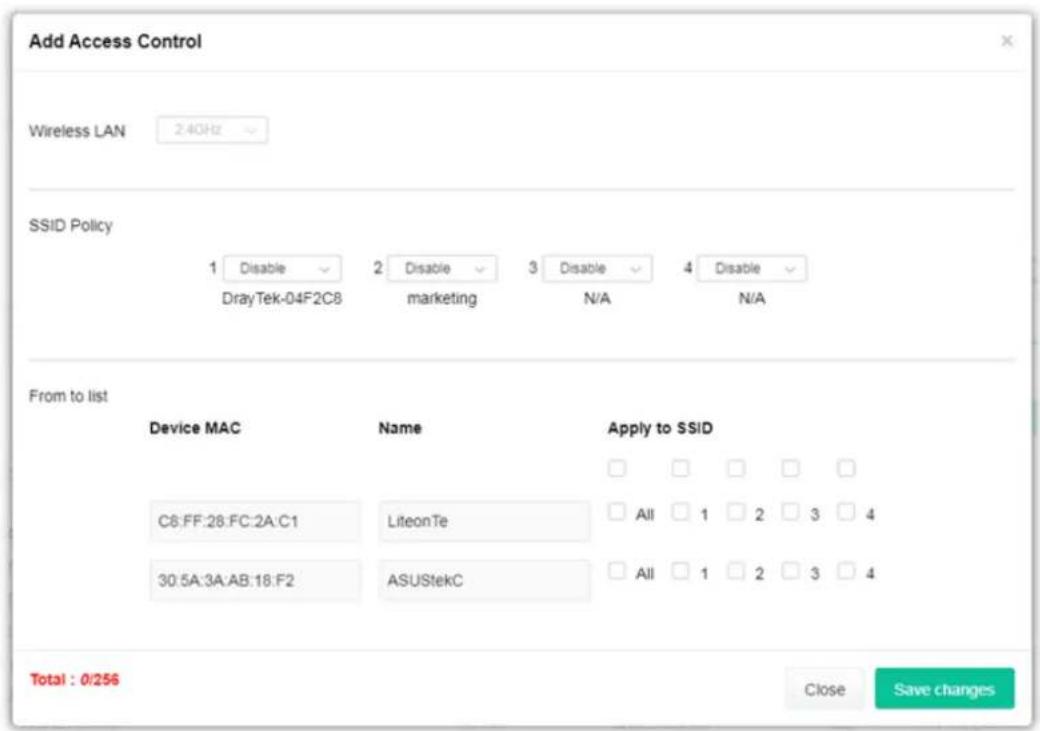
Available parameters are explained as follows:
| Item | Description |
| SSID Policy Determine the policy (disable, white list or black list) applied for the SSID (1 to 4). | |
| From to list Device MAC | - Display the MAC address of the selected station. |
| Name - Display the name of the selected station. | |
| Apply to SSID - Check the box(es) to apply the SSID to the selected station. | |
| Close - Exit the dialog without saving the changes. | |
| Save changes - Save the changes and exit the dialog. | |
III-3-4 Policies
Such page determines which devices (mobile, PC, MAC or others) allowed to make network connections via VigorAP or blocked by VigorAP.
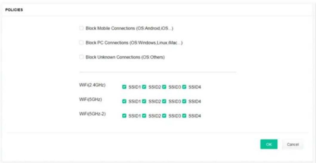
Each item is explained as follows:
| Item | Description |
| Block Mobile Connections | All of mobile devices will be blocked and not allowed to access into Internet via VigorAP. |
| Block PC Connections | All of network connections based on PC, MAC or Linux platform will be blocked and terminated. |
| Block Unknown Connections | Only the unknown network connections (unable to be recognized by Vigor router) will be blocked and terminated. |
| WiFi(2.4GHz) Specify the SSID(s) to apply such policy. | |
| WiFi(5GHz) Specify the SSID(s) to apply such policy. | |
| WiFi(5GHz-2) Specify the SSID(s) to apply such policy. | |
After finished the policy selection, click OK. VigorAP will reboot to activate the new policy automatically.
III-3-5 Station Control List
This page displays information related to the wireless stations connecting to the Vigor AP.
STATION CONTROL LIST
| SSID | MAC | Connection Time | Reconnection Time | |
| 1 | AP912C_117_2.4G_1 | 28:3A:4D:52:AC:E5 | 0d 00:58:50 | 0d 00:00:00 |
| 2 | AP912C_117_2.4G_1 | 20:47:DA:25:A5:6B | 0d 00:48:22 | 0d 00:00:00 |
| 3 | AP912C_117_5G_1 | 40:4E:36:5E:3F:A7 | 0d 00:59:55 | 0d 00:00:00 |
| 4 | AP912C_117_5G_1 | D0:37:45:34:7C:C8 | 0d 00:56:02 | 0d 00:00:00 |
① This page is available when Station Control is enabled.
This page is left blank.
Chapter IV Others

natural_image
Pure electrical circuit lines without any symbolsIV-1 RADIUS Setting
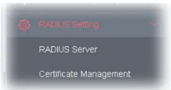
IV-1-1 RADIUS Server
VigorAP 1000C offers a built-in RADIUS server to authenticate the wireless client that tries to connect to VigorAP 1000C. The AP can accept the wireless connection authentication requested by wireless clients.
RADIUS Setting >> RADIUS Server Configuration
Enable RADIUS Server
Authentication Type

Users Profile (up to 256 users)
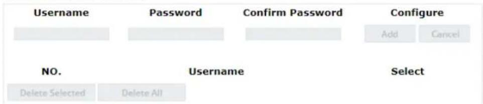
Authentication Client (up to 16 clients)
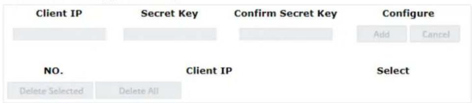
flowchart
graph TD
    A["Client IP"] --> B["Secret Key"]
    B --> C["Confirm Secret Key"]
    C --> D["Configure"]
    E["NO."] --> F["Client IP"]
    F --> G["Select"]
    H["Delete Selected"] --> I["Delete All"]
    I --> F
    J["Add"] --> K["Cancel"]


Available settings are explained as follows:
| Item | Description |
| Enable RADIUS Server | Check it to enable the internal RADIUS server. |
| Authentication Type | Let the user to choose the authentication method for RADIUS server.Radius EAP Type- There are two types, PEAP and EAP TLS, offered for selection. If EAP TLS is selected, a certificate must be installed or must be ensured to be trusted. |
| Users Profile | Username- Type a new name for the user profile.Password- Type a new password for such new user profile.Confirm Password- Retype the password to confirm it.ConfigureAdd- Make a new user profile with the name and password specified on the left boxes.Cancel- Clear current settings for user profile.Delete Selected- Delete the selected user profile (s).Delete All- Delete all of the user profiles. |
| Authentication Client | This internal RADIUS server of VigorAP 1000C can be treated as the external RADIUS server for other users. Specify the client IP and secret key to make the wireless client choosing VigorAP 1000C as its external RADIUS server.Client IP- Type the IP address for the user to be authenticated by VigorAP 1000C when the user tries to use VigorAP 1000C as the external RADIUS server.Secret Key- Type the password for the user to be authenticated by VigorAP 1000C while the user tries to use VigorAP 1000C as the external RADIUS server.Confirm Secret Key- Type the password again for confirmation.ConfigureAdd- Make a new client with IP and secret key specified on the left boxes.Cancel- Clear current settings for the client.Delete Selected- Delete the selected client(s).Delete All- Delete all of the clients. |
| Backup Radius Cfg | Backup- Click to store the configuration set on this page as a file. |
| Upload From File | Browse- Click to upload the RADIUS configuration file from the host to VigorAP.Restore- Click to restore the RADIUS configuration file to VigorAP. |
After finishing this web page configuration, please click OK to save the settings.
IV-1-2 Certificate Management
When the local client and remote server are required to make certificate authentication (e.g., Radius EAP-TLS authentication) for wireless connection and avoiding the attack of MITM, a trusted root certificate authority (Root CA) will be used to authenticate the digital certificates offered by both ends.
However, the procedure of applying digital certificate from a trusted root certificate authority is complicated and time-consuming. Therefore, Vigor AP offers a mechanism which allows you to
generate root CA to save time and provide convenience for general user. Later, such root CA generated by DrayTek server can perform the issuing of local certificate.
Root CA can be deleted but not edited. If you want to modify the settings for a Root CA, please delete the one and create another one by clicking Create Root CA.
RADIUS Setting >> X509 Trusted CA Certificate Configuration
| Name | Subject | Status | Modify |
| Root CA | --- | --- | Create Root CA |
Note: 1. Please setup the "System Maintenance >> Time and Date" correctly before you try to generate a RootCA.
2. The Time Zone MUST be setup correctly.
Click Create Root CA to open the following page. Type or choose all the information that the window request such as subject name, key type, key size and so on.
RADIUS Setting >> Create Root CA
| Certificate Name | Root CA |
| Subject Name | |
| Country (C) | |
| State (S) | |
| Location (L) | |
| Organization (O) | |
| Organization Unit (OU) | |
| Common Name (CN) | |
| Email (E) | |
| Key Type | RSA |
| Key Size | 1024 Bit |
| Apply to Web HTTPS |
Available settings are explained as follows:
| Item | Description |
| Subject Name | Type the required information for creating a root CA.Country (C) – Type the country code (two characters) in this box.State (S)/ Location (L)/ Organization (O)/ Organization Unit (OU)/Common Name (CN) - Type the name or information for the root CA with length less than 32 characters.Email (E) – Type the email address for the root CA with length less than 32 characters. |
| Key Type At present, only RSA (an encryption algorithm) is supported by such device. | |
| Key Size To determine the size of a key to be authenticated, use the drop down list to specify the one you need. | |
| Apply to Web HTTPS | VigorAP needs a certificate to access into Internet via Web HTTPS.Check this box to use the user-defined root CA certificate which will substitute for the original certificate applied by web HTTPS. |
Note:
"Common Name" must be configured with rotuer's WAN IP or domain name.
After finishing this web page configuration, please click OK to save the settings. A new root CA will be generated.
IV-2 Applications
Below shows the menu items for Applications.
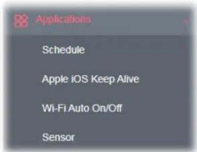
IV-2-1 Schedule
The VigorAP has a built-in clock which can update itself manually or automatically by means of Network Time Protocols (NTP). As a result, you can not only schedule the AP to dialup to the Internet at a specified time, but also restrict Internet access to certain hours so that users can connect to the Internet only during certain hours, say, business hours. The schedule is also applicable to other functions.
You have to set your time before set schedule. In System Maintenance>> Time and Date menu, press Inquire Time button to set the VigorAP's clock to current time of your PC. The clock will reset once if you power down or reset the AP. There is another way to set up time. You can inquiry an NTP server (a time server) on the Internet to synchronize the AP's clock. This method can only be applied when the WAN connection has been built up.
Applications >> Schedule

Available settings are explained as follows:
| Item | Description |
| Current System Time Display current system time. | |
| System time set Click it to open Time and Date page for configuring the time setting. | |
| Set to Factory Default | Click it to return to the factory default setting and remove all the schedule profiles. |
| Index Display the sort number of the schedule profile. | |
| Enable Check it to enable the function of schedule configuration. | |
| Name Display the name of the schedule. | |
| Action Display the action adopted by the schedule profile. | |
| Time Display the time setting of the schedule. | |
You can set up to 15 schedules. To add a schedule:
- Check the box of Enable Schedule.
- Click the Add button to open the following web page.
Applications >> Schedule
Add Schedule
Enable
Name
Start Date
Start Time
Duration Time
End Time
Action
WiFi(2.4GHz)
WiFi(5GHz)
WiFi(5GHz-2)
How Often
Weekday
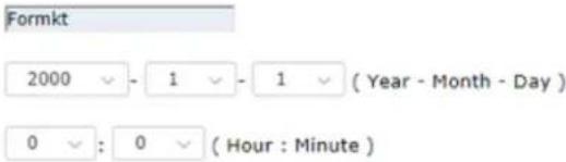


Auto Reboot
Radio
Radio
Radio
Once
Monday
Sunday
SSID2
SSID2
SSID2
Tuesday
。
SSID3
SSID3
SSID3
Wednesday
[Non-Text]
Thursday
[Non-Text]
Friday
[Non-Text]
Saturday
Note: 1. If we set WiFi schedule "Start Time" and "End Time" at exact same time, AP will execute the schedule without an end time.
- "Internet Pause" will add Mac into ACL, so please make sure ACL isn't full before applying schedule. If ACL policy is "Disable", AP will change it to "Blocked".
OK
Cancel
Available settings are explained as follows:
| Item | Description |
| Enable Check to enable such schedule profile. | |
| Name Enter the name of the schedule profile. | |
| Start Date Specify the starting date of the schedule. | |
| Start Time Specify the starting time of the schedule. | |
| Duration Time Specify the duration (or period) for the schedule.It is available only for the action set with WIFI UP, WIFI Down, or Internet Pause. | |
| End Time Display the ending time (sum of start time and duration time) of the schedule. | |
| Action Specify which action should apply the schedule. | |
| Auto RebootAuto RebootWi-Fi UPWi-Fi DOWNLED DISABLELED ENABLESound BuzzerInternet PauseIn which, you have to specify the device object/device group profile for blocking certain wireless clients when Internet Pause is selected as the Action. | |
| WiFi(2.4GHz)/WiFi(5GHz)/WiFi(5GHz-2) | When Wi-Fi UP or Wi-Fi DOWN is selected as Action, you can check the Radio or SSID 2~4 boxes (2.4GHz, 5GHz and 5GHz-2 respectively) to setup the network based on the schedule profile.Note: When Radio is selected, SSID2, SSID3 and SSID4 are not available for choosing, vice versa. Moreover, SSID2, SSID3, and SSID4 are not available for choosing if they are not enabled. |
| How Often Specify how often the schedule will be applied.Once -The schedule will be applied just onceWeekdays -Specify which days in one week should perform the schedule. | |
| Weekday | Choose and check the day to perform the schedule. It is available when Weekdays is selected as How Often. |
- After finishing this web page configuration, please click OK to save the settings. A new schedule profile has been created and displayed on the screen.
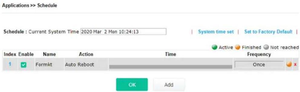
IV-2-2 Apple iOS Keep Alive
To keep the wireless connection (via Wi-Fi) on iOS device in alive, VigorAP 1000C will send the UDP packets with 5353 port to the specific IP every five seconds.
Applications >> Apple iOS Keep Alive
Enable Apple iOS Keep Alive
Apple iOS Keep Alive:
Apple iOS Keep Alive can keep Wifi connection of iOS device by sending UDP port 5353 packets every 5 seconds.
| Index | Apple iOS Keep Alive IP Address | Index | Apple iOS Keep Alive IP Address |
| 1 | 2 | ||
| 3 | 4 | ||
| 5 | 6 |

Available settings are explained as follows:
| Item | Description |
| Enable Apple iOS Keep Alive | Check to enable the function. |
| Index Display the setting | link. Click the index link to open the configuration page for setting the IP address. |
| Apple iOS Keep Alive IP Address | Display the IP address. |
Click OK to save the settings.
IV-2-3 Wi-Fi Auto On/Off
When VigorAP is able or unable to ping the specified host, the Wi-Fi function will be turned on or off automatically. The purpose of such function is to avoid wireless station roaming to an AP which is unable to access Internet.
Applications >> Wi-Fi Auto On/Off
Wi-Fi Auto On/Off
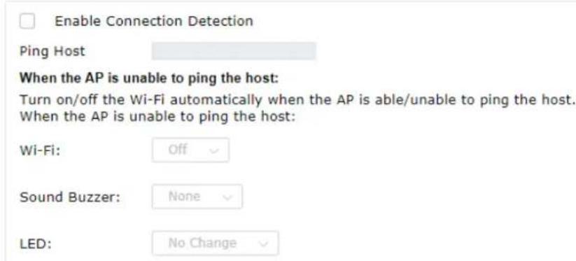
OK
Available settings are explained as follows:
| Item | Description |
| Enable Connection Detection | Check the box to enable such function. |
| Ping Host | Type an IP address (e.g., 8.8.8.8) or a domain name (e.g., google.com) for testing if the access point is stable or not. |
When the AP is unable to ping the host
| Wi-Fi | Off - When VigorAP is unable to ping the host, disconnect the W network.No Change - Wi-Fi network will keep the original state (no mater on or off) even VigorAP is unable to ping the host. |
| Sound Buzzer None - When the AP is unable to ping the host, VigorAP will not make any sound.Beep i ~ BeepV - When the AP is unable to ping the host, VigorAP will sound with the selected buzzer type. | |
| LED | Off - When VigorAP is unable to ping the host, the LED (2.4G/5G) be off automatically.No Change - When VigorAP is unable to ping the host, the LED (2.4G/5G) will keep the original state (no matter on or off). |
Click OK to save the settings.
IV-2-4 Sensor
A built-in sensor in this DrayTek AP will help you monitor itself and notify you if the device is overheating.
During summer in particular, it is important to ensure that VigorAP is not overheating due to cooling system failures.
The sensor of this VigorAP will continuously monitor the internal temperature of AP. When a pre-determined threshold is reached you will be alerted via Syslog.
Sensor Settings
Applications >> Sensor Setting
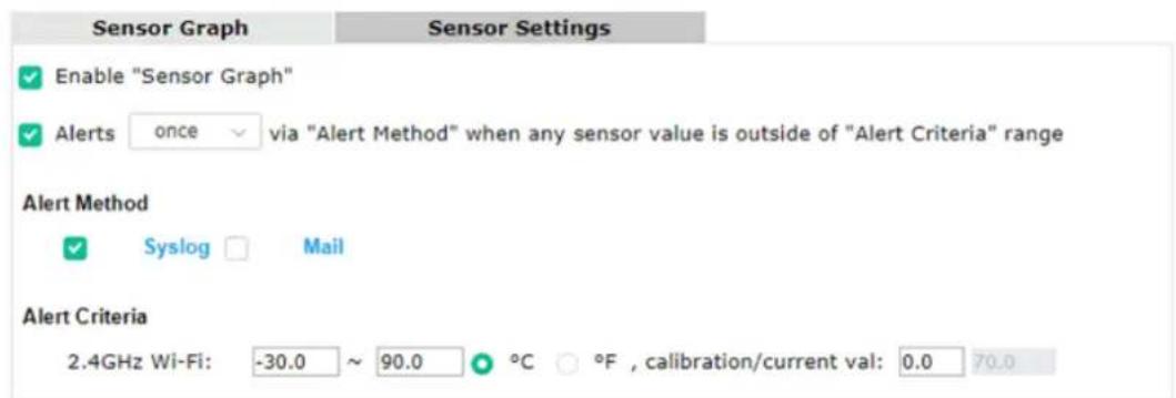
OK
Note:
- Wi-Fi temperature is only available when the selected Wi-Fi is enabled
Available settings are explained as follows:
| Item | Description |
| Enable "Sensor Graph" | Check it to display the sensor graph on Applications >> Sensor Setting >> Sensor Graph. |
| Alerts once/per min via ..... | It can determine the time/interval to send an alert message.Once - An alert will be sent out once when the sensor value is outside the range defined in Alert Criteria.Per min. - Alert message will be sent out per minute when the sensor value is outside the range defined in Alert Criteria. |
| Alert Method Syslog - The log containing the alarm message will be recorded on Syslog if it is enabled.Mail - The log containing the alarm message will be sent by mail. | |
| Alert Criteria | Alert message will be sent out according to the rules specified in this field.2.4GHz Wi-Fi - The temperature reading for 2.4G Wi-Fi network operation is estimated by using 2.4GHz CPU Wi-Fi module.The built-in sensor of VigorAP contains temperature sensor. Please type the upper limit and lower limit for VigorAP system to send out temperature alert.Calibration / current val- Type values used for correcting the |
temperature error.
C^/F^ - Choose the display unit of the temperature. There are two types for you to choose.
Temperature Sensor Graph
Below shows an example of temperature graph:
Applications >> Sensor Graph
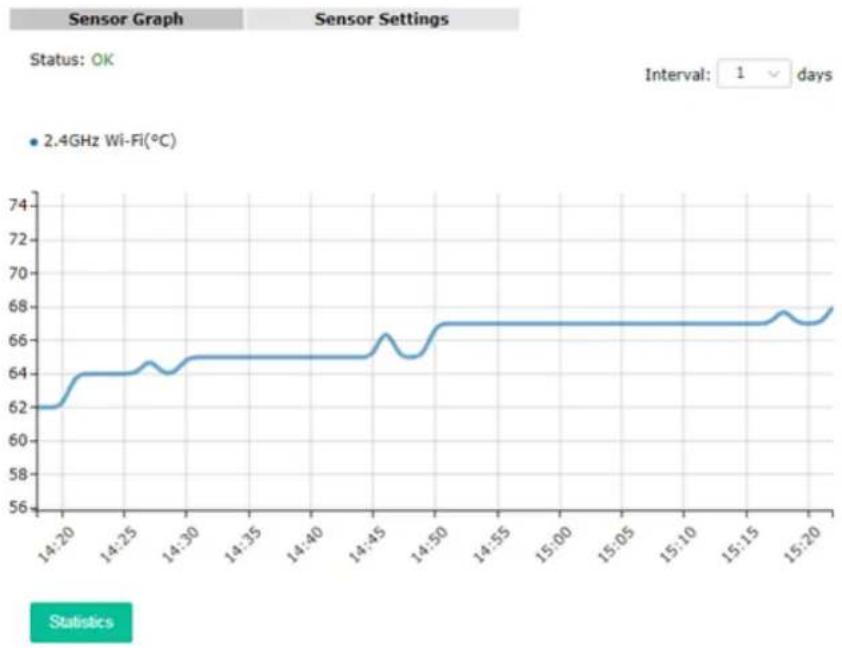
line
| Time | Wi-Fi (°C) | | -------- | ---------- | | 14:20 | 62 | | 14:25 | 64 | | 14:30 | 65 | | 14:35 | 65 | | 14:40 | 65 | | 14:45 | 66 | | 14:50 | 67 | | 14:55 | 67 | | 15:00 | 67 | | 15:05 | 67 | | 15:10 | 67 | | 15:15 | 67 | | 15:20 | 68 |IV-3 Objects Setting
Below shows the menu items for Objects Setting.
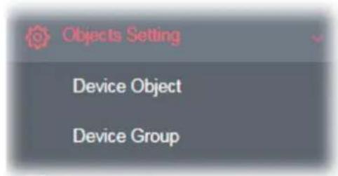
IV-3-1 Device Object
VigorAP can specify a client as a device object to be used by other applications.
Objects Setting >> Device Object
Create from Wireless Station Table
Create from Wireless Neighbor Table
Create from ARP Table
Device Object Profiles
Set to Factory Default
| Index | MAC | Name | Index | MAC | Name |
| 1 | 17 | ||||
| 2 | 18 | ||||
| 3 | 19 | ||||
| 4 | 20 | ||||
| 5 | 21 | ||||
| 6 | 22 | ||||
| 7 | 23 | ||||
| 8 | 24 | ||||
| 9 | 25 | ||||
| 10 | 26 | ||||
| 11 | 27 | ||||
| 12 | 28 | ||||
| 13 | 29 | ||||
| 14 | 30 | ||||
| 15 | 31 | ||||
| 16 | 32 |
Available settings are explained as follows:
| Item | Description |
| Create from Wireless Station Table | Click the link to open the following page.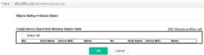 Choose the one(s) you want and click OK. The selected entries will be listed on the Device Object Profiles. Choose the one(s) you want and click OK. The selected entries will be listed on the Device Object Profiles. |
| Create from Wireless Neighbor Table | Click the link to open the following page. Objects Setting =>Device Object 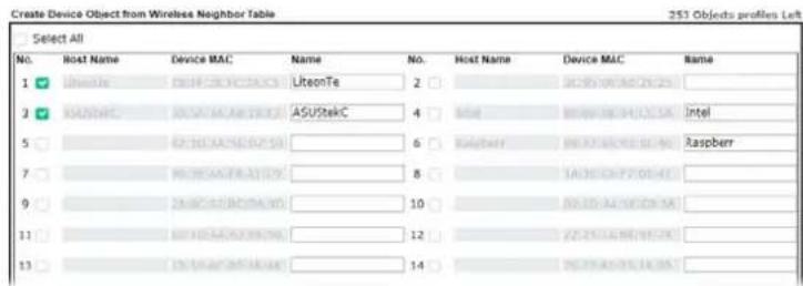 Choose the one(s) you want and click OK. The selected entries will be listed on the Device Object Profiles. Choose the one(s) you want and click OK. The selected entries will be listed on the Device Object Profiles. |
| Create from ARP Table | Click the link to open the following page. Objects Setting =>Device Object  Choose the one(s) you want and click OK. The selected entries will be listed on the Device Object Profiles. Choose the one(s) you want and click OK. The selected entries will be listed on the Device Object Profiles. |
| Set to Factory Default | Click it to return to the factory default setting and remove all the device object profiles. |
| Index Display the index number of device object profile. | |
| MAC Display the MAC address specified by the device object profile. | |
| Name Display the name of the device object profile. | |
| Back ACL Cfg Backup - Click to backup current configuration. | |
| Upload From File Browse - Click to upload the selected file onto Vigor device. Restore - Click to restore the configuration file with the selected file. | |
In addition to choosing from the wireless station table, neighbor table or ARP table, you can click any index number link to create a new device object profile by entering the name and MAC address manually.
Objects Setting >> Device Object
Profile Index : 1
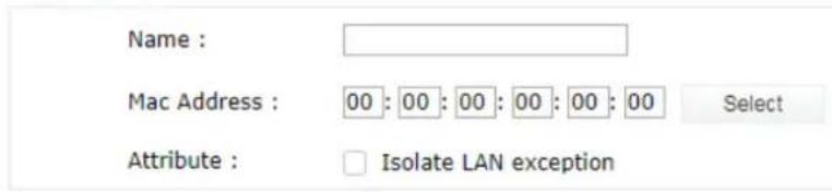

| Item | Description |
| Name Enter the name of the profile. | |
| Mac Address Enter the MAC address of the client. | |
| Attribute | Check the box to ignore the function of Isolate LAN. |
| OK Save the settings. | |
| Clear Remove the settings. | |
| Cancel Discard the settings and return to previous page. | |
IV-3-3 Device Group
Clients can be integrated as a group and be used by other applications.
Objects Setting >> Device Group
| Index | Name | Index | Name |
| 1 | 17 | ||
| 2 | 18 | ||
| 3 | 19 | ||
| 4 | 20 | ||
| 5 | 21 | ||
| 6 | 22 | ||
| 7 | 23 | ||
| 8 | 24 | ||
| 9 | 25 | ||
| 10 | 26 | ||
| 11 | 27 | ||
| 12 | 28 | ||
| 13 | 29 | ||
| 14 | 30 | ||
| 15 | 31 | ||
| 16 | 32 |

Available settings are explained as follows:
| Item | Description |
| Set to Factory Default | Click it to return to the factory default setting and remove all the device group profiles. |
| Index Display the index number of the device group profile. | |
| Name Display the name of the device group profile. | |
Click any index number link to create a new device group profile.
Objects Setting >> Device Group
Profile Index : 1
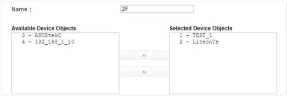

Available settings are explained as follows:
| Item | Description |
| Name Enter the name of the new group profile. | |
| Available Device Objects | Display current available device objects.Choose the one(s) and click the >> button to move them under the Selected IP Objects. |
| Selected Device Objects | Display the selected device objects.Choose the one(s) and click the << button to discard the selections. |
| OK Save the settings. | |
| Clear Remove the settings. | |
| Cancel Discard the settings and return to previous page. | |
Chapter V Mobile APP, DrayTek Wireless

natural_image
Abstract icon of a stylized hand holding a document, rendered in red and gray (no text or symbols)V-1 Introduction of DrayTek Wireless
VigorAP 1000C supports Android/iOS APP : DrayTek Wireless. The mobile user can find the APP through Apple App Store / Google Play Store.
Note:
Before using the DrayTek Wireless APP, please ENABLE your Wi-Fi feature first. Then, select the Wi-Fi network with Vigor access point(s) connected physically.
It is not necessary to connect to VigorAP physically. The mobile user must connect to one network with the same subnet as the VigorAP.
V-2 Create a New Network
- Run DrayTek Wireless APP.

- The system will open the NETWORK page to ask you create a new network first.
- There are two methods for creating a new network. Click "+" or press the search button
A: Click "+" to enter the next page. Enter the required information for the device that you want to create a network.
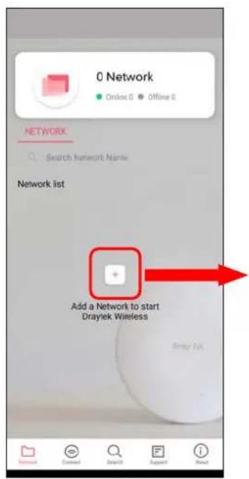
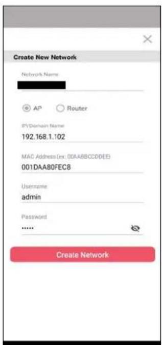
B: Press the search button. Later, the system will show the device searched. Select the one you want and click the name to get the detailed information.
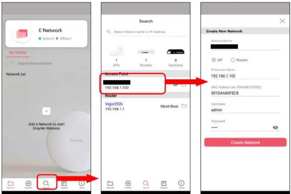
- After clicking Create Network, a new network will be shown on the screen.
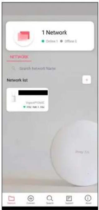
V-3 Wizard - Mesh Root and Mesh Node
The wizard can assist to configure mesh root and mesh node(s).
- Click and hold the network item till available actions (Wizard, Edit and Delete) shown on the screen. Select and click Wizard.
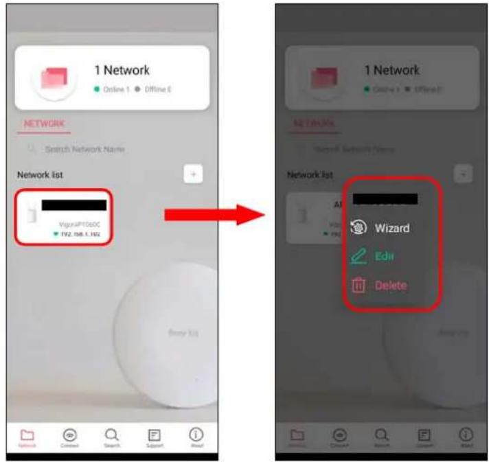
- After clicking Wizard, select Mesh Root as the Operation Mode. The default Group Name is VigorMesh. Change the name if required. Click Next to enter the next page.

On the WiFi Name & Password page, enter the WiFi Name and the password (should be the same as the security settings set on the device's WUI). You can also enable 2nd SSID by enabling the function of 2nd WiFi. Then click the Next button.
- On the Password Setting page, enter the admin password and confirm the password. Then click Next for the APP to verify the password. If successful, the Finish button will appear.
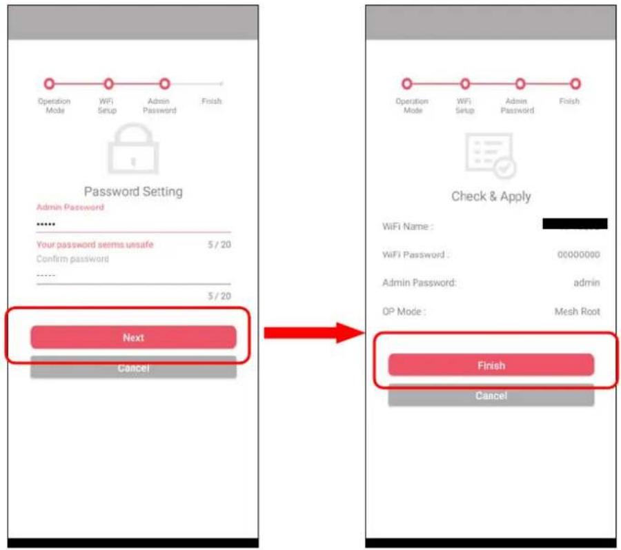
- After sending configuration to VigorAP, it will take some time to take effect. Now, the VigorAP has been set as Mesh Root. You can search several Mesh Nodes which do not belong to any other mesh group by clicking Next.
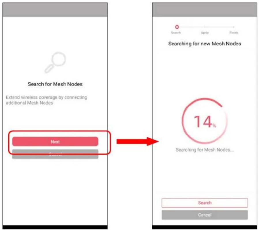
- Later, available VigorAP devices will be shown as the left figure below. Choose the Mesh Node you want to add and give a device name (e.g., VigorAP903) for it. The selected mesh node(s) will be grouped under such mesh root. Click Next. After checking the quantity of mesh node and mesh information and click Apply.
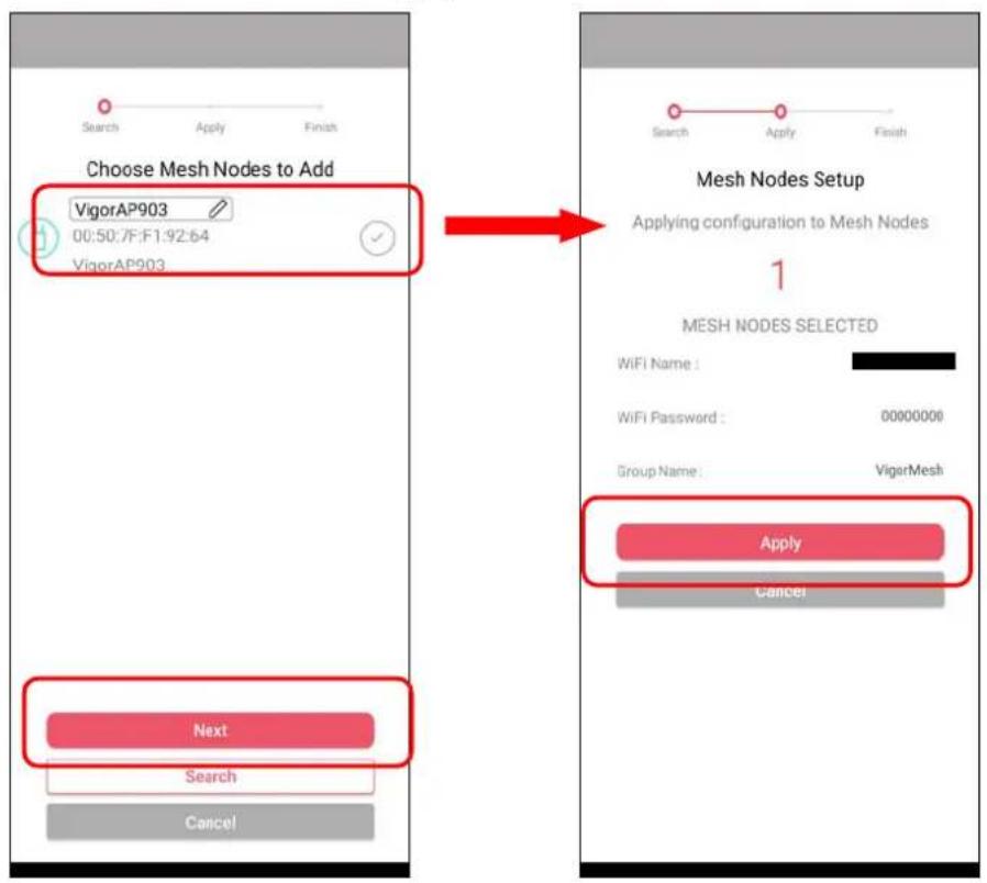
- Wait until the mesh root applies general configuration to the mesh nodes. Later, current status of the mesh node(s) will be shown on the following page. Click Finish.
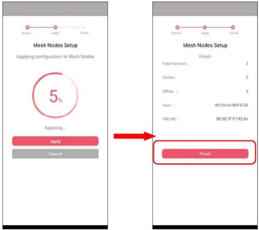
- A network with mesh root and mesh node has been set up successfully.
Run DrayTek Wireless APP.
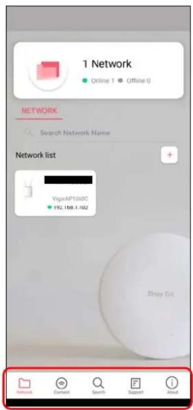
Available settings are explained as follows:
| Item | Description |
| Network Create a new network. | |
| Connect Connect to a device (AP/CPE). | |
| Search Search available devices for connection. | |
| Support Display a list of models supported by this APP. | |
| About Display the version information of this APP. | |
V-4-1 Network
The Network page allows you to search devices (CPE/AP) for creating a network or editing an existing network (refer to V-2 for detailed information).
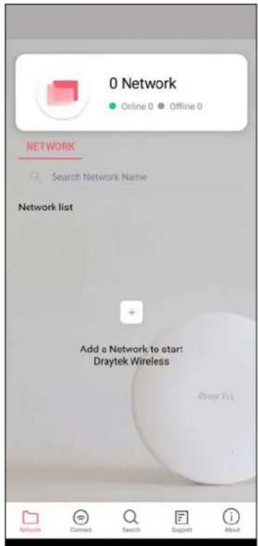
For checking the general information of certain device, click the existing item under the Network list to open the Dashboard of the selected device.
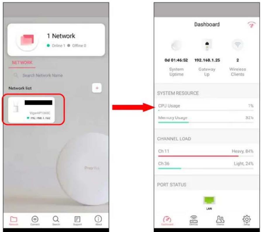
V-4-2 Connect
For viewing the detailed information of a selected CPE/AP, click the Connect icon (Connect) to open the following left figure. Enter the SSID, password and select an encryption mode of the device.
Then click the Connect button (Connect) for accessing into the dashboard of the device.
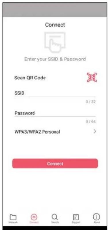
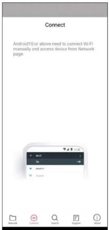
Or, click Scan (28) to scan the QR code printed on VigorAP packaging box to connect the designated VigorAP.
V-4-2-1 Dashboard of the Device
Below shows the dashboard of the device. Use the scroll bar up and down for viewing other information.
Information for Mesh Root Mode
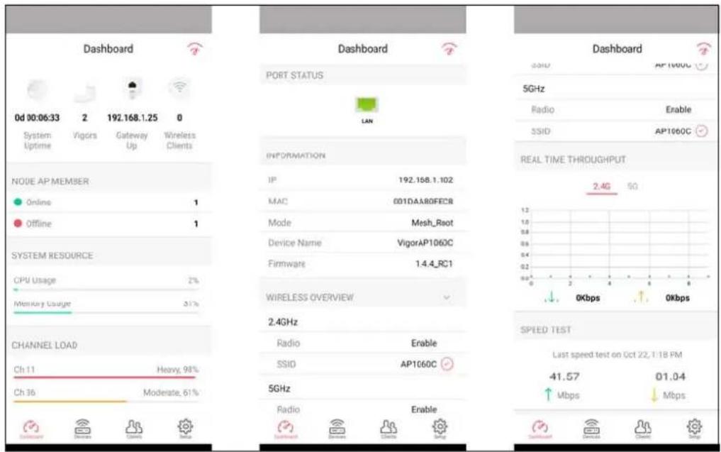
Information for AP Mode
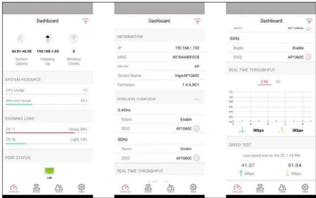
Available settings are explained as follows:
| Item | Description |
| Dashboard The dashboard is designed with Responsive Web Design. You can click Dashboard to connect to the selected VigorAP WUI. | |
| Devices All of the devices (mesh root and mesh nodes) controlled by the mesh group will be shown on this page. One mesh group contains up to eight devices. | |
| Clients | Displays general information for all clients / groups in Mesh Group. |
| Setup Configures TR-069, Manage and WLAN settings for the connected VigorAP. | |
V-4-2-2 Devices
Below shows the icon view and list view of the device. One mesh group contains up to eight devices. Icon view and List view for Mesh Root Mode
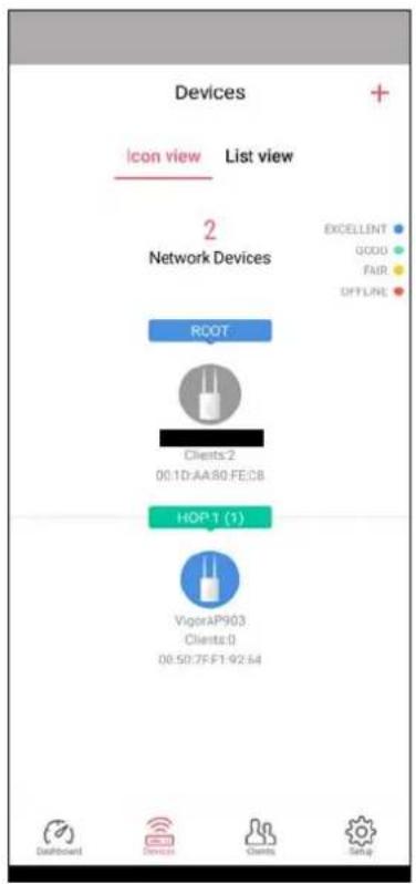
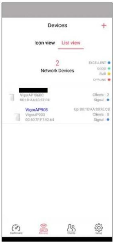
Available settings are explained as follows:
| Item | Description |
| Icon view / List view | Switch to display the network devices in icons or a list. |
| "+" To add more mesh node, click the "+" link. | |
Device for AP Mode
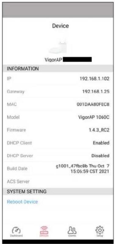
Available settings are explained as follows:
| Item | Description |
| INFORMATION | Display general information of the device (e.g., IP address, Gateway, MAC and etc.) |
| SYSTEM SETTINGS Reboot Device - Click to reboot the device immediately. | |
V-4-2-3 Clients / Groups
This page shows relationship between devices and groups.
All client members can be classified (into groups). Additionally, the network connection time of the device group can be adjusted.
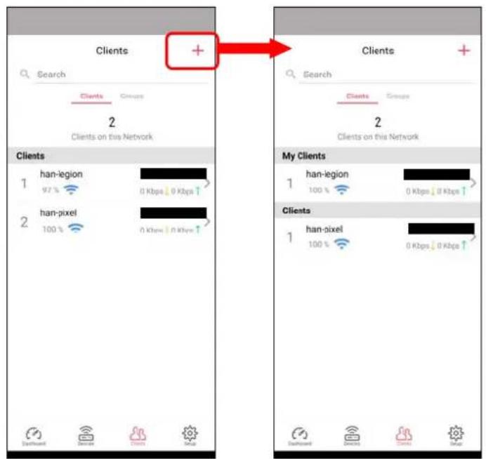
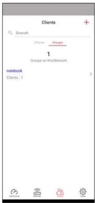
Available settings are explained as follows:
| Item | Description |
| Search Search available CPE/AP around. | |
| Clients | + - Click it to open the page containing My Clients for adding new clients under My Clients.My Clients- Devices under this area can be classified under a group.Clients- Displays devices which have not been classified under any network group. |
| Groups Displays the group member and action. | |
| + - Click it to display the items listed under My Clients. Select the one you want to add it under current group. | |
Click the group to access the group setup page. If required, click Edit to add or remove the group member. Or click Pause Schedule to modify the schedule of the group.
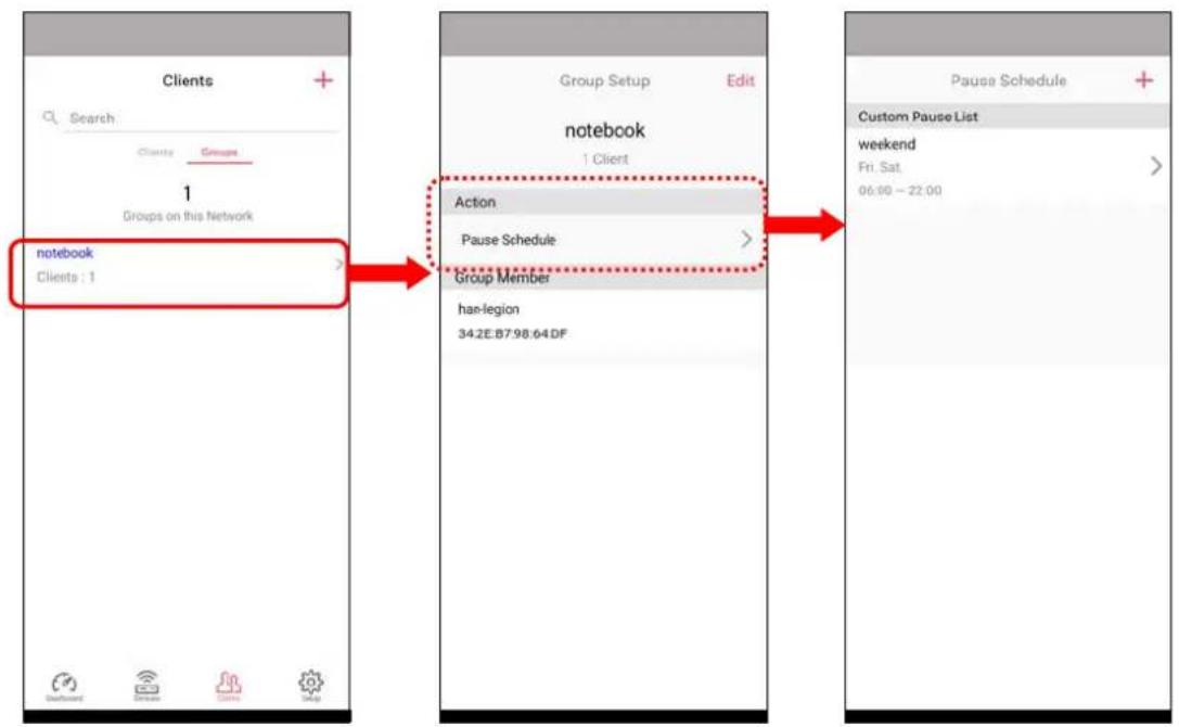
V-4-2-4 Setup
Setup page is used for configuring TR-069, Admin Password, Wireless LAN and Wi-Fi Blocklist settings of the Vigor device.
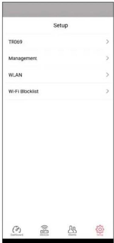
Chapter VI Troubleshooting

natural_image
Abstract graphic of a red wrench crossed with two gray hexagonal shapes (no text or symbols)VI-1 Diagnostics
This section will guide you to solve abnormal situations if you cannot access into the Internet after installing the router and finishing the web configuration. Please follow sections below to check your basic installation status stage by stage.
- Checking if the hardware status is OK or not.
- Checking if the network connection settings on your computer are OK or not.
- Pinging the router from your computer.
- Checking if the ISP settings are OK or not.
- Backing to factory default setting if necessary.
If all above stages are done and the router still cannot run normally, it is the time for you to contact your dealer or DrayTek technical support for advanced help.
Diagnostic tools provide a useful way to view or diagnose the status of your VigorAP 1000C.
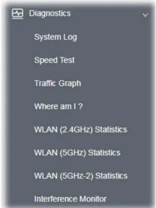
VI-1-1 System Log
At present, only System Log is offered.
Diagnostics >> System Log
System Log Information
| Clear | Refresh | □ Line wrap |
Mar 2 09:20:29 kernel: [330839.940723] ol_scan_unregister_event_handler: Failed to unregi
Mar 2 09:20:29 kernel: [330839.940723]
Mar 2 09:20:29 kernel: [330839.950384] osif_vap_stop: Scan in progress.. Cancelling it. vap
Mar 2 09:20:29 kernel: [330839.975642] br0: port 7(ath90) entered forwarding state
Mar 2 09:20:29 kernel: [330839.986752] Auto Channel Select :
Mar 2 09:20:29 kernel: [330839.986767] 100 104
Mar 2 09:20:29 kernel: [330839.986783] 108 112
Mar 2 09:20:29 kernel: [330839.986794] 116 120
Mar 2 09:20:29 kernel: [330839.986805] 124 128
Mar 2 09:20:29 kernel: [330839.988500] br0: port 7(ath90) entered disabled state
Mar 2 09:20:30 kernel: [330840.815668] br0: port 8(ath91) entered forwarding state
Mar 2 09:20:31 kernel: [330842.023482] osif_vap_init: Scan in progress.. Cancelling it. vap:
Mar 2 09:20:31 kernel: [330842.031806] osif_vap_init: Failed to cancel Scanl
Mar 2 09:20:31 kernel: [330842.066917] br0: port 7(ath90) entered forwarding state
Mar 2 09:20:31 kernel: [330842.071313] br0: port 7(ath90) entered forwarding state
Mar 2 09:20:31 kernel: [330842.077461] 8021q: adding VLAN 0 to HW filter on device ath90
Mar 2 09:20:31 kernel: [330842.158674] ol_scan_unregister_event_handler: Failed to unreq
VI-1-2 Speed Test
Click the Start button on the page to test the speed. Such feature can help you to find the best installation place for Vigor AP.
Diagnostics >> Speed Test
Speed Test
Welcome to VigorAP1000C Speed Test.
This test allows you to find out the best place for VigorAP1000C. You can execute the speed test at different places of the building and select the best location for it. The performance test result is only for your reference.
Start
VI-1-3 Traffic Graph
Click Traffic Graph to open the web page. Choose one of the managed Access Points, LAN-A or LAN-B, daily or weekly for viewing data transmission chart. Click Refresh to renew the graph at any time.
Diagnostics >> Traffic Graph
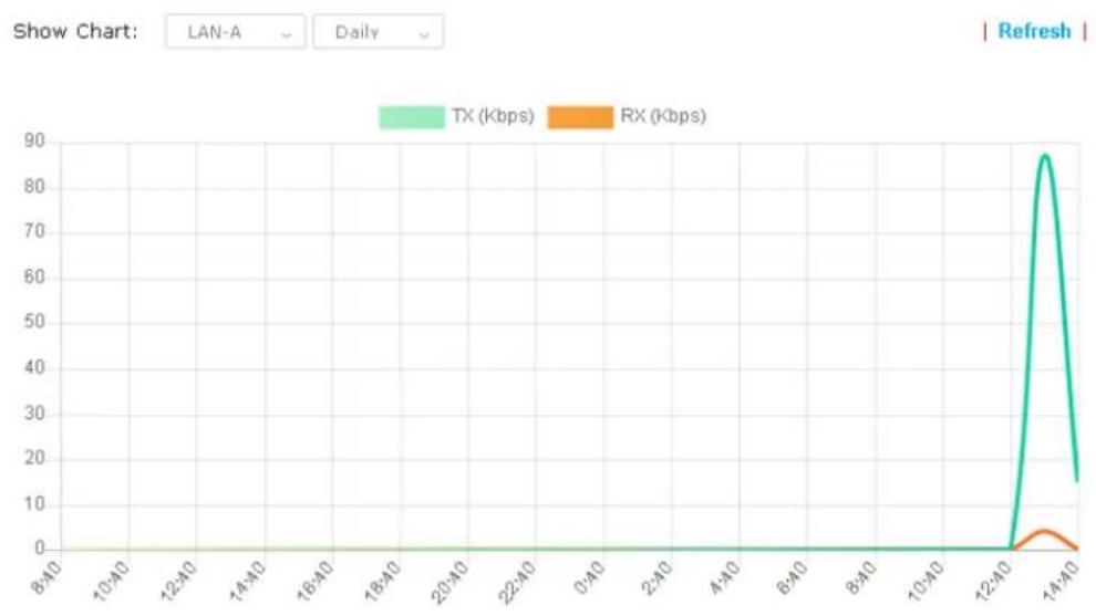
line
| Time | TX (Kbps) | RX (Kbps) | |--------|-----------|-----------| | 8:40 | 0 | 0 | | 10:40 | 0 | 0 | | 12:40 | 0 | 0 | | 14:40 | 87 | 3 |The horizontal axis represents time; the vertical axis represents the transmission rate (in kbps).
VI-1-4 Where am I
This function is useful for the administrator to locate the access points to build the best signal transmitting position for multiple access points.
Diagnostics >> Where am I?
Where am I?
Welcome to VigorAP1000C Where am I?
The buzzer will sound when the "Sound" button is clicked. This is useful for network administrators to locate the access point.
Sound Beep i for 6 second(s) Sound Stop
Available parameters are explained as follows:
| Item | Description |
| Sound Use the drop down list to specify a special sound for such access point. | |
| for XX seconds Set the duration time of the beep sound. | |
Sound Activate the buzzer of the access point.
Stop Terminate the buzzer of the access point.
VI-1-5 WLAN (2.4GHz) Statistics
Such page is used for debug by RD only.
Diagnostics >> WLAN (2.4GHz) Statistics

Auto-Refresh
Refresh
| Tx Data Packets | 0 | Rx Data Packets | 0 |
| Tx Data Bytes | 0 | Rx Data Bytes | 0 |
| Average Tx Rate (kbps) | No Station | Average Rx Rate (kbps) | No Station |
| Tx Unicast Data Packets | 0 | Rx PHY errors | 0 |
| Tx Multi/Broadcast Data Packets | 0 | Rx CRC errors | 737 |
| Tx failures | 0 | Rx MIC errors | 0 |
| Rx Decryption errors | 0 | ||
| Rx errors | 0 |
| SSID1(DrayTek-04F2C8) | SSID2(marketing) | SSID3(N/A) | SSID4(N/A) | |
| Tx Data Packets | 0 | 0 | N/A | N/A |
| Tx Data Bytes | 0 | 0 | N/A | N/A |
| Tx Data BytesTx Data Payload Bytes | 0 | 0 | N/A | N/A |
| Rx Data Packets | 0 | 0 | N/A | N/A |
| Rx Data Bytes | 0 | 0 | N/A | N/A |
| Rx Data Payload Bytes | 0 | 0 | N/A | N/A |
| Tx Unicast Data Packets | 0 | 0 | N/A | N/A |
| Tx Multi/Broadcast Data Packets | 0 | 0 | N/A | N/A |
| Average Tx Rate (kbps) | No Station | No Station | N/A | N/A |
| Average Rx Rate (kbps) | No Station | No Station | N/A | N/A |
| Rx errors | 0 | 0 | N/A | N/A |
| Tx failures | 0 | 0 | N/A | N/A |
VI-1-6 WLAN (5GHz) Statistics
Such page is used for debug by RD only.
Diagnostics >> WLAN (5GHz) Statistics

Auto-Refresh
Refresh
| Tx Data Packets | 0 | Rx Data Packets | 0 |
| Tx Data Bytes | 0 | Rx Data Bytes | 0 |
| Average Tx Rate (kbps) | No Station | Average Rx Rate (kbps) | No Station |
| Tx Unicast Data Packets | 0 | Rx PHY errors | 0 |
| Tx Multi/Broadcast Data Packets | 0 | Rx CRC errors | 12673 |
| Tx failures | 0 | Rx MIC errors | 0 |
| Rx Decryption errors | 0 | ||
| Rx errors | 0 |
| SSID1(DrayTek-04F2C8) | SSID2(marketing) | SSID3(N/A) | SSID4(N/A) | |
| Tx Data Packets | 0 | 0 | N/A | N/A |
| Tx Data Bytes | 0 | 0 | N/A | N/A |
| Tx Data BytesTx Data Payload Bytes | 0 | 0 | N/A | N/A |
| Rx Data Packets | 0 | 0 | N/A | N/A |
| Rx Data Bytes | 0 | 0 | N/A | N/A |
| Rx Data Payload Bytes | 0 | 0 | N/A | N/A |
| Tx Unicast Data Packets | 0 | 0 | N/A | N/A |
| Tx Multi/Broadcast Data Packets | 0 | 0 | N/A | N/A |
| Average Tx Rate (kbps) | No Station | No Station | N/A | N/A |
| Average Rx Rate (kbps) | No Station | No Station | N/A | N/A |
| Rx errors | 0 | 0 | N/A | N/A |
| Tx failures | 0 | 0 | N/A | N/A |
VI-1-7 WLAN (5GHz-2) Statistics
Such page is used for debug by RD only.
Diagnostics >> WLAN (5GHz-2) Statistics

Auto-Refresh
Refresh
| Tx Data Packets | 0 | Rx Data Packets | 0 |
| Tx Data Bytes | 0 | Rx Data Bytes | 0 |
| Average Tx Rate (kbps) | No Station | Average Rx Rate (kbps) | No Station |
| Tx Unicast Data Packets | 0 | Rx PHY errors | 901493 |
| Tx Multi/Broadcast Data Packets | 0 | Rx CRC errors | 7430 |
| Tx failures | 0 | Rx MIC errors | 0 |
| Rx Decryption errors | 0 | ||
| Rx errors | 0 |
| SSID1(DrayTek-04F2C8) | SSID2(marketing) | SSID3(N/A) | SSID4(N/A) | |
| Tx Data Packets | 0 | 0 | N/A | N/A |
| Tx Data Bytes | 0 | 0 | N/A | N/A |
| Tx Data BytesTx Data Payload Bytes | 0 | 0 | N/A | N/A |
| Rx Data Packets | 0 | 0 | N/A | N/A |
| Rx Data Bytes | 0 | 0 | N/A | N/A |
| Rx Data Payload Bytes | 0 | 0 | N/A | N/A |
| Tx Unicast Data Packets | 0 | 0 | N/A | N/A |
| Tx Multi/Broadcast Data Packets | 0 | 0 | N/A | N/A |
| Average Tx Rate (kbps) | No Station | No Station | N/A | N/A |
| Average Rx Rate (kbps) | No Station | No Station | N/A | N/A |
| Rx errors | 0 | 0 | N/A | N/A |
| Tx failures | 0 | 0 | N/A | N/A |
VI-1-8 Interference Monitor
As an interference detector, VigorAP can detect all of the environmental interference factors for certain channel used or for all of the wireless channels.
Current Channel
The analysis page with information about wireless band, channel, transmission power, bandwidth, wireless mode, and country code chosen will be displayed on this page completely based on the wireless band (2.4G or 5G or 5G-2) selected. Also, channel status can be seen easily from this page.
Diagnostics >> Interference Monitor
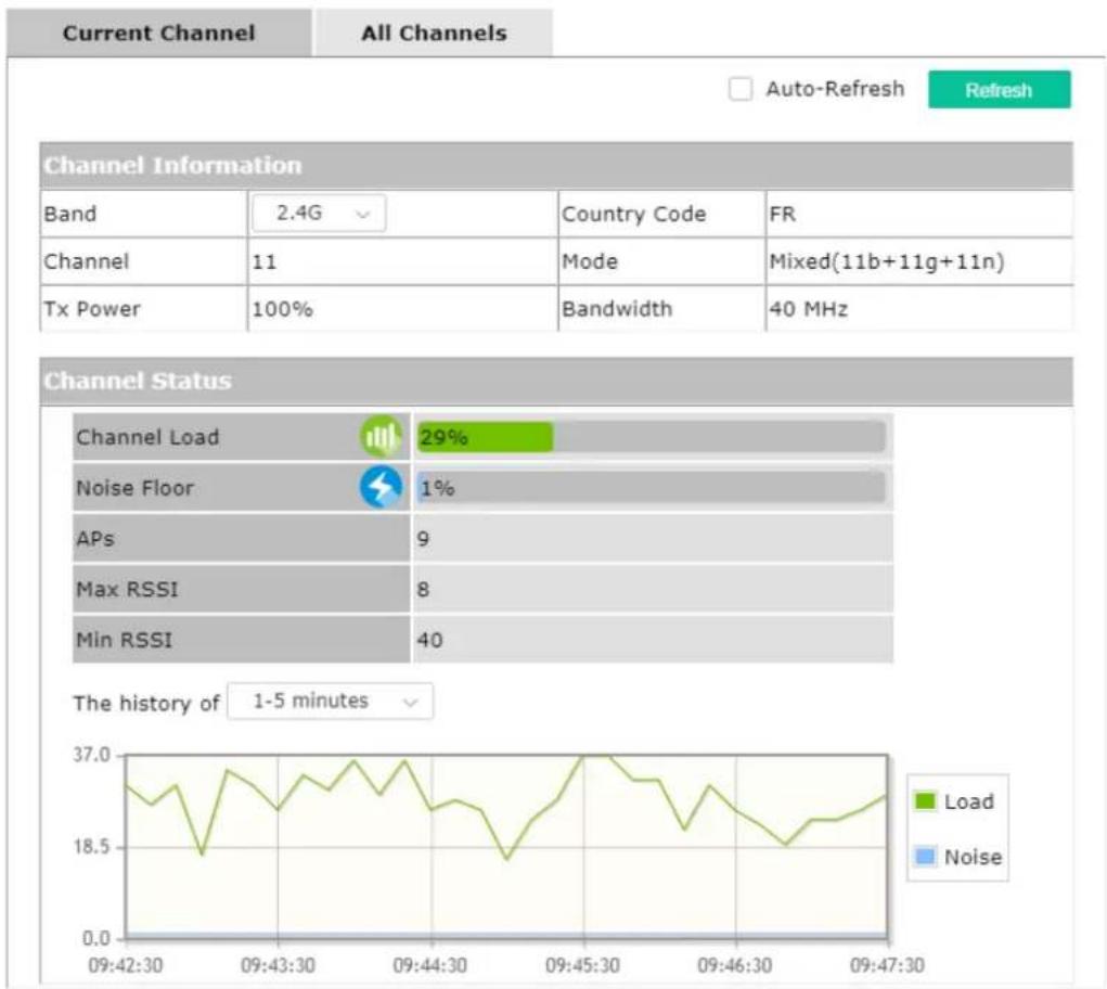
line
| Metric | Value | | ---------------- | ----- | | Channel Load | 29% | | Noise Floor | 1% | | APs | 9 | | Max RSSI | 8 | | Min RSSI | 40 |All Channels
This page displays the utilization and energy result for all channels based on 2.4G/5G. Click Refresh to get the newly update interference situation.
Diagnostics >> Interference Monitor
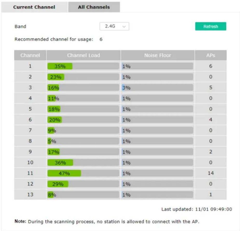
bar
| Channel | Channel Load (%) | Noise Floor (%) | | :--- | :--- | :--- | | 1 | 35 | 1 | | 2 | 23 | 1 | | 3 | 16 | 3 | | 4 | 11 | 1 | | 5 | 18 | 1 | | 6 | 20 | 1 | | 7 | 9 | 1 | | 8 | 5 | 1 | | 9 | 17 | 1 | | 10 | 36 | 1 | | 11 | 47 | 1 | | 12 | 29 | 1 | | 13 | 8 | 1 | Last updated: 11/01 09:49:00 Note: During the scanning process, no station is allowed to connect with the AP.VI-1-9 Support Area
When you click Support Area, you will be guided to visit www.draytek.com and open the corresponding pages directly.
VI-2 Checking the Hardware Status
Follow the steps below to verify the hardware status.
- Check the power line and cable connections.
Refer to "I-2 Hardware Installation" for details.
-
Power on the modem. Make sure the POWER LED, ACT LED and LAN LED are bright.
-
If not, it means that there is something wrong with the hardware status. Simply back to "I-2 Hardware Installation" to execute the hardware installation again. And then, try again.
VI-3 Checking the Network Connection Settings
Sometimes the link failure occurs due to the wrong network connection settings. After trying the above section, if the link is stilled failed, please do the steps listed below to make sure the network connection settings is OK.
VI-3-1 For Windows
Note:
The example is based on Windows 7 (Professional Edition). As to the examples for other operation systems, please refer to the similar steps or find support notes in www.draytek.com.
- Open All Programs>>Getting Started>>Control Panel. Click Network and Sharing Center.
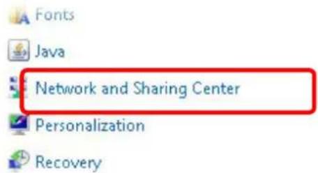
- In the following window, click Change adapter settings.
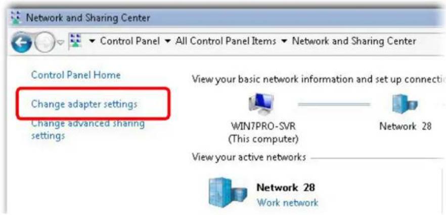
- Icons of network connection will be shown on the window. Right-click on Local Area Connection and click on Properties.
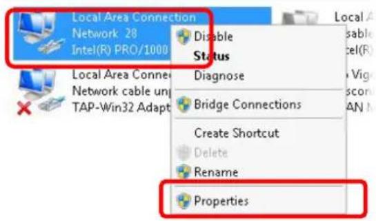
- Select Internet Protocol Version 4 (TCP/IP) and then click Properties.
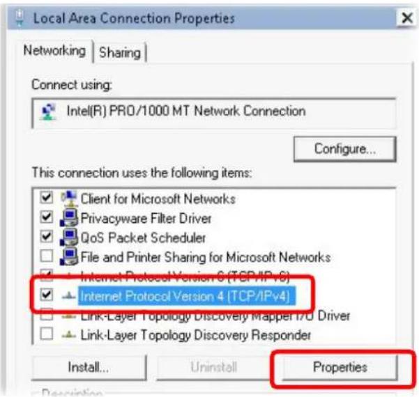
- Select Obtain an IP address automatically and Obtain DNS server address automatically. Finally, click OK.
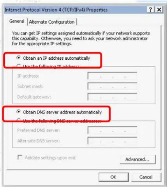
VI-3-2 For Mac Os
- Double click on the current used Mac Os on the desktop.
- Open the Application folder and get into Network.
- On the Network screen, select Using DHCP from the drop down list of Configure IPv4.
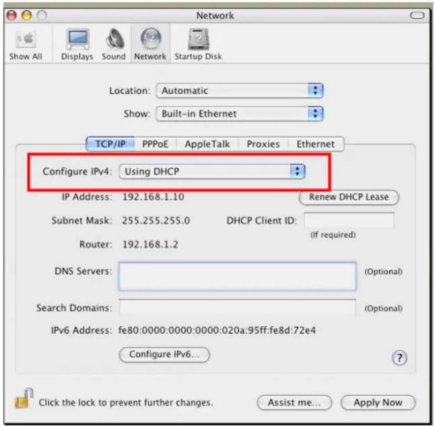
VI-4 Pinging the Device
The default gateway IP address of the modem is 192.168.1.2. For some reason, you might need to use "ping" command to check the link status of the modem. The most important thing is that the computer will receive a reply from 192.168.1.2. If not, please check the IP address of your computer. We suggest you setting the network connection as get IP automatically. (Please refer to the section V-2)
Please follow the steps below to ping the modem correctly.
VI-4-1 For Windows
-
Open the Command Prompt window (from Start menu> Run).
-
Type command (for Windows 95/98/ME) or cmd (for Windows NT/2000/XP/Vista/7). The DOS command dialog will appear.
![Microsoft Windows XP [Version 5.1.2600] (C) Copyright 1985-2001 Microsoft Corp. D:\Documents and Settings\fae>ping 192.168.1.2 Pinging 192.168.1.2 with 32 bytes of data: Reply from 192.168.1.2: bytes=32 time<1ms TTL-255 Reply from 192.168.1.2: bytes=32 time<1ms TTL-255 Reply from 192.168.1.2: bytes=32 time<1ms TTL-255 Reply from 192.168.1.2: bytes=32 time<1ms TTL-255 Ping statistics for 192.168.1.2: Packets: Sent = 4, Received = 4, Lost = 0 (0% loss), Approximate round trip times in milli-seconds: Minimum = 0ms, Maximum = 0ms, Average = 0ms D:\Documents and Settings\fae)_](/content/2026/05/898472/images/e7395d4b399abcf4a3174458542e4ebfcb629c5fb7002e064c0b6263f63b6718.jpg)
-
Type ping 192.168.1.2 and press [Enter]. If the link is OK, the line of "Reply from 192.168.1.2:bytes=32 time<1ms TTL=255" will appear.
-
If the line does not appear, please check the IP address setting of your computer
-
Double click on the current used Mac Os on the desktop.
-
Open the Application folder and get into Utilities.
-
Double click Terminal. The Terminal window will appear.
-
Type ping 192.168.1.2 and press [Enter]. If the link is OK, the line of "64 bytes from 192.168.1.2: icmp seq=0 ttl=255 time=xxxx ms" will appear.
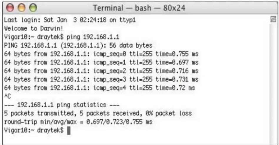
VI-5 Backing to Factory Default Setting
Sometimes, a wrong connection can be improved by returning to the default settings. Try to reset the modem by software or hardware.
i Warning:
After pressing factory default setting, you will loose all settings you did before. Make sure you have recorded all useful settings before you pressing. The password of factory default is null.
VI-5-1 Software Reset
You can reset the modem to factory default via Web page.
Go to System Maintenance and choose Reboot System on the web page. The following screen will appear. Choose Using factory default configuration and click OK. After few seconds, the modem will return all the settings to the factory settings.
System Maintenance >> Reboot System
Reboot System
Do You want to reboot your AP?

Using current configuration

Using factory default configuration
OK
VI-5-2 Hardware Reset
While the modem is running, press the Factory Reset button and hold for more than 5 seconds. When you see the ACT LED blinks rapidly, please release the button. Then, the modem will restart with the default configuration.

After restore the factory default setting, you can configure the settings for the modem again to fit your personal request.
VI-6 Contacting DrayTek
If the modem still cannot work correctly after trying many efforts, please contact your dealer for further help right away. For any questions, please feel free to send e-mail to support@draytek.com.
- VigorAP 1000C
- Intellectual Property Rights (IPR) Information
- Copyrights
- Trademarks
- Safety Instructions and Approval
- Safety Instructions
- Warranty
- Be a Registered Owner
- Firmware & Tools Updates
- Table of Contents
- Chapter I Installation ......VII
- Chapter II Connectivity .... 31
- Chapter III Management 95
- III-1 System Maintenance....96
- III-2 Central AP Management....110
- III-3 Mobile Device Management 116
- Chapter IV Others 127
- IV-1 RADIUS Setting.... 128
- IV-2 Applications....132
- IV-3 Objects Setting....139
- Chapter V Mobile APP, DrayTek Wireless.... 143
- V-1 Introduction of DrayTek Wireless....144
- V-3 Wizard - Mesh Root and Mesh Node 147
- V-4 Login....151
- Chapter VI Troubleshooting....159
- Chapter I Installation
- I-1 Introduction
- I-1-1 LED Indicators and Connectors
- Note:
- Interface Description
- I-2 Hardware Installation
- I-3 Network IP Configuration
- I-3-1 Windows 10 IP Address Setup
- I-4 Accessing to Web User Interface
- i Note:
- I-5 Changing Password
- Administrator Settings
- I-6 Dashboard
- I-7 Quick Start Wizard
- I-7-1 Settings for Access Point
- I-7-2 Settings for Mesh Root
- I-7-3 Settings for Mesh Node
- I-7-4 Settings for Range Extender
- When WPA/PSK or WPA2/PSK is selected:
- Chapter II Connectivity
- AP:
- Mesh :
- Mesh Root:
- Mesh Node:
- Range Extender :
- OK
- II-2 General Concepts for Wireless LAN
- Security Overview
- WPS Introduction
- II-3 Wireless LAN (2.4GHz/5GHz/5GHz-2) Settings for AP Mode
- II-3-1 General Setup
- II-3-2 Security
- II-3-3 Access Control
- II-3-4 WPS
- II-3-5 Advanced Setting
- II-3-6 AP Discovery
- II-3-7 WDS AP Status
- II-3-8 Bandwidth Management
- II-3-9 Airtime Fairness
- II-3-10 Station Control
- II-3-11 Roaming
- II-3-12 Band Steering (for Wireless LAN (2.4GHz))
- How to Use Band Steering?
- II-3-13 Station List
- II-3-13-1 Connected Number
- II-3-13-2 Statistics
- II-3-13-3 Clients List
- II-3-13-4 Block List
- II-3-13-5 White List
- II-4 Mesh Settings for Mesh Mode
- Mesh Root and Mesh Node
- II-4-1 Mesh Setup
- How to set up a mesh group?
- General Setup
- Mesh Group
- Add Mesh Node
- Backup Mesh Config
- Search List
- II-4-2 Mesh Status
- II-4-3 Mesh Discovery
- Scan
- II-4-4 Basic Config Sync
- Tips for Mesh Network Setup
- II-4-5 Advanced Config Sync
- II-4-6 Support List
- II-4-7 Mesh Syslog
- II-5 Universal Repeater Settings for Range Extender Mode
- Universal Repeater IP Configuration
- II-6-1 General Setup
- II-6-2 Hotspot Web Portal
- RADIUS Settings
- Whitelist Settings
- II-6-3 Port Settings
- Chapter III Management
- III-1 System Maintenance
- III-1-1 System Status
- III-1-3 Administrator Password
- III-1-4 User Password
- III-1-5 Configuration Backup
- Configuration Backup / Restoration
- Restoration
- Backup
- III-1-6 Syslog/Mail Alert
- III-1-7 Time and Date
- III-1-8 SNMP
- III-1-9 Management
- III-1-10 Reboot System
- Reboot System
- III-1-11 Firmware Upgrade
- Firmware Upgrade
- Firmware Update
- Firmware Version Status
- III-2 Central AP Management
- III-2-1 General Setup
- III-2-2 APM Log
- III-2-3 Overload Management
- III-2-4 Status of Settings
- III-3 Mobile Device Management
- III-3-1 Station List
- III-3-1-1 Connected Number
- III-3-1-2 Statistics
- III-3-1-3 Clients List
- III-3-1-5 White List
- III-3-2 Station Statistics
- III-3-3 Station Nearby
- III-3-4 Policies
- III-3-5 Station Control List
- Chapter IV Others
- IV-1 RADIUS Setting
- IV-1-1 RADIUS Server
- IV-1-2 Certificate Management
- IV-2 Applications
- IV-2-1 Schedule
- IV-2-2 Apple iOS Keep Alive
- Apple iOS Keep Alive:
- IV-2-3 Wi-Fi Auto On/Off
- Wi-Fi Auto On/Off
- IV-2-4 Sensor
- Sensor Settings
- Temperature Sensor Graph
- IV-3 Objects Setting
- IV-3-1 Device Object
- IV-3-3 Device Group
- Chapter V Mobile APP, DrayTek Wireless
- V-1 Introduction of DrayTek Wireless
- V-2 Create a New Network
- V-3 Wizard - Mesh Root and Mesh Node
- V-4-1 Network
- V-4-2 Connect
- V-4-2-1 Dashboard of the Device
- V-4-2-2 Devices
- Device for AP Mode
- V-4-2-3 Clients / Groups
- V-4-2-4 Setup
- Chapter VI Troubleshooting
- VI-1 Diagnostics
- VI-1-1 System Log
- System Log Information
- VI-1-2 Speed Test
- Speed Test
- VI-1-3 Traffic Graph
- VI-1-4 Where am I
- Where am I?
- VI-1-5 WLAN (2.4GHz) Statistics
- VI-1-6 WLAN (5GHz) Statistics
- VI-1-7 WLAN (5GHz-2) Statistics
- VI-1-8 Interference Monitor
- Current Channel
- All Channels
- VI-1-9 Support Area
- VI-2 Checking the Hardware Status
- VI-3 Checking the Network Connection Settings
- VI-3-1 For Windows
- VI-3-2 For Mac Os
- VI-4 Pinging the Device
- VI-4-1 For Windows
- VI-5 Backing to Factory Default Setting
- i Warning:
- VI-5-1 Software Reset
- VI-5-2 Hardware Reset
- VI-6 Contacting DrayTek
Brand : Draytek
Model : Vigor AP 1000C
Category : Access Point