
TUS96C71BX - Oven LA GERMANIA - Free user manual and instructions
Find the device manual for free TUS96C71BX LA GERMANIA in PDF.


| Product Type | Built-in Electric Oven |
| Brand | La Germania |
| Model | TUS96C71BX |
| Product Category | Oven |
| Installation Type | Built-in |
| Color | Stainless Steel / Black |
| Dimensions (Approx.) | 59.5 cm (W) x 59.5 cm (H) x 56.5 cm (D) |
| Weight (Approx.) | 35 kg |
| Power Supply | 220-240 V ~ 50/60 Hz, 16 A |
| Total Power Consumption | 3.0 kW (approx.) |
| Energy Efficiency Class | A+ (estimated) |
| Oven Capacity | 70 L (approx.) |
| Oven Functions | Convection, Grill, Fan-assisted, Pizza, Defrost, Light |
| Control Type | Touch + Rotary Knobs |
| Display | Digital LED |
| Cleaning | Catalytic / Easy-clean enamel interior |
| Safety Features | Child lock, Automatic shut-off, Cool-touch door |
| Accessories Included | 2 baking trays, 1 wire grill, 1 drip tray |
| Spare Parts Availability | Authorized service centers; heating elements, door gaskets, knobs |
| Repairability | Modular design; replaceable components |
| Warranty | 2 years (standard) |
| User Manual | Available in PDF (32 pages) |
Frequently Asked Questions - TUS96C71BX LA GERMANIA
User questions about TUS96C71BX LA GERMANIA
0 question about this device. Answer the ones you know or ask your own.
Ask a new question about this device
Download the instructions for your Oven in PDF format for free! Find your manual TUS96C71BX - LA GERMANIA and take your electronic device back in hand. On this page are published all the documents necessary for the use of your device. TUS96C71BX by LA GERMANIA.
USER MANUAL TUS96C71BX LA GERMANIA
INSTALLATION, MAINTENANCE AND USE INSTRUCTIONS FOR FREE-STANDING COOKERS 90x60 cm GIANT OVEN
APPLY DATA LABELS
READ THE INSTRUCTION BOOKLET BEFORE INSTALLING AND USING THE APPLIANCE.
It is important that you retain these instructions, proof of purchase as well as other important documents about this product for future reference.
The manufacturer will not be responsible for any damage to property or to persons caused by incorrect installation or improper use of the appliance.
Due to continual product development, Bertazzoni Group reserves the right to alter specifications and appearances without notice.
THIS APPLIANCE HAS BEEN DESIGNED FOR DOMESTIC USE ONLY TO BE INSTALLED BY AN AUTHORISED PERSON

DO NOT OPERATE THIS APPLIANCE BEFORE READING THE INSTRUCTION BOOK DO NOT PLACE ARTICLES ON OR AGAINST THIS APPLIANCE DO NOT STORE CHEMICALS OR FLAMMABLE MATERIALS OR SPRAY AEROSOLS NEAR THIS
CONTENTS
| SECTION | Page | |
| WARNINGS | 3 | |
| LOCAL AUTHORITY REQUIREMENTS | 4 | |
| IMPORTANT INFORMATION FOR INSTALLING AND SERVICING THE APPLIANCE | 5 | |
| APPLIANCE GAS CONNECTION | 7 | |
| SUPPORT LEGS AND BACKGUARD INSTALLATION | 9 | |
| ANTI-TIL DEVICE | 10 | |
| CONVERTION TO A DIFFERENT TYPE OF GAS | 12 | |
| APPLIANCE ELECTRIC CONNECTION | 14 | |
| INSTALLATION CHECKLIST | 15 | |
| APPLIANCE USE AND MAINTENANCE | 16 | |
| TROUBLESHOOTING | 30 | |
| DISPOSAL INFORMATION | 30 | |
WARNINGS:
-
This appliance is not intended for use by persons (including children) with reduced physical, sensory or mental capabilities, or lack of experience or knowledge, unless they have been given supervision or instruction concerning the use of the appliance by a person responsible for their safety. Children should be supervised to ensure that they do not play with the appliance.
-
DO NOT USE OR STORE FLAMMABLE MATERIALS IN THE APPLIANCE STORAGE DRAWER OR NEAR THIS APPLIANCE. DO NOT SPRAY AEROSOLS IN THE VACINITY OF THIS APPLIANCE WHILE IT IS IN OPERATION.
-
DO NOT MODIFY THIS APPLIANCE. This appliance is not suitable for use with aftermarket lids or covers.
-
DO NOT PLACE ARTICLES ON OR AGAINST THIS APPLIANCE.
-
DO NOT USE THIS APPLIANCE AS A SPACE HEATER
-
WHERE THIS APPLIANCE IS INSTALLED IN MARINE CRAFT OR IN CARAVANS, IT SHALL NOT BE USED AS A SPACE HEATER.
-
After removing the packaging, make sure to check if there is any damage to the appliance. If there is any damage, never attempt to use the appliance and immediately contact your a authorised Service Centre. As packaging materials can be dangerous to children, they need to be collected immediately and put out of reach.
-
In certain circumstances electrical appliances may be a safety hazard. The unit MUST be connected to the electrical supply before operation to enable the electronic ignition to work. The electrical connection must be accessible after installation. The appliance must be electrically isolated before any maintenance can be performed.
-
Do not place heavy objects on this appliance (cooktop or door), use for storage or as a cutting surface, as sharp edges can damage the surface. This appliance is designed for cooking only. If any damage such as chips or cracks are seen in the glass, turn off all control knobs and do not use until the appliance has been inspected by an authorised service person or replaced.
-
This appliance is designed for domestic household use only and for the cooking of domestic food products. Use as a commercial appliance will void the warranty. It must not be used outdoors and must be fully installed. Do not use the appliance until fully installed. If this appliance is installed on a base, measures must be taken to prevent the appliance from slipping from the base.
-
Damage can occur to bench tops if pots and pans are able to overlap the bench top. This can result in heat being transferred to the bench top. Ensure that correct sized pots & pans are used. Refer to guide in instructions.
-
Do not allow pot handles or utensils to be placed near gas burners in operation, as they can cause the handles to become hot to touch. Always turn handles away when small children are nearby. It is recommended that children are kept away from the cooktop at all times.
-
Do not leave the cooktop while cooking with solid or liquid oils. There may be flaming up in conditions of extreme heating. Never pour water onto the flames occurring from oil. Immediately turn the cooktop off and cover the pan with a lid or fire blanket in order to smother the flame.
-
If the electrical supply cord is damaged, either when being installed or after installation, it must be replaced by the manufacturer, its service agent or similarly qualified persons in order to prevent a hazard.
-
The appliance is not intended to be operated by means of an external timer or separate remote control system.
-
Electrical connection must be made as per local wiring rules and regulations.. Do not disconnect the appliance with wet hands or bare feet, and do not disconnect the power cord with extreme force. If the electrical supply is restricted, means of all-pole disconnection must be accessible and incorporated in the fixed wiring in accordance with the wiring rules.
-
Ensure that the kitchen is well ventilated or mechanical ventilation is in use while cooking on the appliance.
-
The cooktop and oven will become hot during and directly after use. Do not touch any components during this time, as they may be hot and can cause burns. To avoid burns young children should be kept away. Care should be taken to avoid touching heating elements inside the oven.
-
Cleaning may only be commenced on the appliance once it has cooled down and is turned off. Failure to clean properly can damage the unit. Do not use a steam jet or any other high pressure cleaning equipment to clean the appliance.
-
Do not use harsh abrasive cleaners or sharp metal scrapers to clean the glass surface as they can scratch the surface, which may result in the glass shattering. Clean the glass using a w arm damp cloth (e.g. dishcloth).
-
When the appliance is not being used, the knobs must be kept in the 'OFF' position.
-
The appliance must be installed and put into operation by an authorised person under the conditions provided by the manufacturer in this manual. The manufacturer cannot be held responsible for any damage that might occur due to faulty installation. Do not modify this appliance.
-
Use the anti-tilt kit to prevent the appliance from accidentally falling over.
Before installation, unpack all parts from carton, remove all internal packaging and transit protection where present and check for damage. Check Gas Type and specifications plate placed on the rear of the unit, alternatively there is a second label supplied. All gas fitting work, service and repairs can only be performed by an authorised person in accordance with AS/NZS 5601 and local gas regulations. Failure to comply with this condition will void the warranty. Always unplug the appliance before carrying out any maintenance operations or repairs. The walls of the units must not be higher than worktop and must be capable of resisting temperatures of 65ircK (65°C Above Amb.Temp.) or if this appliance is installed near vinyl wrapped surfaces, use an installation kit available from the vinyl-wrap supplier. Bertazzoni cannot accept any responsibility for damage caused due to installation into cabinets with low temperature tolerances. Do not install the appliance near flammable materials (eg. curtains). The final act of any installation or gas type conversion must be the full testing of this appliance, which includes leak testing, ignition of each burner and the functionality of the burners separately and together. Keep all the dangerous packing parts (polystyrene foam, bags, cardboard, staples, etc.) away from children.
Any walls of the adjacent furniture pieces and the wall behind the cooker must be made of heat-resistant material that can withstand a minimum temperature of 65irc K ( 65irc C Above Amb.Temp.)
Clearance above and around domestic cookers
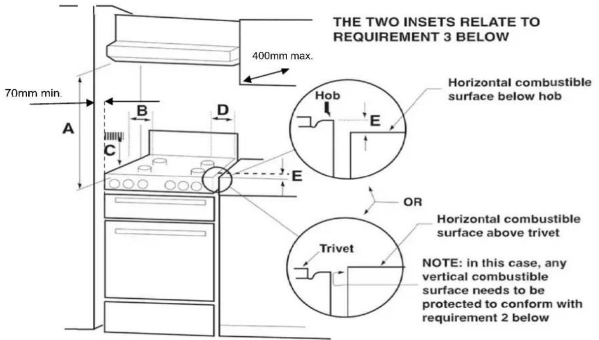
Fig. 01
REQUIREMENTS
1. Overhead clearances – (Measurement A)
Range hoods and exhaust fans shall be installed in accordance with the manufacturer's instructions. However, in no case shall the clearance between the highest part of the hob of the cooking appliance and a range hood or an overhead exhaust fan be less than 700 mm.
Any other downward facing combustible surface less than 700 mm above the highest part of the hob shall be protected for the full width and depth of the cooking surface area in accordance with clause 5.12.1.2. However, in no case shall the clearance to any surface be less than 450mm.
The maximum depth of wall cabinet above the cooking shall be 400 mm.
2. Side clearances – (Measurements B & C)
Where B, measured from the periphery of the nearest burner to any vertical combustible surface, is less than 200 mm, the surface shall be protected in accordance with Clause 5.12.1.2 to a height C of not less than 200 mm above the level of the backguard for the full width of the cooking surface area. Where the cooking appliance is fitted with a "splash back", protection of the rear wall is not required.
The appliance can be installed between two walls. A single sidewall that exceeds the height of the work surface is possible. This must be at a minimum distance of 70 mm from the edge of the cooker.
3. Additional requirements for Freestanding and Elevated Cooking Appliances – (Measurements D & E)
Where D, the distance from the periphery of the nearest burner to a horizontal combustible surface is less than 200 mm, then E shall be 10 mm or more, or the horizontal surface shall be above the trivet. See inserts above.
IMPORTANT INFORMATION FOR INSTALLING AND SERVICING THE APPLIANCE
The cooker can be installed separately, as a freestanding unit, or between kitchen units or between a kitchen unit and the wall.
This appliance is not connected to devices which exhaust combustion products.
Special attention must be focused on the prescriptions described below regarding room aeration and ventilation.
The dimensions of the appliance are listed below:
| LENGTH DEPT | TH HEIGHT | with worktop stamped HEIGHT with | worktop welded |
| 897mm 600mm | adjustable | 870-940mm adjustable 890-960mm |
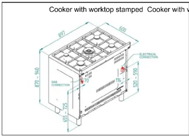
Fig.2
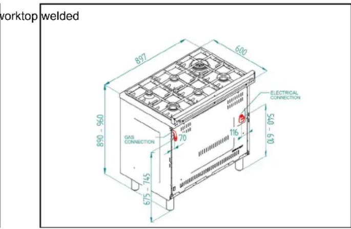
Fig.3
APPLIANCE SERVICING
IMPORTANT!
ALL SERVICING AND MAINTENANCE ARE TO BE COMPLETED BY THE MANUFACTURER'S AUTHORISED PERSONNEL ONLY.
Before carrying any servicing operation disconnect the appliance from gas and electric supply and extra appliance from final installation place in order to have access to the appliance for proper servicing intervention.
STEP 1: PRESSURE REGULATOR.
For NG or ULPG installation ref. to fig. 7 and chapter 'Appliance gas connection' at pag 7
STEP 2: SURFACE BURNERS
For surface burners conversion ref to table 1 chapter ‘Adaption to various types of gas’ at page 8 and chapter ‘Conversion to different types of gas’ at page 12
STEP 3: MAIN OVEN BURNER
For main oven burner conversion ref to table 1 chapter ‘Adaption to various types of gas’ at page 8 and chapter ‘Conversion to different types of gas’ at page 12
STEP 4: VISUAL CHECKS
The following visual check must be performed to ensure that the conversion has been carried out properly and without damage to other components of the range. Verify that the flame of the oven burner be completely blue and with regular aspect as shown below.
CONNECTION OF THERMOCOUPLE TO THERMOSTAT
The thermocouple for oven burner is connected to the magnet. Tight gently the connection.
The tip of the spark plug or thermocouple must fully overlap at least the first gas emission hole of the burner.
After performing all these visual checks, reinstall the bottom panel of the oven compartment and proceed to setting the minimum for each burner.
STEP 5: MINIMUM FLAME ADJUSTMENT
WARNING!
These adjustments should be made only for use of the appliance with Natural gas. For use with ULPG, the bypass screw must be fully turned in a clockwise direction.
Surface burners
Light one burner at a time and set the knob to the MINIMUM position (small flame). Remove the knob.
The range is equipped with a safety valve. Using a small-size slotted screwdriver, locate the choke valve on the valve body and turn the choke screw to the right or left until the burner flame is adjusted to desired minimum.
Make sure that the flame does not go out when switching quickly from the MAXIMUM to the MINIMUM position.
Oven burner
Set the oven temperature control knob to the MAXIMUM setting. Close the oven door and operate the oven for at least 10 minutes. Set the knob to the MINIMUM setting. Remove the knob. With a slotted screwdriver turn the choking screw (by-pass screw at the left side of the thermostat bar) and, while observing the flame at the same time through the bottom oven porthole, evaluate the consistency of the flame so it remains on when switching quickly from MINIMUM to MAXIMUM setting.
Greasing the valves
If it becomes difficult to operate the valve, it should be greased immediately by following the instructions listed below:
1) Disassemble the valve body by loosening the two screws located on the body of valve.
2) Extract and clean the seal cone and its housing with a cloth.
3) Lightly grease the cone with special grease.
4) Insert the cone, moving it several times, remove it again, remove the excess grease and make sure that the gas passage ways are unobstructed.
5) Replace all the pieces by reversing the order in which they were disassembled and check that the valve operates correctly.

natural_image
Line drawing of hands holding small objects, no text or symbols presentRoom Ventilation
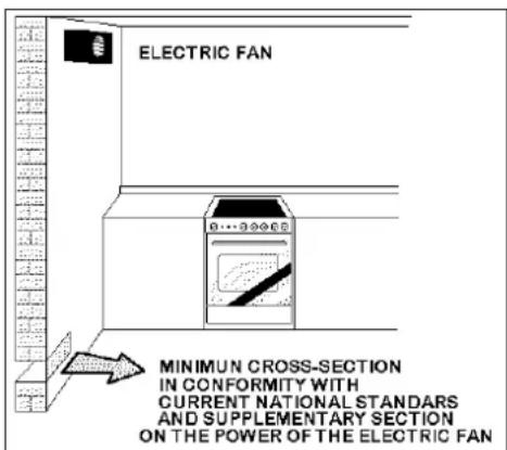
To ensure that the appliance operates correctly, the room where it is installed must be continuously ventilated. The room volume should not be less than 25m3 and the quantity of air should be based on the regular combustion of gas and on the ventilation of the room. Natural air will flow through permanent openings in the walls of the room to be ventilated. These openings will be connected with the outside environment and should have a minimum cross-section defined by current national standards regarding room ventilation (Fig. 04).
These openings should be built so that they cannot be clogged.
Indirect ventilation is also permitted by taking air from the rooms adjacent to the one to be ventilated.

Fig. 04
Location and Aeration
Gas cooking appliances must always evacuate the combustion products by means of hoods connected to chimneys, flues or directly outside (Fig. 05). If a hood cannot be installed It is possible to use a fan installed on a window or directly facing outdoors, to be operated together with the appliance (Fig. 06), provided that there is strict compliance with the ventilation regulations.
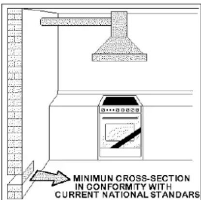
Fig. 05
Fig. 06
APPLIANCE GAS CONNECTION
IMPORTANT: This appliance must be installed by an authorised person.
WARNING: DO NOT MODIFY THIS APPLIANCE
If the appliance cannot be adjusted to perform correctly, contact the service department.
This appliance utilises a threaded 1/2" gas male fitting.
To connect the appliance to the gas network with a flexible hose, a supplemental hose nipple fitting is needed which is supplied with the appliance. (Fig. 07)

natural_image
Line drawings of two door lockers with visible wiring and mounting brackets (no text or symbols)Fig. 07
Gas inlet positions with different leg heights - mm
Gas inlet (mm) - Nat gas Gas inlet (mm) - ULPG
From RH rear side: 70 mm From RH rear side: 70mm
Up from floor cooker with worktop stamped: 655 - 725mm Up from floor cooker with worktop stamped: 570 - 640mm
Up from floor cooker with worktop welded: 675 - 745mm Up from floor cooker with worktop welded: 590 - 660mm
Gas Regulator
The gas connection is via 1/2" tapered thread. Connect the cooker to the gas supply and test for leaks. NEVER use a naked flame to check for gas leaks.
Natural Gas: Gas regulator supplied with the appliance must be installed.
ULPG: Test point adaptor to be fitted and checked at time of installation.
Using a flexible connection
This appliance is approved for connection with a flexible hose, which complies with the AS/NZS 1869 (AGA Approved), 10mm ID, class B or D, between 1-1.2m long. Connection shall be in compliance with AS/NZS 5601.
When installing the hose restraint device, the appliance anchor point is the rear panel.
Using a Copper Pipe connection
We recommend that the isolation valve be fitted prior to the cooker to enable isolation of the cooker from the gas supply.
The valve must be easily accessible at all times.
To find out the gas type factory settings, see label on the rear of the appliance.
TABLE N°1
Adaption to various types of gas
| Burners | Gas type (kPa) | Pressurjector (mm) | Mj/hr | By-pass size (mm) |
| Small | Natural | 1.00 | 0.90 | 4.00 |
| Small | ULPG | 2.75 | 0.54 | 4.00 |
| Medium | Natural | 1.00 | 1.18 | 7.00 |
| Medium | ULPG | 2.75 | 0.70 | 7.00 |
| Large | Natural | 1.00 | 1.55 | 11.50 |
| Large | ULPG | 2.75 | 0.92 | 11.50 |
| Wok | Natural | 1.00 | 1.80 | 14.50 |
| Wok | ULPG | 2.75 | 1.02 | 14.50 |
| Wok 2way | Natural 1.00 | Ex.1.80 int.0.80 | 17.50 | |
| Wok 2way | ULPG 2.75 | Ex. 1.02 int. 0.50 | 17.50 | |
| Oven | Natural | 1.00 | 1.95 | 16.50 |
| Oven | ULPG | 2.75 | 1.10 | 16.50 |
Test the operation of the cooker before leaving
Note: These burners have no aeration adjustment.
Check correct operation of the ignitions system and operation of the regulator and operation of the burners individually and in combination. Burner flames should be clear blue, with no yellow tipping. If the burners show any abnormality check that the burners are correctly located. If satisfactory performance cannot be obtained, contact Bertazzoni Group service.
Important
Before leaving instruct the owner in the use of the cooker it should be expressly noted that we cannot accept any liability for direct or indirect damage caused by wrong connection or improper installation. When being repaired, the appliance must always be disconnected from the mains supply; if required, notify our customer service.
TABLE N°2: GAS BURNER DIMENSION
| Burner | Dimension (mm) |
| Auxiliary | 50 |
| Semi-rapid | 70 |
| Rapid | 95 |
| Wok | 125 |
| Wok 2 ways | 135 |
SUPPORT LEGS AND BACKGUARD INSTALLATION
The cookers are supplied with four transit supports (one for each corner).
Four support legs are supplied separately and are fitted on location to the four corners of the lower support frame. Each support leg is pushed over the relevant transit support until flush with the support frame.
Each leg is adjusted by screwing the lower r section in or out as required for fitting to a 900mm bench height. For lower bench tops adjust the height of the legs to 180mm so the hob is located 10mm above the horizontal combustible surface, ref. AS/NZS 5601.

Fig. 08
Legs should be installed with the appliance close to its final destination, as the legs are not designed for excessive force and will snap off if too much side force is exerted on them (dragging along or angled too much). When fitting, try to keep the appliance as close to a horizontal position as possible. Use of a pallet jack is recommended.
If the legs are not used and the cooker is mounted onto a plinth, four transit supports allow for clearance.
With the legs fitted, the backguard supplied with the appliance can be fitted.
Follow the instructions shown in Fig. 09.
ATTENTION: TAKE CARE DO NOT OBSTRUCT THE OUTLET OPENINGS ON THE BACKGUARD; THEY MUST BE UNOBSTRUCTED FOR PROPER OPERATION

natural_image
Line drawing of a four-gas stove with heat sinks and cabinetry (no text or symbols)
ANTI-TILT DEVICE AND STRAIN RELIEF FLEXIBLE HOSE DEVICE
ANTI-TILTING CHAIN/HOSE RESTRAINING CHAIN
A chain must be fitted by the installer within 50mm of the hose connection point to prevent strain on the hose when the cooker is pulled forward. The chain should restrict the appliance movement to no more than 80% of the hose length. After the chain is installed, check that there is no strain on the hose or gas connections when the cooker is pulled as far forward as the chain allows.
The cooker is also supplied with two chains which are connected to the rear left and right of the appliance. The chains should be connected to the wall directly behind the chains as low as possible to prevent the appliance from tilting forward. If the appliance is installed between two cupboards, drill a hole on each side of the cupboards, pass the chains through the holes and anchor the chains within each cupboard. Ensure the chain connections are strong enough to support the weight of the appliance and taught to prevent it from tilting forward.
WARNING! In order to prevent accidental tipping of the appliance, for example a child climbing onto the open oven door, the stabilising means must be installed. Ensure the chains are correctly anchored to prevent the appliance from tilting forward and to prevent strain on the hose when the cooker is pulled forward.
MAKE SURE THE ANTI-TILTING CHAINS ARE TAUGHT WHEN ANCHORED AND ANTI TILT RESTRAINT IS INSTALLED TO PREVENT THE APPLIANCE TILTING
Please refer to the next two pages for examples of incorrect and correct chain installation.
Accidental tipping
Chains are provided as a preventative measure against accidental tipping.
These chains must be fitted as part of the installers compliance. Failure for your installer to fit chains in accordance with the relevant installation code will make the installation of your upright cooker non-compliant and class an illegal installation.
Incorrect installation
The photographs on this page are of one single kind of incorrect installation (although there are many) which does not have the chains sufficiently secured, figure 1. Shows an example of how far forward an oven can tip when not secured properly. Note: Correct installation is part of the installer compliance.

natural_image
Modern kitchen appliance with open cabin and stainless steel stove (no visible text or symbols)
natural_image
Close-up of a white panel with a red circle highlighting a section, no visible text or symbolsLeft Side of oven, chain not attached
Unfortunately the example on this page is the way many installers are installing uprights. This may believe that they are using the correct method by putting the chain through a hole into the adjacent cabinet and screwing the chain to the back wall but it will not work if not properly.
Putting the chain into the adjacent cabinet is the preferred method, provided there is no slackness in the chain.
Some installations only have a single chain affixed. Both chains must be fixed as part of the installers compliance. Failure to fix both chains will make the installation non compliant
Left Side

In order to prevent the oven from tipping forward as shown on the previous page, we need to make sure both chains provided with the oven are used.
On the left side of the oven a 16mm drill bit was used to drill through the cabinetry into the adjacent cabinet, as you can see the hole has not been drilled hard up against the wall because there is a 16 mm board at the rear of the cabinet. The height of the hole from the floor is level with where the chain attaches to the oven.
The right side has been drilled much the same, a new hole has been drilled below the gas and power supply hole

natural_image
Modern stainless steel electric stove with multiple fumes and control knobs (no visible text or symbols)
Once the holes have been drilled the chains can be fed trough and the upright can be fitted into position.
The chains then need to be pulled as tight as possible from inside the cabinet using a self drilling wood screw. It is better to have the screw fixed closer to the hole for better support. The left and right side examples shown have two extra screws attached to the chain which makes the installation neater by keeping the chain off the shelf away from the gas and electricity supply, they will also provide added support.
At this point the oven will be secured in location and will not move forward at all, it is recommended that all upright oven chains be fitted in this way.
Installation forms part of the installer compliance and that in line with AGA regulations chains are designed to be installed to prevent cooker from tilting. They are not designed to replace parental supervision when the cooker is in use.
WARNING: In order to prevent accidental tipping of the appliance, for example a child climbing onto the open oven door, the stabilising means must be installed. Ensure the chains are correctly anchored to prevent the appliance from tilting forward and to prevent strain on the hose when the cooker is pulled forward.
MAKE SURE THE ANTI-TILTING CHAINS ARE TAUGHT WHEN ANCHORED TO PREVENT THE APPLIANCE TILTING.
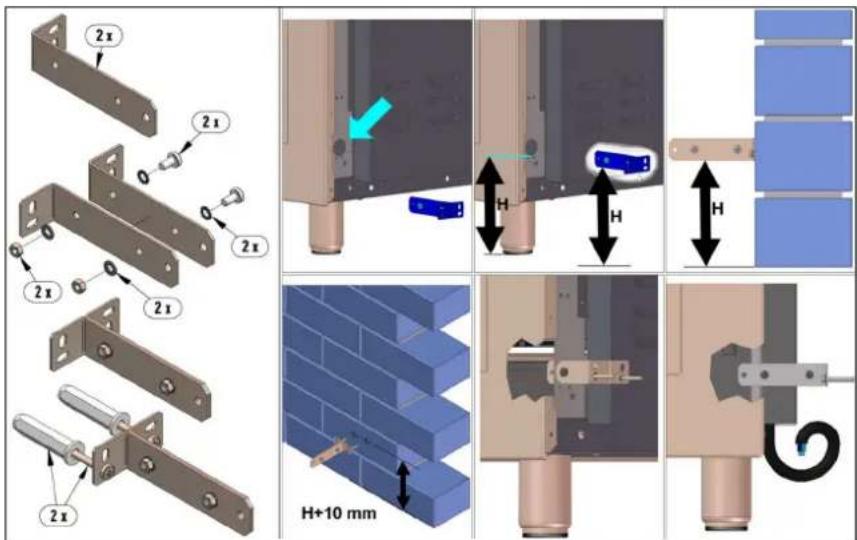
Fig 010
CONVERSION TO DIFFERENT TYPES OF GAS
Before performing any maintenance operation, disconnect the appliance from the gas supply and electricity network.
REPLACING THE NOZZLES TO OPERATE WITH ANOTHER TYPE OF GAS
When converting to ULPG remove the NG gas regulator (if fitted) and fit ULPG test point adaptor.
If converting to Natural Gas, fit gas regulator
Follow the instructions below to change the burner nozzles on the work surface:
1) Pull out the plug from the electric outlet to avoid any type of electric contact.
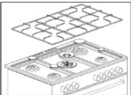
2) Remove the grids from the work surface (Fig. 11).
3) Remove the burners (Fig. 11).
natural_image
Line drawing of a gas stove with a grid-patterned roof and internal components (no text or symbols)Fig. 11 (representation only)
4) Unscrew the nozzles using a 7 mm spanner, and replace them (Fig.12) with those needed for the new type of gas according to what is indicated in the Energy Consumption Table.

natural_image
Technical line drawing of a mechanical assembly with no visible text or symbolsFig.12
5) Burner "MINIMUM" adjustment:
Work surface burner adjustment: follow the instructions below to adjust the work surface burner minimum:
• Light the burner and set the knob to the MINIMUM position (small flame).
- Remove the knob of the valve that is press fit on the rod of that valve.
- For all burners except for the wok burner, insert a small slotted screwdriver into the hole on the valve rod (Fig. 13) and turn the choke screw to the right or left until the burner flame is adjusted to minimum.
- The wok burner has 2 adjustment screws on either side of the body of the valve (Fig. 14). Screw A is for the outer ring and screw B is for the inner ring. Turn the choke screw to the right or left until the burner flame is adjusted to minimum.
- Ensure sure that the flame does not go out when s witching quickly from the MAXIMUM to the MINIMUM position.
Oven burner adjustment: follow the instructions below to adjust the minimum:
- Light the burner setting the knob to the MAXIMUM position.
- Close the oven door and operate the oven for at least 10 minutes.
- Set the knob to the MINIMUM position (corresponding to 120irc ) and then remove it.
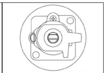
- With a slotted screwdriver turn the choking screw (see figure 15) and, while observing the flame at the same time through the cooker porthole, evaluate the consistency of the flame so it remains on when switching quickly from the MINIMUM to the MAXIMUM position.
WARNING: The above-mentioned adjustment should be made only with natural gas burners, while for those operating with liquid gas the screw must be locked at the end in a clockwise direction.

natural_image
Technical drawing of a mechanical component with concentric circles and a central square (no text or symbols)Fig. 13

natural_image
Technical line drawing of a mechanical component with concentric circles and central hub (no text or symbols)Fig.14
natural_image
Technical line drawing of a mechanical component with central bore and flange (no text or symbols)Fig.15
The electric connection must comply with the current legal standards and regulations.
Before making the connection, check that:
- The system electrical rating and the current outlet are adequate for the maximum power output of the appliance (see the label applied to the bottom of the casing).
- The outlet or the system is equipped with an efficient ground connection in accordance with the current legal standards and regulations. The manufacturer will not be responsible for the non-compliance with these instructions.
- Range with Multifunction Electric oven: The power cord is supplied with a 15A plug, suitable for the load indicated on the label and a standard 15A GPO.
- Range with Gas oven/Electric grill: The power cord is supplied with a 10A plug, suitable for the load indicated on the label and a standard 10A GPO.


Fig. 16
- The power cord must be positioned so that a temperature of 75ircC will not be reached at any point.
- Do not use reductions, adapters or splitters since they might cause false contacts and lead to dangerous overheating.
When the connection is made directly to the electric network:
- Use a device that ensures disconnection from the mains in which the contacts are opened to a distance that permits complete disconnection according to the conditions for over-voltage category III.
- The ground wire must not be interrupted by the circuit-breaker.
- As an alternative, the electric connection can also be protected by a high-sensitivity residual current circuit-breaker but this may be subject to nuisance tripping due to residual humidity in heating elements.
- It is highly recommended to attach the special green-yellow ground wire to an efficient ground system.
WARNING: If the power cord is replaced, the ground wire (yellow-green) connected to the terminal, should be longer than the other wires by about 2 cm.
WARNING: if the supply cord is damaged, it must be replaced by the manufacturer or its service agent or similarly qualified person in order to avoid a hazard.
TABLE N°3: TYPES OF POWER CORDS
| Work surface operation | Oven operation | Cross section |
| 230V ~ | ||
| Only gas burner | Multifunction Electric oven 3x1.5mm 2 | |
| Gas oven/Electric grill 3x1mm 2 | ||
The appliance conforms to the regulation AS/NZS 5263.1.1 regarding gas appliance for domestic use and AS/NZS60335.2.6 regarding safety and CSPR 14 regarding electromagnetic compatibility.
INSTALLATION CHECKLIST
- Is the range mounted on its legs?
- Is the backguard securely connected?
- Has the anti-tip device been properly installed?
- Does the clearance from the side cabinets comply with the manufacturers directions?
- Is the electricity properly grounded?
- Is the gas service line connected following the directions of the manufacturer?
- Have all the proper valves, stoppers and gasket been installed between the range and the service line?
- Has the gas connection been checked for leaks?
- Has the range been set for the type of gas available in the household?
- Is the ignition of all oven burners functioning properly?
- Does the flame appear sharp blue, with no yellow tipping, sooting or flame lifting?
- Has the minimum setting for all burners been adjusted?
- Is the oven ignition working properly?
- Does the oven light work properly?
FINAL PREPARATION
Before using the oven, remove any protective wrap from the stainless steel.
All stainless steel body parts should be wiped with hot, soapy water and with a liquid stainless steel cleanser.
If buildup occurs, do not use steel wool, abrasive cloths, cleaners, or powders! If it is necessary to scrape stainless steel to remove encrusted materials, soak with hot, wet cloths to loosen the material, then use a wood or nylon scraper. Do not use a metal knife, spatula, or any other metal tool to scrape stainless steel! Scratches are almost impossible to remove.
Before using the oven for food preparation, wash the cavity thoroughly with a warm soap and water solution to remove film residues and any dust or debris from installation, then rinse and wiped dry.
APPLIANCE USE AND MAINTENANCE
ATTENTION: Important Warnings.
ATTENTION: ATTENTION: TAKE CARE DO NOT OBSTRUCT THE OUTLET OPENINGS ON THE BACKGUARD; THEY MUST BE UNOBSTRUCTED FOR PROPER OPERATION

natural_image
Line drawing of a four-gas stove with heat sinks and top panel (no text or symbols)• For cookers resting on base
ATTENTION: if the cooker rest on a base, take the measures necessary to prevent the cooker from sliding along the support base.
• For cookers with electric ovens
ATTENTION: The unit becomes hot during use. Do not touch the heating elements inside the oven.
ATTENTION: The accessible parts can become hot during use. Keep children away from the appliance.
- For glass doors
ATTENTION: Do not use harsh abrasive cleaning products or metal spatulas with sharp edges to clean the oven door's glass since this could scratch the surface and the glass could break.
- For gas cooktops
ATTENTION: Clean burner tops and trivets at least once a week, or after any spillage. Gas inlet pipes should be checked periodically for leakages (see section on leak testing), at intervals not exceeding 12 months. Lubrication of valves should only be performed by an authorised person, and is required if the gas control knobs become stiff and difficult to turn.
Do not use steam cleaner to clean the appliance.
WARNING: DO NOT MODIFY THIS
APPLIANCE Please maintain your appliance regularly.
REPLACING PARTS
Before performing any maintenance operations, disconnect the appliance from the g a s supply and electricity network.
To replace parts such as knobs and burners, just remove them from the seats without dis assembling any part of the cooker.
To replace parts such as nozzle supports, valves and electric components follow the procedure described in the burner adjustment paragraph. To replace the valve or the gas thermostat, it is also necessary to disassemble the two rear gas train brackets, loosening the 4 screws (2 per bracket) that attach it to the rest of the cooker and, unscrew the nuts that attach the front burner valves to the control support, after removing all the knobs. To replace the gas or electric thermostat, also disassemble the rear cooker guard, loosening the relative screws, to be able to pull down and reposition the thermostat bulb.
To replace the oven bulb, just unscrew the protection cap that projects out inside the oven (Fig.17)

natural_image
Line drawing of a hand holding a small object with an eye above it, inside a room with shelves (no text or symbols)Fig.17
WARNING: Before replacing the bulb, disconnect the appliance from the electric power supply.
WARNING: The power cord supplied with the appliance is connected to the appliance with an X type connection (in compliance with standards AS/NZS 60335-1, AS/NZS 60335-2-6 and subsequent amendments) for which it can be installed without the use of special tools, with the same type of cord as the one installed.
If the power cord becomes worn or damaged, replace it based on the information reported in table 2. To replace the power cable, lift the terminal board's cover and replace the cable.
CONTROL PANEL DESCRIPTION
On the control panel, small symbols show the function of each knob or key. Here are the several controls that a cooker can have:
Indicates which burner on the gas cooktop a control knob controls, a full square identifying the particular burner.

Indicates the control knob adjusts the functions of the electric oven.

shows the electric thermostat for electric fan oven.

shows the oven fan working button as to allow the oven to operates with fan assisted gas.
The fan operation of the oven prevents the operation of the grill, which therefore cannot be used with the fan in action.

Indicates the control knob adjusts the mechanical timer

shows the ignition key for the oven light (all except the electric fan oven)

shows the push-button for burner ignition
1
shows if keys are in position "on" or "off"
WARNING: If the power is cut off, the cook top burners can be lit with matches. When cooking foods with oil and fat, which are very flammable, the user should not leave the appliance unattended. Do not use sprays near the appliance when it is being used. When using the burners, make sure that the handles of the pots are correctly positioned. Keep children away from the appliance.
OVEN RACKS AND TRAYS
The oven is supplied with a baking tray (with removable wire rack) and wire racks.
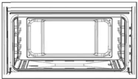
Internally there is a wire support on either side with 5 mounting positions. The racks and tray are designed with a small stop at the back. To insert, push the rack into one of the mounting positions angled down at the front so the stop passes over the front of the support, and then push fully in. To remove, pull the rack out until the stop catches at the front of the support & angle down to fully remove.
USING BURNERS ON COOKTOP
A diagram is etched on the control panel above each knob which indicates which burner corresponds to that knob. Each control knob controls a gas valve and built-in flame safety device.
- Manual lighting (it is always possible even when the power is cut off): Turn the control knob that corresponds to the burner selected anticlockwise, setting it to the MAXIMUM position at the etched star (large flame on the control knob (Fig. 18) and hold a lit match to the burner. Press the knob down and hold for 2 seconds after the burner ignites so the thermocouple heats up. Release the control knob and adjust to the correct setting.
• Electric ignition: Turn the knob that corresponds to the burner selected anticlockwise, setting it to the MAXIMUM position (large flame on the control knob (Fig. 18). Keep pressing the knob down at
this position until the burner ignites, and then wait 2 seconds for the thermocouple to heat up. Release the control knob and adjust to the correct setting.

natural_image
Simple circular diagram with a vertical line, star, and leaf symbols at the bottom (no text or labels)Fig. 18
- -Use of the dual burner (Fig19)
This model controls both the central and external crown of the burner with just one valve.
To ignite the central crown press and turn the knob to the maximum delivery position 1 and hold it down until ignition: in this position the internal flame are at maximum.
Turn the knob to position 2 to have the internal crown at the minimum.
Turn the knob to position 3 to have the internal crown ant the external crown at the maximum.
Turn the knob to position 4 to have the internal crown ant the external crown at the minimum.

Fig.19
Note: It is recommended not to try to ignite a burner if the relative flame cap is not in the correct position.
Tips for using burners correctly:
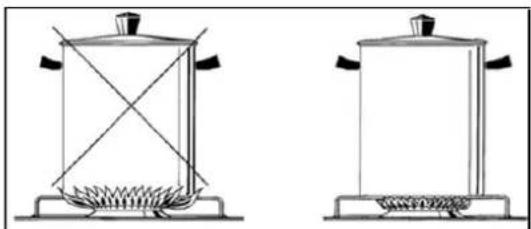
- Use suitably sized pots for each burner (see tab. 4 and Fig. 20).
natural_image
Two simple line drawings of a portable stove with heating elements and a lid, no text or symbols present.Fig. 20
- When the liquid is boiling turn the knob to the MINIMUM position (small flame Fig. 18).
- Use pots with a cover when available.
- Large utensils exceeding the recommended maximum size can cause excessive heat to reflect back onto the appliance, potentially damaging the appliance and causing a temperature hazard.
TABLE N°4 Pan Sizes
| BURNER PAN | DIAMETER recommended (cm) |
| Auxiliary 12-14 | |
| Semi-rapid 14-26 | |
| Rapid 18-26 | |
| Wok 22-26 | |
| Wok 2 ways 22-50 |
ATTENTION: Use Pots with a flat bottom for more efficient heat transfer.
USING THE GAS OVEN
GAS OVEN:
All the gas oven cookers are equipped with a thermostat and safety device to adjust the cooking temperature. The oven temperature is set by turning the knob counterclockwise to match the indicator with the temperature selected. The gas oven can be combined with a gas grill or an electric grill. See the specific pages for use information.
FAN GAS OVEN:
Operating the fan of the oven by means of the appropriate switch situated on the control panel, the circulation of warm air guarantees a uniform heat distribution. The preheating of the oven can be avoided. However for delicate baking, it is preferable to warm the oven before introducing the baking-pan. The baking system with the fan convection changes in part the various traditional baking notions. When roasting meat it is not necessary to turn the meat any more and for a roast on the spit, it is not indispensable to use the spit-roaster, but is sufficient to put the meat directly on the grate.
With the use of the fan gas oven, the baking temperatures are slightly lower of about 10-15°C compared to those in use with the traditional gas oven. The fan operation of the oven prevents the operation of the grill, which therefore cannot be used with the fan in action.
The oven can also be used in a traditional way, (by not activating the fan) for foods requiring heat from the bottom, e.g. pizza.
WARNING: If the burner flames are extinguished accidentally, turn off the control knob and do not try to relight the oven until after at least 1 minute.
TABLE N°6
| THERMOSTAT SETTING TEMPERATURE °C | |
| 1 | 120°C |
| 2 | 140°C |
| 3 | 160°C |
| 4 | 180°C |
| 5 | 200°C |
| 6 | 225°C |
| 7 | 245°C |
| 8 | 270°C |
The oven burner can be ignited in different ways:
- Manual lighting (it is always possible even when the power is cut off):
To light the oven, open the oven door and turn the knob so the no. 8 on the scale matches the indicator (fig.41-42). At the same time put a lit match next to the ignition tube that is visible on the oven level (fig.43). Then press the thermostat knob (this makes the gas start to flow) and keep it pressed, after the burner has been completely lit, for 10 seconds. Release the knob and make sure that the burner remains on, otherwise repeat the operation.
- Electric ignition (only for the models equipped with this device):
In this case, first open the oven door, then press and turn the knob to the maximum temperature setting. Then press the thermostat knob (models with ignition trough knob). Wait about 10 seconds after the burner has been completely lit and then release the knob. Make sure that the burner remains on, otherwise repeat the operation. As for cookers without ignition trough knob, press the thermostat knob and the key with the spark symbol, wait about 10 seconds after the burner has been completely lit and then release the knob. Make sure that the burner remains on, otherwise repeat the operation.
The ignition device should not be used for more than 15 seconds. If after that period the burner still has not been lit, do not use the device and open the door of the room or wait at least 60 seconds before trying to light the oven again.
WARNING: when trying to light the oven, the door must always be open. When using the oven, leave the cooker cover open (if present on your model) to prevent it from overheating.
NOTICE: when using the oven for the first time it should be operated for 15-30 minutes at a temperature of about 250irc without cooking anything inside in order to eliminate any moisture and odours from the internal insulation.
During normal oven use, after lighting the burner and setting the desired temperature, wait about 15 minutes before putting in any food to preheat the oven. The oven is equipped with 5 guides (Fig.44) at different heights
which can be used to insert shelves or the tray. To keep the oven as clean as possible it is recommended to cook meat on the tray or on the shelf that has been inserted inside the tray.
TABLE N°7
| GAS OVEN COOKING TABLE | |||
| TEMP °C HEIGHT MINUTES | |||
| MEAT | |||
| PORK ROAST | 220 (210) 2 60-70 | ||
| BEEF ROAST (YOUNG STEER) | 250 (240) 2 50-60 | ||
| BEEF ROAST | 240 (230) 2 60-70 | ||
| VEAL ROAST | 220 (210) 2 60-70 | ||
| LAMB ROAST | 220 (210) 2 45-55 | ||
| ROAST BEEF | 230 (230) 2 55-65 | ||
| ROAST HARE | 235 (225) 2 40-50 | ||
| ROAST RABBIT | 220 (210) 2 50-60 | ||
| ROAST TURKEY | 235 (225) 2 50-60 | ||
| ROAST GOOSE | 225 (215) 2 60-70 | ||
| ROAST DUCK | 235 (225) 2 45-60 | ||
| ROAST CHICKEN | 235 (225) 2 40-45 | ||
| FISH 200-225 (190-215) 3 15-25 | |||
| PASTRY | |||
| FRUIT PIE 200 (210) 3 35-40 | |||
| TEA CAKE 190 (180) 3 50-55 | |||
| BRIOCHES 175 (165) 3 25-30 | |||
| SPONGE CAKE | 235 (225) 3 | 20 | |
| RING CAKE | 190 (180) 3 30-40 | ||
| SWEET PUFF PASTRIES | 220 (210) 3 | 20 | |
| RAISIN LOAF | 220 (210) 3 15-20 | ||
| STRUDEL | 180 (170) 3 15-20 | ||
| SAVOIA COOKIES | 190 (180) 3 | 15 | |
| APPLE FRITTERS | 220 (210) 3 | 20 | |
| SAZOIARDI SANDWICH | 220 (210) 3 20-30 | ||
| TOAST SANDWICH | 250 (240) 2 | 5 | |
| BREAD | 220 (210) 3 | 30 | |
| PIZZA | 220 (210) 3 | 20 | |
USING THE CHANGE-OVER SWITCH (Fig .21)
The 2+0 change-over switch used for gas oven models with electric grill
the symbol fan.


the symbol

and
is for oven fan and light operation, to use the gas oven or electric grill with
is for turning on the oven light

natural_image
Simple circular diagram with a vertical line and four small icons around it (no text or symbols)Fig.21
USING THE OVEN THERMOSTAT CONTROL KNOB
The thermostat is used to set the maximum internal temperature of the oven. Turn the thermostat control knob clockwise and align the selected temperature indicated on the knob with the index etched on the control panel above it. Thermostat operation is indicated by an orange light which will turn off when the temperature inside the oven is 10irc C greater than the temperature setting, and will turn on when the oven is 10irc C less than the temperature setting. The thermostat can control the oven elements only if an oven function has been set. For electronic timers, the timer must be off (“A” symbol off) or running.
USING THE OVEN FUNCTION CONTROL KNOB (Fig. 22)
The oven function knob is used to control the electric fan and the oven elements in set combinations in conjunction with the timer and thermostat.
The electric oven is heated by 4 elements:
a) Upper element (1200W) and grill element (1500W) combined at the top of the oven cavity.
b) Lower element (1600W) at the bottom of the oven cavity.
c) Two circular elements (1200W) at the rear of the oven cavity, situated around the 2 internal fans.
Select an oven function by turning the oven function control knob so that the symbol for the required function is at the top and in line with the index etched on the control panel above it.
Note: The timer and thermostat must be set correctly for the oven to function.
To turn electric oven off adjust the oven function control knob to position
0 (no function selected). Setting the thermostat control knob to position 0 turns off the elements but it is still possible, using the oven function knob, to turn on the electric fan and the oven light.
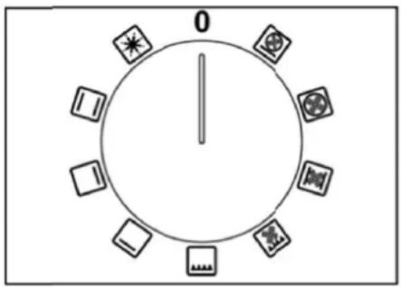
Fig. 22
There are 9 function as per below :

QUICK START/DEFROST FUNCTION: This function runs the rear fans and all elements. The heat generated is too hot to cook in, but is perfect for preheating the oven (run at the required temperature until the thermostat light turns off and on a couple of time, then adjusts to the required function setting. To use as a defrost function, leave the thermostat on 0. This allows air to flow over frozen food speeding up defrost times.
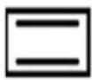
CONVENTIONAL COOKING FUNCTION: This function runs the upper and lower elements. It is dependent on the timer and the thermostat setting.
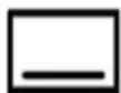
LOWER ELEMENT COOKING FUNCTION: This function runs the lower element. It is dependent on the timer and the thermostat setting. It can be used at low temperatures, for slow cooking casseroles & custard, and at high temperatures for pastries.

UPPER ELEMENT COOKING FUNCTION: This function runs the upper element. It is dependent on the timer and the thermostat setting. With less power than the grill, this can be used to brown cauliflower cheese and to reheat lasagne.

GRILL COOKING FUNCTION: This function runs the upper and grill elements. It is dependent on the timer and the thermostat setting. Best used for shorter grilling times, like toast or crumpets.

GRILL AND FAN COOKING FUNCTION: This function runs the upper and grills elements, and runs both rear internal fans. It is dependent on the timer and the thermostat setting. Best
used for longer grilling times, or when grilling foods with a lot of moisture.

FAN ASSIST COOKING FUNCTION: This function runs the upper and lower elements, and runs both rear internal fans. It is dependent on the timer and the thermostat setting. Best used when cooking large amounts of food at one time, for frozen potato products and ttered chicken or fish.

FAN OVEN COOKING FUNCTION: This function runs the circular rear elements; and runs both rear internal fans. It is dependent on the timer and the thermostat setting. This function is suitable to most types of cooking, with even temperatures throughout the
oven.

PIZZA COOKING FUNCTION: This function runs the lower and circular rear elements, and runs both rear internal fans. It is dependent on the timer and the thermostat setting. Great for Pizza s, pastries or flat breads, where you want the base crispy and the rest cooked.
USING THE ELECTRIC OVEN
When using the oven for the first time it should be operated for a maximum of 30 minutes at a temperature of about 250irc C to eliminate any odours generated by the internal insulation. During normal oven use, select the desired cooking temperature using the thermostat knob and wait until the orange light turns off (set temperature has been reached) before putting in any food. The oven is equipped with 5 guides at different heights (Fig. 23) which can be used to insert shelves or the tray. To keep the oven as clean as possible it is recommended to cook meat on the tray or on the shelf that has been inserted inside the tray. Always turn the oven off by adjusting the oven function control knob to off (0).
NOTE: After use, the cooling fan will continue to run until the internal electrical system has cooled sufficiently.
natural_image
Technical line drawing of a rectangular frame with internal compartments and dimension annotations (no readable text or symbols)Fig. 23
When cooking, always open the oven door slightly first (head away from the door), to allow any built-up steam to escape, and then open fully. Always use heat resistant gloves when removing hot items from the oven. Never line the sides or base of the oven, or enamel backing dishes with aluminium foil (it can damage the enamel surface). Never cook or place cookware on the base – always use trays and shelves provided. Always preheat your oven before cooking (see the quick start function), which allows more accurate timing of cooking.
conventional cooking
Conventional cooking cooks with heat coming from both the top and bottom, ideal for roasts and pastries. After preheating oven to the correct temperature ( 50irc C to 250irc C), adjust oven function control knob to conventional cooking and place food inside oven. Set timer if needed.
fan oven cooking
Fan Oven cooking cooks with heat coming from the rear of the oven, with hot air circulated around by the fans, ideal for cooking different types of food together without mixing the tastes. Pre-heat the oven for 10
minutes before inserting the trays. Adjust oven function control knob to fan oven cooking and place food inside oven. Set timer if needed.
grilling
The grill is controlled using the oven's temperature knob. The grill function uses both elements at the top of the oven, so is faster and more powerful than using the top element alone. Run this function with the door closed and at a temperature not exceeding 150irc C for up to 15 minutes. Use the enamel tray with wire rack insert at positions 1 or 2 (or lower to slow down the grilling process). Do not leave the tray in the upper positions when not in use, as they will deflect heat away from food.
Preheat for 5 minutes first before adding the food and tray. This function is best for thinner, quickly cooked food like toast; for thicker food that will take longer, use the grill and fan cooking function.
grilling with fans
This function is similar to the grilling function, but with the rear fans added, allowing a more even heat to flow around the food. Run this function with the door closed. Place the food on a wire rack and insert at position 3. Place a baking dish on level 5 to catch any juice or crumbs (this allows the heat to circulate the food). This is better for thicker foods which need to be cooked for longer times. Preheat for 5 minutes first before adding the food and tray.
USING THE MINUTE-MINDER (fig.24)
The minute-minder advises the user, with an acoustic signal, when food has been cooked, after a certain time period has elapsed. To use the device, wind the minute-minder by turning the knob clockwise one complete turn. Then turn the knob counterclockwise so that the indicator corresponds with the selected cooking time
WARNING: the acoustic signal does not stop the cooking cycle. The use must turn off the cooking cycle by hand using the relative knobs.

Fig 24
USING THE END OF COOKING TIMER (fig 25)
It allows to select the cooking time manually or timer with automatic shut off of the oven at the end of cooking.
If not cooking time is selected, it is necessary to position the timer knob on the symbol 🎨. To turn off the oven, select the timer knob on the desired cooking time and set the function and the temperature knobs; the end of the countdown will be confirmed with a repeating tone.

Fig.25
NOTE: This function is available for the electric oven only.
USING THE DIGITAL CLOCK (fig.26)
Power on
Display is flashing
Time of day function
3 button version: press time of day button
2 button version: press both button simultaneous
Set time of day with "+" and "-" buttons.
This function remains activated 7 seconds after the last "+" / "-" operation!
Change Summertime / Wintertime
Activate time of day function; press the button for 4 seconds until the hours display will flash. Change the hours only by using the "+" or "-" button. The minutes and hidden seconds will not be affected!

This function will be activated with "+" button. Press "+" button again to increase duration time.
During setting the units are 10 seconds steps or minutes.
During count down the timer has priority in the display. The bell- symbol illuminated. The units are seconds or minutes in the long time section.
The maximum time is 10 h. The format change will happen after 99 minutes and 50 seconds to 1 hour and 40 minutes.
The pot- symbol illuminated.
To show time of day press "time of day" button for 6 seconds.
Reset timer
Count down to zero with permanent pressing “-” button. (automatic stop at zero)
Signal
The signal after "time out" will stay 7 minutes if it has not been reset with "time of day" button.
The following signal will be skipped if time of day is pressed during the last 15 seconds of the timer.
Signal frequency
If no function is activated, the signal frequency can be selected by pressing the "-" button.
Three different frequencies (1,5; 2,0; 3,0kHz) are selectable.
USING THE TOUCH CLOCK (fig.27)
Mains frequency detection
At power on mains frequency is determined. When the timer is connected to 60Hz,
the Celsius symbol is flashing during start-up.
Power On
At power on, the relay contact is opened. The display and AUTO symbol flashes and time of day starts from 0:00. Power on state with flashing daytime remains until time of day is set.
Setting Time of Day
Press PLUS and MINUS button simultaneously. At Power On, also MODE button is possible.
Time of day can be set with PLUS or MINUS, while the colon between hours and minutes is flashing.
Quick setting mode starts when PLUS or MINUS is held for more than 1 second. If daytime setting mode is selected while an automatic program is active, the automatic program is cancelled.
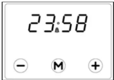
Fig.27
The Buzzer
The buzzer interval alarm signal sounds if minute minder has reached the end time. The signal can be switched off by pressing any key or by passing the signal duration limit.
Changing the Buzzer frequency
First press Plus and Minus simultaneously (menu far editing the time) and then Mode for selecting the menu far changing the buzzer frequency. While the text is visible the buzzer signal frequency can be changed by touching Minus repetitively.
Note: If the touch pad is inactive, a visual alarm will only be reset when a valid key combination is pressed far more than 2 seconds.
Clearing Programs and Manual function
The duration of the minute minder can be cleared by
a) "clear Function": First select minute minder program, then press PLUS and MINUS button simultaneously.
after this clear the display returns from adjustment mode to time of day immediately.
b) Back counting of duration to zero. The timer remains in adjustment mode.
Minute Minder
While minute minder mode is selected, the Bell symbol flashes and the display reads the remaining time in hours and minutes, only if the last minute is counting down the remaining seconds are displayed. An active minute minder program is indicated by the statically illuminated Bell symbol. If alarm time has finished, an acoustic interval signal sounds and the Bell symbol flashes.
The minute minder program runs independently of other programs.
Key Lock
After power on reset or when no key is pressed for 7 seconds, the key look function is activated. Pressing a valid key or key combination for 2 seconds or more will deactivate the key lock.
USING THE ANALOG CLOCK (fig.28)
For setting up the time displayed by watch pointers push briefly twice the knob till getting the CLOCK icon flashing.
For increasing or decreasing time displayed 1 minute by 1, turn the knob clockwise or counterclockwise, le minutes pointer will increase or decrease 1 minute by minute clockwise or counterclockwise.10 seconds after last set up the electronic timer will exit time set up mode.Minute minder set up will activate a simple alarm when set up time is over.
For setting up an alarm push briefly once the knob till getting ALARM icon flashing. The turn the knob, set up the alarm time and briefly push once the knob to confirm; Alarm Icon will stay on for all the set up time. When set up time is over an acoustic buzz will be activated. Push again briefly once the knob for going back to time display. For cancelling minute minder set up keep the knob pushed until ALARM icon goes off.

Fig.28
USING THE ELECTRONIC TIMER (fig.29)
Selecting and adjusting timer functions
Select a timer function by pressing the function button and set the required time with the +/- buttons.
Pressing the "+" button increases the time set, pressing "-" decreases it. The count-up and count down speed increases the longer the button is held in the appropriate position.
Manual operation
The oven needs to be put into manual mode to operate without the timer. Press duration and end time button together. This will allow the oven to bypass the timer and run manually. The "A" symbol will be erased and the pot symbol illuminated. Any program which has been set is cancelled.
Setting the time of day
Select the function by pressing the duration and end buttons together, and then adjust the time of day with the +/- buttons.
Fig.29

Semi-automatic operation with cooking duration
Select the desired cooking function and temperatures using the oven control knobs. Press the duration button and set the required duration with the +/- buttons. The "A" and cook pot symbols appear and the oven becomes active. When the time has been reached, the oven and the cook pot symbol are turned off. An audible signal sounds and the symbol "A" will begin to flash. Reset the oven to off using the oven control knob and press any of the 3 buttons to the left to stop the audible sound.
Semi-automatic operation with cooking end time
Select the desired cooking function and temperatures using the oven control knobs. Press the end button and set the required end time with t h e +/- buttons. The "A" and cook pot symbols appear and the oven becomes active. When the end time has been reached, the oven and the cook pot symbol are turned off. An audible signal sounds and the symbol "A" will begin to flash. Reset the oven to off using the oven control knob and press any of the 3 buttons to the left to stop the audible sound.
Fully automatic operation
Select the desired cooking function and temperatures using the oven control knobs. Press the duration button and set the required cooking duration with the +/- buttons. The "A" and cook pot symbols appear and the oven becomes active. Press the end button (the earliest end time will be displayed) and set the required end time with the +/- buttons. The oven and the cook pot symbol will both turn off.
When the start time is reached (end time – duration), the cook pot symbol appears again and the oven becomes active. When the end time has been reached, the oven and the cook pot symbol are turned off. An audible signal sounds and the symbol "A" will begin to flash. Reset the oven to off using the oven control knob and press any of the 3 buttons to the left to stop the audible sound.
Minute minder
Press the minute minder button and set required time with the +/- buttons. While the function is running, the bell symbol is displayed. When the time set has elapsed, the audible signal sounds. Press any of the 3 buttons to the left to stop the audible sound.
Audible signal
The audible signal sounds at the end of a minute minder cycle or of a cooking program for a period of 7 minutes (unless stopped by pressing one of the 3 buttons to the left). The sound can be adjusted by pressing the "-"button with no other function selected. There are 3 different sounds to choose from.
Timer function verification
A function which has been set is carried out after setting the time required. The “time to run” can be verified at any point by pressing the appropriate function button.
Cancelling timer functions
A program can be cancelled by selecting the manual function. When a program finishes, it is automatically cancel.
USING THE 3 KEYS ELECTRONIC PROGRAMMER (fig.30)
The first start up
The numbers and the A letter on the display are blinking when the oven is switched on for the first time, or after a power cut: the appliance cannot be operated in this condition.
To set the hour and/or to enable the appliance to operate press the M key for at least 2 seconds: the A letter turns off and the numbers now are steady on the display.
The dot (3) starts blinking: press the - or + key to set the hour.
The hour is accepted by the programmer just few second after having released the key.
N.B. the appliance can be correctly used for coking only when you will see on the display the symbol (2).

Fig.30
| The | A* | Automatic programmer is working. (* in some models there is the writing 'Auto' instead of A). |
| 2 | The appliance is ready for manual use (not automatic). | |
| 3 | • | When blinking, the programmer is in setting hour mode. |
| 4 | Timer set. | |
| 5 | Decreasing numbers when setting the timer.Also for choose your desired sound level ( 3 levels available). | |
| 6 | M | "Mode" kev to access the programming options of the programme. |
| 7 | + | Increasing numbers when setting the timer. |
Timer
The purpose of the timer is just of a sound signal, which can be set for a max time of 23h59min. once elapsed the set time, the (4) symbol turns off and a sound signal is heard; this sound set off automatically in 7min, or you can stop it by pressing any key of the programmer. To set the timer press the M key for 2 seconds, or anyway just to see the (4) symbol blinking. Set the timer by using the + or - keys. Release the + or - key when you have matched your desired time. In a few seconds the current time appears on the display together with the ) symbol. The countdown starts immediately from now on.
Semi-automatic cooking
Cooking time: Once having selected a coking function and set the desired temperature, press the M key for a 2 seconds time to access the programming mode. The (4) symbol appears. Release and press again the M key. On the display, the A symbol starts blinking and the "dur" writing appears on the display, then it changes to O'00. Set the cooking time with the - or + keys. (max available time:
10h). The selected time is automatically processed by the programmer in a few seconds, or you can also touch the M key many times just to see again the current time.
The A and (2) symbols will be on the display. Once the set cooking time is finished, a sound will be heard and the oven automatically switches off. Please see the following paragraphs about how to disable the sound alarm and restarting the oven.
End of cooking
once having selected a cooking function and set the desired temperature, touch the M key to access the programming mode for at least 2 sec. the ) symbol switches on. Release and touch again the M key.
On the display the A symbol starts blinking and the writing "dur" appears. Touch again the M key. On the display the writing "End" appears. The last one changes few seconds after with the symbol 0·00.
Set the end of cooking time with the keys - or +. (maximum available time: 10hOOm).
The selected time is automatically processed by the programmer in a few seconds, or you can also touch the M key many times just to see again the current time.
The cooking immediately starts, while on the programmer display the current time is shown again in a few seconds. The A and (2) symbols will be on the display.
Once the set end of cooking time is finished, a sound will be heard and the oven automatically switches off. Please see the following paragraphs about how to disable the sound alarm and restarting the oven.
Automatic cooking
Set a cooking time following the instructions on the cooking time paragraph, then set the end of cooking time following the instructions on the previous paragraph. (Max available end of cooking time 24h). The oven automatically switches on at a determined time which is the difference between the end of cooking time and the cooking time.
During the waiting time before cooking, which goes from the oven start to the heating, on the display appears the A symbol to show that an automatic program is on and the current time. The oven on is marked by the (2) symbol. Once the set end of cooking time is finished, a sound will be heard and the oven automatically switches off.
Please see the following paragraphs about how to disable the alarm and restarting the oven.
How to disable the sound alarm: To disable the sound just touch one of the keys.
Operating again the oven
Once a semi-automatic or automatic cooking has expired, on the display appear the current time and the blinking A symbol. In this condition, the heating elements and the light bulb of the oven are disabled. To enable again the oven, just touch and keep the M key up to see the symbol (2) on the display and the A symbol disappears.
OTHER FUNCTIONS
How to delete a cooking time (semi-automatic or Automatic)
To delete a semi-automatic or automatic cooking program, with the A symbol on, touch together the - and + keys for at least 2 seconds or anyway up to see the (2) and the disabling of A symbol.
How to delete the countdown timer
To delete the counting of the timer, which symbol is ) t touch the M key for at least 2 seconds or anyway up to see the ) symbol blinking. Touch together the - and + keys.
Checking the function settings
The set or remaining time of every cooking function of the programmer can be recalled to the display by entering in program mode with the M key. Touch and keep the M key for almost 2 seconds or anyway up to see the (4) symbol. The remaining time appears on the display, or a series of zero numbers if the timer is disabled. Touch again the M key. On the display appears the "dur" writing, then alternately the remaining time or a series of zero number (disable timer).
By touching again the M key, the end of cooking time appears together with the "End" writing.
How to change the current time or the sound level
With the programmer in standard mode, the (2) symbol is on, touch together the - and+ keys for at least 2 seconds or anyway up to see the dot (3) blinking.
To update the hour on the display: touch the + or - keys.
To change the sound level: touch the M key. On the display appears the writing: Ton.. followed by a number. Select with the - key your favourite sound level.
Note: number 1 is referred to the highest sound level. The available levels are 3.
Attention: Power cut causes the loss of any program, even the clock; that means the programmer will have to be set again.
USING THE THERMOMETER (fig.31)
The cooker is fitted with a device to measure the temperature in the middle of the oven.
This lets you check the temperature inside the oven and adjust food cooking temperatures more accurately.
Electric oven
When you turn on the oven, the orange light comes on to indicate that the heating elements are working: The thermometer dial will start to move towards the set temperature. The orange light will keeping coming on and off, indicating that the heating elements are working to maintain the temperature inside the oven. The light may go off for a few minutes

Fig.31
before the thermometer has reached the temperature required. This is normal, because operation of the heating elements is regulated so that heat is distributed properly inside the oven. Heat is optimally distributed inside the oven when the thermometer dial has stopped. If the oven temperature drops or goes up, the thermometer dial will follow these variations in the same way. When the oven is turned off, the temperature on the thermometer will slowly drop until it reaches room temperature.
NOTE: The temperatures on the knob are indicative. Follow the thermometer temperature for cooking.
Gas oven
When the oven is turned on, the burner will start working at the maximum and the thermometer dial will start to move towards the set temperature. The flame may die down before the thermometer has reached the temperature required. This is because burner power is reduced so that heat can be evenly distributed inside the oven. Heat is optimally distributed inside the oven when the thermometer dial has stopped. When the oven is turned off, the temperature on the thermometer will slowly drop until it reaches room temperature.
NOTE: The Thermostat Position and Oven Temperature correspondence in table no. 5 is indicative and depends on various factors such as the type of gas and supply pressure. Follow the thermometer temperature for cooking.
NOTE: it is normal to record different temperatures from those indicated on the panel thermometer, when you measure the temperature in the middle of the oven using a different thermometer. The temperature indicated by the thermometer is the mean temperature inside the oven and does not indicate the temperature of any single point.
USING THE SELF-CLEANING OVEN
On models which have this device, the self-cleaning oven differs from normal ovens because the inner surfaces are coated with a special micro-porous enamel that absorbs and eliminates grease residues during cooking. If liquid grease is released, self-cleaning is not sufficient, so wipe the grease stains with a damp sponge and then heat the oven to the maximum temperature, wait for it to cool down and wipe again with a damp sponge.
CLEANING THE APPLIANCE
Before cleaning the appliance, it should be disconnected from the power supply and turned off the main gas feeder valve.
Cleaning the work surface
Periodically clean the burner parts and trivets as listed below. Note that all parts must be thoroughly rinsed and dried before being replaced.
Any liquid that overflows from pots must always be removed using a rag.
If it becomes difficult to open or close a valve, do not force it, but immediately contact the Bertazzoni Group service department.
Cleaning the enamelled parts
The trivets and burner covers are cast iron with an enamel coating. To maintain the original features of the enamelled parts they should be cleaned frequently with soapy water. Never use abrasive powders. Do note leave acidic or alkaline substances on the enamelled parts (vinegar, lemon juice, salt, tomato sauce, etc.) and do not wash the enamelled parts while they are still hot.
Cleaning the STAINLESS steel parts
Clean the parts with soapy water and then dry them with a soft cloth. The shine is maintained by periodically using special products that generally are found in the market. Never use abrasive powders.
Cleaning the burner bodies
The aluminium burner bodies sit on the burner bases. Remove from the base and wash them with soapy water. Rinse and dry, and check that all holes and slots are fully cleaned. Replace on the burner bases, taking care that they are positioned and orientated correctly.
Cleaning the inside of the oven
To thoroughly clean the inside of the oven, it is recommended that the door be removed first. First lock the hinge in place with the nail supplied (01-02). With the hinges fixed, grab both sides of the door and slowly work the door off the hinges towards you. Once fully removed, place in a safe position until it is time to fix back in place (in the opposite order). The internal rack guides can also be temporarily removed by undoing the screws holding them in place and lifting out.
TROUBLESHOOTING
If you have a problem with your appliance, check the following before contacting service.
| PROBLEM | SOLUTION |
| Oven or hob not working | Check the electricity is turned on.Check your fuses. If the fuse continues to blow, call Bertazzoni Group service.Check the circuit breaker.Ensure correct knob is positioned correctly.Dry or clean ignition electrodes.Make sure flame ports and ignition areas are clean and dry.Check gas main supply is on.Ensure cap/crown correctly fitted.Replace or tighten light globes. |
| Heating up problems | Oven not pre-heated: Pre-heat oven for 10 minutes.Check oven door is closed properly.Remove foil or trays from bottom of oven.Change oven temperature.Pre-heat oven before putting the food in to be cooked. |
| Unit smoking/odours | Turn the oven on high to remove protective oils.Persistent gas smell: do not operate the cooker call Bertazzoni Group service. |
| Condensation note: some Condensation is normal and is to be expected during cooking. | Reduce the amount of water used for cooking.Leave the door open after cooking if food remains in cooker for warming. |
| Oven shelves are tight | Remove oven shelf and re-insert. |
| Cooling fan runs after ovens turns off | This is normal and not a fault. |
DISPOSAL INFORMATION
Most of the packing materials are recyclable. Please dispose of those materials through your local recycling depot or by placing them in appropriate collection containers.
If you wish to discard this product, please contact your local authorities and ask for the correct method of disposal.
APPLY WIRING DIAGRAM LABELS
BERTAZZONI AUSTRALIA Pty Ltd
ABN 91 623 588 027
PO Box 5317 South Melbourne, Victoria 3205
Contact number 1800 65 42 65
Email: customercare.au@bertazzoni.com



- INSTALLATION, MAINTENANCE AND USE INSTRUCTIONS FOR FREE-STANDING COOKERS 90x60 cm GIANT OVEN
- THIS APPLIANCE HAS BEEN DESIGNED FOR DOMESTIC USE ONLY TO BE INSTALLED BY AN AUTHORISED PERSON
- WARNINGS:
- REQUIREMENTS
- Overhead clearances – (Measurement A)
- Side clearances – (Measurements B & C)
- Additional requirements for Freestanding and Elevated Cooking Appliances – (Measurements D & E)
- IMPORTANT INFORMATION FOR INSTALLING AND SERVICING THE APPLIANCE
- APPLIANCE SERVICING
- IMPORTANT!
- STEP 1: PRESSURE REGULATOR.
- STEP 2: SURFACE BURNERS
- STEP 3: MAIN OVEN BURNER
- STEP 4: VISUAL CHECKS
- CONNECTION OF THERMOCOUPLE TO THERMOSTAT
- STEP 5: MINIMUM FLAME ADJUSTMENT
- WARNING!
- Surface burners
- Oven burner
- Greasing the valves
- Room Ventilation
- Location and Aeration
- APPLIANCE GAS CONNECTION
- WARNING: DO NOT MODIFY THIS APPLIANCE
- Gas inlet positions with different leg heights - mm
- Gas inlet (mm) - Nat gas Gas inlet (mm) - ULPG
- Gas Regulator
- Using a flexible connection
- Using a Copper Pipe connection
- Test the operation of the cooker before leaving
- Important
- SUPPORT LEGS AND BACKGUARD INSTALLATION
- ANTI-TILT DEVICE AND STRAIN RELIEF FLEXIBLE HOSE DEVICE
- ANTI-TILTING CHAIN/HOSE RESTRAINING CHAIN
- Accidental tipping
- Incorrect installation
- CONVERSION TO DIFFERENT TYPES OF GAS
- REPLACING THE NOZZLES TO OPERATE WITH ANOTHER TYPE OF GAS
- When the connection is made directly to the electric network:
- INSTALLATION CHECKLIST
- FINAL PREPARATION
- APPLIANCE USE AND MAINTENANCE
- REPLACING PARTS
- CONTROL PANEL DESCRIPTION
- OVEN RACKS AND TRAYS
- USING BURNERS ON COOKTOP
- - -Use of the dual burner (Fig19)
- Tips for using burners correctly:
- USING THE GAS OVEN
- GAS OVEN:
- FAN GAS OVEN:
- USING THE CHANGE-OVER SWITCH (Fig .21)
- USING THE OVEN THERMOSTAT CONTROL KNOB
- USING THE OVEN FUNCTION CONTROL KNOB (Fig. 22)
- There are 9 function as per below :
- USING THE ELECTRIC OVEN
- conventional cooking
- fan oven cooking
- grilling
- grilling with fans
- USING THE MINUTE-MINDER (fig.24)
- USING THE END OF COOKING TIMER (fig 25)
- USING THE DIGITAL CLOCK (fig.26)
- Power on
- Time of day function
- Change Summertime / Wintertime
- Reset timer
- Signal
- Signal frequency
- USING THE TOUCH CLOCK (fig.27)
- Mains frequency detection
- Setting Time of Day
- The Buzzer
- Changing the Buzzer frequency
- Clearing Programs and Manual function
- Minute Minder
- Key Lock
- USING THE ANALOG CLOCK (fig.28)
- USING THE ELECTRONIC TIMER (fig.29)
- Selecting and adjusting timer functions
- Manual operation
- Setting the time of day
- Semi-automatic operation with cooking duration
- Semi-automatic operation with cooking end time
- Fully automatic operation
- Audible signal
- Timer function verification
- Cancelling timer functions
- USING THE 3 KEYS ELECTRONIC PROGRAMMER (fig.30)
- The first start up
- Timer
- Semi-automatic cooking
- End of cooking
- Automatic cooking
- Operating again the oven
- OTHER FUNCTIONS
- How to delete the countdown timer
- Checking the function settings
- How to change the current time or the sound level
- USING THE THERMOMETER (fig.31)
- Electric oven
- Gas oven
- USING THE SELF-CLEANING OVEN
- CLEANING THE APPLIANCE
- Cleaning the work surface
- Cleaning the enamelled parts
- Cleaning the STAINLESS steel parts
- Cleaning the burner bodies
- Cleaning the inside of the oven
- TROUBLESHOOTING
- DISPOSAL INFORMATION
- APPLY WIRING DIAGRAM LABELS
Brand : LA GERMANIA
Model : TUS96C71BX
Category : Oven