3130 - Uncategorized FLUKE - Free user manual and instructions
Find the device manual for free 3130 FLUKE in PDF.


| Product Type | Portable Pressure Calibrator |
| Brand | Fluke |
| Model | 3130 |
| Dimensions (H x W x D) | 387 x 305 x 178 mm (15.3 x 12.0 x 7.0 in) |
| Weight | ~7.0 kg (15.5 lb) |
| Power Supply | 16 V dc universal adapter/charger (90 V ac to 250 V ac input) |
| Battery | Internal high-capacity NiMH, 3800 mAhr |
| Battery Life (fully charged) | Approximately 50 hours (measurement only or with external pressure supply); pump cycles: 125 to 20 bar, 300 to 10 bar, 1000 to 2 bar |
| Pressure Range (internal pump) | -12 psi to 300 psi (-0.8 bar to 20 bar) |
| Pressure Accuracy (1 year) | 0.025% of reading ± 0.01% FS |
| Pressure Units | psi, bar, mbar, kPa, MPa, kg/cm², mmH₂O (4°C), mmH₂O (20°C), cmH₂O (4°C), cmH₂O (20°C), inH₂O (4°C), inH₂O (60°F), inHg (0°C), mmHg (0°C) |
| mA Measure Range | 0 mA to 24.000 mA |
| mA Measure Accuracy | 0.015% of reading ± 0.002 mA |
| mA Source Range | 0 mA to 24.000 mA |
| Voltage Measure Range | 0 V to 30.000 V dc |
| Voltage Measure Accuracy | 0.015% of reading ± 0.002 V |
| Loop Power | 24 V dc (23 V to 28 V) for mA or voltage transmitters |
| Display | Up to three process measurement sections with menu bar, backlit |
| Media Compatibility | Clean, dry, non-corrosive gas only |
| Operating Temperature | -10 °C to +50 °C (14 °F to 122 °F) |
| Humidity | 10% to 95% RH, non-condensing |
| Safety Standards | IEC 61010-1, 30 V max, Pollution Degree 2 |
| Remote Interface | RS-232 (9600 baud, 8 data bits, 1 stop bit, no parity, Xon/Xoff) |
| Included Accessories | Printed safety info, manual CD, 6 quick connectors, 2 hoses (3 ft), 2 fittings, thread seal tape, test cables (2 red, 2 black), universal power supply, traceable calibration certificate |
| Key Functions | Pressure measurement, mA measure/source/simulate, voltage measure, switch test, transmitter calibration, %-error, min/max, damping, HART resistor (250 Ω), pump limit, zero, save/recall setups, auto shutdown, contrast adjustment |
| Maintenance | Clean with soft cloth dampened with water or mild soap; use only Fluke approved power adapters; replaceable parts: test cables, ac adapter/charger, filter pack |
Frequently Asked Questions - 3130 FLUKE
User questions about 3130 FLUKE
0 question about this device. Answer the ones you know or ask your own.
Ask a new question about this device
Download the instructions for your Uncategorized in PDF format for free! Find your manual 3130 - FLUKE and take your electronic device back in hand. On this page are published all the documents necessary for the use of your device. 3130 by FLUKE.
USER MANUAL 3130 FLUKE
Portable Pressure Calibrator
Users Manual
LIMITED WARRANTY AND LIMITATION OF LIABILITY
Each Fluke product is warranted to be free from defects in material and workmanship under normal use and service. The warranty period is one year and begins on the date of shipment. Parts, product repairs, and services are warranted for 90 days. This warranty extends only to the original buyer or end-user customer of a Fluke authorized reseller, and does not apply to fuses, disposable batteries, or to any product which, in Fluke's opinion, has been misused, altered, neglected, contaminated, or damaged by accident or abnormal conditions of operation or handling. Fluke warrants that software will operate substantially in accordance with its functional specifications for 90 days and that it has been properly recorded on non-defective media. Fluke does not warrant that software will be error free or operate without interruption.
Fluke authorized resellers shall extend this warranty on new and unused products to end-user customers only but have no authority to extend a greater or different warranty on behalf of Fluke. Warranty support is available only if product is purchased through a Fluke authorized sales outlet or Buyer has paid the applicable international price. Fluke reserves the right to invoice Buyer for importation costs of repair/replacement parts when product purchased in one country is submitted for repair in another country.
Fluke's warranty obligation is limited, at Fluke's option, to refund of the purchase price, free of charge repair, or replacement of a defective product which is returned to a Fluke authorized service center within the warranty period.
To obtain warranty service, contact your nearest Fluke authorized service center to obtain return authorization information, then send the product to that service center, with a description of the difficulty, postage and insurance prepaid (FOB Destination). Fluke assumes no risk for damage in transit. Following warranty repair, the product will be returned to Buyer, transportation prepaid (FOB Destination). If Fluke determines that failure was caused by neglect, misuse, contamination, alteration, accident, or abnormal condition of operation or handling, including overvoltage failures caused by use outside the product's specified rating, or normal wear and tear of mechanical components, Fluke will provide an estimate of repair costs and obtain authorization before commencing the work. Following repair, the product will be returned to the Buyer transportation prepaid and the Buyer will be billed for the repair and return transportation charges (FOB Shipping Point).
THIS WARRANTY IS BUYER'S SOLE AND EXCLUSIVE REMEDY AND IS IN LIEU OF ALL OTHER WARRANTIES, EXPRESS OR IMPLIED, INCLUDING BUT NOT LIMITED TO ANY IMPLIED WARRANTY OF MERCHANTABILITY OR FITNESS FOR A PARTICULAR PURPOSE. FLUKE SHALL NOT BE LIABLE FOR ANY SPECIAL, INDIRECT, INCIDENTAL, OR CONSEQUENTIAL DAMAGES OR LOSSES, INCLUDING LOSS OF DATA, ARISING FROM ANY CAUSE OR THEORY.
Since some countries or states do not allow limitation of the term of an implied warranty, or exclusion or limitation of incidental or consequential damages, the limitations and exclusions of this warranty may not apply to every buyer. If any provision of this Warranty is held invalid or unenforceable by a court or other decision-maker of competent jurisdiction, such holding will not affect the validity or enforceability of any other provision.
Fluke Corporation
P.O. Box 9090
Everett, WA 98206-9090
U.S.A.
Fluke Europe B.V.
P.O. Box 1186
5602 BD Eindhoven
The Netherlands
11/99
To register your product online, visit register.fluke.com
Table of Contents
Title
Page
Introduction....1
How to Contact Fluke Calibration....2
Safety Information 2
Standard Equipment.... 3
Features....4
Buttons....4
Display....5
Calibrator Interface....6
Typical Connections....7
Power Options....9
Product Startup 9
Product Menus 9
Top-Level Menu....11
Main Menu 11
Display Configuration Menu....12
Zero Function....13
Internal Sensor and Pressure Module (non-absolute).... 13
Absolute Pressure 13
Other Menu Controlled Functions 14
Contrast Main Menu.... 14
Lock or Unlock the Display Configuration 14
Save and Recall Menu Setups 15
Automatic Shutdown 15
Activate and Deactivate a Display.... 16
Damping 16
HART Resistor 16
Pump Limits 16
Initial Setup and Basic Pressure Generation.... 17
Pressure Measurement 17
Media Compatibility....18
External Modules....18
Measure and Source Current (4... 20 mA).... 18
Measure Voltage....20
Pressure Switch Test.... 21
Calibrate Transmitters 23
Use the mA Measurement Function....23
Calibrate a Pressure-to-Current Transmitter 24
Calibrate a Pressure-to-Voltage Transmitter 25
%-Error Function 26
Storage Capability....29
Remote Operation....29
Set Up the RS-232 Port for Remote Control 30
Change from Remote to Local Operation.... 31
Command Use 31
Character Processing 32
Response Data Types 32
Calibrator Status 33
Error Queue....33
Input Buffer 33
Remote Commands and Error Codes 33
Enter Commands 36
Common Commands.... 36
Calibrator Commands 37
Maintenance....43
User-Replaceable Parts and Accessories 43
Specifications.... 44
Electrical Specification.... 44
Pressure 44
Accuracy....44
Loop Power 44
Mechanical Specification 44
Environmental 44
Standards and Agency Approval 45
Power 45
List of Tables
Table
Title
- Symbols.... 3
- Mode Concurrency....13
- Common Commands.... 33
- Product Commands 34
- Parameter Units 35
- Error Codes .... 36
- Replaceable Parts 43
List of Figures
Figure
Title
- Buttons .... 4
- Display 5
- Controls....6
- External Pressure Supply 7
- Pressure Supply with Internal Pump 8
- Pressure Measurement 8
- Menu Map....10
- Top-Level Menu....11
- Main Menu....12
- Display Configuration Menu.... 12
- Absolute Pressure.... 13
- Contrast Menu.... 14
- Display Configuration Menu.... 14
- Setups Menu.... 15
- Auto Shutdown Menu.... 15
- Active Display Menu 16
- Pressure Module.... 18
- Measure and Sourcing Current.... 19
- Measure Voltage 20
- Switch Test Connections.... 21
- Switch Test Screen.... 21
- Switch Test Screen (Open).... 22
- Opened Switch Reading.... 22
- Switch Test and Deadband Results 23
- Passive and Active Screens 23
- Calibrate a Pressure-to-Current Transmitter 24
- Calibrate a Pressure-to-Voltage Transmitter 25
- Connections with a Pressure Transmitter with % Error Function.... 26
- Port Setting Screen 27
- Loop Power Screen 27
- Set Unit Screen.... 27
- Setting the Upper Limit.... 28
- % ERROR Screen 28
- Saved Upper and Lower Limits 28
- Remote Operation 29
Introduction
The Fluke 3130 (the Product) is a portable pressure calibrator that can use two methods to source pressure:
• An internal, electronic pump that has a range of -12 psi to 300 psi (-0.8 bar to 20 bar)
- An external connection that lets you use externally-sourced, clean, dry air to regulate pressures to a maximum of 300 psi
Product features include:
• A built-in needle valve for metering in pressure
- Variable volume for small pressure changes
• An internal pressure sensor
• Measurement of 0 V dc to 30 V dc and 0 mA to 24 mA from a unit under test (UUT).
- Sourcing current of 0 mA to 24 mA to a UUT also available
- A 24 V dc loop power supply that uses dedicated front panel jacks. For voltage transmitters, a dedicated 24 V dc loop power supply is available in volts measure mode. mA loop power is supplied from the left-most jacks.
- An internal, high-capacity NiMH battery
- A universal power supply (90 V ac to 250 V ac) that can charge the battery pack while it powers the Product
- Pressure measurement with the internal pressure sensor or with a Fluke 700 Series external pressure module
• The Product can show pressure units in these different values:
• psi
- mH2O20^
- MPa
- inH _2 O 4°C
• kPa
- inH _2 O 60°C
- inHg 0^
- cmH _2 O 4°C
- mmHg 0^
- cmH_2O20^
• kg/cm ^2
- bar
- mmH _2 O 4°C
- mbar
How to Contact Fluke Calibration
To contact Fluke Calibration, call one of the subsequent telephone numbers:
• Technical Support USA: 1-877-355-3225
• Calibration/Repair USA: 1-877-355-3225
• Canada: 1-800-36-FLUKE (1-800-363-5853)
• Europe: +31-40-2675-200
• Japan: +81-3-6714-3114
• Singapore: +65-6799-5566
• China: +86-400-810-3435
• Brazil: +55-11-3759-7600
• Anywhere in the world: +1-425-446-6110
To see product information and download the latest manual supplements, visit Fluke Calibration's website at www.flukecal.com.
To register your product, visit http://flukecal.com/register-product.
Safety Information
A Warning identifies conditions and procedures that are dangerous to the user. A
Caution identifies conditions and procedures that can cause damage to the Product or the equipment under test.
⚠️⚠️Warnings
To prevent possible electrical shock, fire, or personal injury:
- Read all safety Information before you use the Product.
- Use the Product only as specified, or the protection supplied by the Product can be compromised.
- Do not use the Product around explosive gas, vapor, or in damp or wet environments.
- Do not use and disable the Product if it is damaged.
- Only assemble and operate high-pressure systems if you know the correct safety procedures. High-pressure liquids and gases are hazardous and the energy from them can be released without warning.
For safe operation and maintenance of the Product:
- Use only Fluke approved power adapters to charge the battery. See the "User-Replaceable Parts and Accessories" section.
Symbols used on the Product and in this manual are in Table 1.
Table 1. Symbols
| Symbol | Meaning | Symbol | Meaning |
 | Risk of danger. Important information. See manual. | CE | Conforms to European Union directives. |
 | Pressure + Battery | ||
 | Hazardous voltage. Risk of electrical shock. | This product complies with the WEEE Directive (2002/96/EC) marking requirements. The affixed label indicates that you must not discard this electrical/electronic product in domestic household waste.Product Category: With reference to the equipment types in the WEEE Directive Annex I, this product is classed as category 9 "Monitoring and Control Instrumentation" product. Do not dispose of this product as unsorted municipal waste. Go to Fluke's website for recycling information. |
Standard Equipment
Items included with the Product are in the list below. If the Product is damaged or something is missing, immediately contact Fluke Calibration. See the “How to Contact Fluke Calibration” section.
• Printed 3130 Safety Information
• 3130 Manual CD-ROM with multilingual users manuals
• Six 1/8 inch NPT quick connectors for calibration hoses
- Two 3 foot sections of 1/8 inch O.D. hose
• One 1/8 inch NPT female on 1/4 inch NPT female fitting
• One 1/8 inch NPT female on 1/4 inch BSP female fitting
- Thread seal tape
• Test cables (two red, two black)
• Universal power supply
- Traceable calibration certificate
Features
Product features and user interface information is in the subsequent sections.
Buttons
The Product buttons are on the left-side of the Product face and are shown in Figure 1.
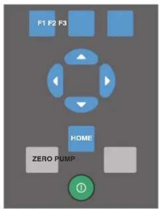
hbb005.eps
| Button | Description |
| 1 Push to turn on the Product. | |
| F1, F2, F3 | Softkeys to configure the Product and move through the Product menus. The button function changes in relation to the navigation menu. |
| ZERO Push to zero pressure measurements. | |
| PUMP Push to start the electric pump. | |
| , ▶, ▼, ▲ | Push to control mA source/sim and to set pump and % error limits. |
| HOME Push to go to the Product main screen. | |
Figure 1. Buttons
Display
The display can be made up of a maximum of three process measurement sections plus the menu bar which is always at the bottom of the display. The sections of the display are referred to by the Product and in this manual as UPPER, MIDDLE, LOWER, and menu bar. Push the softkeys that correspond to items shown on the menu bar to move through the Product menus. The arrow keys change values for some menu steps. See “Product Menus”.
The Display sections are shown in Figure 2.
![[P1] Psi 0.01 [P1] Psi 10.01 mA MEASURE -25.00% 0.000 mA MENU | LOWER | LIGHT ① ② ③ ④ ⑤ ⑥](/content/2026/05/897383/images/688d40b3ab095bc0db2f4025db34e65f45598a0f6cac87ed1e855f909f169b47.jpg)
hbb008.eps
| Item | Description |
| 1 | Menu Bar- Access the Product menus and parameters from the menu bar. See the “Product Menus” section. |
| 2 | Active Display- On the main menu, the middle of the menu bar shows the active display. In this image, the LOWER display is active. This section of the menu bar can also say UPPER and MIDDLE. This depends on which section is active. |
| 3 | UPPER display section |
| 4 | MIDDLE display section |
| 5 | LOWER display section |
| 6 | Pressure Units- Pressure units are shown in this section of the display. Select from 14 pressure units. |
| 7 | Span Indicator- Percentage of the 4 mA to 20 mA span when the mA or mA loop functions that are used show in this section of the display. |
| 8 | Primary Parameter- Shows the current measured parameter. |
Figure 2. Display
Calibrator Interface
The pressure controls are shown in Figure 3.
![FLUKE 300 V (FIRE) V (AIR) CHAMP [PI] PSS 30.00 PENI LOWER LIGHT AIR SUPPLY SOMAR OUTPUT 供电电源好 CLOSED PRESSURE STRAW ISOLATION VALVE SUSCVING CANCE OF DIFFERING FLOW SUPPLY METERING VALVE PRESSURE VACUUM VENT CACT PUMP CAUTION VEAT UNIC DRYING MARGIN SELECTION ZERO FLAM V mA AMERICAN OUT COM 24 V DC POWER 100kW 200kW 300kW 400kW 500kW 600kW 700kW 800kW 900kW](/content/2026/05/897383/images/d21154e25665a449c48122c1c3d3487a260641dd5e1a4f44fd81ea34d7c6f2e2.jpg)
hbb006.eps
| Item | Description |
| 1 | Supply metering valve. Use the supply metering valve to regulate the incoming air supply. See the “Typical Connections” section for more. |
| 2 | Isolation valve. This valve isolates the right-most port and pressure sensor from the Vent/Fine adjust, pump, and Supply Metering Valve. |
| 3 | Pump Pressure/Vacuum. In the + position, the pump operates from 0 psi to 300 psi. In the - position, the pump runs in vacuum mode, which is 0 psi to -12 psi. |
| 4 | Fine adjust/vent. Use the small silver knob of this valve to bleed off the pressure in a controlled manner. If left open, it will vent all pressure off safely. The outer-most knob (black) is a vernier control that varies the volume which finely reduces or increases the pressure. |
| 5 | Power Adapter input. |
| 6 | 24 V power for voltage transmitters. This jack only powered when in Voltage Measure mode. |
| 7 | Common Jack. |
| 8 | Input Jacks. Use the input jacks for volts and milliamp functions. See the “Measure and Source Current (4... 20 mA)” and “Measure Voltage” sections. Also used for switch test. |
| 9 | External pressure module connection. See the “External Modules” section. |
Figure 3. Controls
Typical Connections
Typical connections of the pressure controls, connection port, and electrical inputs are shown in Figures 4, 5, and 6.
![0 psi to 300 psi Air Supply Fully Closed PULSE 0.152 OUTPUT CLOSED OVERTIC BOLATION VALVE PRESSURE VACUUM CAUTION AUTO LINE OF VEC MOTOR SWITCH VENT FINE ADJUSTMENT PUMP CONTROL CONTROL MODE [PS] 300.00 MENU LOWER LIGHT FLI PS HODE 200Ω PUMP VMA SWITCH TEST COM 26 V DC RUNCE WTR RAGE SHEE SHEE SHEE SHEE SHEE SHEE SHEE SHEE SHEE SHEE SHEE SHEE SHEE SHEE SHEE SHEE SHEE SHEE SHEE SHEE SHEE SHEE SHEE](/content/2026/05/897383/images/fbf8e5cbb947c0abbefd3c7b09f4aadb55ce2f01245165b229fab1cd4ebbf5b4.jpg)
Figure 4. External Pressure Supply
hbb002.eps
![Closed Silver Vent Knob Fully Closed PUBO 300.00 [PI] PSL PDDI COLOR LIGHT F12 PD CLOSE ANALYZIC OPERATING PMS SHP ZERO PUMP COM 24 V DC Vina VOUT OUTPUT BALTIMES BALTIMES CLOSED PRESSURE VACUUM CAUTION VEGET OF OFFICE METER SWITCH EFFECT FUEL ADJUSTMENT PRESSURE VACUUM EFFECT OF OFFICE METER SWITCH](/content/2026/05/897383/images/2bbcfc49f1187ba84b2971374690f66e1801b9d46fcdac89eb5dfd593fea32a6.jpg)
Figure 5. Pressure Supply with Internal Pump
hbb003.eps
![-12 psi to 300 psi Pressure Source [PI] 300.00 AIR SUPPLY FLUTS OUTPUT CLOSED HENSOLATE OUTRUN PULSE VOLTAGE METERING VALVE PRESURE VACUUM PUMP CAUTION MAXIMUM INTEGRATED SWITCHER -12 psi to 300 psi Pressure Source [PI] 300.00 FLUTS HENSOLATE METERING VALVE PULSE VOLTAGE PULSE VOLTAGE MAXIMUM INTEGRATED SWITCHER -12 psi to 300 psi Pressure Source [PI] 300.00 FLUTS HENSOLATE METERING VALVE PULSE VOLTAGE PRESURE VACUUM PUMP CAUTION MAXIMUM INTEGRATED SWITCHER](/content/2026/05/897383/images/dfcdd4e6a5f2a02dcd823f966c0796f265cf588646ce393f49b3f60ddbf410ba.jpg)
Figure 6. Pressure Measurement
hbb004.eps
Power Options
The Product can be powered with the internal, high-capacity NiMH battery and/or the universal power supply (90 V ac to 250 V ac) that charges the battery pack. The universal power supply can power the Product at the same time it charges the battery pack. A fully-discharged battery can take a maximum of 14 hours to recharge. When the Product is first received, plug it into the universal power supply for that period to ensure the Product is fully charged.
Product Startup
When you turn on the Product, it goes through a short self-test. The display shows the current firmware version, auto-shutdown status, and the range of the internal pressure sensor. The Product also shows the warning “⚠️ FOR USE WITH DRY GAS ONLY”.
A minimum 5-minute warm-up is necessary to get the rated accuracy of the Product. If there are large changes in ambient temperature, a longer warm-up is necessary.
Pressure ranges must be zeroed each time the Product is started. See the “Zero Function” section for instructions to zero the pressure sensor displays.
Product Menus
The menu bar at the bottom of the display is controlled with the softkeys or arrow keys, this depends on which menu is in use. Use the menu bar to navigate the Product menus. The menus are explained in the subsequent sections. A menu map is shown in Figure 7.
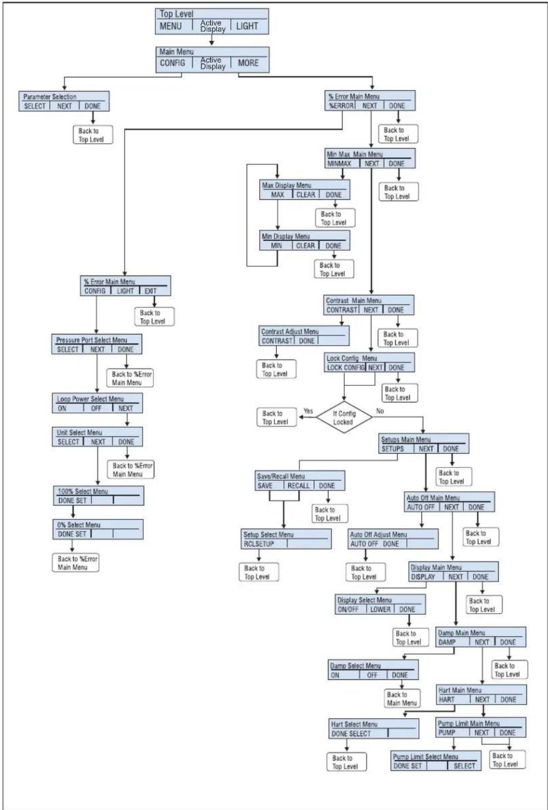
flowchart
graph TD
    A["Top Level"] --> B["MENU"]
    B --> C["MAIN Menu CONFIG"]
    C --> D["Active Display"]
    C --> E["MORE"]
    D --> F["Parameter Selection SELECT NEXT DONE"]
    F --> G["Back to Top Level"]
    E --> H["% Error Main Menu %ERROR NEXT DONE"]
    H --> I["Min Max Main Menu MINMAX NEXT DONE"]
    I --> J["Max Display Menu MAX CLEAR DONE"]
    J --> K["Back to Top Level"]
    J --> L["Min Display Menu MIN CLEAR DONE"]
    L --> M["Back to Top Level"]
    J --> N["Contrast Main Menu CONTRAST NEXT DONE"]
    N --> O["Contrast Adjust Menu CONTRAST NONE"]
    O --> P["Back to Top Level"]
    N --> Q["Lock Config Menu LOCK CONFIG NEXT DONE"]
    Q --> R{If Config Locked}
    R -->|Yes| S["Back to Top Level"]
    R -->|No| T["Setups Main Menu SETUPS NEXT DONE"]
    T --> U["Auto Off Main Menu AUTO OFF NEXT DONE"]
    U --> V["Back to Top Level"]
    T --> W["Display Main Menu DISPLAY NEXT DONE"]
    W --> X["Back to Top Level"]
    U --> Y["Auto Off Adjust Menu AUTO OFF DONE"]
    Y --> Z["Back to Top Level"]
    V --> AA["Display Select Menu ON/OFF LOWER DONE"]
    AA --> AB["Damp Main Menu DAMP NEXT DONE"]
    AB --> AC["Back to Top Level"]
    V --> AD["Hart Main Menu HART NEXT DONE"]
    AD --> AE["Pump Limit Main Menu PUMP NEXT DONE"]
    AE --> AF["Pump Limit Select Menu DONE SET SELECT"]
    AF --> AG["Back to Top Level"]
    F --> AH["% Error Main Menu CONFIG LIGHT EXIT"]
    AH --> AI["Back to Top Level"]
    AI --> AJ["Pressure Port Select Menu SELECT NEXT DONE"]
    AJ --> AK["Back to %Error Main Menu"]
    AK --> AL["Loop Power Select Menu ON OFF NEXT"]
    AL --> AM["Unit Select Menu SELECT NEXT DONE"]
    AM --> AN["Back to %Error Main Menu"]
    AN --> AO["100% Select Menu DONE SET"]
    AO --> AP["0% Select Menu DONE SET"]
    AP --> AQ["Back to %Error Main Menu"]
Figure 7. Menu Map
hbb001.eps
Top-Level Menu
The top-level menu is shown in Figure 8. It has three levels.

Figure 8. Top-Level Menu
hbb009.eps
- MENU- Push the MENU softkey to get to the main menu. See the "Main Menu" section.
- [Active Display]- The active display is shown in the middle field on the top-level and main menu. In Figure 8 the active display is the LOWER display. This menu item lets you assign the ZERO key to one of the three display sections. Push the softkey that corresponds to the display named on the menu bar to change the active display. If the chosen display is a pressure range, then the ZERO key becomes active.
- LIGHT- The Product has a backlight for low-light situations. To turn on or turn off the backlight, push the LIGHT softkey on the main menu. The backlight cannot be controlled by the serial interface.
Main Menu
To go to the main menu, push the MENU softkey from the top-level menu. From the main menu, the submenus can be accessed. The main menus are:
- Config- Display Configuration menu
• % Error Main Menu - MinMax Menu
- Contrast Main Menu
- Lock Config Menu
- Setups Main Menu
- Save/Recall Menu
• Auto Off Main Menu - Setups Main Menu
- Display Main Menu
- Damp Main Menu
• HART Main Menu - Pump Limit Main Menu
Some of these menus are broken up into more submenus.
The main menu is shown in Figure 7 and has three levels.

Figure 9. Main Menu
hbb010.eps
- CONFIG (Configuration) - Push F1 to access the config menu. Push F1 again to go to the Display Configuration menu. This will let you change the parameters for each display section. See the Parameter Selection portion of the Figure 7.
• [Active Display] - See the "Top-Level Menu" section. - MORE-Push F3 to access the % Error Main Menu.
Display Configuration Menu
Use the display configuration menu to set the parameters of the active display. Push the SELECT softkey to move through this menu. See Figure 13.

Figure 10. Display Configuration Menu
hbb011.eps
The first parameter is Mode. Since voltage, current, and switch test modes all use the same jacks, two of these functions cannot be used at the same time. What can be selected depends on what is already selected in another display.
Push the NEXT softkey to change the second parameter. Pressure can be read in 14 different engineering units. Only Pressure mode has a second parameter.
These modes are available with a single display:
• P[1] = Pressure internal sensor
- [EXT] = Pressure with external pressure module
- P[1] ST = Switch Test with internal sensor
- [EXT] ST = Switch Test with external pressure module
Note
mA functions are only available on the lower section of the display.
• mA Measure = Milliamps measure.
- mA Source = Milliamps source.
• SIM-2W = Milliamps simulate using an external supply from the UUT.
• VOLTS = Voltage Measure.
- mA MEAS/24v
Table 2 shows which functions are available concurrently.
An X in a column indicates that the mode in the active display is not available for selection if the mode in that row is in use in a different display.
Use the MORE option on the main menu to access other menu functions.
Table 2. Mode Concurrency
| Active Display | ||||||||
| P[1] | [EXT] | P[1]ST | [EXT]ST | mA | mAMEAS/24V | Volts | ||
| Other Displays | P[1] | x | x | x | x | x | x | |
| [EXT] | x | x | x | x | x | x | ||
| P[1]ST | x | x | ||||||
| [EXT]ST | x | x | ||||||
| mA | x | x | x | |||||
| mAMEAS/24V | x | x | x | |||||
| Volts | x | x | x | |||||
×
Zero Function
When is pushed, the Product zeros its active display if a pressure mode is selected, and the pressure is within the zero limit. The zero limits are within 10 % of the full-scale range of the selected sensor. If the display shows “OL,” the zero function will not operate. is only used for pressure.
Internal Sensor and Pressure Module (non-absolute)
When a sensor or pressure module is selected on the active display and ZERO is pushed, the Product subtracts the current reading from the output. The zero limits are within 10 % of the full-scale range of the selected sensor. If the display shows “OL,” the zero function will not operate.
Absolute Pressure
When an absolute pressure range is selected on the active display and ZERO is pushed, the Product prompts you to enter the barometric reference pressure. Record the barometric reference pressure with the arrow buttons. While you do this procedure, make sure the sensor port is open (vented) to the atmosphere. See Figure 11.
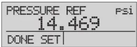
Figure 11. Absolute Pressure
hbb012.eps
Other Menu Controlled Functions
There are many submenus below the main menu. These can be accessed through the MORE option of the main menu. A submenu contains three options. The first option is unique to the function. The second and third options are always the same. The NEXT option leads to the subsequent menu. The DONE option goes home. For the last menu, the NEXT option goes home. See Figure 7 for the menu structure.
In this manual, if a submenu has subsequent menus below it, it is referred to as {function} main menu. As an example, the display contrast submenu will be called the Contrast main menu.
Contrast Main Menu
To set the contrast, go through the menu list until CONTRAST is shown. Push the CONTRAST softkey to access the Contrast Adjustment menu.
Push the up arrow or down arrow softkey to change the display to the necessary contrast level. When completed, push the CONTRAST DONE softkey to go home. See Figure 12.
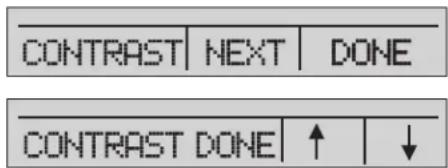
Figure 12. Contrast Menu
hbb013.eps
Lock or Unlock the Display Configuration
To lock or unlock the display configuration settings, go through the menu list until LOCK CFG is shown. Push the LOCK CFG or UNLOCK CFG softkeys from the Configuration Lock menu. See Figure 13.

Figure 13. Display Configuration Menu
hbb014.eps
When the LOCK CFG option is used, the menu goes home and the CONFIG option on the main menu shows that it is locked. All menus are now locked except for Min Max, Contrast Adjustment, and Configuration Lock. When the UNLOCK CFG option is used, the configuration is unlocked and the menu goes to the next sub menu.
Save and Recall Menu Setups
The current Product setup is saved for recall at the next power up. Five different setups can be saved for later use. To access these setups, go through the menu list until SETUPS is shown. Push the SETUPS softkey from the Setups Main menu. Push the RECALL softkey to recall a setup or the SAVE softkey to save a setup. Push the DONE softkey to do nothing and go to the home menu.
If SAVE or RECALL is selected, push the arrow keys to select the setup location. Then push the SAVE softkey to store the current setup into the selected location. You can also push the RECALL softkey to recall the setup stored in the selected location. The display menu will go to home. See Figure 14.
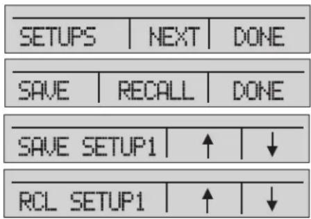
Figure 14. Setups Menu
hbb015.eps
Automatic Shutdown
The Product can be set to turn off after a preprogrammed time interval, 0 minutes to 30 minutes. To set the automatic shutdown, go through the menu list until AUTO OFF is shown. Select the AUTO OFF option on the Auto Shutdown main menu
Push the arrow softkeys to choose the number of minutes the Product functions. Or push the down arrow softkey until OFF is shown to disable the automatic shutdown. When you have made the selection, push the AUTO OFF DONE softkey to set the selection. The Product menu will go to the home menu. The auto shutdown timer is reset when a button is pushed. See Figure 15.
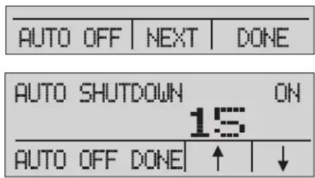
Figure 15. Auto Shutdown Menu
hbb016.eps
Activate and Deactivate a Display
Use the DISPLAY menu to select which display to use. The ON/OFF option turns the selected display on or off. The selected display and current on/off state are shown in the lower display. See Figure 16.
To choose which displays are active:
- Go through the menu list until DISPLAY is shown.
- Push the DISPLAY softkey to access the Display Activation menu.
- Push the UPPER, MIDDLE, or LOWER softkey to make your selection.
- Push the ON/OFF softkey to the change the display state.
- Push the DONE softkey to save the changes and go to the home screen.
When a display is deactivated, its configuration is saved. When the display is activated, its configuration is verified against the configurations of the other currently-active displays. If the configurations are in conflict, the recalled-display configuration is changed to prevent the conflict. If all three displays are deactivated, the lower display will turn on automatically.
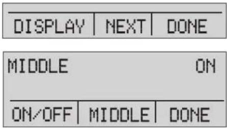
Figure 16. Active Display Menu
hbb017.eps
Damping
Damping can be turned ON or OFF with the DAMP menu selection. Go through the menu list until DAMP is shown. Select ON or OFF. When damping is ON, the Product shows a running average indication of ten measurements. The Product makes approximately three readings per second.
HART Resistor
An internal 250 Ω HART resistor can be enabled when the Product is used in the mA Measure-24V mode. This lets a HART communicator be connected across the mA terminals and makes it unnecessary to add an external resistor.
Note
When the HART resistor is on, the maximum load-driving capacity is 750 .
Go through the menu list until HART is shown. Use the arrow softkeys to select ON or OFF.
Pump Limits
To prevent overpressure of sensitive devices the maximum pressure (pump limit) can be set. Go through the menu list until PUMP is shown. When in this mode, use SELECT and the arrow buttons to change the pump limit. Push the DONE SET softkey to save the selection and go to the main menu. This limit can be set to 10 % above full scale.
Initial Setup and Basic Pressure Generation
The Product has a special low-volume calibration hose for faster pressure generation and quick pressure stabilization. "Quick-fit" hose connectors and different adapters are included. It is recommended that this hose is used to get the best results. After the fittings are installed and the Product is connected to the UUT (unit under test), the Product is ready for use.
To configure the Product for the appropriate application:
- Set the pressure/vacuum selection knob to the necessary function (+ for pressure and - for vacuum).
- Close the vent knob.
- Close the supply metering valve.
- Push and hold and see the pressure rise (or vacuum generation) until you reach the necessary pressure.
- Release PUMP when the necessary pressure is reached.
Note
The motor speed starts slow while the pressure is low <15 psi (1 bar) for better control at low pressures.
- The fine pressure adjustment lets you set the correct pressure.
- To decrease or bleed off all pressure, slowly turn the vent knob counter clockwise to the open position. When the valve is slowly opened, there is a slow decrease of pressure. Open the valve more to vent the pressure.
Pressure Measurement
To measure pressure:
- Connect the Product with the correct adapter.
- Select the pressure parameter for the display used.
- The Product has an internal sensor and optional external sensors are available. Select a sensor that is correct for the pressure range and accuracy.
⚠ Warning
To prevent injury, only assemble and operate high-pressure systems if you know the correct safety procedures. High-pressure liquids and gases are hazardous and the energy from them can be released without warning.
For a better understanding with respect to overpressure and burst pressure, follow the specifications and these operation instructions. See the "Specifications" section. The Product display will show "OL" when an inappropriate pressure is applied. When "OL" is shown on a pressure display, immediately decrease the pressure to prevent damage or possible physical injury. "OL" is shown if the pressure exceeds the nominal range by 110 %. Push ZERO to zero the pressure sensor after it is vented to atmospheric pressure.
Media Compatibility
The Product is only to be used with clean, dry gases.
External Modules
The Product has a digital interface to support the Fluke 700P series of pressure modules. These modules are available for different ranges that include gauge, vacuum, differential, and absolute pressure. The modules work in conjunction with the Product. Connect them to the interface and select [EXT] (external sensor). Since the interface between the Product and the module is digital, the accuracy and display resolution depends on the module. See Figure 17.
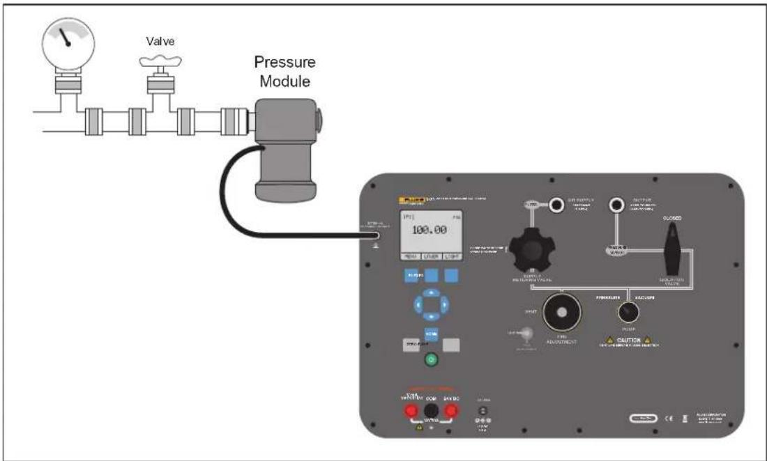
Figure 17. Pressure Module
hbb007.eps
Measure and Source Current (4... 20 mA)
To measure and source current:
- To measure current, use the input terminals on the front of the Product. Select the mA function on the lower display. Current is measured in mA and a percentage of the measuring range. The measuring range on the Product is set to 0 % at 4 mA and 100 % at 20 mA. See Figure 18 for connections.
Example:
If the current measured is shown as 75 %, then the value is 16 mA.
Note
The display shows "OL" when the measured current exceeds the nominal range of current measurement (24 mA).
- The same connections are used for the current source. Select mA-Source or mA Sim-2W from the configuration display.
- This selection can only be made in the lower display. Also, in source mode, the Product generates 0... 24 mA that uses its own internal 24 V supply, whereas in simulation mode the Product acts as a 2-wire transmitter and an external 24 V supply is necessary.
- Push the arrow key to start the output mode and then use the arrow keys to adjust the mA output. The function keys can also be used to control the output in 25 % steps (4, 8, 12, 16, 20 mA) or 0 % (4 mA) and 100 % (20 mA). See Figure 18.
- While in the mA output mode, if the loop is broken or the resistance burden is exceeded, the Product will flash "OL".
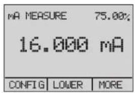
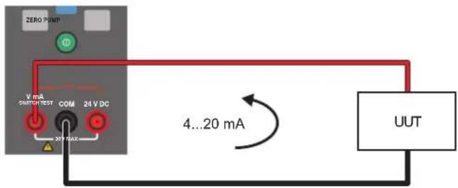
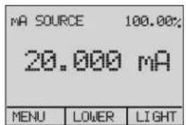
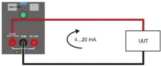
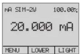
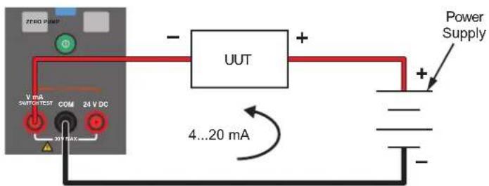
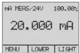
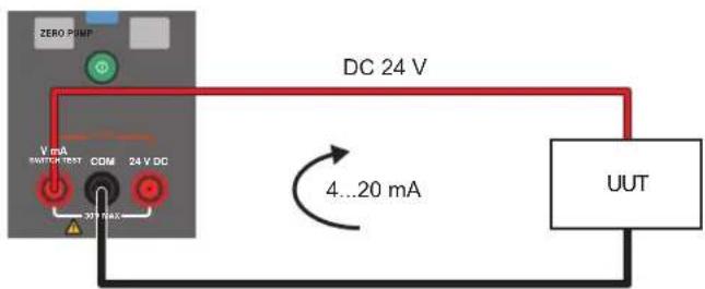
Figure 18. Measure and Sourcing Current
hbb018.eps
Measure Voltage
To measure voltage, use the connections on the front of the Product. Select the VOLTS function on one of the displays. The Product can measure to a maximum of 30 V dc. See Figure 19.
Note
The display shows "OL" when the measured voltage is larger than the nominal range of voltage measurement (30 V).
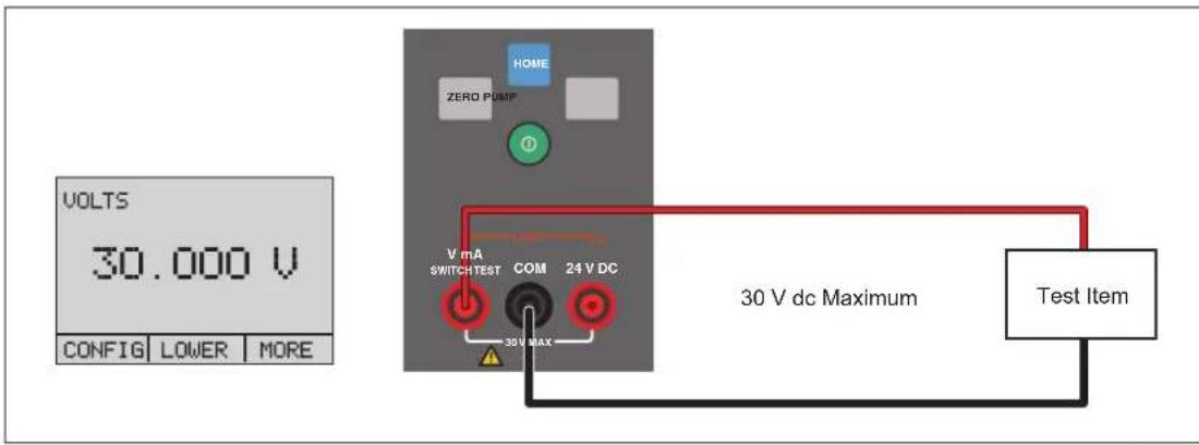
Figure 19. Measure Voltage
hbb019.eps
Pressure Switch Test
To do a pressure switch test:
- Set the upper display to [P1] ST, all other displays are switched off.
Note
The pressure switch test can be done with these functions: [P1] ST or EXT ST.
- Connect the Product to the pressure switch with the switch terminals. The polarity of the terminals is not important. See Figure 20.
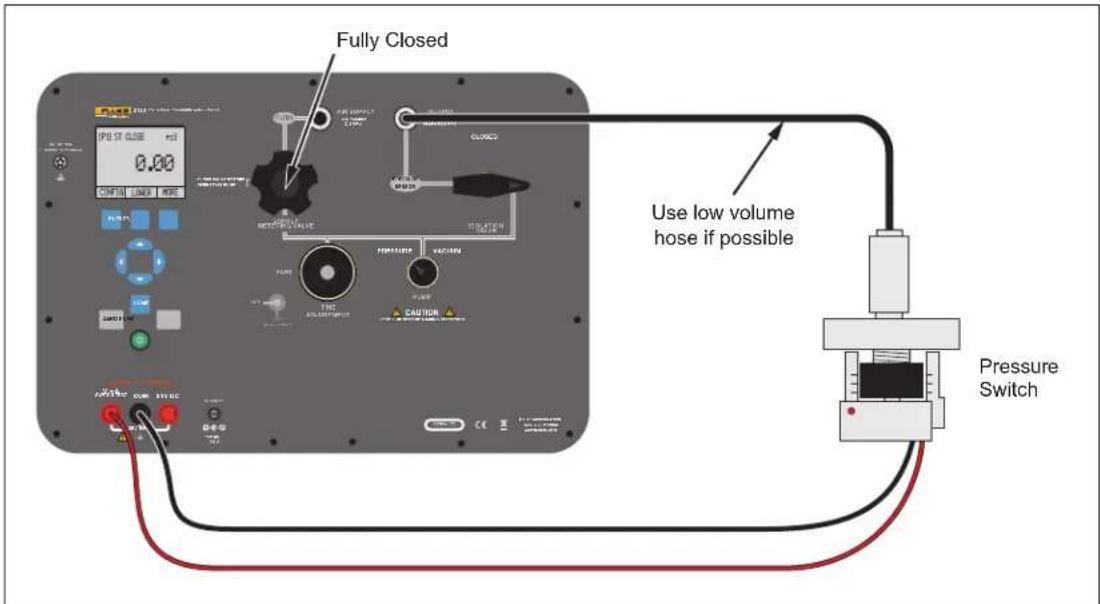
Figure 20. Switch Test Connections
hbb020.eps
- Connect the Output of the Product to the pressure switch.
- Open the vent button on the pump and zero the Product.
- Close the vent after you reset the Product.
The top of the display shows "CLOSE". See Figure 22.
![[P1] ST CLOSE Psi 0.00 CONFIG LOWER MORE](/content/2026/05/897383/images/f35dc21afd56969e52dc94fd262ab40e6290353b698eb6f881016ebb92a6bedb.jpg)
Figure 21. Switch Test Screen
hbb021.eps
- Apply pressure with the pump slowly until the switch opens.
Note
In the switch test mode, the display-update rate is increased to help capture changes to pressure inputs. Even with this enhanced sample rate, the UUT should be charged slowly with pressure to ensure accurate readings.
- After the switch is open, "OPEN" will be shown. Bleed the pump slowly until the pressure switch closes. See Figure 22.
![[P1] ST OPEN Psi 30.00 CONFIG LOWER MORE](/content/2026/05/897383/images/a494b06fed67a2d4da6a488c1ecbe0bf1551d07a161fc7ce6da7834c9c399f59.jpg)
Figure 22. Switch Test Screen (Open)
hbb022.eps
- The top display now shows "SW OPENED AT" and gives you the pressure at which the switch opened. See Figure 23.
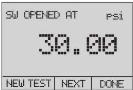
Figure 23. Opened Switch Reading
hbb023.eps
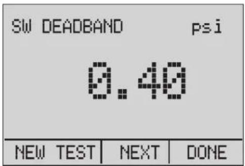
- Select the "NEXT" option to show the pressure at which the switch closed and the deadband. See Figure 24.
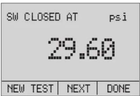
hbb024.eps
Figure 24. Switch Test and Deadband Results
- Select the "NEW TEST" option to clear the data and do another test.
- Select the "DONE" option to complete the test and go to the standard pressure setting.
Example:
[P1] ST will return to [P1].
This example uses a normally closed switch. The basic procedure is effectively the same for a normally open switch. The display reads "OPEN" instead of "CLOSE".
Calibrate Transmitters
Use the mA Measurement Function
The mA function lets you read the 4... 20 mA output from the UUT. This can be done in two ways:
- Passively – the UUT generates 4... 20 mA directly. This can be read on the Product.
- Actively – the Product supplies a loop power of 24 V dc to the UUT to power the device while it reads the 4... 20 mA signal. See Figure 25.
PassiveActive
![[P1] Psi 30.00 mA MEASURE 100.00% 20.000 mA CONFIG LOWER MORE](/content/2026/05/897383/images/95eb52800ae764e9f5508c6f59d229eb62beafb126684da0b3834b037947498c.jpg)
![[P1] Psi 30.00 mA MEAS/24V 100.00% 20.000 mA CONFIG LOWER MORE](/content/2026/05/897383/images/3a5616634bc30784aaee65cc31d5421d3e18fa764c2dd12d267784b69a2c47fd.jpg)
hbb025.eps
Figure 25. Passive and Active Screens
Calibrate a Pressure-to-Current Transmitter
To calibrate a pressure-to-current transmitter (P/I):
- Connect the Product pump to the transmitter.
- Apply pressure from the pump.
- Measure the current output of the transmitter.
- Make sure that the read value is correct. If it is not correct, the transmitter must be adjusted. See Figure 26.

Figure 26. Calibrate a Pressure-to-Current Transmitter
hbb026.eps
Calibrate a Pressure-to-Voltage Transmitter
To calibrate a pressure-to-voltage transmitter (P/V):
- Connect the Product pump to the transmitter.
- Apply pressure from the pump.
- Connect the 24 V to the transmitter.
- Measure the voltage output of the transmitter.
- Make sure that the read value is correct. If it is not correct, the transmitter must be adjusted. See Figure 27 for connections.
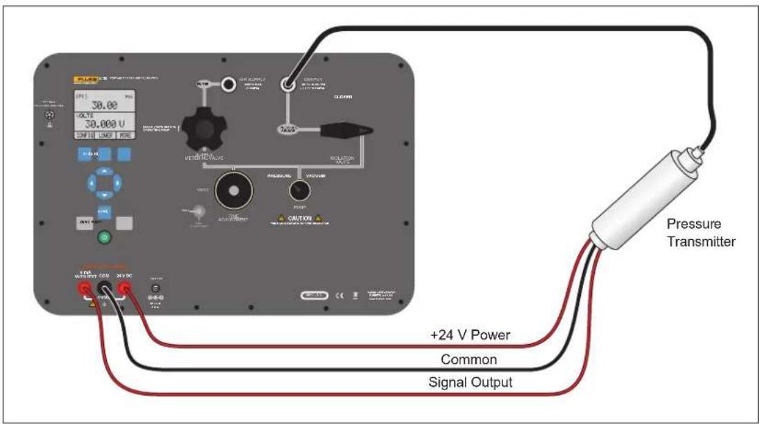
Figure 27. Calibrate a Pressure-to-Voltage Transmitter
hbb035.eps
%-Error Function
The Product has a special function which can calculate the error in the pressure value from the mA value as a percentage of the 4 ... 20 mA loop span. The %-Error mode uses all three screens and has a special menu structure. It shows pressure, mA and %-Error simultaneously. See Figure 28.
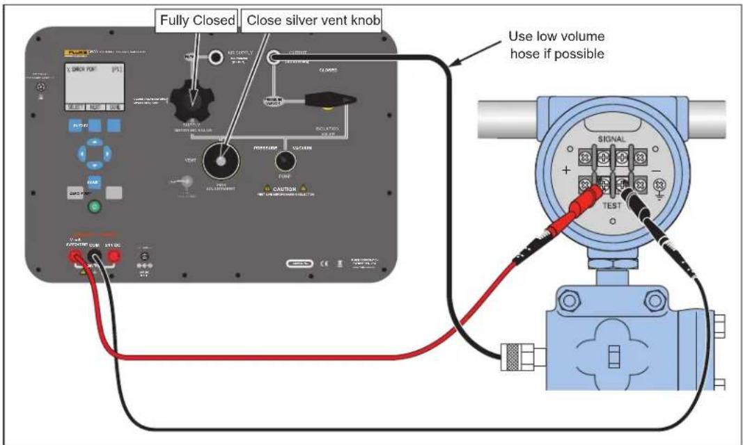
Figure 28. Connections with a Pressure Transmitter with % Error Function
hbb027.eps
Example:
If a pressure transmitter under test has a full-scale range of 2 bar and gives a 4 ... 20 mA output signal, you can program in a 0 ... 2 bar pressure span into the Product. The Product will then calculate and show the deviation or %-Error value from the 4 ... 20 mA output. This makes manual calculations unnecessary.
To use the "%-ERROR" function:
-
Once the Product is turned on, push F3 to start the "MORE" menu option. Then Push F1 to start the "%-ERROR" option.
-
Push F1 to select the "CONFIG" option.
-
The first option is the port setting. Use the "SELECT" option to scroll through the choice of ports (pressure connections). When this is done, select the "NEXT" option. See Figure 29.
![% ERROR PORT [P1] SELECT NEXT DONE](/content/2026/05/897383/images/4abf1e7c74fdca26650aad3aee0946529063cdf8d38468fcf6b9c201ee58c7bd.jpg)
Figure 29. Port Setting Screen
hbb028.eps
- "LOOP POWER" can be toggled on or off. Select "NEXT" when done. See Figure 30.
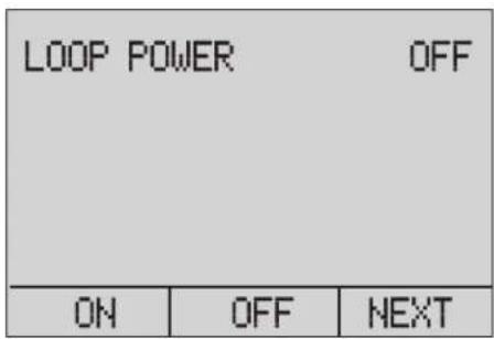
Figure 30. Loop Power Screen
hbb029.eps
- Use "SELECT" to scroll through the "UNIT" options, and select "NEXT" to move on. See Figure 31.
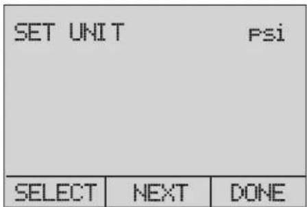
Figure 31. Set Unit Screen
hbb030.eps
- Use the arrow keys to set the upper limit of the measurement range. Select DONE SET when finished. See Figure 32.
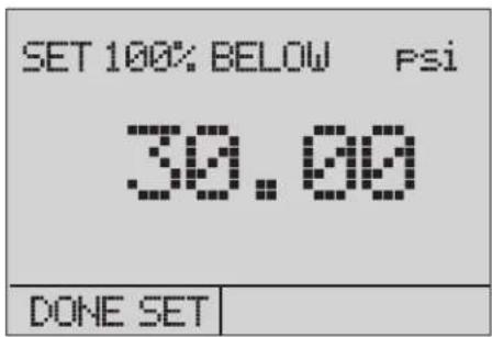
Figure 32. Setting the Upper Limit
hbb031.eps
- Use the arrow keys to set lower limit of the measurement range, and select DONE SET when finished. The "%-ERROR" mode will be ready to use. See Figure 33.
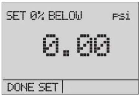
Figure 33. % ERROR Screen
hbb032.eps
The lower and upper limit of the measuring range is saved in non-volatile memory until they are changed by the user for the internal sensors and the external pressure modules. See Figure 34.
![[P1] Psi 0.00 mA measure -25.00% 0.000 mA % Error -25.00% CONFIG | LIGHT | EXIT](/content/2026/05/897383/images/4b1cff01050c8bbc2cb3a5450e17184227563e4ac8a002ee3bad7cdcd038a8af.jpg)
Figure 34. Saved Upper and Lower Limits
hbb033.eps
Storage Capability
The Product has a min/max feature to capture the minimum and maximum values of a shown parameter.
The min/max function can be accessed by going through the menu options until the MINMAX menu choice is shown. Push the MINMAX softkey to see the min/max values that are stored in the min/max registers. These readings are live so that the new min/max values are recorded while in this mode.
To reset the min/max registers, push the CLEAR softkey. These registers are also cleared at power-up or when the configuration is changed.
Remote Operation
The Product can be remotely controlled with a PC terminal, or by a computer program that runs the Product in an automated system. An RS-232 serial port connection is used for remote operation.
Note
To use the remote control option, a custom RS-232 cable must be purchased. See the "How to Contact Fluke Calibration" section.
With this connection, you can write programs on the PC. Use Windows languages like Visual Basic to operate the Product, or use a Windows terminal like Hyper Terminal, for single commands. A typical RS-232 remote configuration is shown in Figure 35.
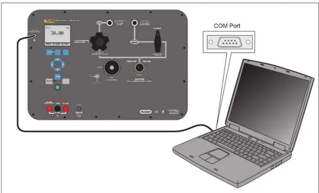
Figure 35. Remote Operation
hbb034.eps
Set Up the RS-232 Port for Remote Control
Note
The RS-232 connection cable must be less than 15 m unless the load capacitance measured at connection points is less than 2500 pF.
Serial parameter values:
- 9600 baud
- 8 data bits
- 1 stop bit
- no parity
- Xon/Xoff
- EOL (End of Line) character or CR (Carriage Return) or both
An RS-232 cable is used for RS-232 communications from the Product to a computer. If the computer only has USB ports, a USB to RS-232 converter will be necessary. To connect the Product to a computer, attach the LEMO connector end of the cable to the pressure module port on the right side of the Product. Then connect the DB-9 connector to the RS-232 port on the computer. The Product must be off before you make the connection.
To set up remote operation of the Product with Windows Hyper Terminal, connect the Product to a COM port on the PC. See Figure 35.
Do the subsequent procedure:
- Start Hyper Terminal (located on your computer in Accessories/Communications of the Windows Start menu).
- Select New Connection.
- For Name enter "Fluke 3130".
- Select the serial port that the Product is connected to.
- Enter the above information for port settings.
-
Select ASCII setup from File/Properties/Settings and mark these choices:
-
Echo typed characters locally
-
Wrap lines that exceed terminal width
-
Select Ok.
-
To see if the port functions, enter *IDN?. This command shows information on the Product.
Change from Remote to Local Operation
The Product uses three modes of operation:
- Local
- Remote
- Remote with Lockout
Local mode is the default mode. Commands can be entered with the buttons on the Product or with a computer. In Remote mode, the buttons are disabled and commands can only be entered with a computer. Select [GO TO LOCAL] from the menu on the Product display to restore button operation. In Remote with Lockout mode, the buttons cannot be used.
To switch modes:
- To start Remote mode, enter the serial command "REMOTE" at the computer terminal.
- To start Remote with Lockout mode, enter "REMOTE LOCKOUT" in either order.
- To go back to Local Operation mode, enter "LOCAL" at the terminal. This command also turns off LOCKOUT if it is on. For more information on commands, see the "Remote Commands" section.
Command Use
The Product can be controlled by commands and queries. All commands can be entered with upper or lower case. See the Remote Commands section for all available commands.
The commands are divided into these categories:
Calibrator Commands
Only the Product uses these commands.
For example:
VAL?
This command requests the values shown on the Product display.
Common Commands
Standard commands used by most devices. These commands always start with an “*”.
For example:
*IDN?
This command tells the Product to show its identification.
Query Commands
Commands that request information and always end with a “?”.
For example:
FUNC?
This command shows the current modes of the Product displays.
Compound Commands
Commands that have more than one command on one line.
For example:
PRES_UNIT LOWER, PSI; PRES_UNIT?
This command sets the pressure unit to PSI on the lower display and queries the Product to verify. In this case, it will show the pressure units of all three displays:
BAR,BAR,PSI
Character Processing
The data entered into the Product is processed as follows:
- ASCII characters are discarded if their decimal equivalent is less than 32 (space), except 10 (LF) and 13 (CR):
• Data is taken as 7-bit ASCII. - The most significant data bit is ignored.
• Upper or lower case is acceptable.
Response Data Types
The data shown by the Product can be divided into these types:
Integer
For most computers and controllers they are decimal numbers ranging from -32768 to 32768.
For example:
FAULT?
Could show 110
Refer to the Error Codes table (Table 8) for more information on error codes.
Floating
Floating numbers can have a maximum of 15 significant figures and exponents.
For example:
VAL?
Shows 5.830000E01, PSI, 0.000000E00, PSI, 0.000000E+00, A
Character Response Data (CRD)
Data shown as keywords.
For example:
PRES_UNIT?
Shows BAR, BAR, PSI
Indefinite ASCII (IAD)
Any ASCII characters followed by a terminator. For example:
*IDN?
Shows Fluke, 3130, 1234567, 1.00 (1234567 is the serial number)
Calibrator Status
Error Queue
If an error occurs from invalid input or buffer overflow, its error code is sent to the error queue. The error code can be read from the queue with the command FAULT?. The error queue holds 15 error codes. When it is empty, FAULT? shows 0. The error queue is cleared when power is reset or when the clear command *CLS is entered.
Input Buffer
The calibrator stores all received data in the input buffer. The buffer holds 250 characters and they are processed on a first in, first out basis.
Remote Commands and Error Codes
This section shows and describes all of the remote commands that are accepted by the Product.
Table 3. Common Commands
| Command Description | |
| *CLS (Clear status.) Clears the error queue. | |
| *IDN? Identification query. Shows the manufacturer, | model number, and firmware revision level of the Product. |
| *RST Resets the Product to the power up state. |
Table 4. Product Commands
| Command | Description |
| DAMP Turns on or off Damp | |
| DAMP? Show if DAMP is on/off | |
| DISPLAY Turns on or off the displays specified in the command | |
| DISPLAY? Shows which displays are on/off | |
| ERROR_LOOP Turns on or off loop power in percent error mode | |
| ERROR_LOOP? Shows the current state of loop power in error mode | |
| ERROR_MODE Turns on or off percent error mode | |
| ERROR_MODE? Shows if percent error mode is on or off | |
| ERROR_PORT Set the pressure port for percent error mode | |
| ERROR_PORT? Shows the pressure port for percent error mode | |
| FAULT? Shows the most recent error code | |
| FUNC Sets the display mode as specified in the command | |
| FUNC? Shows the current mode of the upper, middle, and lower display | |
| HART_ON Turns on the HART resistor | |
| HART_OFF Turns off the HART resistor | |
| HART? | Shows the current state of the HART resistor. |
| HI_ERR | Sets the 100 % of span limit for percent error mode |
| HI_ERR? Shows the 100 % of span limit for percent error mode | |
| IO_STATE | Set the Product mA state |
| IO_STATE? Shows the Product mA state | |
| LOCAL Shows user to manual operation of the Product | |
| LOCKOUT | Locks out the keypad of the Product in remote operation |
| LO_ERR | Sets the 0 % of span limit for percent error mode |
| LO_ERR | Shows the 0 % of span limit for percent error mode |
| MOTOR_ON | Turns on the motor |
| MOTOR_OFF | Turns off the motor |
| MOTOR? | Shows the current state of the HART resistor |
| OUT | Set the Product to output the requested current |
| OUT? | Shows the value of the current being simulated |
| PRES_UNIT Set the pressure unit for the indicated display | |
| PRES_UNIT? Shows the pressure from the indicated display | |
| PUMP_LIMIT Sets the approximate value at which the pump will turn off | |
| PUMP_LIMIT? Shows the approximate value at which the pump will turn off | |
| REMOTE Puts the Product in remote mode | |
| SIM Set the Product to simulate the requested current | |
| SIM? Shows the value of the current being simulated | |
| ST_CLOSE? Shows pressure value at which the switch closed | |
| ST_DEAD? Shows pressure value of the deadband of the switch | |
| ST_OPEN? Shows pressure value at which the switch opened | |
| ST_START Starts a switch test | |
| VAL? Shows the measured values | |
| ZERO_MEAS Zeros the pressure module | |
| ZERO_MEAS? | Shows the zero offset of the pressure module |
Table 5. Parameter Units
| Units | Meaning |
| DCI | Current function |
| DCV | Voltage measure function |
| EXT | External pressure measurement function |
| LOWER | Designates Lower display |
| MA | Milliamps of current |
| MEASURE | Measure state |
| MEAS_LOOP | Measure with loop power state |
| MIDDLE | Designates Middle display |
| PCT_ERR | Percent Error |
| PERCENT | Percent |
| P1 | P1 pressure measurement function |
| ST_P1 | Switch test mode with P1 |
| ST_EXT | Switch test mode with external module |
| SOURCE | Source state |
| SIM | Simulate state |
| UPPER | Designates Upper display |
| V | Voltage |
Table 6. Error Codes
| Error Number | Error Description |
| 100 | A non-numeric entry was received where it should be a numeric entry |
| 101 | Too many digits entered |
| 102 | Invalid units or parameter value received |
| 103 | Entry is above the upper limit of the allowable range |
| 104 | Entry is below the lower limit of the allowable range |
| 105 | A required command parameter was missing |
| 106 | An invalid command parameter was received |
| 107 | Pressure not selected |
| 108 | Invalid sensor type |
| 109 | Pressure module not connected |
| 110 | An unknown command was received |
| 111 | Bad Parameter received |
| 112 | The serial input buffer overflowed |
| 113 | Too many entries in the command line |
| 114 | The serial output buffer overflowed |
Enter Commands
Commands for the Product can be entered in upper or lower case. There is a minimum of one space necessary between the command and parameter. All other spaces are optional. Most of the commands for the Product are sequential. Any overlapped commands will be shown as such. This section describes each of the commands and their general use, which will include any parameters that can be entered with the command as well as what the output of the command is.
Common Commands
*CLS
Clears the error queue. Also ends all pending operations. When you write programs, use this command before each procedure to prevent buffer overflow.
*IDN?
Shows the manufacturer, model number, and firmware revision of the Product.
For example:
*IDN?
Shows Fluke, 3130 0, 1.00
Calibrator Commands
DAMP
Turns on or off the dampening function.
For example:
If you send DAMP ON, this will turn the dampening function on.
DAMP?
Shows the current state of the dampening function.
For example:
If you send DAMP?, this will show ON if the dampening function is on.
DISPLAY
Turns on or off the indicated display.
For example:
If you send DISPLAY LOWER, ON, this will turn on the lower display.
DISPLAY?
Shows the current state of the each of the displays.
For example:
If you send DISPLAY?, it will show ON, ON, ON if the all the displays are on.
FAULT?
Shows the error code number of an error that has occurred. The command can be entered if the previous command did not do what it was meant to do.
For example, if a value for current output is entered that is larger than the supported range (0-24 mA), FAULT? shows:
103 which is the code number for an entry over range.
Refer to Table 6 for more information about error code numbers.
ERROR\_LOOP
Turns on or off loop power in percent error mode.
For example:
To set loop power on, send ERROR_LOOP ON.
ERROR\_LOOP?
Shows the current state of loop power in percent error mode.
For example:
If you send ERROR_LOOP?, it will show ON if loop power is on in error mode.
ERROR\_MODE
Turns on or off percent error mode.
For example:
To turn on percent error mode, send ERROR_MODE ON.
ERROR\_MODE?
Shows the current state of percent error mode.
For example:
If you send ERROR_MODE?, it will show ON if the Product is in percent error mode.
ERROR\_PORT
Sets the pressure port for percent error.
For example:
To set the pressure port for percent error to [P1] send ERROR_PORT P1.
ERROR\_PORT?
Shows the current pressure port for percent error mode.
For example:
If you send ERROR_PORT?, it will show P1 if the pressure port in percent error is [P1].
FUNC
Sets the display indicated in argument 1 to the function indicated in argument 2.
For example:
To set the lower display to pressure mode, send FUNC LOWER,[P1].
FUNC?
Shows the current mode of all displays. For example if the Product is set to [P2] ST on the upper display, [P1] on the middle, and [P1] on the lower, FUNC? shows:
ST_P2,P1,[P1]
HART\_ON
Turns on the Hart resistor.
HART\_OFF
Turns off the Hart resistor.
HART?
Shows the state of the Hart resistor.
For example:
If the Hart resistor was on, HART? shows ON.
HI\_ERR
Sets the 100 % point for the percent error mode calculation in the current engineering units.
For example:
To set the 100 % point to 100 psi, send HI_ERR 100.
HI\_ERR?
Shows the 100 % point for the percent error mode calculation.
For example:
If the 100 % point is set to 100 psi, HI_ERR? shows 1.000000E+02, PSI.
IO\_STATE
Sets the input/output/simulate state of the mA function of the Product. This does not put the Product into mA if it is not in it already.
For example:
If the Product is in mA simulate modem sending IO_STATE MEASURE would put it into measure mode.
IO\_STATE?
Shows the input/output/simulate state of the mA function of the Product.
For example:
If the Product was in mA simulate mode, IO_STATE? shows SIM.
LOCAL
Returns the Product to local operation if it was in remote mode. The command also clears LOCKOUT if the Product was in lockout mode.
LOCKOUT
Sending this command sets the lockout state, when the unit is in REMOTE or goes to remote, it stops use of the keypad completely. The lockout state can only be cleared by sending the LOCAL command.
LO\_ERR
Sets the 0 % point for the percent error mode calculation in the current engineering units.
For example:
To set the 0 % point to 20 psi, send LO_ERR 20.
LO\_ERR?
Shows the 0 % point for the percent error mode calculation.
For example:
If the 0 % point is set to 20 psi, LO_ERR? shows 2.000000E+01, PSI.
MOTOR\_ON
Turns on the motor.
MOTOR\_OFF
Turns off the motor.
MOTOR?
Shows the state of the motor.
For example:
If the motor was on, MOTOR? shows ON.
OUT
This command also switches the Product into mA output mode. A number and a unit must be entered after the command.
For example:
OUT 5 MA sets the current output at 5 mA.
OUT?
Shows the output of the Product.
Using the above example, OUT? shows: 5.000000E-03, A.
PRES\_UNIT
Used to set the pressure unit for the indicated display.
For example:
To set the pressure unit to psi on the lower display, send PRES_UNIT LOWER, PSI.
PRES\_UNIT?
Shows the pressure unit used when measuring pressure for each of the three displays.
PUMP\_LIMIT
Sets the approximate pressure in psi at which the pump will turn off.
For example:
PUMP_LIMIT 50 sets the approximate value that the pump will shut off at to 50 psi.
PUMP\_LIMIT?
Shows the pump limit. Using the above example, PUMP_LIMIT? Shows:
50.000
REMOTE
Puts the Product into remote mode. From the remote mode the user can still use the keypad to get back to local mode unless the command LOCKOUT was entered before REMOTE. Then the keypad is completely locked out, and the user has to send the LOCAL command to go to local operation.
SIM
Sets the output for current simulation. This command also switches the Product into mA simulation mode. A number and a unit must be entered after the command.
For example:
SIM 5 MA sets the current simulation at 5 mA
SIM?
Shows the output of the current simulation. With the example above, the output would be: 5.000000E-03, A
ST\_START
Starts a switch test.
ST\_CLOSE?
Shows the pressure that the switch closed at in the current pressure units.
ST\_OPEN?
Shows the pressure that the switch opened at in the current pressure units.
ST\_DEAD?
Shows deadband of the switch in the current pressure units.
VAL?
Shows the value of measurement on a maximum of three displays. For example, if the upper display shows pressure at 0.00 bar on P1, the middle display shows pressure at 0 psi on P1, and the lower display shows 0 mA, then VAL? will return:
0.000000E+00, BAR, 0.000000E+00, PSI, 0.000000E+00, A
ZERO\_MEAS
Zeroes the attached pressure module. Enter the zeroing value in PSI after the command when zeroing an absolute pressure module.
ZERO\_MEAS?
Shows the zero offset or the reference value for absolute pressure modules.
Maintenance
⚠ Warning
For safe operation and maintenance of the Product:
- Use only Fluke approved power adapters to charge the battery.
To prevent possible electrical shock, fire, or personal injury: - Use only specified replacement parts.
- Have an approved technician repair the Product.
Clean the Product and pressure modules with a soft cloth dampened with water or water and mild soap.
Caution
To prevent possible damage to the Product, do not use solvents or abrasive cleansers.
User-Replaceable Parts and Accessories
Table 7 lists the Fluke part number of each user-replaceable part or accessory for the Product.
Table 7. Replaceable Parts
| Item Description Fluke Part Number | |
| Test cables (1x red, 1x black), 48 in, stackable 3971218 | |
| 16 V 5.06 A ac adapter/charger 4312648 | |
| Filter Pack and end plates 4296874 |
Specifications
Specifications are valid for one year unless otherwise noted.
Electrical Specification
| Measurement Inputs Range Accuracy | |
| mA 0 mA to 24.000 mA 0.015 % of reading ±0.002 mA | |
| Volts 0 mA to 30.000 V dc 0.015 % of reading ±0.002 V |
| Outputs | Range |
| mA 4 mA to 24.00 mA | |
| Volts 24 V dc | [1] |
| [1] Available in mA or V measurement mode | |
Pressure
Pressure ...... -12 to 300.00 psi
mA 0 to 24.000 mA
Volts 0 to 30.000 V dc
Engineering Units ...... psi, bar, mbar, kPa, MPa, kgcm ^2 , mmH _2 O
@ 4 °C, mmH₂O @ 20 °C, cmH₂O @
4^ , cmH 2 O @ 20 °C, inH 2 O @ 4 °C,
inH 2 O @ 20 °C, inH 2 O @ 60 °F, mmHg
@ 0 °C, inHg @ 0 °C
Accuracy
Pressure 1 year: 0.025% of reading ± 0.01% FS
mA.... ±0.015 % of reading ±0.002 mA
Volts ±0.015% of reading ±0.002 V
Temperature Effect (all functions) ...... No effect on accuracy on all functions
from 15 °C to 35 °C
Add ±0.002 % F.S. /°C for temps outside of 15 °C to 35 °C
Loop Power
24 V 23 V to 28 V
Mechanical Specification
Size (H X W X L) ....(387 x 305 x 178) mm, (15.3 x 12.0 x 7.0) in
Weight ....\~7.0 kg (15.5 lb)
Environmental
Operating Temperature ....-10 °C to +50 °C (14 °F to 122 °F)
Storage -20 ^ to +55 ^ ( -4 ^ to +131 ^ )
Humidity 10% to 95% RH Non-condensing
Altitude 2000 meters, limited by ac adapter
Media Compatibility .... Any clean, dry, non-corrosive gas
Standards and Agency Approval
Safety IEC 61010-1, 30V Max, Pollution Degree 2
Electromagnetic Environment ...... IEC 61326-1: Basic/Portable
Ingress Protection IP67 (Case closed), IP40 (Case open)
Vibration .... MIL-PRF-28800F (Class 3-Random)
Power
Power Requirements.... 16 V dc (Universal AC Adapter/Charger supplied) Internal 3800 mAhr advanced NiMH pack
Battery life (fully-charged) .... Approximately 50 hours (Only measurement or with external pressure supply)
125 pump cycles to 20 bar
300 pump cycles to 10 bar
1,000 pump cycles to 2 bar
- Portable Pressure Calibrator
- LIMITED WARRANTY AND LIMITATION OF LIABILITY
- Table of Contents
- Title
- Page
- List of Tables
- Table
- List of Figures
- Figure
- Introduction
- How to Contact Fluke Calibration
- Safety Information
- ⚠️⚠️Warnings
- Standard Equipment
- Features
- Buttons
- Display
- Calibrator Interface
- Typical Connections
- Power Options
- Product Startup
- Product Menus
- Top-Level Menu
- Main Menu
- Display Configuration Menu
- Zero Function
- Internal Sensor and Pressure Module (non-absolute)
- Absolute Pressure
- Other Menu Controlled Functions
- Contrast Main Menu
- Lock or Unlock the Display Configuration
- Save and Recall Menu Setups
- Automatic Shutdown
- Activate and Deactivate a Display
- Damping
- HART Resistor
- Pump Limits
- Initial Setup and Basic Pressure Generation
- Note
- Pressure Measurement
- ⚠ Warning
- Media Compatibility
- External Modules
- Measure and Source Current (4... 20 mA)
- Measure Voltage
- Pressure Switch Test
- Calibrate Transmitters
- Use the mA Measurement Function
- Calibrate a Pressure-to-Current Transmitter
- Calibrate a Pressure-to-Voltage Transmitter
- %-Error Function
- Example:
- Storage Capability
- Remote Operation
- Set Up the RS-232 Port for Remote Control
- Change from Remote to Local Operation
- Command Use
- Calibrator Commands
- Common Commands
- Query Commands
- Compound Commands
- BAR,BAR,PSI
- Character Processing
- Response Data Types
- Integer
- Floating
- Character Response Data (CRD)
- Indefinite ASCII (IAD)
- Calibrator Status
- Error Queue
- Input Buffer
- Remote Commands and Error Codes
- Enter Commands
- DAMP
- DAMP?
- DISPLAY?
- FAULT?
- ERROR\_LOOP
- ERROR\_LOOP?
- ERROR\_MODE
- ERROR\_MODE?
- ERROR\_PORT
- ERROR\_PORT?
- FUNC
- FUNC?
- HART\_ON
- HART\_OFF
- HART?
- HI\_ERR
- HI\_ERR?
- IO\_STATE
- IO\_STATE?
- LOCAL
- LOCKOUT
- LO\_ERR
- LO\_ERR?
- MOTOR\_ON
- MOTOR\_OFF
- MOTOR?
- OUT
- OUT?
- PRES\_UNIT
- PRES\_UNIT?
- PUMP\_LIMIT
- PUMP\_LIMIT?
- REMOTE
- SIM
- SIM?
- ST\_START
- ST\_CLOSE?
- ST\_OPEN?
- ST\_DEAD?
- VAL?
- ZERO\_MEAS
- ZERO\_MEAS?
- Maintenance
- Caution
- User-Replaceable Parts and Accessories
- Specifications
- Pressure
- Accuracy
- Loop Power
- Mechanical Specification
- Environmental
- Standards and Agency Approval
- Power
Brand : FLUKE
Model : 3130
Category : Uncategorized