
AVR-M200GHAX - Heating SAMSUNG - Free user manual and instructions
Find the device manual for free AVR-M200GHAX SAMSUNG in PDF.


| Product Type | Base Heater Control Kit |
| Brand | Samsung |
| Model | AVR-M200GHAX |
| Compatible Outdoor Unit Series | DVM S2 Series (Small and Large models) |
| Power Supply Options | Single phase 220-240 V or 3 phase 380-415 V |
| Installation Location | Inside the outdoor unit |
| Accessories Included | Product body (1), Installation guide (1), Bracket holder (1), M4 x L12 screws (5) |
| Wiring Requirements | Use copper wire; separate power and communication wires; strip insulation with proper tools |
| Terminal Tightening Torque (M4) | 1.2-1.8 N·m |
| Terminal Tightening Torque (M8) | 5-7.3 N·m |
| Base Heater Function Enable | Set option 2-3-0-1 via outdoor unit PCB (K2 button) |
| Test Run Duration | 3 minutes |
| Safety Precaution | Disconnect power before installation; avoid touching heater during operation; proper grounding |
| Error Check Procedure | Check connections, outside temperature sensor, heater power, relay operation |
| Common Replaceable Parts | Relay, heater, control box |
| Firmware Requirement | Outdoor unit main software version must be after August 2018, otherwise update to DB92-03752A |
| Disposal | Do not dispose with household waste; recycle responsibly |
| Regulatory Compliance | India RoHS compliant |
Frequently Asked Questions - AVR-M200GHAX SAMSUNG
User questions about AVR-M200GHAX SAMSUNG
0 question about this device. Answer the ones you know or ask your own.
Ask a new question about this device
Download the instructions for your Heating in PDF format for free! Find your manual AVR-M200GHAX - SAMSUNG and take your electronic device back in hand. On this page are published all the documents necessary for the use of your device. AVR-M200GHAX by SAMSUNG.
USER MANUAL AVR-M200GHAX SAMSUNG
Base heater Control KIT
Installation manual
AVR-M200GHAX
• Thank you for purchasing this Samsung Product
- Before operating this unit, please read this manual carefully and retain it for future reference.

Contents
Safety Information 3
Safety Information 3
Installation 4
Parts and Dimensions 4
Control box parts diagram 4
Accessories 4
Control Box Installation 5
Installing the control box [DVM S2 Series] 5
Connecting the power terminals 7
Wiring diagram 8
Configure outdoor unit option settings 9
Cautions for base heater and control box 10
Appendix 11
Check items by error code 11

Correct Disposal of This Product
(Waste Electrical & Electronic Equipment)
(Applicable in countries with separate collection systems)
This marking on the product, accessories or literature indicates that the product and its electronic accessories (e.g. charger, headset, USB cable) should not be disposed of with other household waste at the end of their working life. To prevent possible harm to the environment or human health from uncontrolled waste disposal, please separate these items from other types of waste and recycle them responsibly to promote the sustainable reuse of material resources.
Household users should contact either the retailer where they purchased this product, or their local government office, for details of where and how they can take these items for environmentally safe recycling.
Business users should contact their supplier and check the terms and conditions of the purchase contract. This product and its electronic accessories should not be mixed with other commercial wastes for disposal.
(For India only)
For more information on safe disposal and recycling, visit our website www.samsung.com/in/support
or contact our Helpline numbers - 1800 40 SAMSUNG (1800 40 7267864),
1800 5 SAMSUNG (1800 5 7267864).
2 English
Safety Information

WARNING
Before installation, service or maintenance of this product ensure that all power sources are disconnected and properly locked out and tagged.
- Failure to do so may result in electric shock, fire and/or water leakage/damage.
Installation must be performed according to the instructions in this manual.
- Failure to do so may result in electric shock, fire and/or water leakage/damage.
The manufacturer does not assume responsibility for careless installation by a unqualified person.
During installation, be sure to use the provided or specified genuine parts along with the designated tools.
- Failure to do so may result in electric shock, fire and/or water leakage/damage.
When a power cable is damaged, ensure that is replaced by a qualified mechanic or electrician.
Wiring must be performed by a qualified mechanic or electrician in accordance with local, state and federal codes.
- Voltage drop/shortage, careless power wiring, or use of non-regulated power cable may cause electric shock or fire.
Tidy up cables for the control box, outdoor units, and power supply so that the structures (e.g. electrical part's cover) do not float and be sure to fix the electrical part's cover.
- Otherwise, it may cause heating of terminals, electric shock, or fire.
Perform wiring with the designated cables and be sure to fix them so that external force may not apply to terminal contacts.
- Otherwise, it may cause heating or fire.
Be careful not to supply power over the maximum voltage or less than the minimum voltage.
- Damage or function degradation to electrical parts may cause product malfunction.
Be sure to use copper wire as the power cable and use only the regulated parts for wiring.
Be sure to check whether wiring has been properly made.
- Otherwise, it may cause heating to result in fire.

CAUTION
Be sure to perform grounding work.
- Do not connect the ground wire to another one for gas pipe, water pipe, or telephone line.
- When grounding is not proper, it may cause electric shock.
The power and transmission wires of the control box must be installed at least 1 m away from other devices and at least 2 m away from the conducting wire of the lightning rod.
- However, depending on the radio wave, noise may be generated from other devices even at the distance of over 1 m.
Never install the control box at the following places:
- Where mineral oil is full or scattering (e.g. cooking area or steamy place):
The resin parts may deteriorate, causing the parts to fall or cause leakage. - Where corrosive gas such as sulfur dioxide is generated (e.g. toilet exhaust system or vent outlet): Corrosion of copper pipes and joints may cause refrigerant leakage.
- Where any radio wave equipment is located: The control system may malfunction.
- Where flammable gas may leak, carbon fiber or flammable dust may float, or volatile materials (e.g. thinner, gasoline) are handled: If gas leaks and remains in the main valve, it may cause ignition.
- Where there is concern about indoor unit corrosion such as coastal area or hot spring.
- Where the product is directly affected by external environment (temperature, humidity, dust, etc.)
The installer is responsible for all customer CLAIMs for installation caused by non-compliance. (Service cost is charged to the installer)
English 3
Parts and Dimensions
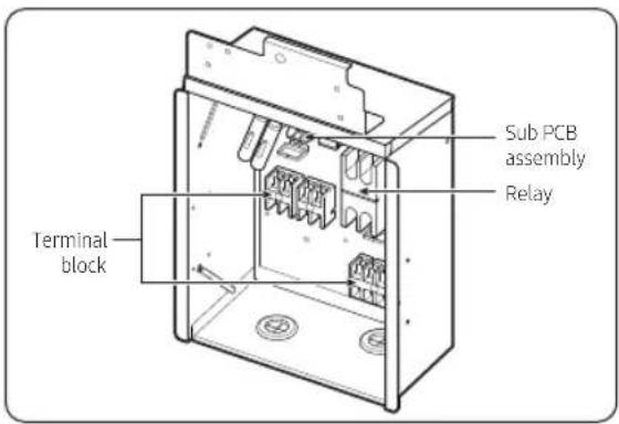
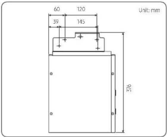
Control box parts diagram
Accessories
| Product Body (1) Installation Guide (1) | |
 |  |
| Bracket Holder (1) M4 x L12 Screw (5) | |
 |  |
Installation
4 English
Control Box Installation
Installing the control box [DVM S2 Series]
1 Fasten the bracket to the control box's body using the supplied screws. The bracket should be installed on the left of the control box.

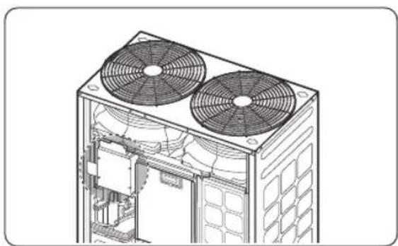
2 Mount the control box in the outdoor unit as below figure.
• Installation in a DVM S2 Small model
3 Fasten the control box to the outdoor unit with supplied screws (3EA) for assembly.
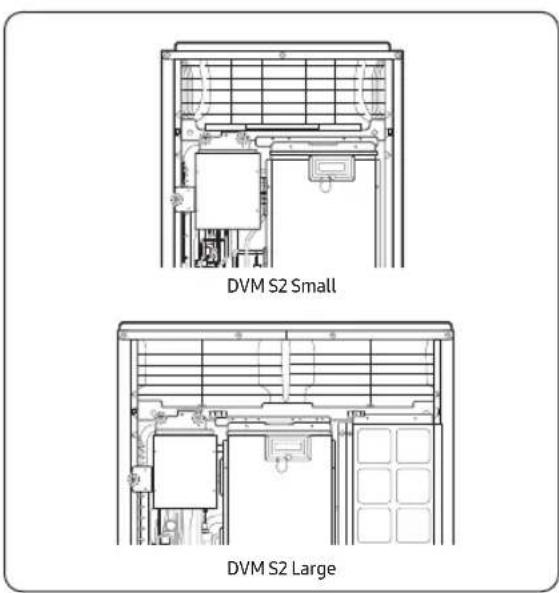
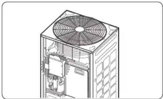
• Installation in a DVM S2 Large model
English 5
Control Box Installation
4 Connect the transmission and power wires between the base heater control box and the outdoor unit control box. Secure the wires with the factory installed wire holders.

※ IMPORTANT
When screwing the terminals together, arrange them back to back so that there will be no gap between each as shown in the figure above.

6 English
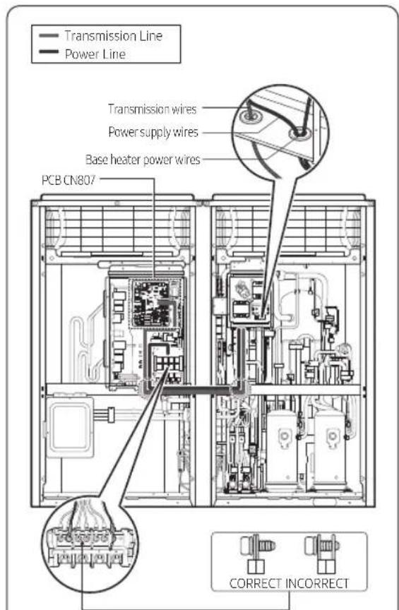
* IMPORTANT
When screwing the terminals together, arrange them back to back so that there will be no gap between each as shown in the figure above.
Connecting the power terminals
- Secure the base heater wires as shown in the figure.
- When wiring the base heater control box, use wire connectors with compression connection.
- Perform wiring using the designated cables. Secure the cables to avoiding external force.
- When fastening the terminals, use a screwdriver and wrench to apply the rated torque.
- Failure to tighten these connections properly may result in a loose connection causing potential overheating and subsequent damage.
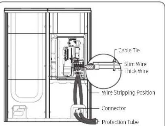
When wiring two cables on a single terminal, separate the crimp terminals up and down to make sure there is no lifting. Place the slim wire up and the thick wire down. Fix the power cable by using cable ties.
| Screw | Tightening torque for terminal (N·m) | Remarks |
| M4 1.2~1.8 | Single phase 220~240V power cable | |
| M8 5 | 5~7.3 | 3 phase 380~415V power cable |
CAUTION
- When stripping the wires, be sure to use the correct tools to prevent damage to the inner wire insulators.
- Have the outer sheath of the indoor unit's power and transmission wires inserted into the electrical system by 20 mm or more.
- Separate the power and communication wires.
English 7



Control Box Installation
Wiring diagram
• AVR-M200GHAX (For 230V) - DVM S2 Small/Large
BASE HEATER CONTROL KIT MAIN CONTROL BOX
![graph TD A["BASE HEATER 1"] --> B["B14 PBA"] C["BASE HEATER 2"] --> D["T/B"] B --> E["M/C"] D --> E E --> F["THERMOSIAT"] F --> G["MAIN PBA"] style A fill:#f9f,stroke:#333 style C fill:#f9f,stroke:#333 style B fill:#ccf,stroke:#333 style D fill:#ccf,stroke:#333 style E fill:#cfc,stroke:#333 style F…](/content/2026/05/897263/images/cf2315a0f4859c029594f91052186c5eeb2b8470a496000684fa902eddce6d76.jpg)
8 English
Configure outdoor unit option settings
When installing Base heater and control box, be sure to enable the Base heater function for the outdoor unit. When installing in modules on modular systems (more than one outdoor unit), enable the function on the main outdoor unit.
Configuring outdoor unit options
[DVM S2 Series]

Installation and configuration settings at the outdoor unit PCB
Configuring the options
1 Press and hold K2 to enter the setup. (the system must be stopped to modify)
- The following appears. If the compressor cut-off setting is enabled, 1 or 2 appears in Segment 4.

- In Segment 1 and Segment 2, the number of the selected option appears.
- In Segment 3 and Segment 4, the setting value of the selected option appears.
2 In the option setup menu, when you shortly press the K1 switch, the values for Segment 1 and Segment 2 change. You can select the desired option.
(e.g. The value for Segment 1 is 2 and the value for Segment 2 is 1.)

3 In the desired option, if you shortly press the K2 switch, the values for Segment 3 and Segment 4 change. You can select the desired option.
(e.g. The value for Segment 3 is 0 and the value for Segment 4 is 1.)
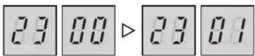
4 After selecting an option, hold the K2 button for 2 seconds. All 7-segment displays blink. If you enter the tracking mode, the option setting is saved.
CAUTION
- If the settings are not set and saved as noted above, the option setting is not saved.
※ If you want to return to the previous setting before saving, press and hold the K1 switch to cancel.
※ If you want to reset to the factory defaults, in the option setting mode, press and hold the K4 switch.
- If you press and hold the K4 switch, all the settings are reset to the factory defaults but the values are not saved yet. Only when the 7-segment display goes to the tracking mode by pressing and holding the K2 switch, the setting is saved.
English 9
Control Box Installation
| Option Entry | Unit SEG1 | SEG2 | SEG3 | SEG4 | Function | |||
| Base Heater Main 2 3 | 0 0 Disabled (Factory default) | |||||||
| 0 1 Enabled | ||||||||
Cautions for base heater and control box
- If the main software version of the Outdoor unit is prior to August 2018, Base Heater setup is unavailable. Update the firmware for your Main PBA(DB92-03752A)
- If the option is not set, an error occurs so normal operation may not be possible.
• To obtain the updated outdoor unit firmware, please reach out to your local Samsung HVAC service or distribution center.
※ While the ODU is in "Base Heater testing mode" or while the base heater is on under normal operation, never touch the heater or parts near the base plate to prevent serious burns.
Test running the base heater
[DVM S2 Series]

After the installation, test run the outdoor unit by using the tact switch.
Test run procedure
1 Test run the base heater by using the K2 button.
- Press the K2 button 14 times to display the following.

2 Check whether the control box relay operates properly.
3 Check whether the surface temperature of the base heater has increased.
- Be sure to use a non-contact thermometer when checking the temperature.
CAUTION
- Do not touch base pan heater as it may cause serious burns.
4 The test run finishes after 3 minutes.
Check items by error code
| Symptom | During the Heat mode or the heater test run, the temperature on the heater does not increase. |
| Cause | 1) Connection error2) Outside temperature sensor error3) Heater power connection error4) Relay operation error |
![graph TD A["The connector is properly connected between the heater control box and outdoor unit control box?"] -->|Yes| B["The outside temperature sensor operates normally? (Not applicable to the test run.)"] A -->|No| C["Check operation after connecting the connector."] B -->|Yes| D["The heater pow…](/content/2026/05/897263/images/0c2b72b99c7bd68492a2ffa2864bc7544549525a82f1a37e5321b9ae06954aa0.jpg)
English 11

Check items by error code
| Symptom The | heater operates normally at the outside temperature of 5 °C or higher? |
| Cause | 1) Test run2) Outside temperature sensor error3) Relay operation error |
![graph TD A["Commissioning is in progress?"] -->|Yes| B["It operates normally."] A -->|No| C["The outside temperature sensor operates normally?"] C -->|No| D["Check operation after removing foreign materials, or connecting or replacing the sensor."] C -->|Yes| E["The relay operates normally?"] E -->|…](/content/2026/05/897263/images/433b5bf07bba8ecfe04900e4e94cfad0de950ac51bc00a4403ac86b969d16b8c.jpg)
12 English

Memo


Appendix
English 13



SAMSUNG


This product is India RoHS compliant

- BASE HEATER CONTROL KIT
- INSTALLATION MANUAL
- CONTENTS
- SAFETY INFORMATION 3
- INSTALLATION 4
- APPENDIX 11
- (APPLICABLE IN COUNTRIES WITH SEPARATE COLLECTION SYSTEMS)
- SAFETY INFORMATION
- WARNING
- CAUTION
- PARTS AND DIMENSIONS
- CONTROL BOX INSTALLATION
- INSTALLING THE CONTROL BOX [DVM S2 SERIES]
- CONNECTING THE POWER TERMINALS
- WIRING DIAGRAM
- CONFIGURE OUTDOOR UNIT OPTION SETTINGS
- CONFIGURING OUTDOOR UNIT OPTIONS
- INSTALLATION AND CONFIGURATION SETTINGS AT THE OUTDOOR UNIT PCB
- CAUTIONS FOR BASE HEATER AND CONTROL BOX
- TEST RUNNING THE BASE HEATER
- AFTER THE INSTALLATION, TEST RUN THE OUTDOOR UNIT BY USING THE TACT SWITCH
- CHECK ITEMS BY ERROR CODE
- MEMO
- SAMSUNG
Brand : SAMSUNG
Model : AVR-M200GHAX
Category : Heating