
DTA113B51 - Software DAIKIN - Free user manual and instructions
Find the device manual for free DTA113B51 DAIKIN in PDF.


| Product Type | Software |
| Brand | Daikin |
| Model | DTA113B51 |
| Version | 1.0 |
| Platform Compatibility | Windows, macOS |
| Language Support | English, French, German, Spanish, Italian, Dutch, Portuguese, Chinese, Japanese, Korean |
| File Format | PDF (manual) |
| File Size | ~5 MB |
| Number of Pages (Manual) | 25 |
| Installation Type | Download |
| Update Mechanism | Automatic via internet |
| Main Functions | HVAC control, scheduling, monitoring, diagnostics |
| User Interface | Graphical UI with touch support |
| Network Support | Ethernet, Wi-Fi |
| Security Features | User authentication, encrypted communication |
| Backup & Restore | Supported |
| Repair & Spare Parts | Not applicable (software); updates available |
| Cleaning & Maintenance | Clean cache and temporary files regularly |
| Warranty | 1 year for updates |
| System Requirements | 2 GB RAM, 1 GHz processor, 500 MB free disk space |
Frequently Asked Questions - DTA113B51 DAIKIN
User questions about DTA113B51 DAIKIN
0 question about this device. Answer the ones you know or ask your own.
Ask a new question about this device
Download the instructions for your Software in PDF format for free! Find your manual DTA113B51 - DAIKIN and take your electronic device back in hand. On this page are published all the documents necessary for the use of your device. DTA113B51 by DAIKIN.
USER MANUAL DTA113B51 DAIKIN
natural_image
Illustration of a white building with green trees and a tall metal tower against a blue sky (no text or symbols)CONTENTS
BEFORE USE....1
SYSTEM OVERVIEWS.... 2
INSTALLATION.... 3
OPERATION....8
APPENDIX 15
Keep this operation manual so that you can refer to it if needed.
Also, if this software is transferred to a new user, make sure to hand over this operation manual to the new user.
BEFORE USE
Thank you for purchasing DS-NET system software. This operation manual contains notes for safe use of the product.
For correct use, be sure to read this manual carefully before use.
*Required System
- PC running in Windows 2000 Professional SP3 or a later version or Windows XP Professional or Home Edition SP2.
- PC equipped with a processor equivalent to Pentium II with a speed of at least 450 MHz (Pentium III at a speed of 600 MHz or higher is recommended)
- Minimum required memory capacity: 128 Mbytes
• Minimum hard disk space: 10 Gbytes - Display: Resolution of 1,024 × 768 dots or above with a minimum of 256 display colors
- Disk drive: CD-ROM drive
- Printer: Printer that can print in A4
- Others: Microsoft Mouse or a compatible pointing device
- Modem: ZOOM Model2949 or Model2948, or U.S. Robotics 56K* V.92 External Faxmodem Model USR995630B
*The required memory capacity and the hard disk space may vary with the system environment.
*The use of a dedicated PC for DS-NET monitoring is recommended. Additional restrictions may occur depending on the user's system environment and usage.
License Agreement
The user acknowledges that the obligations and liabilities of Daikin Industries in respect of the DS-NET software ["the software"] are exhaustively defined in this agreement.
Daikin Industries will not be liable to the user or any third party for any direct, indirect or consequential loss, damage, cost or expense of any kind whatsoever and however caused whether arising under contract, tort [including negligence] or otherwise, including [without limitation] the entire cost of service or repair, loss of or corruption to data, loss of profits or of contracts loss of operation time and loss of goodwill or anticipated savings, even if Daikin Industries has been advised of their possibility.
Good data processing procedure dictates that any software program be thoroughly tested with non-critical data before relying to it.
The user must assume the entire risk of using the software
Microsoft and Windows are either registered trademarks of Microsoft Corporation in the United States and/or other countries. Other company names and product names appearing in the manual are trade trademarks or registered trademarks.
SYSTEM OVERVIEWS
The DS-NET is a light system that performs the remote error monitoring and control of air conditioners installed on each site (e.g., the premises of a small-scale store). Furthermore, adapters installed on sites incorporate a function for local control (e.g., backup and alternate operation control) besides the error monitoring and reporting functions.
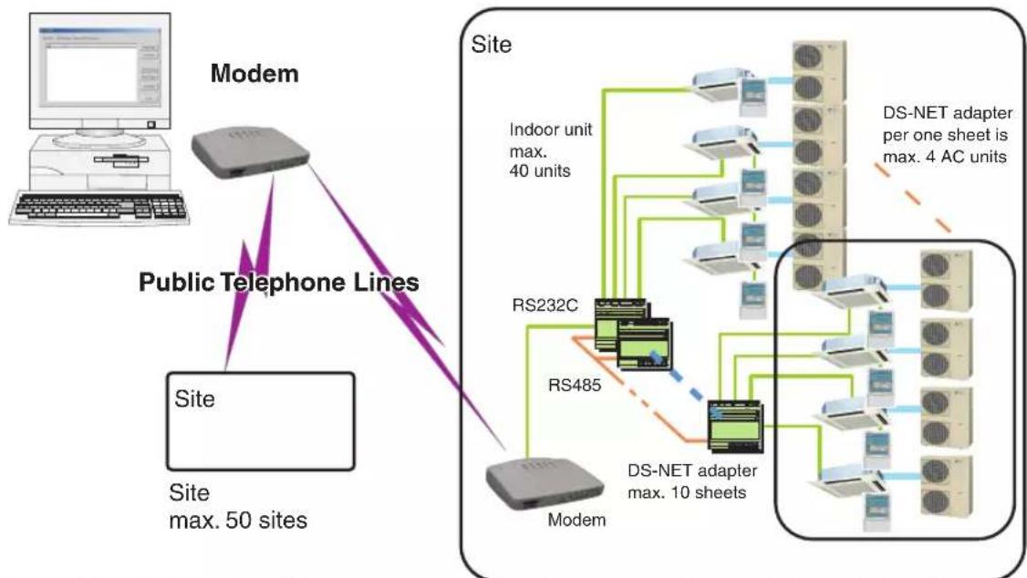
flowchart
graph TD
    A["Modem"] -->|Public Telephone Lines| B["Site"]
    B --> C["Site max. 50 sites"]
    D["DS-NET adapter max. 10 sheets"] --> E["Indoor unit max. 40 units"]
    D --> F["RS232C"]
    D --> G["RS485"]
    D --> H["Modem"]
    H --> I["DS-NET adapter per one sheet is max. 4 AC units"]
Wiring in Site: Perform the wiring and setup of the adapter according to the Installation Manual.
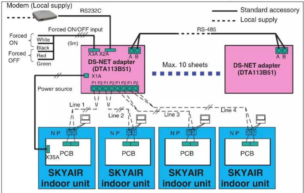
flowchart
graph TD
    A["Modem (Local supply)"] --> B["RS232C"]
    B --> C["Forced ON/OFF input"]
    C --> D["DS-NET adapter (DTA113B51)"]
    D --> E["RS-485"]
    E --> F["DS-NET adapter (DTA113B51)"]
    F --> G["Max. 10 sheets"]
    G --> H["Line 1"]
    G --> I["Line 2"]
    G --> J["Line 3"]
    G --> K["Line 4"]
    H --> L["NP PCB X35A"]
    I --> M["NP PCB"]
    J --> N["NP PCB"]
    K --> O["NP PCB"]
    L --> P["SKYAIR indoor unit"]
    M --> Q["SKYAIR indoor unit"]
    N --> R["SKYAIR indoor unit"]
    O --> S["SKYAIR indoor unit"]
    P --> T["Power source"]
    Q --> U["Power source"]
    R --> V["Power source"]
    S --> W["Power source"]
    T --> X["Power source"]
    style A fill:#f9f,stroke:#333
    style F fill:#f9f,stroke:#333
Air conditioner monitoring and control functions available to DS-NET software
| Item Monitoring Operation | ||
| ON/OFF ○ ○ | ||
| Operation mode (FAN/HEAT/COOL) ○ | ○ | |
| Setting temperature (COOL/HEAT) ○ | ○ | |
| Air volume ○ ○ | ||
| Filter sign ○ ○ | (Reset) | |
| Error code ○ - |
INSTALLATION
1. Contents
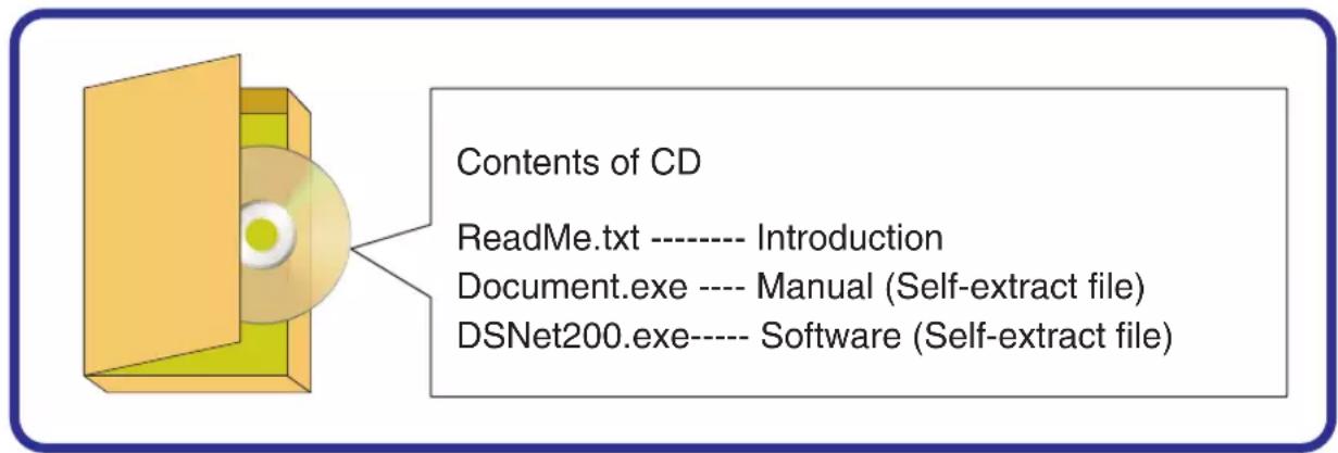
The CD includes this manual and software.
Fig 1-1 Contents of CD
2. Introduction
Before installing the software, make the following checks.
2-1. Disk Remaining Capacity:
Secure a disk capacity of 10 Gbytes for the daily operation of the DS-NET including the maintenance of the log file.
2-2. Windows Version:
The DS-NET supports Windows 2000 Professional SP3 or a later version or Windows XP Professional or Home Edition SP2.
2-3. Power-saving Function:
The DS-NET is a system that operates around the clock and monitors the operation of air conditioners on each site. Do not use the Windows power-saving function to stop the PC automatically.
2-4. Mail Function
The DS-NET has a function to dispatch mail whenever errors are detected. When using this function, check that mail client software has been installed in the PC.
Note:
- The mail client software should be Outlook Express Ver. 6.0 or subsequent ones. Make the following settings for Outlook Express in advance.
- The user needs environment settings for Internet connection and a contract with an Internet service provider. Make proper environment settings to allow mail transmission and reception in Outlook Express.
- Mail transmission from the DS-NET may be blocked if Internet security, firewall, or similar software is installed. Make proper security software settings so that port access made by the DS-NET will not be blocked. When using the mail function of the DS-NET, make the following settings for Outlook Express.
(1) Start Outlook Express and select [Tools], [Options], and the [General] tab. Press the [Make Default] button in [Default Messaging Programs] so that Outlook Express will be set to your default mail handler.
(2) Go to [Virus Protection] in the [Security] tab of the [Options] dialog and uncheck [Warn me when other applications try to send mail as me].
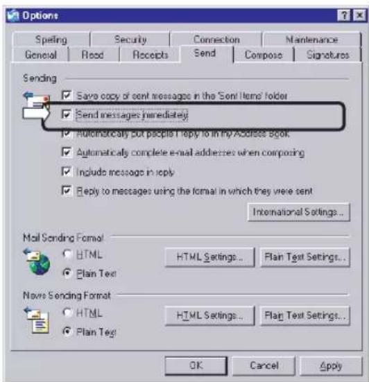
(3) Go to [Sending] in the [Send] tab of the [Options] dialog and uncheck [Send messages immediately].
Fig 2-1 Options (1) Fig 2-2 Options (2)
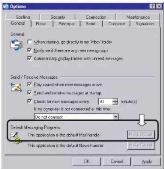
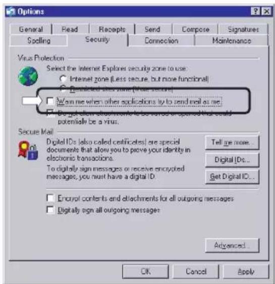
Fig 2-3 Options (3)
3. Modem Settings
3-1. Modem Installation
Connect the recommended modem to the COM1 port of the PC with the PC and modem turned power off. Turn on the modem and PC and start Windows. While the PC is starting, the plug-and-play function will detect the modem automatically. Install the driver then.
Note: In order to use this system, it is necessary to install a modem on each site as well. In order to prevent communication troubles resulting from a problem in the affinity between modems, make sure that the PC and site sides are connected to modems that are the same in model.
3-2. Settings for Location Information
The DS-NET dials according to the dialing method (tone/pulse) in the location information of the PC. Therefore, location information settings are needed.
Location Information
- Double click [Telephone and Modem Options] in [Control Panel].
- Set the following items for the present location information.
- Country/Area
- Long-distance number
• Dialing method (tone/pulse)
Note: If two or more locations are registered, the DS-NET will use the present location information selected.
4. Software Installation
4-1. Installation from CD
Create a folder to install the software if necessary. Execute the DSNET200.exe file on the CD then. A dialog to input the destination folder name will appear. Input the folder name, if necessary, and click [OK]. The destination folders will be created, and the file will be copied. A screen will appear twice to register the component. Click [OK] each time.
Note 1: The software can be installed at high speed if the file is copied on the hard disk.
Note 2: Manually uninstall and delete the software and shortcut menu of version 1.00 if the software has been installed.
Note 3: As a countermeasure against system drive (C: drive) problems, the creation of the D: drive is recommended along with software installation to the D: drive, which does not guarantee the evasion of all problems though. Periodical data backup in an external memory storage unit or CD-R is recommended.
Fig 4-1 Startup Image
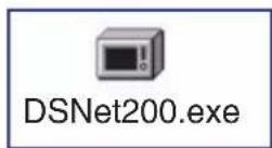
Fig 4-2 Dialog (Designation of Destination)
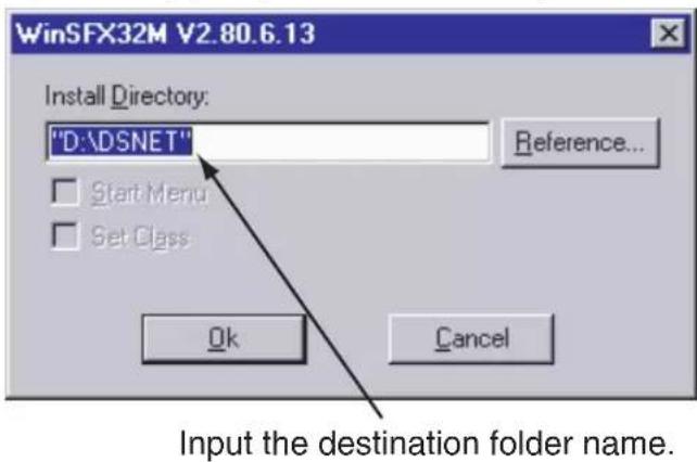
Fig 4-3 Results of Component Unregistration
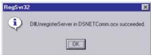
Fig 4-4 Results of Component Registration
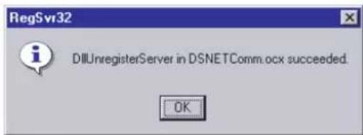
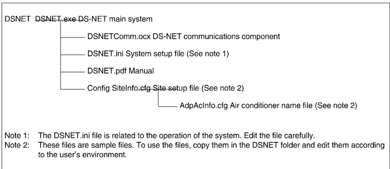
Fig 4-5 Installation File Configuration
flowchart
graph TD
    A["DSNET"] --> B["DSNET.exe DS-NET main system"]
    B --> C["DSNETComm.ocx DS-NET communications component"]
    C --> D["DSNET.ini System setup file (See note 1)"]
    D --> E["DSNET.pdf Manual"]
    E --> F["Config SiteInfo.cfg Site setup file (See note 2)"]
    F --> G["AdpAcInfo.cfg Air conditioner name file (See note 2)"]
DSNET.exe serves as the execution software of the DS-NET system. Create a shortcut on the desktop or in an appropriate place if necessary. At that time, be sure to designate the DSNET.exe destination folder as the work folder.
4-2. Editing Setup File
The DS-NET enables initial settings by just creating the minimum required information, thus saving engineering effort.
There is a config folder including the samples of setup files in the destination folder of the DS-NET. The config folder includes the following sample files. Refer to the files and edit them according to the user's environment. These files are in text format and can be edited in NotePad, MS Word, WordPad, etc.
Note: Before creating data, it is recommended to fill the required items into a datasheet to be attached to Appendix A and edit the setup file based on the datasheet.
DSNET.ini
Initial setup file (inevitable)
SiteInfo.cfg
Setup file related to site (inevitable)
AdpACInfo.cfg
Adapter/air conditioner name setup file (optional)
4-2-1. Initial Setup File (DSNET.ini)
This file is an operation setup file of DS-NET and consists of sections, keys, and values.
Note: Do not edit any sections or keys. Do not edit any part other than those explained in this manual.
![[SYSTEM] MODEM=Zoom 56K Data Fax Dualmode Modem PnP TELNO=B2 SOUND=Sound.wav LOG=1 PATH=DAT MAIL_VALID=0 MAIL_ADDRESS=********@daikin.co.jp [COMM] AUTO_ANSWER=1](/content/2026/05/896943/images/4ce147a2bfe91d60695bc4686529a7cce3220c4c0334e0f0b4cf3b138d10a661.jpg)
| Section Key Value | ||
| SYSTEM | MODEM | Modem name (32 bytes max.) |
| TELNO | Own phone number (See note 1) | |
| SOUND | Sound file (Relative path)(See note 2) | |
| LOG | General log file(0: Disable/1: Enable) | |
| PATH | General log output folder(Relative path) | |
| MAIL_VALID | Mail dispatch(0: Disable/1: Enable) (See note 3) | |
| MAIL_ADDRESS | Destination mail address | |
| COMM | AUTO_ANSWER | Auto answer(0: Disable/1: Enable) |
Note 1: Specify the telephone number consisting of the prefix "B," followed by figures. (Hyphens cannot be specified.)
Example: TELNO=B1234567890
Note 2: Specify a sound file to generate sound whenever errors are detected.
Note 3: The mail dispatch function is enabled only if MAIL_VALID is set to 1, AUTO_ANSWER is set to 1, and the mail address is set for MAIL_ADDRESS.
4-2-2. Setup File Related to Site (Sitelinfo.cfg)
This file is used to register the adapter and air conditioner names to be displayed on the DS-NET.
This file is in the following format divided with commas.
Each line serves as the definition of a single site.
Note: Do not include commas in character strings.
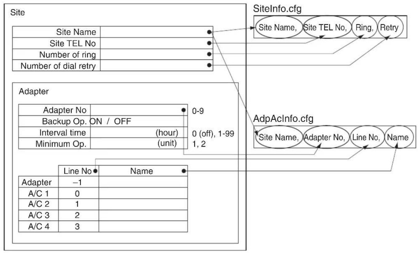
SiteName, Site TEL No, Ring, Retry
SiteName: Site name (See note 1) (32 bytes max.)
Site TEL No: Telephone number of site (See note 2) (30 characters max.)
Ring: Number of rings until the line is put through. (1 to 3)
Retry: Number of redial times (0 to 99)
Note 1: A user-defined alphanumeric character string can be specified.
Note 2: Specify the telephone number consisting of figures and hyphens.
[Important] The telephone number needs to be unique in the same system.
Note 3: The maximum number of sites is 50.
Setting example
SITE_001,123-4567-1111,1,2
SITE_002,123-4567-1234,1,2
4-2-3. Adapter/Air Conditioner Name Setup File (AdpAcInfo.cfg)
This file is in the following format divided with commas.
Note: Do not use commas for character strings.
SiteName, Adapter No, LineNo, Name
SiteName: Site name (See note 1) (32 bytes max.)
Adapter No: Connected adapter number (0 to 3)
LineNo: Adapter port number to which the air conditioner is connected (See note 2).
Name: Name (See note 3) (16 bytes max.)
Note 1: The site name set for SiteInfo.cfg must be used.
Note 2: If 0, 1, 2, or 3 is specified for LineNo, the air conditioner name for each line will be set. If -1 is specified, the adapter name will be set.
Note 3: A user-defined alphanumeric character string can be specified.
Setting example
SITE_001,0,-1,ADP1-1,
SITE_001,0,0,AC1-1,
SITE_001,0,1,AC1-2,
Note: The system will automatically assign a name if this file does not exist or if no name is set for the adapter or air conditioner.
4-3. Checks by Starting DS-NET
4-3-1. Start and Initial Settings
a) When the DS-NET system starts, the DS-NET will automatically check whether the setup file is correct. If there is any setting mistake, the DS-NET does not start but displays an error message.
Correct the setup file according to the message.
b) When the DS-NET system starts normally, log on the system from the [Logon] screen.
There will be no password at the initial start of the system. Click the [System ...] button and make the following settings.
Periodic Scan Settings
Set the periodic scan time and the sites to be scanned.
Initial Password Settings
Register the password. After registration, log in with this password.
Do not forget the registered password.
c) Configuration Scan
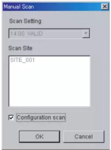
Select [Scanning] and [Start] so that the [Manual Scan] dialog will appear. Check the [Configuration Scan] and click the [OK] button. Execute the scanning of all the registered sites and collect the latest information. Unless the [Configuration Scan] is checked.
Unless [Configuration Scan] is checked, the normal scanning of the site appearing in [Scan Site] will be performed with no collation of setup information.
A DS-NET setting mistake or a site (adapter) problem may be considered if an error (e.g., a communication error) occurs in the process of scanning. In that case, check the cause of the error.
Note: If new registration or any change is made, be sure to perform an configuration scan to match the setup conditions with each site's settings. The configuration scan will require a period determined by the number of adapters on all the sites multiplied by approximately 10 seconds.
d) Detailed Settings
Make system settings and adapter settings for each site.
e) Backup Recommendation
After all items are set and confirmed, stop the DS-NET once. Back up the DS-NET destination folder and subsequent folders then.
Note: The DS-NET accumulates the latest information and log data during daily monitoring. In order not to lose the information due to accidents, such as PC failures, it is recommended to back up the information on a daily basis. Each type of DS-NET file can be copied while the DS-NET is running.
4-3-2. Checks on Startup Failure
Mistakes in DS-NET settings or site adapter and modem connections are considered if the DS-NET does not run.
- No communication at all: Mistakes in connections to the COM1 port of the modem or power supply are considered.
- No communication with specified sites: Mistakes in DS-NET settings for site phone numbers are considered.
- Communication error in specific air conditioner: Mistakes in line number settings are considered.
- The following jobs are required after adding or removing air conditioners or making wiring changes. [Site side]
Reset the power supply to the DS-NET. [PC side]
- Finish the DS-NET.
- Delete the corresponding site from Sitelinfo.cfg.
- Start and finish the DS-NET. This clears only data on the corresponding site in DSNET.dat.
- Register the corresponding site with Sitelinfo.cfg again.
- Start the DS-NET again.
- Execute configuration scan to update the status.
OPERATION
1. Start and Stop
The DS-NET starts by double clicking the icon shown in Fig. 1-1 or the linking shortcut icon. When the DS-NET starts, the main screen shown in Fig. 2-1 will appear.
Fig. 1-1 Icon

DSNet.exe
To quit the DS-NET, click the [Exit] button on the main screen.
Usually, keep the DS-NET running around the clock. While the DS-NET is not running, site errors occurring cannot be monitored.
Note: This prevents people other than the administrator finishing the DS-NET, the DS-NET cannot be finished while the DS-NET system is logged off.
2. Main Screen
When the DS-NET starts, the main screen will appear and the DS-NET will go into monitoring operation.
Fig. 2-1 Main Screen
Present time
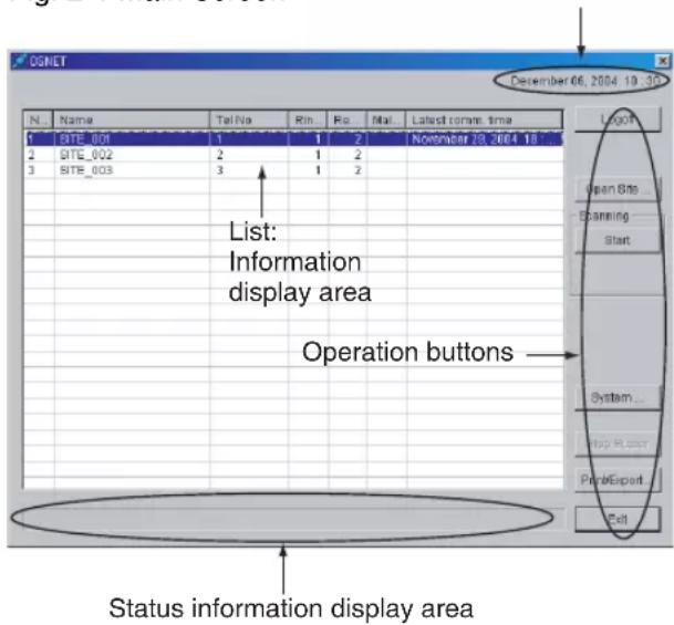
List width adjustments: The display width of each item can be adjusted by shifting the item boundaries.
Status domain: Information, such as information on functions being executed, is displayed.
The following information will be listed and displayed.
No: Running number
Name: Site name
Tel No.: Phone number of site
Ring Count: The number of rings until the adapter answers the call
ReDial: The number of redials at the time of reporting from the adapter
Malfunction code: An error code for the detection of an air conditioner error (see note 1)
Latest comm.time: The latest communication time (see note 2)
Note 1: Refer to Appendix D for the malfunction code in detail. If an error is detected in a line, the line will be displayed in red.
Note 2: All information displayed is obtained during the latest communication time. Therefore, the information on the screen may not be always in agreement with the present air conditioner conditions.
Operation button: A button to perform a variety of operations. For details, refer to subsequent explanation.
Logon/Logoff: Performs user authentication.
Open Site...: Displays a list of air conditioners on the user-specified site.
Scanning: Performs manual scan and configuration scan.
System...: Performs system settings.
Stop Buzzer: Stops the error alarm.
Print/Export...: Prints the list or exports the list in file format.
Exit: Quits the DS-NET system.
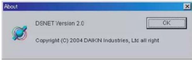
Version Information
The version information will appear by clicking the right mouse button on the title bar of the main screen. Advise your DAIKIN representative of the version information when making inquiries.
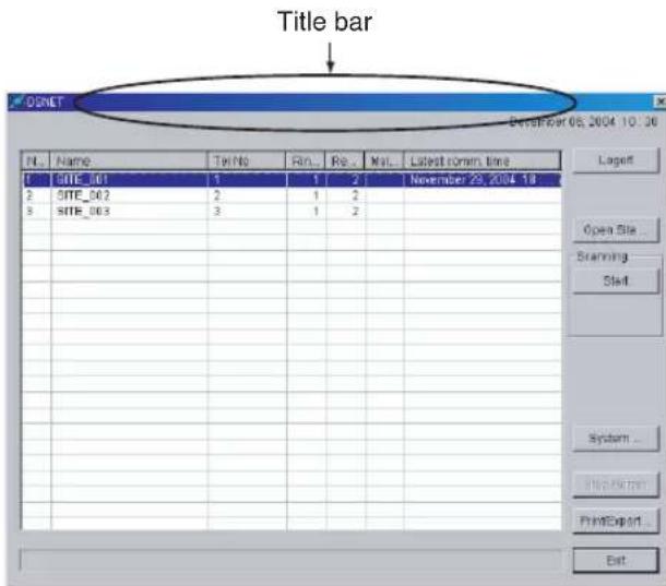
Fig 2-2 Version Information
2-1. Logon
Perform user authentication in order to acquire the authority for the operation of the DE-NET system. By logging on, all operations will be possible. Only the list of site information can be displayed while the DS-NET system is logged off. The password is set as a system setup item.
Fig 2-3 Logon Dialog
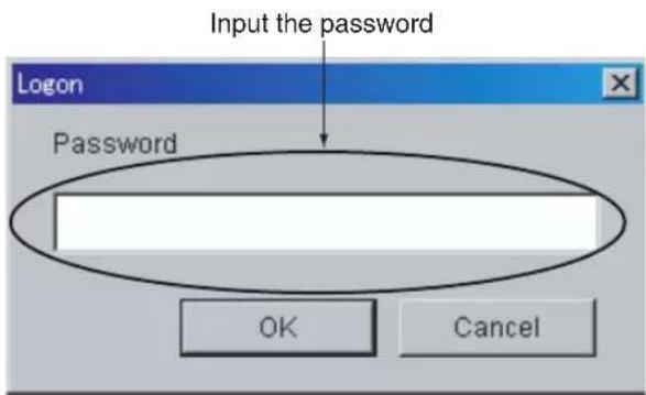
Note 1: The user can log on without entering the password immediately after the system is installed. Set the password as a system setup item.
Note 2: If the user forgets the password, delete the line of the [PASSWORD] key in the DSNET.ini file and restart DSNET.exe. The DS-NET will start by default with no password. Set a new password then.
2-2. Display of Air Conditioner List
By selecting a site and clicking the [Open Site...] button, the list of information on the air conditioners on the selected site will appear.
For details, refer to 3. Air Conditioner List Screen.
2-3. Error Monitoring
Error monitoring is performed through manual scanning or automatic scanning performed at the preset hours in the system setup. Furthermore, error monitoring is performed based on reporting from the site. Moreover, with the mail dispatch function enabled, an error report will be sent to a registered mail address automatically if an error occurs.
2-3-1. Periodic Automatic Scanning
The automatic scanning of registered sites will start at specified hours a maximum of four times for each day. The message telling that the status area is being scanned will appear during automatic scanning.
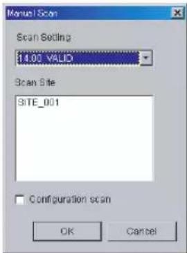
2-3-2. Manual Scanning
Sites can be manually scanned provided that the sites are registered for periodic automatic scanning.
Select [Scanning] and [Start] so that the [Manual Scan] dialog will be appear.
By selecting a specified hour for periodic automatic scanning and click [OK], the scanning of registered sites will start.
Fig 2-4 Manual Scan Dialog
2-3-3. Error Monitoring through Reporting from Sites
Air conditioner information is collected from reports dispatched from each site under the following conditions.
• Periodical report (Once/day)
• Detection of air conditioner errors
Note 1: Periodic reporting hours need to be registered with the adapter of the site in advance.
Note 2: The DS-NET Adapter is not provided with a clock backup function.
Execute a configuration scan to make clock settings at the time of power restoration after a power failure or power shutoff.
By executing the configuration scan, the clock will be automatically adjusted to coincide with the built-in clock of the monitoring PC. Therefore, be sure to adjust the built-in clock of the monitoring PC correctly as well.
Note 3: The tolerance of the built-in clock on the DS-NET Adapter is a maximum of ±20 seconds on a daily basis.
Execute a configuration scan regularly on a daily basis to adjust the clock.
2-3-4. Dispatching Error Mails
When the mail dispatch function is enabled, mail messages will be sent automatically whenever errors are found.
Refer to Appendix G for the mail format.
Note 1: While in scanning operation, no air conditioner or adapter can be individually operated or set.
Note 2: No power failure or restoration can be monitored.
Note 3: Malfunctions and communication errors detected may be restored through communication (manual control, automatic or manual scanning, and error reporting) after the occurrence of the malfunctions and communication errors.
Note 4: To enable the mail dispatch function, make settings by referring to 2.4 Mail Function and 4-2-1 Initial Setup File (DS-NET.ini). in the Installation Section.
2-4. System Settings
Click the [System] button to make whole system settings.
Fig 2-5 System Setup Dialog
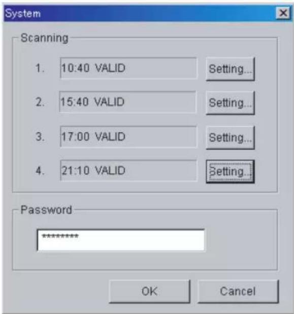
Fig 2-6 Automatic Scanning Setup Dialog
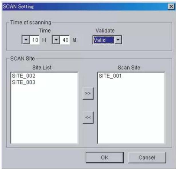
Scanning: Displays the starting hours of automatic scanning. A maximum of four starting hours can be specified for each day.
Setting...: Displays an automatic scanning setup dialog.
Password: Sets the user's password used at logon time (see note 1).
Time of scanning: Sets the starting hours of automatic scanning and the validity or invalidity of automatic scanning (see note 2).
Scan Site: Resisters the site where automatic scanning is performed at specified hours.
Note 1: Do not forget the password that is set.
Note 2: The specification of hours depends on the number of air conditioners. If starting hours are specified four times for each day, it is recommended to take sufficient intervals (e.g., six-hours intervals) between them. If the next scan time comes before the completion of the previous scan that started at the specified hour, the scan will start on completion of the previous scan.
2-5. Print/Export
The site list and the air conditioner list can be printed or exported in file format.
Refer to the Appendix B for the printing form and export format.
Caution: The displayed information on the screen when the function is executed will be printed or exported in file format. The contents of this information may differ from the present air conditioner conditions. If the present information is needed, perform manual scanning and print the information or export the information in file format.
Fig 2-7 Printing Dialog
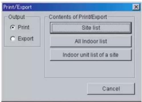
Output: Specifies an output method (printing or export).
Contents of Print/Export:
Site list: Prints or exports the site list in file format.
All Indoor list: Prints the air conditioner list or exports the list in file format.
Indoor unit list of a site: Prints the air conditioner list of the user-specified site or exports the list in file format.
Note: To print the list, a printer in A4 size supported by Windows is required.
3. Air Conditioner List Screen
By clicking [Open Site...] on the main screen, the air conditioner list screen of the user-specified site will appear.
Fig. 3-1 Air Conditioner List Screen
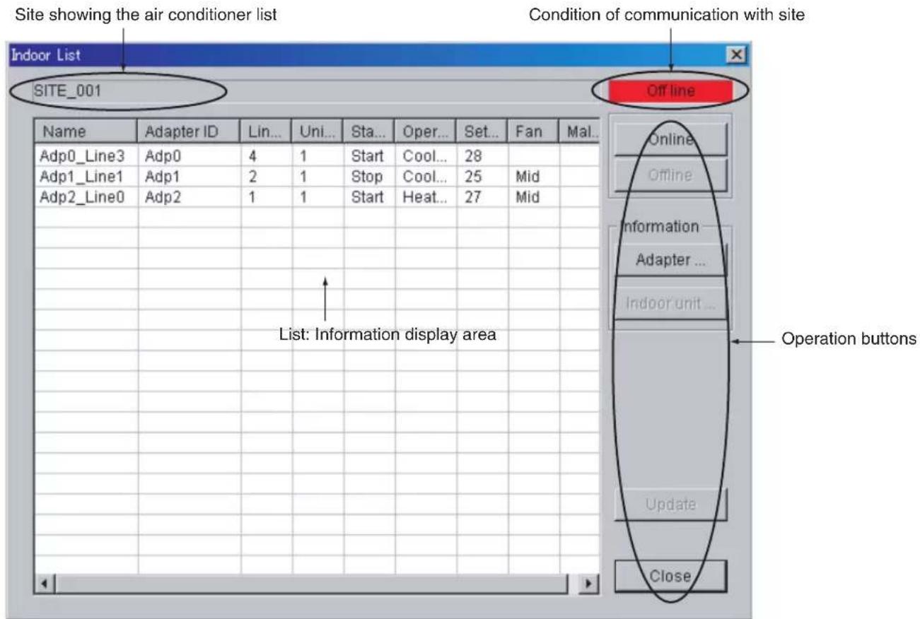
Contents of list displayed: The following information is displayed.
Name: Air conditioner name
Adapter ID: Unique ID assigned to each adapter
Line No: Port number of the adapter where the air conditioner system is connected
Unit Count: The number of air conditioner units
Start/Stop: Operating state
Operation Mode: Operation mode
Setpoint: Set temperature
Fan: Airflow rate
Malfunction code: An error code for the detection of an air conditioner error (See note 1)
Note 1: Refer to Appendix D for the malfunction code in detail. If an error is detected in a line, the line will be displayed in red.
Operation button: A button to perform a variety of operations. For details, refer to the subsequent explanation.
Online/Offline: Connects to or disconnects from the user-specified site.
Information:
Adapter...: Makes remote control settings for the adapter.
Indoor unit...: Makes remote control settings for the air conditioner.
Update: Updates air conditioner information.
Close: Closes the air conditioner list screen.
3-1. Online/Offline
Connect the DS-NET to a site by clicking [Online] when updating remote settings for the air conditioner, adapter, and air conditioner information of the site. When closing the air conditioner list screen, disconnect communication with the site by clicking [Offline].
3-2. Remote Settings/Information Display
3-2-1. Adapter Remote Settings/Information Display
Adapter information on the user-specified site is displayed and remote settings for the site are made as explained below.
Remote settings are performed online only.
Adapter settings are made by specifying a set value and clicking the [OK] button.
Fig 3-2 Adapter Remote Setting Dialog
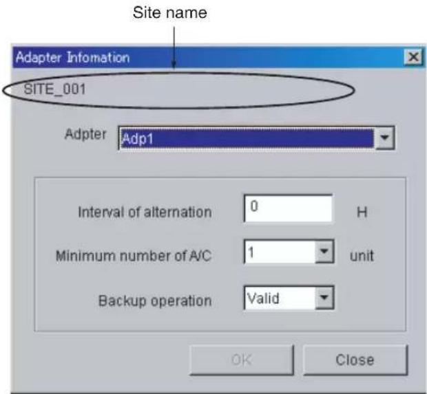
Adapter:
Selects an adapter from the adapter list to make settings for the adapter or display the adapter.
Interval of alternation:
Specifies the interval of operation alternation. The interval can be set between 1 and 99. If 0 is specified, operation alternation will be disabled. The settings in the DS-NET adapter made with the service function of the remote controller will be updated.
Minimum number of A/C:
Specifies the minimum number of air conditioner units to be operated.
The number can be set between 1 and 3.
The settings in the DS-NET adapter made with the service function of the remote controller will be updated.
Backup operation:
Enables or disables the backup operation function.
3-2-2. Air Conditioner Remote Settings/Information Display
Information on an air conditioner is displayed and remote settings for the air conditioner are made by selecting the air conditioner from the list.
Remote settings are possible online only.
Air conditioner settings are made by specifying a set value and clicking the [OK] button.
Caution:
Air conditioning settings are made by clicking [OK]. The air conditioner may not be set to the specified conditions soon, in which case the specified contents will not be reflected on the air conditioner list screen or detailed information. On the other hand, as a result of the execution of local control, such as operation alternation made with adapter settings, the air conditioner may be controlled immediately after the remote control operation of the air conditioner. Gather information by manual updating a few minutes after important control is made.
Fig 3-3 Air Conditioner Remote Setup Dialog
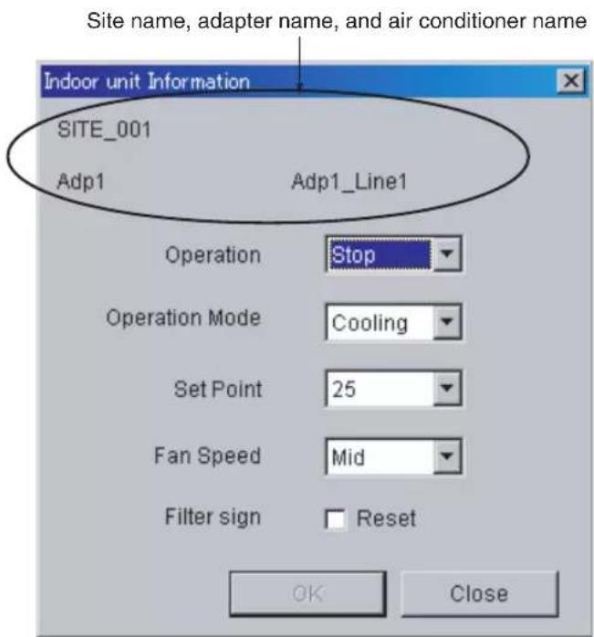
Operation: Operates or stops the air conditioner.
Operation mode: Specifies the operation mode (See note 1).
Set point: Makes temperature settings for cooling and heating (See note 1).
Fan: Sets the airflow rate (See note 1).
Note 1: The operable ranges (items) of information vary with the air conditioner. The items that are not operable will be displayed thinly on the screen.
3-3. Update
Air conditioner information will be updated by clicking [Update].
[Update] is available online only.
Note: While air conditioner information is being updated, remote settings for air conditioners or adapters will not be available.
3-4. Close
The air conditioner list screen will be closed by clicking the [Close] button.
The [Close] button is available offline only.
4. Log
The present conditions of the air conditioners on all sites will be saved as a log at the timing of collecting air conditioner information (through automatic or manual scanning, periodic reporting, or error reporting).
Note: Refer to Appendix C for the log file format.
The log will be saved in a file (see note 1) on a monthly basis in the DAT folder in the installed folder.
The decision of saving or not saving data in the log is set in the DSNET.ini file.
Note 1: The file of April 2005 will be DS-NET200504.csv.
Note: If a disk capacity of 10 Gbytes required for the DS-NET is secured, log files can be created for a few years without any special arrangements. In order to cope with problems, such as PC system failures, however, it is recommended to make file backups and delete unnecessary old files periodically.
APPENDIX
Appendix A Data Sheet Sample
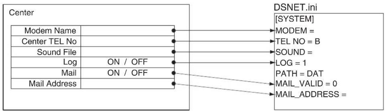
flowchart
graph LR
    A["Center"] --> B["Modem Name"]
    A --> C["Center TEL No"]
    A --> D["Sound File"]
    A --> E["Log ON / OFF"]
    A --> F["Mail ON / OFF"]
    A --> G["Mail Address"]
    H["DSNET.ini"] --> I["MODEM ="]
    H --> J["TEL NO = B"]
    H --> K["SOUND ="]
    H --> L["LOG = 1"]
    H --> M["PATH = DAT"]
    H --> N["MAIL_VALID = 0"]
    H --> O["MAIL_ADDRESS ="]
flowchart
graph TD
    A["SiteInfo.cfg"] --> B["Site Name"]
    A --> C["Site TEL No"]
    A --> D["Number of ring"]
    A --> E["Number of dial retry"]
    F["Adapter"] --> G["Adapter No"]
    F --> H["Backup Op. ON / OFF"]
    F --> I["Interval time (hour)"]
    F --> J["Minimum Op. (unit)"]
    K["AdpAclInfo.cfg"] --> L["Site Name, Adapter No, Line No, Name"]
    M["Adapter"] --> N["-1"]
    O["A/C 1"] --> P["0"]
    Q["A/C 2"] --> R["1"]
    S["A/C 3"] --> T["2"]
    U["A/C 4"] --> V["3"]
Appendix B Print/Export Format
B-1 Printing Site List
The following items (the same as those on the main screen) are printed in A4 portrait format.
With the export function, the contents of printing will be output in a CSV format file.
The date, time, and page number will be printed on the bottom of the sheet on the left-hand side.
| NO Item TypeRemarks | |||
| 1 | N o . n u m | e r i c | |
| 2 Name string Site name | |||
| 3 Tel No. string Site Tel No. | |||
| 4 Ring Count. numeric | |||
| 5 Redial numeric | |||
| 6 Malfunction code | string | ||
| 7 Latest comm. time | string | ||
B-2 Printing Air Conditioner List
The following items (in addition to the information on the air conditioner list screen) will be printed in A4 landscape format.
With the export function, the contents of printing divided with commas will be output in a CSV format file.
The date, time, and page number will be printed on the bottom of the sheet on the left-hand side.
| NO Item TypeRemarks | |||
| 1 Site name | string | ||
| 2 Adp. No. numeric | 1-10 | ||
| 3 Adapter ID | string | ||
| 4 Line No. | numeric | 1-4 | |
| 5 A/C name | string | ||
| 6 Unit Count | numeric | ||
| 7 Start/Stop | string | ||
| 8 Operation Mode | string | ||
| 9 Set Point | string | ||
| 10 Room Temp. | numeric | Room temperature | |
| 11 Fan | string | ||
| 12 Filter Sign | string | ||
| 13 Malfunction code | string | ||
| 14 Op. time | numeric | Operation time | |
| 15 Comp time | numeric | Compressor operation time | |
| 16 Comp sw | numeric | Compressor switching time | |
| 17 Backup | string | Automatic backup operation | |
| 18 Alt | numeric | Interval of alternation | |
| 19 Mini A/C | numeric | Minimum number of A/C | |
| 20 Latest Comm. time | string | ||
Appendix C Log File Format
The log does not collect data for data measurement but records data collected at the time of air conditioner status communication. Such data is used as a reference for the communication history of the air conditioner.
The log file with the following items in a single line is added to the file (DsNetYYYYMM.csv) of each month. A new file will be automatically created when the month changes.
| NO Item TypeRemarks | |||
| 1 Time stamp | "yyyy/mm/ddhh:mm:ss" | ||
| 2 Site Tel No. string | |||
| 3 Adapter ID numeric 1 - 10 | |||
| 4 Line No. numeric 1 - 4 | |||
| 5 Site Name string | |||
| 6 Adapter Name string | |||
| 7 A/C Name string | |||
| 8 Unit 0 Malfunction Code string | 000: No error | ||
| : | : | ||
| 23 | Unit15 Malfunction Code | string | 000:No error |
| 24 | Filter Sign | string | ON, OFF |
| 25 | Operation | string | Start, Stop |
| 26 | Room Temperature numeric | ||
| 27 | Comm status | string | 0000: No error |
| 28 | Operation Mode | string | Fan, Heating, Cooling |
| 29 | Operation time | numeric | |
| 30 | Compressor operation time | numeric | |
| 31 | Compressor switching time | numeric | |
| 32 | Set point | numeric | |
| 33 | Fan | numeric 0 - 5 | |
| 34 | Number of Indoor unit | numeric 1 - 16 | |
| 35 | Number of dial rety | numeric 0 - 99 | |
| 36 | Number of ring | numeric 1 - 15 | |
| 37 | Automatic backup operation | string | ON, OFF |
| 38 | Interval of alternation | numeric 0,1 - 99 | |
| 39 | Minimum number of A/C | numeric 1, 2, 3 | |
Each item is divided by a comma.
Appendix D Malfunction Code
Malfunction Code
Two-character code sets following the character "F", "W", or "A" are malfunction code sets used for air conditioners. These codes vary with the air conditioner in use. After code conversion according to the below table, refer to the Instruction Manual of the air conditioner for details. Refer to the Operation Manual of the air conditioner for details. The following code sets beginning with "R", "A", "U", or "S" are malfunction code sets peculiar to the DS-NET.
| Code | Meaning Remedy | ||
| Site List Air Conditioner List | |||
| R-- | F** Failure code (Malfunction) | After code conversion according to the attached table, refer to the Manual of the Air Conditioner. | |
| W** Warning code (Malfunction) | After code conversion according to the attached table, refer to the Manual of the Air Conditioner. | ||
| A** Attention code (Malfunction) | After code conversion according to the below table, refer to the Manual of the Air Conditioner. Note: A02 is “adapter dropout.” | ||
| R00 Adapter communication error Check the adapter. | |||
| R01 | Air conditioner communication error | Check the air conditioner. | |
| R00 R02 | Filter sign noticeNotice at the turn-on timing of the filter sign | Check the filter. | |
| A-- A02 Adapter dropout Check the adapter. | |||
| U-- U00 Air conditioner (line) dropout Check the air conditioner. | |||
| U-- U01 Air conditioner (unit) dropout Check the air conditioner. | |||
| S00 | Sight communication error | Check the telephone number of the site (setting file) and the modem. | |

| Tens digit code | Division code |
| 1 | A |
| 2 | C |
| 3 | E |
| 4 | H |
| 5 | F |
| 6 | J |
| 7 | L |
| 8 | P |
| 9 | U |
| Ones digit code | Content code |
| 0 | 0 |
| 1 | 1 |
| 2 | 2 |
| 3 | 3 |
| 4 | 4 |
| 5 | 5 |
| 6 | 6 |
| 7 | 7 |
| 8 | 8 |
| 9 | 9 |
| 10 | A |
| 11 | H |
| 12 | C |
| 13 | J |
| 14 | E |
| 15 | F |
Appendix E Adapter Setting
Make the following adapter settings for the DS-NET system.
Refer to the Installation Manual and Operation Manual of the Adapter for the setting method.
| Service Mode No | Unit No. | Item No | Values | Remarks |
| 20 | 15 | 0 3 See note | 1 | |
| 6 | 2 | |||
| 21 | 0 2 See note | 2 | ||
| 2 | 2 | |||
| 3 1 See note | 2 | |||
| 22 | 0 1 See note | 2 | ||
| 1 1 See note | 2 | |||
| 2 1 See note | 2 | |||
| 3 1 See note | 2 | |||
| 4 1 See note | 2 | |||
| 5 2 See note | 2 | |||
| 50 | 0 0 See note | 2 | ||
| 1 0 See note | 2 | |||
| 2 | 0 | |||
| 3 | 2 | |||
| 4 | 0 | |||
| 5 | 0 | |||
| 6 | 0 | |||
| 7 | 0 | |||
| 8 | 0 | |||
| 9 0-9 See note | 3 |
Note 1: Do not change this value.
Note 2: These values will change when the DS-NET comes into operation. Set these values as initial values before operating the DS-NET.
Note 3: Set the adapter address between 0 and 9. Be sure to set 0 for the parent adapter (the adapter connected to the modem).
Appendix F Local Control
Automatic Alternate Operation
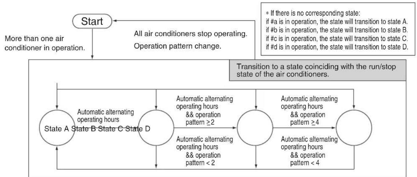
According to the number of air conditioner systems connected and the minimum guaranteed number of units in operation, all the air conditioners are operated and stopped at certain intervals (alternate operation intervals) so that the operating hours of each air conditioner can be equalized.
Automatic alternate operation of the air conditioners is not performed while air conditioner errors are detected.
When the air conditioners are in automatic alternate operation, the air conditioners may not respond to the remote controller or remote instructions.
Automatic alternate operation pattern
| Operation Pattern | Number of air conditioner systems connected | Minimum guaranteed number of air conditioners operated |
| 1 2 line 1 unit | ||
| 2 3 line 1 unit | ||
| 3 | 2 | |
| 4 4 line 1 unit | ||
| 5 | 2 | |
| 6 | 3 |
State of each operating pattern
| Operation Pattern No. | State A | State B | State C | State D |
| 1 #a=ON, #b=OFF | #a=OFF, #b=ON | |||
| 2 | #a=ON, #b=OFF#c=OFF | #a=OFF, #b=ON#c=OFF | #a=OFF, #b=OFF#c=ON | |
| 3 | #a=ON, #b=ON#c=OFF | #a=OFF, #b=ON#c=ON | #a=ON, #b=OFF#c=ON | |
| 4 | #a=ON, #b=OFF#c=OFF, #d=OFF | #a=OFF, #b=ON#c=OFF, #d=OFF | #a=OFF, #b=OFF#c=ON, #d=OFF | #a=OFF, #b=OFF#c=OFF, #d=ON |
| 5 | #a=ON, #b=ON#c=OFF, #d=OFF | #a=OFF, #b=ON#c=ON, #d=OFF | #a=OFF, #b=OFF#c=ON, #d=ON | #a=ON, #b=OFF#c=OFF, #d=ON |
| 6 | #a=ON, #b=ON#c=ON, #d=OFF | #a=OFF, #b=ON#c=ON, #d=ON | #a=ON, #b=OFF#c=ON, #d=ON | #a=ON, #b=ON#c=OFF, #d=ON |
a: Air conditioner system with the smallest remote controller line number recognized.
b: !
c:
d: Air conditioner system with the largest remote controller line number recognized.
State transition
flowchart
graph TD
    Start["Start"] -->|More than one air conditioner in operation.| StateA["State A State B State C State D"]
    StateA -->|Automatic alternating operating hours && operation pattern ≥2| StateD
    StateD -->|Automatic alternating operating hours && operation pattern < 2| StateA
    StateD -->|Automatic alternating operating hours && operation pattern ≥4| StateE
    StateE -->|Automatic alternating operating hours && operation pattern < 4| StateD
    StateA -->|All air conditioners stop operating. Operation pattern change.| End
    StateB -->|Transition to a state coinciding with the run/stop state of the air conditioners.| End
    StateC -->|* If there is no corresponding state: if #a is in operation, the state will transition to state A. if #b is in operation, the state will transition to state B. if #c is in operation, the state will transition to state C. if #d is in operation, the state will transition to state D.| End
Note:
When the forced operation signal is input, all air conditioners will be in operating mode, and the air conditioners will start forced operation, to which priority is given over automatic alternate operation, the remote controller, or remote instructions. The foregoing applies to the forced stop signal in the similar manner. Higher priority is given to the forced stop signal over the forced operation signal.
Backup Control Operation
Overview
If an air conditioner comes to a stop due to a power failure or malfunction (excluding any alarm or warning), another air conditioner will be operated in order to keep the number of air conditioners in operation.
If the air conditioner that has come to a stop starts operating again, one of the air conditioners in operation will be stopped so as to keep the number of air conditioners operating before the occurrence of the power failure or malfunction.
Remote controller operation may be ignored while the backup control operation is active.
Sequential Start Control Operation
Overview
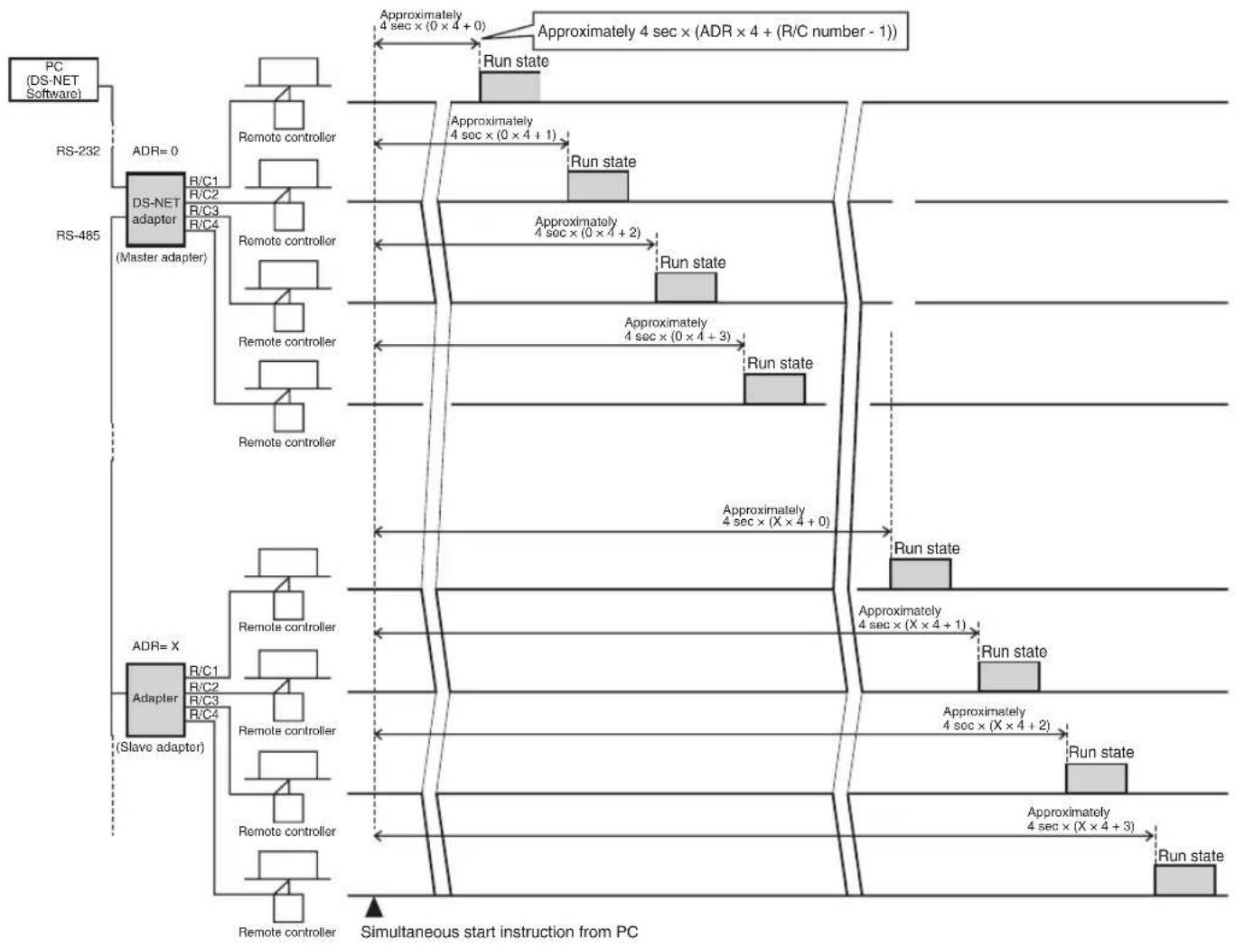
A very high starting current will flow immediately after the DS-NET software transmits a start instruction simultaneously to all the air conditioners connected to the DS-NET Adapter units and the air conditioners start operating together. The sequential start control operation adjusts the start timing of each air conditioner to suppress the starting current and prevent all the air conditioners from starting simultaneously.
- The sequential start control operation is available only if the system is connected to the PC to execute the DS-NET software.
- The sequential start control operation does not work for Personal Home Use with the GSM modem employed.
- The sequential start control operation adjusts the start timing of each air conditioner and prevents all the air conditioners from starting simultaneously.
- The DS-NET software cannot make setting changes to enable or disable the sequential start control operation. Use the remote controller in service mode instead. For details, refer to the Installation Manual.
Start Timing of Sequential Start Control Operation
- The DS-NET Adapter starts each of the connected air conditioners in sequence at approximately 4-second intervals after a delay according to the adapter address (ADR) when the start instruction is received.
- The delay time is a minimum guaranteed time, which may be extended according to the connected system or operation timing.
flowchart
graph TD
    A["PC (DS-NET Software)"] --> B["RS-232"]
    B --> C["DS-NET adapter (Master adapter)"]
    C --> D["Remote controller"]
    D --> E["Run state"]
    E --> F["Approximately 4 sec × (0 × 4 + 0)"]
    F --> G["Run state"]
    G --> H["Approximately 4 sec × (ADR × 4 + (R/C number - 1))"]
    H --> I["Run state"]
    I --> J["Approximately 4 sec × (0 × 4 + 1)"]
    J --> K["Run state"]
    K --> L["Approximately 4 sec × (0 × 4 + 2)"]
    L --> M["Run state"]
    M --> N["Approximately 4 sec × (0 × 4 + 3)"]
    N --> O["Run state"]
    O --> P["Run state"]
    P --> Q["Approximately 4 sec × (X × 4 + 0)"]
    Q --> R["Run state"]
    R --> S["Approximately 4 sec × (X × 4 + 1)"]
    S --> T["Run state"]
    T --> U["Approximately 4 sec × (X × 4 + 2)"]
    U --> V["Run state"]
    V --> W["Approximately 4 sec × (X × 4 + 3)"]
    W --> X["Run state"]
    X --> Y["Run state"]
    Y --> Z["Run state"]
    Z --> AA["Run state"]
    AA --> AB["Run state"]
    AB --> AC["Run state"]
    AC --> AD["Run state"]
    AD --> AE["Run state"]
    AE --> AF["Run state"]
    AF --> AG["Run state"]
    AG --> AH["Run state"]
    AH --> AI["Run state"]
    AI --> AJ["Run state"]
    AJ --> AK["Run state"]
    AK --> AL["Run state"]
    AL --> AM["Run state"]
    AM --> AN["Run state"]
    AN --> AO["Run state"]
    AO --> AP["Run state"]
    AP --> AQ["Run state"]
    AQ --> AR["Run state"]
    AR --> AS["Run state"]
    AS --> AT["Run state"]
    AT --> AU["Run state"]
    AU --> AV["Run state"]
    AV --> AW["Run state"]
    AW --> AX["Run state"]
    AX --> AY["Run state"]
    AY --> AZ["Run state"]
    AZ --> BA["Run state"]
    BA --> BB["Run state"]
    BB --> BC["Run state"]
    BC --> BD["Run state"]
    BD --> BE["Run state"]
    BE --> BF["Run state"]
    BF --> BG["Run state"]
    BG --> BH["Run state"]
    BH --> BI["Run state"]
    BI --> BJ["Run state"]
    BJ --> BK["Run state"]
    BK --> BL["Run state"]
    BL --> BM["Run state"]
    BM --> BN["Run state"]
    BN --> BO["Run state"]
    BO --> BP["Run state"]
    BP --> BQ["Run state"]
    BQ --> BR["Run state"]
    BR --> BS["Run state"]
    BS --> BT["Run state"]
    BT --> BU["Run state"]
    BU --> BV["Run state"]
    BV --> BW["Run state"]
Forced Start/Stop Operation
Overview
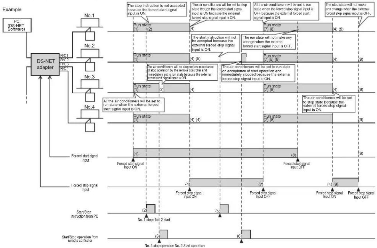
Air conditioners can be forcibly started or stopped with an external forced start or forced stop signal input into the DS-NET Adapter.
Priority will be given to the forced stop operation if forced start and forced stop signals are input simultaneously.
Contact type: Normally closed
Detection condition: Level sensing
Forced Start Operation
When the forced start signal is ON, all air conditioners connected to the DS-NET Adapter will be set to run state. Furthermore, if a stop instruction is transmitted from the PC or stop operation is performed by the remote controller while a forced start signal is ON, priority will be given to the forced start operation and the air conditioners will operate.
The air conditioners started with a forced start signal turned ON will continue operating when the forced start signal is turned OFF.
The following conditions, however, apply.
- If a forced stop signal is ON, priority will be given to the forced stop operation.
- If a malfunction occurs, priority will be given to the stop operation activated with the malfunction detected.
Forced Stop Operation
When a forced stop signal is ON, all air conditioners connected to the DS-NET Adapter will be stopped.
Furthermore, if a start instruction is transmitted from the PC or start operation is performed by the remote controller while a forced stop signal is ON, priority will be given to the forced stop operation and the air conditioners will be stopped.
The air conditioners stopped with a forced stop signal turned ON will be continuously in the stop state when the forced stop signal is turned OFF.
The following conditions, however, apply.
- The forced stop operation takes precedence over the forced start operation.
Start/Stop Operation Timing with Forced Start and Forced Stop Signals
flowchart
graph TD
    A["Start/Stop operation from remote controller"] --> B["Forced stop signal Input"]
    B --> C["Run state (1)"]
    C --> D{Forced stop signal Input ON}
    D --> E["Run state (7)"]
    E --> F{Forced stop signal Input OFF}
    F --> G["Run state (7)"]
    G --> H{Forced stop signal Input ON}
    H --> I["Run state (7)"]
    I --> J{Forced stop signal Input OFF}
    J --> K["Run state (7)"]
    K --> L{Forced stop signal Input ON}
    L --> M["Run state (7)"]
    M --> N{Forced stop signal Input ON}
    N --> O["Run state (7)"]
    O --> P{Forced stop signal Input ON}
    P --> Q["Run state (7)"]
    Q --> R{Forced stop signal Input ON}
    R --> S["Run state (7)"]
    S --> T{Forced stop signal Input ON}
    T --> U["Run state (7)"]
    U --> V{Forced stop signal Input ON}
    V --> W["Run state (7)"]
    W --> X{Forced stop signal Input ON}
    X --> Y["Run state (7)"]
    Y --> Z{Forced stop signal Input ON}
    Z --> AA["Run state (7)"]
    AA --> AB{Forced stop signal Input ON}
    AB --> AC["Run state (7)"]
    AC --> AD{Forced stop signal Input ON}
    AD --> AE["Run state (7)"]
    AE --> AF{Forced stop signal Input ON}
    AF --> AG["Run state (7)"]
    AG --> AH{Forced stop signal Input ON}
    AH --> AI["Run state (7)"]
    AI --> AJ{Forced stop signal Input ON}
    AJ --> AK["Run state (7)"]
    AK --> AL{Forced stop signal Input ON}
    AL --> AM["Run state (7)"]
    AM --> AN{Forced stop signal Input ON}
    AN --> AO["Run state (7)"]
    AO --> AP{Forced stop signal Input ON}
    AP --> AQ["Run state (7)"]
    AQ --> AR{Forced stop signal Input ON}
    AR --> AS["Run state (7)"]
    AS --> AT{Forced stop signal Input ON}
    AT --> AU["Run state (7)"]
    AU --> AV{Forced stop signal Input ON}
    AV --> AW["Run state (7)"]
    AW --> AX{Forced stop signal Input ON}
    AX --> AY["Run state (7)"]
    AY --> AZ{Forced stop signal Input ON}
    AZ --> BA["Run state (7)"]
    BA --> BB{Forced stop signal Input ON}
    BB --> BC["Run state (7)"]
    BC --> BD{Forced stop signal Input ON}
    BD --> BE["Run state (7)"]
    BE --> BF{Forced stop signal Input ON}
    BF --> BG["Run state (7)"]
    BG --> BH{Forced stop signal Input ON}
    BH --> BI["Run state (7)"]
    BI --> BJ{Forced stop signal Input ON}
    BJ --> BK["Run state (7)"]
    BK --> BL{Forced stop signal Input ON}
    BL --> BM["Run state (7)"]
    BM --> BN{Forced stop signal Input ON}
    BN --> BO["Run state (7)"]
    BO --> BP{Forced stop signal Input ON}
    BP --> BQ["Run state (7)"]
    BQ --> BR{Forced stop signal Input ON}
    BR --> BS["Run state (7)"]
    BS --> BT{Forced stop signal Input ON}
    BT --> BU["Run state (7)"]
    BU --> BV{Forced stop signal Input ON}
    BV --> BW["Run state (7)"]
    BW --> BX{Forced stop signal Input ON}
    BX --> BY["Run state (7)"]
    BY --> BZ{Forced stop signal Input ON}
    BZ --> CA["Run state (7)"]
    CA --> CB{Forced stop signal Input ON}
    CB --> CC["Run state (7)"]
    CC --> CD{Forced stop signal Input ON}
    CD --> CE["Run state (7)"]
    CE --> CF{Forced stop signal Input ON}
    CF --> CG["Run state (7)"]
    CG --> CH{Forced stop signal Input ON}
    CH --> CI["Run state (7)"]
    CI --> CJ{Forced stop signal Input ON}
    CJ --> CK["Run state (7)"]
    CK --> CL{Forced stop signal Input ON}
    CL --> CM["Run state (7)"]
    CM --> CN{Forced stop signal Input ON}
    CN --> CO["Run state (7)"]
    CO --> CP{Forced stop signal Input ON}
    CP --> CQ["Run state (7)"]
    CQ --> CR{Forced stop signal Input ON}
    CR --> CS["Run state (7)"]
    CS --> CT{Forced stop signal Input ON}
    CT --> CU["Run state (7)"]
    CU --> CV{Forced stop signal Input ON}
    CV --> CW["Run state (7)"]
    CW --> CX{Forced stop signal Input ON}
    CX --> CY["Run state (7)"]
    CY --> CZ{Forced stop signal Input ON}
    CZ --> DA["Run state (7)"]
    DA --> DB{Forced stop signal Input ON}
    DB --> DC["Run state (7)"]
    DC --> DD{Forced stop signal Input ON}
    DD --> DE["Run state (7)"]
    DE --> DF{Forced stop signal Input ON}
    DF --> DG["Run state (7)"]
    DG --> DH{Forced stop signal Input ON}
    DH --> DI["Run state (7)"]
    DI --> DJ{Forced stop signal Input ON}
    DJ --> DK["Run state (7)"]
    DK --> DL{Forced stop signal Input ON}
    DL --> DM["Run state (7)"]
    DM --> DN{Forced stop signal Input ON}
    DN --> DO
(1) Forced start signal input: All the air conditioners will be set to run state when this signal is ON. (2) Forced start signal input: The step instruction from the PC will not be accepted because this sign
(2) Forced start signal input: The stop instruction from the PC will not be accepted because this signal is ON. (3) Forced start signal input: Stop operation from the remote controller will be accepted once but the
(b) Closed start signal input. Stop operation from the remote controller will be accepted once but the system will be immediately set to run state because this signal is ON.
(4) Forced stop signal input: All the air conditioners in operation will be stopped when this signal is ON.
(5) Forced stop signal input: The start instruction from the PC will not be accepted because this signal is ON
(6) Forced stop signal input: Start operation from the remote controller will be accepted once but the custom will be immediately set in stop state because this signal is ON.
(7) Forced slot signal input: All the air conditioners will be set to run state when this signal input is OFF.
(7) Forced stop signal input. All the air conditioners will be set to turn because forced start signal input is ON
(8) Forced start signal input: The run state will not change regardless of whether this signal is OFF or not.
(9) Forced stop signal input: The stop state will not change when this signal is OFF
Appendix G Mail Format
A mail message in the following format will be transmitted at the time of error detection.
Subject: DS-NET Error
Body:
[Date]: Time of occurrence
Site: Site name
Adapter or Indoor: Adapter name or air conditioner name
Code: Malfunction code (Unit No. of air conditioner)
Adapter name or air conditioner name display is selected according to the type of error.
In the case of a site error (an error in communication with the site), no adapter name or air conditioner name will be described.
A unit number will be added after the malfunction code only if the information on the error requires the malfunction code. If a number of errors occur simultaneously, the contents of the errors will be described in the single mail message.
Example
Subject: DS-NET Error
From: Monitor system's mail address
To: Client's mail address
[Date]:2004/11/22 09:56
[Date]:2004/11/22 09:57
DAIKIN INDUSTRIES, LTD.
Head office:
Umeda Center Bldg., 4-12, Nakazaki-Nishi 2-chome,
Kita-ku, Osaka, 530-8323 Japan
Tokyo office:
JR Shinagawa East Bldg., 18-1, Konan
2-chome, Minato-ku, Tokyo, 108-0075 Japan
- CONTENTS
- BEFORE USE
- For correct use, be sure to read this manual carefully before use.
- License Agreement
- SYSTEM OVERVIEWS
- INSTALLATION
- Contents
- Introduction
- 2-1. Disk Remaining Capacity:
- 2-2. Windows Version:
- 2-3. Power-saving Function:
- 2-4. Mail Function
- Note:
- Modem Settings
- 3-1. Modem Installation
- 3-2. Settings for Location Information
- Location Information
- Software Installation
- 4-1. Installation from CD
- 4-2. Editing Setup File
- 4-2-1. Initial Setup File (DSNET.ini)
- 4-2-2. Setup File Related to Site (Sitelinfo.cfg)
- 4-2-3. Adapter/Air Conditioner Name Setup File (AdpAcInfo.cfg)
- Setting example
- 4-3. Checks by Starting DS-NET
- 4-3-1. Start and Initial Settings
- Periodic Scan Settings
- Initial Password Settings
- 4-3-2. Checks on Startup Failure
- OPERATION
- Start and Stop
- Main Screen
- 2-1. Logon
- 2-2. Display of Air Conditioner List
- 2-3. Error Monitoring
- 2-3-1. Periodic Automatic Scanning
- 2-3-2. Manual Scanning
- 2-3-3. Error Monitoring through Reporting from Sites
- 2-3-4. Dispatching Error Mails
- 2-4. System Settings
- 2-5. Print/Export
- Air Conditioner List Screen
- 3-1. Online/Offline
- 3-2. Remote Settings/Information Display
- 3-2-1. Adapter Remote Settings/Information Display
- Adapter:
- Interval of alternation:
- Minimum number of A/C:
- Backup operation:
- 3-2-2. Air Conditioner Remote Settings/Information Display
- Caution:
- 3-3. Update
- 3-4. Close
- Log
- APPENDIX
- Appendix B Print/Export Format
- B-1 Printing Site List
- B-2 Printing Air Conditioner List
- Appendix C Log File Format
- Appendix D Malfunction Code
- Malfunction Code
- Appendix E Adapter Setting
- Appendix F Local Control
- Automatic Alternate Operation
- a: Air conditioner system with the smallest remote controller line number recognized.
- b: !
- c:
- d: Air conditioner system with the largest remote controller line number recognized.
- Backup Control Operation
- Overview
- Sequential Start Control Operation
- Start Timing of Sequential Start Control Operation
- Forced Start/Stop Operation
- Forced Start Operation
- Forced Stop Operation
- Appendix G Mail Format
- Example
- DAIKIN INDUSTRIES, LTD.
Brand : DAIKIN
Model : DTA113B51
Category : Software