
BRP069C51 - Régulateur DAIKIN - Free user manual and instructions
Find the device manual for free BRP069C51 DAIKIN in PDF.


| Product Type | Regulator (Thermostat/Controller) |
| Brand | Daikin |
| Model | BRP069C51 |
| Dimensions (approx.) | 85 x 130 x 28 mm |
| Weight (approx.) | 0.25 kg |
| Power Supply | 24 V AC (50/60 Hz) or 2 x AA batteries |
| Display | LCD with backlight |
| Communication | Modbus RTU (RS-485) or Wi-Fi (optional) |
| Temperature Range | 5 °C to 40 °C (setpoint) |
| Inputs | 1 x NTC temperature sensor |
| Outputs | 1 x relay (normally open) |
| Main Functions | Temperature control, scheduling, frost protection, holiday mode |
| Installation | Wall mounting, 2-wire or 4-wire connection |
| Maintenance | Clean with dry cloth; battery replacement (if applicable) |
| Safety | CE marked, RoHS compliant; overheat protection |
| Spare Parts / Repairability | Battery compartment lid; replaceable temperature sensor |
| Warranty | 2 years (subject to terms) |
Frequently Asked Questions - BRP069C51 DAIKIN
User questions about BRP069C51 DAIKIN
0 question about this device. Answer the ones you know or ask your own.
Ask a new question about this device
Download the instructions for your Régulateur in PDF format for free! Find your manual BRP069C51 - DAIKIN and take your electronic device back in hand. On this page are published all the documents necessary for the use of your device. BRP069C51 by DAIKIN.
USER MANUAL BRP069C51 DAIKIN
Installer reference guide
Wireless LAN connecting adapter BRP069C41
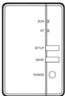
BRP069C41
Table of contents
1 About this document 3
2 Specific installer safety instructions 4
3 About the adapter 5
3.1 Components.... 5
3.2 Basic parameters.... 5
3.3 Compatibility 5
4 About the box 6
4.1 To unpack the adapter 6
5 Installation 7
5.1 Precautions when installing the adapter.... 7
5.2 Overview: Installation 7
5.3 Preparing the installation site.... 7
5.3.1 Installation site requirements 7
5.4 Connecting the electrical wiring.... 8
5.4.1 Overview of electrical connections.... 8
5.4.2 About connecting the electrical wiring 8
5.4.3 Precautions when connecting the electrical wiring.... 9
5.4.4 To connect the adapter with the unit 9
5.5 Closing the adapter.... 10
5.5.1 To close the adapter 10
5.6 Mounting the adapter 11
5.6.1 About mounting the adapter 11
5.6.2 To mount the adapter 11
5.7 Opening the adapter.... 12
5.7.1 About opening the adapter.... 12
5.7.2 To open the adapter 12
6 Starting up the system 13
7 Configuration 14
7.1 To install the ONECTA app.... 14
7.2 To configure the adapter 14
8 Hand-over to the user 15
9 Troubleshooting 16
9.1 Overview: Troubleshooting 16
9.1.1 Symptom: The LEDs do not turn on when the adapter is connected to the unit and the unit is powered ON 16
9.1.2 Symptom: The adapter is NOT responding to interaction with the indoor unit.... 16
9.1.3 Symptom: Nothing happens when the adapter is in AP mode 16
1 About this document
Target audience
Authorised installers
Documentation set
This document is part of a documentation set. The complete set consists of:
■ General safety precautions:
- Safety instructions that you must read before installing
- Format: Paper (in the box of the indoor unit)
- Installation manual:
- Installation instructions
- Format: Paper (supplied in the kit)
- Installer reference guide:
- Installation instructions, configuration, application guidelines, ...
- Format: Digital files on https://www.daikin.eu. Use the search function 🔒 to find your model.
■ Declaration of conformity:

INFORMATION: Declaration of conformity
Hereby, Daikin Industries Czech Republic s.r.o. declares that the radio equipment type BRP069C41 is in compliance with the Directive 2014/53/EU and S.I. 2017/1206: Radio Equipment Regulations 2017. The original declaration of conformity is available on https://www.daikin.eu. Use the search function 🔒 to find the declaration of conformity of your unit.

INFORMATION
For details on specifications, setting methods, FAQ, troubleshooting tips and the latest version of this manual, visit app.dalkineurope.com.
Latest revisions of the supplied documentation may be available on the regional Daikin website or via your dealer.
The original documentation is written in English. All other languages are translations.
2 Specific installer safety instructions
Always observe the following safety instructions and regulations.
Installation (see "5 Installation" [▶ 7])

DANGER: RISK OF ELECTROCUTION
- Turn off the power supply before installing the adapter.
- Do NOT handle the adapter with wet hands.
- Do NOT let the adapter get wet.
- Do NOT disassemble, modify or repair the adapter.
- Grip the connector when disconnecting the connection cable.
- Turn OFF the power supply in case the adapter gets damaged.

DANGER: RISK OF ELECTROCUTION
Do NOT turn on the power supply before you have connected the electrical wiring, closed the adapter, and mounted it to the indoor unit.

DANGER: RISK OF ELECTROCUTION
Before opening the adapter, turn OFF the power to the indoor unit.
Hand over to the user (see "8 Hand-over to the user" [▶ 15])

DANGER
- Do NOT disassemble, modify, or repair the adapter. This can cause fire, electrical shock, or injury.
- Do NOT allow the adapter to get wet or use it when bathing or doing similar activities with water. This can cause electrical shock or fire.
- Do NOT use the adapter near medical equipment, or persons using cardiac pacemakers or defibrillators. This can cause life-threatening electromagnetic interference.
- Do NOT use the adapter near auto-control equipment such as automatic doors or fire alarm equipment. This can cause accidents due to erroneous equipment behaviour.
- In case of abnormal odour or sound, overheating, or smoke coming out of the adapter, immediately disconnect the indoor unit from its power supply. Otherwise, this can lead to fire or malfunction. If this happens, consult your dealer.
- In case you drop or damage the adapter, disconnect the indoor unit from its power supply. Otherwise, this can lead to fire or malfunction. If this happens, consult your dealer.
3 About the adapter
Wireless LAN adapter to connect the heat pump system to the Daikin Cloud via the internet, allowing for control of the heat pump system with the ONECTA app.

INFORMATION
For option model names BRP069C51, BRP069C81 and BRP069C82, wireless LAN adapter inside is BRP069C41.
3.1 Components
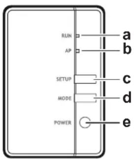
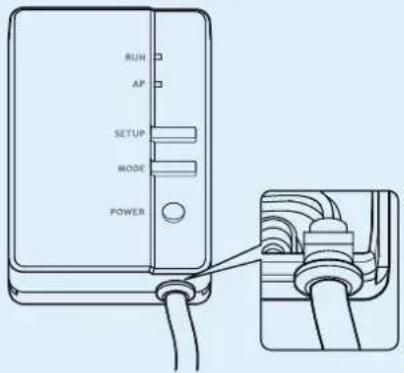
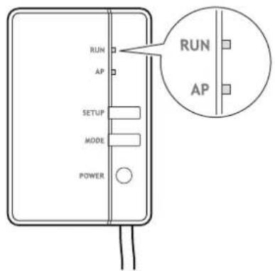
a RUN lamp (orange). Lights when connecting to a router (wireless LAN access point).
b AP lamp
c SETUP button. Use when connecting to a router (wireless LAN access point).
d MODE button
e POWER button. Turns the WLAN adapter ON/OFF when pressed.
3.2 Basic parameters
| Parameter Value | |
| Frequency range 2400 MHz~2483.5 MHz | |
| Radio protocol IEEE 802.11b/g/n | |
| Radio frequency channel 13 ch | |
| Output power 13 dBm | |
| Effective radiated power 15 dBm (11b) / | 14 dBm (11g) / 14 dBm (11n) |
| Power supply DC 14 V/ 16 V / 100 mA |
3.3 Compatibility
Make sure the indoor unit is compatible for use with the adapter. For the latest details about installation of the adapter and applicable units, visit app.daikineurope.com.
4 About the box
Keep the following in mind:
- At delivery, the unit MUST be checked for damage. Any damage MUST be reported immediately to the claims agent of the carrier.
- Bring the packed unit as close as possible to its final installation position to prevent damage during transport.
- Prepare in advance the path along which you want to bring the unit to its final installation position.
4.1 To unpack the adapter
1 Open the box.
2 Take out the adapter BRP069C41 from the option kit box (BRP069C51, BRP069C81 or BRP069C82).
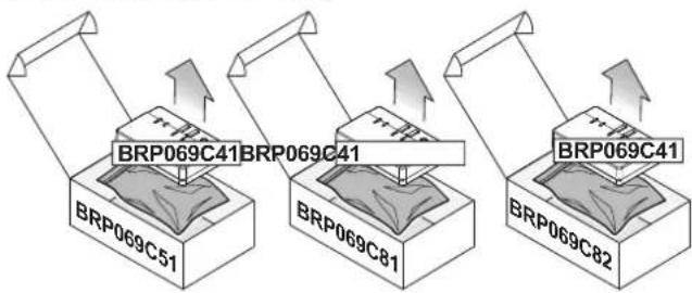
flowchart
graph TD
    A["BRP069C41"] --> B["BRP069C51"]
    C["BRP069C41"] --> D["BRP069C81"]
    E["BRP069C41"] --> F["BRP069C82"]
3 Separate the accessories.
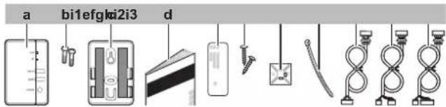
a Adapter BRP069C41
b Screws (M3×8) for the adapter
c Adapter holder with double face tape
d Installation manual
e Serial number sticker (SSID, KEY, MAC)
f Mounting screws for the holder (M3×16)
g Cable tie holder
h Cable tie
i1 For BRP069C51: connection cable to X801A
i2 For BRP069C81: connection cable to X35A + X50A (type 1)
i3 For BRP069C82: connection cable to X35A + X50A (type 2)
5 Installation
5.1 Precautions when installing the adapter

DANGER: RISK OF ELECTROCUTION
- Turn off the power supply before installing the adapter.
- Do NOT handle the adapter with wet hands.
- Do NOT let the adapter get wet.
- Do NOT disassemble, modify or repair the adapter.
- Grip the connector when disconnecting the connection cable.
- Turn OFF the power supply in case the adapter gets damaged.
5.2 Overview: Installation
The installation of the adapter consists of the following stages:
1 Connecting the electrical wiring;
2 Closing the adapter;
3 Mounting the adapter to the unit.

INFORMATION
Where to connect the electrical wiring on the indoor unit, and where to mount the adapter, depends on the type of indoor unit. For more information, see the addendum book for optional equipment of the indoor unit.
5.3 Preparing the installation site
Choose an installation location with sufficient space to transport the unit in and out of the site.
Do NOT install the unit in places often used as work place. In case of construction works (e.g. grinding works) where a lot of dust is created, the unit MUST be covered.
5.3.1 Installation site requirements
The adapter is designed to be mounted to the indoor unit, in dry, indoor locations only.
Do NOT install the adapter in the following places:
- In places where it is exposed to direct sunlight.
- In places where it is near a heat source.
- In places where it is exposed to a source of steam.
- In places where it is exposed to machine oil vapour.
5.4 Connecting the electrical wiring
5.4.1 Overview of electrical connections
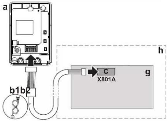
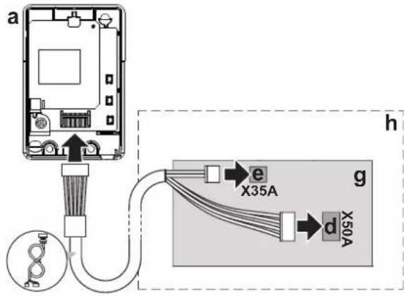
BRP069C51BRP069C81
BRP069C82
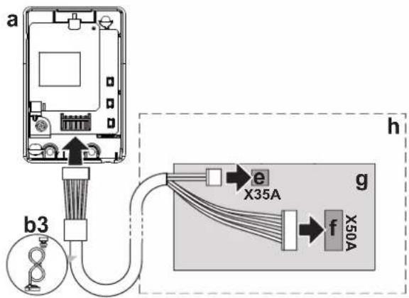
a Wireless LAN adapter BRP069C41
b1 BRP069C51 connection cable
b2 BRP069C81 connection cable
b3 BRP069C82 connection cable
c PCB port X801A
d PCB port X50A (type 1)
e PCB port X35A
f PCB port X50A (type 2)
g Indoor unit PCB
h Indoor unit
5.4.2 About connecting the electrical wiring
Typical workflow
Connecting the electrical wiring typically consists of the following stages:
1 Connecting one end of the connection cable to the indoor unit;
2 Connecting the other end of the connection cable to the adapter.
5.4.3 Precautions when connecting the electrical wiring

INFORMATION
Also read the precautions and requirements in the following chapters:
- General safety precautions
- Preparation

DANGER: RISK OF ELECTROCUTION
Do NOT turn on the power supply before you have connected the electrical wiring, closed the adapter, and mounted it to the indoor unit.
5.4.4 To connect the adapter with the unit
1 Separate the upper casing from the lower casing.
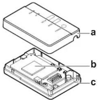
a Upper casing
b Adapter PCB
c Lower casing
2 Connect the indoor unit side connector to the indoor unit PCB port.
BRP069C51: PCB port X801A
- BRP069C81 and BRP069C82: X35A and X50A
3 Connect the adapter side connector to the adapter.
Connection cable for BRP069C51:

a Indoor unit side connector X801A
b Adapter side connector
Connection cable for BRP069C81:

a Indoor unit side connector X35A
b Indoor unit side connector X50A (type 1)
c Adapter side connector
Connection cable for BRP069C82:
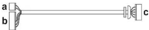
a Indoor unit side connector X35A
b Indoor unit side connector X50A (type 2)
c Adapter side connector
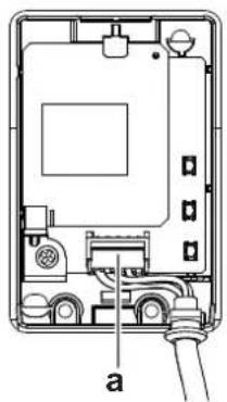
4 Fasten the cable and ensure strain relief.
natural_image
Cross-sectional diagram of an electronic device showing internal components and a labeled cable (no text or symbols present)a Connector

NOTICE
ALWAYS connect a wired or wireless remote controller (Example: BRC1H, BRC7), otherwise the online controller will NOT operate.

INFORMATION
Provide strain relief at indoor unit side by using the cable tie and cable tie mounting that are included as accessory.
5.5 Closing the adapter
5.5.1 To close the adapter
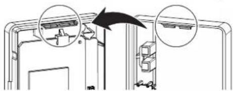
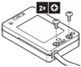
1 Hook the front casing into the rear casing.
natural_image
Diagram showing a mechanical assembly with two circular arrows pointing to components, no text or symbols present.2 Insert the two screws from the accessory bag.

NOTICE
After closing the adapter, check that the connection cable is securely fastened.
5.6 Mounting the adapter
5.6.1 About mounting the adapter
Use the adapter holder (accessory) to mount the adapter. There are 2 ways of mounting the adapter holder:
- Fixing the adapter holder to the surface using screws.
- Fixing the adapter holder to the surface using double face tape.
5.6.2 To mount the adapter

NOTICE
- If using double face tape for mounting, make sure that the part of the surface to which you mount the holder is clean and degreased.
- Make sure to mount the holder to the surface firmly, so that it can bear the weight of the adapter.

INFORMATION
The exact location of the holder depends on the type of indoor unit. For more information, visit app.daikineurope.com.
When using screws
1 Fix the adapter holder on the wall/surface with 2 screws M3×16 (accessory).
2 Slide the adapter into the holder.
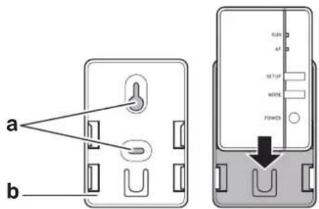
a Screw locations
b Adapter holder
When using double side tape
3 Attach the double-sided tape to the adapter holder.
4 With the tape, mount the holder to the surface.
5 Slide the adapter into the holder.
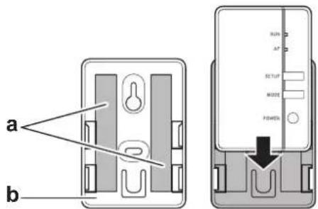
a Tape b Adapter holder
5.7 Opening the adapter
5.7.1 About opening the adapter
The average installation procedure does NOT involve opening the adapter. However, in case you do have to open it, follow below procedure.

DANGER: RISK OF ELECTROCUTION
Before opening the adapter, turn OFF the power to the indoor unit.
5.7.2 To open the adapter
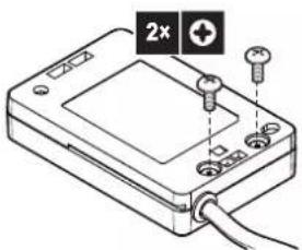
1 Remove the screws with a screwdriver.
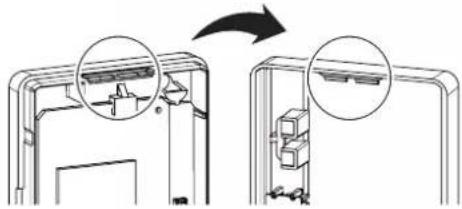
2 Unhook the front casing from the rear casing.
natural_image
Diagram showing two views of a device with internal components, one open and one closed, both without any text or symbols.6 Starting up the system
The adapter gets its power from the indoor unit. For the adapter to function, make sure it is connected to the indoor unit, and the indoor unit is powered on.
Turn on the power supply and check that the RUN lamp of the product blinks.
7 Configuration
The customer is responsible for providing:
- Smartphone or tablet with minimum supported version of Android or iOS, specified on app.daikineurope.com.
- Internet line and communication device, such as a modem, router, etc.
- Wireless LAN access point
- Installed free ONECTA application.
7.1 To install the ONECTA app
1 Open:
- Google Play for appliances using Android.
■ App Store for appliances using iOS.
2 Search for "ONECTA".
3 Follow the directions on the screen to install.
7.2 To configure the adapter
Open the ONECTA application on your smartphone or tablet PC and follow the in-app instructions.
For this Wireless LAN adapter, WPS configurator is available, follow the in-app instructions.
app.daikineurope.com

8 Hand-over to the user
After having installed and configured the adapter, hand over this installation manual to the user and make him/her aware of the following safety precautions.

DANGER
- Do NOT disassemble, modify, or repair the adapter. This can cause fire, electrical shock, or injury.
- Do NOT allow the adapter to get wet or use it when bathing or doing similar activities with water. This can cause electrical shock or fire.
- Do NOT use the adapter near medical equipment, or persons using cardiac pacemakers or defibrillators. This can cause life-threatening electromagnetic interference.
- Do NOT use the adapter near auto-control equipment such as automatic doors or fire alarm equipment. This can cause accidents due to erroneous equipment behaviour.
- In case of abnormal odour or sound, overheating, or smoke coming out of the adapter, immediately disconnect the indoor unit from its power supply. Otherwise, this can lead to fire or malfunction. If this happens, consult your dealer.
- In case you drop or damage the adapter, disconnect the indoor unit from its power supply. Otherwise, this can lead to fire or malfunction. If this happens, consult your dealer.

NOTICE
Do not use the adapter near microwave ovens. This can affect wireless LAN communications.
9 Troubleshooting
9.1 Overview: Troubleshooting
This chapter describes what to do in case of problems. It contains information about solving problems based on the symptoms listed below.
9.1.1 Symptom: The LEDs do not turn on when the adapter is connected to the unit and the unit is powered ON
| Possible causes Corrective action | |
| The adapter is wired to the wrong connectors on the indoor unit. | Make sure that the LAN adapter is correctly connected to the indoor unit.See the connection guidelines in the indoor unit manual. |
9.1.2 Symptom: The adapter is NOT responding to interaction with the indoor unit
| Possible causes Corrective action | |
| The connection cable to connect the adapter to the indoor unit is incompatible with the unit. | Make sure you are connected to a compatible unit. Check the compatibility of the indoor unit with the adapter in the indoor unit manual |
9.1.3 Symptom: Nothing happens when the adapter is in AP mode
| Possible causes Corrective action | |
| The firmware is corrupted. Contact your | dealer to report the firmware issue. |

natural_image
Blank grid paper with no text, numbers, or symbols

natural_image
Blank grid paper with no text, numbers, or symbols

natural_image
Blank grid paper with no text, numbers, or symbolsCE
UK
CA
DAIKIN INDUSTRIES CZECH REPUBLIC s.r.o.
U Nové Hospody 1/1155, 301 00 Plzeň Skvrňany, Czech Republic
DAIKIN EUROPE N.V.
- Table of contents
- About this document 3
- Specific installer safety instructions 4
- About the adapter 5
- About the box 6
- Installation 7
- Starting up the system 13
- Configuration 14
- Hand-over to the user 15
- Troubleshooting 16
- About this document
- Target audience
- Documentation set
- ■ General safety precautions:
- - Installation manual:
- - Installer reference guide:
- ■ Declaration of conformity:
- INFORMATION: Declaration of conformity
- INFORMATION
- Specific installer safety instructions
- DANGER: RISK OF ELECTROCUTION
- DANGER
- About the adapter
- Components
- Basic parameters
- Compatibility
- About the box
- To unpack the adapter
- Installation
- Precautions when installing the adapter
- Overview: Installation
- Preparing the installation site
- Installation site requirements
- Connecting the electrical wiring
- Overview of electrical connections
- About connecting the electrical wiring
- Typical workflow
- Precautions when connecting the electrical wiring
- To connect the adapter with the unit
- Connection cable for BRP069C51:
- Connection cable for BRP069C81:
- Connection cable for BRP069C82:
- NOTICE
- Closing the adapter
- To close the adapter
- Mounting the adapter
- About mounting the adapter
- To mount the adapter
- When using screws
- When using double side tape
- Opening the adapter
- About opening the adapter
- To open the adapter
- Starting up the system
- Configuration
- To install the ONECTA app
- To configure the adapter
- Hand-over to the user
- Troubleshooting
- Overview: Troubleshooting
Brand : DAIKIN
Model : BRP069C51
Category : Régulateur